
Electrical Lighting Design - An-Najah Videos
17
21-Nov-14 1 Electrical lighting design Chapter 15 in your text book LIGHTING FIXTURE (Luminaire) DISTRIBUTION
Transcript of Electrical Lighting Design - An-Najah Videos

21-Nov-14
1
Electrical lighting design
Chapter 15 in your text book
LIGHTING FIXTURE (Luminaire) DISTRIBUTION

21-Nov-14
2
• Uniformity of illumination (intensity at angles above the nadir (0º from the vertical) be greater than the intensity at 0º 15.1a.
Therefore, such fixtures can be spaced more widely than the units of Fig. 15.1b
• High efficiency ( directing the luminaries output to the work plane (i.e., from 0º to 45º from the vertical). Light above 45º is directed to the walls
• Diffuseness exists when light reaches the work plane from multiple directions. This requires that light be reflected from walls and ceilings to the work plane, which in turn requires luminaire light output above 45º from the vertical.
• Direct glare (above 45º from the vertical) glare from linear fluorescent fixtures can be minimized by placing the long axis parallel to the line of sight
LUMINAIRE LIGHT CONTROL
• Lamp Shielding
• Reflectors
(Reflector Materials)
• Diffusers
21-Nov-14
3
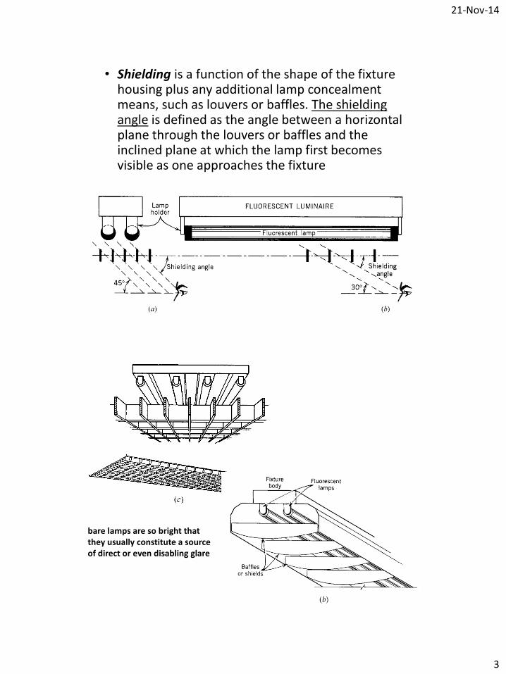
• Shielding is a function of the shape of the fixture housing plus any additional lamp concealment means, such as louvers or baffles. The shielding angle is defined as the angle between a horizontal plane through the louvers or baffles and the inclined plane at which the lamp first becomes visible as one approaches the fixture
bare lamps are so bright that they usually constitute a source of direct or even disabling glare

21-Nov-14
4
• Approximately 40% of a lamp’s output in an open luminaire is directed downward and is therefore completely independent of any reflector action.
• The difference in reflectance between a new, clean, painted surface and an old, dirty surface is, at most, 50%. That means that the maximum light loss of an open fixture due to poor maintenance is 50% of 60% (the maximum reflected light component), or 30% of the overall light output.
• The maximum reflectance of the best (and most expensive) silver reflectors is about 95%, comprising 93% specular and 2% diffuse.
• Simple cleaning of a very dirty fixture body restores 20% to 25% of the light loss. The remaining loss is due to aging of the paint.
21-Nov-14
5
Reflectors material
1. white gloss paint for portions of fixture body interiors that acted as reflectors,
2. and formed anodized aluminum sheet
The reflectance (reflection factors) of both of these materials are approximately the same, varying between 0.84 and 0.88 when new and clean
3. silver reflectors is about 95%
LUMINAIRE DIFFUSERS (page 635-638)Diffusers are the devices placed between the
lamp(s) and the illuminated space, that function to diffuse the light, control fixture brightness, redirect the light, and obscure (hide) and shield the lamps.
• Translucent Diffusers• Louvers and Baffles • Prismatic Lens• Batwing Diffusers

21-Nov-14
6
UNIFORMITY OF ILLUMINATION
• it is necessary to establish a fixture spacing that gives acceptable uniformity of illumination.
• A ratio of maximum to minimum illuminanceon the working plane of 1:1.3 is readily acceptable because lesser ratios are not easily noticed.
• For general background or circulation lighting, a ratio of up to 1.5 is acceptable

21-Nov-14
7
LUMINAIRE MOUNTING HEIGHT (S/MH)
Spacing / mounting height (from luminaries to the working plane)
Illuminance calculations – lumen method
Once a luminaire has been selected on the basis of the foregoing criteria, it remains only to calculate the number of such fixtures required in each space, for uniform general illuminance, and to arrange them properly
the lumen (lighting flux) method of average illuminancecalculation is replete with assumptions and estimates. Among these are:
1. It is assumed that the space is empty. This is not normally the case.
2. It is assumed that all surfaces are perfect diffusers. This is not the case.
3. All surfaces reflectance are estimates, 4. Maintenance conditions are estimates, at best5. And Users effects
21-Nov-14
8
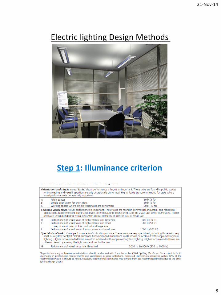
Electric lighting Design Methods
Step 1: Illuminance criterion

21-Nov-14
9
Step 2: Luminaire Selection
Example: class room 1. Low direct glare because schoolchildren spend a large
proportion of their time in a heads-up position.
2. Low veiling reflections because much of the seeing task involves high-reflectance materials, occasionally specular.
3. High efficiency and low energy use to meet ANSI/ASHRAE/IESNA Standard 90.1 and most governmental requirements.
4. Minimum required maintenance in view of the poor cleaning and maintenance situation that exists in many schools.

21-Nov-14
10
Table: 15.1 page 640
Step 3: Calculation
(N) Luminaries lumen = (n) lamps * lamb lumens
If you have two fixtures each one has three lamps each lamp has 2000 lumen
Then the overall lumen in the room is ?
E = Lumens/area

21-Nov-14
11
E = Lumens/area
E = lumens * Coefficient of utilization (CU) / Area
E = lumens * (CU) Coefficient of utilization/ Area
Room Cavity ratio

21-Nov-14
12
L : room length w : Room width

21-Nov-14
13

21-Nov-14
14
ρcc
ρw
ρf = 0.2

21-Nov-14
15
E = lumens * CU * Light Loss Factor (LLF) / Area
A. Luminaire Ambient Temperature (1) B. Voltage (1) C. Luminaire Surface Depreciation (LSD) This factor is
proportional to age and depends upon the type of surface involved
D. Components Losses due to components include ballast factor, ballast-lamp photometric factor, equipment operating factor, and lamp position (tilt) factor
E. Room Surface Dirt (RSD)
.

21-Nov-14
16
F. Lamp Lumen Depreciation (LLD)
G. BurnoutsGroup replacement procedures: 1.0
Individual replacement on burnout: 0.95
H. Luminaire Dirt Depreciation (LDD)
depends upon luminaire design, atmosphere conditions in the space, and maintenance schedule. The luminairemaintenance category is obtained from the manufacturer’s data
• Very clean = 0.95
• Clean = 0.85
• Dirty = 0.75
• Very dirty = 0.5
LLF = A*B*C*D*E*F*G*H
LLF = LSD * RSD * LLD * LDD

21-Nov-14
17
Example Calculations.
• hCC = 1.0 m
• hRC = 1.95 m
• hFC = 0.75 m
• l = 8 m
• w = 6 m
• ρC = 80%
• ρw = 50%
• ρF = 20%


![Chapter 1 General Introduction - An-Najah Videos Introduction.pdf · [1] Fall –2010 –Fluid Mechanics Dr. Mohammad N. Almasri [1] General Introduction Classification of Fluid Flows](https://static.fdocuments.net/doc/165x107/5e491e18c8dd1e3ca3068003/chapter-1-general-introduction-an-najah-videos-introductionpdf-1-fall-a2010.jpg)


