Electrical installation solutions for buildings Control ...€¦ · Electrical installation...
24
Index DBT Timer digital time switches 7/2 AG Timer electro-mechanical time switches 7/8 E 232 staircase lighting time-delay switches 7/10 CT-D range - Applications 7/12 CT-D range - Benefits and advantages 7/13 CT-D range - Operating controls 7/14 CT-D range - Selection table 7/15 E 234 electronic timers 7/16 TL Line twilight switches 7/17 TL1 Pole twilight switches 7/19 E 450 priority switches 7/20 Load management relay 7/21 E 235 mains disconnection relays 7/22 — Electrical installation solutions for buildings Control and automation 7/1 7
Transcript of Electrical installation solutions for buildings Control ...€¦ · Electrical installation...
IndexDBT Timer digital time switches 7/2AG Timer electro-mechanical time switches 7/8E 232 staircase lighting time-delay switches 7/10CT-D range - Applications 7/12CT-D range - Benefits and advantages 7/13CT-D range - Operating controls 7/14CT-D range - Selection table 7/15E 234 electronic timers 7/16TL Line twilight switches 7/17TL1 Pole twilight switches 7/19E 450 priority switches 7/20Load management relay 7/21E 235 mains disconnection relays 7/22
—Electrical installation solutions for buildingsControl and automation
7/1
7

High contrast LCD monitor for excellent visibility in all conditions due to timed back-lighting
Terminals for wires 2.5 mm2
Clear display of each contact status
Wide range of programs: standard, impulse, cycle,
random and holiday
Communication bus for the connection of DY365 2CE and DY365 4CE channel extensions along with DY GPS and DY DCF77 antennas
Permanent or temporary manual deviation, directly activated with a single touch
Sealable glass and keypad lock to prevent tampering by unauthorised personnel
7/2 E LEC TR I C A L I N S TA LL ATI O N S O LUTI O N S FO R B U I LD I N G S 2 CH C 4 2 0 0 01 C0 2 01
7
—DBT Timer digital time switchesAn ideal range for automating the functions of the installation

Wide range of programs: standard, impulse, cycle, random and holiday• Permanent or temporary manual deviation,
directly activated with a single touch• LCD Display with back-lighting • Up to 900 storable events• Up to 400 pre-defined cities coordinates• Accuracy of ±0.5 seconds/24h• Switching solar time/daylight saving time
Bluetooth communication combined with the DBT Timer APP available for Android and iOS ensure smart configuration and quick visualization. This functionality also allows to transfer programs from one device to another simply using the Smartphone.
Time synchronization via DY DCF77 or DY GPS antennas. The DY DCF77 antenna receives scheduled messages transmitted by the atomic clock installed c/o Mainflingen (Germany), near Frankfort. Thanks to this signal, the time switches are automatically setted to: hour, date and proper daylight saving time. The DY GPS antenna receives time from the Global Positioning System, providing an accurate location and time information for an unlimited number of people in all weathers, day or night, anywhere in the world; time is derived from different sources simultaneously that allow the time switch to compensate for propagation delays.
7/3
7
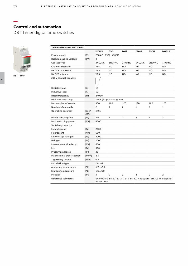
Technical features DBT Timer
DY365 DW1 DW2 DWA1 DWA2 DWTL1
Power supply [V] 230 AC (-15 % ..+10 %)
Rated pulsating voltage [kV] 4
Contact type 2NO/NC 1NO/NC 2NO/NC 1NO/NC 2NO/NC 1NO/NC
Channel extension YES NO NO NO NO NO
DY DCF77 antenna YES NO NO NO NO NO
DY GPS antenna YES NO NO NO NO NO
250 V contact capacity
Resistive load [A] 16
Inductive load [A] 10
Rated frequency [Hz] 50/60
Minimum switching 1 min (1 s pulse program)
Max number of events 900 120 120 120 120 120
Number of cahnnels 2 1 2 1 2 1
Operating accuracy [sec/ 24h]
± 0,5
Power consumption [W] 2.6 2 2 2 2 2
Max. switching power [VA] 4000
Switching capacity
Incandescent [W] 2000
Fluorescent [VA] 600
Low voltage halogen [W] 2000
Halogen [W] 2000
Low consumption lamp [VA] 600
Led [W] 500
Protection degree [IP] 20
Max terminal cross-section [mm²] 2.5
Tightening torque [Nm] 0.5
Installation type DIN rail
operating temperature [°C] -20...+50
Storage temperature [°C] -25...+70
Modules [n°] 4 2 2 2 2 2
Reference standards EN 60730-1; EN 60730-2-7; ETSI EN 301 489-1; ETSI EN 301 489-17; ETSI EN 300 328
DBT Timer
—Control and automationDBT Timer digital time switches
7/4 E LEC TR I C A L I N S TA LL ATI O N S O LUTI O N S FO R B U I LD I N G S 2 CH C 4 2 0 0 01 C0 2 01
7

Technical features Accessories for DBT Timer
DY DCF77 DY GPS
Rated voltage [V] 12 DC 12 DC
Antenna sensitivity [mV/m] 0.05
Operating temperature [°C] 0...+50 0...+50
Storage temperature [°C] -10...+60 -10...+70
Power consumption [W] 0.5
Time of the signal 5 sending/min every 30 min
Protection degree [IP] 54 54
Max. number of connected devices [No.] 31 31
Max. wiring length [m] 100 100
Terminal size for cable [mm²] 1.5 0.75..1.5
Mounting wall wall
Technical features Accessories for DBT Timer
DY365 2CE DY365 4CE
Rated voltage 12/24 V AC/DC 12/24 V AC/DC
Numbers of normaly open relays 8A/250V 2 4
Operating temperature 0 - 50°C 0 - 50°C
Storage temperature -25 - 70°C -25 - 70°C
Protection degree IP20 IP20
Mounting Din rail Din rail
Modules 2 4
Technical features Accessories for DBT Timer
DWS
Threshold 3 ÷ 500 lux
Hysteresis 1 ÷ 50 lux
Delay 1 second ÷ 30 minutes
Selection tableDigital time switches DY365 DWA1 DWA1 DW1 DW2 DWTL1
Weekly × n n n n n
Yearly n × × × × ×
Standard function n n n n n n
Astro function n n n × × n
Twilight sensor × × × × × n
Numbers of channels 2 1 2 1 2 1
DY GPS/DY DCF77 n × × × × ×
Bluetooth n n n n n n
2 or 4 channel extension n × × × × ×
Standard function includes: standard, impulse, random cycle and holiday programs.
—Control and automationDBT Timer digital time switches
7/5
7

DBT Timer digital time switchesThe unique design, with white backlight LCD display, and extreme ease of use with only four buttons, make DBT Timer ideal to automate the installation functions. The possibility to configure all digital devices via DBT Timer APP and Bluetooth connection makes the configuration and installation time even shorter. DBT Timer digital time switches are equipped with large capacity internal battery to maintain operation without power supply in order to avoid the risk of program loss and to maintain the time settings in case of power failure, respective of its duration. DBT Timer digital time switches are equipped with various functions such as the impulse, cycle, random and holiday function.
Digital yearly time switch - DY365DY365 is the digital yearly time switch with 2 channels from DBT Timer range. Thanks to the two extension channel units DY365 4CE and DY365 2CE, DY365 is able to control up to 8 channels. DY365 can be coupled with DY GPS antenna to allow synchronization received from the Global Positioning System or with DY DCF77 antenna that allows an automatic synchronization of the digital time switch with the Frankfurt DCF77 time signal.
Digital weekly time switch - DWDW1 and DW2 are weekly digital time switches with 1 and 2 channels, respectively. They allow exclusion of the normal weekly program in every week with the same mode.
Digital weekly astronomical time switch - DWAThe astronomical switches DWA1 and DWA2, respectively, with 1 and 2 channels, automatically control lighting circuits depending on the time of sunrise and sunset, greatly increasing energy efficiency. The programming is in fact based on a mathematical algorithm able to calculate the time of the rising and setting of the sun in a certain location for each day of the year. Once powered the device, simply insert date, time, geographical coordinates and time zone so that it is ready to work. These settings can also be automatically defined using the DBT Timer APP. The installation of astronomical digital time switches is particularly useful when using a twilight switch with external sensor is not recommended because it may be subject to malfunctions caused by air pollution, excessive brightness or vandalism. DWA1 and DWA2 are also indicated for the control of public lighting, shop windows of shops, neon signs, monuments, facades, illuminated fountains, …
Digital weekly twilight time switch - DWTL1DWTL1 is digital time switch with astronomical function and external luminosity probe DWS indicated for the management of the lighting system, luminous signs.Digital weekly twilight switch with 1 channel allows the exclusion of the weekly programming. DWTL1 can be configured as astronomical with probe switch which initial configuration requires the activation of the load from sunset to sunrise and during the daytime hours in case of low light. Also,it can be used as programmable twilight switch in which activation of the load occurs when the probe detects a low light condition in case that daily or weekly programming requires it.
Channels no. Bbn8012542 EAN
Order details Price1
piece
Weight1 piece kg
Packunit pc.Type code Order code
2 212010 DY365 2CSM221201R1000 0.250 1
1 225317 DW1 2CSM222531R1000 0.129 1
2 225218 DW2 2CSM222521R1000 0.152 1
1 225119 DWA1 2CSM222511R1000 0.129 1
2 225010 DWA2 2CSM222501R1000 0.152 1
1 224914 DWTL1 2CSM222491R1000 0.160 1
DY365
DW1
DWA1
DWTL1
—Control and automationDBT Timer digital time switches
7/6 E LEC TR I C A L I N S TA LL ATI O N S O LUTI O N S FO R B U I LD I N G S 2 CH C 4 2 0 0 01 C0 2 01
7
DY DCF77
DY GPS
DY365 2CE
DY365 4CE
DWS
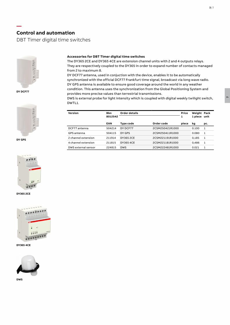
Accessories for DBT Timer digital time switchesThe DY365 2CE and DY365 4CE are extension channel units with 2 and 4 outputs relays. They are respectively coupled to the DY365 in order to expand number of contacts managed from 2 to maximum 8.DY DCF77 antenna, used in conjuction with the device, enables it to be automatically synchronized with the official DCF77 Frankfurt time signal, broadcast via long wave radio.DY GPS antenna is available to ensure good coverage around the world in any weather condition. This antenna uses the synchronization from the Global Positioning System and provides more precise values than terrestrial transmissions.DWS is external probe for light intensity which is coupled with digital weekly twilight switch, DWTL1.
Version Bbn8012542 EAN
Order details Price1 piece
Weight1 piece kg
Packunit pc.Type code Order code
DCF77 antenna 504214 DY DCF77 2CSM250421R1000 0.100 1
GPS antenna 504115 DY GPS 2CSM250411R1000 0.080 1
2 channel extension 211914 DY365 2CE 2CSM221191R1000 0,185 1
4 channel extension 211815 DY365 4CE 2CSM221181R1000 0,486 1
DWS external sensor 224815 DWS 2CSM222481R1000 0.021 1
—Control and automation DBT Timer digital time switches
7/7
7
AD1CO-15m
Technical features
AD1NO-15m
AD1NO-R-15m
AD1CO-30m
AD1CO-R-30m
AW1CO-R-210m
AD1CO-15m
AD1CO-R-15m
AW1CO-R-120m
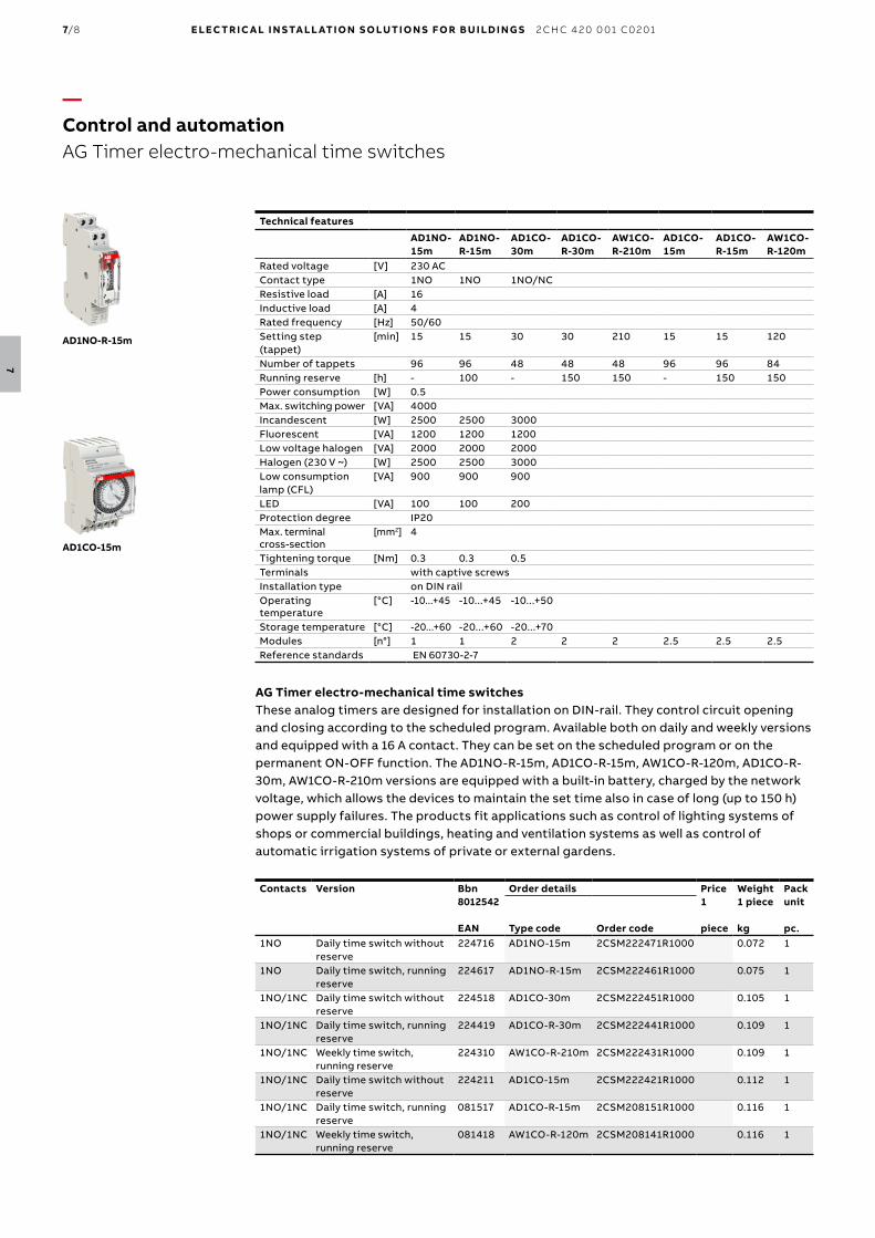
Rated voltage [V] 230 ACContact type 1NO 1NO 1NO/NCResistive load [A] 16Inductive load [A] 4Rated frequency [Hz] 50/60Setting step (tappet)
[min] 15 15 30 30 210 15 15 120
Number of tappets 96 96 48 48 48 96 96 84Running reserve [h] - 100 - 150 150 - 150 150Power consumption [W] 0.5Max. switching power [VA] 4000Incandescent [W] 2500 2500 3000Fluorescent [VA] 1200 1200 1200Low voltage halogen [VA] 2000 2000 2000Halogen (230 V ~) [W] 2500 2500 3000Low consumption lamp (CFL)
[VA] 900 900 900
LED [VA] 100 100 200Protection degree IP20Max. terminal cross-section
[mm2] 4
Tightening torque [Nm] 0.3 0.3 0.5Terminals with captive screwsInstallation type on DIN railOperating temperature
[°C] -10...+45 -10...+45 -10...+50
Storage temperature [°C] -20...+60 -20...+60 -20...+70Modules [n°] 1 1 2 2 2 2.5 2.5 2.5Reference standards EN 60730-2-7
AG Timer electro-mechanical time switchesThese analog timers are designed for installation on DIN-rail. They control circuit opening and closing according to the scheduled program. Available both on daily and weekly versions and equipped with a 16 A contact. They can be set on the scheduled program or on the permanent ON-OFF function. The AD1NO-R-15m, AD1CO-R-15m, AW1CO-R-120m, AD1CO-R-30m, AW1CO-R-210m versions are equipped with a built-in battery, charged by the network voltage, which allows the devices to maintain the set time also in case of long (up to 150 h) power supply failures. The products fit applications such as control of lighting systems of shops or commercial buildings, heating and ventilation systems as well as control of automatic irrigation systems of private or external gardens.
Contacts Version Bbn8012542 EAN
Order details Price1 piece
Weight1 piece kg
Packunit pc.Type code Order code
1NO Daily time switch without reserve
224716 AD1NO-15m 2CSM222471R1000 0.072 1
1NO Daily time switch, running reserve
224617 AD1NO-R-15m 2CSM222461R1000 0.075 1
1NO/1NC Daily time switch without reserve
224518 AD1CO-30m 2CSM222451R1000 0.105 1
1NO/1NC Daily time switch, running reserve
224419 AD1CO-R-30m 2CSM222441R1000 0.109 1
1NO/1NC Weekly time switch, running reserve
224310 AW1CO-R-210m 2CSM222431R1000 0.109 1
1NO/1NC Daily time switch without reserve
224211 AD1CO-15m 2CSM222421R1000 0.112 1
1NO/1NC Daily time switch, running reserve
081517 AD1CO-R-15m 2CSM208151R1000 0.116 1
1NO/1NC Weekly time switch, running reserve
081418 AW1CO-R-120m 2CSM208141R1000 0.116 1
AD1NO-R-15m
—Control and automationAG Timer electro-mechanical time switches
7/8 E LEC TR I C A L I N S TA LL ATI O N S O LUTI O N S FO R B U I LD I N G S 2 CH C 4 2 0 0 01 C0 2 01
7

Technical features
AD1-R-15m-72
Rated voltage [V] 230 AC
Contact type 1NO/NC
Ohmic loads [A] 16
Inductive loads [A] 4
Rated frequency [Hz] 50/60
Setting step (tappet) [Min] 15
Number of tappets 96
Running reserve [h] 100
Power loss [W] 1.8
Max. switching power [VA] 4000
Incandescent [W] 3000
Fluorescent (VA) [VA] 1200
Low voltage halogen [VA] 2000
Halogen (230 V ~) [W] 3000
Low consumption lamp (CFL) [VA] 900
LED [VA] 200
Max. terminal cross-section [mm²] 4
Tightening torque [Nm] 0.3
Installation type wall/panel
Protection degree IP20
Operating temperature [°C] -10 …+45
Storage temperature [°C] -20 …+60
Reference standards EN60730-2-7
AD1-R-15m-72 electro-mechanical time switchAD1-R-15m-72 is designed for installation on panel/wall. It is used to control circuit opening and closing according to a preset program. Available in daily version, with running reserve, it is characterized by the settings on the front, which during the holding time of the load, allows for the contact status in ON/OFF to be forced until the next switching time. The AD1-R-15m-72 is the perfect solution for controlling lighting systems in shops and public buildings, heating and irrigation systems, etc.
Contacts Version Bbn8012542 EAN
Order details Price1 piece
Weight1 piece kg
Packunit pc.Type code Order code
1NO/NC Daily time switch running reserve
081319 AD1-R-15m-72 2CSM208131R1000 0.181 1
AD1-R-15m-72
—Control and automation AG Timer electro-mechanical time switches
Selection tableAnalog time switches
AD1NO-15m
AD1NO-R-15m
AD1CO-15m
AD1CO-R-15m
AW1CO-R-120m
AD1CO-30m
AD1CO-R-30m
AW1CO-R-210m
AD1- R-15m-72
Daily n n n n × n n × n
Weekly × × × × n × × n ×
Power reserve × n* × n n × n n n*
Min. time switching
15 min 15 min 15 min 15 min 120 min 30 min 30 min 210 min 15 min
DIN rail mounting n n n n n n n n ×
Panel/wall mounting
× × × × × × × × n
Type of contacts
NO NO CO CO CO CO CO CO CO
*non-removable battery
7/9
7
—Control and automation E 232 staircase lighting time-delay switches
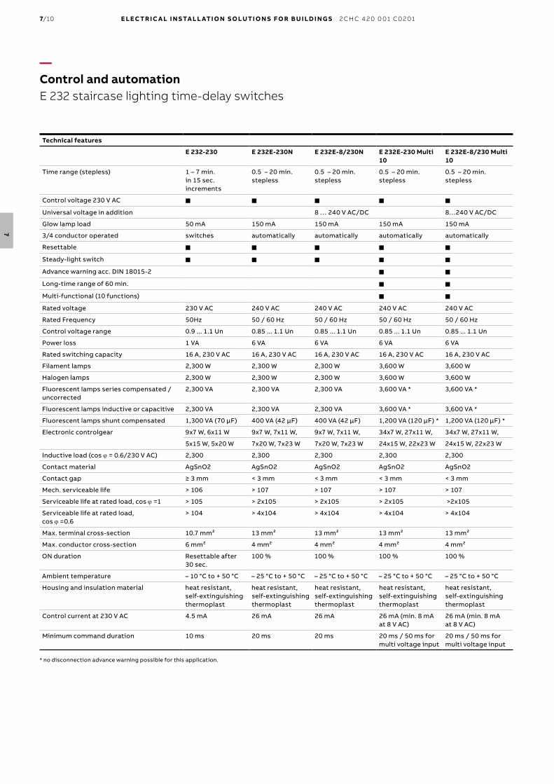
Technical features
E 232-230 E 232E-230N E 232E-8/230N E 232E-230 Multi 10
E 232E-8/230 Multi 10
Time range (stepless) 1 – 7 min. in 15 sec. increments
0.5 – 20 min. stepless
0.5 – 20 min. stepless
0.5 – 20 min. stepless
0.5 – 20 min. stepless
Control voltage 230 V AC n n n n n
Universal voltage in addition 8 … 240 V AC/DC 8…240 V AC/DC
Glow lamp load 50 mA 150 mA 150 mA 150 mA 150 mA
3/4 conductor operated switches automatically automatically automatically automatically
Resettable n n n n n
Steady-light switch n n n n n
Advance warning acc. DIN 18015-2 n n
Long-time range of 60 min. n n
Multi-functional (10 functions) n n
Rated voltage 230 V AC 240 V AC 240 V AC 240 V AC 240 V AC
Rated Frequency 50Hz 50 / 60 Hz 50 / 60 Hz 50 / 60 Hz 50 / 60 Hz
Control voltage range 0.9 ... 1.1 Un 0.85 ... 1.1 Un 0.85 ... 1.1 Un 0.85 ... 1.1 Un 0.85 ... 1.1 Un
Power loss 1 VA 6 VA 6 VA 6 VA 6 VA
Rated switching capacity 16 A, 230 V AC 16 A, 230 V AC 16 A, 230 V AC 16 A, 230 V AC 16 A, 230 V AC
Filament lamps 2,300 W 2,300 W 2,300 W 3,600 W 3,600 W
Halogen lamps 2,300 W 2,300 W 2,300 W 3,600 W 3,600 W
Fluorescent lamps series compensated / uncorrected
2,300 VA 2,300 VA 2,300 VA 3,600 VA * 3,600 VA *
Fluorescent lamps inductive or capacitive 2,300 VA 2,300 VA 2,300 VA 3,600 VA * 3,600 VA *
Fluorescent lamps shunt compensated 1,300 VA (70 μF) 400 VA (42 μF) 400 VA (42 μF) 1,200 VA (120 μF) * 1,200 VA (120 μF) *
Electronic controlgear 9x7 W, 6x11 W 9x7 W, 7x11 W, 9x7 W, 7x11 W, 34x7 W, 27x11 W, 34x7 W, 27x11 W,
5x15 W, 5x20 W 7x20 W, 7x23 W 7x20 W, 7x23 W 24x15 W, 22x23 W 24x15 W, 22x23 W
Inductive load (cos j = 0.6/230 V AC) 2,300 2,300 2,300 2,300 2,300
Contact material AgSnO2 AgSnO2 AgSnO2 AgSnO2 AgSnO2
Contact gap ≥ 3 mm < 3 mm < 3 mm < 3 mm < 3 mm
Mech. serviceable life > 106 > 107 > 107 > 107 > 107
Serviceable life at rated load, cos j =1 > 105 > 2x10⁵ > 2x10⁵ > 2x10⁵ >2x10⁵
Serviceable life at rated load, cos j =0.6
> 104 > 4x10⁴ > 4x10⁴ > 4x10⁴ > 4x10⁴
Max. terminal cross-section 10.7 mm² 13 mm² 13 mm² 13 mm² 13 mm²
Max. conductor cross-section 6 mm² 4 mm² 4 mm² 4 mm² 4 mm²
ON duration Resettable after 30 sec.
100 % 100 % 100 % 100 %
Ambient temperature – 10 °C to + 50 °C – 25 °C to + 50 °C – 25 °C to + 50 °C – 25 °C to + 50 °C – 25 °C to + 50 °C
Housing and insulation material heat resistant, self-extinguishing thermoplast
heat resistant, self-extinguishing thermoplast
heat resistant, self-extinguishing thermoplast
heat resistant, self-extinguishing thermoplast
heat resistant, self-extinguishing thermoplast
Control current at 230 V AC 4.5 mA 26 mA 26 mA 26 mA (min. 8 mA at 8 V AC)
26 mA (min. 8 mA at 8 V AC)
Minimum command duration 10 ms 20 ms 20 ms 20 ms / 50 ms for multi voltage input
20 ms / 50 ms for multi voltage input
* no disconnection advance warning possible for this application.
7/10 E LEC TR I C A L I N S TA LL ATI O N S O LUTI O N S FO R B U I LD I N G S 2 CH C 4 2 0 0 01 C0 2 01
7
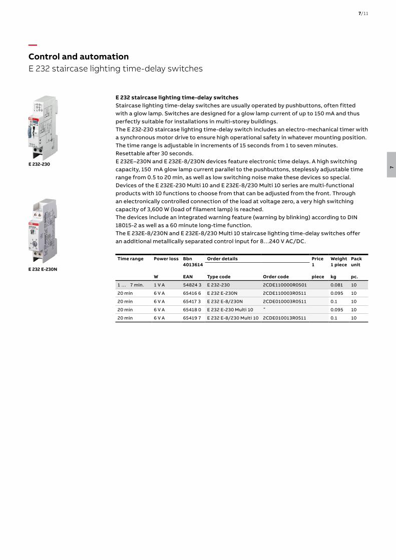
E 232 staircase lighting time-delay switchesStaircase lighting time-delay switches are usually operated by pushbuttons, often fitted with a glow lamp. Switches are designed for a glow lamp current of up to 150 mA and thus perfectly suitable for installations in multi-storey buildings.The E 232-230 staircase lighting time-delay switch includes an electro-mechanical timer with a synchronous motor drive to ensure high operational safety in whatever mounting position. The time range is adjustable in increments of 15 seconds from 1 to seven minutes. Resettable after 30 seconds.E 232E–230N and E 232E-8/230N devices feature electronic time delays. A high switching capacity, 150 mA glow lamp current parallel to the pushbuttons, steplessly adjustable time range from 0.5 to 20 min, as well as low switching noise make these devices so special.Devices of the E 232E-230 Multi 10 and E 232E-8/230 Multi 10 series are multi-functional products with 10 functions to choose from that can be adjusted from the front. Through an electronically controlled connection of the load at voltage zero, a very high switching capacity of 3,600 W (load of filament lamp) is reached.The devices include an integrated warning feature (warning by blinking) according to DIN 18015-2 as well as a 60 minute long-time function.The E 232E-8/230N and E 232E-8/230 Multi 10 staircase lighting time-delay switches offer an additional metallically separated control input for 8…240 V AC/DC.
Time range Power loss
W
Bbn4013614 EAN
Order details Price1 piece
Weight1 piece kg
Packunit pc.Type code Order code
1 … 7 min. 1 V A 54824 3 E 232-230 2CDE110000R0501 0.081 10
20 min 6 V A 65416 6 E 232 E-230N 2CDE110003R0511 0.095 10
20 min 6 V A 65417 3 E 232 E-8/230N 2CDE010003R0511 0.1 10
20 min 6 V A 65418 0 E 232 E-230 Multi 10 ˝ 0.095 10
20 min 6 V A 65419 7 E 232 E-8/230 Multi 10 2CDE010013R0511 0.1 10
E 232-230
E 232 E-230N
—Control and automation E 232 staircase lighting time-delay switches
7/11
7

A typical application for timers is delayed switching. Switching several rows of lamps on and off in corridors, stairwells, staircases, etc, is a widespread application in which the excellent functionality of the CT-D timers is undisputed.
The CT-D range is designed in a modular housing, making it well suited for building and residential applications. In just 12 order codes the CT-D range covers all the main timing functions needed for building automation, safely and reliably.
Air conditioning systems, heaters and fans can be found everywhere in buildings - just like the CT-D timers long used to switch them. On-delay, off-delay and a range of other functions cover all requirements.
Elevators, escalators, gates, compressors and doors - here too ABB timers ensure optimum and time-delayed opening as required. ABB ́s CT-D timers cover most functions with just 12 order codes.
—Control and automation CT-D rangeApplications
7/12 E LEC TR I C A L I N S TA LL ATI O N S O LUTI O N S FO R B U I LD I N G S 2 CH C 4 2 0 0 01 C0 2 01
7

The CT-D range is ideal for building applications and installation panels, due to its compact modular housing. For maximum flexibility in operation, nine single-function as well as two multifunction devices with seven timing functions are available. The devices offer four or seven time ranges from 0.05 seconds up to 100 hours. Their wide supply voltage range allows their use in applications worldwide.
Space savings
Easy to install
Global availabilty
The CT-D range is ideal for installation panels thanks to its compact modular housing. The housing’s design helps make the status and configuration more clearly visible. The CT-D range also offers a higher output current than standard industrial types. As well as the 1 c/o contacts, ABB offers devices with 2 c/o contacts for maximum flexibility.
Direct reading scales help make time setting quick and easy. A pre-selection for the time range together with an additional scale for fine adjustments help improve installation efficiency. For more flexibility, the delay time can even be changed when processes are running, making optimization to fit the application even simpler. All devices can be mounted and demounted tool-free.
The CT-D range fulfills various global standards and approvals, supporting business worldwide. Additionally, all devices from the CT-D range have a wide supply voltage from 24-48 V DC and 24-240 V AC, making it ideal for the use in installation panels around the world.
—Control and automation CT-D rangeBenefits and advantages
7/13
7
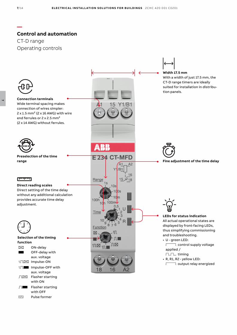
LEDs for status indicationAll actual operational states are displayed by front-facing LEDs, thus simplifying commissioning and troubleshooting.• U - green LED: V control supply voltage applied / W timing
• R, R1, R2 - yellow LED: V output relay energized
Preselection of the time range
Selection of the timing functionA ON-delayB OFF-delay with
aux. voltageCA Impulse-ON
CB Impulse-OFF with aux. voltage
DA Flasher starting with ON
DB Flasher starting with OFF
H Pulse former
Fine adjustment of the time delay
Width 17.5 mmWith a width of just 17.5 mm, the CT-D range timers are ideally suited for installation in distribu-tion panels.
Connection terminalsWide terminal spacing makes connection of wires simpler: 2 x 1.5 mm² (2 x 16 AWG) with wire end ferrules or 2 x 2.5 mm² (2 x 14 AWG) without ferrules.
Direct reading scalesDirect setting of the time delay without any additional calculation provides accurate time delay adjustment.
—Control and automation CT-D rangeOperating controls
7/14 E LEC TR I C A L I N S TA LL ATI O N S O LUTI O N S FO R B U I LD I N G S 2 CH C 4 2 0 0 01 C0 2 01
7
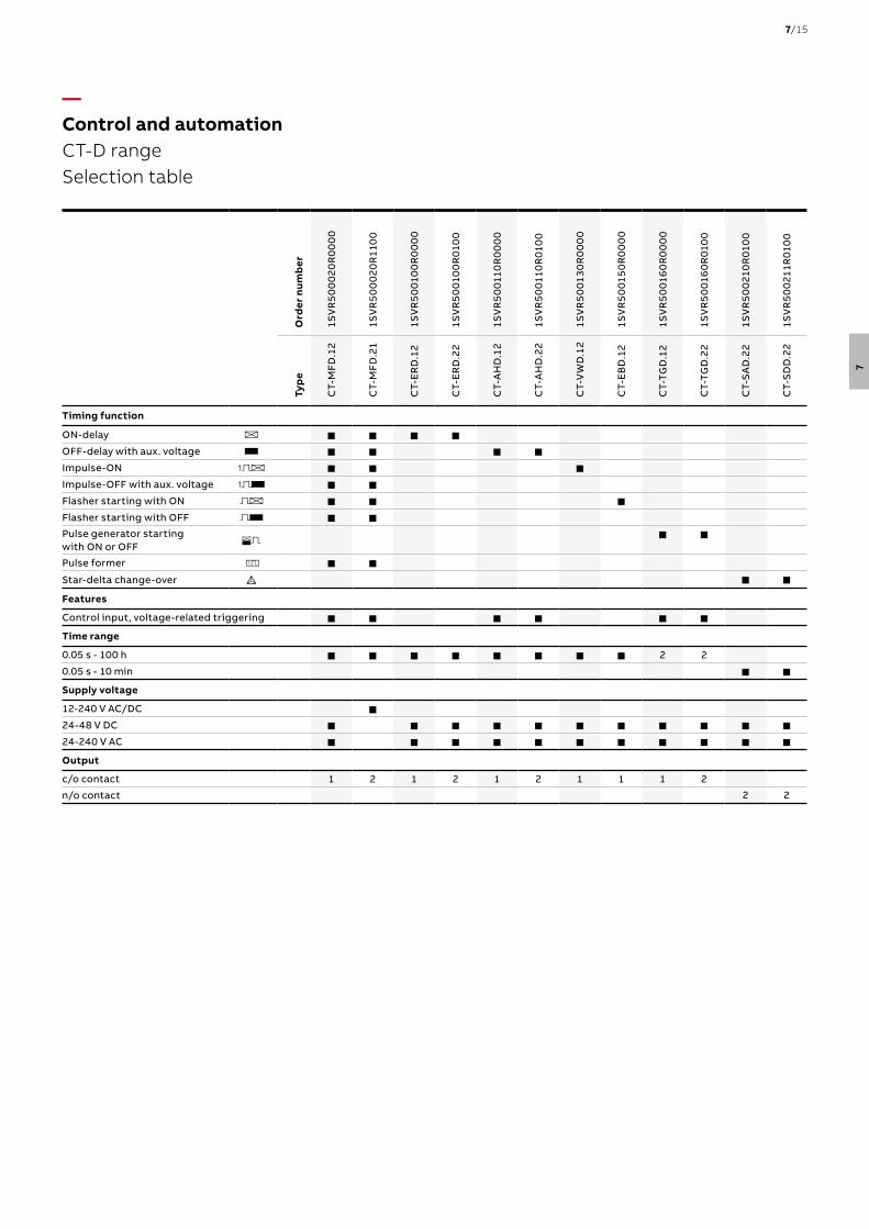
—Control and automation CT-D rangeSelection table
Ord
er n
umb
er
1SV
R5
00
02
0R
00
00
1SV
R5
00
02
0R
110
0
1SV
R5
001
00
R0
00
0
1SV
R5
001
00
R01
00
1SV
R5
001
10R
00
00
1SV
R5
001
10R
010
0
1SV
R5
001
30
R0
00
0
1SV
R5
001
50
R0
00
0
1SV
R5
001
60
R0
00
0
1SV
R5
001
60
R01
00
1SV
R5
00
210
R01
00
1SV
R5
00
211R
010
0
Typ
e
CT-
MFD
.12
CT-
MFD
.21
CT-
ER
D.1
2
CT-
ER
D.2
2
CT-
AH
D.1
2
CT-
AH
D.2
2
CT-
VW
D.1
2
CT-
EB
D.1
2
CT-
TGD
.12
CT-
TGD
.22
CT-
SA
D.2
2
CT-
SD
D.2
2
Timing function
ON-delay A J J J JOFF-delay with aux. voltage B J J J JImpulse-ON CA J J JImpulse-OFF with aux. voltage CB J JFlasher starting with ON DA J J JFlasher starting with OFF DB J JPulse generator starting with ON or OFF
EDJ J
Pulse former H J JStar-delta change-over F J JFeatures
Control input, voltage-related triggering J J J J J JTime range
0.05 s - 100 h J J J J J J J J 2 2
0.05 s - 10 min J JSupply voltage
12-240 V AC/DC J24-48 V DC J J J J J J J J J J J24-240 V AC J J J J J J J J J J JOutput
c/o contact 1 2 1 2 1 2 1 1 1 2
n/o contact 2 2
7/15
7
E 234 CT-MFD
E 234 CT-ERD
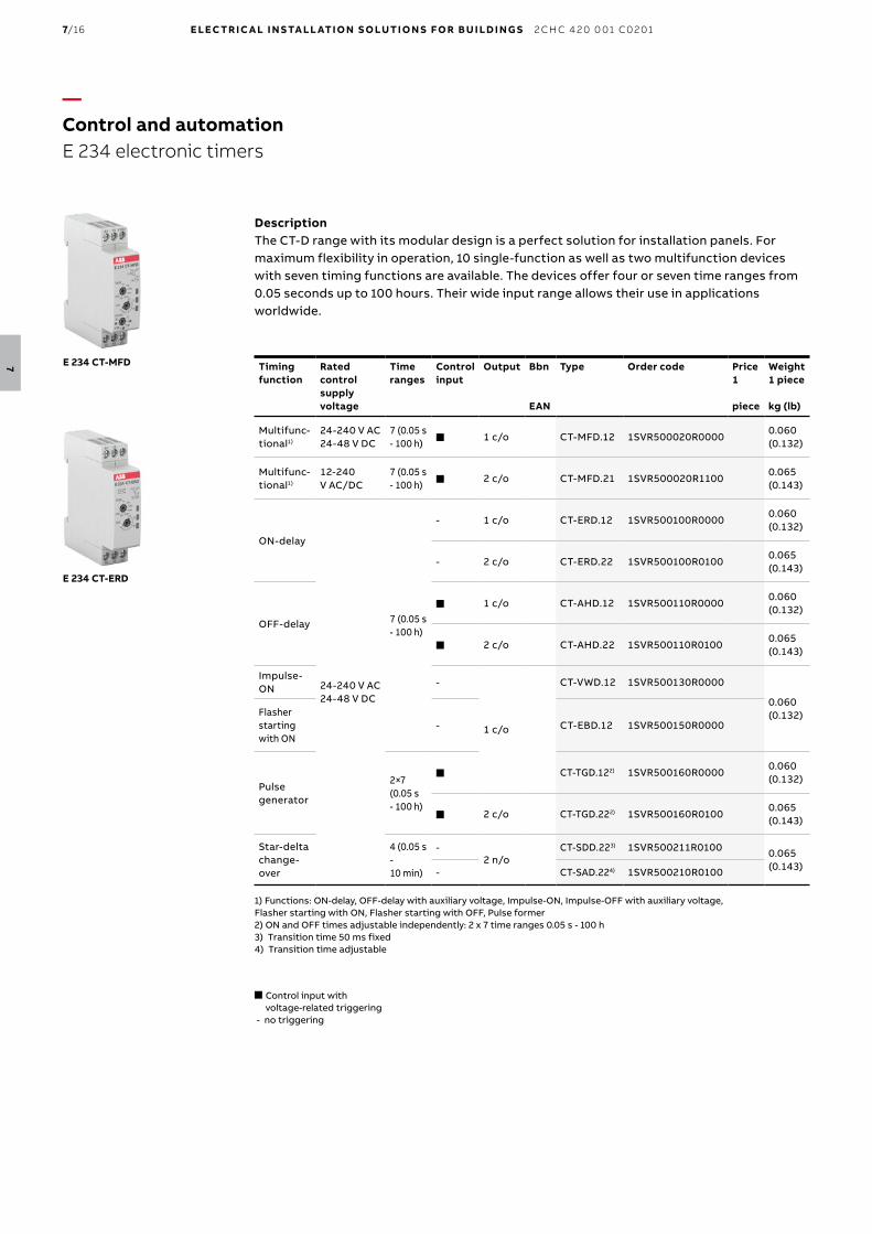
DescriptionThe CT-D range with its modular design is a perfect solution for installation panels. For maximum flexibility in operation, 10 single-function as well as two multifunction devices with seven timing functions are available. The devices offer four or seven time ranges from 0.05 seconds up to 100 hours. Their wide input range allows their use in applications worldwide.
Timing function
Rated control supply voltage
Time ranges
Control input
Output Bbn
EAN
Type Order code Price1
piece
Weight1 piece
kg (lb)
Multifunc-tional1)
24-240 V AC 24-48 V DC
7 (0.05 s - 100 h) n 1 c/o CT-MFD.12 1SVR500020R0000
0.060 (0.132)
Multifunc-tional1)
12-240 V AC/DC
7 (0.05 s - 100 h) n 2 c/o CT-MFD.21 1SVR500020R1100
0.065 (0.143)
ON-delay
24-240 V AC 24-48 V DC
7 (0.05 s - 100 h)
- 1 c/o CT-ERD.12 1SVR500100R00000.060 (0.132)
- 2 c/o CT-ERD.22 1SVR500100R01000.065 (0.143)
OFF-delay
n 1 c/o CT-AHD.12 1SVR500110R00000.060 (0.132)
n 2 c/o CT-AHD.22 1SVR500110R01000.065 (0.143)
Impulse-ON
-
1 c/o
CT-VWD.12 1SVR500130R0000
0.060 (0.132)Flasher
starting with ON
- CT-EBD.12 1SVR500150R0000
Pulse generator
2×7 (0.05 s - 100 h)
n CT-TGD.122) 1SVR500160R00000.060 (0.132)
n 2 c/o CT-TGD.222) 1SVR500160R01000.065 (0.143)
Star-delta change-over
4 (0.05 s - 10 min)
-2 n/o
CT-SDD.223) 1SVR500211R0100 0.065 (0.143)- CT-SAD.224) 1SVR500210R0100
1) Functions: ON-delay, OFF-delay with auxiliary voltage, Impulse-ON, Impulse-OFF with auxiliary voltage, Flasher starting with ON, Flasher starting with OFF, Pulse former2) ON and OFF times adjustable independently: 2 x 7 time ranges 0.05 s - 100 h3) Transition time 50 ms fixed4) Transition time adjustable
—Control and automation E 234 electronic timers
n Control input with voltage-related triggering
- no triggering
7/16 E LEC TR I C A L I N S TA LL ATI O N S O LUTI O N S FO R B U I LD I N G S 2 CH C 4 2 0 0 01 C0 2 01
7
Technical features
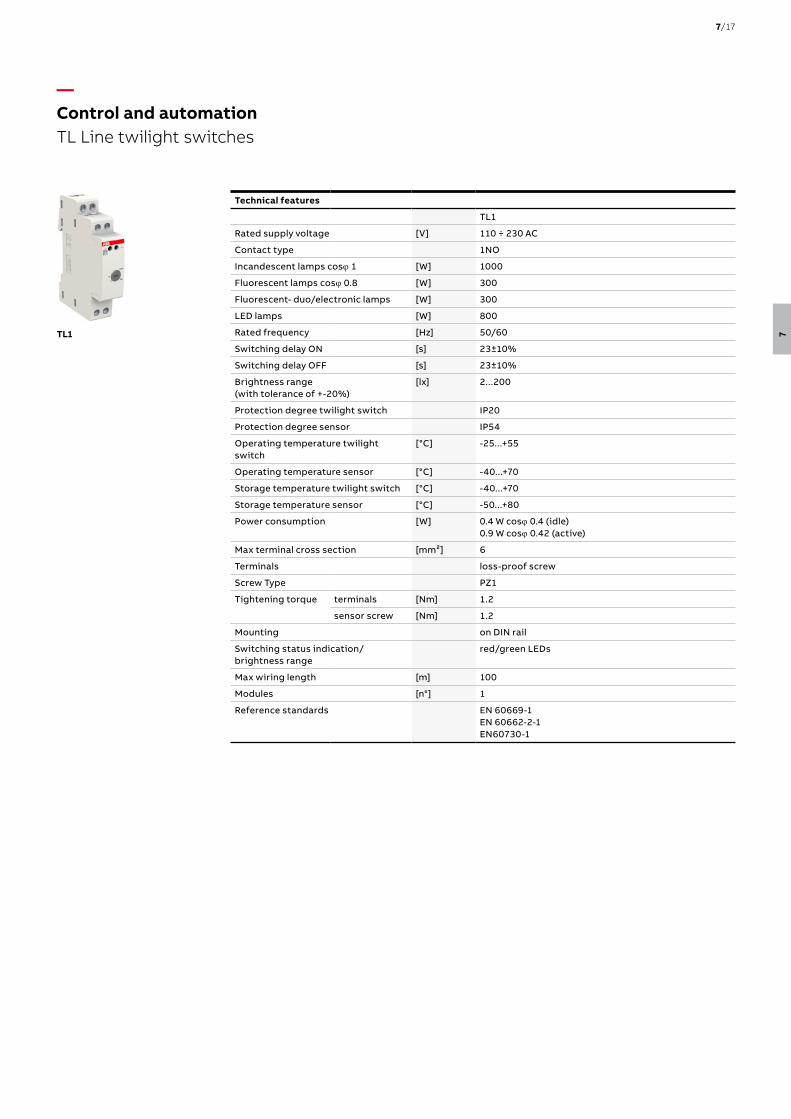
TL1
Rated supply voltage [V] 110 ÷ 230 AC
Contact type 1NO
Incandescent lamps cosj 1 [W] 1000
Fluorescent lamps cosj 0.8 [W] 300
Fluorescent- duo/electronic lamps [W] 300
LED lamps [W] 800
Rated frequency [Hz] 50/60
Switching delay ON [s] 23±10%
Switching delay OFF [s] 23±10%
Brightness range (with tolerance of +-20%)
[lx] 2...200
Protection degree twilight switch IP20
Protection degree sensor IP54
Operating temperature twilight switch
[°C] -25...+55
Operating temperature sensor [°C] -40...+70
Storage temperature twilight switch [°C] -40...+70
Storage temperature sensor [°C] -50...+80
Power consumption [W] 0.4 W cosj 0.4 (idle)0.9 W cosj 0.42 (active)
Max terminal cross section [mm²] 6
Terminals loss-proof screw
Screw Type PZ1
Tightening torque terminals [Nm] 1.2
sensor screw [Nm] 1.2
Mounting on DIN rail
Switching status indication/brightness range
red/green LEDs
Max wiring length [m] 100
Modules [n°] 1
Reference standards EN 60669-1 EN 60662-2-1 EN60730-1
TL1
—Control and automation TL Line twilight switches
7/17
7

TL Line modular twilight switchesTL1 twilight switch allows to switch ON and switch OFF lighting devices according to a scheduled level of the ambient light. It is used in combination with an external sensor to detect if the ambient light is higher or lower than the set level . A switching delay prevents them from operating unnecessarily when the light intensity suddenly changes (e.g. lightning, moving vehicles, etc.). The TL1 twilight switch 1 channel is preset with a 10 LUX from factory and it is equipped with 2 signalling LEDs that indicate the setpoint value and display the status of the contact . The operating instructions are printed on the side of the product.
Brightness range
lx
Bbn8012542 EAN
Order details Price1 piece
Weight1 piece kg
Packunit pc.Type code Order code
2:200 299219 TL1 2CSM229921R1341 0,155 1
Accessories for TL Line modular twilight switchesThe external sensor TLs is supplied in the same package of the switch,TL1, but it’s also available separately as spare part. The upper part of the external case (with screw locking), made up of thermoplastic material, bears up against ultraviolet rays to guarantee an homogeneous diffusion of the daylight internally. The sensor is also equipped with a cable gland.
Bbn8012542 EAN
Order details Price1 piece
Weight1 piece kg
Packunit pc.Type code Order code
External sensor 299318 TLs 2CSM229931R1341 0,008 1
TL1
TLs
—Control and automation TL Line twilight switches
7/18 E LEC TR I C A L I N S TA LL ATI O N S O LUTI O N S FO R B U I LD I N G S 2 CH C 4 2 0 0 01 C0 2 01
7
Technical features
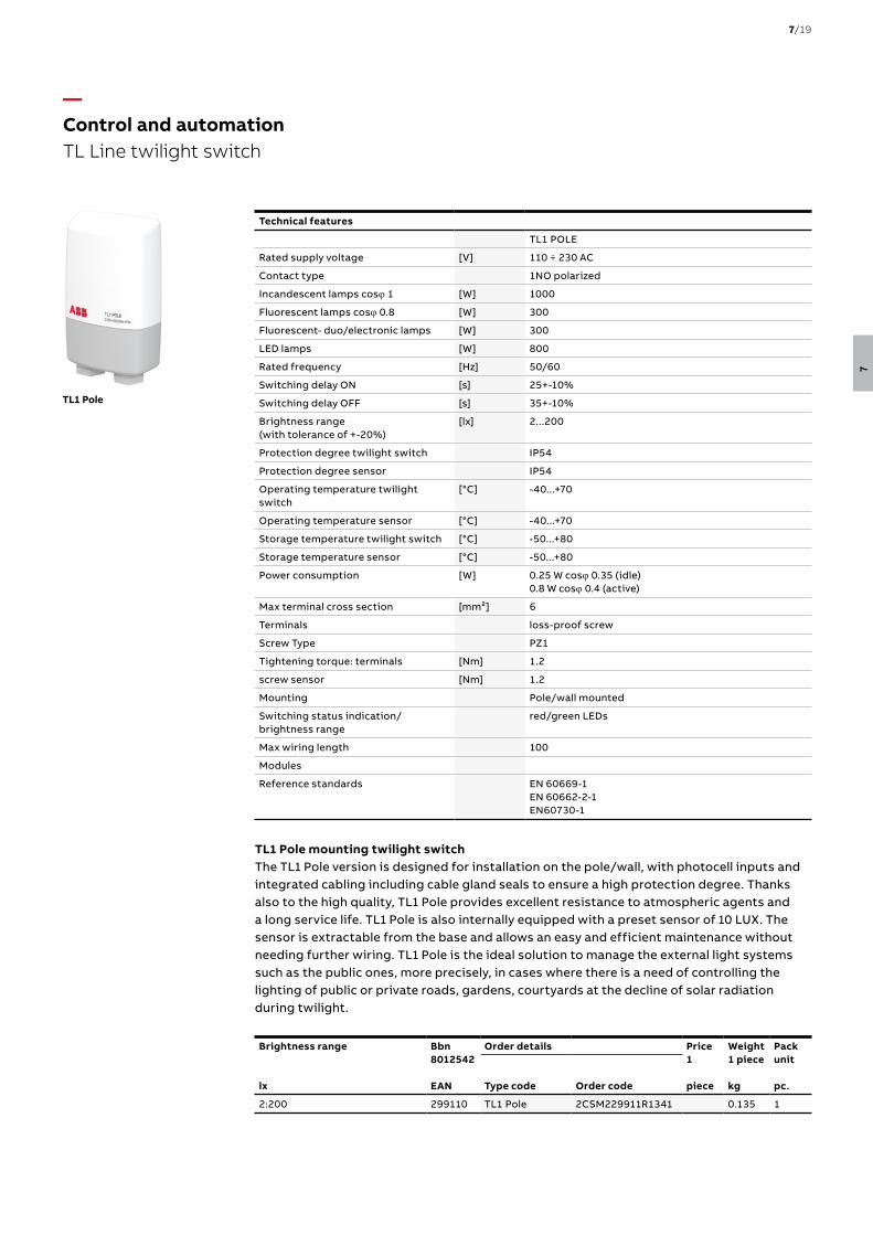
TL1 POLE
Rated supply voltage [V] 110 ÷ 230 AC
Contact type 1NO polarized
Incandescent lamps cosj 1 [W] 1000
Fluorescent lamps cosj 0.8 [W] 300
Fluorescent- duo/electronic lamps [W] 300
LED lamps [W] 800
Rated frequency [Hz] 50/60
Switching delay ON [s] 25+-10%
Switching delay OFF [s] 35+-10%
Brightness range (with tolerance of +-20%)
[lx] 2...200
Protection degree twilight switch IP54
Protection degree sensor IP54
Operating temperature twilight switch
[°C] -40...+70
Operating temperature sensor [°C] -40...+70
Storage temperature twilight switch [°C] -50...+80
Storage temperature sensor [°C] -50...+80
Power consumption [W] 0.25 W cosj 0.35 (idle)0.8 W cosj 0.4 (active)
Max terminal cross section [mm²] 6
Terminals loss-proof screw
Screw Type PZ1
Tightening torque: terminals [Nm] 1.2
screw sensor [Nm] 1.2
Mounting Pole/wall mounted
Switching status indication/brightness range
red/green LEDs
Max wiring length 100
Modules
Reference standards EN 60669-1 EN 60662-2-1 EN60730-1
TL1 Pole mounting twilight switchThe TL1 Pole version is designed for installation on the pole/wall, with photocell inputs and integrated cabling including cable gland seals to ensure a high protection degree. Thanks also to the high quality, TL1 Pole provides excellent resistance to atmospheric agents and a long service life. TL1 Pole is also internally equipped with a preset sensor of 10 LUX. The sensor is extractable from the base and allows an easy and efficient maintenance without needing further wiring. TL1 Pole is the ideal solution to manage the external light systems such as the public ones, more precisely, in cases where there is a need of controlling the lighting of public or private roads, gardens, courtyards at the decline of solar radiation during twilight.
Brightness range
lx
Bbn8012542 EAN
Order details Price1 piece
Weight1 piece kg
Packunit pc.Type code Order code
2:200 299110 TL1 Pole 2CSM229911R1341 0.135 1
TL1 Pole
—Control and automation TL Line twilight switch
7/19
7

Technical characteristics
E 451-5.7 E 452-5.7
Operating coil
Range of rated current equivalent to 6.7 … 39 Acorrelates1.5 … 9 kW at 230 V, 4.6 … 27 kW at 230/400 V
Threshold current 3.1 … 5.3 A
OFF delay (max.) 0 main half waves 2 main half waves
Max. continuous current 43 A
Therm. continuous capacity at 40 °C/104 °F 5 W
Contact assembly
Control contact 1 NC contact
Rated contact current at 250 V 1 A
Contact material solid silver
Max. switching voltage 400 V
Max. switching capacity 230 VA
Max. switched current 1 A
Max. inrush current peak 5 A
Electr. service life > 105 operations
Mechanical service life app. 2 x 10⁶ operations
Max. electrical switching rate app. 1800 operations/hour
ON duration 100 %
Ambient temperature – 20 °C/– 4 °F to + 40 °C/104 °F
Response time 10 … 20 ms
Release time 5 … 20 ms ≥ 20 ms
Test voltage contact/coil 2.5 kV
Clearance and creepage distance C/250 V AC cording to IEC 669-1-23
Protection degree IP 40
Protection against electric shock according to DIN VDE 0106 Part 100 (BGV A2)
Terminal contact series coil up to 16 mm2, control contact up to 2.5 mm2
E 450 priority switchesThe priority switch is used in wiring systems where existing lead cross sections or the size of the power supply service box do not allow for simultaneous operation of two powerful loads (e.g. storage heating and flow-type heater).The priority switch disconnects the long-term load (storage heating) for as long as the short-term consumer (flow-type heater) is switched on.The coil of the priority switch is connected in series to the short-term load. When this load is switched on, the NC contact of the priority switch disconnects e.g. the heating system contactor.
For pneumatically controlled flow-type heaters
Rated current range
Power loss
W
Bbn4016779 EAN
Order details Price1
piece
Weight1 piece kg
Packunit pc.Type code Order code
6,7 ... 39 A 2.4 41590 3 E 451- 5.7 A 2CDE160000R0901 0.1 10
For electronically controlled flow-type heaters
Rated current range
Power loss
W
Bbn4016779 EAN
Order details Price1
piece
Weight1 piece kg
Packunit pc.Type code Order code
6.7 ... 39 A 2.4 20950 2 E 452-5.7 A 2CDE160010R0901 0.1 10
E 450
—Control and automation E 450 priority switches
7/20 E LEC TR I C A L I N S TA LL ATI O N S O LUTI O N S FO R B U I LD I N G S 2 CH C 4 2 0 0 01 C0 2 01
7
Technical characteristics
LCR
Input
Rated voltage Un [Vac] 230 (-15%/+10%)
Rated frequency [Hz] 50/60
Rated capacity In [A] 32
Power consumption [VA] 4
Display
Type of display backlit LCD
Resolution [kW] 0.01
Display dimensions [mm] 27 × 23
Non-priority load
Regulating thresholds [kW] 0.8..7
Resolution of threshold [kW] 0.1
Delay of loads disconnection [sec] 0..9999
Delay between one connection and the next one [sec] 0..9999
Alarm notification LED // buzzer
Relay output
Rated current [A] 16
Rated voltage [Vac] 250
Climatic conditions
Storage temperature -10°C to +65°C
Operating temperature -10°C to +45°C
Relative humidity max. 90% (non-condensing)
Protection degree
At terminals IP20
On the front panel IP51
Max cable cross-section
rigid [mm2] 4
flexible [mm2] 6
Modules (18mm) [No.] 2
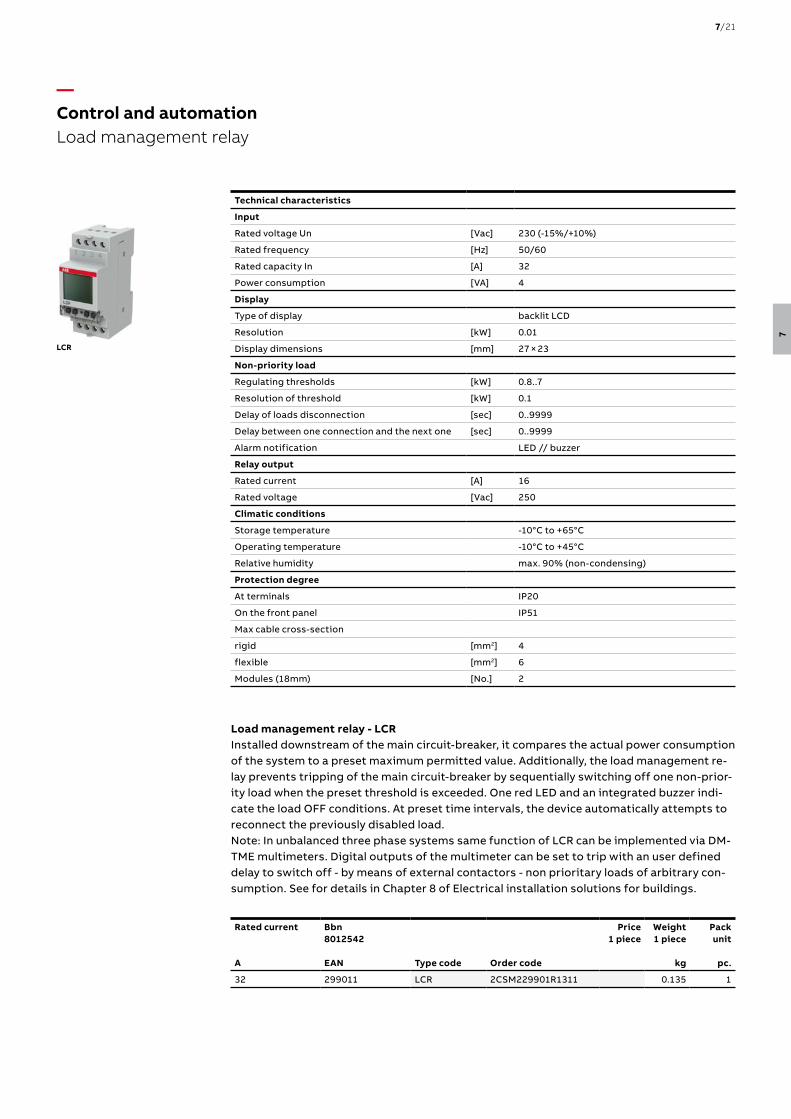
Load management relay - LCRInstalled downstream of the main circuit-breaker, it compares the actual power consumption of the system to a preset maximum permitted value. Additionally, the load management re-lay prevents tripping of the main circuit-breaker by sequentially switching off one non-prior-ity load when the preset threshold is exceeded. One red LED and an integrated buzzer indi-cate the load OFF conditions. At preset time intervals, the device automatically attempts to reconnect the previously disabled load. Note: In unbalanced three phase systems same function of LCR can be implemented via DM-TME multimeters. Digital outputs of the multimeter can be set to trip with an user defined delay to switch off - by means of external contactors - non prioritary loads of arbitrary con-sumption. See for details in Chapter 8 of Electrical installation solutions for buildings.
Rated current
A
Bbn8012542 EAN
Price1 piece
Weight1 piece
kg
Packunit
pc.Type code Order code
32 299011 LCR 2CSM229901R1311 0.135 1
—Control and automationLoad management relay
7/21
7

E 235
—Control and automation E 235 mains disconnection relays
Technical features
Short circuit rupturing capacity 16 A/230 AC
Rated frequency 50/60 Hz
Range of control voltage 0.9 to 1.1 Un
Filament lamps 2300 W
Fluorescent lamps:
twin lamp circuit 100 W
shunt compensated 56 W
electronic ballast max. 36 W, dependent on manufacturer
Inductive load cosj 0.6 6 A
Max. switching capacity (cosj 0.5) 3500 VA
Intrinsic consumption ca. 1 W
Control voltage 5 V a.c.
Adjustable making capacity 2 - 15 VA
Breaking capacity 0.66 x making capacity
ON delay 50 ms
OFF delay ca. 3 sec.
Contact assembly 1 NO contact
Service life at rated load > 100000 switching cycles
Ambient temperature - 10 °C/14 °F to +45 °C/113 °F
Max terminal cross-section 2.5 mm2
7/22 E LEC TR I C A L I N S TA LL ATI O N S O LUTI O N S FO R B U I LD I N G S 2 CH C 4 2 0 0 01 C0 2 01
7
E 235-NFS
E 235-GLE
E 235 Mains disconnection relay
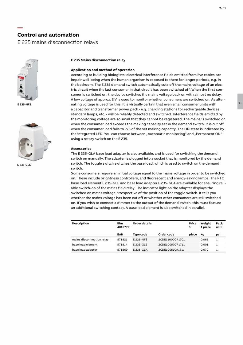
Application and method of operationAccording to building biologists, electrical interference fields emitted from live cables can impair well-being when the human organism is exposed to them for longer periods, e.g. in the bedroom. The E 235 demand switch automatically cuts off the mains voltage of an elec-tric circuit when the last consumer in that circuit has been switched off. When the first con-sumer is switched on, the device switches the mains voltage back on with almost no delay. A low voltage of approx. 3 V is used to monitor whether consumers are switched on. As alter-nating voltage is used for this, it is virtually certain that even small consumer units with a capacitor and transformer power pack - e.g. charging stations for rechargeable devices, standard lamps, etc. - will be reliably detected and switched. Interference fields emitted by the monitoring voltage are so small that they cannot be registered. The mains is switched on when the consumer load exceeds the making capacity set in the demand switch. It is cut off when the consumer load falls to 2/3 of the set making capacity. The ON state is indicated by the integrated LED. You can choose between „Automatic monitoring“ and „Permanent ON“ using a rotary switch on the E 235.
AccessoriesThe E 235-GLA base load adapter is also available, and is used for switching the demand switch on manually. The adapter is plugged into a socket that is monitored by the demand switch. The toggle switch switches the base load, which is used to switch on the demand switch.Some consumers require an initial voltage equal to the mains voltage in order to be switched on. These include brightness controllers, and fluorescent and energy-saving lamps. The PTC base load element E 235-GLE and base load adapter E 235-GLA are available for ensuring reli-able switch-on of the mains field relay. The indicator light on the adapter displays the switched on mains voltage, irrespective of the position of the toggle switch. It tells you whether the mains voltage has been cut off or whether other consumers are still switched on. If you wish to connect a dimmer to the output of the demand switch, this must feature an additional switching contact. A base load element is also switched in parallel.
Description Bbn4016779 EAN
Order details Price1
piece
Weight1 piece kg
Packunit pc.Type code Order code
mains disconnection relay 571821 E 235-NFS 2CDE110000R1701 0.065 1
base load element 571814 E 235-GLE 2CDE100500R1711 0.001 1
base load adapter 571869 E 235-GLA 2CDE100510R1711 0.070 1
—Control and automation E 235 mains disconnection relays
7/23
7

7/24 E LEC TR I C A L I N S TA LL ATI O N S O LUTI O N S FO R B U I LD I N G S 2 CH C 4 2 0 0 01 C0 2 01
7


![IS 4648 (1968): Guide for Electrical Layout in Residential Buildings · IS 4648 (1968): Guide for Electrical Layout in Residential Buildings [ETD 20: Electrical Installation] Title:](https://static.fdocuments.net/doc/165x107/60049f3078445e280b63ccd5/is-4648-1968-guide-for-electrical-layout-in-residential-buildings-is-4648-1968.jpg)