Electrical Equipment Code 2-nd Edition - · PDF fileELECTRICAL EQUIPMENT CODE PO-KO-010 ver....
117
ELECTRICAL EQUIPMENT CODE PO-KO-010 ver. 2.2 page 1 from 114 ELECTRICAL EQUIPMENT CODE December 2013
Transcript of Electrical Equipment Code 2-nd Edition - · PDF fileELECTRICAL EQUIPMENT CODE PO-KO-010 ver....

ELECTRICAL EQUIPMENT CODE
PO-KO-010
ver. 2.2 page 1 from 114
ELECTRICAL EQUIPMENT CODE
December 2013

ELECTRICAL EQUIPMENT CODE
PO-KO-010
ver. 2.2 page 2 from 114
TABLE OF CONTENTS
1 Introduction ....................................................................................................... 9
2 Glossary and Definitions ................................................................................. 10
3 Service Conditions ........................................................................................... 13
3.1 General.............................................................................................................................................. 13
3.2 Nominal Current Ratings of Equipment ..................................................................................... 13
3.3 Normal Service Conditions ........................................................................................................... 14
3.3.2 Indoor Plant .......................................................................................................................................... 15
3.3.3 Outdoor Plant ....................................................................................................................................... 15
3.3.4 Protection and Control Equipment Operating Environments .................................................... 15
3.3.5 Fault Clearance ..................................................................................................................................... 16
3.3.6 Multi-pole Opening/Tripping and Auto-reclosing ........................................................................ 17
3.3.7 Special Service Conditions .................................................................................................................. 17
4 Substations ...................................................................................................... 20
4.1 Technical Requirements for Substations Connected to the Transmission System .............. 20
4.2 General Requirements .................................................................................................................... 20
4.2.1 Designing For Safety ........................................................................................................................... 20
4.3 Legal Requirements ........................................................................................................................ 20
4.4 Environmental Impact ................................................................................................................... 20
4.5 Design Life of Installations ........................................................................................................... 21
4.6 Operational Access ......................................................................................................................... 21
4.7 Maintenance Requirements ........................................................................................................... 21
4.8 Interlocking (Conditions of operation) ....................................................................................... 22
4.9 Current Transformers..................................................................................................................... 22
4.10 Switchgear Secondary Isolation .................................................................................................... 22
4.11 Voltage Transformer Secondary Isolation .................................................................................. 22
4.12 Earthing ............................................................................................................................................ 22
4.13 Equipment Identification ............................................................................................................... 22
4.14 Secondary Equipment .................................................................................................................... 23
4.15 Substation Auxiliary Cabling ......................................................................................................... 24
4.16 Segregation of Equipment owned by TSO and System Users ................................................ 24
4.17 Lifting Equipment ........................................................................................................................... 25

ELECTRICAL EQUIPMENT CODE
PO-KO-010
ver. 2.2 page 3 from 114
4.18 Substation Facilities ........................................................................................................................ 25
4.19 Site Security ...................................................................................................................................... 26
4.20 Fire Protection ................................................................................................................................. 26
4.21 Disturbance Recorder..................................................................................................................... 26
4.22 General Requirements Applicable to AIS Substations ............................................................. 27
4.22.1 Electrical Clearances ............................................................................................................................ 27
4.22.2 Safety Clearances/Distances .............................................................................................................. 27
4.22.3 Clearances to Perimeter Fences ......................................................................................................... 29
4.22.4 Clearance to Roadways ....................................................................................................................... 29
4.22.5 Substation Profile ................................................................................................................................. 29
4.22.6 Earthing Devices .................................................................................................................................. 30
4.22.7 Portable Earthing ................................................................................................................................. 30
4.23 General Requirements applicable to GIS Substations .............................................................. 31
4.23.1 Buildings ................................................................................................................................................ 31
4.23.2 AIS Connections .................................................................................................................................. 31
4.23.3 Portable Maintenance Earthing Devices (PMEDs) ....................................................................... 31
4.23.4 Gas service connections ...................................................................................................................... 31
4.23.5 Pressure/Density Indication .............................................................................................................. 31
4.23.6 SF6 Gas Alarm Scheme ...................................................................................................................... 32
4.23.7 Location of Light Current Equipment ............................................................................................. 32
4.24 Performance Requirements for all Switchgear ........................................................................... 32
4.24.1 Jointing of Current Carrying Conductors ........................................................................................ 32
4.24.2 Primary Equipment ............................................................................................................................. 32
4.25 Routine Tests at Site ....................................................................................................................... 32
4.25.1 Current Carrying Conductors ............................................................................................................ 32
4.26 Conductor Jointing in Substations ............................................................................................... 33
4.26.1 Introduction to Conductor Jointing.................................................................................................. 33
4.26.2 Jointing Guidelines .............................................................................................................................. 33
4.26.3 Preparation of Surfaces of Bolted Joints .......................................................................................... 34
4.26.4 Preparation of Tinned or Plated Surfaces of Bolted Joints ........................................................... 34
4.26.5 Assembly of Bolted Joints .................................................................................................................. 35
4.26.6 Service Performance of Bolted Joints ............................................................................................... 35
4.26.7 Gas Shielded Electric Arc Welded Joints (MIG – TIG) ............................................................... 35
4.26.8 Fusion Electric Arc Welding, Gas Brazing and High Temperature Soldering .......................... 36

ELECTRICAL EQUIPMENT CODE
PO-KO-010
ver. 2.2 page 4 from 114
4.26.9 Explosive Jointing / Cold Pressure Welding................................................................................... 36
4.26.10 Compression Jointing .............................................................................................................. 36
5 Switchgear ....................................................................................................... 37
5.1 General Technical Requirements.................................................................................................. 37
5.1.2 Compressed Gas .................................................................................................................................. 37
5.1.3 Operating Mechanisms and Enclosures ........................................................................................... 38
5.1.4 Outage Constraints .............................................................................................................................. 38
5.2 Technical Requirements for Gas Insulated Switchgear ............................................................ 39
5.2.2 SF6 Gas Service Connections ............................................................................................................ 39
5.2.3 Partial Discharge Measurement ......................................................................................................... 41
5.2.4 Performance Requirements ................................................................................................................ 41
5.2.5 Sulphur Hexafluoride Gas (SF6) ........................................................................................................ 43
6 Circuit Breakers ............................................................................................... 43
6.2 General Requirements .................................................................................................................... 43
6.2.1 General Requirements for Circuit breakers ..................................................................................... 43
6.2.2 General Requirements for Mechanisms and Stored Energy Systems ......................................... 44
6.2.3 General Requirements for Control Schemes and Circuitry .......................................................... 46
6.2.4 Additional General Requirements for Special Purpose Circuit breakers for Capacitor Bank Switching ................................................................................................................................... 48
6.2.5 Additional General Requirements for Special Purpose Circuit breakers for Shunt Reactor Switching ................................................................................................................................... 48
6.3 Performance Requirements ........................................................................................................... 48
6.3.2 Performance Requirements for Special Purpose Circuit breakers for Capacitor Bank Switching ................................................................................................................................... 49
7 Disconnectors and Earthing Switches ............................................................ 50
7.1.2 Rated Short-Time Withstand Current .............................................................................................. 50
7.1.3 Divided Frame Disconnectors and Earthing Switches .................................................................. 50
7.1.4 Bus-transfer Duty ................................................................................................................................. 50
7.1.5 Rated Values of Mechanical Endurance for Disconnectors ......................................................... 50
7.1.6 Rated Values of Electrical Endurance for Earth Switches ............................................................ 50
7.2 General Requirements for Disconnectors and Earth Switches ............................................... 51
7.2.1 Clearance Distances ............................................................................................................................. 51
7.2.2 Simultaneous Operation of Poles ...................................................................................................... 51

ELECTRICAL EQUIPMENT CODE
PO-KO-010
ver. 2.2 page 5 from 114
7.2.3 Flexibility of Design and Setting Adjustment Tolerances ............................................................. 51
7.2.4 Position Indication ............................................................................................................................... 51
7.2.5 Mechanical Key Interlocking ............................................................................................................. 52
7.2.6 GIS Combined Disconnectors and Earthing Switches ................................................................. 52
7.2.7 Drive System Mechanical Interference Device ............................................................................... 52
7.2.8 'Lockout' Interlock Keys ..................................................................................................................... 52
7.2.9 Earthing Switch Magnetic Bolt Device ............................................................................................ 53
7.2.10 Operations Counter ............................................................................................................................. 53
7.2.11 Construction Materials and Protective Coatings ............................................................................ 53
7.3 Operating Mechanisms, Ancillary Equipment and their Enclosures ...................................... 53
7.3.1 'Sealing In' of Control Circuits ........................................................................................................... 53
7.3.2 Drive Limit Switch ............................................................................................................................... 53
7.3.3 Control Switches .................................................................................................................................. 53
7.3.4 Auxiliary Switches ................................................................................................................................ 54
8 Substation Interlocking Schemes .................................................................... 54
8.1 General Requirements .................................................................................................................... 54
8.1.2 Mechanical Interlocking ...................................................................................................................... 56
8.2 Performance Requirements ........................................................................................................... 56
9 Solid Core Post Insulators for Substations ...................................................... 56
9.2 Type Tests ........................................................................................................................................ 56
9.2.2 Routine Testing .................................................................................................................................... 57
10 Bushings .......................................................................................................... 57
10.1 General Requirements .................................................................................................................... 57
10.2 Performance Requirements ........................................................................................................... 58
10.3 Type Test Requirements ................................................................................................................ 58
10.4 Routine Test Requirements ........................................................................................................... 58
11 Surge Arresters ................................................................................................ 59
11.1 General requirements for all Surge Arresters ............................................................................. 59
11.1.2 Air Insulated Surge Arresters ............................................................................................................. 59
11.1.3 Gas Insulated Surge Arresters ............................................................................................................ 60
11.2 Functional and Performance Requirements ............................................................................... 60
11.3 Type Tests ........................................................................................................................................ 61

ELECTRICAL EQUIPMENT CODE
PO-KO-010
ver. 2.2 page 6 from 114
11.4 Routine Tests ................................................................................................................................... 62
11.5 Commissioning Tests ..................................................................................................................... 62
11.6 Condition Monitoring and Maintenance ..................................................................................... 62
12 Measurement Transformers ............................................................................ 63
12.2 Current Transformers..................................................................................................................... 64
12.2.2 Type Tests ............................................................................................................................................. 69
12.2.3 Routine Tests ........................................................................................................................................ 70
12.2.4 Routine Test Reports .......................................................................................................................... 70
12.3 Voltage Transformers ..................................................................................................................... 72
12.3.2 Performance Requirements of VTs .................................................................................................. 72
12.3.3 Type Tests ............................................................................................................................................. 74
12.3.4 Routine Tests ........................................................................................................................................ 75
12.3.5 Routine Test Reports .......................................................................................................................... 75
13 Earthing ........................................................................................................... 77
13.1.2 Rise of Earth Potential ........................................................................................................................ 77
13.1.3 Earth Electrodes .................................................................................................................................. 79
13.1.4 Earth Electrode Arrangement ........................................................................................................... 80
13.1.5 Test Facilities ........................................................................................................................................ 81
13.1.6 Equipment Connected to the Main earth system ........................................................................... 81
13.1.7 Installation ............................................................................................................................................. 82
13.1.8 Portable Earthing ................................................................................................................................. 83
13.1.9 Steel Support Structures ...................................................................................................................... 84
13.1.10 Fences ........................................................................................................................................ 84
13.1.11 Access/Egress Gates ............................................................................................................... 85
13.1.12 Temporary Fences.................................................................................................................... 86
13.1.13 Terminal Towers ...................................................................................................................... 86
13.1.14 Gas Insulated Substations ....................................................................................................... 86
13.1.15 Anti-climbing Precautions along the Tops of Walls ........................................................... 87
13.1.16 Design Life of Installation ...................................................................................................... 87
13.2 Test Requirements .......................................................................................................................... 87
14 Auxiliary Supplies ............................................................................................ 87
14.2 Performance Requirements ........................................................................................................... 89
ELECTRICAL EQUIPMENT CODE
PO-KO-010
ver. 2.2 page 7 from 114
14.2.1 Alternating Current Supplies .............................................................................................................. 89
14.2.2 Direct Current Supplies ...................................................................................................................... 89
15 Protection and Protection Grading ................................................................. 90
15.2 Protection Principles ...................................................................................................................... 91
15.2.1 Use of Differential Protection on Short Feeders ............................................................................ 91
15.2.2 Supervision of Circuit Breaker Main Contacts and Trip Circuits ................................................ 91
15.2.3 Fault location facilities on long overhead line circuits ................................................................... 91
15.2.4 Power System Instability and Under Frequency ............................................................................. 92
15.2.5 400 kV Network ................................................................................................................................... 92
15.2.6 220 kV Network ................................................................................................................................... 93
15.2.7 110 kV Network ................................................................................................................................... 93
15.2.8 Breaker Fail Protection ....................................................................................................................... 94
15.3 Use of shared Current Transformers ........................................................................................... 94
15.4 Transformer Protection ................................................................................................................. 94
15.5 Overcurrent Protection on Networks of System Users ............................................................ 95
16 Power Transformers ........................................................................................ 96
16.2 Transformer Construction ............................................................................................................. 97
16.3 Transformer Ratings and Connections........................................................................................ 97
16.4 Pumps and Fans .............................................................................................................................. 98
16.5 Noise ................................................................................................................................................. 98
16.6 Guaranteed Transformer Losses .................................................................................................. 99
16.7 Loss Capitalisation .......................................................................................................................... 99
16.8 Tap changers .................................................................................................................................. 100
16.8.2 Tap changer Control ......................................................................................................................... 101
16.8.3 System Users’ Equipment ................................................................................................................. 101
16.9 Surface Treatment of Transformer Tank and Accessories .................................................... 101
16.9.2 Transformer Tank .............................................................................................................................. 101
16.9.3 Radiators .............................................................................................................................................. 102
16.10 Protection against Catastrophic Failure ..................................................................................... 102
16.10.1 Fire Protection ........................................................................................................................ 102
16.10.2 Environmental Protection .................................................................................................... 103
16.11 System Users’ Transformers – Special Requirements ............................................................. 103

ELECTRICAL EQUIPMENT CODE
PO-KO-010
ver. 2.2 page 8 from 114
17 Overhead Lines ............................................................................................. 103
17.2 Tower Construction...................................................................................................................... 104
17.2.1 Tower Format ..................................................................................................................................... 104
17.2.2 Tower Extensions .............................................................................................................................. 104
17.2.3 Anti-climbing Devices ....................................................................................................................... 105
17.2.4 Step Bolts ............................................................................................................................................ 105
17.2.5 Identification Plates and Signs ......................................................................................................... 105
17.2.6 Safety Sign ........................................................................................................................................... 106
17.2.7 Circuit and Tower Number Identifier ............................................................................................ 107
17.2.8 Combined Safety Sign and Circuit and Tower Number Identifier Plate .................................. 107
17.2.9 Phase Identifier ................................................................................................................................... 108
17.2.10 Tower Top Identifier ............................................................................................................. 109
17.2.11 Finish of Tower Steelwork ................................................................................................... 110
17.2.12 Tower Earthing ...................................................................................................................... 110
17.3 Insulators and Fittings .................................................................................................................. 110
17.4 Conductors ..................................................................................................................................... 113
17.4.2 Earthing Conductors ......................................................................................................................... 114
17.5 Line Clearances .............................................................................................................................. 114
17.6 Line Crossings ............................................................................................................................... 115
17.7 Air Navigation ............................................................................................................................... 115
17.8 Rights of Way and Tree Clearance ............................................................................................. 116
18 Disputes Procedure ........................................................................................ 116
19 Management of the Electrical Equipment Code ........................................... 116
19.2 Unforeseen Circumstances .......................................................................................................... 116
19.2.1 In this Electrical Equipment Code .................................................................................................. 116
19.2.2 Affecting the ability of parties to comply with this Code............................................................ 117
20 Resources and Documents ..................................... Error! Bookmark not defined.
20.1 Resources .....................................................................................Error! Bookmark not defined.
20.2 Documents and forms...............................................................Error! Bookmark not defined.
20.3 Revision Information ................................................................Error! Bookmark not defined.

ELECTRICAL EQUIPMENT CODE
PO-KO-010
ver. 2.2 page 9 from 114
1 Introduction
1.1.1.1 This electrical equipment code sets out the requirements for equipment forming
part of the network of the TSMO and for equipment of system users at the point of
connection with the network of the TSMO. It relates to equipment operating at
nominal voltages of 10(20) kV, 35 kV, 110kV, 220kV and 400kV forming part of the
main system of the TSMO and, where appropriate, to equipment connected to tertiary
windings of main transformers at a nominal voltage of 10kV or 6.3kV.
1.1.1.2 Where it refers specifically to the network of the TSMO, it defines the ratings and
general requirements for plant, equipment and apparatus to be connected to the TSMO
network by, or on behalf of, the TSMO, taking account of the characteristics of the
network in the area that the equipment is to be connected.
1.1.1.3 Where it refers to equipment of system users, it defines the general requirements for
plant, equipment and apparatus at the connection point between the networks of the
system user and of the TSMO and the range of equipment ratings used by the TSMO
that will be used at the connection point as defined in the connection agreement.
1.1.1.4 In general, ratings are selected from the range of values given in the appropriate IEC
documentation and will be applied throughout the TSMO network. Where absolutely
necessary, other ratings may be specified or agreed by TSO where interconnection is
required with parts of the network that were constructed to older specifications that are
incompatible with current standards. Where this occurs, equipment ratings will be specified
on a site specific basis only, preferably utilising another IEC value or design arrangement
that is compatible with the safety and security levels utilised by the TSO for its network
and to ensure compliance with the requirements of the ENTSO-E.
1.1.1.5 System users must utilise the same equipment standards at the connection point and
are encouraged to adopt the same equipment standards as the TSO throughout their
network to ensure stability of the main transmission system.
1.1.1.6 Transmission System Operator is responsible for the administration of all
technical codes for electricity including this electrical equipment code and they are
subject to the approval of the regulator prior to their implementation.

ELECTRICAL EQUIPMENT CODE
PO-KO-010
ver. 2.2 page 10 from 114
2 Glossary and Definitions
2.1.1.1 In this electrical equipment code, the following definitions apply:
Term Acronym Definition
Code of Practice for Access to Land and/or Property
The code developed by TSMO and approved by the ERO, detailing the arrangements by which TSO shall take access to land or property not in its ownership or control when so required for the purposes of construction, modification, operation or maintenance of the transmission system.
Connection The interconnection of two systems.
Connection Agreement
A bilateral agreement between TSMO and a user that details the conditions for connection to the transmission network.
Connection Point The agreed point of supply established between a TSO and a user.
Electrical Standards Code
The code developed by TSMO and approved by the ERO, detailing the applicable electrical standards for the transmission system operated by TSO.
Energize
To apply voltage to an electrical installation by closing the final switch or inserting a cut-out fuse. Energized, energization etc shall be construed accordingly.
ENTSO-E European Network of Transmission System Operators for Electricity
Regulator Is the Energy Regulatory Office (ERO) independent regulatory body established by the Law on the Energy Regulator.
Force Majeure
Shall mean events caused by supernatural force, strikes, lock-outs or other industrial disturbances, acts of the public enemy, wars whether declared or not, insurrection, riots, epidemics, landslides, earthquakes, storms, lightning, floods, washouts, civil disturbances, explosions and other similar unforeseeable events which are beyond the parties’ control and cannot be overcome by diligence
Generating Unit A physical unit for production of electricity operated by a Generator.
Producer (Generator) Means a natural or legal person generating electricity or heat;
Law on Energy Is law number 03/L-184 approved by the Assembly of Kosovo.
ELECTRICAL EQUIPMENT CODE
PO-KO-010
ver. 2.2 page 11 from 114
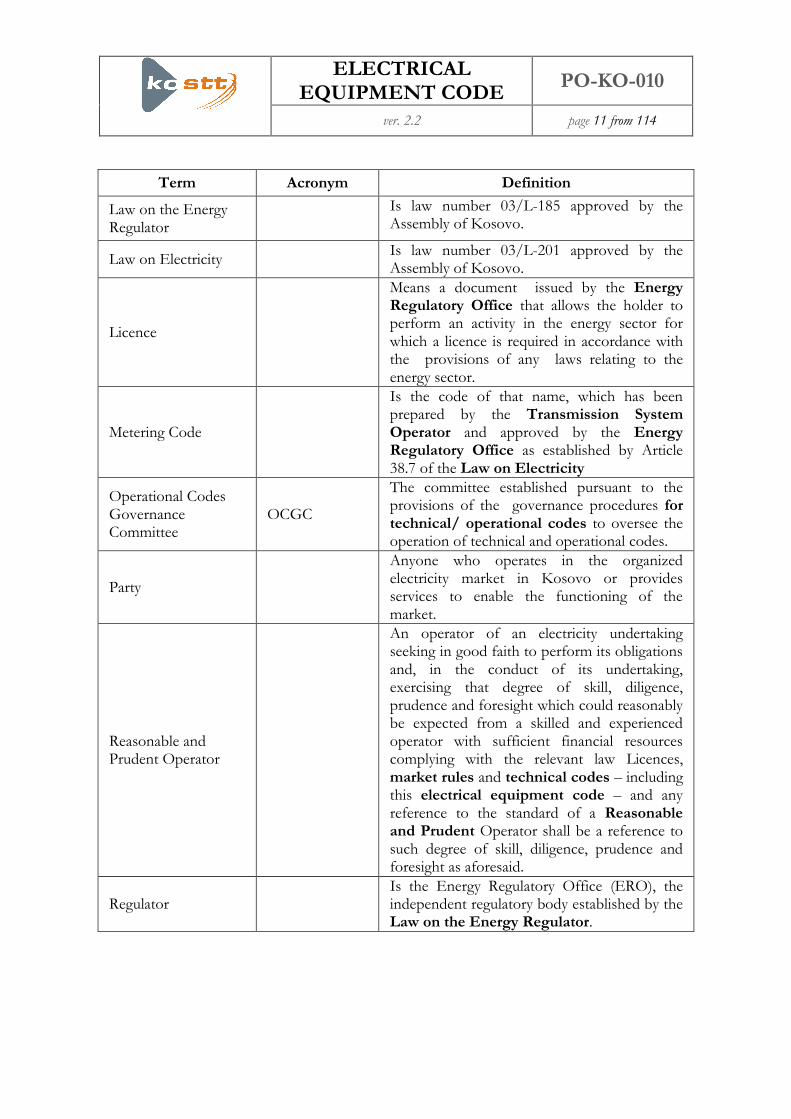
Term Acronym Definition
Law on the Energy Regulator
Is law number 03/L-185 approved by the Assembly of Kosovo.
Law on Electricity Is law number 03/L-201 approved by the Assembly of Kosovo.
Licence
Means a document issued by the Energy Regulatory Office that allows the holder to perform an activity in the energy sector for which a licence is required in accordance with the provisions of any laws relating to the energy sector.
Metering Code
Is the code of that name, which has been prepared by the Transmission System Operator and approved by the Energy Regulatory Office as established by Article 38.7 of the Law on Electricity
Operational Codes Governance Committee
OCGC
The committee established pursuant to the provisions of the governance procedures for technical/ operational codes to oversee the operation of technical and operational codes.
Party
Anyone who operates in the organized electricity market in Kosovo or provides services to enable the functioning of the market.
Reasonable and Prudent Operator
An operator of an electricity undertaking seeking in good faith to perform its obligations and, in the conduct of its undertaking, exercising that degree of skill, diligence, prudence and foresight which could reasonably be expected from a skilled and experienced operator with sufficient financial resources complying with the relevant law Licences, market rules and technical codes – including this electrical equipment code – and any reference to the standard of a Reasonable and Prudent Operator shall be a reference to such degree of skill, diligence, prudence and foresight as aforesaid.
Regulator Is the Energy Regulatory Office (ERO), the independent regulatory body established by the Law on the Energy Regulator.

ELECTRICAL EQUIPMENT CODE
PO-KO-010
ver. 2.2 page 12 from 114
Term Acronym Definition
Rule on the Resolution
of Complaints and
Disputes in Energy
Sector
A rule on dispute settlement procedure established by Energy Regulatory Office in accordance with law on the energy regulator that provides the basis for resolving disputes in the energy sector.
Governance
Procedures for
Technical/Operational
Code
Governance procedures for technical and operational codes issued by the regulator in accordance with article 14.2 (16) of the law on the energy regulator.
System User Is a natural or legal person supplying to, or being supplied by, a transmission system or distribution system.
Transmission
Means the transport of electricity on the high-voltage interconnected system with a view to its delivery to final customers or Distribution System Operators, but not including supply.
Transmission System Operator
TSO
A natural or legal person responsible for operating, ensuring the maintenance of the transmission system and the development of the transmission network, where applicable, its interconnections with other systems, and for ensuring the long-term ability of the system to meet reasonable demands for the transmission of electricity
Transmission System TS Is a combination of electricity power lines and electricity units of high voltage serving the transmission of electricity
ENTSO-E Is the European Network of Transmission Sys-tem Operators for Electricity.
2.1.1.2 In addition to special meanings contained in the Glossary and Definitions above,
within this document certain words and phrases have the following meanings:
(a) References to the masculine shall include the feminine and references in the
singular shall include references in the plural and vice versa,
(b) Where this electrical equipment code specifies written information or written
confirmation to be given then any other suitable means of electronic transfer
ELECTRICAL EQUIPMENT CODE
PO-KO-010
ver. 2.2 page 13 from 114
that enables the recipient to retain the information – such as electronic mail or
FAX - fulfils this requirement,
(c) Except where explicitly stated otherwise all references to section shall be a
reference to a section in this electrical equipment code,
(d) Any reference to a law or regulation shall be a reference to that law or regulation
applicable in Kosovo or, following the replacement of that law or regulation the
new law or regulation from the date it comes into force.
3 Service Conditions
3.1 General
3.1.1.1 Plant, equipment and apparatus should be suitable for operation under the following
normal and special service conditions.
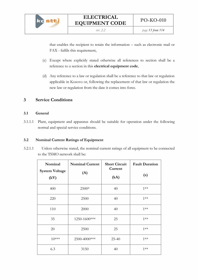
3.2 Nominal Current Ratings of Equipment
3.2.1.1 Unless otherwise stated, the nominal current ratings of all equipment to be connected
to the TSMO network shall be:
Nominal
System Voltage
(kV)
Nominal Current
(A)
Short Circuit Current
(kA)
Fault Duration
(s)
400 2500* 40 1**
220 2500 40 1**
110 2000 40 1**
35 1250-1600*** 25 1**
20 2500 25 1**
10*** 2500-4000*** 25-40 1**
6.3 3150 40 1**

ELECTRICAL EQUIPMENT CODE
PO-KO-010
ver. 2.2 page 14 from 114
* In the specific cases and special conditions with verification from TSO analysis, can be
adapted Current value of 3150A.
** In the specific cases and special conditions with verification from TSO analysis, can be
adapted the time value of 3sec..
*** In specific cases, regarding from nominal power of transformers 110/10(20) kV, as well
as in cases when it is required parallel work of transformers at 10 kV side, as well as base on
calculations of the level of fault currents.
clarification:
- The voltage levels 10 kV, 6.3 kV referred to the self consumption of 220/110 kV
substations, respectively tertiary winding voltage of 220/110 kV autotransformers.
- The voltage levels 35 kV, 10 kV and 10(20) kV, referred to the secondary side of
transformers 110/x kV, with standardized nominal power: 63 MVA, 40 MVA, 31.5 MVA
and 20 MVA
3.3 Normal Service Conditions
3.3.1.1 Controlgear and other equipment housed outdoors in association with high or
medium voltage plant shall have a degree of protection of at least IP 54 as defined in
IEC 60529.
3.3.1.2 Controlgear and other equipment housed outdoors in association with high or
medium voltage plant shall have a degree of protection of at least IP 41 as defined in
IEC 60529.
3.3.1.3 All plant, equipment and apparatus should have a degree of protection of at least
IP2X under normal operating conditions should include, opportunity for the local
operation of equipment with cabinet doors open.
3.3.1.4 Normal service conditions, as defined in IEC 60694, should be applicable. Where an
alternative exists in IEC 60694, the following selection of values has been made, and
together with the fixed values in IEC 60694 are the values required by the TSO.

ELECTRICAL EQUIPMENT CODE
PO-KO-010
ver. 2.2 page 15 from 114
3.3.2 Indoor Plant
3.3.2.1 Indoor temperature minus -5°C.
3.3.3 Outdoor Plant
3.3.3.1 The following air temperatures apply:-
(a) Maximum ambient temperature 40°C
(b) Maximum daily average ambient temperature 30°C
(c) Annual average ambient temperature 20°C
(d) Minimum ambient temperature -30°C
3.3.3.2 The maximum wind (gust) velocity is 50 meters per second.
3.3.3.3 The humidity is low in summer and high in winter.
3.3.3.4 Atmospheric pollution
(a) In Kosovo, pollution is generally medium.
(b) In certain places pollution is heavy or very heavy and, if this applies, it will be
stated in the tender documentation.
3.3.3.5 Ice Coating Class 20 mm.
3.3.3.6 Seismic activity between VII and VIII on the Modified Mercaly Intensity Scale is
likely to be encountered in Kosovo. All civil works must be constructed with this level
of seismic activity considered in the design works. Any supplier proposing to provide
electromechanical equipment shall demonstrate that it is designed to resist earthquake
loadings resulting in the confirmation report from the competent institution related to
the seismic intensity of earthquakes at specific location.
3.3.4 Protection and Control Equipment Operating Environments
3.3.4.1 The operating environment for Equipment, such as control and protection, is
categorized in the following table. Equipment shall be suitable for operation in adequate

ELECTRICAL EQUIPMENT CODE
PO-KO-010
ver. 2.2 page 16 from 114
environment including the ability to maintain critical functions in the event of failure of
environmental control facilities such as air conditioning.
Class Sitting Conditions Class according
to IEC 60654-1
Ambient
Temperature
Range
Relative
Humidity
Limits
1 Rooms with air conditioning A1 +18 to +27°C 20 to 75%
2
Control rooms and
Equipment rooms which are
not with conditioning air
B3
-5 to +55°C 5 to 95%
3
Plant areas, rooms and
block houses away from
high temperature plant and
subject to greater extremes
than Class 2
N/A
-5 to +40°C 5 to 95%
4 Outdoors ambient C2 -30 to +40°C 10 to 100%
The ambient temperature maxima assume negligible solar gain and negligible localised
temperature excursions i.e. adequate ventilation. The validity of these assumptions must be
considered, and confirmed, at the application stage.
For ventilated Equipment the ambient temperature is defined as being the free air temperature
existing at a point level with the top of the Equipment.
3.3.5 Fault Clearance
3.3.5.1 Plant and Equipment shall be suitable for operation under the following conditions:

ELECTRICAL EQUIPMENT CODE
PO-KO-010
ver. 2.2 page 17 from 114
Nominal Voltage
(kV)
Target fault
interruption time of
main in-feeding
circuit (ms)
Target total fault
clearance time (all
infeeds) (ms)
Target backup
clearance time (ms)
400 85 100 250
220 100 120-140 250-400
110 140 120-140 250-400
35 150
10 (20) 150
10 or 6.3 75 n/a n/a
3.3.5.2 In the event of a circuit-breaker failure, circuit-breaker fail protection shall trip all
necessary adjacent circuit-breakers that supply a fault infeed within a target fault
clearance time less than 300 ms.
3.3.6 Multi-pole Opening/Tripping and Auto-reclosing
3.3.6.1 Plant and equipment shall be suitable for simultaneous three-phase opening/tripping
and simultaneous three-phase auto-reclosing on overhead line feeder circuits.
3.3.7 Special Service Conditions
3.3.7.1 Plant & Equipment shall be suitable for operation in a pollution environment as
defined in the following table:

ELECTRICAL EQUIPMENT CODE
PO-KO-010
ver. 2.2 page 18 from 114
Insulation
IEC 60815 Pollution Class IEC 60507 Salt Fog
Withstand Test Specifi-
cation1 kg/m3
Indoor I No test withstand re-
quired
Outdoor III 80
Outdoor (special) IV >160
Outdoor Horizontal III& IV 80
3.3.7.2 External insulation shall be in accordance with the relevant requirements and
recommendations of IEC 60815.
3.3.7.3 For ceramic insulation, test conditions to prove this performance level shall be as
defined in the tables in sections 3.3.7.1 and the following table of test voltage levels for
pollution, salt fog and heavy wetting tests. Service experience offered in lieu of artificial
pollution testing shall be identical to that detailed for composite insulation.
Rated Voltage of
Insulation (kV) 420 245 123 38 12 (24)
Test Voltage (phase to
earth) (kV) 242 142 71 21.9 6.6 (13.8)
Test Voltage (phase to
phase) 420 245 123 38 12 (24)
Test Voltage for other
Insulation (as per IEC
60060)
Represents the maximum power frequency voltage to which the
insulation may be stressed in service. For insulation enclosing a
switchgear interrupting gap, or if insulation is specified for
enclosures for isolating gaps, or for insulation connected in
parallel with such an interrupting or isolating gap, this test
voltage shall be the out-of-phase voltage.

ELECTRICAL EQUIPMENT CODE
PO-KO-010
ver. 2.2 page 19 from 114
3.3.7.4 Insulation, including composite insulation, should comply with the requirements for
minimum specific creepage as specified in IEC 60815.
3.3.7.5 Ceramic insulation for vertical application meeting the following criteria is deemed to
meet the requirements of the tables in sections 3.3.7.1 and 3.3.7.3 without further
testing.
3.3.7.6 Phase-to-phase AIS solid external insulation is not acceptable.
3.3.7.7 The application of an anti-pollution palliative coating to the external surface of
ceramic insulation in order to satisfy the requirements of this specification is not
acceptable.
3.3.7.8 Products consisting of internally graded insulation contained within an external AIS
insulating enclosure or weather-shield, such as bushings, instrument transformers or
grading capacitors, shall be considered a single item for the purposes of pollution and
heavy wetting tests where required.
3.3.7.9 Phase to earth insulation connected in parallel and having a shed-to-shed separation
distance of less than 0.5 times the phase-to-earth clearance, shall be considered as a
single item for the purposes of pollution and heavy wetting tests.
3.3.7.10 Horizontally oriented insulation and insulation intended for mounting > 15° from the
vertical shall meet the pollution and heavy wetting requirements in its intended
orientation.
3.3.7.11 The insulation shall be mounted at the orientation intended for service during
pollution and heavy wetting tests.
3.3.7.12 Composite external insulation shall be supported by satisfactory evidence detailing the
suitability of the insulation for the intended site.

ELECTRICAL EQUIPMENT CODE
PO-KO-010
ver. 2.2 page 20 from 114
4 Substations
4.1 Technical Requirements for Substations Connected to the Transmission System
4.1.1.1 This Section covers all types of substations with equipment installed for use on 10(20)
kV, 35 kV, 110 kV, 220 kV and 400 kV of 50 Hz systems. Substations operating at other
nominal system voltages are expected to comply with the general provisions of this
document. It is applicable to both open-terminal air-insulated (AIS) and metal-enclosed
gas-insulated (GIS) substation constructions and covers equipment operated at lower
voltages on the same substation site. It is applicable to new construction and extensions
to existing installations and all TSO owned or operated plant and apparatus wholly
within the substation and not covered more specifically by other technical requirements
is within the scope of this document.
4.2 General Requirements
4.2.1 Designing For Safety
4.2.1.1 TSO has declared its commitment to safety and therefore intends that its substations
are as safe an environment as is reasonably practicable. This specification contains many
detailed requirements intended to ensure safety however, due to the complex nature of
substation design and construction, it is accepted that no single specification or suite of
specifications can guarantee to address all potential dangers in the best manner. TSO
believes it essential that its suppliers join with TSO in a collaborative manner to ensure
a “best practice” approach to substation design safety at all times. In particular
constructional issues such as tripping hazards, sharp edges, labelling and poor access
which are difficult to specify effectively should be eliminated wherever possible in the
design.
4.3 Legal Requirements
4.3.1.1 The manner in which plant and equipment is designed and installed as a system shall
allow that system and its components to be operated and maintained in accordance with
all relevant laws and regulations.
4.4 Environmental Impact
4.4.1.1 The siting and design of new substations shall take into account the best practice
approach developed by the networks committee of eurelectric, in their report “Public

ELECTRICAL EQUIPMENT CODE
PO-KO-010
ver. 2.2 page 21 from 114
Acceptance for new transmission overhead lines and substations” reference 2003-200-
0005.
4.5 Design Life of Installations
4.5.1.1 The substation installation including busbars, connections, insulators, structures
foundations and all other infrastructure shall be designed for a life of 40 years subject to
periodic preventive maintenance being carried out in accordance with the instructions of
manufacturers or suppliers.
4.6 Operational Access
4.6.1.1 Access, suitable for use by an unaccompanied person, shall be provided to the
isolation facilities of each isolator and earthing switch including any locking device. The
isolation facilities or locking devices shall be between 1 m and 1.8 m above ground or
floor level or above a platform provided for access and shall be not further than 750
mm horizontally from the edge of a platform.
4.6.1.2 Access above ground level shall be from mobile or fixed platforms (although fixed
platforms may be accessed by ladder). Where movement of equipment within the
substation would be restricted by the presence of ladders it is acceptable that these are
removable. Removable ladders and mobile platforms shall be easily handled and used on
the finished substation surface by one person. Ladders and permanent platforms shall
comply with relevant parts of ISO 14122 and their arrangement shall be approved by
TSO.
4.7 Maintenance Requirements
4.7.1.1 The substation layout and surfaces shall be adequate to allow the access and use of
any powered access equipment, cranes or similar equipment which may be required for
foreseeable maintenance activities Access suitable for gas handling equipment shall be
provided to all equipment containing SF6.
4.7.1.2 Roads shall be provided to access substation main buildings, relay rooms and heavy
items of plant (e.g. transformers) and shall be to a standard consistent with that of the
rest of the substation site. All other surfaces shall also be constructed to a standard
consistent with the rest of the substation site.

ELECTRICAL EQUIPMENT CODE
PO-KO-010
ver. 2.2 page 22 from 114
4.8 Interlocking (Conditions of operation)
4.8.1.1 Substations shall be provided with a full interlocking scheme as detailed in section 8.
4.9 Current Transformers
4.9.1.1 The accommodation of current transformers shall be as specified in section 5.26 The
location of current transformers shall be as specified in section 5.27.
4.10 Switchgear Secondary Isolation
4.10.1.1 Isolation facilities shall be accessible from ground level or from fixed platforms and
shall permit the application of isolation procedures.
4.11 Voltage Transformer Secondary Isolation
4.11.1.1 Voltage transformer secondary isolation links, or equivalent means of positive
isolation, shall be provided in a separate isolation box mounted between 1 m and 1.8 m
above substation floor or access platform level. The door of the isolation box shall be
capable of being locked using a padlock with a hasp having a 5 mm diameter and 30
mm long.
4.12 Earthing
4.12.1.1 At every connection point, the system user’s earthing system shall be integrated
with that of TSO’s substation earthing system and shall, as a minimum, meet the same
design and installation standards as TSO’s earthing system.
4.13 Equipment Identification
4.13.1.1 Labels shall be provided to allow unambiguous identification of all plant and
equipment and of associated operating facilities and points of isolation. The following
are required:
(a) Each circuit-breaker, isolator and earthing switch mechanism box shall carry a
label giving the operational reference of the device.
(b) Each pressure gauge or pressure readout device shall carry a label identifying the
parameter it is monitoring.

ELECTRICAL EQUIPMENT CODE
PO-KO-010
ver. 2.2 page 23 from 114
(c) Each valve (including self-sealing gas filling valves) shall carry a label identifying
its function.
(d) Each SF6 filling valve shall be provided with a label identifying the mass of gas
contained within the gas compartment to which it is fitted (at normal filling
density). The volume of the compartment and normal filling density shall also be
marked.
(e) Each control handle or switch for plant operation shall carry a label identifying
its function.
(f) Each point of LV isolation associated with plant shall carry a label identifying its
function.
(g) Each cabinet, cubicle or kiosk shall carry a label identifying all of the equipment
contained within it.
4.13.1.2 Labels shall be sufficiently durable for the application and the environment in which
they are to be used taking account of the expected operational lifetime of the
equipment. They shall remain in place and legible for the design lifetime of the
equipment.
4.13.1.3 The fixing of labels shall not compromise the degree of protection (IP rating) of the
equipment.
4.13.1.4 All pipework shall be identified in accordance with BGV A 8.
4.14 Secondary Equipment
4.14.1.1 Electronic equipment shall be located in accommodation commensurate with its
environmental performance, which is classified in section 3.3.4.1.
4.14.1.2 Light current accommodation shall meet the requirements of section 3.3.4.1, Class 3
under all ambient conditions.
4.14.1.3 Fixed heating shall be thermostatically controlled. Where no fixed heating is provided,
provision shall be made for raising the air temperature in the vicinity of all equipment
associated with any one circuit to 16oC without causing condensation on the equipment.
4.14.1.4 All panels housing secondary equipment which are sited in equipment rooms or
accommodation shared with equipment owned by other users shall be padlockable. All
ELECTRICAL EQUIPMENT CODE
PO-KO-010
ver. 2.2 page 24 from 114
panels housing metering equipment shall also be sealable in accordance with the
requirements of the metering code.
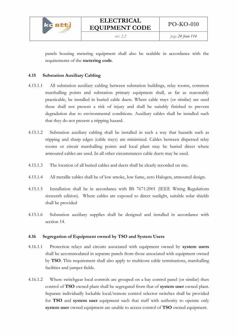
4.15 Substation Auxiliary Cabling
4.15.1.1 All substation auxiliary cabling between substation buildings, relay rooms, common
marshalling points and substation primary equipment shall, as far as reasonably
practicable, be installed in buried cable ducts. Where cable trays (or similar) are used
these shall not present a risk of injury and shall be suitably finished to prevent
degradation due to environmental conditions. Auxiliary cables shall be installed such
that they do not present a tripping hazard.
4.15.1.2 Substation auxiliary cabling shall be installed in such a way that hazards such as
tripping and sharp edges (cable trays) are minimised. Cables between dispersed relay
rooms or circuit marshalling points and local plant may be buried direct where
armoured cables are used. In all other circumstances cable ducts may be used.
4.15.1.3 The location of all buried cables and ducts shall be clearly recorded on site.
4.15.1.4 All metallic cables shall be of low smoke, low fume, zero Halogen, armoured design.
4.15.1.5 Installation shall be in accordance with BS 7671:2001 (IEEE Wiring Regulations
sixteenth edition). Where cables are exposed to direct sunlight, suitable solar shields
shall be provided
4.15.1.6 Substation auxiliary supplies shall be designed and installed in accordance with
section 14.
4.16 Segregation of Equipment owned by TSO and System Users
4.16.1.1 Protection relays and circuits associated with equipment owned by system users
shall be accommodated in separate panels from those associated with equipment owned
by TSO. This requirement shall also apply to multicore cable terminations, marshalling
facilities and jumper fields.
4.16.1.2 Where switchgear local controls are grouped on a bay control panel (or similar) then
control of TSO owned plant shall be segregated from that of system user owned plant.
Separate individually lockable local/remote control selector switches shall be provided
for TSO and system user equipment such that staff with authority to operate only
system user owned equipment are unable to access control of TSO owned equipment.

ELECTRICAL EQUIPMENT CODE
PO-KO-010
ver. 2.2 page 25 from 114
4.16.1.3 Facilities provided for substation level control of system users’ equipment shall have
no facilities to operate TSO owned equipment. Any electrical/mechanical supplies
which are provided by TSO to system users’ equipment shall be equipped with
segregated, clearly labelled isolation facilities. Auxiliary supply (48V dc, 110V dc and
400/220V ac) isolation facilities shall be located in the equipment local control cubicle
(LCC) or, where installed in a common panel, shall be clearly segregated from isolation
facilities for TSO owned equipment. LCCs and common panels should be sited in areas
to which access will be permitted to non-TSO staff.
4.16.1.4 400V ac supplies to significant system user loads, such as transformer coolers, shall
be supplied from separate circuits on the substation LVAC1 supplies board and
provision shall be made for the installation of metering. Isolation facilities shall be
provided at the load end of the circuit such that isolation at the LVAC board is not
normally required during maintenance.
4.16.1.5 Common compressed air, hydraulic or other motive power systems supplying both
TSO and system users’ equipment are unacceptable.
4.16.1.6 The ownership of equipment shall be clearly labelled particularly where TSO and
system users’ equipment or isolation facilities are located in close proximity.
4.17 Lifting Equipment
4.17.1.1 Lifting beams or fixed overhead travelling cranes of adequate capacity shall be
provided where their use is required to assist with maintenance, repair or dismantling of
switchgear. Fixed cranes shall not be provided in outdoor substations or indoor AIS
substations except where specifically required for maintenance or repair purposes.
Provision shall be made to inspect beams or cranes where required by regulation or for
insurance purposes and to fit lifting tackle.
4.18 Substation Facilities
4.18.1.1 As a minimum the following facilities shall be provided at all new 400 kV, 220 kV,
110/35/10(20) kV TSO owned by TSO.
1 LVAC – Low Voltage Alternating Current

ELECTRICAL EQUIPMENT CODE
PO-KO-010
ver. 2.2 page 26 from 114
(a) Adequate toilet and washing facilities for operation and maintenance staff taking
into account the company’s equal opportunities policies.
(b) Adequate lighting.
(c) Standby control rooms with provision to be equipped as a permit office and to
be used for on-site drawing/record storage. At indoor GIS substations access to
the control room shall not be through the switchgear hall and the room shall
prevent ingress of SF6 decomposition products in the event of a switchgear
fault.
(d) At sites where SF6 gas-filled equipment is installed a standing area and suitable
water and drainage connections for a mobile changing/shower facility. Where
large volumes of SF6 are installed e.g. GIS substations, a fixed installation is
required.
(e) A small mess room with sink, worktop, electrical outlets and facilities for the
supply of drinking quality water.
(f) An equipment store (including earthing equipment storage facilities) / small
workshop.
(g) Vehicle parking.
4.19 Site Security
4.19.1.1 All equipment within the substation shall be installed further than 2 m from the
security fence.
4.20 Fire Protection
4.20.1.1 System users must install fire protection on their bays to the same standard as that
of the TSO substation site.
4.21 Disturbance Recorder
4.21.1.1 A disturbance recorder as specified by TSO shall be installed in each 400kV and
220kV substation.

ELECTRICAL EQUIPMENT CODE
PO-KO-010
ver. 2.2 page 27 from 114
4.22 General Requirements Applicable to AIS Substations
4.22.1 Electrical Clearances
4.22.1.1 The layout of AIS equipment shall ensure the integrity of the air space between live
parts and other conductors (whether earthed or at different potential) for the rated
voltage conditions for which the substation is designed. Where equipment
configurations have not been dielectrically tested in accordance with IEC 60694 then
minimum operational electrical clearances in accordance with the following table shall
be applied.
Nominal System
Voltage
(kV RMS)
BIL/SIL
(kV peak)
Phase to Earth
Clearance
(m)
Phase to Phase
Clearance
(m)
6.3 60 0.09 0.12
10 75 0.12 0.15
10 (20) 75 (125) 0.12 0.15
35 190 0.36 0.36
110 550 1.1 1.1
220 1050/900 2.1 2.1
400 1550/1425 2.6-3.4 4.2
BIL – Basic Insulations Levels
SIL – System Insulations Levels
The minimum clearance of 500mm is proposed to avoid problems of vermin and bird interference.
4.22.2 Safety Clearances/Distances
4.22.2.1 Safety to persons shall normally be achieved by the provision of adequate safety
clearance to live parts taking into account the need for maintenance, vehicular and
pedestrian access. Where adequate safety clearances to live parts cannot be maintained
without limiting access, barriers or fences shall be provided.

ELECTRICAL EQUIPMENT CODE
PO-KO-010
ver. 2.2 page 28 from 114
4.22.2.2 The safety clearances to be maintained in AIS installations are listed in the following
table:
Nominal System
Voltage
(kV RMS)
Safety Distance
(m)
Vertical Design
Safety
Clearance (m)
Horizontal
Design Safety
Clearance (m)
Insulation
Height
(Pedestrian
Access) (m)
6.3 0.8 3.2 2.3 2.4
10(20) 0.8 3.2 2.3 2.4
35 0.8 3.2 2.3 2.4
110 1.3 3.7 2.8 2.4
220 2.0 4.4 3.5 2.4
400 3.1 5.5 4.6 2.4
In this table, the minimum clearances are quoted and an appropriate additional allowance
should be made by the Supplier for constructional tolerances. The heading terms used mean:
Safety Distance: No part of the body or any object to should be able to infringe this
distance to exposed conductors operated at high voltage.
Vertical Design Safety Clearance is the minimum clearance from a live conductor to a
point to which pedestrian access is permitted. These figures are derived by adding the
'personal reach' (the vertical reach of a person with upstretched hand), which is taken to be
2.4 m, to the appropriate Safety Distance.
Horizontal Design Safety Clearance is the minimum distance between a live conductor
and any point at the same height where a person may stand. These figures are derived by
adding the horizontal reach of a person (taken to be 1.5m) to the appropriate safety clearance.
Where possible, the vertical design clearance should be applied in all directions.
Insulation height is the minimum clearance from the lowest insulation part of a support
insulator to a point where pedestrian access is permitted.

ELECTRICAL EQUIPMENT CODE
PO-KO-010
ver. 2.2 page 29 from 114
4.22.3 Clearances to Perimeter Fences
4.22.3.1 Exposed live conductors that cross perimeter fences shall, under worst-case
conditions, be at a height no less than for 110kV line is 3m for 220 kV is 3.75 and for
400 kV is 5 m
4.22.3.2 Exposed live conductors that do not cross perimeter fences shall be a distance at least
equal to the vertical design safety clearance as specified in section 4.22.2.2 (measured
horizontally) from a substation compound perimeter fence.
4.22.4 Clearance to Roadways
4.22.4.1 The minimum vertical clearance from exposed live conductors to internal substation
roadways or recognised maintenance access routes to which vehicular access is required
shall be the greater of:
a) Minimum height above ground of overhead lines as defined in the appropriate part of
the table in section 17.5.1.1, or
(b) Max vehicle height + 0.5m margin + Safety Distance
4.22.4.2 Where the latter criterion is used the maximum vehicle height used for the design
shall be clearly marked at all vehicular access points.
4.22.4.3 The horizontal clearance from defined roadways to exposed live conductors shall be
sufficient to ensure that:
a) the safety distance is not infringed by any part of a vehicle, and
b) the horizontal design safety clearance in the table in section 4.22.2.2 is
maintained from the driving and/or riding position of any vehicle taking
account of cases where the driving and/or riding position falls outside (above)
the envelope of the vehicle.
4.22.4.4 Lockable height barriers shall be provided at entrances to the substation and/or
within the substation to restrict access for vehicles exceeding the maximum height for
which unrestricted access is permitted.
4.22.5 Substation Profile
4.22.5.1 The height of the highest component of outdoor substations should be kept to a
practical minimum to achieve a low substation profile.
ELECTRICAL EQUIPMENT CODE
PO-KO-010
ver. 2.2 page 30 from 114
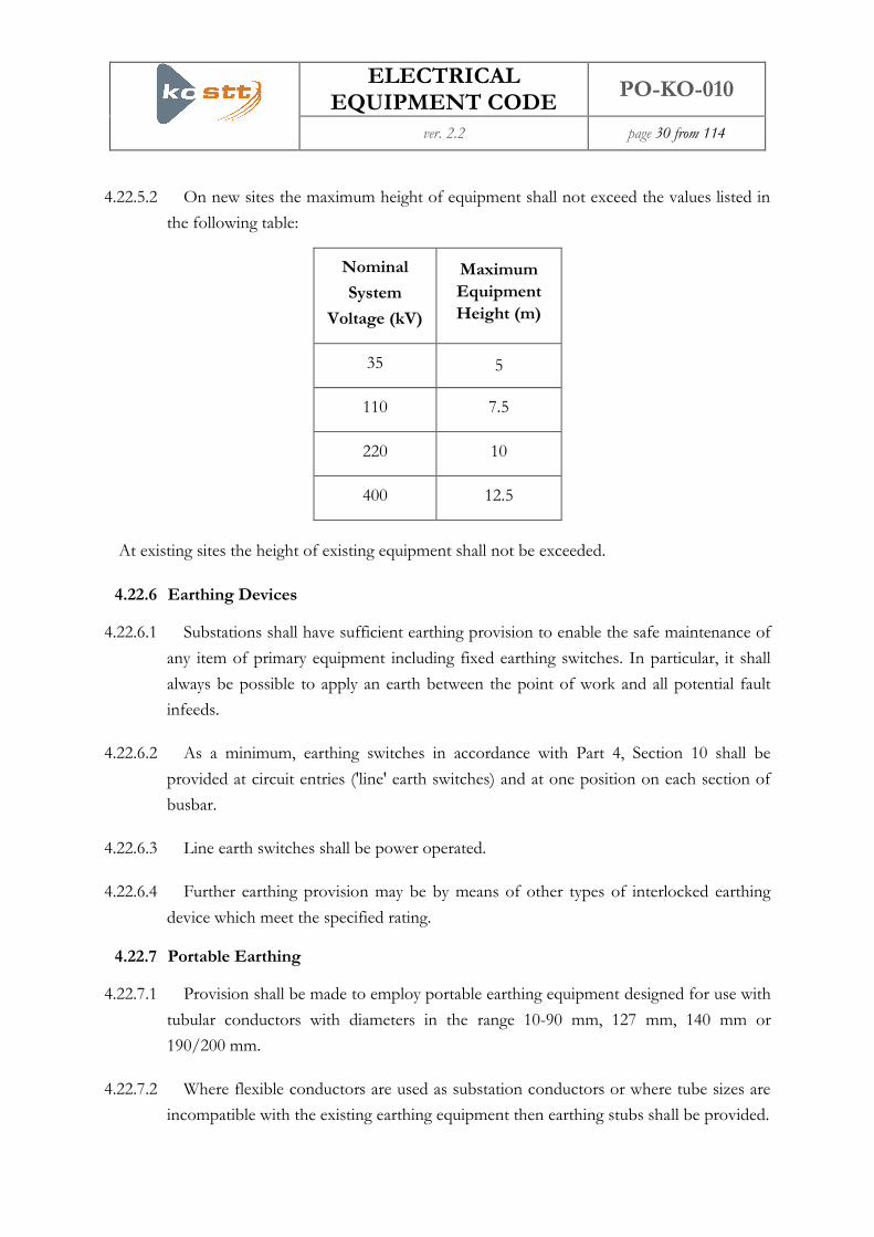
4.22.5.2 On new sites the maximum height of equipment shall not exceed the values listed in
the following table:
Nominal
System
Voltage (kV)
Maximum
Equipment
Height (m)
35 5
110 7.5
220 10
400 12.5
At existing sites the height of existing equipment shall not be exceeded.
4.22.6 Earthing Devices
4.22.6.1 Substations shall have sufficient earthing provision to enable the safe maintenance of
any item of primary equipment including fixed earthing switches. In particular, it shall
always be possible to apply an earth between the point of work and all potential fault
infeeds.
4.22.6.2 As a minimum, earthing switches in accordance with Part 4, Section 10 shall be
provided at circuit entries ('line' earth switches) and at one position on each section of
busbar.
4.22.6.3 Line earth switches shall be power operated.
4.22.6.4 Further earthing provision may be by means of other types of interlocked earthing
device which meet the specified rating.
4.22.7 Portable Earthing
4.22.7.1 Provision shall be made to employ portable earthing equipment designed for use with
tubular conductors with diameters in the range 10-90 mm, 127 mm, 140 mm or
190/200 mm.
4.22.7.2 Where flexible conductors are used as substation conductors or where tube sizes are
incompatible with the existing earthing equipment then earthing stubs shall be provided.

ELECTRICAL EQUIPMENT CODE
PO-KO-010
ver. 2.2 page 31 from 114
4.22.7.3 Points for attachment of the earth end of portable earthing leads shall be provided at
each switchgear structure. Each portable earthing lead attachment point shall be
connected to the substation earthing mat by a fully rated conductor system. Allowance
shall be made for the attachment of sufficient leads at each attachment point to match
the switchgear rating.
4.22.7.4 For primary earthing TSO require fully rated earthing capability to be applied in a
single operation. Where portable earthing leads are used to achieve primary earthing,
consideration should be given to safe application positions and compliance with good
industry practice regarding manual handling.
4.23 General Requirements applicable to GIS Substations
4.23.1 Buildings
4.23.1.1 GIS installations comprising two or more circuit breakers shall be housed in a
building. The building shall be of minimum life cycle cost construction consistent with
environmental and planning requirements. Fixed cranes shall be provided in indoor GIS
substations unless the supplier can demonstrate that they are not required for
dismantling or removing any part of the substation for maintenance or repair purposes.
4.23.2 AIS Connections
4.23.2.1 AIS connections associated with GIS substations shall meet the requirements detailed
in Section 4.21.
4.23.2.2 Line earth switches shall be of AIS design where reasonably practicable.
4.23.3 Portable Maintenance Earthing Devices (PMEDs)
4.23.3.1 Two three-phase sets of each type of PMED employed shall be supplied.
4.23.4 Gas service connections
4.23.4.1 A diagram of the gas system shall be displayed at the Local Control Cabinet or at any
point where gas service connections are grouped together.
4.23.5 Pressure/Density Indication
4.23.5.1 All displays of pressure/density shall be readable from the substation floor level or
from access walkways.

ELECTRICAL EQUIPMENT CODE
PO-KO-010
ver. 2.2 page 32 from 114
4.23.6 SF6 Gas Alarm Scheme
4.23.6.1 An audible alarm scheme to warn operators of a major loss of SF6 gas shall be
provided in indoor substations. This shall operate at the low pressure alarm setting of
each gas zone.
4.23.6.2 Controls shall be provided at the substation control point to reset and isolate the
audible alarm. Visual indications shall be provided in the switchhouse to show that the
audible alarm is in service. Visual indications shall be provided outside the main
entrances to the switchhouse to indicate that the alarm has operated.
4.23.6.3 SF6 detection and alarms shall be installed in substations where a slow leak may
foreseeably result build up of gas e.g. in basement areas.
4.23.7 Location of Light Current Equipment
4.23.7.1 Equipment panels may be located in the switchgear building either adjacent to the
switchgear or in an annexe. Such equipment, together with its accommodation, shall
meet the requirements of Class IP 54 of IEC 60529.
4.24 Performance Requirements for all Switchgear
4.24.1 Jointing of Current Carrying Conductors
4.24.1.1 Jointing of Current Carrying Conductors shall be undertaken as detailed in section
4.26
4.24.2 Primary Equipment
4.24.2.1 Calculations or tests shall be performed to demonstrate the mechanical capability of
terminals for specified loading combinations of the conductor system in which the
equipment is to be applied.
4.25 Routine Tests at Site
4.25.1 Current Carrying Conductors
4.25.1.1 Where joints between current carrying conductors are made on site then the joint
electrical resistance shall be measured and recorded. The joints covered in this
document are all large and their electrical resistance is low. Values can range from as
little as 2 μΩ for large busbar connections to a few hundred micro ohms for small cable
connections. As even poorly made joints are likely to have a relatively low resistance, it

ELECTRICAL EQUIPMENT CODE
PO-KO-010
ver. 2.2 page 33 from 114
is important to be able to make accurate measurements of resistance to detect joints that
are not satisfactory for service.
4.26 Conductor Jointing in Substations
4.26.1 Introduction to Conductor Jointing
4.26.1.1 Within a substation there are many electrical connections ranging from busbars and
earthing joints down to small assemblies on electronic circuit boards. This section deals
with connections required to carry either primary load current or fault current or both.
The associated maximum permitted temperatures under these conditions are 90oC and
405oC (325oC for aluminium). It does not cover equipment contacts, contactors, and
sliding/moving contacts for which specific and detailed installation and maintenance
instructions exist. The integrity of busbar and earthing connections is essential for the
security and safety of the high voltage substation. They are heavily loaded and
temperatures at the connection interface are high such that degradation of poorly made
and maintained joints is likely.
4.26.1.2 Outdoor connections that operate under all weather conditions require protection to
avoid corrosion induced long-term degradation. The aim of this part of the document is
to provide guidance on good practice for conductor jointing in substations and it is
Informative rather than Normative in nature. It aims to promote a good understanding
of how to achieve high quality electrical connection and details typical problems
encountered within the jointing process. Particular emphasis is placed on bolted joints
for two reasons. Firstly, they can be less secure than joints which rely on fusion of
materials e.g. welding and secondly, many bolted joints are disconnected for
maintenance or to provide electrical isolation and thereby are at risk of being incorrectly
remade.
4.26.2 Jointing Guidelines
4.26.2.1 There is a wide range of jointing methods available but, without exception, their
effectiveness relies on trained people working to established procedures. Inadequately
trained workers or a disregard of the precise instructions is liable to be unsafe and result
in an inadequate connection. Where particular jointing instructions exist, they should be
followed, since they will normally have been developed and tested by the manufacturer
or supplier.

ELECTRICAL EQUIPMENT CODE
PO-KO-010
ver. 2.2 page 34 from 114
4.26.3 Preparation of Surfaces of Bolted Joints
4.26.3.1 The removal of oxide films and contamination and the creation of the rough sharp
peaks needed for good electrical contact shall be achieved by a combination of brushing
using a steel brush and abrasion by using aluminium oxide cloth grade 80. Aluminium
surfaces shall be subject to particularly diligent surface preparation.
4.26.3.2 To ensure consistent low resistance joints are achieved a suitable solvent shall be used
to clean dirty or greasy surfaces, any burrs around bolt-holes or edges shall be removed,
busbar or strip should be flat and any noticeable bowing or distortion should be
removed, a fresh strip of aluminium oxide cloth shall be used to abrade the mating
surfaces and each surface shall be coated with a thin layer of suitable grease for jointing.
Bolted joints that are working in transformer oil should be coated with Petroleum Jelly
as other greases may be chemically incompatible.
4.26.3.3 Since certain types of joint combinations can develop instability if operating at
continuous high temperature, for these types of joint, a suitable transition interface such
as the use of transition washers, shall be used, following the assembly instructions
provided by the manufacturer or supplier.
4.26.4 Preparation of Tinned or Plated Surfaces of Bolted Joints
4.26.4.1 Where the surfaces of bolted joints have been tinned or plated, dirty or greasy
surfaces shall be cleaned using a suitable solvent, any burrs around bolt-holes or edges
shall be removed, busbar or strip shall be confirmed to be flat and any noticeable
bowing or distortion shall be removed.
4.26.4.2 Except where nickel plating is used, plated surfaces shall not be prepared unless they
appear badly tarnished when a nylon brush shall be used to remove tarnish without
scratching the plating.
4.26.4.3 Nickel plated surfaces are likely to have a surface film which can inhibit good contact
if the contact pressure is low and this surface should be lightly and carefully abraded
with a fine oxide paper.
4.26.4.4 Each surface to be jointed shall be coated with a thin layer of a suitable grease for
jointing. Bolted joints that are working in transformer oil should be coated with
Petroleum Jelly as other greases may be chemically incompatible.

ELECTRICAL EQUIPMENT CODE
PO-KO-010
ver. 2.2 page 35 from 114
4.26.5 Assembly of Bolted Joints
4.26.5.1 After ensuring that nuts run freely on the bolts or studs, joints shall be assembled as
soon as possible after the surfaces have been prepared to minimise oxide growth and
contamination of the surfaces.
4.26.5.2 Before tightening, a check must be undertaken to ensure the correct sized washers
have been placed under the bolt head and nut. Tightening shall be undertaken using a
torque wrench set for the size and grade of bolt material.
4.26.5.3 If the electrical connections allow, the resistance of the joint shall be measured and
checked against the resistance of the same length of un-jointed bar to ensure that the
resistance of the joint is less than the resistance of the same length of un-jointed bar.
4.26.5.4 Outdoor joints shall be protected against corrosion by smearing a liberal amount of
suitable grease around the joint edges of similar metal joints. If the metals are dissimilar
e.g. aluminium bolted to copper, the whole area of overlap shall be protected with
anticorrosion tape or a preinstalled heat shrink sleeve packed with a suitable grease. For
complex shapes, mastic may be used. Copper to aluminium connections shall not be
installed with the copper above the aluminium as copper salts can drain down and cause
electrolytic action.
4.26.6 Service Performance of Bolted Joints
4.26.6.1 Bolted joints prepared and assembled in accordance with the above recommendations
should give a long and trouble-free life making continuous monitoring unnecessary.
However, joints which carry high continuous or cyclic currents or which experience
mechanical disturbance, vibration or shock may be susceptible to some degradation and
a consequent increase in electrical resistance. Overheating may result. Measurement of
joint temperatures using an infrared camera or measurement of joint resistance can be
used to ascertain the condition of current carrying joints. A joint resistance greater than
the resistance of the same length of unjointed conductor is a cause for further
investigation and, if possible, a comparison should be made with the resistance of
similar joints and with commissioned resistance values.
4.26.7 Gas Shielded Electric Arc Welded Joints (MIG – TIG)
4.26.7.1 Welding of copper, aluminium and steel can produce efficient and compact joints and
is useful for jointing tubular conductors and conductors of different cross-sections.
Effective jointing relies on correct procedures being followed and appropriate training.

ELECTRICAL EQUIPMENT CODE
PO-KO-010
ver. 2.2 page 36 from 114
Where this technique is employed, particular attention must be paid to the effective
tenting of the work area to ensure a relatively draught free environment to prevent the
gas shield being broken and the resultant risk of porous or oxidised welds. Measurement
of the resistance of completed joints is unnecessary since the electrical contact area is
relatively large but sample testing of completed joints should be undertaken in
accordance with BS EN 1320:1997.
4.26.8 Fusion Electric Arc Welding, Gas Brazing and High Temperature Soldering
4.26.8.1 These techniques may be used to join copper, aluminium and certain other materials.
Since during fillet or lap jointing of aluminium the fluoride flux used during the jointing
process is liable to entrapment between contracting metal surfaces, this technique
should be avoided. Similarly, electric arc fusion welding of copper should be avoided as
porosity and brittle inter-metallic formations impair the mechanical properties of the
joint.
4.26.8.2 Copper/aluminium jointing must be undertaken carefully with the provision of a
0.75-1mm layer of silver brazing alloy to the weld area of the copper as this is
metallurgically compatible with both copper and aluminium. Jointing can then be
performed by direct fusion welding using conventional aluminium-silicon filler metal.
4.26.8.3 Gas brazing may be used to joint copper to rebar steel or wrought iron. Joint
preparation and cleanliness are essential to ensure that the molten filler metal flows over
the complete joint area. However, because joint quality is not easy to determine since
the electrical resistance will normally be very low a fracture test conducted with dynamic
sensible strokes (3 off) applied from a hammer must be used to check that the joint is
sound.
4.26.9 Explosive Jointing / Cold Pressure Welding
4.26.9.1 Because of difficulties achieving the required standard of consistency in the on site
preparation of the surfaces to be jointed these methods of jointing are not acceptable.
4.26.10 Compression Jointing
4.26.10.1 This method may be used to join solid or circular conductors provided that:
(a) the dies, compression tools and the ferrules or lugs are from the same
manufacturer,

ELECTRICAL EQUIPMENT CODE
PO-KO-010
ver. 2.2 page 37 from 114
(b) the conductors are cleaned in accordance with the instructions issued by the
manufacturer of the compression fitting,
(c) the correct number and order of compression bites by the die are used,
(d) the correct pressure is applied to the die from the hand or hydraulic tool.
4.26.10.2 Where greasing of the conductor is specified in the manufacturer’s instructions to
enhance stability and inhibit corrosion, this must be undertaken since large compression
joints used on down-droppers from an overhead line entry are particularly susceptible to
inadequate greasing of the barrel allowing water to drain down into the joint and set up
a corrosive cell.
5 Switchgear
5.1 General Technical Requirements
5.1.1.1 Switchgear shall have an anticipated asset life of not less than 40 years and shall
comply with all mandatory requirements of IEC 60694. Records shall be kept of all time
and duty based maintenance requirements and any refurbishment activity required to
achieve the anticipated asset life.
5.1.1.2 Provision shall be made for condition monitoring, diagnostics and site testing. Where
these facilities are integral to the switchgear they shall not reduce the integrity of the
prime function of the switchgear or that of neighbouring switchgear.
5.1.2 Compressed Gas
5.1.2.1 If compressed gas is used for arc extinction or operation, then abnormal gas system
condition lock-out devices shall be fitted and instruments and alarms shall be provided
to ensure safe and reliable operation of all compressed gas systems.
5.1.2.2 Alarm facilities shall indicate falling gas density/pressure and operate at a higher level
than the low gas density/pressure lockout devices. Remote indication or alarm of
density/pressure recharging equipment failure, abnormal gas system conditions and low
density/pressure lockout shall be available.
5.1.2.3 Provision shall be made for the connection of equipment for monitoring of the rate
of change of gas density/pressure of insulation and interruption systems.
ELECTRICAL EQUIPMENT CODE
PO-KO-010
ver. 2.2 page 38 from 114
5.1.2.4 The function of the various components of the gas system shall be clearly identified
at the switchgear. Different gases or different conditions of the same gas shall be
identified by colour on pipework, vessels and diagrams. The colour shall conform to the
standard colours for gases in BGV A 8 or BS 1710. If it is necessary to use white
pipework to reduce the effect of radiated heat then clear colour code marking will be
applied at regular intervals to indicate the gas contained.
5.1.3 Operating Mechanisms and Enclosures
5.1.3.1 Local control and monitoring equipment shall be accommodated at the switchgear
that it controls. Enclosures shall be clearly labelled to indicate the apparatus it contains
and the switchgear controlled by that apparatus.
5.1.3.2 Local controls shall be located at ground level (if indoors, at the switchgear access
level) and indication of the operational position of the switchgear being controlled shall
be unambiguous and clearly visible from that level.
5.1.3.3 Switchgear with power operated mechanisms shall be provided with means of locally
initiating closing and opening, and of selecting local/remote control. Three phase
switching devices with separate phase mechanisms shall be locally controllable from a
single point.
5.1.3.4 The maximum available number of auxiliary switches and the number normally pre-
allocated for use within the switchgear itself shall be clearly stated.
5.1.3.5 Auxiliary switches shall be positively driven in both directions.
5.1.3.6 Where anti-condensation heaters are fitted in cubicles of switchgear, they shall be
physically and electrically shrouded to protect operators from danger.
5.1.4 Outage Constraints
5.1.4.1 Switchgear design shall ensure that it is possible to safely perform foreseeable
maintenance and testing activities including replacement of any enclosure and any
necessary dismantling of equipment, circuit breaker timing, primary injection tests on
CTs and the construction and testing of substation extensions with the minimum of
circuit outages being required.
5.1.4.2 In any event, it shall be possible to perform the maintenance and testing activities
specified in 5.1.4.1 without the need to work adjacent to a gas compartment partition
that is under pressure on one side.

ELECTRICAL EQUIPMENT CODE
PO-KO-010
ver. 2.2 page 39 from 114
5.2 Technical Requirements for Gas Insulated Switchgear
5.2.1.1 All gas-insulated switchgear (GIS) shall comply with IEC 62271-203 and all
pressurised gas-filled enclosures shall comply with EN 50052, EN 50064 EN 50068,
and EN 50069 as appropriate. Cast resin partitions shall comply with standard EN
50089.
5.2.1.2 Fixed gas and hydraulic pipework shall be identified in accordance with BGV A 8 or
BS1710.
5.2.1.3 Earthing switches of class E1 as defined in IEC 62271-102 shall be provided on the
circuit side of each line isolator and at one position on each section of busbar. Earthing
switches installed at positions where the only means of dissipating trapped charge is by
closing the earthing switch shall be capable of remote operation.
5.2.1.4 Provision shall be made for fitting portable maintenance earthing devices (PMEDs)
where these are required to permit maintenance/testing as follows:
(a) To allow an earthing switch that would normally be the point of earthing to be
maintained.
(b) To earth cable terminations where disconnecting facilities are provided for cable
testing.
(c) To provide an earth connection where a section of busbar is removed.
(d) To provide an earth connection visible from the point of work.
5.2.1.5 The positions on the GIS at which PMEDs may be fitted shall be clearly identified
and switchgear design shall ensure that PMEDs that have been applied shall be clearly
visible.
5.2.2 SF6 Gas Service Connections
5.2.2.1 The gas service connection for each gas compartment shall be readily accessible
without the use of special access equipment.
5.2.2.2 A schematic diagram shall be provided showing the gas compartments within a bay
and their relationship to the primary plant of that circuit or busbar section.
5.2.2.3 Filling points shall be fitted with self-sealing valves.

ELECTRICAL EQUIPMENT CODE
PO-KO-010
ver. 2.2 page 40 from 114
5.2.2.4 A lockable arrangement to prevent unauthorised operation of the gas service valves
shall be provided at each filling point.
5.2.2.5 A permanently installed system for monitoring the gas pressure or density in each
compartment shall be provided. This system shall provide a visual indication of the gas
pressure or density in each gas compartment and be capable of detecting a gas loss
equivalent to 0.5 % of the gas compartment volume per annum and initiating gas
density alarms at user configurable trigger levels, locally and via the substation alarm
scheme.
5.2.2.6 It shall be possible to replace a pressure or density sensor without taking the
switchgear out of service and to temporarily block the density alarm signals from an
individual gas compartment so that grouped alarms are not initiated.
5.2.2.7 Where ‘low gas’ alarms are grouped, then it shall be possible to identify the section of
the substation that requires isolation from the system at the normal substation control
point.
5.2.2.8 Where leakage of gas from a higher pressure gas compartment to an adjacent lower
pressure gas compartment may result in operation of the pressure relief device of the
lower pressure compartment, the lower pressure compartment shall be fitted with a high
density alarm.
5.2.2.9 Provision for checking gas monitoring devices shall be achieved in such a way that
operation of as much of the alarm circuit as is reasonably practicable be confirmed. Safe
access for performing this check shall be provided.
5.2.2.10 Pressure relief devices shall be installed so as to eject debris away from normally
accessible areas and they shall be set to minimise danger to personnel.
5.2.2.11 The position of each gas compartment partition shall be clearly identified by fixing
clearly visible labels to the enclosure at each gas compartment partition showing the
identifier of the gas compartments at each side of that partition.
5.2.2.12 It shall be possible to undertake primary injection tests on all current transformers
without internal access to any gas compartment being required.

ELECTRICAL EQUIPMENT CODE
PO-KO-010
ver. 2.2 page 41 from 114
5.2.3 Partial Discharge Measurement
5.2.3.1 For GIS equipment for use at 220 kV and above, capacitive couplers for diagnostic
monitoring of the GIS equipment and transient voltage measurements shall be provided
in all phases at the following positions:
(a) The sealing ends of each cable connected circuit.
(b) The SF6 side of each transformer bushing.
(c) Adjacent to the SF6/air bushings of each circuit connected to AIS equipment.
(d) At intervals between these points such that all parts of the GIS shall be between
two couplers and that the required sensitivity specified in Clause 5.2.2.5 shall be
achieved.
5.2.3.2 To facilitate the use of couplers for in-service monitoring, coupler signal connections
shall be cabled so as to be accessible from ground or, if indoors, at switchgear access
level. Where located outdoors, test boxes conforming to IP65 of EN 60529 shall be
provided.
5.2.3.3 Signal cables between the couplers and test boxes shall be double screened co-axial
and signal cables and the connections shall be identified according to the associated
coupler and phase. The signal propagation time of each cable shall also be marked.
Signal connections shall be N series 50Ω sockets.
5.2.4 Performance Requirements
5.2.4.1 Voltage withstand between the point of isolation for cable testing and any parts of the
switchgear that remain connected to the cable termination during the test, shall be:
Nominal Voltage 10(20)kV 35 kV 110kV 220kV 400kV
15 minute withstand test
voltage to earth and, where
appropriate, between phases in
kV
16(32) 47.5 335 465 780

ELECTRICAL EQUIPMENT CODE
PO-KO-010
ver. 2.2 page 42 from 114
5.2.4.2 GIS circuit breakers and disconnectors shall be able to withstand two fully
asynchronous power frequency voltages applied to the opposite terminals of the same
pole when in the OPEN position with each voltage equal to the rated phase to earth
power frequency voltage when filled with the insulating gas at a pressure of 0 bar.
5.2.4.3 GIS equipment shall be able to withstand 1.5 times the rated phase to earth power
frequency voltage between its conducting parts and earth and, where appropriate,
between phases for a duration of 1 minute when filled with the insulating gas at a
pressure of 0 bar.
5.2.4.4 Enclosures shall be capable of withstanding an internal arc of rated short-time current
such that no external effect other than operation of the pressure relief device on small
gas compartments shall result for a duration not less than:
Nominal Voltage 10(20) kV 35 kV 110 kV 220 kV 400 kV
Internal arc withstand time (ms) 500 500 200 160 140
5.2.4.5 Enclosures shall be capable of withstanding an internal arc of rated short-time current
such that the resulting effect shall be limited to operation of the pressure relief device(s)
or the appearance of a hole, provided there is no ejection of fragmented parts for a
duration not less than:
Nominal Voltage 10(20)kV 35 kV 110kV 220kV 400kV
Internal arc withstand time (ms) 500 500 1200 500 300
5.2.4.6 Where GIS trunking falls within the line protection zone an internal fault would
normally result in a trip and auto reclose operation. If these requirements cannot be met
for the re-application of the fault, a mechanism for inhibiting the auto reclosing in the
event of probable gas failure must be provided. On equipment having three phases in a
common enclosure, allowance shall be made for the possibility of faults evolving to
include two or more phases.
5.2.4.7 Partitions shall withstand the differential pressures to which they may be subjected
during preventative or corrective maintenance. Where an adjacent gas compartment
contains live high-voltage conductors, a reduction in its gas pressure during maintenance
to limit the differential pressure across the gas compartment partition will not be
acceptable.

ELECTRICAL EQUIPMENT CODE
PO-KO-010
ver. 2.2 page 43 from 114
5.2.5 Sulphur Hexafluoride Gas (SF6)
5.2.5.1 New SF6 gas shall conform to IEC 60376 and recycled SF6 gas shall conform to IEC
60480.
5.2.5.2 At the time of commissioning of switchgear containing SF6 gas, the gas shall have a
moisture content of no greater than 25 mg/kg for indoor switchgear or 35 mg/kg for
outdoor switchgear.
6 Circuit Breakers
6.1.1.1 TSO specifies its requirements for circuit breakers primarily by reference to IEC
62271-100 and associated documents. This code defines the required enabling
parameters and additional technical requirements for circuit breakers connected to
TSO’s System and rated at 10(20) kV (2500 and 3150 A), 35 kV (1600A), 123 kV (2000
A and 2500 A), 245kV (2500 A) and 420 kV (2500 A). This section of the code defines
the performance requirements and testing for circuit breakers connected to TSO’s
system. It supports the more general conditions defined in the sections referring to
switchgear.
6.2 General Requirements
6.2.1 General Requirements for Circuit breakers
6.2.1.1 All mandatory requirements of IEC 62271-100 and IEC 60694 shall be met for the
specified rating.
6.2.1.2 The circuit breaker shall satisfactorily complete all initiated close and open operations.
6.2.1.3 In the event of a failure to latch in the closed position the circuit breaker shall open
fully and shall be capable of performing all switching and fault interrupting duties during
this opening operation.
6.2.1.4 In the event of opening immediately following a close operation and a continuous
close signal being maintained there shall not be repeated attempts to close the circuit
breaker.
6.2.1.5 All circuit breakers shall be fitted with a robust and reliable indicating drive system
capable at all times of giving a clear and unambiguous representation of the position of
the main contacts of the device. The indicating system shall be positively driven in both

ELECTRICAL EQUIPMENT CODE
PO-KO-010
ver. 2.2 page 44 from 114
directions. TSO accept the internationally agreed indication I/O in contrasting colours.
Alternatively, indicators inscribed CLOSED in white letters on Signal Red (BS 381C
Code 537) background and OPEN in white letters on Grass Green (BS 381C Code 218)
background are acceptable.
6.2.1.6 The density of the arc extinguishing and insulating media shall be monitored and
discrete low density alarm (or close lockout) and low density lockout levels shall be set.
These lockouts shall ensure that operation is prevented if the density is outside its
specified design criteria. Provision for local and remote indication of significant
reduction in density of arc extinguishing and insulating media shall be provided. This
indication shall be at a level in excess of the open (or general) lockout level however it is
acceptable for this indication to coincide with a close lockout level. The monitoring
system shall be such that any closing operations are only permitted if a subsequent
opening operation remains possible. These requirements may be modified where a
requirement for forced tripping is identified. Provision shall be made for low density,
close lockout and open lockout levels, as appropriate, to be remotely alarmed. Provision
shall be made for routine diagnostic monitoring, site testing and condition monitoring.
The circuit breaker in its normal operational state (i.e. with all access doors etc closed)
shall meet the pollution performance criteria associated with a degree of protection of
IP54. All moving parts which are readily accessible during normal operation of the
circuit breaker, including from the local operating position, shall have a degree of
protection of at least IP2X such that they are adequately guarded to prevent injury.
Where isolation facilities are provided between the main volume of any insulating or arc
extinguishing media and the associated monitoring equipment this isolation shall fail to
safety and it shall not be possible to put the circuit breaker into service with the
monitoring isolated.
6.2.1.7 Operating tolerances, including those for simultaneity of poles, shall be as specified in
IEC 62271-100 unless separately specified for special purpose applications such as
capacitor bank switching, single phase auto-reclose or shunt reactor switching.
6.2.2 General Requirements for Mechanisms and Stored Energy Systems
6.2.2.1 Circuit breakers shall be arranged for three-pole operation by powered mechanism or
mechanisms. The rated operating sequence in accordance with IEC 62271-100 shall be
O – 0.3s - CO – 3 min - CO.
6.2.2.2 Provision shall be made for local and remote indication that the stored energy system
has less than the specified minimum stored energy for a normal operating cycle, close-

ELECTRICAL EQUIPMENT CODE
PO-KO-010
ver. 2.2 page 45 from 114
open (CO). The close lockout shall be initiated. This 'stored energy system incorrect'
indication shall not be initiated due to normal operation of the circuit breaker.
6.2.2.3 Provision shall be made for local and remote indication that the stored energy system
has less than the specified minimum stored energy for normal opening. The open
lockout or, where required, a forced open operation, shall be initiated. This 'stored
energy system incorrect' indication shall not be initiated due to normal operation of the
circuit breaker.
6.2.2.4 Operating system lockouts shall be arranged such that if it is possible to close the
circuit breaker normally then opening is not prevented as a result of the energy
consumed during the preceding close operation.
6.2.2.5 In satisfying the above paragraph the maximum tolerance on setting of monitoring
devices and an allowance for drift and short time adiabatic change together with either
an ambient temperature change of up to 10oC or the normal loss of stored energy
during a two hour period, whichever has the greater effect, shall be taken into account.
Where practical the close lockout setting shall be equal to or less than 85 per cent of the
rated working pressure. Where a hydraulic system utilizes a compressed gas for energy
storage, the pre charge pressure of this gas related to the ambient temperature at the
time of pre charging shall be sufficient to prevent the initiation of a low gas alarm under
normal operating conditions when the ambient temperature falls to the minimum
specified in Section 3. Where such systems initiate lockouts following loss of the pre-
charge they shall also initiate appropriate alarms indicating the conditions.
6.2.2.6 Changes in ambient temperature of 20oC shall not initiate more than two operations
of any self contained stored energy replenishment systems as numerous operations
under such conditions may mask the presence of genuine energy loss. A replenishment
system excessive running time alarm, or equivalent, shall be fitted.
6.2.2.7 The operating level of safety/relief valves fitted to replenishment systems shall be set
with sufficient margin above the system replenishment cessation level to accommodate
an ambient temperature rise of 10oC
6.2.2.8 Facilities shall be provided to permit manual slow closing and slow opening of the
interrupter assembly and its drive mechanism. These facilities shall enable the state
(open or closed) of a circuit breaker to be changed following isolation from the high
voltage system. These facilities must be capable of being secured such that they can only
be used for maintenance purposes.

ELECTRICAL EQUIPMENT CODE
PO-KO-010
ver. 2.2 page 46 from 114
6.2.2.9 Means shall be provided to allow the stored energy system to be charged and
discharged when the circuit breaker is either closed or open without causing operation
of, or damage to, the circuit breaker. This requirement is waived for springs connected
directly to moving contacts, such as opening springs. Loss of stored energy from the
mechanism shall not cause the primary contacts to part.
6.2.2.10 Stored energy systems shall not be released due to vibration caused by normal
operation or other normal service phenomena.
6.2.2.11 Mechanisms incorporating springs for energy storage shall be provided with an
unambiguous indication of spring state (charged or discharged).
6.2.3 General Requirements for Control Schemes and Circuitry
6.2.3.1 If the opening circuit is initiated the closing circuit shall be rendered inoperative.
6.2.3.2 Operating mechanisms shall be provided with local, lockable initiation facilities for
closing and opening and for selection of local/remote control. These facilities shall be in
the immediate vicinity of the circuit breaker.
6.2.3.3 In the event of a failure to complete a closing operation involving poles having
independent drive mechanisms provision shall be made for automatic opening of poles
which have closed. Provision for a remote alarm indicating non-simultaneity of poles
shall be provided. This requirement shall take account of any intentional non-
simultaneity of poles.
6.2.3.4 Indications associated with the various monitoring requirements of this specification
shall be provided adjacent to the circuit breaker. These devices shall be capable of being
reset at this location. Provision shall be made for initiation of remote monitoring.
6.2.3.5 245 kV and 420 kV circuit breakers shall be provided with two opening releases per
operating mechanism. The opening releases shall be arranged for supply from
independent battery systems and shall have segregated circuits such that failure of one
device in a circuit does not prevent opening of the circuit breaker. System users
adopting an approach other than the use of independent battery systems must satisfy
the requirements of Section 4 with regard to the safety and security of TSO’s System at
the point of direct connection.
6.2.3.6 If the dc power supply is removed from either opening circuit of a circuit breaker
control scheme the closing circuit or mechanism shall be rendered inoperative.

ELECTRICAL EQUIPMENT CODE
PO-KO-010
ver. 2.2 page 47 from 114
6.2.3.7 Circuit-breaker opening coils and their associated opening circuits shall be provided
with a continuous supervision scheme that is functional regardless of the circuit-breaker
positional state (i.e.open or closed). This shall apply to both phase segregated and three
phase operated circuit breakers. The system shall be self-monitoring and shall provide
an alarm if the supervision system fails. The design of the supervision scheme shall be
such that failure does not cause the circuit breaker to operate. As well as the circuit-
breaker trip coils the system shall monitor all series connected links, auxiliary switches
and other components between the protection trip initiation contacts and the trip coils.
It shall be possible to remove a complete tripping circuit from service by use of suitable
isolation facilities. Such isolation facilities shall be monitored by the trip circuit
supervision scheme and be clearly and concisely labelled.
6.2.3.8 The alarm output of the supervision scheme shall not operate under normal circuit-
breaker operation or transient conditions (to overcome this, a delayed alarm output is
acceptable). The scheme shall not alarm for a persistent trip initiation signal with the
circuit-breaker open.
6.2.3.9 For circuit breakers with independent pole operating mechanisms it is preferred that a
single supervision circuit monitors the whole of each opening circuit or circuits where
duplicated. The alarm output shall not operate due to normal circuit breaker operations.
The system shall be self-monitoring and failure of a single component shall not cause
the circuit breaker to operate. The system shall be supplied as part of the circuit breaker
control equipment or be available as separate equipment for mounting on or in another
control cubicle.
6.2.3.10 Isolation facilities shall be provided for circuit breaker opening coils. These shall be
labelled appropriately. These facilities shall be such that the open circuit supervision
system shall detect isolation of the opening coils. In addition, the isolation facilities shall
be such that they can be secured against unauthorised reinstatement, preferably by a
lock and removable key system.
6.2.3.11 Provision shall be made to select the forced opening of a closed circuit breaker in the
event of the loss of stored energy to below the limiting conditions of the operating
system. Site specific application of such provision shall negate the need of any device
required to lock the mechanism closed under such loss of stored energy.
ELECTRICAL EQUIPMENT CODE
PO-KO-010
ver. 2.2 page 48 from 114
6.2.3.12 Electrical connectors used within the mechanism cabinet of a circuit breaker shall be
suitable for the mechanical duty imposed upon them and their integrity shall not be
compromised by operation of the mechanism.
6.2.4 Additional General Requirements for Special Purpose Circuit breakers for Capacitor Bank Switching
6.2.4.1 The control circuitry of all circuit breakers intended for capacitor bank switching shall
be capable of the addition of an approved controlled closing facility to facilitate
minimisation of closing transients when energising an earthed star connected capacitor
bank.
6.2.4.2 110kV circuit breakers shall be mechanically suitable for controlled closing with an
intentional 1/6th cycle (3.3 ms) delay between poles without compromising their basic
performance.
6.2.5 Additional General Requirements for Special Purpose Circuit breakers for Shunt Reactor Switching
6.2.5.1 The control circuitry of all circuit breakers intended for shunt reactor switching shall
be capable of the addition of an approved controlled opening facility to facilitate the
minimisation of re-ignition transients. The circuit breaker shall be mechanically suitable
for independent pole controlled opening without compromising its basic performance.
6.3 Performance Requirements
6.3.1.1 The Supplier shall state the density of the gaseous insulating medium at which the
circuit breaker can withstand two fully asynchronous power frequency voltages applied
to the opposite terminals of the same pole when in the OPEN position. Each voltage
shall be equal to the rated phase to earth power frequency voltage.
6.3.1.2 The Supplier shall also state the density at which the gaseous insulation can withstand
1.5 times the rated phase to earth power frequency voltage between its terminals and
earth.
6.3.1.3 Circuit breakers shall give a no-load sound pressure level of not greater than 90 dB
(linear) measured at a distance of 25 metres from the centre line of the circuit breaker in
the most disadvantageous direction.
6.3.1.4 When switching capacitive currents within declared rating the circuit breaker shall
exhibit a very low probability of re-strike as defined by Class C2 of IEC 62271-100.

ELECTRICAL EQUIPMENT CODE
PO-KO-010
ver. 2.2 page 49 from 114
6.3.1.5 The short-circuit ratings specified apply to both three phase and single phase fault
conditions including the relevant arc duration considerations.
6.3.1.6 The maximum short-circuit break time required to comply with Section 6.2 is 50 ms
for 420 kV circuit breakers, 60 ms for 245 kV circuit breakers, 70 ms for 123 kV, 100
ms for 35 kV and 10(20) circuit breakers. This break time shall be determined as
described in IEC 62271-100.
6.3.1.7 The Supplier shall declare the circuit breaker opening and closing times at the
maximum, rated and minimum operating voltage of the opening and closing releases.
6.3.1.8 The maximum Make-Break time shall be 80 ms for 420 kV circuit breaker, 100 ms for
245 kV circuit breakers and 120 ms for 123 kV circuit breakers.
6.3.1.9 The Supplier shall declare the minimum Make-Break time at rated conditions and
shall demonstrate the ability of the circuit breaker to perform all switching and fault
interrupting duties under these conditions.
6.3.1.10 Operating tolerances, including those for simultaneity of poles, shall be as specified in
IEC 62271-100 unless separately specified for special purpose applications such as
capacitor bank switching, single phase auto-reclose or shunt reactor switching.
6.3.2 Performance Requirements for Special Purpose Circuit breakers for Capacitor Bank Switching
6.3.2.1 The circuit breaker shall be capable of at least 2000 service operations without
maintenance and at least 10,000 mechanical operations prior to major maintenance
activities.
6.3.2.2 The short-circuit current rating in accordance with the requirements of this
specification shall be 40 kA at 420 kV, 40 kA at 245 kV, 40 kA at 123 kV, 25 kA at 35
kV and 25-40 kA at 10(20) kV.
6.3.2.3 The circuit breaker shall be capable of its rated capacitor bank switching duty when
unaided by the addition of controlled switching facilities.
6.3.2.4 The circuit breaker shall be capable of operating satisfactorily under abnormal short-
circuit conditions which may result from intentional non-simultaneity of the poles.
6.3.2.5 Circuit breakers with mechanically staggered poles shall close satisfactorily when
subjected to fully asymmetric fault current in each phase sequentially at 3.3 ms intervals.

ELECTRICAL EQUIPMENT CODE
PO-KO-010
ver. 2.2 page 50 from 114
6.3.2.6 The controlled switching system shall be capable of controlling the closing operations
of the circuit breaker such that the point of current initiation coincides with system
voltage zero in each phase with a tolerance of +/-1 ms around the target voltage zero.
Where this is not reliably achievable, and subject to TSO’s approval, a wider tolerance
of ± 2 ms may be deemed acceptable provided that exceeding the ± 1 ms requirement is
a rare event and can be demonstrated to occur in less than 2% of cases.
7 Disconnectors and Earthing Switches
7.1.1.1 Disconnectors and earth switches shall comply with the requirements of IEC 62271-
102, EN 60694 and associated documents.
7.1.1.2 Disconnectors rated at 420 kV and 245 kV shall be motor/power operated.
7.1.2 Rated Short-Time Withstand Current
7.1.2.1 If an earth switch is combined with an isolator as a single unit, the rated short-time
withstand current of the earth switch shall be at least equal to that of the isolator.
7.1.3 Divided Frame Disconnectors and Earthing Switches
7.1.3.1 Divided frame disconnectors and earth switches shall be capable of operating to the
limits of their rated contact zone as detailed in Tables 1 and 2 of IEC 62271-102.
7.1.4 Bus-transfer Duty
7.1.4.1 Disconnectors intended for bus-transfer or mesh-corner switching shall comply with
the bus transfer requirements of IEC 62271-102 Annex B. Bus transfer switching
contacts fitted to disconnectors which can be operated in service from a manual
mechanism, shall be designed so that their operation is independent of the speed of
operation of the main contacts. The design of the disconnector shall ensure that the
operator is not endangered by arc debris during bus-transfer switching. Disconnectors
intended for busbar transfer or mesh-corner switching shall be equipped with auxiliary
switches for busbar protection CT secondary switching.
7.1.5 Rated Values of Mechanical Endurance for Disconnectors
7.1.5.1 Disconnectors shall be rated to Class M1 as specified in IEC 62271-102.
7.1.6 Rated Values of Electrical Endurance for Earth Switches
7.1.6.1 Air Insulated Earth Switches shall be rated to Class E0 as specified in IEC 62271-102.

ELECTRICAL EQUIPMENT CODE
PO-KO-010
ver. 2.2 page 51 from 114
7.2 General Requirements for Disconnectors and Earth Switches
7.2.1 Clearance Distances
7.2.1.1 Phase-to-phase and phase-to-earth clearance distances shall be as specified in Section
4.22.1 unless the disconnector or earth switch has been type tested in accordance with
the relevant requirements of IEC 62271-102. This shall apply to all clearance distances
when an isolator is in any position, including partially operated and for phase-to-phase
clearance distance of earth switches in any position including partially operated.
7.2.2 Simultaneous Operation of Poles
7.2.2.1 The primary contacts of all poles shall operate (open or close) simultaneously, with a
maximum spread of 0.5 seconds between first pole contact to open (or close) to the last
pole contact to open (or close).
7.2.3 Flexibility of Design and Setting Adjustment Tolerances
7.2.3.1 All disconnectors and earth switches shall be designed and constructed with enough
flexibility to cater for both coarse and fine adjustments associated with the dimensional
tolerances required to achieve the correct settings under site conditions. The Supplier
shall provide adequate instructions to ensure that the installer is aware of any restriction
associated with such adjustment. These instructions shall be included in the product
operating manual.
7.2.4 Position Indication
7.2.4.1 A clear unambiguous open/closed indication (O/I) label/indicator shall be fitted,
identifying the position of the main contacts when the operator is operating the isolator
or earth switch. This indication shall be visible following operation with the control
cubicle secure. For remotely operated disconnectors and earth switches incomplete
operation of the main contacts shall be remotely indicated by a position-indicating
device. The position-indicating device shall be a part of the isolator or earth switch that
enables a signal to be given, generally at a location remote from the isolator or earth
switch. It shall indicate that the contacts of the main circuit are in the closed or open
position and that the mechanical movement is complete. This indication shall be
repeated at the local control point when primary contacts are not readily visible to a
local operator. For GIS disconnectors and earthing switches, a reliable position
indicating device (designed in accordance with IEC 62271-102, Annex A) may be
provided as an alternative to the visible isolating distance or gap if easily accessible
viewing windows are not provided.

ELECTRICAL EQUIPMENT CODE
PO-KO-010
ver. 2.2 page 52 from 114
7.2.5 Mechanical Key Interlocking
7.2.5.1 Where mechanical key interlocking is fitted to isolator and earth switch mechanisms
the following requirements shall apply. Removal of a key shall, by means of an
interference device, physically prevent operation of the mechanism. The interference
device shall be so constructed that it will prevent operation when a normal operating
force is applied by the recommended procedures, whether of power or manual means.
On power operated mechanisms with facilities for in-service manual operation the
interlocking shall be effective for both power and manual operations. Interlock keys
shall be released when the mechanism is in either the fully open or fully closed position
or both, as required by the interlocking scheme. The keys shall be trapped when the
mechanism is in a partially operated position.
7.2.6 GIS Combined Disconnectors and Earthing Switches
7.2.6.1 Where an isolator and earthing switch is combined within a single unit, the
disconnector shall be capable of being opened, immobilised and locked before the
earthing switch is closed. It shall not be necessary to unlock the disconnector in order to
close the earthing switch.
7.2.7 Drive System Mechanical Interference Device
7.2.7.1 Where no mechanical key interlocking is provided, the drive system shall have a
mechanical interference device. This device shall be used to physically prevent operation
of the mechanism when in the open or the closed position. The interference device shall
be effective when any reasonable operating forces are applied by the recommended
means, whether by power or manual operation. For operational and electrical safety
reasons facilities shall be provided to lock the interference device in the operated
position using a padlock with a 5 mm diameter and 30 mm long hasp. On power
operated mechanisms, application of the interference device shall also prevent initiation
of the power operation, unless it can be demonstrated no damage will occur as a
consequence of the mechanism being stalled.
7.2.8 'Lockout' Interlock Keys
7.2.8.1 Lockout interlock keys shall be provided on all 420 kV, 245 kV and 123 kV
disconnectors. These keys shall only be released when the isolator is open. Lockout
interlock keys shall be provided on all 420 kV, 245 kV, 123 kV, 35 kV and 10(20) kV
earth switches and shall only be released when the earth switch is closed. Lockout keys

ELECTRICAL EQUIPMENT CODE
PO-KO-010
ver. 2.2 page 53 from 114
shall be distinctively labelled and shall be unique to other keys in use on the substation
site. The key shall also be unique from the other keys associated with the mechanism.
7.2.9 Earthing Switch Magnetic Bolt Device
7.2.9.1 Earth switches provided with a manual push button to release an electrical magnetic
bolt device within the mechanism shall employ a time delayed magnetic bolt release.
7.2.10 Operations Counter
7.2.10.1 An operations counter shall be fitted to isolator drive systems to record the total
number of operating cycles (close-open) performed.
7.2.11 Construction Materials and Protective Coatings
7.2.11.1 The materials used in the construction of disconnectors and earth switches shall be
demonstrated to be satisfactory for the environmental exposure detailed in the normal,
special service and pollution conditions of section 3.
7.3 Operating Mechanisms, Ancillary Equipment and their Enclosures
7.3.1 'Sealing In' of Control Circuits
7.3.1.1 To ensure that, on reinstatement following failure of a motor operating supply when
an open or close instruction has been initiated but not completed, disconnectors or
earth switches do not unexpectedly operate without a check being undertaken on the
interlock conditions then present, when an open or close operation is initiated, the
mechanism control scheme shall be designed such that the open (or close) control
circuit is not 'sealed in' to hold the supply voltage on to the drive motor for the duration
of the disconnector or earth switch travel, if the motor supply voltage is not available to
operate the disconnector or earth switch.
7.3.2 Drive Limit Switch
7.3.2.1 Power operated mechanisms shall be designed so that failures of the mechanism limit
switches will not result in damage to the mechanism, drive linkages (with the exception
of shear pins or mechanical protective devices) or the primary current path.
7.3.3 Control Switches
7.3.3.1 Local/Hand/Remote Close control switch shall be provided with a facility for locking
in each position. The Open/Neutral/Close control switch shall be provided with a
facility for locking in the Neutral position.

ELECTRICAL EQUIPMENT CODE
PO-KO-010
ver. 2.2 page 54 from 114
7.3.4 Auxiliary Switches
7.3.4.1 Auxiliary switches shall comply with IEC 62271-102. Auxiliary switches for
disconnectors and earth switches are required to have a variety of different timings and
senses with respect to the primary contacts. The number of each type will be specified
on a site-specific basis.
8 Substation Interlocking Schemes
8.1 General Requirements
8.1.1.1 To ensure that operators do not compromise the integrity of the Transmission
System by incorrect or inadvertent operation of equipment substations shall be provided
with a full interlocking scheme to ensure that all disconnectors, fixed earthing switches
(or other interlocked earthing devices) and where required circuit-breakers, are operated
in the correct sequence. In substations where TSO is a joint occupier and/or has
operational responsibility for switchgear then the interlocking shall also be designed
with consideration for safety of personnel.
8.1.1.2 Interlocking schemes shall cover the following conditions:
(a) Interlocking between circuit breakers and disconnectors to ensure disconnectors
do not make or break load currents.
(b) Interlocking between disconnectors and earthing switches to ensure that
earthing switches cannot be closed on to a locally energized circuit and cannot
be energized, when closed, by operation of disconnectors.
(c) Interlocking between disconnectors and adjacent earthing switches to permit
operation of the disconnector when earthing switches are closed on both sides
of the disconnector. Such interlocking is not required for equipment rated at 123
kV and below.
(d) To ensure correct sequence of on load busbar transfer switching operations at
multiple busbar substations.
(e) To ensure that a bus-coupler or bus-section circuit breaker is only closed with its
associated disconnectors both open or both closed.
ELECTRICAL EQUIPMENT CODE
PO-KO-010
ver. 2.2 page 55 from 114
(f) For equipment at TSO operated sites, to restrict access to areas of the
substation where safety clearances may be infringed unless appropriate safety
measures, such as isolation and earthing, have been taken.
8.1.1.3 The interlocking of switching sequences involving only power operated switchgear
shall be by electrical means. The correct interlocking status shall be confirmed
automatically on initiation of an operation from any control position or from auto-
switching or sequential isolation equipment.
8.1.1.4 The interlocking of switching sequences involving manually operated switchgear may
be by electrical or mechanical means. The interlocking shall be designed such that the
correct interlocking status must be confirmed immediately before an operation.
8.1.1.5 Interlocking systems shall, where reasonably practicable, be fail-safe. They shall not
be defeated without the use of tools, clip leads etc or a purpose designed override
facility.
8.1.1.6 Interlock override facilities shall be lockable with a unique lock or shall be lockable by
means of a safety padlock.
8.1.1.7 Partial interlocking of earthing switches at circuit-entries to the substation is
acceptable where it is not reasonably practicable to extend the interlocking to the
remote end disconnectors. Any partially interlocked earthing switch shall be provided
with a warning label stating 'WARNING, THIS EARTHING SWITCH IS NOT
FULLY INTERLOCKED' in Albanian, English and Serbian.
8.1.1.8 Interlocking shall be effective for switching and operating sequences when they are
being followed in either direction (for example; if an earthing switch must be closed
before an access gate can be opened then the gate must be secured closed before the
earthing switch can be opened).
8.1.1.9 Interlocking schemes shall, where reasonably practicable, provide the maximum
operational flexibility and shall not unnecessarily impose fixed operating sequences.
8.1.1.10 Where an interlocking scheme is being supplied for an extension to an existing
substation at the same operating voltage then, unless otherwise agreed by TSO, the
interlocking philosophy shall match that existing.
8.1.1.11 Interlocking for a substation extension shall be fully interfaced with the existing
interlocking scheme to achieve the functional requirements specified in this document.
ELECTRICAL EQUIPMENT CODE
PO-KO-010
ver. 2.2 page 56 from 114
8.1.2 Mechanical Interlocking
8.1.2.1 Mechanical interlocking shall be by key operated systems.
8.1.2.2 Interlock keys shall be of a non-masterable design (ie no master key can be supplied
or manufactured). Keys shall not be interchangeable with any other key on the same
substation site.
8.1.2.3 Interlock keys shall be engraved with an identifying reference which shall be unique
to that substation site. The identifier shall, where appropriate, include the system
number of the switching device where the key is located during normal operation. Key
locations shall be marked with the identifier of the required key.
8.1.2.4 Where key exchange boxes are provided they shall be located in convenient positions
with regard to normal substation operating sequences.
8.1.2.5 Where mechanical key interlocking is fitted to disconnector and earthing switch
mechanisms the requirements specified in sections 8.1.1.5 to 8.1.1.11shall apply.
8.2 Performance Requirements
8.2.1.1 Mechanical and hard-wired electrical interlocking schemes shall operate satisfactorily
under the full range of environmental conditions specified for the associated primary
equipment.
9 Solid Core Post Insulators for Substations
9.1.1.1 Post insulators shall satisfy the requirements in IEC 60273.
9.2 Type Tests
9.2.1.1 Type tests shall be as required IEC 60168. Where the purchaser is presented with test
options within IEC 60168, the following apply:
(a) Dry Lightning-Impulse Withstand Voltage Test - either test method described in
IEC 60168 is acceptable.

ELECTRICAL EQUIPMENT CODE
PO-KO-010
ver. 2.2 page 57 from 114
(b) Dry Or Wet Switching-Impulse Withstand Voltage Test - either test method
described in IEC 60168 is acceptable.
(c) Mechanical Failing Load Tests - in addition to the bending test, the tensile and
torsion tests shall be performed during type testing as described in IEC 60168.
(d) Test for Deflection Under Load - this test shall be performed during type tests
to establish the top flange deflection obtained as a result of applying 70% of the
specified mechanical failing load.
9.2.1.2 A radio interference test shall be performed as described in IEC 60168 and IEC
60437.
9.2.2 Routine Testing
9.2.2.1 Routine tests shall be as required in IEC 60168.
10 Bushings
10.1 General Requirements
10.1.1.1 Bushings shall comply with IEC 60137 and the requirements of this code.
10.1.1.2 Bushings with capacitance grading shall be provided with a test terminal (test tap) as
defined in IEC 60137.
10.1.1.3 For bushings containing oil, an indicator to check the correct amount of oil is in the
equipment should be provided (generally a sight glass). All oil-filled equipment shall be
fitted with an oil sample valve, situated on the earth flange, suitable for taking oil
samples for Dissolved Gas Analysis (DGA) in accordance with IEC 567. Valves where
the oil is extracted by using a hypodermic needle are not acceptable.
10.1.1.4 For oil impregnated paper bushings, the bushing design shall have sufficient oil
capacity to allow 1 litre of oil to be extracted over the lifetime of the bushing for
dissolved gas analysis purposes. Alternatively the supplier shall provide instructions on
how to replenish the bushing with oil.

ELECTRICAL EQUIPMENT CODE
PO-KO-010
ver. 2.2 page 58 from 114
10.2 Performance Requirements
10.2.1.1 Bushings shall comply with the performance requirements of IEC 60137 according to
the relevant rating requirements detailed in this code and site specific specification.
10.3 Type Test Requirements
10.3.1.1 Bushings shall be type tested to IEC 60137.
10.3.1.2 During the Temperature Rise Test the thermal time constant shall be determined on
raising and lowering the temperature.
10.3.1.3 An oil sample for DGA shall be taken from all oil filled bushings, before and after the
dielectric type tests. There shall be no change in the dissolved gas levels before and after
type tests.
10.3.1.4 Capacitively graded bushings for all switchgear applications shall have chopped
impulse tests similar to those specified for transformer bushings in IEC 60137. The
bushings shall be subjected to five impulses of negative polarity, chopping of the
impulse being made by means of an air insulated gap. The peak voltage level shall be
100% of the rated BIL. The time to spark over of the chopping gap shall be between 1
μs and 6 μs.
10.3.1.5 Capacitively graded bushings for gas insulated switchgear shall also be subjected to 30
impulses of both positive and negative polarities with a chopping gap immersed in SF6
and located adjacent to the SF6 end of the bushing. The peak voltage level shall be 60%
of the rated BIL. The time to spark over of the chopping gap shall be between 1 μs and
6 μs.
10.3.1.6 Routine tests shall be performed before and after all type tests.
10.4 Routine Test Requirements
10.4.1.1 All bushings shall be routine tested to IEC 60137.
10.4.1.2 An oil sample for DGA shall be taken not less than 24 hours after the final routine
electrical testing has been performed. The results shall be included in the routine test
report.

ELECTRICAL EQUIPMENT CODE
PO-KO-010
ver. 2.2 page 59 from 114
10.4.1.3 Routine test reports shall include details of all routine measurements made in
accordance with this specification. For partial discharge (PD) tests, the values of
measured PD at the specified partial discharge test voltage shall be recorded together
with PD extinction voltages (as the voltage level at which measurable PD is
extinguished upon decreasing test voltage). The background PD level at the time of the
test should also be recorded in the report.
11 Surge Arresters
11.1 General requirements for all Surge Arresters
11.1.1.1 All surge arresters connected between phase and earth on the 400kV, 220kV, 110kV,
35 kV and 10(20) kV transmission system operated by KOSST shall comply with the
requirements of IEC 60099-4 and this code.
11.1.1.2 Surge arresters shall be designed so that throughout its design life it will operate
without failure, operation of the pressure relief device or change exceeding 5% to the
protective levels declared by the manufacturer under short circuit conditions.
11.1.1.3 Unless otherwise specified surge arresters shall be suitable for upright or inverted
mounting.
11.1.1.4 All surge arresters having a separated housing shall be provided with a pressure relief
device to ensure that a surge arrester failure cannot rupture or cause explosive shattering
of the housing when the power arc is established inside the housing for all conditions
within the declared rating of the arrester.
11.1.1.5 A surge counter shall be supplied together with a permanent leakage current indicator
or provision for external leakage current measurement that can be readable or accessible
at ground level with the surge arrester in service. The surge counter shall be connected
to the base of the surge arrester and the substation main earth system in such a manner
that the total current through the surge arrester passes through the counter. The earth
connection shall remain electrically continuous after being subject to the short circuit
current and duration specified in section 3.1.1.13
11.1.2 Air Insulated Surge Arresters
11.1.2.1 The surge arrester shall be designed to remain intact and serviceable after being
subjected to the relevant short term current and duration specified in section 3.2.
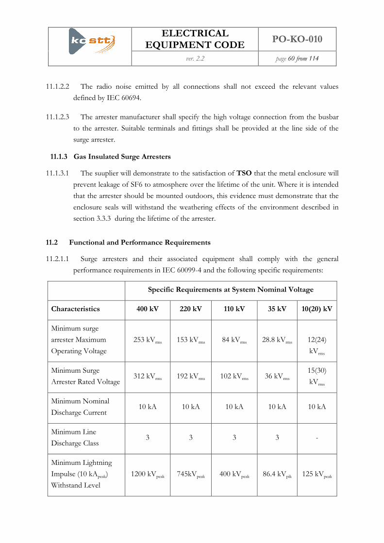
ELECTRICAL EQUIPMENT CODE
PO-KO-010
ver. 2.2 page 60 from 114
11.1.2.2 The radio noise emitted by all connections shall not exceed the relevant values
defined by IEC 60694.
11.1.2.3 The arrester manufacturer shall specify the high voltage connection from the busbar
to the arrester. Suitable terminals and fittings shall be provided at the line side of the
surge arrester.
11.1.3 Gas Insulated Surge Arresters
11.1.3.1 The suuplier will demonstrate to the satisfaction of TSO that the metal enclosure will
prevent leakage of SF6 to atmosphere over the lifetime of the unit. Where it is intended
that the arrester should be mounted outdoors, this evidence must demonstrate that the
enclosure seals will withstand the weathering effects of the environment described in
section 3.3.3 during the lifetime of the arrester.
11.2 Functional and Performance Requirements
11.2.1.1 Surge arresters and their associated equipment shall comply with the general
performance requirements in IEC 60099-4 and the following specific requirements:
Specific Requirements at System Nominal Voltage
Characteristics 400 kV 220 kV 110 kV 35 kV 10(20) kV
Minimum surge
arrester Maximum
Operating Voltage
253 kVrms 153 kVrms 84 kVrms 28.8 kVrms
12(24)
kVrms
Minimum Surge
Arrester Rated Voltage 312 kVrms 192 kVrms 102 kVrms 36 kVrms
15(30)
kVrms
Minimum Nominal
Discharge Current 10 kA 10 kA 10 kA 10 kA 10 kA
Minimum Line
Discharge Class 3 3 3 3 -
Minimum Lightning
Impulse (10 kApeak)
Withstand Level
1200 kVpeak 745kVpeak 400 kVpeak 86.4 kVpik 125 kVpeak

ELECTRICAL EQUIPMENT CODE
PO-KO-010
ver. 2.2 page 61 from 114
Specific Requirements at System Nominal Voltage
Characteristics 400 kV 220 kV 110 kV 35 kV 10(20) kV
Maximum Lightning
Impulse Residual
Voltage
769 kVpeak 447 kVpeak 225 kVpeak 94.2 kVpik 58 kVpeak
Minimum Switching
Impulse Withstand
Level
810 kVpeak 500 kVpeak 280 kVpeak 69.1 kVpik 65 kVpeak
Maximum Switching
Impulse Residual
Voltage
650 kVpeak 402 kVpeak 216 kVpeak 100.2 kVpik 42 kVpeak
Maximum Steep
Current Impulse (10
kApeak) Residual
Voltage
860 kVpeak 508 kVpeak 286 kVpeak 94.2 kVpik 65 kVpeak
Minimum Cantilever
Strength 2 kN 2 kN 2 kN 2 kN 2 kN
Maximum Radio
Interference 250 µV 200 µV 125 µV - -
11.3 Type Tests
11.3.1.1 All types of surge arrester shall be subject to type tests as specified in IEC 60099-4.
11.3.1.2 The supplier is required to demonstrate that:
(a) Satisfactory voltage grading is attained across all zinc oxide blocks.
(b) The thermal model of the arrester section used for the operating duty tests is
representative of the most highly stressed parts of the arrester.

ELECTRICAL EQUIPMENT CODE
PO-KO-010
ver. 2.2 page 62 from 114
(c) All other tests including accelerated ageing tests are carried out with the blocks
under physical conditions identical to those encountered in service.
11.3.1.3 The manufacturer shall supply details of the test method used for radio interference
and partial discharge tests. Where they have not previously been performed, the details
of the test method are to be declared prior to carrying out the type and routine test.
11.3.1.4 The supplier shall propose test methods, or submit evidence to demonstrate that the
operation counter and associated monitoring equipment (eg current indicator) can
withstand the relevant short time current and duration as specified in section 3.2.
11.4 Routine Tests
11.4.1.1 All types of surge arrester shall be subject to routine tests as specified in IEC 60099-4.
11.4.1.2 Test methods and descriptions of the routine tests showing the programme by which
electrical and mechanical characteristics of the arrester, seal integrity, shock/vibration
withstand etc, will be demonstrated following assembly, shall be declared by the
manufacturer and agreed with TSO.
11.4.1.3 Routine tests to demonstrate seal integrity and correct operation of the surge arrester
operation counter/current indicator functions are required.
11.5 Commissioning Tests
11.5.1.1 In addition to the IEC 60099-4 specification, the supplier shall specify any
commissioning tests that are recommended to ensure the satisfactory functioning of the
equipment throughout the design life.
11.5.1.2 The supplier may witness these tests and will be required to confirm that equipment
guarantees have not been invalidated.
11.6 Condition Monitoring and Maintenance
11.6.1.1 The supplier shall advise of any general maintenance procedures and monitoring
techniques that should be applied during service throughout the design life of the surge
arrester.

ELECTRICAL EQUIPMENT CODE
PO-KO-010
ver. 2.2 page 63 from 114
12 Measurement Transformers
12.1.1.1 All measurement transformers shall comply with the relevant sections of IEC 60044,
IEC 60186, the requirements of this code and, where applicable, with the requirements
of the metering code.
12.1.1.2 A single secondary terminal box shall be mounted on the measurement transformer
to accommodate the necessary secondary terminal connections, alarm equipment, links
and fuses or MCBs. Secondary terminals and connections shall be suitable for their
required purpose regarding rating, reliability and the effects of environmental conditions
and corrosion. Secondary terminal boxes shall comply with, as a minimum, the IP54
environment of IEC 60529.
12.1.1.3 Where measurement transformers are used for metering purposes, it must be possible
to for the security requirements of the metering code to be met with respect to all
terminals, links, fuses and MCBs and cabling that provide measurement quantities to
metering equipment.
12.1.1.4 For all oil filled measurement transformers the supplier shall declare the type of
insulating oil being used. For oil-filled equipment fitted with an external oil expansion
system, means shall be provided to give a permanent visual indication of the volume of
the oil. The status of the indicator should be visible from ground level.
12.1.1.5 For oil filled measurement transformers where the oil expansion system is wholly
internal (gas cushion or flexible diaphragm), the transformer shall be fitted with a
permanent internal pressure indicator. The status of the indicator shall be visible from
ground level.
12.1.1.6 All oil filled equipment shall be fitted with an oil sample valve, situated at its base,
suitable for taking oil samples for Dissolved Gas Analysis (DGA) in accordance with
IEC 567. The sample valve shall be situated on the earthed base tank of the
measurement transformer. Valves where the oil is extracted by using a hypodermic
needle are not suitable.
12.1.1.7 On all post type measurement transformers an insulation test terminal (test tap) shall
be provided for the purpose of performing capacitance and dielectric loss (tan δ)
measurements of the primary insulation during routine maintenance. The test terminals
shall be suitably identified.

ELECTRICAL EQUIPMENT CODE
PO-KO-010
ver. 2.2 page 64 from 114
12.2 Current Transformers
Secondary ratings and transformation ratios shall be selected from the following table and shall
be specified in the invitation to tender document:
Rated Voltage and
Current of
Switchgear
CT Purpose Turns Ratio Rating and Class
420kV 2500 A Line
field
Metering 1000-2000/1 15 VA Class 0.2S FS 10
Metering 1000-2000/1 15 VA Class 0.2S FS 10
Protection 1000-2000/1 20 VA 5P20
Protection 1000-2000/1 20 VA 5P20
420kV 2500 A
Connection field
Metering 1250-2500/1 15 VA Class 0.2S FS 10
Metering 1250-2500/1 15 VA Class 0.2S FS 10
Protection 1250-2500/1 20 VA 5P20
Protection 1250-2500/1 20 VA 5P20
420kV 2500 A
Transformer field
Metering 500-1000/1 15 VA Class 0.2S FS 10
Metering 500-1000/1 15 VA Class 0.2S FS 10
Protection 500-1000/1 20 VA 5P20
Protection 500-1000/1 20 VA 5P20
420kV 2500 A
Generator field
Metering 800-1600/1 15 VA Class 0.2S FS 10
Metering 800-1600/1 15 VA Class 0.2S FS 10
Protection 800-1600/1 20 VA 5P20
Protection 800-1600/1 20 VA 5P20

ELECTRICAL EQUIPMENT CODE
PO-KO-010
ver. 2.2 page 65 from 114
Rated Voltage and
Current of
Switchgear
CT Purpose Turns Ratio Rating and Class
245kV 2500 A
Connection field
Metering 1000-2000/1 15 VA Class 0.2S FS 10
Metering 1000-2000/1 15 VA Class 0.2S FS 10
Protection 1000-2000/1 20 VA 5P20
Protection 1000-2000/1 20 VA 5P20
245kV 2500 A Line
field
Metering 600-1200/1 15 VA Klasa 0.2S FS 10
Metering 600-1200/1 15 VA Klasa 0.2S FS 10
Protection 600-1200/1 20 VA 5P20
Protection 600-1200/1 20 VA 5P20
245kV 2500 A
Transformer field
Metering 600-1200/1 15 VA Class 0.2S FS 10
Metering 600-1200/1 15 VA Class 0.2S FS 10
Protection 600-1200/1 20 VA 5P20
Protection 600-1200/1 20 VA 5P20
245kV 2500 A
Generator field
Metering 400-800/1 15 VA Class 0.2S FS 10
Metering 400-800/1 15 VA Class 0.2S FS 10
Protection 400-800/1 20 VA 5P20
Protection 400-800/1 20 VA 5P20
123kV 2000 A
Transformer field (for
400/110kV
Metering 800-1600/1 15 VA Class 0.2S FS 10
Metering 800-1600/1 15 VA Class 0.2S FS 10
Protection 800-1600/1 20 VA 5P20

ELECTRICAL EQUIPMENT CODE
PO-KO-010
ver. 2.2 page 66 from 114
Rated Voltage and
Current of
Switchgear
CT Purpose Turns Ratio Rating and Class
transformation)
Protection 800-1600/1 20 VA 5P20
123kV 2000 A
Connection field (for
400/110kV
transformation)
Metering 1000-2000/1 15 VA Class 0.2S FS 10
Metering 1000-2000/1 15 VA Class 0.2S FS 10
Protection 1000-2000/1 20 VA 5P20
Protection 1000-2000/1 20 VA 5P20
123kV 2000 A
Line field (for
400/110kV
transformation)
Metering 300-600/1 15 VA Class 0.2S FS 10
Metering 300-600/1 15 VA Class 0.2S FS 10
Protection 300-600/1 20 VA 5P20
Protection 300-600/1 20 VA 5P20
123kV 2000 A
Transformer field (for
220/110kV
transformation)
Metering 500-1000/1 15 VA Class 0.2S FS 10
Metering 500-1000/1 15 VA Class 0.2S FS 10
Protection 500-1000/1 20 VA 5P20
Protection 500-1000/1 20 VA 5P20
123kV 2000 A
Connection field (for
220/110kV
transformation)
Metering 1000-2000/1 15 VA Class 0.2S FS 10
Metering 1000-2000/1 15 VA Class 0.2S FS 10
Protection 1000-2000/1 20 VA 5P20
Protection 1000-2000/1 20 VA 5P20
123kV 2000 A Metering 300-600/1 15 VA Class 0.2S FS 10

ELECTRICAL EQUIPMENT CODE
PO-KO-010
ver. 2.2 page 67 from 114
Rated Voltage and
Current of
Switchgear
CT Purpose Turns Ratio Rating and Class
Line field (for
220/110kV
transformation)
Metering 300-600/1 15 VA Class 0.2S FS 10
Protection 300-600/1 20 VA 5P20
Protection 300-600/1 20 VA 5P20
123kV 2000 A
Connection field
Metering 1000-2000/1 15 VA Class 0.2S FS 10
Metering 1000-2000/1 15 VA Class 0.2S FS 10
Protection 1000-2000/1 20 VA 5P20
Protection 1000-2000/1 20 VA 5P20
123kV 2000 A Line
field
Metering 300-600/1 15 VA Class 0.2S FS 10
Metering 300-600/1 15 VA Class 0.2S FS 10
Protection 300-600/1 20 VA 5P20
Protection 300-600/1 20 VA 5P20
123kV 2000 A
Transformer field
Metering 200-400/1 15 VA Class 0.2S FS 10
Metering 200-400/1 15 VA Class 0.2S FS 10
Protection 200-400/1 20 VA 5P20
Protection 200-400/1 20 VA 5P20
123kV 2000 A
Connection field
Metering 1000-2000/1 15 VA Class 0.2S FS 10
Metering 1000-2000/1 15 VA Class 0.2S FS 10
Protection 1000-2000/1 20 VA 5P20
Protection 1000-2000/1 20 VA 5P20

ELECTRICAL EQUIPMENT CODE
PO-KO-010
ver. 2.2 page 68 from 114
Rated Voltage and
Current of
Switchgear
CT Purpose Turns Ratio Rating and Class
123kV 2000 A linë
field (for Al-Çe
conductors with
section 240/40 mm2)
Metering 300-600/1 15 VA Class 0.2S FS 10
Metering 300-600/1 15 VA Class 0.2S FS 10
Protection 300-600/1 20 VA 5P20
Protection 300-600/1 20 VA 5P20
Metering 200/100/1 15 VA Class 0.2S FS 10
Protection 200/100/1 30 VA 5P20
Protection 200/100/1 30 VA 5P20
35 kV Transformer
field
Metering 400-800/1 15 VA Class 0.2S FS 10
Metering 400-800/1 15 VA Class 0.2S FS 10
Protection 400-800/1 15VA 5P20
Protection 400-800/1 15VA 5P20
10(20) kV
Transformer field
Metering 1250-2500/1 15 VA Class 0.2S FS 10
Metering 1250-2500/1 15 VA Class 0.2S FS 10
Protection 1250-2500/1 15VA 5P20
Protection 1250-2500/1 15VA 5P20
12.2.1.1 Primary and secondary terminal markings, and rating plate markings shall be in
accordance with IEC 60044-1 The rated continuous primary current of the current
transformer shall be chosen to exceed the maximum continuous rating of the associated
circuit and shall be selected from the standard values detailed in IEC 60044-1. A thermal
short-time current rating (Ith) shall be assigned to all current transformers in accordance

ELECTRICAL EQUIPMENT CODE
PO-KO-010
ver. 2.2 page 69 from 114
with IEC 60044-1. The value of Ith shall not be less than the corresponding value for
the associated switchgear or transformer primary plant.
12.2.1.2 Current transformer secondary terminals should allow the application of
shorting/earthing links or wiring for maintenance purposes. Separately, a terminal for
earthing purposes shall be provided within the terminal box and shall be clearly marked.
12.2.1.3 Both ends of the CT secondary windings shall be earth free.
12.2.1.4 Current Transformers for GIS Application may be mounted internally or externally to
the GIS enclosure. Adequate protection against adverse environmental conditions shall
be provided for externally mounted CTs.
12.2.1.5 Ring-Type Current Transformers supplied as loose equipment for power transformer
application shall be equipped with secondary terminals or shall be supplied with leads of
suitable length for this application. Such leads shall be capable of withstanding a power
frequency test voltage of 5 kV (peak).
12.2.1.6 Current transformers supplied with through-wall bushings can be mounted internally
or externally to the bushing. Current transformers mounted internally shall be capable
of operating within that environment. Current transformers mounted externally shall be
suitably protected against the effects of adverse environmental conditions.
12.2.1.7 Current transformers supplied as loose equipment for other switchgear applications
shall be capable of operating within that environment. Current transformers for other
switchgear applications, mounted externally, shall be suitably protected against the
effects of adverse environmental conditions.
12.2.2 Type Tests
12.2.2.1 All current transformers shall be type tested in accordance with IEC 60044-1 (type
tests) and IEC 60044-1 (special tests).
12.2.2.2 Radio interference voltage tests to IEC 60694 are to be performed on open-terminal
current transformers.
12.2.2.3 A multi chopped impulse test shall be performed on all oil filled current transformers
rated 123 kV and above.
12.2.2.4 Temperature Rise - The thermal time constant of all equipment shall be determined
on both rising and falling temperature.

ELECTRICAL EQUIPMENT CODE
PO-KO-010
ver. 2.2 page 70 from 114
12.2.2.5 For oil filled equipment oil samples for DGA shall be taken before and after the
dielectric type tests and shall comply with 12.2.4.
12.2.2.6 Accuracy at Short-Term Continuous Current Levels - Current transformers which
have a measurement specification shall have their errors determined at a current of
12000 A for 420 kV rating and 7500 A for 245 kV rating respectively. These currents
shall be withstood for a period of 3 minutes.
12.2.2.7 Routine tests shall be performed before and after all type tests.
12.2.3 Routine Tests
12.2.3.1 All current transformers shall be routine tested in accordance with IEC 60044-1
(routine tests) and (special tests).
12.2.3.2 Additional Routine Tests shall be performed in a laboratory having traceability to
National/International standards. The overall accuracy and uncertainty of the
measurement shall be demonstrated prior to testing and shall be commensurate with the
accuracy class of the transformer under test:
(a) Full accuracy routine tests to IEC 60044-1.
(b) Capacitance (Cx) and dielectric loss angle (tan δ) measurements of the primary
insulation over the voltage range 10 kV to rated voltage shall be performed.
(c) An oil sample for DGA shall be taken as described in 12.2.4 from all oil filled
CTs. The sample shall be taken at least 24 hours after the final routine electrical
testing has been performed. The results shall be included in the routine test re-
port as detailed in section 12.2.4.
12.2.4 Routine Test Reports
12.2.4.1 Routine test reports shall include details of all routine measurements made in
accordance with this specification. The information regarding the overall accuracy and
uncertainty of the accuracy measurements shall also be recorded.
12.2.4.2 During the partial discharge (PD) test, the value of measured PD at the specified test
voltage shall be recorded together with the value of the PD extinction voltage.
Extinction voltage is defined as the voltage level at which measurable PD is completely
extinguished upon decreasing test voltage. The background PD level at the time of the
test should also be recorded in the report.

ELECTRICAL EQUIPMENT CODE
PO-KO-010
ver. 2.2 page 71 from 114
12.2.4.3 Where oil samples are taken for Dissolved Gas Analysis (DGA) the report shall
contain the following information:
(a) Name and Address of the laboratory where the analysis was performed
(b) The Accuracy, Precision and Detection Limits for the individual gas
measurement expressed in either parts per million (ppm) or percentage by
volume.
(c) The Sampling Procedure (stating the Standard Method IEC 567 if applicable).
(d) The Gas Extraction Method used (stating the Standard Method IEC 567 if
applicable).
(e) Calibration Procedure adopted by the laboratory, including details of the
number of points used over the range and the gases used.
(f) Accreditation Status of the laboratory for the purposes of DGA testing.
(g) Date Sampled and Analysed.
(h) Report the following:
Measurement Units Number of Decimal Places
Oil Volume Tested ml 0
Total Gas Content % 2
Hydrogen ppm 0
Methane ppm 0
Ethane ppm 0
Ethylene ppm 0
Acetylene ppm 0
Carbon Monoxide ppm 0

ELECTRICAL EQUIPMENT CODE
PO-KO-010
ver. 2.2 page 72 from 114
Measurement Units Number of Decimal Places
Carbon Dioxide ppm 0
Oxygen ppm 0
Nitrogen ppm 0
Moisture mg/l 0
12.2.4.4 For DGA samples associated with Type Tests, the acetylene value shall be quoted to
one decimal place
12.3 Voltage Transformers
12.3.1.1 Both ends of all secondary windings shall be brought out to the terminal box to
permit connection to links, fuses or MCBs external to the transformer. Terminals that it
is intended will be earthed will be provided with links in this terminal box for this
purpose.
12.3.1.2 If required in the specification, Capacitor VTs to IEC 60186 and rated at 245kV or
420kV shall permit the use of power line carrier.
12.3.1.3 Resin Impregnated Post Type Voltage Transformers shall be provided with an
effective and supervised means for protecting the primary winding. Where fuses are
used, their condition shall be continuously monitored.
12.3.2 Performance Requirements of VTs
12.3.2.1 Voltage Transformers for protection and general use shall meet the following
requirements:

ELECTRICAL EQUIPMENT CODE
PO-KO-010
ver. 2.2 page 73 from 114
Maximal
Voltage
Rating
Accuracy
Class
Rated Burden
(VA)
Rated Voltage
Factor (pu)
Transformation
Ratio
420 0.5/3P 50 1.5, 30 Secs 400kV/√ 3: 100V/√ 3
245 0.5/3P 50 1.5, 30 Secs 220kV/√ 3: 100V/√ 3
123 0.5/3P 50 1.5, 30 Secs 110kV/√ 3: 100V/√ 3
38 0.5/3P 50 1.9, 30 Secs 35kV/√ 3: 100V/√ 3
24 0.5/3P 50 1.9, 30 Secs 20kV/√ 3: 100V/√ 3
12 0.5/3P 50 1.9, 30 Secs 10kV/√ 3: 100/√ 3
7 0.5/3P 50 1.9, 30 Secs 6.3kV/√ 3: 100V/√ 3
12.3.2.2 Metering Voltage Transformers for settlement metering purposes shall meet the
following requirements:
Voltag
e
Rating
Accuracy Class
Rated
Burden
(VA)
Rated
Voltage
Factor (pu)
Transformation Ratio
Commercial
Border
420 0.2 50 1.5, 30 Secs 400kV/√ 3: 100V/√ 3
245 0.2 50 1.5, 30 Secs 220kV/√ 3: 100V/√ 3
123 0.2 50 1.5, 30 Secs 110kV/√ 3: 100V/√ 3
38 0.2 50 1.9, 30 Secs 35kV/√ 3: 100V/√ 3
24 0.2 50 1.9, 30 Secs 20kV/√ 3: 100/√ 3
12 0.2 50 1.9, 30 Secs 10kV/√ 3: 100/√ 3
7 0.2 50 1.9, 30 Secs 6.3kV/√ 3: 100/√ 3

ELECTRICAL EQUIPMENT CODE
PO-KO-010
ver. 2.2 page 74 from 114
12.3.3 Type Tests
12.3.3.1 All oil filled voltage transformers shall be type tested in accordance with the
appropriate sections of IEC 60044 - type tests and special tests.
12.3.3.2 All capacitive voltage transformers shall be tested in accordance with IEC 60186 and
IEC 60358 as appropriate – type tests + special tests).
12.3.3.3 Radio interference voltage tests to IEC 60694 are to be performed on open-terminal
voltage transformers.
12.3.3.4 All oil filled voltage transformers rated at 123 kV and above shall be subject to a 600
chopped negative polarity impulse test at 60% of the BIL for that equipment. The time
to chop shall be between 2 and 5 µS. A full set of electrical tests shall be undertaken
before and after this test. Oil samples shall be taken for dissolved gas analysis both
before and three days after the test. This includes taking oil samples from capacitive
voltage transformers.
12.3.3.5 For the transformer to pass this test, three criteria must all be met:
(a) The results of the electrical tests before and after the impulse test must be the
same within the error specification of the test field.
(b) No degradation is found on dismantling the transformer after test
(c) Any increase in the dissolved gas analysis is within the following limits:
Dissolved Gas Allowable Increase after three days
(ppm)
Hydrogen H2 5
Methane CH4 3
Ethane C2H6 3
Ethylene C2H4 2
Acetylene C2H2 Nil
12.3.3.6 For all oil filled voltage transformers (excluding capacitive units) dissolved gas
analysis shall be undertaken before and after the specified dielectric type tests.

ELECTRICAL EQUIPMENT CODE
PO-KO-010
ver. 2.2 page 75 from 114
12.3.3.7 Routine tests shall be performed before and after all type tests.
12.3.4 Routine Tests
12.3.4.1 All voltage transformers shall be routine tested in accordance with IEC 60044
(routine tests) and (special tests).
12.3.4.2 Routine Accuracy Tests shall be performed in a laboratory having traceability to
National/International standards. The overall accuracy and uncertainty of the
measurement shall be demonstrated prior to testing and shall be commensurate with the
accuracy class of the transformer under test.
a) Full accuracy routine tests to IEC 60044-2.
b) Capacitance Cx and dielectric loss angle (tan δ) measurements of the primary in-
sulation over the voltage range 10 kV to rated voltage shall be performed.
c) In the case of inductive VTs, an oil sample for DGA shall be taken as described
in 12.3.5 from all oil filled VTs. The sample shall be taken at least 24 hours after
the final routine electrical testing has been performed. The results shall be in-
cluded in the routine test report as detailed in section 12.3.5.
12.3.5 Routine Test Reports
12.3.5.1 Routine test reports shall include details of all routine measurements made in
accordance with this specification. The information regarding the overall accuracy and
uncertainty of the accuracy measurements shall also be recorded.
12.3.5.2 During the partial discharge (PD) test, the value of measured PD at the specified test
voltage shall be recorded together with the value of the PD extinction voltage.
Extinction voltage is defined as the voltage level at which measurable PD is completely
extinguished upon decreasing test voltage. The background PD level at the time of the
test should also be recorded in the report.
12.3.5.3 Where oil samples are taken for Dissolved Gas Analysis (DGA) the report shall
contain the following information:
a) Name and Address of the laboratory where the analysis was performed
b) The Accuracy, Precision and Detection Limits for the individual gas
measurement expressed in either parts per million (ppm) or percentage by
volume.
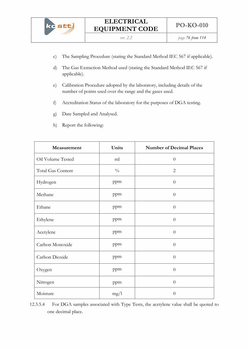
ELECTRICAL EQUIPMENT CODE
PO-KO-010
ver. 2.2 page 76 from 114
c) The Sampling Procedure (stating the Standard Method IEC 567 if applicable).
d) The Gas Extraction Method used (stating the Standard Method IEC 567 if
applicable).
e) Calibration Procedure adopted by the laboratory, including details of the
number of points used over the range and the gases used.
f) Accreditation Status of the laboratory for the purposes of DGA testing.
g) Date Sampled and Analysed.
h) Report the following:
Measurement Units Number of Decimal Places
Oil Volume Tested ml 0
Total Gas Content % 2
Hydrogen ppm 0
Methane ppm 0
Ethane ppm 0
Ethylene ppm 0
Acetylene ppm 0
Carbon Monoxide ppm 0
Carbon Dioxide ppm 0
Oxygen ppm 0
Nitrogen ppm 0
Moisture mg/l 0
12.3.5.4 For DGA samples associated with Type Tests, the acetylene value shall be quoted to
one decimal place.

ELECTRICAL EQUIPMENT CODE
PO-KO-010
ver. 2.2 page 77 from 114
13 Earthing
13.1.1.1 The requirements of this section shall apply to new substations, cable sealing end and
tower constructions and where reasonably practicable to extensions or modifications of
existing substations and cable sealing ends and tower refurbishment.
13.1.1.2 All earthing systems shall be designed and installed to comply with all relevant laws
and regulations.
13.1.1.3 Where a substation, cable sealing end or tower is being extended or modified, TSO
will determine whether it is necessary to control the rise of earth potential in accordance
with section 13.1.2. If not stated, this requirement need not be applied.
13.1.2 Rise of Earth Potential
13.1.2.1 The safety of all persons on, or in the vicinity of, high voltage sites, and persons who
may contact any conducting services to, or passing through high voltage sites, is
dependent on the design of the earthing system and its associated electrical isolation.
The design of the earthing system at substations shall limit the step and touch potentials
to safe levels given in the following table:
Maximum Voltage for
Touch
Maximum Voltage for
Step
Chippings surface (150
mm)
1.4kV 4.6kV
Soil Surface 1.0kV 3.1kV
The limits in this table assume a 200 ms clearance time, a 1 m step distance and a footwear
resistance of 2 kΩ per shoe. They are based on curve c1 of Figure 14 of IEC 479-1.
13.1.2.2 In the event that an insulating coating is required to be applied to the tower legs to
manage the risks associated with touch potentials, then the coating specification shall
comply with the following minimum requirements:
(a) Minimum Rated voltage withstand: 50kV
(b) Coverage: From ground level to 2.5m above ground level
(c) Minimum Service Life: 10 years

ELECTRICAL EQUIPMENT CODE
PO-KO-010
ver. 2.2 page 78 from 114
(d) The coating shall not serve to aid climbing of the tower
(e) The coating shall not prevent the fitting of step bolts
(f) The coating shall be resistant to minor impact damage
(g) The coating shall be dark or light grey and shall generally be unobtrusive
13.1.2.3 Cable sealing ends shall be treated as substations unless otherwise determined by
TSO.
13.1.2.4 Third party rise of earth potential impact voltage thresholds via proximity
(conduction via the ground) effects are given in the following table:
Type of Third Party Property Threshold Limit Voltage
Households and commercial property 1700V
Large hazardous process plants 650V
Railways and other traction systems 1150V
13.1.2.5 Where a TSO substation provides a connection to a system user, the applicable
threshold limit values via conduction (via metallic earth conductors) are given in the
following table:
Type of Third Party Property Threshold Limit Voltage
Households and commercial property Not applicable
Large hazardous process plants 650V
Railways and other traction systems 430V
13.1.2.6 The design of the earth electrode system (whether this is as a result of adding to an
existing system or the installation of new system), shall be optimised in so far as is
reasonably practical to ensure third party impact threshold voltages are within the limits
in the tables in sections 13.1.2.4 and 13.1.2.5. In particular, consideration shall be given
to the arrangement of the electrode system and the use of all land within the substation

ELECTRICAL EQUIPMENT CODE
PO-KO-010
ver. 2.2 page 79 from 114
boundary. It is only necessary to use land outside the substation boundary that is within
TSO’s ownership or control if stated by TSO. The earth electrode depth and geometry
shall be optimised to make use, as far as practicable, of lower resistivity ground strata.
13.1.2.7 Where reasonably practicable, the earthing system shall be designed using an earth
return current which is 20% greater than that calculated, to allow for future increases in
system fault current.
13.1.2.8 Communication cables connecting to all TSO substations must be fitted with
appropriate electrical isolation.
13.1.3 Earth Electrodes
13.1.3.1 Earth electrodes shall be designed to operate satisfactorily during faults, taking into
account the area of the electrodes in contact with earth, the soil resistivity and earth
electrode current magnitude and duration, in accordance with DIN 46011. The fault
duration times to be used for rating the electrodes are 1 second for 220 kV and 400 kV
and 3 seconds for all other nominal system voltages.
13.1.3.2 Buried bare copper horizontal earth electrodes shall be installed at around 500 mm
depth. If the indigenous soil is hostile to copper (corrosive soils containing acids,
nitrates, sulphides, sodium silicates, ammonium chlorides or sulphur dioxides that may
have a significant effect on the earthing system over a design life of not less than 40
years), the electrode shall be surrounded by 150 mm of non-corrosive soil of fine
texture, firmly rammed. Where there is a likelihood of soil migration and leaching,
alternative materials may be used.
13.1.3.3 Conductors installed in ploughed farmland shall be buried at least 1 m deep, at all
points, measured from undisturbed ground level. Where horizontal earthing conductors
are exposed to indigenous soils that are hostile to copper, stranded copper conductors
are not permitted within the earthing design.
13.1.3.4 Driven rod electrodes shall be used to exploit lower resistivity ground strata where
present to reduce the site rise of earth potential in accordance with section 13.1.2.
Where the ground is hard and rods cannot be driven, consideration shall be given to
drilling holes to install the rods and back filling with a suitable low resistance fill
material.

ELECTRICAL EQUIPMENT CODE
PO-KO-010
ver. 2.2 page 80 from 114
13.1.3.5 Buried conductors and electrodes shall be at least 3 m away from buried cables with
uncovered metallic sheaths, unless the sheaths are used as part of the earthing system.
13.1.3.6 Where beneficial, reinforcing steelwork incorporated within piling shall be utilised as
an earth electrode. However, care must be taken to ensure that the current carrying
capacity of the steelwork is not exceeded. Connections shall be made to each vertical
steel bar within the pile cap. Connections brought out through the pile cap shall be
provided with appropriate means to prevent moisture ingress into the cap.
13.1.3.7 Fortuitous connections or temporary must not be relied upon.
13.1.3.8 Where sheet steel piles of the interlocking kind are used as an earth electrode,
connections shall be made to each pile.
13.1.3.9 Where there is more than one TSO controlled substation on the same site a separate
earth grid shall enclose each substation and these grids shall be connected together at
the extremities by at least two fully rated conductors ideally taking secure separate
physical routes. In order to facilitate testing of the interconnections, the conductors
connecting the systems together shall each be made accessible at a designated point. At
this point the conductors shall have dimensions which would fit inside a 25 mm
diameter circular clamp meter jaws (min length of conductor 75 mm).
13.1.3.10 Where a TSO substation is located on the same site as a system user’s substation,
the earthing systems shall be interconnected. Measures shall be taken to ensure that
persons can not come into contact with hazardous transferred potentials between
substations or directly connected customers, particularly where sites are separated.
Where control of these potentials requires measures to be taken by a system user or
other third party, TSO shall be informed by the supplier at the time of production of
the earthing design.
13.1.3.11 Disconnectable test links must not be fitted where HV earthing systems are
connected together.
13.1.4 Earth Electrode Arrangement
13.1.4.1 Unless otherwise agreed, the earthing electrode arrangement shall be based on a
peripheral buried main bare earthing conductor generally encompassing the plant items
to be earthed, with buried spur connections, from the main conductor to the items of
plant. The main earthing conductor shall be augmented with inter-connected buried
bare cross connections to form a grid. In addition, where beneficial, groups of earth

ELECTRICAL EQUIPMENT CODE
PO-KO-010
ver. 2.2 page 81 from 114
rods distributed around the periphery shall be connected to this main earthing
conductor.
13.1.4.2 For indoor substations the earthing grid shall be installed with spur connections to
the steel reinforcing mat of the concrete floor, every 20 m. Additionally, a second
peripheral main earthing conductor shall be buried at 1 m distance from the building,
which shall be bonded to the first main conductor, and to the building if it is metal clad,
both at 20 m intervals. Earth rod groups shall be connected to the second peripheral
conductor as previously described.
13.1.5 Test Facilities
13.1.5.1 To allow testing of all earth electrode groups, a section of conductor connecting to
each group shall be made accessible and shall have dimensions that would fit inside 25
mm diameter circular clamp meter jaws (min length 75 mm). This section of conductor
shall be a part of a spur connection to the rod group so that all the test current flows
into the rod group and is not diverted into the main earth system.
13.1.5.2 Disconnectable links must not be fitted in the connections from the main earth
system to terminal towers or rod groups or in the connections between main earth
systems, on sites where more than one main earth system exists.
13.1.6 Equipment Connected to the Main earth system
13.1.6.1 The following items of equipment shall be connected to the main earth system by a
fully rated conductor:
(a) All points which may form the earth of a high voltage fault path.
(b) Transformer winding neutrals required for HV system earthing. Earthing
connections for MV system may be via earthing resistors or other current
limiting devices.
Arrangement of neuter made as in the following table:
Voltage Treatment of neuter
10 kV Isolated neuter or connected through resistor of 20 Ω or 40 Ω for limited one-phase current through earthing up to 150 A - 300 A..
20 kV Earthing through a resistor of 20 Ω which limits current through earthing up to 300 A

ELECTRICAL EQUIPMENT CODE
PO-KO-010
ver. 2.2 page 82 from 114
35 kV Earthing through an inductive resistor (Petersen coil) which limits current through earthing up to 300 A
(c) In the case of a manually operated earthing or MV switch, a dedicated fully rated
conductor shall be run from the handle or mechanism box to the main earth
system as directly as possible and this conductor shall pass under the stance
position of the person operating the switch. The conductor runs to any fault
points associated with the switch shall, where practicable, be maintained separate
from the handle or mechanism of the switch and connecting metalwork.
13.1.6.2 Where appropriate in the design of the substation, one point of a delta connected
tertiary winding that is not providing load shall be connected to the main earth system
by a fully rated conductor.
13.1.6.3 All metalwork e.g. panels, cubicles, kiosks etc, including the steelwork of buildings,
shall be bonded to the main earth system by a conductor of no less than 70 mm2 cross
section. Strip conductor shall be no less than 3 mm thick.
13.1.6.4 Mechanical linkages, e.g. turnbuckles, shackles etc, which could form part of the earth
connection shall be shunted across using fully rated flexible conductor to prevent
damage by the passage of fault current.
13.1.6.5 Metallic trench covers shall be earthed to cater for the possibility of an earth fault on
cabling in the trench and to cater for the possibility of induced or transferred potentials.
To achieve this, metal trench covers may be laid on conducting support(s) that shall
each be connected to the main earth system by a conductor as specified above.
13.1.7 Installation
13.1.7.1 Earth conductors in trenches containing power and/or multicore cables shall be fixed
to the walls approximately 100 mm from the top to maintain separation from the cables.
13.1.7.2 Due regard shall be given to the possibility of mechanical damage to buried
conductors and, where necessary, either marker tapes and/or mechanical protection
shall be installed. A separation of at least 500 mm to civil works such as drainage pits
shall be maintained.
13.1.7.3 Conductor runs above ground shall be designed to minimise the possibility of
mechanical damage.

ELECTRICAL EQUIPMENT CODE
PO-KO-010
ver. 2.2 page 83 from 114
13.1.7.4 When laying stranded conductors, care shall be taken to avoid distorting individual
strands.
13.1.7.5 Conductors shall be fixed firmly and tidily to structures at a spacing of no more than
1 m. The fixings shall not allow galvanic corrosion to occur and shall not require the
conductor to be drilled unless otherwise agreed.
13.1.7.6 Where earth conductors cross they shall be jointed (other than in the case of rod
groups where these must be maintained separate to permit testing).
13.1.7.7 Where earth conductors connect to equipment the connections shall as far as
practicable be made onto vertical surfaces only. Connections to the metal cladding of
buildings shall be inside the building.
13.1.7.8 Aluminium conductor shall only be installed at least 250 mm above ground level. All
conductor joints shall be in accordance with section 4.26.
13.1.7.9 Where specified, buried earth tape shall be protected from theft by measures such as
concrete anchors or securing to driven earth rods.
13.1.7.10 Bolted joints are not acceptable below ground other than for earth rod screw
couplings which shall be thoroughly greased. Connections to buried earth rods shall be
welded in accordance with section 4.26.
13.1.8 Portable Earthing
13.1.8.1 Loops for portable earths shall be provided on the earthing conductor at each
location where portable earths may be required to be applied. The loops shall be fully
rated and suitable for TSO standard portable earthing equipment, and shall be made of
copper or aluminium. The loops shall be not less than 230 mm long and shall be 75 mm
clear of the earthing conductor. Loops for portable earths shall be installed at a
convenient height and shall be separately formed, i.e. not by bending the earthing
conductor.
13.1.8.2 The rating of multiple portable earth leads shall be as listed in the following table:

ELECTRICAL EQUIPMENT CODE
PO-KO-010
ver. 2.2 page 84 from 114
Number of leads (150 mm2
aluminium)
Rating
1 17.5kA
2 31.5kA
3 47.25kA
4 63kA
13.1.9 Steel Support Structures
13.1.9.1 Where the current carrying capacity of steel support structures is at least equal to the
switchgear rating, it is preferred that the structure is utilised to form part of the
connection to the main earthing system, in which case there is no need to fix an earth
conductor along this section.
13.1.9.2 Where a steel structure is relied upon to provide an earth connection for supported
equipment, current carrying joints within 2.4 m of ground level shall be in accordance
with section 4.26. Above 2.4 m the normal structural joints are considered adequate for
electrical integrity during fault conditions.
13.1.9.3 Steel structures shall not be relied upon to conduct high frequency currents or for
earth connections to earth switches.
13.1.9.4 Where post insulators, other than those forming part of shunt connected equipment
(e.g. CTs, VTs, surge arrestors) are supported by a steel structure the insulator base does
not require a bridging connection to the structure.
13.1.10 Fences
13.1.10.1 Measures shall be taken to ensure that dangerous touch or transferred potentials
cannot arise on substation fences. Perimeter fences may be independently earthed using
5 m long rod electrodes or may be connected to the main earth system.
13.1.10.2 Where a perimeter fence is independently earthed, 2m separation must be maintained
between the fence and the main earth system and equipment connected to it.

ELECTRICAL EQUIPMENT CODE
PO-KO-010
ver. 2.2 page 85 from 114
13.1.10.3 Unless otherwise agreed, where a perimeter fence is connected to the main earth
system an additional buried bare conductor shall be installed 1 m outside the fence
buried at a depth of 0.5 m to control touch potentials. This conductor shall be
connected to the main earth system and fence at 50 m min intervals.
13.1.10.4 Internal fences within the curtilage of the main earth system shall be connected to it
at 50 m min intervals and at changes of direction and where power lines cross overhead.
Unless otherwise agreed, internal fences not within the curtilage of the main earth
system shall have an additional buried bare conductor installed 1 m on either side of the
fence buried at a depth of 0.5 m connected to the fence at 50 m intervals to control
touch potentials.
13.1.10.5 Where a fence, which is connected to the main earth system, abuts an independently
earthed fence they shall be electrically separated using either a non-metallic fence panel
or an insulating section having 5 cm (approximately) creep age at each end of a 2 m
section which is not connected electrically to either of the fences.
13.1.10.6 A cable having a metallic covering effectively in contact with the ground or a bare
conductor which passes underneath an independently earthed fence shall be covered
with insulation for a distance of 2 m on either side of the fence. For example this may
be achieved by running the conductor in a tube pipe of 2 m on each side of the fence.
13.1.10.7 Where galvanised steel chain link internal fencing is used, a separate earth conductor
shall be installed along the fence (min 70 mm2) and shall be connected to each section
of fence every 10 m or less and to the main earth system at 50 m intervals.
13.1.10.8 Where plastic coated steel chain link internal fencing is used, connection to the main
earthing system shall be made at all fence guide wire anchor points (min 70 mm2).
Connections to the fence shall be via a conductor which shall be accessible and shall
have dimensions which would fit inside 25 mm diameter circular clamp meter jaws.
Where bolted joints are used to connect to the fence, these shall be protected with
Denso Mastic and Tape or outdoor grade silicon sealer.
13.1.11 Access/Egress Gates
13.1.11.1 Access/egress gates are not required to be bonded to its supporting post. This should
not be confused with the requirement to cross bond between gate supporting posts.
This requirement should still be met.
ELECTRICAL EQUIPMENT CODE
PO-KO-010
ver. 2.2 page 86 from 114
13.1.12 Temporary Fences
13.1.12.1 Temporary metallic fences shall be installed with appropriate measures to limit touch
or transferred potentials to safe levels.
13.1.12.2 An internal metallic fence within the curtilage of the main earth system shall be
connected to the main earth system at 50 m intervals, at changes of direction and where
power lines cross overhead.
13.1.12.3 Where a temporary metallic fence which is connected to the main earth system abuts
an independently earthed fence they shall be electrically.
13.1.12.4 A fence outside the curtilage of the main earth system may present a greater hazard
where it crosses the ground voltage profile. In this case, in order to limit the transferred
potential, the fence shall either be non-metallic or shall have its sections electrically
insulated from each other at intervals depending on the ground voltage profile at the
site.
13.1.13 Terminal Towers
13.1.13.1 Where the earth wire of an incoming line terminates on a tower it shall be connected
to the top of the tower. The tower shall be connected to the adjacent substations main
earth system (not rod groups) at two separate points by two spur copper tape
conductors following secure separate routes. The copper tape shall have a cross section
no less than 50 mm x 6 mm. There shall be no disconnectable links in these
connections. These conductors shall be connected to different legs of the tower and
shall be adequately protected to prevent damage and deter theft. Where these
conductors cross or come close to rod groups they shall be insulated to maintain an
electrical separation between bare conductors of 2 m minimum.
13.1.13.2 Where a terminal tower leg is within 2 m of an independently earthed fence, the
affected sections of fence shall be connected to the tower and insulated sections fitted
either side of the affected sections.
13.1.14 Gas Insulated Substations
13.1.14.1 Gas insulated substations with single phase enclosures have specific earthing
requirements to reduce circulating currents in supporting steelwork.
13.1.14.2 The main earth system shall be well integrated in the regions close to equipment with
short spur connections taken to specific points. Connections to this system, together

ELECTRICAL EQUIPMENT CODE
PO-KO-010
ver. 2.2 page 87 from 114
with direct connections between phases shall be made at all line, cable and transformer
terminations, at busbar terminations and at approximately 20 m intervals in busbar runs.
Inter-phase connections shall be rated to carry induced currents resulting from the flow
of rated normal current in the primary conductors.
13.1.15 Anti-climbing Precautions along the Tops of Walls
13.1.15.1 Where barbed wire or other metal anti-climbing devices are erected along the tops of
brick walls etc these shall be connected to earth using the same procedure as with
fencing.
13.1.16 Design Life of Installation
13.1.16.1 All parts of the earthing installation, both below and above ground, shall have a
design life of 40 years taking into account the anticipated corrosion of the conductors
resulting from site chemical pollution.
13.2 Test Requirements
13.2.1.1 Validation by electrical measurement of any design is required for all installed systems
to confirm the satisfactory installation and design of the system. TSO reserves the right
to witness all tests.
13.2.1.2 The resistance to earth of all individual rods and rod groups shall be measured and
recorded. Where the measured resistance of an individual rod is more than 50% higher
than the average for the site the reason shall be investigated and the rod(s) re-installed if
necessary.
13.2.1.3 The total substation earth electrode impedance shall be measured using the AC Fall
of Potential Method and the result recorded. The measured result shall be compared
with that predicted by calculation and any significant difference investigated.
13.2.1.4 Tests of all electrical joints shall be made in accordance with section 4.26.2.
14 Auxiliary Supplies
14.1.1.1 This section defines the technical requirements for the application of substation
auxiliary equipment and describes the functional and performance requirements for
both AC and DC auxiliary power supplies for equipment in substations. The
operational security of substations and the availability of the high voltage plant and

ELECTRICAL EQUIPMENT CODE
PO-KO-010
ver. 2.2 page 88 from 114
secondary equipment within the substation is dependent upon reliable and secure
auxiliary supplies.
14.1.1.2 Manufacturing facilities for equipment forming part of an auxiliary supply installation
shall be certified by a recognised accreditation organisation to ISO 9001. Manufacturers
shall preferably have in place or be working towards installation of management systems
compatible with the environmental management system standard ISO 14001.
14.1.1.3 No-break supplies for protection, control, measurements, telecommunications and
other electronic equipment shall normally be fed from 48 V (DC) and/or 110 V (DC)
supplies. The preferred choice of supply for light current equipment is 110 V (DC).
14.1.1.4 Alternating current supplies may be used where a short duration supply interruption
is tolerable (typically 0-2 min arising from the time taken for a supply to change over or
for diesel standby generation to run up to speed). Where a break is not acceptable and
the equipment requires a no-break AC supply such as for a computer and monitor then
it shall be fed from a DC supplied inverter or a stand-alone uninterruptible power
supply (UPS).
14.1.1.5 For safety reasons, the use of 230 V (AC) supplies for control systems should be
avoided where reasonably practicable. If AC supplies must be used for general control
purposes, a suitable transformer providing 110 V with centre tapped earth is
recommended to derive an acceptable control voltage.
14.1.1.6 The LVAC power supply shall be designed to provide a voltage maintained within the
limits of 400/230 V + 10%, - 6% and 50 Hz ± 1%.
14.1.1.7 All components of the LVAC supply should be capable of operating correctly at the
levels of harmonics specified in IEC 50160.
14.1.1.8 48 V and 110 V (DC) supply systems at 400 kV and 220 kV substations shall be
provided by two independent DC supply systems.
14.1.1.9 Interconnection facilities between the independent dc supply systems for each voltage
level shall be provided at each substation. Common mode faults shall be minimised
wherever possible.
14.1.1.10 Cross connections of DC supply systems between adjacent dispersed relay rooms,
where the relay rooms belong to primary 400/220 kV circuits carried on the same route,
shall be arranged to avoid common mode faults.

ELECTRICAL EQUIPMENT CODE
PO-KO-010
ver. 2.2 page 89 from 114
14.1.1.11 Each independent system shall be designed for a six hour standby period with the
maximum load of the associated distribution board.
14.1.1.12 In double owned substations e.g. SS 110/35 kV and 110/10(20) kV, self supplied will
be realised as autonom toward separated equipments (plants). Responsibility for their
maintaining and operation also will be divided.
14.1.1.13 In the Connection Code in details will be specified the responsibilities of the TSO
and connectees in case of self supplied as above paragraph.
14.2 Performance Requirements
14.2.1 Alternating Current Supplies
14.2.1.1 All equipment supplied shall be provided with the following degrees of protection
against ingress of objects and moisture, as specified in IEC 60529.
14.2.1.2 In the case or outdoor equipment, the level of protection during normal operation
shall be IP54. With access doors open, without the use of tools, the level of protection
of live electrical conductors shall be IP20.
14.2.1.3 In the case of indoor equipment, the level of protection during normal operation shall
be IP31. With access doors open, without the use of tools, for the level of protection of
live electrical conductors shall be IP20.
14.2.2 Direct Current Supplies
14.2.2.1 Direct current systems shall provide no-break supplies at all times up to the end of
the specified standby period.
14.2.2.2 The power supply systems and cabling shall be sized to ensure that the battery is
capable of supplying the load requirements at the end of the 6 hour standby period. At
the end of the 6-hour standby period the voltage measured at the distribution board,
with an ambient temperature of 5ºC, shall not be less than 46 V in the case of 48 V
nominal systems, 102 V in the case of centralised 110 V systems and 93 V for dispersed
110 V systems.
14.2.2.3 The 110 V batteries shall be capable of supplying the maximum tripping load at the
end of the 6 hour standby period. This is defined as the tripping of all the required plant
associated with that battery for a primary busbar fault.

ELECTRICAL EQUIPMENT CODE
PO-KO-010
ver. 2.2 page 90 from 114
14.2.2.4 The battery/charger system shall at all times maintain the voltage at the distribution
board(s) within the following levels (taking into account the permissible variance in
alternating current supply voltage at the charger):
Normal Maximum Centralised
Systems
Minimum
Dispersed
Systems
Minimum
Voltage Range
for 110 V
nominal systems
125 137.5 102 93
Voltage Range
for 48 V nominal
systems
54 60 46 ----
15 Protection and Protection Grading
15.1.1.1 This section defines protection grading arrangements at interfaces between TSO and
system users to ensure that adequate discrimination of protection is achieved and the
arrangements that apply to shared protection equipment. It sets out the protection
setting requirements that, when applied, will ensure compliance with the Grid Code
with respect to protection discrimination. It also establishes principles applicable to
protection in boundary substations to ensure the security of the transmission system
is not jeopardised by non-clearance of faults on system user’s networks.
15.1.1.2 Protection setting, and other information, that is to be used for the purpose of
protection grading shall be exchanged between TSO and the system user as required to
ensure the secure and reliable operation of the combined networks. If the system user
believes that the required grading stated in this section cannot be achieved TSO must
be consulted.

ELECTRICAL EQUIPMENT CODE
PO-KO-010
ver. 2.2 page 91 from 114
15.2 Protection Principles
15.2.1 Use of Differential Protection on Short Feeders
15.2.1.1 Differential protection will normally be installed on overhead circuits. Where circuits
are mainly comprised of underground cable or where circuits are less than 5 km in
length, a differential protection system shall be employed. Where two main protection
schemes are employed, they shall be of different manufacture and, where possible, shall
use different design components.
15.2.1.2 In the case of short circuits entirely comprised of overhead line then, where two main
protection schemes are installed and subject to the agreement of TSO, one main
protection scheme shall be a differential scheme and the other shall be a distance
protection scheme.
15.2.2 Supervision of Circuit Breaker Main Contacts and Trip Circuits
15.2.2.1 Equipment shall be provided on all three phase circuit breakers where the operating
contacts of all phases are not mechanically interconnected to detect that the main
contacts of all phases are in the same position (either all open or all closed). Where the
contacts of all phases are not in the same position, and this situation continues for:
a) longer than 2 seconds in the case of circuit breakers where single phase auto
reclose is fitted, or
b) longer than 500mS in all other cases,
Then a trip signal shall be sent to all phases of the circuit breaker.
15.2.2.2 Two separate trip circuits, with separate trip coils, shall be provided on all circuit
breakers connected to the transmission network. All trip circuits shall be fitted with
trip circuit supervision facilities providing local and remote alarms. It shall be possible to
isolate the remote alarm facility when circuit breakers are removed from service for
maintenance purposes. The design of the isolation scheme should ensure that remote
supervision is restored when the circuit breaker is returned to service.
15.2.3 Fault location facilities on long overhead line circuits
15.2.3.1 In the case of all overhead lines over 30 km, fault locators shall be installed.

ELECTRICAL EQUIPMENT CODE
PO-KO-010
ver. 2.2 page 92 from 114
15.2.4 Power System Instability and Under Frequency
15.2.4.1 To guard against power system oscillations causing instability in the regional power
system, protection systems shall be installed on all 400kV circuits to detect power
swings and to trip the circuit breaker where power flow oscillations continue for a
period of 3 S.
15.2.4.2 All system users whose networks may supply a net demand of more than 20 MW
shall install under-frequency protection to trip the incoming circuit breakers in the event
that system frequency falls.
15.2.4.3 The setting of all under frequency relays shall be under the control of TSO and it
shall be possible for TSO to apply security seals to ensure that settings are not altered
without the direct involvement of TSO.
15.2.4.4 Where the network of a system user supports a key public service, then the system
user may also provide under-frequency protection on all circuits from the same
incoming switchboard and seek that higher settings are applied to this protection than
are applied to the incoming circuits.
15.2.5 400 kV Network
15.2.5.1 At all points of the 400kV network, two totally separate main protection schemes
shall be installed, operating separate trip coils on the appropriate circuit breakers. On
overhead circuits greater than 5 km in length, these two protection schemes shall both
be distance protection systems but of different manufacture and, where possible, use
different design components.
15.2.5.2 Distance protection shall be set such that zone 1 shall be 80% of the line length and
shall initiate a trip signal within 40mS; zone 2 shall extend to 50% of the shortest
subsequent circuit and shall initiate a trip signal after a fault duration of 250mS; zone 3
shall extend to 120% of the longest subsequent circuit and shall initiate a trip signal after
a fault duration of 500mS and zone 4 shall be a reverse direction zone initiating a trip
signal after a fault duration of 750 ms.
15.2.5.3 To ensure high resistance earth faults at the remote end of a circuit are cleared,
distance protection schemes shall incorporate directional earth fault protection
connected in the CT residual circuit. This shall be set such that a trip signal is
immediately initiated if an earth fault current of 50% of the normal line current is
detected.

ELECTRICAL EQUIPMENT CODE
PO-KO-010
ver. 2.2 page 93 from 114
15.2.5.4 In compliance with the requirements of the Grid Code, a two stage overcurrent (as
thermal overload) protection will be installed on all circuits and single phase high speed
auto-reclose facilities shall be provided on all overhead line circuits.
15.2.6 220 kV Network
15.2.6.1 At all points of the 220kV network, two totally separate main protection schemes
shall be installed, operating separate trip coils on the appropriate circuit breakers. On
overhead circuits greater than 5 km in length, these two protection schemes shall both
be distance protection systems but of different manufacture and, where possible, use
different design components.
15.2.6.2 Distance protection shall be set such that zone 1 shall be 80% of the line length and
shall initiate a trip signal within 50mS; zone 2 shall extend to 50% of the shortest
subsequent circuit and shall initiate a trip signal after a fault duration of 400 mS; zone 3
shall extend to 120% of the longest subsequent circuit and shall initiate a trip signal after
a fault duration of 800 mS and zone 4 shall be a reverse direction zone initiating a trip
signal after a fault duration of 1200 ms.
15.2.6.3 In compliance with the requirements of the Grid Code, a two stage overcurrent (as
thermal overload) protection will be installed on all circuits and auto-reclose facilities
shall be provided on all overhead line circuits. The auto-reclose equipment may permit
either single phase or three phase reclosure depending on the fault tripping
arrangements.
15.2.6.4 Three phase auto-reclose equipment shall permit reclosure onto an overhead line that
has tripped on transient fault either where the circuit has been confirmed to be de-
energised or where the voltages on both sides of the circuit breaker have been proved to
be in synchronism within established limits.
15.2.7 110 kV Network
15.2.7.1 On 110 kV circuits, one main protection system plus a two stage overcurrent (as
thermal overload) protection scheme shall be installed and shall operate separate circuit
breaker trip coils. Where the main protection continues to detect the passage of fault
current and this is confirmed by the detection circuits of the two stage overcurrent
protection, a trip signal shall be sent without delay to the trip coils operated be the
overcurrent protection.

ELECTRICAL EQUIPMENT CODE
PO-KO-010
ver. 2.2 page 94 from 114
15.2.8 Breaker Fail Protection
15.2.8.1 Where a fault continues for 150mS after a trip signal has been initiated, breaker fail
protection shall operate so that the circuit breakers on all infeeds to the affected busbar
zone trip. The continuing fault condition shall be proved by more than one protection
system. In the case of 220 kV and 110 kV circuits where only 1 main protection scheme
is fitted, this may be a combination of main and back-up protection where the time
setting of the back-up overcurrent protection is set to zero on operation of the main
protection.
15.3 Use of shared Current Transformers
15.3.1.1 Current transformers as described in section 12.2 shall be installed at the network
boundaries. One of the two protection cores may be used by the system user for their
main protection and the other core will be used by TSO for busbar protection
purposes. With the consent of TSO to the burden to be applied, the system user may
connect overcurrent protection on the busbar protection.
15.3.1.2 Before any tests that involve primary injection of shared current transformers are
carried out by the system user, the approval of TSO to the proposed test schedule
shall be obtained.
15.4 Transformer Protection
15.4.1.1 Transformers connected to the network of the TSO shall have the following
protection:
(a) Overall Differential Protection
(b) Restricted Earth Fault Protection
(c) Bucholtz Protection – Alarm and Trip
(d) Winding Temperature – Alarm and Trip
(e) Overcurrent Protection on HV and LV sides
(f) Earth Fault Protection on LV side
(g) Earth Fault Protection on Transformer Neutral Connections

ELECTRICAL EQUIPMENT CODE
PO-KO-010
ver. 2.2 page 95 from 114
(h) Tank Earth Protection
15.4.1.2 In the case of transformers having tertiary windings, overcurrent and earth fault
protection shall also be applied to the tertiary winding.
15.5 Overcurrent Protection on Networks of System Users
15.5.1.1 Overcurrent protection shall be set to provide both current and time grading with
two stage overcurrent protection installed on the TSO network. The settings applied to
overcurrent protection on the TSO network shall be:
Conductor Winter Summer
Stage 1 Stage 2 Stage 1 Stage 2
Al/Fe 150/25 mm2 620 A 740 A 350 A 510 A
Al/Fe 240/40 mm2 840 A 1010 A 480 A 710 A
Al/Fe 360/57 mm2 1080 A 1310 A 610 A 910 A
Al/Fe 490/65 mm2 1290 A 1570 A 710 A 1090 A
Al/Fe 490/65 mm2*2 2580 A 3140 A 1420 A 2180 A
Cu 150 mm2 700 A 850 A 280 A 550 A
TACSR 150 mm2 620 A 740 A 350 A 510 A
Cu 95 mm2 510 A 640 A 220 A 420 A
The time settings that are applied shall be:
Alarm Trip
Stage 1 20 Seconds 20 Minutes
Stage 2 – Overhead Lines 20 Seconds
Stage 2 – Underground Cable 3 Seconds
ELECTRICAL EQUIPMENT CODE
PO-KO-010
ver. 2.2 page 96 from 114
15.5.1.2 Current grading shall be achieved to ensure that the current setting deployed on the
system user’s plant (e.g. outgoing feeder, transformer, reactor) protection is smaller
than the setting used on TSO’s overcurrent protection. In cases where overcurrent
protection is installed on both sides of a TSO owned transformer, the system user’s
current setting shall be smaller than the lower of the HV and LV transformer
overcurrent protection setting applied by TSO. The system user’s current setting shall
take into account relay and CT errors.
15.5.1.3 Where the system user applies different settings during summer and winter seasons,
the system user shall implement a system that ensures the protection settings are
changed on the date advised by TSO to ensure that the required current grading is
maintained. Where the system user applies one setting throughout the year, that setting
must ensure that the required current grading is maintained at all times.
15.5.1.4 Time grading shall be achieved by using an adequate minimum grading margin that
should be calculated taking into account the following factors:
a) The fault current interrupting time of the circuit breaker.
b) Relay timing errors – as a shift from the ideal characteristic as defined in IEC
60255 – both (upstream and downstream) protection errors are included.
c) The overshoot time of the relay.
d) CT errors (on both protections), and
e) an appropriate safety margin - typically 0.1 s for electromechanical and 0.05 s for
static and numeric relays. In setting the safety margin, it is noted that relay tim-
ing errors and the overshoot time of the relay depend on the relay technology
used - an electro-mechanical relay will have a larger overshoot time than a nu-
meric relay.
16 Power Transformers
16.1.1.1 This section establishes particular requirements for power transformers used by TSO
and, where appropriate, requirements for power transformers used by system users
where they are connected at the same voltage level as the connection to the TSO
network. These are additional requirements to those contained in sections 3, 4, and 15
of this code.
ELECTRICAL EQUIPMENT CODE
PO-KO-010
ver. 2.2 page 97 from 114
Duration of three-phase short-circuit currents must be 2s according to IEC 60076-5 standard,
unless if it is otherwise specified
16.1.1.2 Earthing of transformer neutrals shall be undertaken as established in section 13..
16.2 Transformer Construction
16.2.1.1 Except where five limb cores are required for transport reasons or to control zero
phase sequence currents, three limb transformers will be used as standard on the
network of the TSO. In general, the maximum height of transformers that may be
transported by road in Kosovo is 6m. The cross section of the core and limb height
shall be chosen to ensure that the natural frequencies of the core do not coincide with
the frequencies of the magnetic field.
16.2.1.2 Transformers shall be outdoor type bushing transformers capable of connection to
air insulated busbars at all voltage levels. Primary and secondary winding bushings will
be installed on the longitudinal axis opposite one another. Tertiary winding bushings
will be fitted on the transversal axis.
16.2.1.3 The cooling liquid shall be mineral oil or other agreed cooling liquid to IEC 60296
with a fire point ≤ 300oC. The cooling liquid of all transformers must be PCB free.
16.2.1.4 Transformers shall be fitted with a conservator oil tank on the transversal axis
opposite the tertiary winding bushings. The conservator tank will be fitted with an oil
level indicator that can be read from ground level. An appropriate diaphragm shall be
inserted in the conservator tank to separate oil from air and a dehydrating breather shall
be fitted to dry air entering the tank. Where this breather uses silica gel as the
dehydration agent it shall be impregnated by an appropriate indicator clearly
demonstrating the level of saturation of the silica gel. Cobalt chloride shall not be used
as an indicator. To allow changing of the breather for reactivation of the silica gel, the
breather shall be attached to a threaded 215 mm (external) diameter pipe.
16.3 Transformer Ratings and Connections
16.3.1.1 Transformers operating at new substation sites on the network of the TSMO shall be
ONAN/OFAF autotransformers fitted with stabilising tertiary windings capable of
providing substation auxiliary supplies complying with the requirements of IEC 60076
as detailed in the following table:

ELECTRICAL EQUIPMENT CODE
PO-KO-010
ver. 2.2 page 98 from 114
Nominal
Transformation Ratio
Standard Transformer Ratings Transformer
Connections ONAN OFAF
400/231/10.5 kV 200/200/50MVA 400/400/100MVA YNa0d5
400/115/10.5 kV 150/150/25MVA 300/300/50MVA YNa0d5
220/115/10.5 kV 75/75/75 MVA 150/150/150MVA YNa0d5
110/10.5(21) 22.05/22.05/7.35MVA
28/28/9.331 MVA
31.5/31.5/10.5MVA
40/40/13.33 MVA
YNyn0(d5)
YNyn0(d11)
16.3.1.2 Tertiary windings shall be connected in closed delta with three connections brought
out.
16.3.1.3 Where new transformers are required to operate in parallel with existing transformers
on the network of the TSO, the specification may be varied from that in sections
16.3.1.1 and 16.3.1.2 to the extent required for successful parallel operation. This
approach will only be taken where appropriate system spares are available that will allow
the declared system security level to be maintained.
16.3.1.4 System users shall establish the ratings of their own transformers having due regard
to the technical requirements of their own plant and the conditions established in the
connection agreement for the site.
16.4 Pumps and Fans
16.4.1.1 It must be possible for pumps and fans to be exchanged without taking the
transformer out of service. All cooling circuits shall be provided with the necessary
valves for shutting off each oil circuit separately. The maximum total operating load of
pumps and fans to achieve the declared OFAF rating of the transformer shall be 18.5
kW.
16.5 Noise
16.5.1.1 When determined as established by IEC 60076-10 the total sound pressure caused by
all transformers that it is planned shall be installed at the site under all normal operating
conditions shall at all times be less than:
ELECTRICAL EQUIPMENT CODE
PO-KO-010
ver. 2.2 page 99 from 114
Type of location Sound Pressure in dB
Residential Area 45
Commercial Environment/Agricultural Area 60
Industrial Environment 75
16.5.1.2 To achieve these limits, it shall be permissible to use pads of suitable damping
material between the active part of the transformer and the tank bottom and between
the transformer or any part of the cooling system and their mountings.
16.6 Guaranteed Transformer Losses
16.6.1.1 The Guaranteed transformer losses for transformers in the TSO operated network
shall be as detailed in the following table:
Transformation Ratio Guaranteed No Load Losses Guaranteed On Load Losses
400/231kV 133kW 586kW
400/115kV 140 kW 620 kW
220/115kV (150 MVA) 100.5 KW 375 kW
110/35 (31.5MVA) 30 kW 185 kW
110/35 (63MVA) 50 kW 297 kW
110/10.5 (31.5MVA) 30.5 kW 180 kW
110/10.5 (40MVA) 36 kW 211 kW
Note: Guaranteed No Load Losses shall be the maximum no load loss at rated voltage and
frequency and rated tap position. Guaranteed on Load Losses shall be the on load losses at 75oC,
rated voltage and frequency, rated voltage tap position and OFAF power rating.
16.7 Loss Capitalisation
16.7.1.1 The loss capitalisation figures to be applied to transformer design are:

ELECTRICAL EQUIPMENT CODE
PO-KO-010
ver. 2.2 page 100 from 114
No Load Losses 3500 €/kW
On Load Losses 1500 €/kW
16.8 Tap changers
16.8.1.1 Tapping windings and on load tap changers shall be fitted as detailed in the following
table:
Transformation
Ratio
Tapping
Winding
Location
Number
of Taps
Tapping Range Tap changer
400/231 kV HV terminals 3 420/400/380 kV No Load tap changer
400/115 kV Transformer
Neutral
17 ± 10% in 1.25%
steps
On Load tap changer
220/115 kV Transformer
Neutral
±12 220±12x1.25/115 On Load tap changer
400/231 kV 400 kV
(primar)
3 ±5% No Load
400/115 kV 400 kV 3 ±10% No Load
220/115 kV 220 kV 25 ±12 On Load
220/36.75/10.5 kV 220 kV 25 ±12 On Load
220/10.5(21) kV 220 kV 25 ±12 On Load
110/36.75/10.5 kV 110 kV 25 ±12 On Load
110/36.75 kV 110 kV 21 ±11.5 On Load
110/10.5(21) kV 110 kV 25 ±12 On Load

ELECTRICAL EQUIPMENT CODE
PO-KO-010
ver. 2.2 page 101 from 114
16.8.1.2 The full power rating of the transformer shall be available at all tap positions.
16.8.1.3 Tap selector connection switches and tap changer diverter switches shall be enclosed
in separate tanks that are not connected to the main transformer tank. These tanks shall
not be pressurised, shall have oil level indicators that are clearly readable from ground
level and be fitted with a pressure release system to avoid distortion in the event of
internal fault. The pressure release mechanism shall be fitted with auxiliary contacts to
provide a trip signal when operated.
16.8.2 Tap changer Control
16.8.2.1 On load tap changers fitted to 400/220kV, 400/115kV, 220/115kV, 110/36.75/10.5
kV, 110/36.75 kV and 110/10.5 kV transformers shall be capable of manual control
locally and remotely at the transformer control panel. Facilities shall also be provided to
allow operation of the tap change control using the SCADA system.
16.8.2.2 On load transformers fitted to 400/115kV, 220/115kV, 110/36.75/10.5 kV,
110/36.75 kV and 110/10.5 kV, transformers shall be also be capable of automatic
voltage regulation using ,,IED-intelegent electric device’’ transformer controller.
Transformers operating in parallel shall be capable of being controlled using
,,master/slave’’ tap change control schemes.
16.8.3 System Users’ Equipment
16.8.3.1 System users should provide appropriate tap changers and tap changer control
schemes to ensure that their operations are unaffected by variation in voltage at the
point of connection falling within the tolerance bands stated in the electrical standards
code.
16.9 Surface Treatment of Transformer Tank and Accessories
16.9.1.1 All contaminants and sharp edges shall be removed prior to surface treatment and all
surfaces cleaned to SA 2½ as specified in ISO 8501 -1. Where practicable this will be
achieved by blast cleaning of all surfaces.
16.9.2 Transformer Tank
16.9.2.1 Unless otherwise agreed by TSO, external surfaces of the transformer shall be coated
with epoxy based primer and final coat with a minimum total thickness of 100 μm. The
final coat colour shall be grey.

ELECTRICAL EQUIPMENT CODE
PO-KO-010
ver. 2.2 page 102 from 114
16.9.2.2 Unless otherwise agreed by TSO, internal surfaces shall be coated with epoxy based
paint inert to transformer oil. A minimum of one primer and one final coat shall be
applied. The final colour shall be white.
16.9.3 Radiators
16.9.3.1 Radiators shall be hot dip galvanised to ISO 1461:1999
16.10 Protection against Catastrophic Failure
16.10.1 Fire Protection
16.10.1.1 The layout of outdoor substations shall be such that fire in a transformer containing a
liquid volume exceeding 1000 litres of cooling liquid will not cause a fire hazard to other
equipment or buildings. Where the clearance between any part of the transformer and
other equipment is less than the distance in the following table, fire resistant separating
walls shall be provided.
IEC 61100
cooling fluid class
Liquid Volume (litres) Clearance to other
transformers or non-
combustible building
surface (metres)
Clearance to
combustible building
surface (metres)
Class O
(mineral oil or
other cooling
liquid with a fire
point ≤ 300oC)
1 000 – 2 000 3 7,6
2 000 – 20 000 5 10
20 000 – 45 000 10 20
≥ 45 000 15,2 30,5
16.10.1.2 Where separating walls are provided between transformers, they shall have a fire
resistance of at least 60 minutes. The minimum height of the wall shall be that of the
top of the expansion chamber or, if none is fitted, the top of the transformer tank. The
minimum length shall be the length or width of the sump adjacent to the other
transformer as appropriate.
16.10.1.3 Where separating walls are provided between transformers and buildings, they shall
have a fire resistance of at least 60 minutes. As an alternative, the fire resistance of the

ELECTRICAL EQUIPMENT CODE
PO-KO-010
ver. 2.2 page 103 from 114
material of the building may be increased to 90 minutes full integrity. The minimum
height of the wall shall be that of the top of the expansion chamber or, if none is fitted,
the top of the transformer tank unless the building is higher when the minimum height
of the separating wall or upgraded fire resistance shall be that required until the distance
from any point on the transformer to any point on the building with normal fire
resistance is the clearance distance specified in the table in section 16.10.1.1. The
minimum length shall be the length or width of the sump adjacent to the other
transformer as appropriate unless the building extends beyond that point when the
minimum length of the separating wall or upgraded fire resistance shall be that required
until the distance from any point on the transformer to any point on the building with
normal fire resistance is the clearance distance specified in the table in section 16.10.1.1.
16.10.2 Environmental Protection
16.10.2.1 To protect the environment from the effects of loss of cooling fluid resulting from
catastrophic failure of transformers, a secure means of containing the fluid shall be
provided. The capacity of the catchment system shall be no less than the total capacity
of the transformer and cooling system including tap changer compartments plus any fire
extinguishing material plus 3 days winter average rainfall less an allowance for 24 hours
evaporation.
16.10.2.2 It shall be permissible to install a catchment system which is common between some
or all of the transformers on site. The capacity of the system shall be no less than the
total capacity of the largest transformer and cooling system including tapchanger
compartments plus any fire extinguishing material plus 3 days winter average rainfall less
an allowance for 24 hours evaporation. Where a common catchment system is provided,
it shall be so arranged that a fire in one transformer cannot spread to another.
16.11 System Users’ Transformers – Special Requirements
16.11.1.1 Where the operating conditions of system users systems is significantly different
from balanced three phase condition, then they must provide special transformers that
ensure that the conditions applied at the connection point with the TSO network is as
close to balanced three phase condition as is reasonably practicable.
17 Overhead Lines
17.1.1.1 This section specifies the construction of all overhead lines (at nominal voltages of
400kV, 220kV and 110kV) that form part of the network operated by TSO or form part

ELECTRICAL EQUIPMENT CODE
PO-KO-010
ver. 2.2 page 104 from 114
of the networks operated by system users at the same voltage level as the point of
connection to the network of the TSO.
17.1.1.2 The minimum safety factor applicable for all tower types, conductor sizes, insulator
systems and fittings shall be 1.5.
17.2 Tower Construction
17.2.1 Tower Format
17.2.1.1 Overhead line towers utilised on the network of TSO shall be as detailed in the
following table:
Nominal Voltage
Level
Double Circuit Tower
Types
Single Circuit Tower
Types
400kV Special PI Y or PI
220kV Pine Y, PI or Pine
110kV Pine Y, PI or Pine
17.2.1.2 The applicable standards for towers used on the network operated by TSO are:
(a) Overhead Line Support Loadings – VDE 0210/12.85
(b) Design and structural calculations – VDE 0210/12.85
(c) Steel tower members - DIN 17100
(d) Steel bolts, nuts and washers – ASTM A325 or A394 DIN 267
(e) Galvanising – VDE 0210, BS 729 or IEC 1461:1999
17.2.2 Tower Extensions
17.2.2.1 The standard tower extensions that are employed by TSO to allow adequate
clearances to be maintained in all conditions are -6, -3, +3, +6 and +9m. Tower
locations will be modified if necessary to accommodate standard extensions.
17.2.2.2 Extension of the tower legs shall not be permitted.

ELECTRICAL EQUIPMENT CODE
PO-KO-010
ver. 2.2 page 105 from 114
17.2.3 Anti-climbing Devices
17.2.3.1 Towers shall be fitted with anti-climbing devices on all sides between 3m and 5m
above ground level. The devices shall be provided with collapsible gates each step-bolt
leg to allow access by authorised personnel for maintenance purposes. The gates shall
be locked in anti-climbing position by a brass lock of cylinder type with metal dust-
proof covers to key holes. The locks on the access gates on all towers for one circuit
shall be identical and shall differ from those employed for all other nearby circuits
operated by TSO.
17.2.4 Step Bolts
17.2.4.1 To provide access for erection and maintenance personnel, step bolts shall be fixed
on one leg of a single circuit line and on two diagonally opposite tower legs of a double
circuit line. Step bolts shall be applied on the same legs throughout the complete line.
Fixing shall start just above the anti-climbing device and continue to the tower top.
17.2.4.2 Step bolts shall be fitted on each face of the angle plate from which the tower leg is
formed and positioned so that personnel can climb with one foot on each side of the
angle. The distance between the bolts on each face shall be 600 mm and shall be
positioned so that each climbing step shall be 300 mm. The free side of the bolt shall be
the head and the end of the bolt fixed to the tower shall be equipped with one nut on
each side of the main tower leg. The distance from the outside of the nut on the outer
face of the tower and the inside of the head of the step bolt shall be 100 mm.
17.2.4.3 Below the anti-climbing device, 3 keyways shall be provided, spaced at the same
distance as the step bolts, for locating circuit specific removable steps. The format of
the keyway and the keyed step shall be the same for all towers on a circuit and shall
differ from those employed for all other nearby circuits operated by TSO. For the
remainder of the tower leg below the anti-climbing device holes will be provided, the
same diameter as are drilled for the fitting of step bolts so that removable step bolts may
be fitted to allow access for maintenance works.
17.2.5 Identification Plates and Signs
17.2.5.1 Provision shall be made for the fixing of the following identification plates and signs
on towers:
(a) Safety Sign;
(b) Circuit Identifier (Line number);

ELECTRICAL EQUIPMENT CODE
PO-KO-010
ver. 2.2 page 106 from 114
(c) Tower Number;
(d) Phase Identifier;
(e) Tower Top Identification Plate for use in aerial patrols;
The plates shall be of nonferrous material with vitreous enamel finish or anodised aluminium.
17.2.6 Safety Sign
17.2.6.1 A safety sign as shown below shall be fitted to each tower just above the anticlimbing
device adjacent to each access gate facing the route of the conductors. Where the tower
is within 100 m of a railway line or roadway to which the public have access, an
additional sign will be fitted facing that roadway or railway line, with further additional
signs being fitted where the tower is in proximity to more than one roadway or railway
line. The colours used shall be signal black (DIN 5381 RAL 9004) and signal yellow
(DIN 5381 RAL 1003). Where specified, the safety sign shall include additional text the
letters of which shall be shown in signal yellow and shall have the same proportions as
the letters shown in the diagram. The minimum size of the sign shall be 250mm across
and 200mm high.

ELECTRICAL EQUIPMENT CODE
PO-KO-010
ver. 2.2 page 107 from 114
17.2.7 Circuit and Tower Number Identifier
17.2.7.1 Circuit and tower number identifier plates shall be installed in the centre of one side
of each tower in line with the overhead conductors and shall be fixed just below the
anticlimbing device on a properly designed support. On double circuit lines two circuit
identifier plates shall be fitted side by side with the identifier applicable to each circuit
closer to the appropriate conductors. The plate shall be a minimum of 250mm across
and 200mm high and shall be of the form below:
The colours used shall be signal black (DIN 5381 RAL 9004) and signal yellow (DIN
5381 RAL 1003). Where specified, the safety sign shall include additional text the letters
of which shall be shown in signal yellow and shall have the same proportions as the
letters shown in the diagram.
17.2.8 Combined Safety Sign and Circuit and Tower Number Identifier Plate
17.2.8.1 The safety sign may be combined with the circuit and tower number identifier plate
into a sign with minimum dimensions of 250mm across by 400mm high as shown
below:

ELECTRICAL EQUIPMENT CODE
PO-KO-010
ver. 2.2 page 108 from 114
17.2.9 Phase Identifier
17.2.9.1 On single circuit lines, phase identifier plates shall be fixed adjacent to each phase
conductor cross arm on the main body of each terminal tower, towers on each side of
roadways to which the public have access and a tower every 10 km of circuit length. At
transposition and tee-off points, phase identifier plates shall be fitted on the
transposition or tee-off tower and on the towers on each side of it.
17.2.9.2 On double circuit lines, phase identifier plates shall be fixed adjacent to each phase
conductor cross arm on the main body of every tower.
17.2.9.3 The phase identifier plate shall show the number 8, 0 or 4 as appropriate in black
lettering on a white background as shown below and shall be of minimum size 150mm
across be 200mm high:

ELECTRICAL EQUIPMENT CODE
PO-KO-010
ver. 2.2 page 109 from 114
17.2.10 Tower Top Identifier
17.2.10.1 A tower top identifier plate, as shown, for use in undertaking aerial patrols shall be
installed on each terminal tower, transposition tower, towers on each side of surfaced
roadways and a tower every 10 km of circuit length. At tee-off points, tower top
identifier plates shall be fitted on the tee-off tower and on the towers on each side of it.
The tower top identifier plate shall identify the circuit and tower number and be fixed
on the tower top in such manner that it can be seen from a helicopter.

ELECTRICAL EQUIPMENT CODE
PO-KO-010
ver. 2.2 page 110 from 114
17.2.11 Finish of Tower Steelwork
17.2.11.1 All individual steelwork sections and bolts and nuts used for tower assembly shall be
hot dip galvanised after all preparation works (including drilling of fixing holes and
tapping) have been carried out. The minimum coating weight on steel sections less than
5mm thick shall be 0.61kg/m2. The minimum coating weight on steel sections 5mm
thick or over shall be 0.915kg/m2. Appropriate allowance shall be made in all fabrication
processes (including the drilling of fixing holes and tapping) to ensure that it is possible
to assemble all components without damaging the galvanised finish.
17.2.12 Tower Earthing
17.2.12.1 Terminal Towers in substations shall be earthed in accordance with the provisions of
section 13.1.13.
17.2.12.2 At all other towers an endless loop of 10mm galvanised steel cable shall be installed in
such a way as to surround the complete tower foundation. The depth of burial will be
such that normal land use shall not result in its disturbance. This cable shall be clamped
to two diagonally opposing tower legs at least 50cm above the foundation surface using
bronze clamps and 12 mm diameter galvanised steel bolts. Where the earth resistance of
such an arrangement is not lower than 5 ohms in the case of the three towers closest to
the terminal substations or 10 ohms in all other cases, sufficient steel cored earthing
rods 1.5m long and 20mm in diameter shall be installed and connected to the earthing
system as is required to meet the maximum tower earth resistance.
17.2.12.3 All circuits shall be earthed circuits using earth conductor specified in section 17.4.2
clamped to each tower top.
17.3 Insulators and Fittings
17.3.1.1 Suspension, pilot and tension insulator sets shall be polymeric or toughened glass cap
and pin type to the following standards:
a) Insulator units IEC 60120, IEC 60305, IEC 60433, IEC 60372, IEC 60575, IEC
60797, IEC 61466, VDE 0111, VDE 0210, ANSI-C 29, Part 1 and 2
b) Pins IEC 60120, IEC 60372-1, DIN 17200
c) Caps IEC 60120, IEC 60672, DIN 1692
d) Cement ASTMC 151
ELECTRICAL EQUIPMENT CODE
PO-KO-010
ver. 2.2 page 111 from 114
e) Testing IEC 60383, IEC 60437, IEC 60507, ASTM A153, ANSI-C 29, Parts 1
and 2
17.3.1.2 Retaining pins or locking devices for cap and pin insulator units shall be "W" type,
security clip and shall comply with IEC 60372-1. The design shall be such as to allow
easy removal of insulator units or fittings without the need to remove the insulator set
from the cross arms. Retaining pins or locking devices shall be not be capable of
rotation when in position. All ball and socket joints shall be slightly coated with
appropriate grade of grease prior to insulator set assembly.
17.3.1.3 Where Portland cement is used precaution shall be taken to guard against cement
growth failure. In particular the presence of excessive gypsum shall be avoided.
Autoclave expansion limit to Portland cement when tested in accordance with ASTM
C151 shall not exceed 0.13%. The recess of the cement/cap boundary of the insulators
shall be filled with a suitable compound to prevent accumulation of dirt.
17.3.1.4 For all types of insulator operating as suspension or pilot sets, insulator set creep age
distance shall be calculated based on 20 mm/kV and the peak phase to phase voltage
specified in the electrical standards code. Tension units shall be equipped with one
additional unit in the case of cap and pin insulators or one additional length in the case
of polymeric insulators.
17.3.1.5 All terminal or angle towers shall be fitted with double tension insulator sets where
the cross sectional area of the conductor is 240/40 mm2 or greater. In other locations
where the use of higher strength tension or suspension insulator sets is required to meet
the loading requirements, a double (tension or suspension) set shall be used. In other
locations a single suspension set will be installed.
17.3.1.6 On all angle towers with a line deviation exceeding 30°, jumpers on the circuit which
is on the outer angle of the tower shall be supported by pilot suspension sets. Where
necessary, two or more sets per crossarm shall be fitted.
17.3.1.7 All fittings shall comply with the following standards:
a) Materials IEC 60120, VDE 0210, DIN 48215, BS 3288
b) Testing IEC 60383
17.3.1.8 All fittings shall be supplied with bolts, nuts, washers, cotter pins, etc. to facilitate
assembly and erection. All fittings made of ferrous metals shall be galvanized. The

ELECTRICAL EQUIPMENT CODE
PO-KO-010
ver. 2.2 page 112 from 114
design of all adjacent metal parts shall be such as to prevent corrosion or excessive wear
of the contact surfaces, or any electrolytic action between dissimilar metals. All
aluminium parts fitted to aluminium conductors shall be of at least 99,5% purity.
17.3.1.9 All bolts and nuts shall be locked by means of locknuts or other approved means and
all bolt threads shall be greased before erection. With the exception of turnbuckles in
down leads, line conductor and earth conductor fittings shall not employ screw threads
in tension.
17.3.1.10 Split pins for securing assemblies shall be of stainless steel and shall be backed by
washers of an appropriate size and gauge.
17.3.1.11 All clamps shall be such that deformation and/or separation of stranded conductors
or earth wires is prevented. Suspension clamps should permit the conductor to slip
before failure of the conductor occurs. Tension clamp and joints shall not permit
slipping of the conductors, cause damage to them or result in their failure.
17.3.1.12 All live fittings shall be designed so that there are no sharp corners and projections
that might cause high electrical stress under the full range of operating conditions
specified in the electrical standards code. All surfaces, including those of bolts and
nuts shall be round or spherically shaped.
17.3.1.13 The temperature rise on any fittings carrying current shall not be greater than that of
the associated conductor. The electrical conductivity and current carrying capacity of
each joint and tension clamp shall not be less than those of an equal length of an
unjointed conductor.
17.3.1.14 The yoke for double insulator sets shall have the facility to attach a pull lift or other
hoisting device. This facility shall be so designed that when pulling the conductor for
maintenance purpose, the yoke shall be symmetrically pulled without overstressing any
part of the insulator sets.
17.3.1.15 All tension and suspension insulator sets, shall be fitted with arcing devices. The
design of these devices shall be such to ensure no damage to the clamps and conductors
occurs and to prevent cascading over the insulator units when flashover takes place.
17.3.1.16 When mid span joints are used particular care shall be taken to ensure the correct
centering of the sleeves. Cutting of layers of conductor shall be carried out with tools
designed to prevent damage to underlying strands. An approved oxide inhibiting

ELECTRICAL EQUIPMENT CODE
PO-KO-010
ver. 2.2 page 113 from 114
compound shall be used for all compression joints and tension clamps. It should be
applied in such a manner as to exclude air or moisture. No joint will be permitted within
20 m of a suspension clamp and not more than one joint will be permitted in any one
span.
17.3.1.17 Jumper terminals shall be attached to compression clamps by high tensile steel bolts
and nuts.
17.3.1.18 All phase conductors and earth wires shall be fitted with stock bridge dampers. A
minimum of one vibration damper at each end of every span is required. Fitting
dampers to the conductors must not cause and damage to them. Clamping bolts shall
be provided with domed self-locking nuts designed to prevent corrosion to the threads.
17.3.1.19 Armour rods shall be used around the conductor and earth wire at the point of
suspension clamp clipping. The rods shall be of aluminium alloy and suitable for the
specified conductor or earth wire. The direction of the armour rods lay shall be the
same as the direction of the last wire lay of the conductor. The suspension clamp must
have a groove big enough to carry the conductor with the armour rod.
17.4 Conductors
17.4.1.1 Conductors used for all new works on the network of the TSMO shall be aluminium
alloy conductor with steel reinforcing (ACSR) to IEC 61089 and the sizes used in any
works shall be selected from the following table:
Voltage
Level
Standard Conductor Sizes
400kV 2*490/65 mm2
220kV 490/65 mm2 360/57mm2
110kV 240/40mm2 150/25mm2 137.11 mm2
HW
17.4.1.2 The particular size to be installed on each circuit will be chosen to suit overall
network development requirements rather than any specific connection request.
17.4.1.3 Where modifications are required which extend existing circuits, it may be necessary
for these extensions to be undertaken using other conductor sizes which match those

ELECTRICAL EQUIPMENT CODE
PO-KO-010
ver. 2.2 page 114 from 114
used in construction of the existing circuit. This will be considered an abnormal
situation and will be undertaken at the sole discretion of the TSO.
17.4.2 Earthing Conductors
17.4.2.1 Earthing conductors shall be ACSR 150/25 mm2 to IEC 61089.
17.4.2.2 Optical fibre ground wire (OPGW) shall be installed on all extensions or upgrading to
the network of the TSO where the circuits being extended or upgraded already have
OPGW installed; where the circuits being extended or upgraded are identified on the
plan approved by the ERO as circuits that will form part of the TSO’s proposed fibre
optic telecommunications network; or where the extension being undertaken requires
the provision of telecommunications circuits (for example to facilitate the installation of
protection systems requiring the provision of secure end to end telecommunications
circuits). The number of fibres shall be no less than 48 fibres of the type described in
ITU-T G.655 recommendation with an operational wavelength of 1550 nm and
transmission speed of 622 Mb/s. Where OPGW is used, the metallic component shall
be equivalent to 126.1 mm2 ACSR earth wire.
17.4.2.3 Where OPGW is used, splicing boxes shall be fitted as required by the drum length
and at each location that it is intended to drop off telecommunications circuits. The
minimum splice capacity shall be 48 single mode fibres from metal free optical cable
with loose tube construction. The maximum optical attenuation shall be 0,1 dB per
splice. The housing of the closure shall be galvanized sheet steel or stainless steel
construction to Class IP 65 of IEC 60529. The joint cabinet shall be mounted 1.5 m
above the anti-climbing device.
17.5 Line Clearances
17.5.1.1 The minimum height above ground level (or any other place where a person may
stand, including a ladder or scaffolding placed against any building or other structure) of
any conductor forming part of an overhead line shall, at the maximum likely
temperature of the conductor, be as established in the following table:
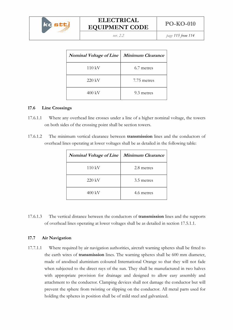
ELECTRICAL EQUIPMENT CODE
PO-KO-010
ver. 2.2 page 115 from 114
Nominal Voltage of Line Minimum Clearance
110 kV 6.7 metres
220 kV 7.75 metres
400 kV 9.3 metres
17.6 Line Crossings
17.6.1.1 Where any overhead line crosses under a line of a higher nominal voltage, the towers
on both sides of the crossing point shall be section towers.
17.6.1.2 The minimum vertical clearance between transmission lines and the conductors of
overhead lines operating at lower voltages shall be as detailed in the following table:
Nominal Voltage of Line Minimum Clearance
110 kV 2.8 metres
220 kV 3.5 metres
400 kV 4.6 metres
17.6.1.3 The vertical distance between the conductors of transmission lines and the supports
of overhead lines operating at lower voltages shall be as detailed in section 17.5.1.1.
17.7 Air Navigation
17.7.1.1 Where required by air navigation authorities, aircraft warning spheres shall be fitted to
the earth wires of transmission lines. The warning spheres shall be 600 mm diameter,
made of anodised aluminium coloured International Orange so that they will not fade
when subjected to the direct rays of the sun. They shall be manufactured in two halves
with appropriate provision for drainage and designed to allow easy assembly and
attachment to the conductor. Clamping devices shall not damage the conductor but will
prevent the sphere from twisting or slipping on the conductor. All metal parts used for
holding the spheres in position shall be of mild steel and galvanized.

ELECTRICAL EQUIPMENT CODE
PO-KO-010
ver. 2.2 page 116 from 114
17.8 Rights of Way and Tree Clearance
17.8.1.1 Overhead lines will be constructed over routes for which rights of way shall be
obtained as established by articles 23 – 31 of the law on energy. In accessing property
not in the ownership of the TSO, representatives of the TSO and any contractors
operating on behalf of the TSO shall do so in accordance with the requirements of the
code of practice for access to land and/or property.
18 Disputes Procedure
18.1.1.1 Disputes arising from the operation of this electrical equipment code shall be dealt
with in accordance with the rule on the resolution of complaints and disputes in
energy sector approved by the regulator as a means for resolving disputes arising
between parties in the power market.
19 Management of the Electrical Equipment Code
19.1.1.1 This electrical equipment code is prepared by the TSO and approved by the
regulator. It lays down the conditions that have to be met by all parties in the
circumstances covered by this code.
19.1.1.2 Revisions to this electrical equipment code will be undertaken by the operational
codes governance committee established in accordance with the rule on governance
procedures for technical/operational codes approved by the regulator. The TSO shall
take responsibility for incorporating any amendments that are agreed by the OCGC and
approved by the regulator and will issue amended versions of the code as required.
19.2 Unforeseen Circumstances
19.2.1 In this Electrical Equipment Code
19.2.1.1 If circumstances arise that the provisions of this electrical equipment code could
not reasonably have foreseen, the TSO shall, to the extent reasonably practicable in the
circumstances, consult promptly with all affected parties and the operational codes
governance committee (OCGC) in an effort to reach agreement as to what actions, if
any, should be taken. If agreement between the TSO and those parties cannot be
reached in the time available, the TSO acting as a reasonable and prudent operator
shall determine what actions, if any, should be taken. The TSO shall notify the parties
and the regulator of its decision and the reasons for it as soon as practicable.

ELECTRICAL EQUIPMENT CODE
PO-KO-010
ver. 2.2 page 117 from 114
19.2.1.2 Whenever the TSO makes a decision, it shall do so having regard, wherever possible,
to the views expressed by the other parties and, in any event, to what is reasonable in all
the circumstances.
19.2.1.3 After the event the TSO shall promptly refer all such unforeseen circumstances and
any such decisions to the operational codes governance committee for consideration
in accordance with section 19.1.1.2
19.2.2 Affecting the ability of parties to comply with this Code
19.2.2.1 Where a party is unable to comply with its obligations under this code for a force
majeure event, it may send a notice to all affected parties and to the regulator
detailing the reasons for it being unable to meet its obligations, why it believes these
reasons are a force majeure event and the time during which the force majeure event
will last.
19.2.2.2 During the period of force majeure, the party’s obligations shall be suspended to the
minimum extent required by the force majeure event.
19.2.2.3 If any party believes that the declaration of force majeure is unreasonable, he may
refer the matter to the regulator for review and the decision of the regulator shall be
final. In the event that the regulator determines that the reasons for non compliance
were not a force majeure event, then the obligations of the party claiming force majeure
will not be considered to have been suspended.
[End of the Document]