Electrical Drives I - AAST
20
Electrical Drives I Week 4-5-6: Solid state dc drives
Transcript of Electrical Drives I - AAST

Electrical Drives IWeek 4-5-6: Solid state dc drives
Motor- Load Matching
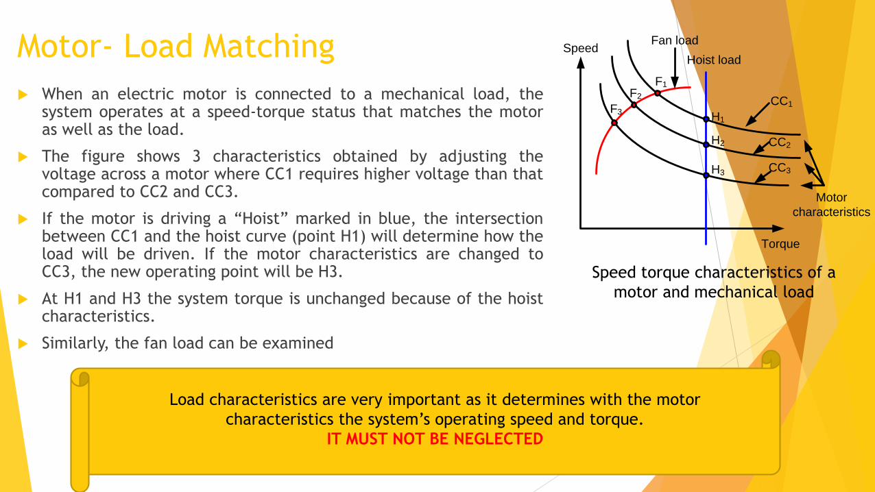
When an electric motor is connected to a mechanical load, thesystem operates at a speed-torque status that matches the motoras well as the load.
The figure shows 3 characteristics obtained by adjusting thevoltage across a motor where CC1 requires higher voltage than thatcompared to CC2 and CC3.
If the motor is driving a “Hoist” marked in blue, the intersectionbetween CC1 and the hoist curve (point H1) will determine how theload will be driven. If the motor characteristics are changed toCC3, the new operating point will be H3.
At H1 and H3 the system torque is unchanged because of the hoistcharacteristics.
Similarly, the fan load can be examined
Speed torque characteristics of a
motor and mechanical load
Load characteristics are very important as it determines with the motor
characteristics the system’s operating speed and torque.
IT MUST NOT BE NEGLECTED
Speed
Torque
Fan load
Hoist load
Motor
characteristics
H1
H2
H3
F1
F2
F3
CC1
CC2
CC3

Unidirectional and Bidirectional Operation
The load force is divided into 2 components.
1. one perpendicular to the road , F, producing a friction force.
(OPPOSING FORCE)
2. Another is 𝑭𝒍 which is parallel to the road and represents the load
torque exerted on the motor which depends on gravity and the
orientation of the road. (DUE TO MASS AND ACCELERATION)
𝑻𝒍 (load torque) in this case will be = 𝑭𝒍 * (radius of wheel)
If friction is neglected, the motor force, 𝑭𝑴 must match 𝑭𝒍 (𝑭𝑴 is
in opposite direction of 𝑭𝒍)
When the bus is moving downhill, the motor sees that the load
force is reversed. So the motor torque must then change its
direction to balance the load torque.
𝑭𝒎 pulls the system up the hill
Motor speed is unidirectional but in this example the
system torques are bidirectional
Fm
F
Fl
F
Fm
Fl
𝑭𝒍 pulls system down the hill
Example1:
𝐹𝑚 pulls the system up the hill
Fl pulls system down the hill
F producing a friction force

Unidirectional and Bidirectional Operation
Elevator moves passengers in up and down directions
The load force, 𝑭𝒍, is function of the passengers weight, cabin,
cables…etc.
In this case, 𝑭𝒍 is always unidirectional, and the motor force,
𝑭𝑴 is also unidirectional
The speed in this case is bidirectional
Torque is unidirectional but speed is bidirectional
Example2: Fm
Fl
Fm
MotionMotion
Fl

Four Quadrant
Operation in Electric
Drives Motor: machine torque is in the same
direction of the speed. The machine is
delivering mechanical power to load and is
consuming electrical power.
Generator: machine torque is in the
opposite direction of the speed. The
machine is delivering electrical power to
load and is consuming mechanical power.
LoadM
Tl
Tm
Power flow
LoadM
Tm
Power flow
Tl
LoadM
Tm
Power flow
Tl
LoadM
Tl
Tm
Power flow
Speed
Torque
Q2: speed same as Q1, 𝑻𝒍 is
reversed as well as 𝑻𝑴 . Machine
receives mechanical power from
load and acts as a generator
Q1: 𝑻𝒍 is opposite to 𝑻𝑴 ,
machine runs as motor and
power flows from machine
to load.
Q3: speed, 𝑻𝒍 and 𝑻𝑴 are reversed,
with respect to Q1. Machine runs as
motor and power flows from
machine to load.
Q4: speed is reversed, while 𝑻𝒍and 𝑻𝑴 are unchanged with
respect to Q1. Machine acts as
generator
• Q1 and Q3 machine: grinding machine,
horizontal conveyor belt
• Q1 and Q4 machine: elevator going up
and down

Torque-Speed Quadrant of Operation
m
Te
Te
m
Tem
Te
m
T
Direction of positive (forward) speed is arbitrary chosen
Quadrant 1Forward motoring
Quadrant 2Forward braking
Quadrant 3Reverse motoring
Quadrant 4Reverse braking
P = +ve
P = -ve
P = -ve
P = +ve
The beauty of the separately excited d.c. motor is the ease
with which it can be controlled.
• Firstly, the steady-state speed is determined by the applied
voltage, so we can make the motor run at any desired speed
in either direction simply by applying the appropriate
magnitude and polarity of the armature voltage.
• Secondly, the torque is directly proportional to the armature
current, which in turn depends on the difference between
the applied voltage 𝑉𝑡 and 𝐸𝑎. We can therefore make the
machine develop positive (motoring) or negative
(generating) torque simply by controlling the extent to
which the applied voltage is greater or less than 𝐸𝑎.
An armature voltage controlled d.c. machine is
therefore inherently capable of what is known as
‘four-quadrant’ operation,

Controlled Rectifier Fed DC Drives
To obtain variable DC voltage from fixed AC source
DC current flows in only 1 direction
For small motors (few kilowatts), single phase supply is used but with large motors three
phase supply is always used
The main power circuit consists of a six-thyristor bridge circuit which rectifies the incoming
a.c. supply to produce a d.c. supply to the motor armature. By altering the Wring angle of the
thyristors the mean value of the rectifies voltage can be varied, thereby allowing the motor
speed to be controlled.
T
Q1Q2
Q3 Q4
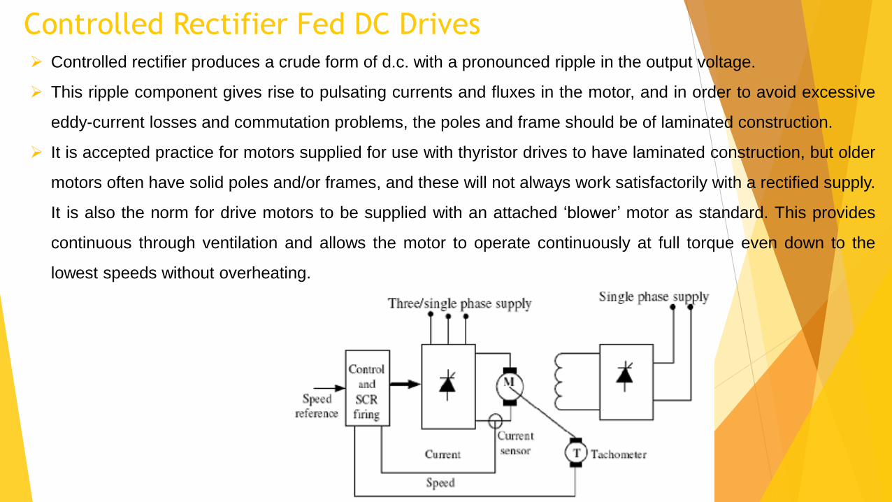
Controlled Rectifier Fed DC Drives Controlled rectifier produces a crude form of d.c. with a pronounced ripple in the output voltage.
This ripple component gives rise to pulsating currents and fluxes in the motor, and in order to avoid excessive
eddy-current losses and commutation problems, the poles and frame should be of laminated construction.
It is accepted practice for motors supplied for use with thyristor drives to have laminated construction, but older
motors often have solid poles and/or frames, and these will not always work satisfactorily with a rectified supply.
It is also the norm for drive motors to be supplied with an attached ‘blower’ motor as standard. This provides
continuous through ventilation and allows the motor to operate continuously at full torque even down to the
lowest speeds without overheating.
Controlled Rectifier Fed DC Drives
Single-phasesupply
+
Va
ia
M
S1 S2
S3S4
i1
ia
Ra
La
Vs
i2
Ea
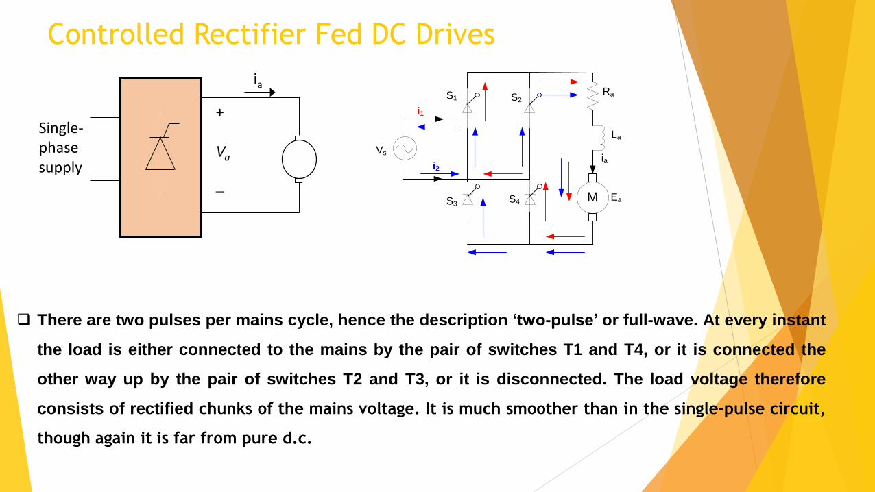
There are two pulses per mains cycle, hence the description ‘two-pulse’ or full-wave. At every instant
the load is either connected to the mains by the pair of switches T1 and T4, or it is connected the
other way up by the pair of switches T2 and T3, or it is disconnected. The load voltage therefore
consists of rectified chunks of the mains voltage. It is much smoother than in the single-pulse circuit,
though again it is far from pure d.c.
Controlled Rectifier Fed DC Drives
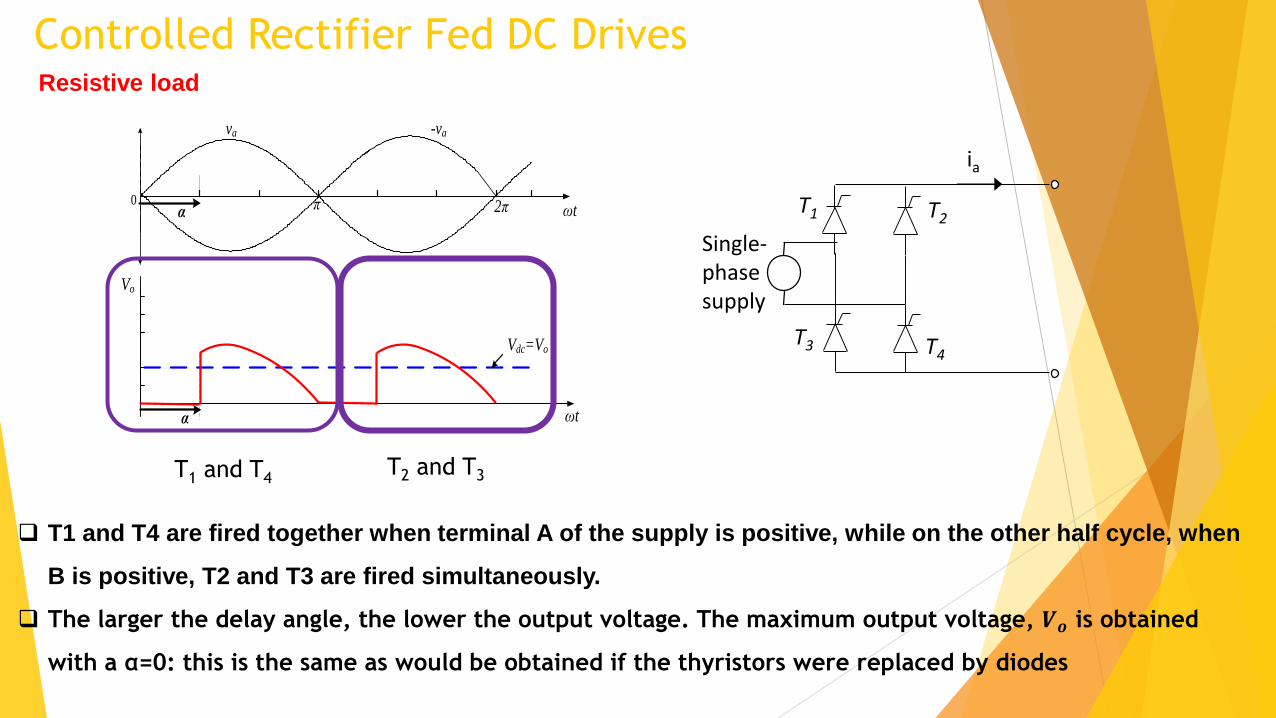
T1 and T4 are fired together when terminal A of the supply is positive, while on the other half cycle, when
B is positive, T2 and T3 are fired simultaneously.
The larger the delay angle, the lower the output voltage. The maximum output voltage, 𝑽𝒐 is obtained
with a α=0: this is the same as would be obtained if the thyristors were replaced by diodes
Single-phasesupply
T1
ia
T4
T2
T3
Resistive load
Vo
π0 2π
-va
α
α
ωt
Vdc=Vo
ωt
va
T1 and T4T2 and T3

Controlled Rectifier Fed DC DrivesResistive load
rmsdo VV 22
When the thyristors are replaced by diodes, the 𝑉𝑜 is
by:
Using thyristors the 𝑉𝑜 is by:
2
cos12
2
2
cos1
rmsdodc VVV
For a resistive load the d.c. voltage can be varied from a
maximum of 𝑉𝑑𝑜 down to zero by varying a from 0 to 180◦.
Vo
π0 2π
-va
α
α
ωt
Vdc=Vo
ωt
va
Vo
α
Vdc=Vo
ωt
the mean output voltage is NEVER
negative for any values of firing
angle.

Controlled Rectifier Fed DC Drives: Inductive (Motor) load motor loads are inductive, where current cannot change instantaneously.
The expected behavior of the converter with an inductive load is different than that of a resistive load, in which
the current can change instantaneously.
We can specify the output voltage waveform once we have fixed the delay angle α.
Based on the desired mean output voltage, α is being selected. Since the voltage relation is somehow complex
with inductive load, therefore we cannot give a simple general formula for the mean output voltage in terms of α.
This very undesirable: if for example we had set the speed of our unloaded d.c. motor to the target value by
adjusting the firing angle of the converter to produce the correct mean voltage, the last thing we would want is for
the voltage to fall when the load current drawn by the motor increases, as this would cause the speed to fall below
the target.
Fortunately however, it turns out that the output voltage waveform for a given α does become independent
of the load inductance once there is sufficient inductance to prevent the load current from falling to
zero. This condition is known as ‘continuous current’; and happily, many motor circuits do have sufficient
self-inductance to ensure that we achieve continuous current. Under continuous current conditions, the
output voltage waveform only depends on the Wring angle, and not on the actual inductance present.

Controlled Rectifier Fed DC Drives: Inductive (Motor) load We see that, as with the resistive load, the larger the delay
angle the lower the mean output voltage.
However, with the resistive load the output voltage was
never negative, however for short periods the output
voltage can now be negative.
This is because the inductance smoothes the current so that
at no time does it fall to zero. As a result, one pair of
thyristors is always conducting, so at every instant the load
is connected directly to the mains supply, and the load
voltage always consists of chunks of the supply voltage.
Vo
π0 2π
-va
α
α
ωt
Vdc=Vo
ωt
va
Vo
α
Vdc=Vo
ωt
15°
60°
cos22
cos rmsdodc VVV
If α is greater than
90˚ the mean
output voltage is
negative, could be
used in
regenerative mode
V relation in single phase full wave continuous mode at different firing
angles
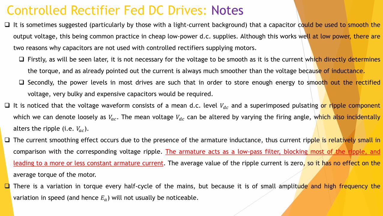
Controlled Rectifier Fed DC Drives: Notes It is sometimes suggested (particularly by those with a light-current background) that a capacitor could be used to smooth the
output voltage, this being common practice in cheap low-power d.c. supplies. Although this works well at low power, there are
two reasons why capacitors are not used with controlled rectifiers supplying motors.
Firstly, as will be seen later, it is not necessary for the voltage to be smooth as it is the current which directly determines
the torque, and as already pointed out the current is always much smoother than the voltage because of inductance.
Secondly, the power levels in most drives are such that in order to store enough energy to smooth out the rectified
voltage, very bulky and expensive capacitors would be required.
It is noticed that the voltage waveform consists of a mean d.c. level 𝑉𝑑𝑐 and a superimposed pulsating or ripple component
which we can denote loosely as 𝑉𝑎𝑐. The mean voltage 𝑉𝑑𝑐 can be altered by varying the firing angle, which also incidentally
alters the ripple (i.e. 𝑉𝑎𝑐).
The current smoothing effect occurs due to the presence of the armature inductance, thus current ripple is relatively small in
comparison with the corresponding voltage ripple. The armature acts as a low-pass filter, blocking most of the ripple, and
leading to a more or less constant armature current. The average value of the ripple current is zero, so it has no effect on the
average torque of the motor.
There is a variation in torque every half-cycle of the mains, but because it is of small amplitude and high frequency the
variation in speed (and hence 𝐸𝑎) will not usually be noticeable.
Controlled Rectifier Fed DC Drives: Notes
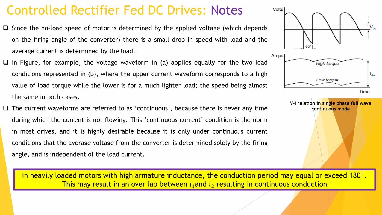
Since the no-load speed of motor is determined by the applied voltage (which depends
on the firing angle of the converter) there is a small drop in speed with load and the
average current is determined by the load.
In Figure, for example, the voltage waveform in (a) applies equally for the two load
conditions represented in (b), where the upper current waveform corresponds to a high
value of load torque while the lower is for a much lighter load; the speed being almost
the same in both cases.
The current waveforms are referred to as ‘continuous’, because there is never any time
during which the current is not flowing. This ‘continuous current’ condition is the norm
in most drives, and it is highly desirable because it is only under continuous current
conditions that the average voltage from the converter is determined solely by the firing
angle, and is independent of the load current.
In heavily loaded motors with high armature inductance, the conduction period may equal or exceed 180˚.
This may result in an over lap between 𝑖1and 𝑖2 resulting in continuous conduction
V-I relation in single phase full wave
continuous mode
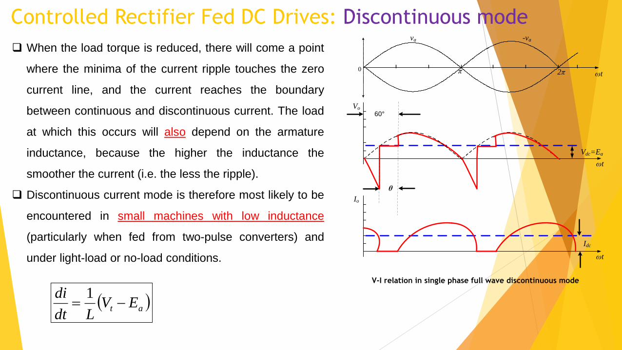
Controlled Rectifier Fed DC Drives: Discontinuous mode
When the load torque is reduced, there will come a point
where the minima of the current ripple touches the zero
current line, and the current reaches the boundary
between continuous and discontinuous current. The load
at which this occurs will also depend on the armature
inductance, because the higher the inductance the
smoother the current (i.e. the less the ripple).
Discontinuous current mode is therefore most likely to be
encountered in small machines with low inductance
(particularly when fed from two-pulse converters) and
under light-load or no-load conditions.
Vo
π0 2π
-va
θ
ωt
Vdc=Ea
ωt
va
Io
Idc
ωt
60°
at EVLdt
di
1V-I relation in single phase full wave discontinuous mode

Controlled Rectifier Fed DC Drives: Discontinuous mode
The following current relation shows that the rate of
change of current (i.e. the gradient of the lower graph) is
determined by the instantaneous difference between the
applied voltage 𝑉𝑡 and the 𝐸𝑎.
at EVLdt
di
1
Vo
π0 2π
-va
θ
ωt
Vdc=Ea
ωt
va
Io
Idc
ωt
60°Vt
Values of 𝑉𝑡 − 𝐸𝑎 are shown by the vertical hatchings in
the figure, from which it can be seen that if 𝑉𝑡 > 𝐸𝑎, the
current is increasing, while if 𝑉𝑡 < 𝐸𝑎 , the current is
falling. The peak current is thus determined by the area of
the upper or lower shaded areas of the upper graph.𝑉𝑡 > 𝐸𝑎 𝑉𝑡 < 𝐸𝑎
V-I relation in single phase full wave discontinuous mode

Controlled Rectifier Fed DC Drives: Discontinuous mode
In the discontinuous mode, the current falls to zero
before the next firing pulse arrives and during the
period shown as θ the motor floats free, its terminal
voltage during this time being 𝑬𝒂Vo
π0 2π
-va
θ
ωt
Vdc=Ea
ωt
va
Io
Idc
ωt
60°Vt
𝑉𝑡 > 𝐸𝑎 𝑉𝑡 < 𝐸𝑎
The average voltage in discontinuous mode is
higher than that of the continuous mode and
hence the speed is higher in the discontinuous
mode despite both having the same firing angle.
In continuous mode a load increase can be met by
an increased armature current without affecting
the voltage (and hence speed), the situation is
different when the current is discontinuous. In the
discontinuous mode, the only way that the
average current can increase is when speed (and
hence 𝑬𝒂) falls so that the shaded areas in the
figure become larger. V-I relation in single phase full wave discontinuous mode
Controlled Rectifier Fed DC Drives: Discontinuous mode
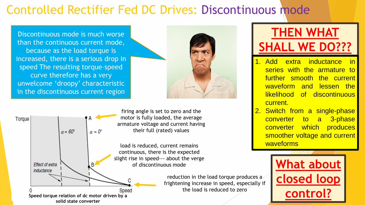
Discontinuous mode is much worse
than the continuous current mode,
because as the load torque is
increased, there is a serious drop in
speed The resulting torque–speed
curve therefore has a very
unwelcome ‘droopy’ characteristic
in the discontinuous current region
firing angle is set to zero and the
motor is fully loaded, the average
armature voltage and current having
their full (rated) values
load is reduced, current remains
continuous, there is the expected
slight rise in speed--- about the verge
of discontinuous mode
reduction in the load torque produces a
frightening increase in speed, especially if
the load is reduced to zero
THEN WHAT
SHALL WE DO???1. Add extra inductance in
series with the armature to
further smooth the current
waveform and lessen the
likelihood of discontinuous
current.
2. Switch from a single-phase
converter to a 3-phase
converter which produces
smoother voltage and current
waveforms
What about
closed loop
control?Speed torque relation of dc motor driven by a
solid state converter

Discontinous
CurrentContinous Current
α1
α2
α3
α4
α1> α2> α3
Torque
Speed
Speed torque relation of dc motor driven
by a solid state converter
Controlled Rectifier Fed DC Drives:
T
Forward
motoring
Forward
regeneration