Electrical Distribution System Analysis Dr. Ganesh Kumbhar … · 2018-11-02 · Electrical...
15
Electrical Distribution System Analysis Dr. Ganesh Kumbhar Department of Electrical Engineering Indian Institute of Technology, Roorkee Lecture - 02 Components of Distribution System Substation and Busbar Layouts Students, welcome to this second lecture of the course Electrical Distribution System Analysis. In the first lecture we have seen following topics, we have seen the introduction of electrical distribution system where we were studied which part of the power system we can call it as a electrical distribution system. (Refer Slide Time: 00:47) Then we have seen the structure of the distribution system, where we have classified the distribution system into two parts that is primary distribution system and secondary distribution system. And we have seen that primary over distribution system is basically ranges from 4 kV to 33 kV, most probably it is 11 kV. And then secondary distribution system we know that it is three-phase four wire system and three phase voltage is 400 volt and single phase voltage is 230 volt. Then we have studied why distribution system analysis is required because we already studied the power system analysis. And as compare to power system analysis what are the different things these distribution system has that is why we have to study distribution system analysis separately.
Transcript of Electrical Distribution System Analysis Dr. Ganesh Kumbhar … · 2018-11-02 · Electrical...
Electrical Distribution System AnalysisDr. Ganesh Kumbhar
Department of Electrical EngineeringIndian Institute of Technology, Roorkee
Lecture - 02Components of Distribution System Substation and Busbar Layouts
Students, welcome to this second lecture of the course Electrical Distribution System
Analysis. In the first lecture we have seen following topics, we have seen the
introduction of electrical distribution system where we were studied which part of the
power system we can call it as a electrical distribution system.
(Refer Slide Time: 00:47)
Then we have seen the structure of the distribution system, where we have classified the
distribution system into two parts that is primary distribution system and secondary
distribution system. And we have seen that primary over distribution system is basically
ranges from 4 kV to 33 kV, most probably it is 11 kV. And then secondary distribution
system we know that it is three-phase four wire system and three phase voltage is 400
volt and single phase voltage is 230 volt.
Then we have studied why distribution system analysis is required because we already
studied the power system analysis. And as compare to power system analysis what are
the different things these distribution system has that is why we have to study
distribution system analysis separately.
So, there are different things like we have seen that your distribution systems is radial
one. Unlike your transmission system which is basically interconnected one. Then we
have seen the ratio of R by X is higher in case of distribution system. Then distribution
system lines are un-transposed, loads are highly unbalanced. Then we have seen there are
large number of buses that is compare to transmission system. Then there are many
components like regulator, capacitors, distributor generators are present in the
distribution system.
Then the loads in the distribution system we need to cons consider them as a voltage
dependent load, but in case of transmission system we might have considered only of
constant power kind of load. Then we have seen that nowadays there are many
components because of smart grid they are getting introduced into the distribution
system. And because of that because of those component your distribution system is
becoming active from passive one.
Then we have seen the motivation and objectives to study this particular course. And
more motivation part we have seen that there is gradual development in the area of our
distribution system analysis from last 3 decades. There are many sophisticated
algorithms have been developed, we also seen that there is continuous improvement in
computational facilities available. There are continuous development in optimization
algorithm and it motivates to have a different set of algorithm for the analysis of
distribution system. Also, as compared to of transmission system since the size of
distribution systems is very large we need to have fast and simple methods to analyze the
distribution system.
Then we have seen the course content and in the core content we have seen that this
particular course is classified into 4 chapters. First chapter is related to study of
distribution substation layouts and distribution feeder configuration and introduction to
the distribution system. Then we have seen second chapter it is basically on approximate
methods of distribution system analysis. Third chapter is basically on modeling of
distribution system components and fourth chapter is on short circuit and load flow
analysis of distribution system. And then we have seen various references.
In this particular lecture we will focus on distributions system substations.
(Refer Slide Time: 04:53)
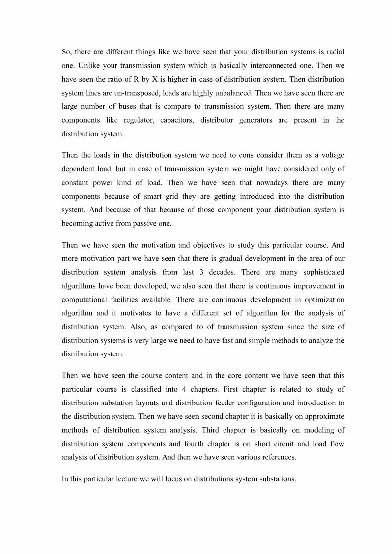
So, if you see of in this particular slide I have shown you the layout of distribution
system substation. And if you see this layout there are different component, they have
been shown and in this figure if you see there is one sub transmission line which may be
say 66 or 33 kV is coming from the left-hand side. And after that line is connected to
what is called as disconnector switch. Basically it gives us visible disconnection of the
components so, that during the maintenance the switch will be visible.
This disconnect switch can be on load or upload disconnect switch after that it is
connected to the voltage transformer. Then it is connected to the current transformer and
the purpose of this voltage and current transformer is to measure the voltages and
currents into the system. And this voltages are in currents are basically required for
relaying as well as measurement purpose.
Then this line is connected to the circuit breaker. So, basically this is your circuit breaker
here and generally in case of 33 kV by 11 kV substation this circuit breaker is of vacuum
circuit breaker kind of a breaker. We know that this circuit breaker basically operate
during the faulty condition. So, whenever there is fault relay will change the fault and it
will change signal to the circuit breaker and this circuit breaker will operate.
Then you can see that it is connected to the power transformer here. This power
transformer is step down your voltage to the required level. In this case it might be 33 by
11 kV transformers. This transformer may be having facility of tap changing and this tap

changer can be on load on load tap changer that is OLTC or upload tap changer. If it is
upload tap changer then you know you need to disconnect this transformer if you want to
change the tap, but if it is all on load tap changer that is OLTC then this tap will be
operated on load.
Then this connection step down connection will be given to the metal clad switch gear
and then after this switch gear the lines will be going out to the distribution system
feeder. And they will be spread over your distribution system to distribute the electrical
energy. If you see the schematic diagram or one line diagram of this particular
distribution substation although, component like disconnect switch is shown here.
Then there is voltage transformer shown here then there is current transformer it is
shown here. Then circuit breaker will be shown by a small square box, then there is
power transformer and then components of metal clad switch gear are shown it in this
particular dotted box. And this particular arrangement is called as single bus bar single
breaker arrangement.
So, you can see that in this case whenever you want to do some kind of maintenance on
this particular bus or if there is fault on this particular bus or if there is any fault on any
of the breaker then you need to shut down whole substation ok; this is drawback of this.
So, the reliability of this kind of single breaker and single bus bar arrangement will be
very low ok. So, that is why people choose different kinds of arrangement for substation
bus configuration.

(Refer Slide Time: 08:49)
So, arrangement which can be chosen are listed here. There are different arrangement
one is single bus single breaker arrangement, split bus single breaker arrangement, main
bus transfer bus arrangement, double bus double breaker arrangement, double bus single
breaker arrangement, a ring bus and there is breaker and half scheme.
The different reasons to choose different arrangements or different configurations are
listed here. The first reason is cost be because the cost of different layouts or different
configuration which are listed here they are different. Then the reliability of different
scheme they are different. Operational flexibility is third reason while choosing the
different configuration. Maintenance, importance of the substation and future expansions
all these are actually reasons based on which you will choose different substation
configurations or substation bus layouts.
(Refer Slide Time: 10:13)
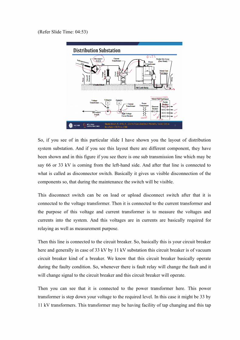
The first and foremost substation layout is actually single bus single breaker
arrangement, where there is only one bus and for each outgoing circuit there is only one
circuit breaker. So, only one bus and for each circuit which is going out of that bus or
which is connected to that bus there is only one circuit breaker.
So, if you see advantages and disadvantages of this particular configuration; the first
advantage of this particular configuration is low cost because if you can see there is only
one bus bar and at each outgoing circuit from this bus particular bus bar there is one
breaker is required. So, number of breaker requires are low in this case. Then if you see
the relaying protection is also simple. However, whenever there is fault on bus or if there
is fault on any circuit breaker you need to shut down whole substation. So, this is
actually of disadvantage of it, you need to shut down whole substation whenever there is
fault on bus bar or there is fault on any circuit breaker.
Entire substation need shut down for maintenance and bus extension. So, if you want to
do the maintenance or extension of this bus; extension means if you want to connect
some more lines to this particular bus you need to shut down whole substation. So, this is
again one more disadvantage of this particular layout. It can be used where loads can be
interrupted since the reliability is low this can be used wherever loads can be interrupted
without any disturbance, then this kind of substation can be used. Or whenever there is

some kind of alternate arrangement if it is available for different loads then also this
substation configuration can be chosen.
To improve the reliability of this layout people, what people do they split this bus into
two parts. So, if you see this configuration instead of single bus you what you can do you
can divide this bus into two parts. So, in this figure if you see this bus is divided into two
part and there is it is they are connected by normally open circuit breakers. So, normally
the circuit breaker will be open.
This will be closed whenever of required and because of this you can see that whenever
there is maintenance or whenever there is fault on some bus we can still feed half of the
circuit without any disturbance. So, during the maintenance of this bus part or if there is
fault on this particular bus you can still feed power to these remaining circuits. So,
reliability will get improved by splitting the bus. The advantage of this is cost is very
low.
(Refer Slide Time: 13:40)
Now, to improve reliability further we can divide bus into two parts. What you can
further do we can have two buses, these two buses are called as first bus is called as main
bus which is shown here in this particular figure and then there is transfer bus. All the
circuits are normally connected to the main bus so, this circuit will be carrying power to
this path.
It will be carrying current through this particular path which is shown by a red color. So,
if you see the advantage and disadvantage, disadvantages of this particular configuration.
The advantages are it is again low-cost configuration as compared to other component
configuration which we will see. Any circuit breaker can be taken out for maintenance.
So, whenever if you want to maintenance on this particular circuit breaker you can easily
take it out and then this circuit will be connected to the transfer bus. And this tie bus will
be closed and then actually for this particular circuit power will be flowing through this
path.
So, as compared to single bus scheme the reliability of this scheme is more. If you see
the disadvantages, the first disadvantage is it requires one extra circuit breaker for bus
tie. So, here we need one extra circuit breaker for connection of transfer bus. Then entire
substation results in shut shutdown in case of failure of any bus or any circuit breaker. In
this case since both bus are to be connected in the circuit because these transfer bus is
just basically part of the main bus when it when the circuit breaker is closed. So,
whenever there is failure on one of the bus both buses need to be taken out of the circuit
and entire substation will go out of the circuit.
Then all the circuit connected to the transfer bur results transfer bus results in outages
when there is fault on any of the circuit. Since, in this case since these circuits are not
protected by a circ circuit breaker because of that whenever there is fault on one of the
line you need to actually open this circuit breaker here. And because of that all the
circuits which are connected to the transfer bus they will go out of the circuit. See this is
our these are the disadvantages of the this particular scheme which is main and transfer
bus arrangement. Now, there is third are main which is called as double bus single
breaker arrangement.

(Refer Slide Time: 16:46)
In this particular if you see a particular scheme if you see the there are two number of
buses which are shown in this figure. Then there is one tie breaker here and for each
outgoing line you can see that there is one breaker. So, that is why since each outgoing
circuit is having single breaker this is called as in double bus single breaker scheme.
Now, if you see the advantages of this particular scheme; it has operational flexibility
and reliability due to two buses. Since, there are two buses any circuit can be connected
to of any of the bus that gives us operational flexibility. Any bus can be isolated for
maintenance. So, if you want to disconnect this bus you have then you can easily
disconnect this bus and you can do the of maintenance operation.
Circuit can be easily transferred from one bus to another bus since you are having these
switches here. So, using this circuit you can easily of transfer the circuit one circuit from
one bus to the another bus, but if you see the disadvantages of this particular one
configuration. Again in this case we need one extra circuit breaker for bus tie. So, here it
is shown this is extra circuit breaker for bus tie.
Then you can see that for each outgoing circuit there are 4 switches. So, this is 1 2 3 and
4 switches for each outgoing circuit. It gives higher maintenance cost as well as space
required for this particular substation, it will be high. Also there are since many switches
are used there are high chances of bus fault. So, higher expressed exposure to bus fault it
is another reason.
In case of failure of line circuit breakers then all the circuits which are connected to this
bus need to be taken out for service, this is disadvantage of this scheme. Then failure of
tie circuit breaker takes entire substation out of service. So, whenever there is failure on
tie circuit breaker you need to take entire substation out of service. This is disadvantage
of this particular scheme that is double bus single breaker arrangement.
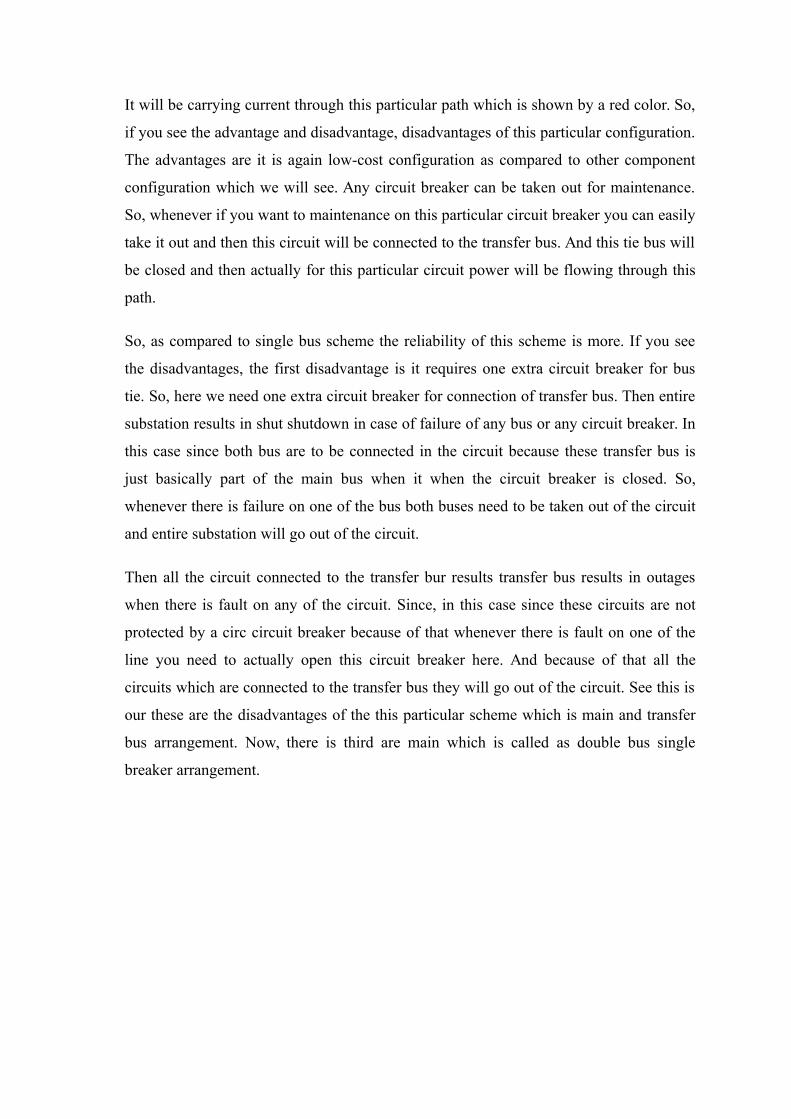
(Refer Slide Time: 19:28)
The next arrangement is double bus double breaker. So, if you can see this arrangement
in the into this particular figure there are two buses that is why this arrangements is
called a double bus arrangement. And for each outgoing line or for each outgoing circuit
you can see that for particular one circuit you need two breakers. So, this is actually that
is why this is double breaker also. So, double bus and double breaker scheme.
If you see the advantages of this scheme each line has two dedicated circuit breakers. So,
if as I told you there are circuit breaker which are dedicated to each line. Therefore, there
is higher reliability of this particular scheme. Circuit can be connected to any bus. So,
this circuit can be either connected to this bus through the circuit breaker or maybe it can
be connected to this bus through this circuit breaker it. So, it can be connected to the
either of the circuit breaker which gives higher flexibility of operation.
Any line can be taken out of the circuit for maintenance. So, in this case you can take
any line out of the circuit for maintenance purpose. This has very high reliability because
for each line we are having two circuit breaker and without any disconnection we can
connect any circuit to any bus using operation of this circuit breakers. So, this gives
higher reliability. Higher operational flexibility already told you because you are in to
breakers line can be connected to any of the buses.
But if you see the disadvantage of this particular scheme the it is cost involved. So, this
is most expensive scheme of all the scheme which we are going to see because of for
each outgoing circuit we need two dedicated circuit breakers. Also there are two buses
and because of this particular scheme is most expensive kind of scheme.
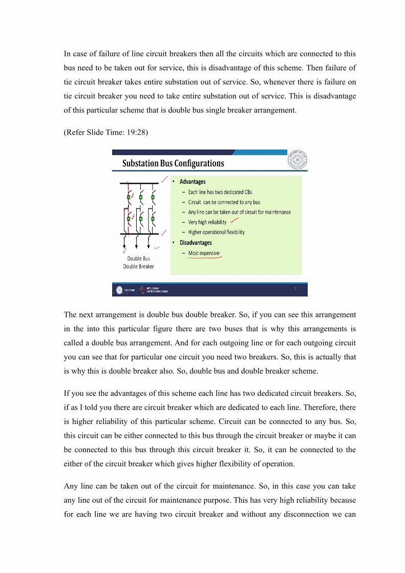
(Refer Slide Time: 21:45)
Next scheme is breaker and a half scheme. In this particular scheme if you observe they
are using two buses like two bus configuration. However, for two outgoing circuits so,
this is 1 2 outgoing circuit, we need 3 circuit breaker. So, 1 2 and 3 there are these are
three circuit breakers. So, for two outgoing lines we need 3 circuit breakers that is why
for each outgoing line we need one dedicated circuit breaker plus half from middle
circuit breaker. So, that is why this scheme is called as breaker and a half scheme.
Now, if you see the advantages and disadvantages of the scheme. As compared to other
configuration it gives higher of flexibility and reliability, but not as high as double
breaker and double bus scheme. Simple in operation and no disconnect switch operation
is required. So, these are actually known as disconnect switches. So, in this case
disconnect switch operation is not required if you want to connect to any of the bus. So,
we need only circuit breaker operation for connection or disconnection purpose.

Any bus can be taken out of for maintenance. So, if you can see this cam scheme any bus
can be taken out of circuit for maintenance. If you want to take this bus out of for
maintenance these both these lines which are connected can be actually failed through
the circuit breaker by closing this middle circuit breaker and the current will flow like
this. And you can do the maintenance on bus number 1.
All the circuit remain in service during bus failure. So, any of the bus if it fails all the
circuits can be connected to the other bus. So, all the circuit will remain in service. Bus
side circuit bus side CB failure removes only one circuit. So, whenever there is failure on
bus side circuit breaker only it will remove only one circuit breaker because other circuit
will remain into service.
However, if you see the disadvantage of this scheme the protection and relaving relaying
will be little bit involved, because protection scheme will be complete complex here.
Another disadvantage of this scheme it is expensive. So, as compared to other scheme
except double bus and double breaker scheme this scheme is bit expensive. But highest
cost will be for double bus and double breaker arrangement. So, after double bus and
double breaker arrangement this is the most expensive scheme.
(Refer Slide Time: 25:05)
And the last arrangement is called as ring bus arrangement. In this case the bus circuit
breakers are arranged in ring fashion which is shown like this. And if you observe for
each outgoing circuit we need one circuit breaker. So, if there are six outgoing lines we

need six breaker. So, as shown in figure there are six outgoing lines and for these six
outgoing lines there are six circuit breakers.
So, if you see advantages and disadvantages of this particular scheme. So, if you see the
advantage first advantage that is one breaker per circuit. So, only one circuit breaker is
required per circuit. So, it is economic. Still it can provide higher flexibility of operation
as well as higher reliability because whenever there is if any circuit breaker if you want
to take it for maintenance without disturbing supply of any of the circuit. So, this is
advantage of this particular scheme. So, that is any circuit breaker can be taken out for
maintenance without disconnecting any circuit.
Then next advantage is actually switching is done by breaker. So, in this case also we do
not need switching by your disconnecting switches. So, only circuit breakers can be used
for switching operations so, these are advantage. And if you see the disadvantages of this
scheme, even though it is cheap you will get protection or relaying will be relatively
complex for this particular scheme.
Another disadvantage is that fault on one circuit during circuit breaker maintenance ring
gets separated into two parts. So, whenever there is fault one say this circuit you need to
open these two circuit breakers. And if there is another circuit breaker during the
maintenance you are open then you can see that there are of it is forming two parts of the
buses. So, your bus will get divided into two parts.
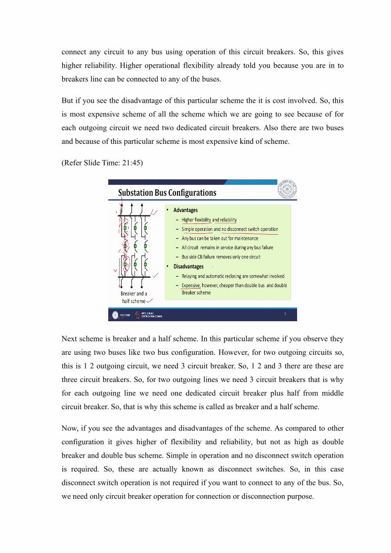
(Refer Slide Time: 27:48)
Now, if you see how these schemes can be used for different kinds of substations. So,
here I have shown one substation where this is your high voltage side and this is your
low voltage side and then this is connected by two transformers. In this case you can see
that for reliability purpose this yours of bus is divided into two parts. So, it is called as
split bus arrangement which is connected by a of normally open kind of circuit breaker.
So, the in this particular scheme even if there is one transformer or for maintenance or
even if there is no supply from any of those input circuits still the power will be available
for outgoing circuits. So, this is the advantage of this circuit. However, whenever there is
fault on any of the bus or if there is fault on any of the circuit breaker of outgoing circuit
that particular bus section need to be taken out of the service. And you need to shut down
the lines which are connected to this particular section of the bus.
Then to improve the reliability further what you can do, you can use the scheme which is
shown in the this particular figure which is shown on the right hand side; where at high
voltage side you are used this ring bus kind of configuration and at the voltage side we
have used split bus arrangement where the bus is split into two parts. Basically, it is into
three parts to improve the reliability and we also used main bus. So, this is your main bus
and transfer bus arrangement to improve the reliability. Also if you observe there are
three incoming lines which improves your reliability further and there are three
transformers one of them is just analyzed not connected to the circuit.
So, whenever there is one transformer out for maintenance or because of fault you can
still feed the power by energizing the transformer which is basically your spare
transformer. So, because of spare transformer main bus transfer bus arrangement and
ring bus arrangement at input side the reliability of this particular substation will be
higher.
(Refer Slide Time: 30:41)
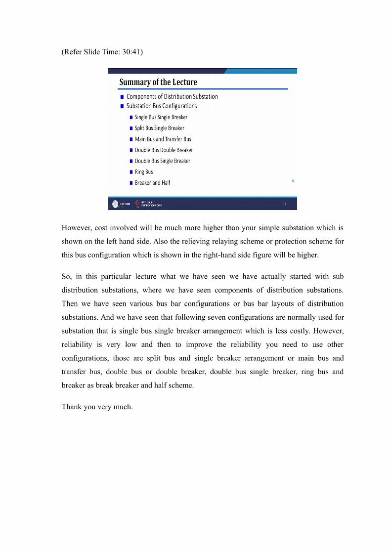
However, cost involved will be much more higher than your simple substation which is
shown on the left hand side. Also the relieving relaying scheme or protection scheme for
this bus configuration which is shown in the right-hand side figure will be higher.
So, in this particular lecture what we have seen we have actually started with sub
distribution substations, where we have seen components of distribution substations.
Then we have seen various bus bar configurations or bus bar layouts of distribution
substations. And we have seen that following seven configurations are normally used for
substation that is single bus single breaker arrangement which is less costly. However,
reliability is very low and then to improve the reliability you need to use other
configurations, those are split bus and single breaker arrangement or main bus and
transfer bus, double bus or double breaker, double bus single breaker, ring bus and
breaker as break breaker and half scheme.
Thank you very much.


![GANESH B. KUMBHAR PH.D. - Channel ipeople.iitr.ernet.in/facultyresume/GANESH_KUMBHAR_WEB.pdf · [14] G. B. Kumbhar, S.V. Kulkarni, R. Escarela-Perez, and E. Campero-Littlewood, “Applications](https://static.fdocuments.net/doc/165x107/5ecf7fce718cb02e6c772356/ganesh-b-kumbhar-phd-channel-14-g-b-kumbhar-sv-kulkarni-r-escarela-perez.jpg)


![Deepak Kumbhar [June 11 th , 2009]](https://static.fdocuments.net/doc/165x107/5681624e550346895dd29947/deepak-kumbhar-june-11-th-2009.jpg)