
Electrical connection systems - Şafak Elektrik · Klauke aspires to its own high standard. We have...
197
Electrical connection systems Copper tubular cable lugs and connectors 10 Tubular cable lugs 10 Tubular cable lugs for switchgear connections 16 Angle tubular cable lugs 17 Connectors 21 Insulated tubular cable lugs und connectors 25 Tubular cable lugs and connectors, blue connection ® 28 Tubular cable lugs and compression joints for solid conductors 30 Tubular cable lugs and connectors for fine stranded conductors 33 Tool application chart 38 Tubular cable lugs and connectors - nickel, stainless steel 46 Tubular cable lugs and connectors - stainless steel 48 Tubular cable lugs and connectors - nickel 50 Tool application chart 53 Copper compression cable lugs and connectors acc. to DIN 54 Compression cable lugs acc. to DIN 46235 56 Angle compression cable lugs 58 Compression cable lugs, special type 62 Compression joints acc. to DIN 46267, part 1 and similar versions 64 Tool application chart 69 Copper terminals, connectors and pin terminals acc. to DIN 72 Solderless terminals acc. to DIN 46234 74 Insulated solderless terminals 76 Solderless terminals, fork and pin type 78 Insulated solderless terminals for meter connections 80 Solderless connectors acc. to DIN 46341, part 1 80 Tool application chart 82 Sleeves for compacted conductors and sector-shaped conductors - copper 86 Aluminium compression cable lugs and connectors acc. to DIN 92 Aluminium compression cable lugs acc. to DIN 46329 and similar versions 94 Aluminium compression joints acc. to DIN 46267 part 2 and similar versions 97 Aluminium reduction compression joints 99 Aluminium compression joints, full tension 101 Aluminium compression cable lugs and connectors for Al/St cables DIN EN 50182 102 Tool application chart 103 Aluminium/copper compression cable lugs and connectors 106 Aluminium/copper compression cable lugs 108 Aluminium/copper compression joints 111 Bi-metallic washer 114 Tool application chart 115 Clamps and screw connectors 116 Punched cable lugs - copper 118 Screw connectors with soldering hole - brass 119 Parallel groove clamps - copper 120 C- and H-shaped clamps - copper 122 Screw connector for shielded copper wires 124 Screw connectors for street lighting - brass 124 Screw connectors, high-resistant aluminium alloy 125 Compact tab connectors, high resistant aluminium alloy 130 Tool application chart 133 Cable end-sleeves 136 Cable end-sleeves DIN 46228, part 1 and part 2 138 Insulated cable-end sleeves acc. to DIN 46228, part 4 and similar versions 141 Insulated cable end-sleeves for short circuit resistant conductors 146 Insulated twin cable-end sleeves 147 Insulated cable-end sleeves, strips and tapes 148 Tool application chart 150 Cable connections, insulated and non insulated 154 Insulated terminals 156 Non insulated flat connectors 167 Flexible connectors 172 Tool application chart 175 Assortments 178 Pocket boxes with cable end-sleeves 180 Pocket boxes with insulated cable end-sleeves 180 Assortment boxes with cable end-sleeves 185 Assortment boxes with insulated cable-end sleeves 186 Assortment boxes with tubular and compression cable lugs 189 Assortment boxes with insulated terminals 190 Steel carrying cases / bags 192 L-BOXXes 198 9 1
Transcript of Electrical connection systems - Şafak Elektrik · Klauke aspires to its own high standard. We have...

Electrical connection systemsCopper tubular cable lugs and connectors 10Tubular cable lugs 10Tubular cable lugs for switchgear connections 16Angle tubular cable lugs 17Connectors 21Insulated tubular cable lugs und connectors 25Tubular cable lugs and connectors, blue connection® 28Tubular cable lugs and compression joints for solid conductors 30Tubular cable lugs and connectors for fine stranded conductors 33Tool application chart 38
Tubular cable lugs and connectors - nickel, stainless steel 46Tubular cable lugs and connectors - stainless steel 48Tubular cable lugs and connectors - nickel 50Tool application chart 53
Copper compression cable lugs and connectors acc. to DIN 54Compression cable lugs acc. to DIN 46235 56Angle compression cable lugs 58Compression cable lugs, special type 62Compression joints acc. to DIN 46267, part 1 and similar versions 64Tool application chart 69
Copper terminals, connectors and pin terminals acc. to DIN 72Solderless terminals acc. to DIN 46234 74Insulated solderless terminals 76Solderless terminals, fork and pin type 78Insulated solderless terminals for meter connections 80Solderless connectors acc. to DIN 46341, part 1 80Tool application chart 82
Sleeves for compacted conductors and sector-shaped conductors - copper 86
Aluminium compression cable lugs and connectors acc. to DIN 92Aluminium compression cable lugs acc. to DIN 46329 and similar versions 94Aluminium compression joints acc. to DIN 46267 part 2 and similar versions 97Aluminium reduction compression joints 99Aluminium compression joints, full tension 101Aluminium compression cable lugs and connectors for Al/St cables DIN EN 50182 102Tool application chart 103
Aluminium/copper compression cable lugs and connectors 106Aluminium/copper compression cable lugs 108Aluminium/copper compression joints 111Bi-metallic washer 114Tool application chart 115
Clamps and screw connectors 116Punched cable lugs - copper 118Screw connectors with soldering hole - brass 119Parallel groove clamps - copper 120C- and H-shaped clamps - copper 122Screw connector for shielded copper wires 124Screw connectors for street lighting - brass 124Screw connectors, high-resistant aluminium alloy 125Compact tab connectors, high resistant aluminium alloy 130Tool application chart 133
Cable end-sleeves 136Cable end-sleeves DIN 46228, part 1 and part 2 138Insulated cable-end sleeves acc. to DIN 46228, part 4 and similar versions 141Insulated cable end-sleeves for short circuit resistant conductors 146Insulated twin cable-end sleeves 147Insulated cable-end sleeves, strips and tapes 148Tool application chart 150
Cable connections, insulated and non insulated 154Insulated terminals 156Non insulated flat connectors 167Flexible connectors 172Tool application chart 175
Assortments 178Pocket boxes with cable end-sleeves 180Pocket boxes with insulated cable end-sleeves 180Assortment boxes with cable end-sleeves 185Assortment boxes with insulated cable-end sleeves 186Assortment boxes with tubular and compression cable lugs 189Assortment boxes with insulated terminals 190Steel carrying cases / bags 192
L-BOXXes 198
9
1

In brief
`` Everything from a single source, from development to production
`` Best electrical conductivity thanks to electrolytic copper
`` Available for all cross sections and in many special versions
`` Tested to international standards
Copper tubular cable lugs and connectors
THE CLASSIC - COPPER TUBULAR CABLE LUGSNot every product becomes a classic at Klauke. Only the best ones. Tubular cable lugs
made from high-quality electrolytic copper have been part of the Klauke standard range
since 1960. The hallmarks: We handle all phases, from development to production. We
monitor each and every step. The result: The certified classic remains - in every version.
Electrical connection systems
10

➊
➋
➍
➌
➎
➏
` The system - Klauke connectors
At Klauke all products are matched to one another and we
manufacture in our own factories. We think in your work
steps – and produce everything systematically. Every cable
lug, every tool for the perfect connection.
◾ Full flexibility through solutions for all conductor classes to
DIN EN 60228
◾ For cables with compacted round conductors, cables
with sector-shaped conductors and to suit individual
requirements
◾ A single source - for everything from the cable lug to the
tool for professional electrical installations
` The preparation - Traditional quality
The best material is the basis for quality products.
For our classics we use - as for all Klauke products -
exclusively high-quality material from certified suppliers. You
get all our cable lugs with the optimum features. To achieve
this, we manufacture using a special annealing process.
◾ Optimum conductivity, high loading capacity and increased
safety thanks to high-quality materials
◾ Outstanding processing properties
` The proof - independent quality tests
Klauke aspires to its own high standard. We have this verified
by several independent inspection authorities and have put
ourselves through the tough IEC tests - with success.
◾ IEC (International Electric Commission): The IEC is an
advisory board for standards in the electrical engineering
and electronics sector. The certifications encompass all
areas of electrical engineering that have to meet especially
high demands.
◾ UL (Underwriters Laboratories): UL is an independent
organisation that examines and certifies products for
safety. The certification is particularly important on the
American market.
◾ DNV (Det Norske Veritas) and GL (Germanischer Lloyd):
DNV and GL have now merged to form the world’s largest
consulting company for onshore and offshore systems.
➊ Source material
➋ Folding and crimping
➌ Punching
➍ Annealing
➎ Tinned end product
➏ After crimping
11
1

Electrical connection systemsCopper tubular cable lugs and connectors
Nominal cross section
mm²Size of bolt dia.
Part No.
Dimension mm Weight/ 100 pcs.
~ kgPacking unit/pcsd1 a b d2 d4 c1 c2 l
0.75
M3 91R3 1.3 6 6.0 3.2 2.8 3.25 4.0 12 0.060 100
M4 91R4 1.3 6 6.5 4.3 2.8 4.00 5.0 13 0.060 100
M5 91R5 1.3 6 7.5 5.3 2.8 4.75 5.5 14 0.060 100
1.5
M3 92R3 1.8 6 6.5 3.2 3.3 3.25 4.0 12 0.080 100
M4 92R4 1.8 6 6.5 4.3 3.3 4.00 5.0 13 0.080 100
M5 92R5 1.8 6 7.5 5.3 3.3 4.75 5.5 14 0.080 100
M6 92R6 1.8 6 9.0 6.5 3.3 6.50 6.5 16 0.090 100
2.5
M3 93R3 2.3 6 7.5 3.2 4.2 3.25 4.0 12 0.120 100
M4 93R4 2.3 6 7.5 4.3 4.2 4.00 5.0 13 0.120 100
M5 93R5 2.3 6 8.5 5.3 4.2 4.75 5.5 14 0.130 100
M6 93R6 2.3 6 9.5 6.5 4.2 6.50 6.5 16 0.150 100
M8 93R8 2.3 6 13.0 8.5 4.2 7.75 9.5 20 0.180 100
4
M4 94R4 3.0 8 8.5 4.3 5.0 4.75 5.5 18 0.210 100
M5 94R5 3.0 8 9.0 5.3 5.0 4.75 6.0 18 0.213 100
M6 94R6 3.0 8 10.0 6.5 5.0 6.50 6.5 19 0.220 100
M8 94R8 3.0 8 13.0 8.5 5.0 8.50 9.5 22 0.280 100
6
M4 95R4 4.0 9 9.5 4.3 6.0 5.00 5.5 18 0.290 100
M5 95R5 4.0 9 9.5 5.3 6.0 6.00 6.0 19 0.300 100
M6 95R6 4.0 9 10.0 6.5 6.0 7.00 6.5 19 0.300 100
M8 95R8 4.0 9 14.0 8.5 6.0 8.50 9.5 22 0.320 100
Tubular cable lugs, Cu, standard type
` Cable lug for fine-stranded round conductors, e.g. to DIN EN 60228 Cl. 5` Simple processing thanks to inspection hole for monitoring full conductor
insertion
Characteristics▪ Annealed material optimises material and crimping properties▪ Simple and safe connection due to flat contact surfaces and internal chamfer▪ Item identification on cable lug
Material▪ Copper (EN13600)
Surface▪ Tin-plated to protect against corrosion
Technical instructions▪ Tool: see page 38
12

Nominal cross section
mm²Size of bolt dia.
Part No.
Dimension mm Weight/ 100 pcs.
~ kgPacking unit/pcsd1 a b d2 d4 c1 c2 l
0.75
M3 91C3 1.3 6 6.0 3.2 2.8 3.25 4.0 12 0.06 100
M4 91C4 1.3 6 6.5 4.3 2.8 4.00 5.0 13 0.05 100
M5 91C5 1.3 6 7.5 5.3 2.8 4.75 5.5 14 0.06 100
1.5
M3 92C3 1.8 6 6.5 3.2 3.3 3.25 4.0 12 0.07 100
M4 92C4 1.8 6 6.5 4.3 3.3 4.00 5.0 13 0.07 100
M5 92C5 1.8 6 7.5 5.3 3.3 4.75 5.5 14 0.07 100
M6 92C6 1.8 6 9.0 6.5 3.3 6.50 6.5 16 0.08 100
2.5
M3 93C3 2.3 6 7.5 3.2 4.2 3.25 4.0 12 0.12 100
M4 93C4 2.3 6 7.5 4.3 4.2 4.00 5.0 13 0.11 100
M5 93C5 2.3 6 8.5 5.3 4.2 4.75 5.5 14 0.12 100
M6 93C6 2.3 6 9.5 6.5 4.2 6.50 6.5 16 0.10 100
4
M4 94C4 3.0 8 8.5 4.3 5.0 4.75 5.5 17 0.19 100
M5 94C5 3.0 8 9.0 5.3 5.0 4.75 6.0 17 0.19 100
M6 94C6 3.0 8 10.0 6.5 5.0 6.50 6.5 19 0.21 100
M8 94C8 3.0 8 13.0 8.5 5.0 8.50 9.5 22 0.24 100
6
M4 95C4 4.0 9 9.5 4.3 6.0 5.00 5.5 18 0.27 100
M5 95C5 4.0 9 9.5 5.3 6.0 6.00 6.0 19 0.32 100
M6 95C6 4.0 9 10.0 6.5 6.0 7.00 6.5 19 0.27 100
M8 95C8 4.0 9 14.0 8.5 6.0 8.50 9.0 22 0.31 100
10
M5 96C5 4.5 10 12.0 5.5 7.0 6.50 7.5 22 0.45 100
M6 96C6 4.5 10 12.0 6.5 7.0 6.50 7.5 22 0.41 100
M8 96C8 4.5 10 15.0 8.5 7.0 10.00 10.0 25 0.52 100
16
M5 97C5 5.5 13 12.0 5.5 8.5 5.50 6.5 26 0.81 100
M6 97C6 5.5 13 12.0 6.5 8.5 6.25 7.5 27 0.81 100
M8 97C8 5.5 13 15.0 8.5 8.5 8.50 9.5 29 0.90 100
Tubular cable lugs, Cu, fork type
` Cable lug to 6 mm² for fine-stranded round conductors, 10 mm² and 16 mm² for multi-stranded round conductors to DIN EN 60228
` Simple fork-type mounting` Simple processing thanks to inspection hole to check the inserted conductor
Characteristics▪ Annealed material optimises material and crimping properties▪ Simple and safe connection due to flat contact surfaces and internal chamfer▪ Item identification on cable lug
Material▪ Copper (EN13600)
Surface▪ Tin-plated to protect against corrosion
Technical instructions▪ Tool: see page 38
13
1

Electrical connection systemsCopper tubular cable lugs and connectors
Nominal cross section
mm²Size of bolt dia.
Part No.
Dimension mm Weight/ 100 pcs.
~ kgPacking unit/pcsd1 a b d2 d4 c1 c2 l
6
M5 1R5 3.5 9 10 5.5 6.5 6.50 7.5 21 0.50 100
M6 1R6 3.5 9 12 6.5 6.5 6.50 7.5 21 0.47 100
M8 1R8 3.5 9 15 8.5 6.5 10.00 10.0 23 0.54 100
M10 1R10 3.5 9 17 10.5 6.5 12.00 12.0 25 0.59 100
M12 1R12 3.5 9 19 13.0 6.5 13.00 13.0 28 0.63 100
10
M5 2R5 4.5 10 12 5.5 7.0 6.50 7.5 22 0.50 100
M6 2R6 4.5 10 12 6.5 7.0 6.50 7.5 22 0.49 100
M8 2R8 4.5 10 15 8.5 7.0 10.00 10.0 25 0.58 100
M10 2R10 4.5 10 17 10.5 7.0 12.00 12.0 27 0.62 100
M12 2R12 4.5 10 19 13.0 7.0 13.00 13.0 29 0.64 100
16
M5 3R5 5.5 13 12 5.5 8.5 5.50 6.5 26 0.84 100
M6 3R6 5.5 13 12 6.5 8.5 6.25 7.5 27 0.86 100
M8 3R8 5.5 13 15 8.5 8.5 8.50 9.5 29 0.93 100
M10 3R10 5.5 13 17 10.5 8.5 10.50 11.5 31 0.99 100
M12 3R12 5.5 13 19 13.0 8.5 12.00 13.0 33 1.02 100
25
M5 4R5 7.0 15 14 5.5 10.0 7.50 7.5 30 1.22 25
M6 4R6 7.0 15 14 6.5 10.0 7.50 7.5 30 1.20 100
M8 4R8 7.0 15 16 8.5 10.0 10.00 10.0 32 1.31 100
M10 4R10 7.0 15 18 10.5 10.0 12.00 12.0 34 1.57 100
M12 4R12 7.0 15 19 13.0 10.0 13.00 13.0 35 1.39 25
M14 4R14 7.0 15 21 15.0 10.0 14.50 14.5 38 1.49 25
35
M6 5R6 8.5 17 17 6.5 12.0 7.50 7.5 32 1.85 100
M8 5R8 8.5 17 17 8.5 12.0 10.00 10.0 34 2.00 100
M10 5R10 8.5 17 19 10.5 12.0 12.00 12.0 37 2.13 100
M12 5R12 8.5 17 21 13.0 12.0 13.00 13.0 38 2.12 100
M14 5R14 8.5 17 21 15.0 12.0 14.50 14.5 40 2.18 25
M16 5R16 8.5 17 26 17.0 12.0 16.00 16.0 42 2.24 25
See next page
Tubular cable lugs, Cu, standard type
` For multi-stranded round conductors, e.g. to DIN EN 60228 Cl. 2` For pre-rounded multi-stranded sector shaped conductors` Ideal cable lug for control cabinet construction` In combination with EKM 60 ID suitable for fine-stranded conductors
Characteristics▪ Annealed material optimises material and crimping properties▪ To DIN EN 61373 class 1B vibration-tested▪ Simple and safe connection due to flat contact surfaces and internal chamfer▪ Item identification on cable lug
Material▪ Copper (EN13600)
Surface▪ Tin-plated to protect against corrosion
Technical instructions▪ Tool: see page 38▪ Sleeves for compacted conductors and sleeves for 3-core and 4-core cables, see
chapter „Sleeves for compacted conductors and sector shaped conductors - Cu“
Additional information▪ Also available as featured article with inspection hole, part number appendix „MS“
14

Nominal cross section
mm²Size of bolt dia.
Part No.
Dimension mm Weight/ 100 pcs.
~ kgPacking unit/pcsd1 a b d2 d4 c1 c2 l
50
M6 6R6 10.0 19 20 6.5 14.0 10.00 10.0 37 3.00 25
M8 6R8 10.0 19 20 8.5 14.0 10.00 10.0 37 2.93 50
M10 6R10 10.0 19 20 10.5 14.0 12.00 12.0 39 3.08 50
M12 6R12 10.0 19 23 13.0 14.0 13.00 13.0 43 3.23 50
M14 6R14 10.0 19 23 15.0 14.0 14.50 14.5 45 3.32 25
M16 6R16 10.0 19 28 17.0 14.0 16.00 16.0 46 3.38 25
M20 6R20 10.0 19 30 21.0 14.0 19.00 19.0 48 3.46 25
70
M6 7R6 12.0 21 23 6.5 16.5 10.00 10.0 43 4.49 25
M8 7R8 12.0 21 23 8.5 16.5 10.00 10.0 43 4.38 50
M10 7R10 12.0 21 23 10.5 16.5 12.00 12.0 44 4.54 50
M12 7R12 12.0 21 23 13.0 16.5 13.00 13.0 46 4.63 50
M14 7R14 12.0 21 23 15.0 16.5 14.50 14.5 48 4.76 25
M16 7R16 12.0 21 28 17.0 16.5 16.00 16.0 50 4.24 25
M20 7R20 12.0 21 30 21.0 16.5 19.00 19.0 53 5.09 25
95
M8 8R8 13.5 25 26 8.5 18.0 12.00 12.0 48 5.44 25
M10 8R10 13.5 25 26 10.5 18.0 12.00 12.0 48 5.40 50
M12 8R12 13.5 25 26 13.0 18.0 13.00 13.0 49 5.56 50
M14 8R14 13.5 25 26 15.0 18.0 14.50 14.5 51 5.62 25
M16 8R16 13.5 25 28 17.0 18.0 16.00 16.0 54 5.82 50
M20 8R20 13.5 25 36 21.0 18.0 22.00 22.0 60 6.71 25
120
M8 9R8 15.0 26 28 8.5 19.5 14.00 14.0 51 6.72 25
M10 9R10 15.0 26 28 10.5 19.5 14.00 14.0 51 6.57 50
M12 9R12 15.0 26 28 13.0 19.5 14.00 14.0 51 6.38 50
M14 9R14 15.0 26 28 15.0 19.5 15.00 15.0 52 6.45 25
M16 9R16 15.0 26 30 17.0 19.5 16.00 16.0 54 6.51 50
M20 9R20 15.0 26 36 21.0 19.5 22.00 22.0 63 7.74 25
150
M8 10R8 16.5 30 31 8.5 21.0 14.00 14.0 56 7.78 10
M10 10R10 16.5 30 31 10.5 21.0 14.00 14.0 56 7.62 10
M12 10R12 16.5 30 31 13.0 21.0 15.00 15.0 57 7.73 25
M14 10R14 16.5 30 31 15.0 21.0 15.00 15.0 57 7.64 10
M16 10R16 16.5 30 31 17.0 21.0 16.00 16.0 58 7.53 10
M20 10R20 16.5 30 36 21.0 21.0 22.00 22.0 66 8.80 10
185
M10 11R10 19.0 30 35 10.5 24.0 18.00 18.0 65 11.75 10
M12 11R12 19.0 30 35 13.0 24.0 18.00 18.0 65 11.82 10
M14 11R14 19.0 30 35 15.0 24.0 18.00 18.0 65 11.39 10
M16 11R16 19.0 30 35 17.0 24.0 18.00 18.0 65 11.24 25
M20 11R20 19.0 30 39 21.0 24.0 22.00 22.0 69 12.00 10
240
M10 12R10 21.0 35 39 10.5 26.0 21.50 19.0 72 14.72 10
M12 12R12 21.0 35 39 13.0 26.0 21.50 19.0 72 14.55 10
M14 12R14 21.0 35 39 15.0 26.0 21.50 19.0 72 14.24 10
M16 12R16 21.0 35 39 17.0 26.0 21.50 19.0 72 14.09 25
M20 12R20 21.0 35 39 21.0 26.0 21.50 19.0 72 13.60 10
300
M12 13R12 23.5 44 43 13.0 29.5 24.00 24.0 87 23.33 5
M14 13R14 23.5 44 43 15.0 29.5 24.00 24.0 87 23.14 5
M16 13R16 23.5 44 43 17.0 29.5 24.00 24.0 87 22.74 5
M20 13R20 23.5 44 43 21.0 29.5 24.00 24.0 87 22.19 5
400
M12 14R12 27.0 44 49 13.0 34.0 24.00 24.0 90 32.41 5
M14 14R14 27.0 44 49 15.0 34.0 24.00 24.0 90 32.24 5
M16 14R16 27.0 44 49 17.0 34.0 24.00 24.0 90 31.98 5
M20 14R20 27.0 44 49 21.0 34.0 24.00 24.0 90 31.41 5
Tubular cable lugs, Cu, standard type
15
1

Electrical connection systemsCopper tubular cable lugs and connectors
Nominal cross section
mm²Size of bolt dia. Part No.
Dimension mm Weight/ 100 pcs.
~ kgPacking unit/pcsd1 a b d2 d4 c1 c2 l
35M6
5SG6 8.5 17 15.0 6.5 12.0 7.5 7.5 32 1.78 25
50
6SG6 10.0 19 15.0 6.5 14.0 10.0 10.0 37 2.95 25
M8 6SG8 10.0 19 17.0 8.5 14.0 10.0 10.0 37 2.82 25
M10 6SG10 10.0 19 19.0 10.5 14.0 11.5 12.0 39 3.08 25
70
M6 7SG6 12.0 21 17.0 6.5 16.5 10.0 10.0 43 4.22 25
M8 7SG8 12.0 21 17.0 8.5 16.5 10.0 10.0 43 4.10 25
M10 7SG10 12.0 21 19.0 10.5 16.5 11.5 12.0 44 4.45 25
M12 7SG12 12.0 21 19.0 13.0 16.5 13.0 13.0 46 4.22 25
95
M6 8SG6 13.5 25 19.0 6.5 18.0 11.5 12.0 48 5.49 25
M8 8SG8 13.5 25 19.0 8.5 18.0 11.5 12.0 48 5.46 25
M10 8SG10 13.5 25 19.0 10.5 18.0 11.5 12.0 48 5.13 25
M12 8SG12 13.5 25 19.0 13.0 18.0 13.0 13.0 49 5.15 25
120
M6 9SG6 15.0 26 19.0 6.5 19.5 11.5 14.0 51 6.16 10
M8 9SG8 15.0 26 19.0 8.5 19.5 11.5 14.0 51 5.94 10
M10 9SG10 15.0 26 19.0 10.5 19.5 11.5 14.0 51 5.81 10
M12 9SG12 15.0 26 19.0 13.0 19.5 14.0 14.0 51 5.92 10
150
M6 10SG6 16.5 30 19.0 6.5 21.0 11.5 14.0 56 6.85 10
M8 10SG8 16.5 30 19.0 8.5 21.0 11.5 14.0 56 6.80 10
M10 10SG10 16.5 30 19.0 10.5 21.0 11.5 14.0 56 6.75 10
M12 10SG12 16.5 30 19.0 13.0 21.0 15.0 15.0 57 7.15 10
185
M10 11SG10 19.0 30 24.5 10.5 24.0 11.5 18.0 65 10.59 10
M12 11SG12 19.0 30 31.0 13.0 24.0 18.0 18.0 65 11.09 10
M16 11SG16 19.0 30 31.0 17.0 24.0 18.0 18.0 65 9.76 10
240
M10 12SG10 21.0 35 31.0 10.5 26.0 11.5 19.0 72 12.70 5
M12 12SG12 21.0 35 31.0 13.0 26.0 21.5 19.0 72 13.72 5
M16 12SG16 21.0 35 31.0 17.0 26.0 21.5 19.0 72 13.28 5
300
M10 13SG10 23.5 44 31.0 10.5 30.0 11.5 24.0 87 19.70 5
M12 13SG12 23.5 44 31.0 13.0 30.0 24.0 24.0 87 22.72 5
M16 13SG16 23.5 44 31.0 17.0 30.0 24.0 24.0 87 22.50 5
Tubular cable lugs for switchgear connections, standard type
` For multi-stranded, round conductors e.g. to DIN EN 60228` For pre-rounded multi-stranded sector shaped conductors` For connecting in switch cabinets with reduced connecting space` Narrow palm version manufactured without material loss` In combination with EKM 60 ID suitable for fine-stranded conductors
Characteristics▪ Annealed material optimises material and crimping properties▪ Simple and safe connection due to flat contact surfaces and internal chamfer
Material▪ Copper (EN13600)
Surface▪ Tin-plated to protect against corrosion
Technical instructions▪ Tool: see page 38▪ Sleeves for compacted conductors and sleeves for 3-core and 4-core cables, see
chapter „Sleeves for compacted conductors and sector shaped conductors - Cu“
Additional information▪ Also available as featured article with inspection hole, part number appendix „MS“
16

Nominal cross
section mm²Size of bolt dia.
Part No.
Dimension mm Weight/ 100 pcs.
~ kgPacking unit/pcsd1 a b d2 d4 c1 l3
6
M5 41R5 3.5 9 10 5.5 6.5 7.5 9 0.59 50
M6 41R6 3.5 9 12 6.5 6.5 7.5 10 0.58 50
M8 41R8 3.5 9 14 8.5 6.5 10.0 13 0.61 50
M10 41R10 3.5 9 17 10.5 6.5 12.0 15 0.65 50
M12 41R12 3.5 9 19 13.0 6.5 13.0 17 0.62 50
10
M5 42R5 4.5 10 12 5.5 7.0 6.5 10 0.57 50
M6 42R6 4.5 10 12 6.5 7.0 6.5 10 0.57 50
M8 42R8 4.5 10 15 8.5 7.0 10.0 13 0.63 50
M10 42R10 4.5 10 17 10.5 7.0 12.0 15 0.66 50
M12 42R12 4.5 10 19 13.0 7.0 13.0 18 0.81 50
16
M5 43R5 5.5 13 12 5.5 8.5 7.5 10 1.01 50
M6 43R6 5.5 13 12 6.5 8.5 7.5 11 1.01 50
M8 43R8 5.5 13 15 8.5 8.5 10.0 13 1.08 50
M10 43R10 5.5 13 17 10.5 8.5 12.0 15 1.09 50
M12 43R12 5.5 13 19 13.0 8.5 13.0 18 1.15 50
25
M5 44R5 7.0 15 14 5.5 10.0 7.5 11 1.40 25
M6 44R6 7.0 15 14 6.5 10.0 7.5 11 1.32 25
M8 44R8 7.0 15 16 8.5 10.0 10.0 13 1.44 25
M10 44R10 7.0 15 18 10.5 10.0 12.0 15 1.49 25
M12 44R12 7.0 15 19 13.0 10.0 13.0 18 1.44 25
M14 44R14 7.0 15 21 15.0 10.0 14.5 20 1.55 25
35
M6 45R6 8.5 17 17 6.5 12.0 7.5 11 2.05 25
M8 45R8 8.5 17 17 8.5 12.0 10.0 13 2.20 25
M10 45R10 8.5 17 19 10.5 12.0 12.0 15 2.28 25
M12 45R12 8.5 17 21 13.0 12.0 13.0 18 2.38 25
M14 45R14 8.5 17 21 15.0 12.0 14.5 20 2.41 25
M16 45R16 8.5 17 26 17.0 12.0 16.0 22 2.40 25
See next page
Angled tubular cable lugs, Cu, 90° angled, standard type
` For multi-stranded, round conductors e.g. to DIN EN 60228` For pre-rounded multi-stranded sector shaped conductors` Flat contact surface by special angle pressing technology` In combination with the EKM 60 ID suitable for fine stranded conductors
Characteristics▪ Annealed material optimises material and crimping properties▪ Simple cable entry due to internal chamfer▪ Item identification on cable lug
Material▪ Copper (EN13600)
Surface▪ Tin-plated to protect against corrosion
Technical instructions▪ Tool: see page 38▪ Sleeves for compacted conductors and sleeves for 3-core and 4-core cables, see
chapter „Sleeves for compacted conductors and sector shaped conductors - Cu“
Additional information▪ Also available as featured article with inspection hole, part number appendix „MS“
17
1

Electrical connection systemsCopper tubular cable lugs and connectors
Nominal cross
section mm²Size of bolt dia.
Part No.
Dimension mm Weight/ 100 pcs.
~ kgPacking unit/pcsd1 a b d2 d4 c1 l3
50
M6 46R6 10.0 19 20 6.5 14.0 10.0 13 3.34 25
M8 46R8 10.0 19 20 8.5 14.0 10.0 13 3.28 25
M10 46R10 10.0 19 20 10.5 14.0 12.0 16 3.47 25
M12 46R12 10.0 19 23 13.0 14.0 13.0 18 3.42 25
M14 46R14 10.0 19 23 15.0 14.0 14.5 20 3.55 25
M16 46R16 10.0 19 28 17.0 14.0 16.0 22 3.58 25
M20 46R20 10.0 19 30 21.0 14.0 19.0 24 3.15 25
70
M6 47R6 12.0 21 23 6.5 16.5 10.0 13 4.90 25
M8 47R8 12.0 21 23 8.5 16.5 10.0 14 4.80 25
M10 47R10 12.0 21 23 10.5 16.5 12.0 16 4.88 25
M12 47R12 12.0 21 23 13.0 16.5 13.0 18 4.99 25
M14 47R14 12.0 21 23 15.0 16.5 14.5 20 5.38 25
M16 47R16 12.0 21 28 17.0 16.5 16.0 22 5.35 25
M20 47R20 12.0 21 30 21.0 16.5 19.0 24 5.30 25
95
M8 48R8 13.5 25 26 8.5 18.0 12.0 14 5.89 25
M10 48R10 13.5 25 26 10.5 18.0 12.0 17 5.88 25
M12 48R12 13.5 25 26 13.0 18.0 13.0 18 5.93 25
M14 48R14 13.5 25 26 15.0 18.0 14.5 20 6.03 25
M16 48R16 13.5 25 28 17.0 18.0 16.0 22 6.17 25
M20 48R20 13.5 25 36 21.0 18.0 22.0 24 6.42 25
120
M8 49R8 15.0 26 28 8.5 19.5 14.0 16 7.26 10
M10 49R10 15.0 26 28 10.5 19.5 14.0 17 7.30 10
M12 49R12 15.0 26 28 13.0 19.5 14.0 18 7.19 10
M14 49R14 15.0 26 28 15.0 19.5 15.0 20 7.30 10
M16 49R16 15.0 26 30 17.0 19.5 16.0 22 7.35 10
M20 49R20 15.0 26 36 21.0 19.5 22.0 24 7.60 10
150
M8 50R8 16.5 30 31 8.5 21.0 14.0 16 8.41 10
M10 50R10 16.5 30 31 10.5 21.0 14.0 17 8.27 10
M12 50R12 16.5 30 31 13.0 21.0 15.0 18 8.34 10
M14 50R14 16.5 30 31 15.0 21.0 15.0 20 8.52 10
M16 50R16 16.5 30 31 17.0 21.0 16.0 22 8.62 10
M20 50R20 16.5 30 36 21.0 21.0 22.0 24 9.10 10
185
M10 51R10 19.0 30 35 10.5 24.0 18.0 22 12.17 10
M12 51R12 19.0 30 35 13.0 24.0 18.0 22 11.97 10
M14 51R14 19.0 30 35 15.0 24.0 18.0 22 11.77 10
M16 51R16 19.0 30 35 17.0 24.0 18.0 22 11.53 10
M20 51R20 19.0 30 39 21.0 24.0 22.0 24 12.00 10
240
M10 52R10 21.0 35 39 10.5 26.0 21.5 22 15.60 10
M12 52R12 21.0 35 39 13.0 26.0 21.5 22 15.60 10
M14 52R14 21.0 35 39 15.0 26.0 21.5 22 15.41 10
M16 52R16 21.0 35 39 17.0 26.0 21.5 22 15.18 10
M20 52R20 21.0 35 39 21.0 26.0 21.5 24 14.80 10
300
M12 53R12 23.5 44 43 13.0 29.5 24.0 24 23.60 5
M14 53R14 23.5 44 43 15.0 29.5 24.0 24 23.40 5
M16 53R16 23.5 44 43 17.0 29.5 24.0 24 20.99 5
M20 53R20 23.5 44 43 21.0 29.5 24.0 24 22.70 5
400
M12 54R12 27.0 44 49 13.0 34.0 24.0 24 32.53 5
M14 54R14 27.0 44 49 15.0 34.0 24.0 24 33.40 5
M16 54R16 27.0 44 49 17.0 34.0 24.0 24 32.60 5
M20 54R20 27.0 44 49 21.0 34.0 24.0 24 31.80 5
Angled tubular cable lugs, Cu, 90° angled, standard type
18

Nominal cross
section mm²Size of bolt dia. Part No.
Dimension mm Weight/ 100 pcs.
~ kgPacking unit/pcsd1 a b d2 d4 c1 l3
6
M5 41R545 3.5 9 10 5.5 6.5 7.5 9 0.60 50
M6 41R645 3.5 9 12 6.5 6.5 7.5 10 0.58 50
M8 41R845 3.5 9 14 8.5 6.5 10.0 13 0.68 50
M10 41R1045 3.5 9 17 10.5 6.5 12.0 15 0.70 50
M12 41R1245 3.5 9 19 13.0 6.5 13.0 17 0.70 50
10
M5 42R545 4.5 10 12 5.5 7.0 6.5 10 0.57 50
M6 42R645 4.5 10 12 6.5 7.0 6.5 10 0.57 50
M8 42R845 4.5 10 15 8.5 7.0 10.0 13 0.63 50
M10 42R1045 4.5 10 17 10.5 7.0 12.0 15 0.68 50
M12 42R1245 4.5 10 19 13.0 7.0 13.0 18 0.68 50
16
M5 43R545 5.5 13 12 5.5 8.5 7.5 10 1.01 50
M6 43R645 5.5 13 12 6.5 8.5 7.5 11 1.06 50
M8 43R845 5.5 13 15 8.5 8.5 10.0 13 1.15 50
M10 43R1045 5.5 13 17 10.5 8.5 12.0 15 1.09 50
M12 43R1245 5.5 13 19 13.0 8.5 13.0 18 1.15 50
25
M5 44R545 7.0 15 14 5.5 10.0 7.5 11 1.40 25
M6 44R645 7.0 15 14 6.5 10.0 7.5 11 1.32 25
M8 44R845 7.0 15 16 8.5 10.0 10.0 13 1.44 25
M10 44R1045 7.0 15 18 10.5 10.0 12.0 15 1.49 25
M12 44R1245 7.0 15 19 13.0 10.0 13.0 18 1.44 25
M14 44R1445 7.0 15 21 15.0 10.0 14.5 20 1.55 25
35
M6 45R645 8.5 17 17 6.5 12.0 7.5 11 2.05 25
M8 45R845 8.5 17 17 8.5 12.0 10.0 13 2.20 25
M10 45R1045 8.5 17 19 10.5 12.0 12.0 15 2.28 25
M12 45R1245 8.5 17 21 13.0 12.0 13.0 18 2.38 25
M14 45R1445 8.5 17 21 15.0 12.0 14.5 20 2.41 25
M16 45R1645 8.5 17 26 17.0 12.0 16.0 22 2.40 25
See next page
Angled tubular cable lugs, Cu, 45° angled, standard type
` For multi-stranded, round conductors e.g. to DIN EN 60228` For pre-rounded multi-stranded sector shaped conductors` Flat contact surface by special angle pressing technology
Characteristics▪ Annealed material optimises material and crimping properties▪ Simple cable entry due to internal chamfer▪ Item identification on cable lug
Material▪ Copper (EN13600)
Surface▪ Tin-plated to protect against corrosion
Technical instructions▪ Tool: see page 38▪ Sleeves for compacted conductors and sleeves for 3-core and 4-core cables, see
chapter „Sleeves for compacted conductors and sector shaped conductors - Cu“▪ In combination with EKM 60 ID suitable for fine-stranded conductors
Additional information▪ Also available as featured article with inspection hole, part number appendix „MS“
19
1
Electrical connection systemsCopper tubular cable lugs and connectors
Nominal cross section mm²
Size of bolt dia. Part No.
Dimension mm Weight/ 100 pcs.
~ kgPacking unit/pcsd1 a b d2 d4 c1 l3
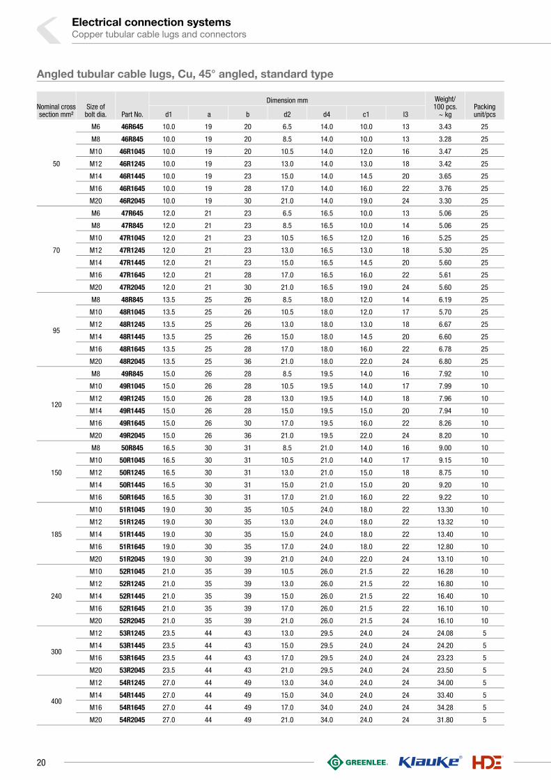
50
M6 46R645 10.0 19 20 6.5 14.0 10.0 13 3.43 25
M8 46R845 10.0 19 20 8.5 14.0 10.0 13 3.28 25
M10 46R1045 10.0 19 20 10.5 14.0 12.0 16 3.47 25
M12 46R1245 10.0 19 23 13.0 14.0 13.0 18 3.42 25
M14 46R1445 10.0 19 23 15.0 14.0 14.5 20 3.65 25
M16 46R1645 10.0 19 28 17.0 14.0 16.0 22 3.76 25
M20 46R2045 10.0 19 30 21.0 14.0 19.0 24 3.30 25
70
M6 47R645 12.0 21 23 6.5 16.5 10.0 13 5.06 25
M8 47R845 12.0 21 23 8.5 16.5 10.0 14 5.06 25
M10 47R1045 12.0 21 23 10.5 16.5 12.0 16 5.25 25
M12 47R1245 12.0 21 23 13.0 16.5 13.0 18 5.30 25
M14 47R1445 12.0 21 23 15.0 16.5 14.5 20 5.60 25
M16 47R1645 12.0 21 28 17.0 16.5 16.0 22 5.61 25
M20 47R2045 12.0 21 30 21.0 16.5 19.0 24 5.60 25
95
M8 48R845 13.5 25 26 8.5 18.0 12.0 14 6.19 25
M10 48R1045 13.5 25 26 10.5 18.0 12.0 17 5.70 25
M12 48R1245 13.5 25 26 13.0 18.0 13.0 18 6.67 25
M14 48R1445 13.5 25 26 15.0 18.0 14.5 20 6.60 25
M16 48R1645 13.5 25 28 17.0 18.0 16.0 22 6.78 25
M20 48R2045 13.5 25 36 21.0 18.0 22.0 24 6.80 25
120
M8 49R845 15.0 26 28 8.5 19.5 14.0 16 7.92 10
M10 49R1045 15.0 26 28 10.5 19.5 14.0 17 7.99 10
M12 49R1245 15.0 26 28 13.0 19.5 14.0 18 7.96 10
M14 49R1445 15.0 26 28 15.0 19.5 15.0 20 7.94 10
M16 49R1645 15.0 26 30 17.0 19.5 16.0 22 8.26 10
M20 49R2045 15.0 26 36 21.0 19.5 22.0 24 8.20 10
150
M8 50R845 16.5 30 31 8.5 21.0 14.0 16 9.00 10
M10 50R1045 16.5 30 31 10.5 21.0 14.0 17 9.15 10
M12 50R1245 16.5 30 31 13.0 21.0 15.0 18 8.75 10
M14 50R1445 16.5 30 31 15.0 21.0 15.0 20 9.20 10
M16 50R1645 16.5 30 31 17.0 21.0 16.0 22 9.22 10
185
M10 51R1045 19.0 30 35 10.5 24.0 18.0 22 13.30 10
M12 51R1245 19.0 30 35 13.0 24.0 18.0 22 13.32 10
M14 51R1445 19.0 30 35 15.0 24.0 18.0 22 13.40 10
M16 51R1645 19.0 30 35 17.0 24.0 18.0 22 12.80 10
M20 51R2045 19.0 30 39 21.0 24.0 22.0 24 13.10 10
240
M10 52R1045 21.0 35 39 10.5 26.0 21.5 22 16.28 10
M12 52R1245 21.0 35 39 13.0 26.0 21.5 22 16.80 10
M14 52R1445 21.0 35 39 15.0 26.0 21.5 22 16.40 10
M16 52R1645 21.0 35 39 17.0 26.0 21.5 22 16.10 10
M20 52R2045 21.0 35 39 21.0 26.0 21.5 24 16.10 10
300
M12 53R1245 23.5 44 43 13.0 29.5 24.0 24 24.08 5
M14 53R1445 23.5 44 43 15.0 29.5 24.0 24 24.20 5
M16 53R1645 23.5 44 43 17.0 29.5 24.0 24 23.23 5
M20 53R2045 23.5 44 43 21.0 29.5 24.0 24 23.50 5
400
M12 54R1245 27.0 44 49 13.0 34.0 24.0 24 34.00 5
M14 54R1445 27.0 44 49 15.0 34.0 24.0 24 33.40 5
M16 54R1645 27.0 44 49 17.0 34.0 24.0 24 34.28 5
M20 54R2045 27.0 44 49 21.0 34.0 24.0 24 31.80 5
Angled tubular cable lugs, Cu, 45° angled, standard type
20

Nominal cross section mm²
Part No.
Dimension mm Weight/ 100 pcs.
~ kg Packing unit/pcs d1 d4 l
0.75 17R 1.3 2.8 20 0.09 100
1.5 18R 1.8 3.3 25 0.12 100
2.5 19R 2.3 4.2 25 0.20 100
4 20R 3.0 5.0 25 0.26 100
6 21R 3.5 6.5 25 0.50 100
10 22R 4.5 7.0 30 0.72 100
16 23R 5.5 8.5 35 1.00 100
25 24R 7.0 10.0 40 1.41 50
35 25R 8.5 12.0 45 2.24 50
50 26R 10.0 14.0 50 3.36 50
70 27R 12.0 16.5 55 4.87 50
95 28R 13.5 18.0 60 5.91 25
120 29R 15.0 19.5 65 7.00 25
150 30R 16.5 21.0 70 8.12 10
185 31R 19.0 24.0 75 10.06 10
240 32R 21.0 26.0 85 13.82 10
300 33R 23.5 29.5 100 21.94 5
400 34R 27.0 34.0 100 29.65 5
Butt connectors, Cu, standard type
` For multi-stranded, round conductors e.g. to DIN EN 60228` For pre-rounded multi-stranded sector shaped conductors` Simple cable entry for internal chamfer
Characteristics▪ Simple and safe processing due to butt mark▪ Annealed material optimises material and crimping properties▪ Item identification on cable lug
Material▪ Copper (EN13600)
Surface▪ Tin-plated to protect against corrosion
Technical instructions▪ In combination with EKM 60 ID suitable for fine-stranded conductors▪ Tool: see page 38▪ Sleeves for compacted conductors and sleeves for 3-core and 4-core cables, see
chapter „Sleeves for compacted conductors and sector shaped conductors - Cu“
Additional information▪ Also available as featured article without buttmark, part number appendix „OM“
21
1

Electrical connection systemsCopper tubular cable lugs and connectors
Nominal cross section mm²
Part No.
Dimension mm Weight/ 100 pcs.
~ kg Packing unit/pcs d1 d4 l
1.5 148R 1.8 3.3 5 0.03 100
2.5 149R 2.3 4.2 5 0.04 100
4 150R 3.0 5.0 7 0.08 100
6 151R 4.0 6.0 7 0.09 100
10 152R 4.5 7.0 9 0.17 100
16 153R 5.5 8.5 10 0.28 100
25 154R 7.0 10.0 13 0.44 100
35 155R 8.5 12.0 16 0.78 100
50 156R 10.0 14.0 19 1.22 100
70 157R 12.0 16.5 19 1.62 50
95 158R 13.5 18.0 20 1.90 50
120 159R 15.0 19.5 22 2.28 50
150 160R 16.5 21.0 26 3.00 50
185 161R 19.0 24.0 30 4.37 50
240 162R 21.0 26.0 32 5.30 25
300 163R 23.5 29.5 36 8.05 25
Parallel connectors, Cu, standard type
` For multi-stranded round conductors, e.g. to DIN EN 60228 Cl. 2` Ideal for connecting differing cable cross-sections` Simple cable entry due to internal chamfer
Characteristics▪ Annealed material optimises material and crimping properties
Material▪ Copper (EN13600)
Surface▪ Tin-plated to protect against corrosion
Technical instructions▪ Tool: see page 38
Additional information▪ The stated nominal cross-section corresponds to the total cross-section of the cable▪ Additional conductor types and combinations on request
22

Nominal cross section mm²
Part No.
Dimension mm Weight/ 100 pcs.
~ kg Packing unit/pcs d1 d4 l l1
1.5 TV15 1.8 3.3 30 12 0.23 50
2.5 TV2.5 2.3 4.2 30 12 0.37 50
4 TV4 3.0 5.0 30 12 0.45 50
6 TV6 4.0 6.0 35 14 0.73 50
10 TV10 4.5 7.0 35 14 1.05 50
16 TV16 5.5 8.5 50 21 2.20 50
25 TV25 7.0 10.0 55 23 2.90 25
35 TV35 8.5 12.0 70 30 5.20 25
50 TV50 10.0 14.0 80 34 7.90 25
70 TV70 12.0 16.5 85 35 11.20 10
95 TV95 13.5 18.0 90 36 13.00 10
120 TV120 15.0 19.5 95 38 14.70 10
150 TV150 16.5 21.0 110 44 18.90 10
185 TV185 19.0 24.0 115 45 25.00 5
240 TV240 21.0 26.0 130 52 31.10 5
T-connectors, Cu, standard type
` For multi-stranded, round conductors e.g. to DIN EN 60228` For pre-rounded multi-stranded sector shaped conductors` Special version for cable tap conductors
Characteristics▪ Annealed material optimises material and crimping properties▪ Simple cable entry due to internal chamfer
Material▪ Copper (EN13600)
Surface▪ Tin-plated to protect against corrosion
Technical instructions▪ Tool: see page 38▪ Sleeves for compacted conductors and sleeves for 3-core and 4-core cables, see
chapter „Sleeves for compacted conductors and sector shaped conductors - Cu“
23
1

Electrical connection systemsCopper tubular cable lugs and connectors
Nominal cross section mm²
Part No.
Dimension mm Weight/ 100 pcs.
~ kg Packing unit/pcs d1 d4 l l1
1.5 KV15 1.8 3.3 30 12 0.320 25
2.5 KV2.5 2.3 4.2 30 12 0.490 25
4 KV4 3.0 5.0 30 12 0.650 25
6 KV6 4.0 6.0 35 14 0.950 25
10 KV10 4.5 7.0 35 14 1.350 25
16 KV16 5.5 8.5 50 21 2.950 25
25 KV25 7.0 10.0 55 23 4.000 15
35 KV35 8.5 12.0 70 30 6.900 15
50 KV50 10.0 14.0 80 34 10.400 15
70 KV70 12.0 16.5 85 35 14.600 15
95 KV95 13.5 18.0 90 36 17.100 15
120 KV120 15.0 19.5 95 38 19.400 5
150 KV150 16.5 21.0 110 44 24.100 5
185 KV185 19.0 24.0 115 45 32.100 5
240 KV240 21.0 26.0 130 52 41.100 5
Cross-connectors, Cu, standard type
` For multi-stranded round conductors, e.g. to DIN EN 60228 Cl. 2` For pre-rounded multi-stranded sector shaped conductors` Version for double cable tap conductors
Characteristics▪ Annealed material optimises material and crimping properties▪ Simple cable entry due to internal chamfer
Material▪ Copper (EN13600)
Surface▪ Tin-plated to protect against corrosion
Technical instructions▪ Tool: see page 38▪ Sleeves for compacted conductors and sleeves for 3-core and 4-core cables, see
chapter „Sleeves for compacted conductors and sector shaped conductors - Cu“
24

Nominal cross
section mm²Size of
bolt dia. Part No. Colour
Dimension mm weight 100 pcs. ~kg Cu
weight 100 pcs. ~kg Total
Packing unit/pcsd12 d13 d2 Gl1 l10
10
M5 602R5 7.0 9.0 5.5 35.5 17.0 0.50 0.548 25
M6 602R6 7.0 9.0 6.5 35.5 17.0 0.49 0.538 25
M8 602R8 7.0 9.0 8.5 42.0 17.0 0.58 0.628 25
M10 602R10 7.0 9.0 10.5 46.0 17.0 0.62 0.668 25
M12 602R12 7.0 9.0 13.0 49.0 17.0 0.64 0.688 25
16
M5 603R5 8.5 10.5 5.5 39.5 21.0 0.84 0.907 25
M6 603R6 8.5 10.5 6.5 41.3 21.0 0.86 0.927 25
M8 603R8 8.5 10.5 8.5 45.5 21.0 0.93 0.997 25
M10 603R10 8.5 10.5 10.5 49.5 21.0 0.99 1.057 25
M12 603R12 8.5 10.5 13.0 54.0 21.0 1.02 1.087 25
25
M5 604R5 10.0 12.0 5.5 45.0 24.0 1.22 1.312 25
M6 604R6 10.0 12.0 6.5 46.5 24.0 1.20 1.292 25
M8 604R8 10.0 12.0 8.5 51.0 24.0 1.31 1.402 25
M10 604R10 10.0 12.0 10.5 55.0 24.0 1.57 1.662 25
M12 604R12 10.0 12.0 13.0 57.0 24.0 1.39 1.482 25
M14 604R14 10.0 12.0 15.0 61.5 24.0 1.49 1.582 25
35
M6 605R6 12.0 14.5 6.5 49.5 27.0 1.85 2.010 25
M8 605R8 12.0 14.5 8.5 54.0 27.0 2.00 2.160 25
M10 605R10 12.0 14.5 10.5 59.0 27.0 2.13 2.290 25
M12 605R12 12.0 14.5 13.0 61.0 27.0 2.12 2.280 25
M14 605R14 12.0 14.5 15.0 64.5 27.0 2.18 2.340 25
M16 605R16 12.0 14.5 17.0 68.0 27.0 2.24 2.400 25
See next page
Insulated tubular cable lugs, Cu, standard type
` For multi-stranded round conductors, e.g. to DIN EN 60228 Cl. 2` For pre-rounded multi-stranded sector shaped conductors` No additional insulation of the crimped connection required` Is directly crimped with the insulation
Characteristics▪ Annealed material optimises material and crimping properties▪ Simple and safe connection due to flat contact surfaces and internal chamfer▪ Heat resistant to 105° C
Material▪ Cable lug: Copper to EN 13600▪ Insulation sleeve: PA, halogen-free
Surface▪ Tin-plated to protect against corrosion
Technical instructions▪ Tool: see page 40▪ Dimensions of tubular cable lugs can be found from page 14▪ Sleeves for compacted conductors and sleeves for 3-core and 4-core cables, see
chapter „Sleeves for compacted conductors and sector shaped conductors - Cu“
Additional information▪ Also available as featured article with inspection hole, part number appendix „MS“
25
1

Electrical connection systemsCopper tubular cable lugs and connectors
Nominal cross
section mm²Size of
bolt dia. Part No. Colour
Dimension mm Gewicht 100 St. ~kg
Cu
Gewicht 100 St. ~kg
Ges.Packing unit/
pcsd12 d13 d2 Gl1 l10
50
M6 606R6 14.0 16.5 6.5 59.0 32.0 3.00 3.220 25
M8 606R8 14.0 16.5 8.5 59.0 32.0 2.93 3.150 25
M10 606R10 14.0 16.5 10.5 63.0 32.0 3.08 3.300 25
M12 606R12 14.0 16.5 13.0 68.0 32.0 3.23 3.450 25
M14 606R14 14.0 16.5 15.0 71.5 32.0 3.32 3.540 25
M16 606R16 14.0 16.5 17.0 77.0 32.0 3.38 3.600 25
M20 606R20 14.0 16.5 21.0 83.5 32.0 3.46 3.680 25
70
M6 607R6 16.4 18.9 6.5 65.5 33.5 4.49 4.760 25
M8 607R8 16.4 18.9 8.5 65.5 33.5 4.38 4.650 25
M10 607R10 16.4 18.9 10.5 66.5 33.5 4.54 4.810 25
M12 607R12 16.4 18.9 13.0 70.5 33.5 4.63 4.900 25
M14 607R14 16.4 18.9 15.0 73.5 33.5 4.76 5.030 25
M16 607R16 16.4 18.9 17.0 78.5 33.5 4.24 4.510 25
M20 607R20 16.4 18.9 21.0 84.5 33.5 5.09 5.360 25
95
M8 608R8 17.8 20.8 8.5 74.0 40.0 5.44 5.85 25
M10 608R10 17.8 20.8 10.5 74.0 40.0 5.40 5.81 25
M12 608R12 17.8 20.8 13.0 76.0 40.0 5.56 5.97 25
M14 608R14 17.8 20.8 15.0 79.5 40.0 5.62 6.03 25
M16 608R16 17.8 20.8 17.0 84.0 40.0 5.82 6.23 25
M20 608R20 17.8 20.8 21.0 96.0 40.0 6.71 7.12 25
120
M8 609R8 19.3 22.3 8.5 80.5 41.5 6.72 7.18 10
M10 609R10 19.3 22.3 10.5 80.5 41.5 6.57 7.03 10
M12 609R12 19.3 22.3 13.0 80.5 41.5 6.38 6.84 10
M16 609R16 19.3 22.3 17.0 85.5 41.5 6.51 6.97 10
Insulated tubular cable lugs, Cu, standard type
26

Nominal cross section mm²
Part No. Colour
Dimension mm Gewicht 100 St. ~kg
Cu
Gewicht 100 St. ~kg
Ges. Packing unit/pcsd12 d13 l10
10 622R 7.0 9.0 42 0.72 0.84 25
16 623R 8.5 10.5 50 1.00 1.16 25
25 624R 10.0 12.0 57 1.41 1.63 25
35 625R 12.0 14.4 65 2.24 2.60 25
50 626R 14.0 16.4 72 3.36 3.81 25
70 627R 16.4 19.0 80 4.87 5.46 25
95 628R 17.8 20.8 87 5.91 6.74 25
Insulated butt connectors, Cu, standard type
` For multi-stranded round conductors, e.g. to DIN EN 60228 Cl. 2` For pre-rounded multi-stranded sector shaped conductors` No additional insulation of the crimped connection required` Is directly crimped with the insulation
Characteristics▪ With buttmarks for precise cable insertion▪ Annealed material optimises material and crimping properties▪ Simple cable entry due to internal chamfer▪ Heat resistant to 105° C
Material▪ Connector: Copper (EN 13600)▪ Insulation sleeve: PA, halogen-free
Surface▪ Tin-plated to protect against corrosion
Technical instructions▪ Tool: see page 40▪ Dimensions of butt connectors can be found on page 21▪ Sleeves for compacted conductors and sleeves for 3-core and 4-core cables, see
chapter „Sleeves for compacted conductors and sector shaped conductors - Cu“
27
1

Electrical connection systemsCopper tubular cable lugs and connectors
Nominal cross section
mm²Size of bolt dia.
Part No.
Dimension mm Weight/ 100 pcs.
~ kgPacking unit/pcsd1 a b d2 d4 c1 c2 l
6
M5 6B5 3.20 9.0 10.50 5.30 5.00 5.00 6.50 20.50 0.24 50
M6 6B6 3.20 9.0 11.00 6.40 5.00 6.00 8.00 22.00 0.26 50
M8 6B8 3.20 9.0 12.50 8.40 5.00 8.00 10.00 24.00 0.29 50
M10 6B10 3.20 9.00 14.00 10.50 5.00 10.00 11.50 25.50 0.30 50
10
M5 10B5 4.10 9.00 11.50 5.30 6.50 5.00 6.50 21.00 0.35 50
M6 10B6 4.10 9.00 12.00 6.40 6.50 6.00 8.00 22.50 0.39 50
M8 10B8 4.10 9.00 14.00 8.40 6.50 8.00 10.00 24.50 0.43 50
M10 10B10 4.10 9.00 15.00 10.50 6.50 10.00 11.50 26.00 0.44 50
16
M6 16B6 5.50 10.0 13.50 6.40 7.70 6.00 8.00 25.00 0.61 50
M8 16B8 5.50 10.0 15.00 8.40 7.70 8.00 10.00 27.00 0.65 50
M10 16B10 5.50 10.00 16.50 10.50 7.70 10.00 11.50 28.00 0.69 50
M12 16B12 5.50 10.00 18.50 13.00 7.70 12.00 13.00 29.50 0.72 50
25
M6 25B6 6.60 10.0 15.00 6.40 9.00 6.00 8.00 25.50 0.81 25
M8 25B8 6.60 10.0 16.00 8.40 9.00 8.00 10.00 27.50 0.88 50
M10 25B10 6.60 10.0 18.00 10.50 9.00 10.00 11.50 29.00 0.93 50
M12 25B12 6.60 10.0 19.50 13.00 9.00 12.00 13.00 30.50 0.97 25
35
M8 35B8 7.70 11.0 18.00 8.40 10.60 8.00 10.00 29.50 1.34 50
M10 35B10 7.70 11.0 19.50 10.50 10.60 10.00 11.50 31.00 1.42 50
M12 35B12 7.70 11.0 21.00 13.00 10.60 12.00 13.00 32.50 1.48 25
50
M8 50B8 9.20 11.0 19.00 8.40 12.40 8.00 10.00 31.00 1.87 25
M10 50B10 9.20 11.0 21.00 10.50 12.40 10.00 11.50 32.50 1.95 25
M12 50B12 9.20 11.0 23.00 13.00 12.40 12.00 13.00 34.00 2.05 25
70
M8 70B8 11.00 21.0 22.00 8.40 14.60 8.00 10.00 41.50 3.17 25
M10 70B10 11.00 21.0 24.00 10.50 14.60 10.00 11.50 43.00 3.33 25
M12 70B12 11.00 21.0 25.00 13.00 14.60 12.00 13.00 44.50 3.46 25
M16 70B16 11.00 21.0 28.00 17.00 14.60 15.00 17.00 48.50 3.73 10
95
M10 95B10 13.00 21.0 26.00 10.50 17.00 10.00 11.50 44.50 4.55 25
M12 95B12 13.00 21.0 28.00 13.00 17.00 12.00 13.00 46.00 4.75 25
M16 95B16 13.00 21.0 30.00 17.00 17.00 15.00 17.00 50.00 5.01 10
See next page
Tubular cable lugs, blue connection®, Cu
` For compacted multi-stranded round conductors to DIN EN 60228` Accurate assignment of crimping tool/crimping die through colour-coding
system` Fewer crimps due to max. crimping width` Reduced costs due to compact dimensions
Characteristics▪ Rigid design thanks to special shaped radius▪ Processing takes place without the use of additional sleeves▪ Annealed material optimises material and crimping properties▪ Simple and safe connection due to flat contact surfaces and internal chamfer
Material▪ Copper (EN13600)
Surface▪ Tin-plated to protect against corrosion
Technical instructions▪ Tool: see page 41
Additional information▪ 10-300 mm² IEC-tested
28

Rohrkabelschuhe, blue connection®, Cu
Nominal cross section
mm²Size of bolt dia.
Part No.
Dimension mm Weight/ 100 pcs.
~ kgPacking unit/pcsd1 a b d2 d4 c1 c2 l
120
M10 120B10 14.50 22.0 28.00 10.50 19.00 10.00 11.50 47.00 6.02 25
M12 120B12 14.50 22.0 29.50 13.00 19.00 12.00 13.00 48.50 6.26 25
M16 120B16 14.50 22.0 32.00 17.00 19.00 15.00 17.00 52.50 6.73 10
150M10 150B10 16.20 22.0 30.00 10.50 21.00 10.00 11.50 48.50 7.41 10
M12 150B12 16.20 22.0 32.00 13.00 21.00 12.00 13.00 50.00 7.71 10
185
M10 185B10 18.00 24.0 33.00 10.50 23.00 10.00 11.50 52.00 9.21 10
M12 185B12 18.00 24.0 33.00 13.00 23.00 12.00 13.00 53.50 9.43 10
M16 185B16 18.00 24.0 36.00 17.00 23.00 15.00 17.00 57.70 10.14 10
240M12 240B12 20.60 24.0 38.00 13.00 26.00 12.00 13.00 56.00 12.46 10
M16 240B16 20.60 24.0 38.00 17.00 26.00 15.00 17.00 60.00 13.24 10
300M12 300B12 23.10 33.0 41.00 13.00 28.00 12.00 13.00 67.00 14.39 5
M16 300B16 23.10 33.0 41.00 17.00 28.00 15.00 17.00 71.00 15.27 5
Nominal cross section mm²
Part No.
Dimension mm Weight/ 100 pcs.
~ kg Packing unit/pcsd1 d4 l
6 6B 3.20 5.00 25.00 0.255 50
10 10B 4.10 6.50 25.00 0.360 50
16 16B 5.50 7.70 27.00 0.543 50
25 25B 6.60 9.00 27.00 0.699 50
35 35B 7.70 10.60 28.00 1.026 50
50 50B 9.20 12.40 28.00 1.334 25
70 70B 11.00 14.60 48.00 3.065 25
95 95B 13.00 17.00 48.00 3.987 25
120 120B 14.50 19.00 50.00 5.157 25
150 150B 16.20 21.00 52.00 6.379 10
185 185B 18.00 23.00 56.00 7.889 10
240 240B 20.60 26.00 58.00 10.000 10
300 300B 23.10 28.00 76.00 13.079 5
Butt connectors, blue connection®, Cu
` For compacted multi-stranded round conductors, e.g. to DIN EN 60228 Cl. 2` Accurate assignment of crimping tool/crimping die through colour-coding
system` Fewer crimps due to max. crimping width` Reduced costs due to compact dimensions
Characteristics▪ Processing takes place without the use of additional sleeves▪ Annealed material optimises material and crimping properties▪ Simple cable entry due to internal chamfer
Material▪ Copper (EN13600)
Surface▪ Tin-plated to protect against corrosion
Technical instructions▪ Tool: see page 41
Additional information▪ 10-300 mm² IEC-tested
29
1

Electrical connection systemsCopper tubular cable lugs and connectors
Nominal cross section
mm²Size of bolt dia. Part No.
Dimension mm Weight/ 100 pcs.
~ kgPacking unit/pcsd1 a b d2 d4 c1 c2 l
6M5 SR65 3.0 8 9.0 5.3 5 4.75 6.0 17.0 0.213 25
M6SR66 3.0 8 10.0 6.5 5 6.50 6.5 19.0 0.220 25
10SR106 4.0 9 10.0 6.5 6 7.00 6.5 19.0 0.300 25
M8 SR108 4.0 9 14.0 8.5 6 8.50 9.5 22.0 0.320 25
16M6 SR166 5.0 12 12.5 6.5 8 6.50 7.0 23.5 0.800 25
M8 SR168 5.0 12 15.0 8.5 8 9.00 9.0 26.0 0.900 25
25M6 SR256 6.2 15 14.0 6.5 10 7.50 7.5 30.0 1.560 25
M8 SR258 6.2 15 16.0 8.5 10 10.00 10.0 32.0 1.700 25
35
M6 SR356 7.0 15 14.0 6.5 10 7.50 7.5 30.0 1.200 25
M8 SR358 7.0 15 16.0 8.5 10 10.00 10.0 32.0 1.310 25
M10 SR3510 7.0 15 18.0 10.5 10 12.00 12.0 34.0 1.570 25
50
M6 SR506 8.5 17 17.0 6.5 12 7.50 7.5 32.0 1.850 25
M8 SR508 8.5 17 17.0 8.5 12 10.00 10.0 34.0 2.000 25
M10 SR5010 8.5 17 19.0 10.5 12 12.00 12.0 37.0 2.130 25
Tubular cable lugs, Cu, solid conductor type
` For single-stranded round conductors, e.g. to DIN EN 60228 Cl. 1` For pre-rounded sector shaped conductors` Safe and secure connecting of solid conductors
Characteristics▪ Annealed material optimises material and crimping properties▪ Simple and safe connection due to flat contact surfaces and internal chamfer
Material▪ Copper (EN13600)
Surface▪ Tin-plated to protect against corrosion
Technical instructions▪ Tool: see page 44
30

Nominal cross section mm² Part No.
Dimension mm Weight/ 100 pcs.
~ kg Packing unit/pcsd1 d4 l
1.5-2.5 SV1525 1.9 3.9 25 0.210 100
4 SV4 2.4 4.4 25 0.240 100
6 SV6 3.0 5.0 25 0.275 100
10 SV10 4.0 6.0 25 0.350 100
16 SV16 5.0 8.0 35 0.960 100
25 SV25 6.2 10.0 40 1.700 50
35 SV35 7.0 10.0 40 1.420 50
50 SV50 8.5 12.0 70 3.550 50
Nominal cross section mm² Part No.
Dimension mm
Draht-Ø mm
Weight/ 100 pcs.
~ kg Packing unit/pcsd1 d4 l l1
1.5-2.5 STV1525 1.9 3.9 30 12 1.38/1.78 0.34 50
4 STV4 2.4 4.4 30 12 2.25 0.40 50
6 STV6 3.0 5.0 30 12 2.75 0.48 50
10 STV10 4.0 6.0 35 14 3.55 0.72 50
16 STV16 5.0 8.0 35 14 4.5 1.40 50
25 STV25 6.2 10.0 50 21 5.65 3.20 25
35 STV35 7.0 10.0 55 23 6.7 2.95 25
50 STV50 8.5 12.0 76 32 8 5.60 25
Butt connectors, Cu, solid conductor type
` For single-stranded round conductors, e.g. to DIN EN 60228 Cl. 1` Also pre-rounded sector shaped conductors` Safe and secure connecting of solid conductors
Characteristics▪ Annealed material optimises material and crimping properties▪ Simple cable entry due to internal chamfer
Material▪ Copper (EN13600)
Surface▪ Tin-plated to protect against corrosion
Technical instructions▪ Tool: see page 44
T-connectors, Cu, solid conductor type
` For single-stranded round conductors, e.g. to DIN EN 60228 Cl. 1` Also pre-rounded sector shaped conductors` Safe and secure connecting of solid conductors` Special version for cable tap conductors
Characteristics▪ Annealed material optimises material and crimping properties▪ Simple cable entry due to internal chamfer
Material▪ Copper (EN13600)
Surface▪ Tin-plated to protect against corrosion
Technical instructions▪ Tool: see page 44
31
1

Electrical connection systemsCopper tubular cable lugs and connectors
Nominal cross section mm² Part No.
Dimension mm
Draht-Ø mm
Weight/ 100 pcs.
~ kg Packing unit/pcsd1 d4 l l1
1.5-2.5 SKV1525 1.9 3.9 30 12 1.38/1.78 0.47 25
4 SKV4 2.4 4.4 30 12 2.25 0.56 25
6 SKV6 3.0 5.0 30 12 2.75 0.67 25
10 SKV10 4.0 6.0 35 14 3.55 0.92 25
16 SKV16 5.0 8.0 35 14 4.5 1.86 25
25 SKV25 6.2 10.0 50 21 5.65 4.20 15
35 SKV35 7.0 10.0 55 23 6.7 3.80 15
50 SKV50 8.5 12.0 76 32 8 7.35 15
Cross-connectors, Cu, solid conductor type
` For single-stranded round conductors, e.g. to DIN EN 60228 Cl. 1` Also pre-rounded sector shaped conductors` Safe and secure connecting of solid conductors` Special version for double cable tap conductors
Characteristics▪ Annealed material optimises material and crimping properties▪ Simple cable entry due to internal chamfer
Material▪ Copper (EN13600)
Surface▪ Tin-plated to protect against corrosion
Technical instructions▪ Tool: see page 44
32

Nominal cross section
mm²Size of bolt dia.
Part No.
Dimension mm Weight/ 100 pcs.
~ kgPacking unit/pcsd1 a b d2 d4 c1 c2 l
10
M5 702F5 5.5 14 12 5.3 8.0 6.25 7.5 27 0.72 100
M6 702F6 5.5 14 12 6.5 8.0 6.25 7.5 27 0.71 100
M8 702F8 5.5 14 16 8.5 8.0 8.50 9.5 29 0.77 100
M10 702F10 5.5 14 16 10.5 8.0 10.50 11.5 31 0.82 100
M12 702F12 5.5 14 19 13.0 8.0 12.00 13.0 32 0.82 100
16
M5 703F5 6.6 15 13 5.3 9.5 6.25 7.5 30 1.10 100
M6 703F6 6.6 15 13 6.5 9.5 6.25 7.5 30 1.07 100
M8 703F8 6.6 15 16 8.5 9.5 10.00 10.0 32 1.21 100
M10 703F10 6.6 15 17 10.5 9.5 12.00 12.0 34 1.28 100
M12 703F12 6.6 15 19 13.0 9.5 13.00 13.0 35 1.28 100
25
M5 704F5 7.9 17 15 5.3 11.0 7.50 7.5 32 1.52 25
M6 704F6 7.9 17 15 6.5 11.0 7.50 7.5 32 1.50 100
M8 704F8 7.9 17 17 8.5 11.0 10.00 10.0 34 1.61 100
M10 704F10 7.9 17 17 10.5 11.0 12.00 12.0 37 1.71 100
M12 704F12 7.9 17 19 13.0 11.0 13.00 13.0 38 1.74 25
35
M6 705F6 9.2 19 17 6.5 12.5 7.50 7.5 35 1.91 100
M8 705F8 9.2 19 18 8.5 12.5 10.00 10.0 37 2.08 100
M10 705F10 9.2 19 18 10.5 12.5 12.00 12.0 40 2.24 100
M12 705F12 9.2 19 19 13.0 12.5 13.00 13.0 41 2.22 25
M14 705F14 9.2 19 21 15.0 12.5 14.50 14.5 43 2.41 25
50
M6 706F6 11.0 21 21 6.5 15.0 10.00 10.0 41 3.54 25
M8 706F8 11.0 21 21 8.5 15.0 10.00 10.0 41 3.44 50
M10 706F10 11.0 21 21 10.5 15.0 12.00 12.0 43 3.64 50
M12 706F12 11.0 21 21 13.0 15.0 13.00 13.0 46 3.73 50
M14 706F14 11.0 21 23 15.0 15.0 14.50 14.5 48 3.89 25
M16 706F16 11.0 21 28 17.0 15.0 16.00 16.0 50 4.02 25
See next page
Tubular cable lugs, Cu, F-series
` For fine and superfine stranded round conductors, e.g. to DIN EN 60228 Cl. 5 and 6
` Pipe dimension adjusted for fine and superfine stranded conductors` Special wide opening for the easy entry of fine conductors
Characteristics▪ Annealed material optimises material and crimping properties▪ To DIN EN 61373 class 1B vibration-tested▪ Simple and safe connection due to flat contact surfaces and internal chamfer▪ Reliable assignment owed to item designation on the cable lug
Material▪ Copper (EN13600)
Surface▪ Tin-plated to protect against corrosion
Technical instructions▪ Tool: see page 42
Additional information▪ Also available as featured article with inspection hole, part number appendix „MS“▪ 10 - 240 mm² UL-tested
33
1
Electrical connection systemsCopper tubular cable lugs and connectors
Nominal cross section
mm²Size of bolt dia.
Part No.
Dimension mm Weight/ 100 pcs.
~ kgPacking unit/pcsd1 a b d2 d4 c1 c2 l
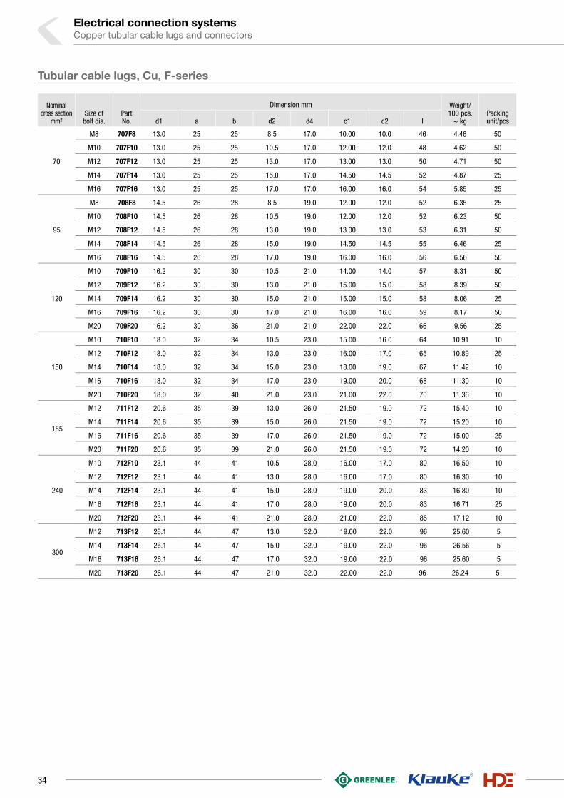
70
M8 707F8 13.0 25 25 8.5 17.0 10.00 10.0 46 4.46 50
M10 707F10 13.0 25 25 10.5 17.0 12.00 12.0 48 4.62 50
M12 707F12 13.0 25 25 13.0 17.0 13.00 13.0 50 4.71 50
M14 707F14 13.0 25 25 15.0 17.0 14.50 14.5 52 4.87 25
M16 707F16 13.0 25 25 17.0 17.0 16.00 16.0 54 5.85 25
95
M8 708F8 14.5 26 28 8.5 19.0 12.00 12.0 52 6.35 25
M10 708F10 14.5 26 28 10.5 19.0 12.00 12.0 52 6.23 50
M12 708F12 14.5 26 28 13.0 19.0 13.00 13.0 53 6.31 50
M14 708F14 14.5 26 28 15.0 19.0 14.50 14.5 55 6.46 25
M16 708F16 14.5 26 28 17.0 19.0 16.00 16.0 56 6.56 50
120
M10 709F10 16.2 30 30 10.5 21.0 14.00 14.0 57 8.31 50
M12 709F12 16.2 30 30 13.0 21.0 15.00 15.0 58 8.39 50
M14 709F14 16.2 30 30 15.0 21.0 15.00 15.0 58 8.06 25
M16 709F16 16.2 30 30 17.0 21.0 16.00 16.0 59 8.17 50
M20 709F20 16.2 30 36 21.0 21.0 22.00 22.0 66 9.56 25
150
M10 710F10 18.0 32 34 10.5 23.0 15.00 16.0 64 10.91 10
M12 710F12 18.0 32 34 13.0 23.0 16.00 17.0 65 10.89 25
M14 710F14 18.0 32 34 15.0 23.0 18.00 19.0 67 11.42 10
M16 710F16 18.0 32 34 17.0 23.0 19.00 20.0 68 11.30 10
M20 710F20 18.0 32 40 21.0 23.0 21.00 22.0 70 11.36 10
185
M12 711F12 20.6 35 39 13.0 26.0 21.50 19.0 72 15.40 10
M14 711F14 20.6 35 39 15.0 26.0 21.50 19.0 72 15.20 10
M16 711F16 20.6 35 39 17.0 26.0 21.50 19.0 72 15.00 25
M20 711F20 20.6 35 39 21.0 26.0 21.50 19.0 72 14.20 10
240
M10 712F10 23.1 44 41 10.5 28.0 16.00 17.0 80 16.50 10
M12 712F12 23.1 44 41 13.0 28.0 16.00 17.0 80 16.30 10
M14 712F14 23.1 44 41 15.0 28.0 19.00 20.0 83 16.80 10
M16 712F16 23.1 44 41 17.0 28.0 19.00 20.0 83 16.71 25
M20 712F20 23.1 44 41 21.0 28.0 21.00 22.0 85 17.12 10
300
M12 713F12 26.1 44 47 13.0 32.0 19.00 22.0 96 25.60 5
M14 713F14 26.1 44 47 15.0 32.0 19.00 22.0 96 26.56 5
M16 713F16 26.1 44 47 17.0 32.0 19.00 22.0 96 25.60 5
M20 713F20 26.1 44 47 21.0 32.0 22.00 22.0 96 26.24 5
Tubular cable lugs, Cu, F-series
34
Nominal cross
section mm²Size of bolt dia.
Part No.
Dimension mm Weight/ 100 pcs.
~ kgPacking unit/pcsd1 a b d2 d4 c1 l3
10
M5 742F5 5.5 14 12 5.3 8.0 6.25 7.5 0.80 50
M6 742F6 5.5 14 12 6.5 8.0 6.25 7.5 0.78 50
M8 742F8 5.5 14 16 8.5 8.0 9.00 9.5 0.84 50
M10 742F10 5.5 14 16 10.5 8.0 10.50 12.0 0.88 50
M12 742F12 5.5 14 19 13.0 8.0 12.00 13.0 0.90 50
16
M5 743F5 6.6 15 13 5.3 9.5 6.25 7.5 1.12 50
M6 743F6 6.6 15 13 6.5 9.5 6.25 7.5 1.12 50
M8 743F8 6.6 15 16 8.5 9.5 10.00 10.0 1.30 50
M10 743F10 6.6 15 17 10.5 9.5 12.00 12.0 1.38 50
M12 743F12 6.6 15 19 13.0 9.5 13.00 13.0 1.34 50
25
M5 744F5 7.9 17 15 5.3 11.0 7.50 7.5 1.52 25
M6 744F6 7.9 17 15 6.5 11.0 7.50 7.5 1.54 25
M8 744F8 7.9 17 17 8.5 11.0 10.00 10.0 1.80 25
M10 744F10 7.9 17 17 10.5 11.0 12.00 12.0 1.79 25
M12 744F12 7.9 17 19 13.0 11.0 13.00 13.0 1.76 25
35
M6 745F6 9.2 19 17 6.5 12.5 7.50 7.5 2.02 25
M8 745F8 9.2 19 18 8.5 12.5 10.00 10.0 2.18 25
M10 745F10 9.2 19 18 10.5 12.5 12.00 12.0 2.30 25
M12 745F12 9.2 19 19 13.0 12.5 13.00 13.0 2.26 25
M14 745F14 9.2 19 21 15.0 12.5 14.50 14.5 2.65 25
50
M6 746F6 11.0 21 21 6.5 15.0 10.00 10.0 3.75 25
M8 746F8 11.0 21 21 8.5 15.0 10.00 10.0 3.57 25
M10 746F10 11.0 21 21 10.5 15.0 12.00 12.0 3.83 25
M12 746F12 11.0 21 21 13.0 15.0 13.00 13.0 3.74 25
M14 746F14 11.0 21 23 15.0 15.0 14.50 14.5 4.20 25
M16 746F16 11.0 21 28 17.0 15.0 16.00 16.0 4.35 25
See next page
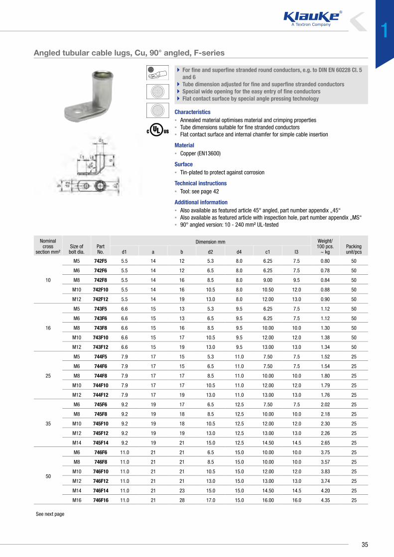
Angled tubular cable lugs, Cu, 90° angled, F-series
` For fine and superfine stranded round conductors, e.g. to DIN EN 60228 Cl. 5 and 6
` Tube dimension adjusted for fine and superfine stranded conductors` Special wide opening for the easy entry of fine conductors` Flat contact surface by special angle pressing technology
Characteristics▪ Annealed material optimises material and crimping properties▪ Tube dimensions suitable for fine stranded conductors▪ Flat contact surface and internal chamfer for simple cable insertion
Material▪ Copper (EN13600)
Surface▪ Tin-plated to protect against corrosion
Technical instructions▪ Tool: see page 42
Additional information▪ Also available as featured article 45° angled, part number appendix „45“▪ Also available as featured article with inspection hole, part number appendix „MS“▪ 90° angled version: 10 - 240 mm² UL-tested
35
1

Electrical connection systemsCopper tubular cable lugs and connectors
Nominal cross
section mm²Size of bolt dia.
Part No.
Dimension mm Weight/ 100 pcs.
~ kgPacking unit/pcsd1 a b d2 d4 c1 l3
70
M8 747F8 13.0 25 25 8.5 17.0 10.00 10.0 4.83 25
M10 747F10 13.0 25 25 11.0 17.0 12.00 12.0 5.18 25
M12 747F12 13.0 25 25 13.0 17.0 13.00 13.0 5.16 25
M14 747F14 13.0 25 25 15.0 17.0 14.50 14.5 5.38 25
M16 747F16 13.0 25 25 17.0 17.0 16.00 16.0 6.50 25
95
M8 748F8 14.5 26 28 8.5 19.0 12.00 12.0 6.66 25
M10 748F10 14.5 26 28 11.0 19.0 12.00 12.0 6.04 25
M12 748F12 14.5 26 28 13.0 19.0 13.00 13.0 6.58 25
M14 748F14 14.5 26 28 15.0 19.0 14.50 14.5 7.24 25
M16 748F16 14.5 26 28 17.0 19.0 16.00 16.0 7.34 25
120
M10 749F10 16.2 30 30 11.0 21.0 14.00 14.0 8.76 10
M12 749F12 16.2 30 30 13.0 21.0 15.00 15.0 8.76 10
M14 749F14 16.2 30 30 15.0 21.0 15.00 15.0 9.15 10
M16 749F16 16.2 30 30 17.0 21.0 16.00 16.0 8.54 10
M20 749F20 16.2 30 36 21.0 21.0 22.00 22.0 9.60 10
150
M10 750F10 18.0 32 34 11.0 23.0 15.00 16.0 11.54 10
M12 750F12 18.0 32 34 13.0 23.0 16.00 18.0 11.58 10
M14 750F14 18.0 32 34 15.0 23.0 18.00 19.0 11.90 10
M16 750F16 18.0 32 34 17.0 23.0 19.00 20.0 11.80 10
M20 750F20 18.0 32 40 21.0 23.0 21.00 22.0 12.00 10
185
M12 751F12 20.6 35 39 13.0 26.0 21.50 19.0 16.36 10
M14 751F14 20.6 35 39 15.0 26.0 21.50 19.0 16.20 10
M16 751F16 20.6 35 39 17.0 26.0 21.50 19.0 15.36 10
M20 751F20 20.6 35 39 21.0 26.0 21.50 19.0 15.80 10
240 M16 752F16 23.1 44 41 17.0 28.0 19.00 20.0 17.80 5
Angled tubular cable lugs, Cu, 90° angled, F-series
36

Nominal cross section mm²
Part No.
Dimension mm Weight/ 100 pcs.
~ kg Packing unit/pcsd1 d4 l
10 722F 5.5 8.0 38 0.90 100
16 723F 6.6 9.5 38 1.25 100
25 724F 7.9 11.0 38 1.56 50
35 725F 9.2 12.5 45 2.19 50
50 726F 11.0 15.0 45 3.37 50
70 727F 13.0 17.0 54 4.65 50
95 728F 14.5 19.0 56 6.05 25
120 729F 16.2 21.0 60 7.58 25
150 730F 18.0 23.0 68 9.83 10
185 731F 20.6 26.0 75 13.30 10
Butt connectors, Cu, F-series
` For fine and superfine stranded round conductors, e.g. to DIN EN 60228 Cl. 5 and 6
` Pipe dimension adjusted for fine and superfine stranded conductors` Special wide opening for the easy entry of fine conductors
Characteristics▪ Simple and safe processing due to butt mark▪ Annealed material optimises material and crimping properties▪ Simple cable entry due to internal chamfer
Material▪ Copper (EN13600)
Surface▪ Tin-plated to protect against corrosion
Technical instructions▪ Tool: see page 42
37
1

Tool type
Crimping range corresponds to nominal cross-section mm²
Crimping Tool Catalogue page
Crimp profilePart No.Crimping head / adapter Crimping Tool Crimping die
See next page
Tool application chart
Tubular cable lugs, butt connectors, parallel connectors and T-connectors „standard type“ and tubular cable lugs for switchgear connections made from CuPart 1 of 2
Electrical connection systemsCopper tubular cable lugs and connectors
Mechanical crimping tools
0.75-16 K2 229
1-4 K511 239
6-50 K5 231
K05 235
6+10 K512 239
10-25 K04 234
10-120 K06 236
16-95 K95 230
TK95 231
25-150 K09 238
50-120 K6 232
120-240 K7 233
185-400 K07 232
Mechanical, electrical, pneumatic crimping tools with interchangeable dies / heads
0.75-2.5 KP1 +KP232 240
KP1L +KP232 240
0.75-10 K50 244 326
EK50ML 254 326
4-10 KP1 +KP242 240
KP1L +KP242 240
6-150 K354 246 328
6-185 K18 248 337
6-300 K22 250 341
Hand hydraulic crimping tools
6-185 HK6018 292 337
HK60UNV +UA18 473 337
6-300 HK6022 294 341
HK60UNV +UA22 473 341
10-240 HK60VP 296
16-300 HK60VPFT 297
16-400 HK12030 298 347
HK12042 300 347
HK120U 302 347
Battery powered crimping tools
0.75-2.5 EKP1ML +KP232 260
0.75-10 EK1550ML 258 326
4-10 EKP1ML +KP242 260
6-150 EK354ML 262 328
EK354 266 328
6-185 EK5018 270 337
EK60UNV +UA18 476 337
EKM60UNV +UA18 475 337
6-240 EK505 268 333
38

Tool type
Crimping range corresponds to nominal cross-section mm²
Crimping Tool Catalogue page
Crimp profilePart No.Crimping head / adapter Crimping Tool Crimping die
Tool application chart
Tubular cable lugs, butt connectors, parallel connectors and T-connectors „standard type“ and tubular cable lugs for switchgear connections made from CuPart 2 of 2
Battery powered crimping tools
6-300 EK6022 274 341
EKM6022 272 341
EK60UNV +UA22 476 341
EKM60UNV +UA22 475 341
10-240 EK60VP 276
EKM60ID 278
16-300 EK60VPFT 277
16-400 EK12032 280 347
EK12042 282 347
EK120U 284 347
EK135FT +UA12T 286 347
EK120UNV +UA15T 477 347
35-500 EK120ID 279
500-630 EK135FT 286 352
Hydraulic crimping systems
6-185 THK18 306 337
6-300 THK22 308 341
16-400 HK122EL380 322 347
HK252 320 353
HK252EL380 322 353
Hydraulic crimping heads
6-185 PK18 306 337
PK60UNV +UA18 474 337
6-300 PK22 308 341
PK60UNV +UA22 474 341
10-240 PK60VP 310
PK60ID 311
16-300 PK60VPFT 310
16-400 PK12042 312 347
PK120U 314 347
PK252 316 353
39
1

Electrical connection systemsCopper tubular cable lugs and connectors
Tool application chart
Insulated tubular cable lugs and butt connectors „standard type“
Tool type
Crimping range corresponds to nominal cross-section mm²
Crimping Tool Catalogue page
Crimp profilePart No.Crimping head / adapter Crimping Tool Crimping die
Mechanical, electrical, pneumatic crimping tools with interchangeable dies / heads
10-70 K354 246 328
10-95 K18 248 337
10-150 K22 250 341
Hand hydraulic crimping tools
10-95 HK6018 292 337
HK60UNV +UA18 473 337
10-150 HK6022 294 341
HK60UNV +UA22 473 341
HK12030 298 347
HK12042 300 347
HK120U 302 347
Battery powered crimping tools
10-70 EK354ML 262 328
EK354 266 328
10-95 EK5018 270 337
EK505 268 333
EK60UNV +UA18 476 337
EKM60UNV +UA18 475 337
10-150 EK6022 274 341
EKM6022 272 341
EK60UNV +UA22 476 341
EKM60UNV +UA22 475 341
EK12032 280 347
EK12042 282 347
EK120U 284 347
EK135FT +UA15T 286 347
EK120UNV +UA12T 477 347
Hydraulic crimping systems
10-95 THK18 306 337
10-150 THK22 308 341
HK122EL380 322 347
HK252EL380 323 353
HK252 320 353
Hydraulic crimping heads
10-95 PK18 306 337
PK60UNV +UA18 474 337
10-150 PK22 308 341
PK60UNV +UA22 474 341
PK12042 312 347
PK120U 314 347
PK252 316 353
40

blue connection
Mechanical crimping tools
6-50 K05BC 234
6-300 K22 250 342
10-120 K06BC 236
25-150 K09BC 237
Mechanical, electrical, pneumatic crimping tools with interchangeable dies / heads
6-150 K354 246 329
Hand hydraulic crimping tools
6-240 HK60UNV +UA5 473 333
6-300 HK6022 294 342
HK60UNV +UA22 473 342
Battery powered crimping tools
6-150 EK354ML 262 329
EK354 266 329
6-240 EK505 268 333
EKM60UNV +UA5 475 333
EK60UNV +UA5 475 333
6-300 EK6022 274 342
EKM6022 272 342
EKM60UNV +UA22 475 342
EK60UNV +UA22 476 342
Hydraulic crimping systems
6-300 THK22 308 342
16-400 HK122EL380 322
Hydraulic crimping heads
6-300 PK22 308 342
PK60UNV +UA22 474 342
Tool application chart
Tubular cable lugs and butt connectors blue connection©
Tool type
Crimping range corresponds to nominal cross-section mm²
Crimping Tool Catalogue page
Crimp profilePart No.Crimping head / adapter Crimping Tool Crimping die
41
1

Electrical connection systemsCopper tubular cable lugs and connectors
Mechanical crimping tools
6-50 K5 231
16-95 K95 230
TK95 231
50-120 K6 232
120-240 K7 233
185-400 K07 232
Mechanical, electrical, pneumatic crimping tools with interchangeable dies / heads
10-35 K354 246 329
10-50 K18 248 337
10-70 K22 250 342
Hand hydraulic crimping tools
10-50 HK6018 292 337
HK60UNV +UA18 473 337
10-70 HK6022 294 342
HK60UNV +UA22 473 342
10-240 HK60VP 296
16-150 HK12030 298 348
HK12042 300 348
HK120U 302 348
16-300 HK60VPFT 297
Battery powered crimping tools
10-35 EK354ML 262 329
EK354 266 329
10-50 EK505 268 334
EK5018 270 337
EK60UNV +UA18 476 337
EKM60UNV +UA18 475 337
10-70 EK6022 274 342
EKM6022 272 342
EK60UNV +UA22 476 342
EKM60UNV +UA22 475 342
10-240 EK60VP 276
EKM60ID 278
16-150 EK12032 280 348
EK12042 282 348
EK120U 284 348
EK135FT +UA15T 286 348
EK120UNV +UA12T 322 348
16-300 EK60VPFT 277
35-500 EK120ID 279
Hydraulic crimping systems
10-50 THK18 306 337
10-70 THK22 308 342
16-300 HK252 320 354
HK252EL380 323 354
See next page
Tool application chart
Tubular cable lugs and butt connectors for fine stranded conductors Part 1 of 2
Tool type
Crimping range corresponds to nominal cross-section mm²
Crimping Tool Catalogue page
Crimp profilePart No.Crimping head / adapter Crimping Tool Crimping die
42

Hydraulic crimping heads
10-50 PK18 306 337
PK60UNV +UA18 474 337
10-70 PK22 308 342
PK60UNV +UA22 474 342
10-240 PK60VP 310
PK60ID 311
16-150 PK12042 312 348
PK120U 314 348
16-300 PK60VPFT 310
PK252 316 354
Tool application chart
Tubular cable lugs and butt connectors for fine stranded conductors Part 2 of 2
Tool type
Crimping range corresponds to nominal cross-section mm²
Crimping Tool Catalogue page
Crimp profilePart No.Crimping head / adapter Crimping Tool Crimping die
43
1

Electrical connection systemsCopper tubular cable lugs and connectors
Mechanical crimping tools
0.75-16 K02 229
1.5-4 K93 228
6-10 K94 228
25-50* K05 235
Mechanical, electrical, pneumatic crimping tools with interchangeable dies / heads
1.5-10 K50 244 326
EK50ML 254 326
1.5-16 K354 246 329
K18 248 338
K22 250 342
Hand hydraulic crimping tools
1.5-16 HK6018 292 338
HK60UNV +UA18 473 338
HK6022 294 342
HK60UNV +UA22 473 342
Battery powered crimping tools
1.5-10 EK1550ML 258 326
1.5-16 EK354ML 262 329
EK354 266 329
EK5018 270 338
EK60UNV +UA18 476 338
EKM60UNV +UA18 475 338
EK6022 274 342
EKM6022 272 342
EK60UNV +UA22 476 342
EKM60UNV +UA22 475 342
Hydraulic crimping systems
1.5-16 THK18 306 338
THK22 308 342
Hydraulic crimping heads
1.5-16 PK18 306 338
PK60UNV +UA18 474 338
PK22 308 342
PK60UNV +UA22 474 342
*For cross-sections 25 + 35 mm2 use the die size 25 mm2. For cross-section 50 mm2 use the die size 35 mm². We recommend 2 crimps on each side
Tool application chart
Tubular cable lugs and butt connectors for solid conductors
Tool type
Crimping range corresponds to nominal cross-section mm²
Crimping Tool Catalogue page
Crimp profilePart No.Crimping head / adapter Crimping Tool Crimping die
44

45
1

THE RESISTANT – TUBULAR CABLE LUGS AND CONNECTORS, NICKEL OR STAINLESS STEELWe also develop for use in tough conditions. Our tubular cable lugs and connectors
made from nickel and stainless steel are a cut above: withstanding temperatures of up
to 650 °C, our Klauke products have without doubt developed to meet the requirements
of the chemical industry, the foodstuff sector and foodstuff industry. You can also rely
on our high-quality products for special applications. We know what we are doing.
In brief
`` Tough to 650 °C
`` Suitable for the chemical and foodstuff industry sectors, for instance
`` Suitable even for aggressive environments, such as contact with salt water
Tubular cable lugs and connectors, nickel or stainless steelElectrical connection systems
46

` Safe in aggressive environments with stainless steel
High-quality stainless steel ensures extra resilience, especially
in aggressive environments. The resistance is retained.
◾ High-quality V2A and V4A stainless steel
◾ Acid resistant
◾ Can be used at temperatures to 400 °C
◾ V2A stainless steel for the chemical and foodstuff sectors
and salt water applications
◾ V4A stainless steel in chlorinated environments
such as swimming pools, for instance
` When things get hot: Nickel cable lugs
Nickel cable lugs are especially suitable for use in applications
at high temperatures of up to 650 °C. Thanks to their high
resilience they no longer need to be frequently replaced at
connections exposed to heat.
◾ High-quality nickel
◾ Heat-resistant to 650 °C
◾ No constant replacement of the cable lug at hot locations
47
1

Nominal cross section
mm²Size of
bolt dia.Part No.
Dimension mm Weight/ 100 pcs.
~ kgPacking unit/
pcsd1 a b d2 d4 l
0.5-1M4 79V4 1.6 6 6.5 4.3 3.2 13 0.080 100
M5 79V5 1.6 6 7.5 5.3 3.2 14 0.080 100
1.5-2.5
M4 80V4 3.0 8 9.0 4.3 5.0 17 0.260 100
M5 80V5 3.0 8 9.0 5.5 5.0 17 0.190 100
M6 80V6 3.0 8 9.5 6.5 5.0 19 0.215 100
4-6
M4 81V4 4.0 9 9.0 4.3 6.0 18 0.260 100
M5 81V5 4.0 9 9.5 5.5 6.0 19 0.280 100
M6 81V6 4.0 9 10.0 6.5 6.0 19 0.280 100
10
M5 82V5 5.0 10 12.5 5.5 8.0 22 0.710 100
M6 82V6 5.0 10 12.5 6.5 8.0 22 0.780 100
M8 82V8 5.0 10 15.0 8.5 8.0 25 0.780 100
16
M5 83V5 6.0 13 12.0 5.5 8.0 28 0.500 50
M6 83V6 6.0 13 12.0 6.5 8.0 28 0.550 50
M8 83V8 6.0 13 15.0 8.5 8.0 29 0.600 50
25M6 84V6 7.0 15 14.0 6.5 10.0 30 1.210 50
M8 84V8 7.0 15 16.0 8.5 10.0 32 1.850 50
35M6 85V6 9.0 17 17.0 6.5 12.0 32 1.600 50
M8 85V8 9.0 17 17.0 8.5 12.0 35 1.850 50
50
M6 86V6 10.0 19 20.0 6.5 14.0 37 2.800 50
M8 86V8 10.0 19 20.0 8.5 14.0 37 2.600 50
M10 86V10 10.0 19 20.0 10.5 14.0 39 2.800 50
M12 86V12 10.0 19 20.0 13.0 14.0 43 2.960 50
70
M8 87V8 12.0 21 23.0 8.5 16.0 43 3.650 25
M10 87V10 12.0 21 23.0 10.5 16.0 44 3.930 25
M12 87V12 12.0 21 23.0 13.0 16.0 46 3.850 25
M16 87V16 12.0 21 26.0 17.0 16.0 46 3.960 25
95
M8 88V8 14.0 25 26.0 8.5 18.0 48 4.650 25
M10 88V10 14.0 25 26.0 10.5 18.0 48 5.610 25
M12 88V12 14.0 25 26.0 13.0 18.0 49 5.540 25
Tubular cable lugs and connectors, nickel or stainless steelElectrical connection systems
Tubular cable lugs, stainless steel
` For multi-stranded round conductors, e.g. to DIN EN 60228 Cl. 2` For pre-rounded stranded sector shaped conductors` Ideal for aggressive environmental conditions, acid and rust-resistant` Heat resistant up to 400 °C
Characteristics▪ Flat contact surface by special pressing technology▪ Simple and safe connection due to flat contact surfaces and internal chamfer
Material▪ V2A
Technical instructions▪ Tool: see page 53
Additional information▪ Also available as featured article in stainless steel V4A
48

Nominal cross section mm²
Part No.
Dimension mm Weight/ 100 pcs.
~ kg Packing unit/pcsd1 d4 l
0.5-1 79R 1.6 3.2 25 0.135 50
1.5-2.5 80R 3.0 5.0 25 0.250 50
4-6 81R 4.0 6.0 25 0.325 50
10 82R 5.0 8.0 25 0.360 50
16 83R 6.0 8.0 30 0.510 50
25 84R 7.0 10.0 35 1.100 25
35 85R 9.0 12.0 40 1.560 25
50 86R 10.0 14.0 45 2.670 25
70 87R 12.0 16.0 50 3.400 25
95 88R 14.0 18.0 55 4.300 25
Butt connectors, stainless steel
` For multi-stranded round conductors, e.g. to DIN EN 60228 Cl. 2` Ideal for aggressive environmental conditions, acid and rust-resistant` Heat resistant up to 400 °C
Characteristics▪ Simple and safe processing due to butt mark▪ Simple cable entry due to internal chamfer
Material▪ V2A
Technical instructions▪ Tool: see page 53
Additional information▪ Also available as featured article in stainless steel V4A
49
1

Nominal cross section
mm²Size of
bolt dia.Part No.
Dimension mm Weight/ 100 pcs.
~ kgPacking unit/
pcsd1 a b d2 d4 l
0.5-1M4 56N4 1.6 6 6.5 4.3 3.2 13 0.080 100
M5 56N5 1.6 6 7.5 5.3 3.2 14 0.080 100
1.5-2.5
M4 57N4 2.3 6 7.0 4.3 3.9 13 0.105 100
M5 57N5 2.3 6 7.5 5.3 3.9 14 0.105 100
M6 57N6 2.3 6 9.5 6.5 3.9 16 0.130 100
4-6
M4 58N4 3.6 9 9.5 4.3 5.6 18 0.275 100
M5 58N5 3.6 9 9.5 5.3 5.6 19 0.275 100
M6 58N6 3.6 9 9.5 6.5 5.6 19 0.260 100
10M5 59N5 4.5 10 12.0 5.5 6.5 21 0.340 100
M6 59N6 4.5 10 12.0 6.5 6.5 22 0.360 100
16
M5 60N5 5.5 13 12.0 5.5 7.5 26 0.470 100
M6 60N6 5.5 13 12.0 6.5 7.5 27 0.480 100
M8 60N8 5.5 13 13.5 8.5 7.5 29 0.560 100
25M6 61N6 7.0 15 14.0 6.5 10.0 30 1.200 50
M8 61N8 7.0 15 16.0 8.5 10.0 32 1.320 50
35M6 62N6 8.5 17 17.0 6.5 12.0 32 1.850 50
M862N8 8.5 17 17.0 8.5 12.0 34 2.000 50
5063N8 10.0 19 20.0 8.5 14.0 37 2.900 50
M1063N10 10.0 19 20.0 10.5 14.0 39 3.100 50
7064N10 12.0 21 23.0 10.5 16.5 44 4.600 25
M12 64N12 12.0 21 23.0 13.0 16.5 46 4.660 25
95M10 65N10 13.5 25 26.0 10.5 18.0 48 5.550 25
M12 65N12 13.5 25 26.0 13.0 18.0 49 5.600 25
Tubular cable lugs and connectors, nickel or stainless steelElectrical connection systems
Tubular cable lug, Ni
` For multi-stranded round conductors, e.g. to DIN EN 60228 Cl. 2` Suitable for high temperatures up to 650 °C
Characteristics▪ Simple and safe connection due to flat contact surfaces and internal chamfer
Material▪ High-grade nickel
Technical instructions▪ Tool: see page 53
50

Nominal cross section
mm²Size of
bolt dia.Part No.
Dimension mm Weight/ 100 pcs.
~ kgPacking unit/
pcsd1 a b d2 d4 l
0.5-1M4 56C4 1.6 6 6.5 4.3 3.2 13 0.070 50
M5 56C5 1.6 6 7.5 5.3 3.2 14 0.075 50
1.5-2.5
M4 57C4 2.3 6 7.0 4.3 3.9 13 0.095 50
M5 57C5 2.3 6 7.5 5.3 3.9 14 0.095 50
M6 57C6 2.3 6 9.5 6.5 3.9 16 0.110 50
4-6
M4 58C4 3.6 9 9.5 4.3 5.6 18 0.250 50
M5 58C5 3.6 9 9.5 5.3 5.6 19 0.255 50
M6 58C6 3.6 9 9.5 6.5 5.6 19 0.235 50
10M5 59C5 4.5 10 12.0 5.5 6.5 21 0.320 50
M6 59C6 4.5 10 12.0 6.5 6.5 22 0.340 50
16
M5 60C5 5.5 13 12.0 5.5 7.5 26 0.440 50
M6 60C6 5.5 13 12.0 6.5 7.5 27 0.450 50
M8 60C8 5.5 13 13.5 8.5 7.5 29 0.520 50
Tubular cable lugs, Cu, fork type
` For multi-stranded round conductors, e.g. to DIN EN 60228 Cl. 2` Suitable for high temperatures up to 650 °C` Simple fork-type mounting
Characteristics▪ Simple and safe connection due to flat contact surfaces and internal chamfer
Material▪ High-grade nickel
Technical instructions▪ Tool: see page 53
51
1

Nominal cross section mm²
Part No.
Dimension mm Weight/ 100 pcs.
~ kg Packing unit/pcsd1 d4 l
0.5-1 62R 1.6 3.2 25 0.135 50
1.5-2.5 63R 2.3 3.9 25 0.170 50
4-6 64R 3.6 5.6 25 0.325 50
10 65R 4.5 6.5 25 0.360 50
16 66R 5.5 7.5 30 0.510 50
Tubular cable lugs and connectors, nickel or stainless steelElectrical connection systems
Butt connectors, Ni
` For multi-stranded round conductors, e.g. to DIN EN 60228 Cl. 2` Suitable for high temperatures to 650 °C
Characteristics▪ Simple and safe processing due to butt mark▪ Simple cable entry due to internal chamfer
Material▪ High-grade nickel
Technical instructions▪ Tool: see page 53
52

Tool application chart
Tubular cable lugs and butt connectors made from stainless steel or nickel
Mechanical crimping tools 0.5-6 K25 230
Mechanical, electrical, pneumatic crimping tools with interchangeable dies / heads
0.5-16 K354 246 329
10-50 K22 250 342
Hand hydraulic crimping tools
10-50 HK6022 294 342
HK6022 +UA22 473 342
70-95 HK12030 298 348
HK12042 300 348
HK120U 302 348
Battery powered crimping tools
0.5-16 EK354ML 262 329
EK354 266 342
10-50 EKM6022 272 342
EK6022 274 342
EK60UNV +UA22 476 342
EKM60UNV +UA22 475 342
70-95 EK12032 280 348
EK12042 282 348
EK120U 284 348
EK120UNV +UA12T 477 348
EK135FT +UA15T 286 348
Hydraulic crimping systems
10-50 THK22 308 342
Hydraulic crimping heads
10-50 PK22 308 342
PK60UNV +UA22 474 342
70-95 PK12042 312 348
PK120U 314 348
Tool type
Crimping range corresponds to nominal cross-section mm²
Crimping Tool Catalogue page
Crimp profilePart No.Crimping head / adapter Crimping Tool Crimping die
53
1
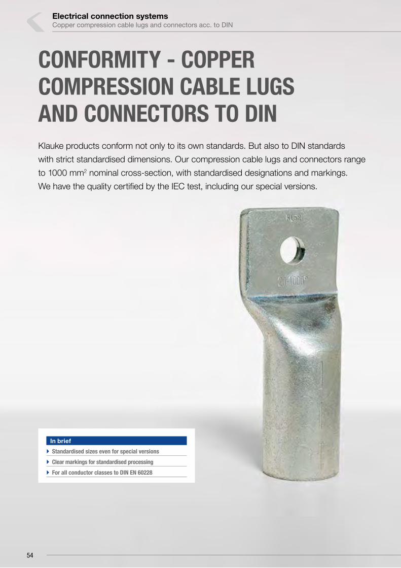
Electrical connection systems
CONFORMITY - COPPER COMPRESSION CABLE LUGS AND CONNECTORS TO DINKlauke products conform not only to its own standards. But also to DIN standards
with strict standardised dimensions. Our compression cable lugs and connectors range
to 1000 mm2 nominal cross-section, with standardised designations and markings.
We have the quality certified by the IEC test, including our special versions.
In brief
`` Standardised sizes even for special versions
`` Clear markings for standardised processing
`` For all conductor classes to DIN EN 60228
Copper compression cable lugs and connectors acc. to DIN
54

` Tested and certified for safety
Our DIN cable lugs and connectors are strictly manufactured
to standard. In addition, the test suggested in the standard
has been passed with ease.
◾ Simple processing with DIN system
◾ Safety through standardised tests
◾ For all conductor classes to DIN EN 60228 and
copper wires to DIN 46267-1
` Every version standardised
We offer cable lugs with tube dimension to DIN in numerous
different forms and versions. If there happens to be no suitable
connector for you, we will of course make you one to suit your
needs.
◾ Flexible thanks to numerous versions
◾ Various surfaces available
◾ Many special versions based on the DIN standard available
◾ Manufactured to suit your particular requirements
` Clear markings
Where simplicity and safety are key: Every cable lug to DIN
comes with the appropriate crimping instruction. Readily
visible markings indicate the crimping location required to
work in compliance with the standard. Code numbers on the
dies and cable lugs show the correct crimp at a glance.
Code
Manufacturer’s mark
hole diameter
Wide crimp
Cross-section
Narrow crimp
55
1

Nominal cross
section mm²
Size of bolt
diameter Part No. Hint Code
Dimension mm Weight/ 100 pcs.
~ kgPacking unit/pcsa b d1 d2 d4 c1 c2 l
6
M 5 101R5 5 10 8.5 3.8 5.3 5.5 6.5 7.5 24 0.24 100
M 6 101R6 5 10 8.5 3.8 6.4 5.5 7.5 8.0 24 0.30 100
M 8 101R8 * 5 10 13.0 3.8 8.4 5.5 10.0 10.0 24 0.34 100
10
M 5 102R5 6 10 9.0 4.5 5.3 6.0 7.0 8.5 27 0.37 100
M 6 102R6 6 10 9.0 4.5 6.4 6.0 7.5 8.5 27 0.36 100
M 8 102R8 * 6 10 13.0 4.5 8.4 6.0 10.0 10.0 27 0.38 100
16
M 6 103R6 8 20 13.0 5.5 6.4 8.5 7.5 8.0 36 1.19 100
M 8 103R8 8 20 13.0 5.5 8.4 8.5 10.0 10.0 36 1.22 100
M 10 103R10 8 20 17.0 5.5 10.5 8.5 12.0 12.0 36 1.30 100
M 12 103R12 * 8 20 18.0 5.5 13.0 8.5 13.0 13.0 36 1.27 100
25
M 6 104R6 10 20 14.0 7.0 6.4 10.0 7.5 8.0 38 1.51 50
M 8 104R8 10 20 16.0 7.0 8.4 10.0 10.0 10.0 38 1.54 50
M 10 104R10 10 20 17.0 7.0 10.5 10.0 12.0 12.0 38 1.62 50
M 12 104R12 10 20 19.0 7.0 13.0 10.0 13.0 13.0 38 1.66 25
35
M 6 105R6 * 12 20 17.0 8.2 6.4 12.5 7.5 8.0 42 2.77 50
M 8 105R8 12 20 17.0 8.2 8.4 12.5 10.0 10.0 42 2.85 50
M 10 105R10 12 20 19.0 8.2 10.5 12.5 12.0 12.0 42 2.84 50
M 12 105R12 12 20 21.0 8.2 13.0 12.5 13.0 13.0 42 2.79 50
M 14 105R14 * 12 20 21.0 8.2 15.0 12.5 14.5 14.5 42 2.70 25
see next page
Electrical connection systemsCopper compression cable lugs and connectors acc. to DIN
Compression cable lugs to DIN, Cu
` For round conductors, e.g. to DIN EN 60228 Cl. 1, 2, 5 and 6` For non-tension copper cables, e.g. to DIN 48201` For pre-rounded multi-stranded sector shaped conductors` With code number for clear tool assignment` To DIN 46235
Characteristics▪ Easy to process due to crimp markings▪ Annealed material optimises material and crimping properties▪ Simple and safe connection due to flat contact surfaces and internal chamfer
Material▪ Copper (EN13600)
Surface▪ Tin-plated to protect against corrosion
Technical instructions▪ Tool: see page 69▪ Sleeves for compacted conductors and sleeves for 3-core and 4-core cables, see
chapter „Sleeves for compacted conductors and sector shaped conductors - Cu“
Additional information▪ Part Number appendix for bright version „BK“▪ Item in barrier sealed design upon request▪ 10 - 800 mm² IEC-tested▪ * = not standardised
56

Nominal cross
section mm²
Size of bolt
diameter Part No. Hint Code
Dimension mm Weight/ 100 pcs.
~ kgPacking unit/pcsa b d1 d2 d4 c1 c2 l
50
M 8 106R8 14 28 20.0 10.0 8.4 14.5 10.0 10.0 52 4.46 50
M 10 106R10 14 28 22.0 10.0 10.5 14.5 12.0 12.0 52 4.48 50
M 12 106R12 14 28 24.0 10.0 13.0 14.5 13.0 13.0 52 4.40 50
M 14 106R14 * 14 28 24.0 10.0 15.0 14.5 14.5 14.5 52 4.30 25
M 16 106R16 14 28 28.0 10.0 17.0 14.5 16.0 16.0 52 4.57 25
70
M 8 107R8 16 28 24.0 11.5 8.4 16.5 10.0 10.0 55 5.92 50
M 10 107R10 16 28 24.0 11.5 10.5 16.5 12.0 12.0 55 6.02 50
M 12 107R12 16 28 24.0 11.5 13.0 16.5 13.0 13.0 55 5.89 50
M 14 107R14 * 16 28 24.0 11.5 15.0 16.5 14.5 14.5 55 5.80 25
M 16 107R16 16 28 30.0 11.5 17.0 16.5 16.0 16.0 55 6.13 25
95
M 8 108R8 * 18 35 28.0 13.5 8.4 19.0 12.0 12.0 65 9.21 25
M 10 108R10 18 35 28.0 13.5 10.5 19.0 12.0 12.0 65 8.97 50
M 12 108R12 18 35 28.0 13.5 13.0 19.0 13.0 13.0 65 8.62 50
M 14 108R14 * 18 35 28.0 13.5 15.0 19.0 14.5 14.5 65 8.78 25
M 16 108R16 18 35 32.0 13.5 17.0 19.0 16.0 16.0 65 9.00 50
120
M 10 109R10 20 35 32.0 15.5 10.5 21.0 15.0 16.0 70 11.40 50
M 12 109R12 20 35 32.0 15.5 13.0 21.0 16.0 17.0 70 11.31 50
M 14 109R14 * 20 35 32.0 15.5 15.0 21.0 18.0 19.0 70 11.45 25
M 16 109R16 20 35 32.0 15.5 17.0 21.0 19.0 20.0 70 11.24 50
M 20 109R20 20 35 38.0 15.5 21.0 21.0 21.0 22.0 70 11.03 25
150
M 10 110R10 22 35 34.0 17.0 10.5 23.5 15.0 16.0 78 16.38 10
M 12 110R12 22 35 34.0 17.0 13.0 23.5 16.0 17.0 78 16.29 25
M 14 110R14 * 22 35 34.0 17.0 15.0 23.5 19.0 20.0 78 16.38 10
M 16 110R16 22 35 34.0 17.0 17.0 23.5 19.0 20.0 78 16.17 10
M 20 110R20 22 35 40.0 17.0 21.0 23.5 21.0 22.0 78 15.90 10
185
M 10 111R10 25 40 37.0 19.0 10.5 25.5 15.0 16.0 82 18.96 10
M 12 111R12 25 40 37.0 19.0 13.0 25.5 16.0 17.0 82 18.11 10
M 14 111R14 * 25 40 37.0 19.0 15.0 25.5 19.0 20.0 82 19.21 10
M 16 111R16 25 40 37.0 19.0 17.0 25.5 19.0 20.0 82 18.74 25
M 20 111R20 25 40 40.0 19.0 21.0 25.5 21.0 22.0 82 18.69 10
240
M 12 112R12 28 40 42.0 21.5 13.0 29.0 16.0 17.0 92 27.00 10
M 14 112R14 * 28 40 42.0 21.5 15.0 29.0 19.0 20.0 92 27.58 10
M 16 112R16 28 40 42.0 21.5 17.0 29.0 19.0 20.0 92 27.37 25
M 20 112R20 28 40 45.0 21.5 21.0 29.0 21.0 22.0 92 26.88 10
300
M 14 113R14 * 32 50 46.0 24.5 15.0 32.0 19.0 22.0 100 33.29 5
M 16 113R16 32 50 46.0 24.5 17.0 32.0 19.0 22.0 100 32.94 5
M 20 113R20 32 50 46.0 24.5 21.0 32.0 22.0 22.0 100 33.24 5
400
M 14 114R14 * 38 70 54.0 27.5 15.0 38.5 25.0 25.0 115 69.38 5
M 16 114R16 38 70 54.0 27.5 17.0 38.5 25.0 25.0 115 68.54 5
M 20 114R20 38 70 54.0 27.5 21.0 38.5 25.0 25.0 115 65.40 5
500M 16 115R16 * 42 70 60.0 31.0 17.0 42.0 25.0 25.0 125 83.31 1
M 20 115R20 42 70 60.0 31.0 21.0 42.0 25.0 25.0 125 81.58 1
625M 16 116R16 * 44 80 64.0 34.5 17.0 44.0 25.0 25.0 135 79.60 1
M 20 116R20 44 80 64.0 34.5 21.0 44.0 25.0 25.0 135 79.69 1
800M 16 117R16 * 52 100 75.0 40.0 17.0 52.0 30.0 30.0 165 150.00 1
M 20 117R20 52 100 75.0 40.0 21.0 52.0 30.0 30.0 165 149.00 1
1000M 16 118R16 * 58 100 83.0 44.0 17.0 58.0 30.0 30.0 165 199.00 1
M 20 118R20 58 100 83.0 44.0 21.0 58.0 30.0 30.0 165 195.00 1
Compression cable lugs to DIN, Cu
57
1

Nominal cross section
mm²
Size of bolt
diameter Part No. Code
Dimension mm Weight/ 100 pcs.
~ kgPacking unit/pcsa b d1 d2 d4 c1 l3
6M 5 161R5 5 10 8.5 3.8 5.3 5.5 6.5 9 0.28 50
M 6 161R6 5 10 8.5 3.8 6.4 5.5 7.5 10 0.32 50
10
M 5 162R5 6 10 9.0 4.5 5.3 6.0 7.0 10 0.34 50
M 6 162R6 6 10 9.0 4.5 6.4 6.0 7.5 10 0.35 50
M 8 162R8 6 10 13.0 4.5 8.4 6.0 10.0 13 0.37 50
16
M 6 163R6 8 20 13.0 5.5 6.4 8.5 7.5 11 1.20 50
M 8 163R8 8 20 13.0 5.5 8.4 8.5 10.0 13 1.30 50
M 10 163R10 8 20 17.0 5.5 10.5 8.5 12.0 15 1.40 50
M 12 163R12 8 20 18.0 5.5 13.0 8.5 13.0 18 1.33 50
25
M 6 164R6 10 20 14.0 7.0 6.4 10.0 7.5 11 1.54 25
M 8 164R8 10 20 16.0 7.0 8.4 10.0 10.0 13 1.60 25
M 10 164R10 10 20 17.0 7.0 10.5 10.0 12.0 15 1.63 25
M 12 164R12 10 20 19.0 7.0 13.0 10.0 13.0 18 1.70 25
35
M 8 165R8 12 20 17.0 8.2 8.4 12.5 10.0 13 2.72 25
M 10 165R10 12 20 19.0 8.2 10.5 12.5 12.0 15 2.76 25
M 12 165R12 12 20 21.0 8.2 13.0 12.5 13.0 18 2.85 25
M 14 165R14 12 20 21.0 8.2 15.0 12.5 14.5 20 2.92 25
50
M 8 166R8 14 28 20.0 10.0 8.4 14.5 10.0 16 4.39 25
M 10 166R10 14 28 22.0 10.0 10.5 14.5 12.0 16 4.46 25
M 12 166R12 14 28 24.0 10.0 13.0 14.5 13.0 18 4.49 25
M 14 166R14 14 28 24.0 10.0 15.0 14.5 14.5 20 4.73 25
M 16 166R16 14 28 28.0 10.0 17.0 14.5 16.0 22 4.66 25
see next page
Electrical connection systemsCopper compression cable lugs and connectors acc. to DIN
Angled compression cable lugs, Cu, 90° angled
` For round conductors, e.g. to DIN EN 60228 Cl. 1, 2, 5 and 6` For non-tension copper cables, e.g. to DIN 48201` For pre-rounded multi-stranded sector shaped conductors` Tube dimensions according to DIN 46235` With code number for clear tool assignment
Characteristics▪ Flat contact surface by special angle pressing process▪ Easy to process due to crimp markings▪ Annealed material optimises material and crimping properties▪ Simple cable entry due to internal chamfer
Material▪ Copper (EN13600)
Surface▪ Tin-plated to protect against corrosion
Technical instructions▪ Sleeves for compacted conductors and sleeves for 3-core and 4-core cables, see
chapter „Sleeves for compacted conductors and sector shaped conductors - Cu“▪ Tool: see page 69
Additional information▪ Part Number appendix for bright version „BK“▪ 10 - 240 mm² IEC-tested
58

Nominal cross section
mm²
Size of bolt
diameter Part No. Code
Dimension mm Weight/ 100 pcs.
~ kgPacking unit/pcsa b d1 d2 d4 c1 l3
70
M 8 167R8 16 28 24.0 11.5 8.4 16.5 10.0 14 5.92 25
M 10 167R10 16 28 24.0 11.5 10.5 16.5 12.0 16 6.31 25
M 12 167R12 16 28 24.0 11.5 13.0 16.5 13.0 18 6.34 25
M 14 167R14 16 28 24.0 11.5 15.0 16.5 14.5 20 6.50 25
M 16 167R16 16 28 30.0 11.5 17.0 16.5 16.0 22 6.63 25
95
M 10 168R10 18 35 28.0 13.5 10.5 19.0 12.0 17 9.03 25
M 12 168R12 18 35 28.0 13.5 13.0 19.0 13.0 18 9.27 25
M 14 168R14 18 35 28.0 13.5 15.0 19.0 14.5 20 9.06 25
M 16 168R16 18 35 32.0 13.5 17.0 19.0 16.0 22 9.18 25
120
M 10 169R10 20 35 32.0 15.5 10.5 21.0 15.0 17 10.41 10
M 12 169R12 20 35 32.0 15.5 13.0 21.0 16.0 18 10.65 10
M 14 169R14 20 35 32.0 15.5 15.0 21.0 18.0 20 10.75 10
M 16 169R16 20 35 32.0 15.5 17.0 21.0 19.0 22 10.72 10
M 20 169R20 20 35 38.0 15.5 21.0 21.0 21.0 24 11.00 10
150
M 10 170R10 22 35 34.0 17.0 10.5 23.5 15.0 17 14.18 10
M 12 170R12 22 35 34.0 17.0 13.0 23.5 16.0 18 14.33 10
M 14 170R14 22 35 34.0 17.0 15.0 23.5 19.0 20 15.60 10
M 16 170R16 22 35 34.0 17.0 17.0 23.5 19.0 22 15.24 10
M 20 170R20 22 35 40.0 17.0 21.0 23.5 21.0 24 15.70 10
185
M 10 171R10 25 40 37.0 19.0 10.5 25.5 15.0 22 18.60 10
M 12 171R12 25 40 37.0 19.0 13.0 25.5 16.0 22 18.69 10
M 14 171R14 25 40 37.0 19.0 15.0 25.5 19.0 22 19.10 10
M 16 171R16 25 40 37.0 19.0 17.0 25.5 19.0 22 19.00 10
M 20 171R20 25 40 40.0 19.0 21.0 25.5 21.0 24 18.72 10
240
M 12 172R12 28 40 42.0 21.5 13.0 29.0 16.0 22 25.09 10
M 14 172R14 28 40 42.0 21.5 15.0 29.0 19.0 22 25.70 10
M 16 172R16 28 40 42.0 21.5 17.0 29.0 19.0 22 24.96 10
M 20 172R20 28 40 45.0 21.5 21.0 29.0 21.0 24 25.26 10
Angled compression cable lugs, Cu, 90° angled
59
1

Nominal cross section
mm²
Size of bolt
diameter Part No. Code
Dimension mm Weight/ 100 pcs.
~ kgPacking unit/pcsa b d1 d2 d4 c1 l3
6M 5 161R545 5 10 8.5 3.8 5.5 5.5 6.5 9 0.32 50
M 6 161R645 5 10 8.5 3.8 6.5 5.5 7.5 10 0.34 50
10
M 5 162R545 6 10 9.0 4.5 5.5 6.0 7.0 10 0.36 50
M 6 162R645 6 10 9.0 4.5 6.5 6.0 7.5 10 0.35 50
M 8 162R845 6 10 13.0 4.5 8.5 6.0 10.0 13 0.39 50
16
M 6 163R645 8 20 13.0 5.5 6.5 8.5 7.5 11 1.20 50
M 8 163R845 8 20 13.0 5.5 8.5 8.5 10.0 13 0.28 50
M 10 163R1045 8 20 17.0 5.5 10.5 8.5 12.0 15 1.34 50
M 12 163R1245 8 20 18.0 5.5 13.0 8.5 13.0 18 1.35 50
25
M 6 164R645 10 20 14.0 7.0 6.5 10.0 7.5 11 1.49 25
M 8 164R845 10 20 16.0 7.0 8.5 10.0 10.0 13 1.60 25
M 10 164R1045 10 20 17.0 7.0 10.5 10.0 12.0 15 1.64 25
M 12 164R1245 10 20 19.0 7.0 13.0 10.0 13.0 18 1.73 25
35
M 8 165R845 12 20 17.0 8.2 8.5 12.5 10.0 13 2.72 25
M 10 165R1045 12 20 19.0 8.2 10.5 12.5 12.0 15 2.92 25
M 12 165R1245 12 20 21.0 8.2 13.0 12.5 13.0 18 2.98 25
M 14 165R1445 12 20 21.0 8.2 15.0 12.5 14.5 20 3.03 25
50
M 8 166R845 14 28 20.0 10.0 8.5 14.5 10.0 13 4.63 25
M 10 166R1045 14 28 22.0 10.0 10.5 14.5 12.0 16 4.84 25
M 12 166R1245 14 28 24.0 10.0 13.0 14.5 13.0 18 4.94 25
M 14 166R1445 14 28 24.0 10.0 15.0 14.5 14.5 20 4.96 25
M 16 166R1645 14 28 28.0 10.0 17.0 14.5 16.0 22 4.92 25
see next page
Electrical connection systemsCopper compression cable lugs and connectors acc. to DIN
Angled compression cable lugs, Cu, 45° angled
` For round conductors, e.g. to DIN EN 60228 Cl. 1, 2, 5 and 6` For non-tension copper cables, e.g. to DIN 48201` For pre-rounded multi-stranded sector shaped conductors` Tube dimensions according to DIN 46235` With code number for clear tool assignment
Characteristics▪ Flat contact surface by special angle pressing process▪ Easy to process due to crimp markings▪ Annealed material optimises material and crimping properties▪ Simple cable entry due to internal chamfer
Material▪ Copper (EN13600)
Surface▪ Tin-plated to protect against corrosion
Technical instructions▪ Sleeves for compacted conductors and sleeves for 3-core and 4-core cables, see
chapter „Sleeves for compacted conductors and sector shaped conductors - Cu“▪ Tool: see page 69
Additional information▪ Part Number appendix for bright version „BK“▪ 10 - 240 mm² IEC-tested
60

Nominal cross section
mm²
Size of bolt
diameter Part No. Code
Dimension mm Weight/ 100 pcs.
~ kgPacking unit/pcsa b d1 d2 d4 c1 l3
70
M 8 167R845 16 28 24.0 11.5 8.5 16.5 10.0 14 6.40 25
M 10 167R1045 16 28 24.0 11.5 10.5 16.5 12.0 16 6.76 25
M 12 167R1245 16 28 24.0 11.5 13.0 16.5 13.0 18 6.90 25
M 14 167R1445 16 28 24.0 11.5 15.0 16.5 14.5 20 6.72 25
M 16 167R1645 16 28 30.0 11.5 17.0 16.5 16.0 22 6.96 25
95
M 10 168R1045 18 35 28.0 13.5 10.5 19.0 12.0 17 9.64 25
M 12 168R1245 18 35 28.0 13.5 13.0 19.0 13.0 18 9.21 25
M 14 168R1445 18 35 28.0 13.5 15.0 19.0 14.5 20 9.51 25
M 16 168R1645 18 35 32.0 13.5 17.0 19.0 16.0 22 9.40 25
120
M 10 169R1045 20 35 32.0 15.5 10.5 21.0 15.0 17 11.09 10
M 12 169R1245 20 35 32.0 15.5 13.0 21.0 16.0 18 11.45 10
M 14 169R1445 20 35 32.0 15.5 15.0 21.0 18.0 20 11.55 10
M 16 169R1645 20 35 32.0 15.5 17.0 21.0 19.0 22 11.76 10
M 20 169R2045 20 35 38.0 15.5 21.0 21.0 21.0 24 11.55 10
150
M 10 170R1045 22 35 34.0 17.0 10.5 23.5 15.0 17 15.93 10
M 12 170R1245 22 35 34.0 17.0 13.0 23.5 16.0 18 16.08 10
M 14 170R1445 22 35 34.0 17.0 15.0 23.5 19.0 20 16.38 10
M 16 170R1645 22 35 34.0 17.0 17.0 23.5 19.0 22 16.90 10
M 20 170R2045 22 35 40.0 17.0 21.0 23.5 21.0 24 16.49 10
185
M 10 171R1045 25 40 37.0 19.0 10.5 25.5 15.0 22 20.16 10
M 12 171R1245 25 40 37.0 19.0 13.0 25.5 16.0 22 19.60 10
M 14 171R1445 25 40 37.0 19.0 15.0 25.5 19.0 22 20.05 10
M 16 171R1645 25 40 37.0 19.0 17.0 25.5 19.0 22 19.68 10
M 20 171R2045 25 40 40.0 19.0 21.0 25.5 21.0 24 19.95 10
240
M 12 172R1245 28 40 42.0 21.5 13.0 29.0 16.0 22 26.46 10
M 14 172R1445 28 40 42.0 21.5 15.0 29.0 19.0 22 26.99 10
M 16 172R1645 28 40 42.0 21.5 17.0 29.0 19.0 22 26.92 10
M 20 172R2045 28 40 45.0 21.5 21.0 29.0 21.0 24 26.88 10
Angled compression cable lugs, Cu, 45° angled
61
1

Nominal cross
section mm²
Size of bolt
diameter Part No. Code
Dimension mm Weight/ 100 pcs.
~ kgPacking unit/pcsa b d1 d2 d4 c1 c2 l l2
70
2 x M 12
147D212 16 28 24 11.5 13 16.5 13 13 55 50 - 62 10.82 5
95 148D212 18 35 28 13.5 13 19.0 13 13 65 50 - 62 15.24 5
120 149D212 20 35 32 15.5 13 21.0 16 17 70 50 - 62 18.62 5
150 150D212 22 35 34 17.0 13 23.5 16 17 78 50 - 62 26.10 5
185 151D212 25 40 37 19.0 13 25.5 16 17 82 50 - 62 30.48 5
240 152D212 28 40 42 21.5 13 29.0 16 17 92 50 - 62 41.52 5
Electrical connection systemsCopper compression cable lugs and connectors acc. to DIN
Compression cable lugs to DIN special type, Cu with 2 holes
` For round conductors, e.g. to DIN EN 60228 Cl. 1, 2, 5 and 6` For non-tension copper cables, e.g. to DIN 48201` For pre-rounded sector shaped conductors` Tube dimensions according to DIN 46235` With code number for clear tool assignment
Characteristics▪ Easy to process due to crimp markings▪ Annealed material optimises material and crimping properties▪ Flat contact surface by special pressing technique▪ Internal chamfer for simple cable insertion
Material▪ Copper (EN13600)
Surface▪ Tin-plated to protect against corrosion
Technical instructions▪ Sleeves for compacted conductors and sleeves for 3-core and 4-core cables, see
chapter „Sleeves for compacted conductors and sector shaped conductors - Cu“▪ Tool: see page 69
Additional information▪ Part Number appendix for bright version „BK“
62

Nominal cross
section mm²
Size of bolt
diameter Part No. Code
Dimension mm
H B
Weight/ 100 pcs.
~ kgPacking unit/pcsa b d2 c1 c2 l
2 x 50
M 12
136DP12 22 DP 35 34 13 16 17 78 10.0 20 16.30 5
2 x 70 137DP12 24 DP 40 37 13 16 17 82 11.5 23 18.90 5
2 x 95 138DP12 29 DP 40 42 13 16 17 92 13.5 27 27.12 5
2 x 120 139DP12 32 DP 50 48 13 19 22 100 15.5 31 33.50 5
Nominal cross
section mm²
Size of bolt
diameter Part No. Code
Dimension mm
H B
Weight/ 100 pcs.
~ kgPacking unit/pcs a b d2 c1 c2 l l2
2 x 50
2 x M 12
136DP212 22 DP 35 34 13 16 17 78 50 - 62 10.0 20 23.20 5
2 x 70 137DP212 24 DP 40 37 13 16 17 82 50 - 62 11.5 23 29.64 5
2 x 95 138DP212 29 DP 40 42 13 16 17 92 50 - 62 13.5 27 38.50 5
2 x 120 139DP212 32 DP 50 48 13 19 22 100 50 - 62 15.5 31 45.80 5
Compression cable lugs, special type, Cu with 1 hole, double crimping
` Special design for mounting of 2 multi-stranded cables, e.g. to DIN EN 60228 Cl. 2
` With crimp markings for correct crimp positioning
Characteristics▪ Annealed material optimises material and crimping properties▪ Simple and safe connection due to flat contact surfaces and internal chamfer
Material▪ Copper (EN13600)
Surface▪ Tin-plated to protect against corrosion
Technical instructions▪ Tool: see page 70
Additional information▪ Part Number appendix for bright version „BK“
Compression cable lugs, special type, Cu with 2 long holes, double crimping
` Special design for mounting of 2 multi-stranded cables, e.g. to DIN EN 60228 Cl. 2
` With crimp markings for correct crimp positioning
Characteristics▪ Annealed material optimises material and crimping properties▪ Simple cable entry due to internal chamfer▪ Flat contact surface by special pressing technique
Material▪ Copper (EN13600)
Surface▪ Tin-plated to protect against corrosion
Technical instructions▪ Tool: see page 70
Additional information▪ Part Number appendix for bright version „BK“
63
1
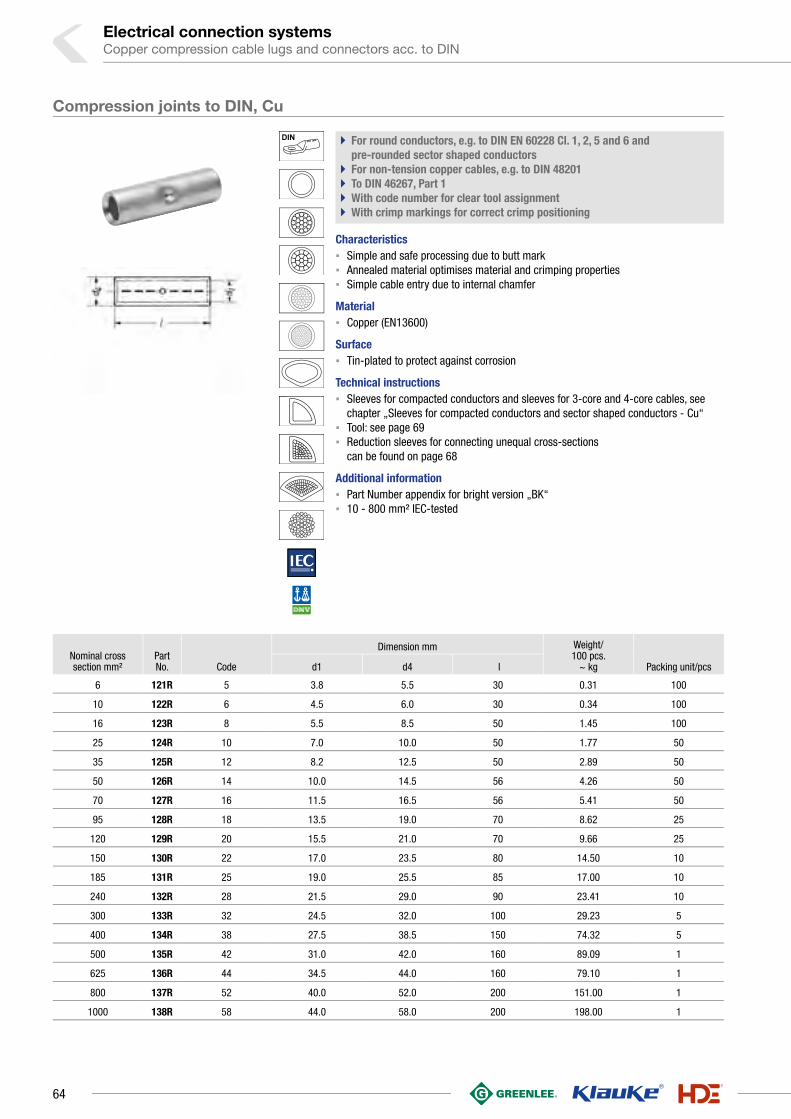
Nominal cross section mm²
Part No. Code
Dimension mm Weight/ 100 pcs.
~ kg Packing unit/pcsd1 d4 l
6 121R 5 3.8 5.5 30 0.31 100
10 122R 6 4.5 6.0 30 0.34 100
16 123R 8 5.5 8.5 50 1.45 100
25 124R 10 7.0 10.0 50 1.77 50
35 125R 12 8.2 12.5 50 2.89 50
50 126R 14 10.0 14.5 56 4.26 50
70 127R 16 11.5 16.5 56 5.41 50
95 128R 18 13.5 19.0 70 8.62 25
120 129R 20 15.5 21.0 70 9.66 25
150 130R 22 17.0 23.5 80 14.50 10
185 131R 25 19.0 25.5 85 17.00 10
240 132R 28 21.5 29.0 90 23.41 10
300 133R 32 24.5 32.0 100 29.23 5
400 134R 38 27.5 38.5 150 74.32 5
500 135R 42 31.0 42.0 160 89.09 1
625 136R 44 34.5 44.0 160 79.10 1
800 137R 52 40.0 52.0 200 151.00 1
1000 138R 58 44.0 58.0 200 198.00 1
Electrical connection systemsCopper compression cable lugs and connectors acc. to DIN
Compression joints to DIN, Cu
` For round conductors, e.g. to DIN EN 60228 Cl. 1, 2, 5 and 6 and pre-rounded sector shaped conductors
` For non-tension copper cables, e.g. to DIN 48201` To DIN 46267, Part 1` With code number for clear tool assignment` With crimp markings for correct crimp positioning
Characteristics▪ Simple and safe processing due to butt mark▪ Annealed material optimises material and crimping properties▪ Simple cable entry due to internal chamfer
Material▪ Copper (EN13600)
Surface▪ Tin-plated to protect against corrosion
Technical instructions▪ Sleeves for compacted conductors and sleeves for 3-core and 4-core cables, see
chapter „Sleeves for compacted conductors and sector shaped conductors - Cu“▪ Tool: see page 69▪ Reduction sleeves for connecting unequal cross-sections
can be found on page 68
Additional information▪ Part Number appendix for bright version „BK“▪ 10 - 800 mm² IEC-tested
64

Nominal cross section mm²
Part No. Code
Dimension mm Weight/ 100 pcs.
~ kg Packing unit/pcsd1 d4 l
16 523R 8 5.5 8.5 50 1.54 25
25 524R 10 7.0 10.0 50 1.84 25
35 525R 12 8.2 12.5 50 2.99 25
50 526R 14 10.0 14.5 56 4.46 25
70 527R 16 11.5 16.5 56 5.61 25
95 528R 18 13.5 19.0 70 8.88 25
120 529R 20 15.5 21.0 70 10.06 5
150 530R 22 17.0 23.5 80 14.89 5
185 531R 25 19.0 25.5 85 17.57 5
240 532R 28 21.5 29.0 90 24.23 5
300 533R 32 24.5 32.0 100 30.15 5
400 534R 38 27.5 38.5 150 75.60 5
500 535R 42 31.0 42.0 160 92.00 1
625 536R 44 34.5 44.0 160 81.50 1
Compression joints, Cu
` For round conductors, e.g. to DIN EN 60228 Cl. 1, 2, 5 and 6 and pre-rounded sector shaped conductors
` For non-tension copper cables, e.g. to DIN 48201` Barrier design with oil stop` Tube dimension to DIN 46267, part 1` With code number for clear tool assignment
Characteristics▪ Easy to process due to crimp markings▪ Annealed material optimises material and crimping properties▪ Simple cable entry due to internal chamfer
Suitable for▪ Non-tension connections
Material▪ Copper (EN13600)
Surface▪ Tin-plated to protect against corrosion
Technical instructions▪ Sleeves for compacted conductors and sleeves for 3-core and 4-core cables, see
chapter „Sleeves for compacted conductors and sector shaped conductors - Cu“▪ Tool: see page 69▪ Reduction sleeves for connecting unequal cross-sections
can be found on page 68
Additional information▪ Part Number appendix for bright version „BK“
65
1

Nominal cross section mm²
Part No. Code
Dimension mm Number of crimps Weight/ 100 pcs.
~ kg Packing unit/pcsd1 l Cu (5 mm) Cu (wide)
Standard version
25 504R 12 7.5 60 2/2 1/1 4.08 10
35 505R 12 8.2 60 2/2 1/1 3.56 10
50 506R 14 10.0 65 3/3 1/1 4.90 10
70 507R 16 11.5 65 3/3 1/1 6.10 10
95 508R 18 13.5 90 4/4 2/2 10.98 10
120 509R 20 15.5 90 4/4 2/2 12.68 5
150 510R 22 17.0 105 4/4 2/2 18.09 5
185 511R 25 19.0 105 4/4 2/2 20.35 5
240 512R 28 21.5 125 2/2 31.64 5
300 513R 32 24.5 125 2/2 35.40 1
400 514R 38 27.5 160 3/3 75.42 1
Barrier version
25 504RLD 12 7.5 60 2/2 1/1 4.08 25
35 505RLD 12 8.2 60 2/2 1/1 3.56 10
50 506RLD 14 10.0 65 3/3 1/1 4.90 10
70 507RLD 16 11.5 65 3/3 1/1 6.40 10
95 508RLD 18 13.5 90 4/4 2/2 10.98 10
120 509RLD 20 15.5 90 4/4 2/2 12.68 5
150 510RLD 22 17.0 105 4/4 2/2 18.84 5
185 511RLD 25 19.0 105 4/4 2/2 20.35 5
240 512RLD 28 21.5 125 2/2 31.64 5
300 513RLD 32 24.5 125 2/2 35.40 1
400 514RLD 38 27.5 160 3/3 75.42 1
Electrical connection systemsCopper compression cable lugs and connectors acc. to DIN
Compression joint for cable connections 10-30 kV, copper
` For round conductors, e.g. to DIN EN 60228 Cl. 2 and pre-rounded sector shaped conductors
` For non-tension copper cables, e.g. to DIN 48201` Tube dimension to DIN 46267, part 1` For copper medium-voltage cable connections 10 - 30 kV` With chamfered edges for reduced electrical stress in the assembly
Characteristics▪ Also available as barrier design with oil stop▪ Easy to process due to crimp markings▪ Annealed material optimises material and crimping properties▪ Simple cable entry due to internal chamfer
Suitable for▪ Non-tension connections
Material▪ Copper (EN13600)
Surface▪ Bright
Technical instructions▪ Tool: see page 69▪ Reduction sleeves for connecting unequal cross-sections can be found on page 68
Additional information▪ Part Number appendix for tinned version „V“
66

Nominal cross
section mm²Part No. Hint Code
Dimension mm Number of crimpsconductor dia. mm
Weight/ 100 pcs.
~ kgPacking unit/pcsd1 d4 l Cu (5 mm) Cu (wide)
6 181R * 6 3.5 6.5 65 4/4 3.00 1.4 10
10 182R 8 4.5 8.5 80 5/5 4.05 3.0 10
16 183R 8 5.5 8.5 95 5/5 5.10 2.8 10
25 184R 10 7.0 10.0 95 5/5 6.30 3.4 10
35 185R 12 8.2 12.5 95 5/5 7.50 5.6 10
50 186R 14 10.0 14.5 110 5/5 9.00 8.6 10
70 187R 16 11.5 16.5 110 5/5 10.50 10.8 10
95 188R 20 13.5 21.0 145 8/8 4/4 12.50 26.2 10
120 189R 22 15.0 23.5 160 8/8 4/4 14.00 36.8 10
150 190R 25 16.5 25.5 180 8/8 4/4 15.70 47.5 5
185 191R * 32 18.5 31.5 260 5/5 17.50 118.0 5
240 192R * 34 21.0 34.5 310 6/6 20.20 163.0 5
300 193R * 38 23.5 38.5 360 7/7 22.50 235.0 1
Compression joints to DIN, Cu
` For connecting copper cables to DIN 48201, Part 1` For full tension cable connections` To DIN 48085, Part 1` With code number for clear tool assignment` With crimp markings for correct crimping
Characteristics▪ Easy to process due to crimp markings▪ Simple and safe processing due to butt mark▪ Simple cable entry due to internal chamfer
Material▪ Copper (EN13600)
Surface▪ Bright
Technical instructions▪ To process item 192R use crimping die HAD45240▪ Tool: see page 69
Additional information▪ * = not standardised▪ 16 - 70 mm² IEC-tested
67
1

Part No.Nominal cross
section mm² fromNominal cross section mm² to
Dimension mm Weight/ 100 pcs.
~ kg Packing unit/pcs d1 d4 l
RH2510 25 10 4.6 6.6 25 0.358 25
RH2516 25 16 5.5 6.6 25 0.350 25
RH3510 35 10 4.5 8.0 25 0.707 25
RH3516 35 16 5.5 8.0 25 0.570 25
RH3525 35 25 7.0 8.0 25 0.253 25
RH5016 50 16 5.5 9.5 33 1.326 25
RH5025 50 25 7.0 9.5 33 0.923 25
RH5035 50 35 8.5 9.5 33 0.404 25
RH7025 70 25 7.0 11.0 33 1.580 25
RH7035 70 35 8.5 11.0 33 1.102 25
RH7050 70 50 10.0 11.0 33 0.486 25
RH9535 95 35 8.5 13.0 45 2.940 25
RH9550 95 50 10.0 13.0 45 2.136 25
RH9570 95 70 11.5 13.0 45 1.100 25
RH12050 120 50 10.0 15.0 45 3.802 25
RH12070 120 70 11.5 15.0 45 2.874 25
RH12095 120 95 13.5 15.0 45 1.340 25
RH15070 150 70 11.5 16.5 53 5.008 5
RH15095 150 95 13.5 16.5 53 3.212 5
RH150120 150 120 15.5 16.5 53 1.248 5
RH18595 185 95 13.5 18.5 53 5.824 5
RH185120 185 120 15.5 18.5 53 3.756 5
RH185150 185 150 17.0 18.5 53 1.660 5
RH240120 240 120 15.5 21.0 55 7.412 5
RH240150 240 150 17.0 21.0 55 5.740 5
RH240185 240 185 19.0 21.0 55 3.036 5
RH300150 300 150 17.0 24.0 58 11.200 5
RH300185 300 185 19.0 24.0 58 8.390 5
RH300240 300 240 21.5 24.0 58 4.526 5
RH400185 400 185 19.0 27.0 80 20.100 5
RH400240 400 240 21.5 27.0 80 14.270 5
RH400300 400 300 24.5 27.0 80 8.800 5
Electrical connection systemsCopper compression cable lugs and connectors acc. to DIN
Reduction sleeves, Cu
` For multi-stranded, round conductors e.g. to DIN EN 60228` For connecting different conductor cross-sections` For use in DIN compression joints and connectors, standard type` For non-tension copper cables acc. to DIN 48201 part 1
Characteristics▪ Simple cable entry due to internal chamfer
Suitable for▪ For non-tension compression joints
Material▪ Copper (EN13600)
Surface▪ Bright
Technical instructions▪ Refer to the installation instructions in the technical appendix on page i-7
68

Mechanical crimping tools
6-50 K05D 235
10-120 K06D 237
25-150 K09D 238
Mechanical, electrical, pneumatic crimping tools with interchangeable dies / heads
6-120 K354 246 330
6-185 K18 248 338
6-240 K22 250 343
Hand hydraulic crimping tools
6-185 HK6018 292 338
HK60UNV +UA18 473 338
6-300 HK6022 294 343
HK60UNV +UA22 473 343
16-300 HK12030 298 348
HK12042 300 348
HK120U 302 348
120-1000 HK45 321 358
Battery powered crimping tools
6-120 EK354ML 262 330
EK354 266 330
6-185 EK505 268 334
EK5018 270 338
EK60UNV +UA18 476 338
EKM60UNV +UA18 475 338
6-300 EK6022 247 343
EKM6022 272 343
EK60UNV +UA22 476 343
EKM60UNV +UA22 475 343
16-300 EK12032 280 348
EK12042 282 348
EK120U 284 348
EK120UNV +UA12T 477 348
EK135FT +UA15T 286 348
400-625 EK135FT 286 352
Hydraulic crimping systems
6-185 THK18 306 338
6-240 THK22 308 343
HK122EL380 322 343
16-625 HK252 320 354
HK252EL380 323 354
Hydraulic crimping heads
6-185 PK18 306 338
PK60UNV +UA18 474 338
6-300 PK22 308 343
PK60UNV +UA22 474 343
16-300 PK12042 312 348
PK120U 314 348
16-625 PK252 316 354
120-1000 PK45 318 358
Tool application chart
Compression cable lugs and compression joints
Tool type
Crimping range corresponds to nominal cross-section mm²
Crimping Tool Catalogue page
Crimp profilePart No.Crimping head / adapter Crimping Tool Crimping die
69
1

Mechanical, electrical, pneumatic crimping tools with interchangeable dies / heads
2x50-2x70 K22 250 343
Hand hydraulic crimping tools
2x50-2x70 HK6022 294 343
HK60UNV +UA22 473 343
2x50-2x95 HK12030 298 348
HK12042 300 348
HK120U 302 348
Battery powered crimping tools
2x50-2x70 EK6022 274 343
EKM6022 272 343
EK60UNV +UA22 476 343
EKM60UNV +UA22 475 343
2x50-2x95 EK12032 280 348
EK12042 282 348
EK120U 284 348
EK135FT +UA15T 286 348
EK120UNV +UA12T 477 348
Hydraulic crimping systems
2x50-2x70 THK22 308 343
2x50-2x95 HK122EL380 322 348
2x50-2x120 HK252 320 354
HK252EL380 323 354
Hydraulic crimping heads
2x50-2x70 PK22 308 343
PK60UNV +UA22 474 343
2x50-2x95 PK12042 312 348
PK120U 314 348
2x50-2x120 PK252 316 354
Tool application chart
Double compression cable lugs
Tool type
Crimping range corresponds to nominal cross-section mm²
Crimping Tool Catalogue page
Crimp profilePart No.Crimping head / adapter Crimping Tool Crimping die
Electrical connection systemsCopper compression cable lugs and connectors acc. to DIN
70

71
1

Terminals, connectors and pin terminals to DIN - CuElectrical connection systems
PUNCHED - SOLDERLESS TERMINALS MADE FROM COPPER TO DIN 46234Unlike the tubular cable lugs, Klauke solderless terminals are punched from a sheet,
bent and then hard soldered in the crimp area. The grooved profile on the inside
ensures higher conductor pull-out values. This product’s small dimensions make it
the ideal solution for confined areas.
In brief
`` Reliable crimping due to high-quality solder seam
`` Small dimensions for confined areas
`` Suitable for multi-stranded, fine-stranded and superfine-stranded conductors
72

` Well insulated
Klauke products make your day-to-day work easier.
Thanks to the widened insulation, the conductor can be very
conveniently inserted into our insulated solderless terminals.
The insulation remains intact even after crimping, eliminating
the need for retrospective insulation. Everything accomplished
in one operation.
◾ Easy to use thanks to widened sleeve
◾ No additional insulation, hence fast processing
◾ As a fork-type, ideal for connecting meters in
confined areas for example
◾ Easy conductor insertion thanks to widened sleeve
` Hard soldered for reliable contact
The quality of Klauke cable lugs is also evident during the
crimping operation: The solderless terminal always remains
intact due to the high-quality solder seam. Guaranteed quality.
◾ Reliable contact due to high-quality solder seam
and tinning
◾ Best possible contacting with ribbed profile
◾ Optimum solution for confined areas thanks to
highly-compact dimensions
◾ Insulated and non-insulated versions
73
1

Nominal cross section
mm²
Nominal size
to DIN Part No. Hint
Dimension mm Weight/ 100 pcs.
~ kgPacking unit/pcs a b d1 d2 l s
0.5 - 1
2.5 - 1 162025 5 6 1.6 2.8 11 0.8 0.060 100
3 - 1 16203 5 6 1.6 3.2 11 0.8 0.060 100
3.5 - 1 162035 5 6 1.6 3.7 11 0.8 0.055 100
4 - 1 16204 5 8 1.6 4.3 12 0.8 0.070 100
5 - 1 16205 5 10 1.6 5.3 13 0.8 0.090 100
6 - 1 16206 * 5 11 1.6 6.5 15 0.8 0.080 100
8 - 1 16208 * 5 14 1.6 8.4 17 0.8 0.130 100
10 - 1 162010 * 5 18 1.6 10.5 19 0.8 0.130 100
1.5 - 2.5
3 - 2.5 16303 5 6 2.3 3.2 11 0.8 0.065 100
4 - 2.5 16304 5 8 2.3 4.3 12 0.8 0.080 100
3.5 - 2.5 163035 5 6 2.3 3.7 11 0.8 0.065 100
5 - 2.5 16305 5 10 2.3 5.3 14 0.8 0.090 100
6 - 2.5 16306 5 11 2.3 6.5 16 0.8 0.110 100
8 - 2.5 16308 5 14 2.3 8.4 17 0.8 0.130 100
10 - 2.5 163010 * 5 15 2.3 10.5 17 0.8 0.160 100
12 - 2.5 163012 * 5 18 2.3 13.0 19 0.8 0.160 100
4 - 6
4 - 6 16504 6 8 3.6 4.3 14 1.0 0.140 100
5 - 6 16505 6 10 3.6 5.3 15 1.0 0.160 100
6 - 6 16506 6 11 3.6 6.5 16 1.0 0.170 100
8 - 6 16508 6 14 3.6 8.4 19 1.0 0.220 100
10 - 6 165010 6 18 3.6 10.5 21 1.0 0.290 100
12 - 6 165012 * 6 18 3.6 13.0 21 1.0 0.280 100
10
5 - 10 16525 8 10 4.5 5.3 16 1.1 0.230 100
6 - 10 16526 8 11 4.5 6.5 17 1.1 0.24 100
8 - 10 16528 8 14 4.5 8.4 20 1.1 0.340 100
10 - 10 165210 8 18 4.5 10.5 21 1.1 0.340 100
12 - 10 165212 8 22 4.5 13.9 23 1.1 0.420 100
16
5 - 16 16535 10 11 5.8 5.3 20 1.2 0.390 100
6 - 16 16536 10 11 5.8 6.5 20 1.2 0.380 100
8 - 16 16538 10 14 5.8 8.4 22 1.2 0.43 100
10 - 16 165310 10 18 5.8 10.5 24 1.2 0.500 100
12 - 16 165312 10 18 5.8 10.5 24 1.2 0.500 100
see next page
Electrical connection systemsTerminals, connectors and pin terminals to DIN - Cu
Solderless terminals to DIN, Cu
` For round conductors, e.g. to DIN EN 60228 Cl. 2, 5 and 6` To DIN 46234` High-quality brazing process in the crimp area
Characteristics▪ Improved contact properties due to grooved profile
Material▪ Copper (ETP)
Surface▪ Tin-plated to protect against corrosion
Technical instructions▪ Tool: see page 82
Additional information▪ * = not standardised▪ 0.5 - 6 mm² not UL-tested
74

Nominal cross section
mm²
Nominal size
to DIN Part No. Hint
Dimension mm Weight/ 100 pcs.
~ kgPacking unit/pcs a b d1 d2 l s
25
5 - 25 16545 11 12 7.5 5.3 25 1.5 0.750 100
6 - 25 16546 11 12 7.5 6.5 25 1.5 0.750 100
8 - 25 16548 11 16 7.5 8.4 25 1.5 0.750 100
10 - 25 165410 11 18 7.5 10.5 26 1.5 0.750 100
12 - 25 165412 11 22 7.5 13.0 31 1.5 0.920 100
16 - 25 165416 11 28 7.5 17.0 35 1.5 1.320 100
35
6 - 35 16556 12 16 9.0 8.4 26 1.6 0.980 100
8 - 35 16558 12 16 9.0 8.4 26 1.6 0.980 100
10 - 35 165510 12 18 9.0 10.5 27 1.6 1.000 100
12 - 35 165512 12 22 9.0 13.0 31 1.6 1.260 100
16 - 35 165516 12 28 9.0 17.0 36 1.6 1.550 100
50
6 - 50 16566 16 18 11.0 6.5 34 1.8 1.650 100
8 - 50 16568 16 18 11.0 8.4 34 1.8 1.650 100
10 - 50 165610 16 18 11.0 10.5 34 1.8 1.600 100
12 - 50 165612 16 22 11.0 13.0 36 1.8 1.800 100
16 - 50 165616 16 28 11.0 17.0 40 1.8 2.100 100
70
6 - 70 16576 18 22 13.0 6.5 38 2.0 2.600 50
8 - 70 16578 18 22 13.0 8.4 38 2.0 2.500 50
10 - 70 165710 18 22 13.0 10.5 38 2.0 2.500 50
12 - 70 165712 18 22 13.0 13.0 38 2.0 2.400 50
16 - 70 165716 18 28 13.0 17.0 42 2.0 2.700 50
95
8 - 95 16588 20 24 15.0 8.4 42 2.5 4.300 50
10 - 95 165810 20 24 15.0 10.5 42 2.5 4.1 50
12 - 95 165812 20 24 15.0 13.0 42 2.5 3.900 50
16 - 95 165816 20 28 15.0 17.0 44 2.5 4.100 50
120
8 - 120 16598 22 24 17.0 8.4 44 3.0 5.601 50
10 - 120 165910 22 24 17.0 10.5 44 3.0 5.600 50
12 - 120 165912 22 24 17.0 13.0 44 3.0 5.400 50
16 - 120 165916 22 28 17.0 17.0 48 3.0 5.800 50
150
10 - 150 166010 24 30 19.0 10.5 50 3.2 7.600 50
12 - 150 166012 24 30 19.0 13.0 50 3.2 7.600 50
16 - 150 166016 24 30 19.0 17.0 50 3.2 7.500 50
18512 - 185 166112 28 36 21.0 13.0 50 3.5 11.300 50
16 - 185 166116 28 36 21.0 17.0 50 3.5 11.300 50
24012 - 240 166212 32 38 23.5 13.0 56 4.0 15.900 25
16 - 240 166216 32 38 23.5 17.0 56 4.0 15.900 25
Solderless terminals to DIN, Cu
75
1

Nominal cross section mm²
Part No. Colour
Dimension mm Gewicht 100 St. ~kg
Cu
Gewicht 100 St. ~kg
Ges.Packing unit/
pcsd12 d13 d2 Gl1 l10
10
6525 6.7 8.6 5.3 34.0 19.0 0.27 0.27 100
6526 6.7 8.6 6.5 34.0 19.0 0.24 0.28 100
6528 6.7 8.6 8.4 37.5 19.0 0.29 0.33 100
65210 6.7 8.6 10.5 41.5 19.0 0.34 0.38 100
65212 6.7 8.6 13.0 45.5 19.0 0.42 0.46 100
16
6535 7.7 9.6 5.3 39.5 20.5 0.39 0.44 100
6536 7.7 9.6 6.5 39.5 20.5 0.38 0.43 100
6538 7.7 9.6 8.4 41.5 20.5 0.43 0.48 100
65310 7.7 9.6 10.5 43.5 20.5 0.50 0.55 100
65312 7.7 9.6 13.0 50.5 20.5 0.58 0.63 100
25
6545 11.0 13.0 5.3 40.0 20.0 0.75 0.84 50
6546 11.0 13.0 6.5 42.5 20.0 0.69 0.78 50
6548 11.0 13.0 8.4 43.0 20.0 0.75 0.84 50
65410 11.0 13.0 10.5 45.0 20.0 0.80 0.89 50
65412 11.0 13.0 13.0 51.0 20.0 0.92 1.00 50
65416 11.0 13.0 17.0 59.0 20.0 1.32 1.40 50
35
6556 12.7 15.0 6.5 44.0 22.5 1.01 1.14 50
6558 12.7 15.0 8.4 44.5 22.5 0.98 1.10 50
65510 12.7 15.0 10.5 46.5 22.5 1.00 1.12 50
65512 12.7 15.0 13.0 52.5 22.5 1.26 1.38 50
65516 12.7 15.0 17.0 54.5 22.5 1.55 1.67 50
50
6566 15.4 18.0 6.5 54.5 27.5 1.65 1.90 50
6568 15.4 18.0 8.4 60.5 27.5 1.65 1.90 50
65610 15.4 18.0 10.5 60.5 27.5 1.60 1.85 50
65612 15.4 18.0 13.0 60.5 27.5 1.80 2.05 50
65616 15.4 18.0 17.0 67.5 27.5 2.10 2.35 50
see next page
Electrical connection systemsTerminals, connectors and pin terminals to DIN - Cu
Insulated solderless terminals, Cu with Easy-Entry
` For round conductors, e.g. to DIN EN 60228 Cl. 2, 5 and 6` High-quality brazing process in the crimp area` Fast preparation as no additional insulation of the crimped connection is
required` Simple processing due to crimping over the insulation
Characteristics▪ Insulating, halogen-free with easy-entry cable insertion▪ Dimensions in tube according to DIN 46234▪ Improved contact properties due to grooved profile▪ Cross-section-dependent colour-coding▪ Heat resistant to 105° C
Material▪ Copper (ETP)▪ Insulation sleeve: PA
Surface▪ Tin-plated to protect against corrosion
Technical instructions▪ Tool: see page 84
76

Nominal cross section mm²
Part No. Colour
Dimension mm Weight 100 pcs. ~kg
Cu
Weight 100 pcs. ~kg
TotalPacking unit/
pcsd12 d13 d2 Gl1 l10
70
6576 17.4 20.0 6.5 61.5 30.5 2.60 2.90 50
6578 17.4 20.0 8.4 61.5 30.5 2.50 2.80 50
65710 17.4 20.0 10.5 66.5 30.5 2.50 2.80 50
65712 17.4 20.0 13.0 66.5 30.5 2.40 2.70 50
65716 17.4 20.0 17.0 70.5 30.5 2.70 3.00 50
95
65810 20.5 23.5 10.5 70.0 34.0 4.10 4.50 25
65812 20.5 23.5 13.0 70.0 34.0 3.90 4.40 25
65816 20.5 23.5 17.0 76.0 34.0 4.10 4.50 25
120
65910 23.5 26.7 10.5 79.0 36.0 5.60 6.10 25
65912 23.5 26.7 13.0 82.0 36.0 5.40 5.90 25
65916 23.5 26.7 17.0 90.0 36.0 5.80 6.30 25
150
66010 26.0 29.2 10.5 80.0 39.0 7.60 8.40 25
66012 26.0 29.2 13.0 83.0 39.0 7.60 8.40 25
66016 26.0 29.2 17.0 83.0 39.0 7.50 8.30 25
Nominal cross section mm² Part No. Colour
Dimension mm Weight 100 pcs. ~kg
Cu
Weight 100 pcs. ~kg
TotalPacking unit/
pcsb d12 d13 Gl1 l10
10 ST1716IS 4.3 7.4 9.4 33.0 19.0 0.27 0.31 100
16 ST1717IS 5.5 8.6 10.6 38.0 20.0 0.39 0.44 100
25 ST1718IS 6.8 12.5 14.5 43.5 23.5 0.63 0.73 50
35 ST1719IS 8.0 14.0 16.4 51.5 27.5 1.17 1.34 50
50 ST1720IS 9.5 15.5 18.0 59.0 33.0 1.79 2.10 50
70 ST1721IS 11.0 18.0 20.5 69.0 38.0 2.92 3.20 50
95 ST1722IS 12.5 20.7 23.5 71.0 40.0 4.30 4.70 25
Insulated solderless terminals, Cu with Easy-Entry
Insulated pin terminals, Cu with Easy-Entry
` For round conductors, e.g. to DIN EN 60228 Cl. 2, 5 and 6` High-quality brazing process in the crimp area` Fast preparation as no additional insulation of the crimped connection
is required
Characteristics▪ Insulating, halogen-free with easy-entry cable insertion▪ Improved contact properties due to grooved profile▪ Cross-section-dependent colour-coding▪ Heat resistant to 105° C
Material▪ Copper (ETP)▪ Insulation sleeve: PA
Surface▪ Tin-plated to protect against corrosion
Technical instructions▪ Tool: see page 84
77
1

Nominal cross section
mm²Nominal size
to DIN Part No.
Dimension mm Weight 100 pcs.
~kgPacking unit/
pcsa b d1 d2 l s
0.5 - 1
3 - 1 1620C3 5.0 6.0 1.6 3.2 11.0 0.8 0.060 100
3.5 - 1 1620C35 5.0 6.0 1.6 3.7 11.0 0.8 0.060 100
4 - 1 1620C4 5.0 6.8 1.6 4.3 12.0 0.8 0.070 100
5 - 1 1620C5 5.0 10.0 1.6 5.3 13.0 0.8 0.090 100
6 - 1 1620C6 5.0 11.0 1.6 6.5 15.0 0.8 0.080 100
1.5 - 2.5
3 - 2.5 1630C3 5.0 5.5 2.3 3.2 13.8 0.8 0.065 100
3.5 - 2.5 1630C35 5.0 6.0 2.3 3.7 11.0 0.8 0.065 100
4 - 2.5 1630C4 5.0 6.8 2.3 4.3 12.0 0.8 0.080 100
5 - 2.5 1630C5 5.0 10.0 2.3 5.3 14.0 0.8 0.090 100
6 - 2.5 1630C6 5.0 11.0 2.3 6.5 16.0 0.8 0.110 100
4 - 6
4 - 6 1650C4 6.0 8.0 3.6 4.3 14.0 1.0 0.140 100
5 - 6 1650C5 6.0 10.0 3.6 5.3 15.0 1.0 0.160 100
6 - 6 1650C6 6.0 11.0 3.6 6.5 16.0 1.0 0.170 100
8 - 6 1650C8 6.0 14.0 3.6 8.4 19.0 1.0 0.220 100
105 - 10 1652C5 10.0 10.0 4.3 5.3 19.0 1.0 0.240 100
6 - 10 1652C6 10.0 11.0 4.3 6.4 21.0 1.0 0.260 100
166 - 16 1653C6 11.5 11.0 5.4 6.4 24.0 1.0 0.350 100
8 - 16 1653C8 11.5 15.0 5.4 8.4 27.0 1.0 0.420 100
Electrical connection systemsTerminals, connectors and pin terminals to DIN - Cu
Solderless terminals, Cu, fork type
` For round conductors, e.g. to DIN EN 60228 Cl. 2, 5 and 6` Dimensions in tube to 6 mm² to DIN 46234` Simple fork-type mounting` High-quality brazing process in the crimp area
Characteristics▪ Improved contact properties due to grooved profile
Material▪ Copper (ETP)
Surface▪ Tin-plated to protect against corrosion
Technical instructions▪ Tool: see page 82
Additional information▪ 0.5 - 6 mm² not UL-certified
78

Nominal cross
section mm²
Nominal size
to DIN Part No. Typ Hint
Dimension mm Weight 100 pcs.
~kgPacking unit/pcs a b d1 d2 l1 l2 s h
0.5 - 1 1 ST1705 A 5.0 -- 1.8 1.9 17.0 10 0.8 -- 0.060 100
1.5 - 2.5 2.5 ST1710 A 5.0 -- 2.3 1.9 17.0 10 0.8 -- 0.072 100
4 - 6 6 ST1715 A 6.0 -- 3.6 2.7 20.0 11 1.0 -- 0.160 100
10 -- ST1716 B * 10.0 4.3 4.3 -- 24.5 11 1.0 2.0 0.270 100
16 -- ST1717 B * 11.5 5.8 5.4 -- 29.5 15 1.0 2.0 0.390 100
25 -- ST1718 B * 13.5 6.8 6.7 -- 33.5 15 1.2 2.4 0.630 100
35 -- ST1719 B * 16.0 8.0 8.2 -- 40.5 20 1.5 3.2 1.170 50
50 -- ST1720 B * 19.0 9.5 9.5 -- 45.0 20 1.8 3.6 1.790 50
70 -- ST1721 B * 24.0 11.0 11.2 -- 55.0 23 2.0 4.0 2.920 50
95 -- ST1722 B * 24.0 12.5 13.5 -- 55.0 23 2.5 5.0 4.300 50
Pin terminals to DIN, Cu
` For round conductors, e.g. to DIN EN 60228 Cl. 2, 5 and 6` Nominal cross-sections 0.5 - 6 mm² to DIN 46230` High-quality brazing process in the crimp area
Characteristics▪ Improved contact properties due to grooved profile
Material▪ Copper (ETP)
Surface▪ Tin-plated to protect against corrosion
Technical instructions▪ Tool: see page 82
Additional information▪ * = not standardised▪ 0.5 - 6 mm² not UL-tested
79
1

Nominal cross section mm²
Part No. Colour
Dimension mm Gewicht 100 St. ~kg
Cu
Gewicht 100 St. ~kg
Ges.Packing unit/
pcsd12 d13 d2 Gl1 l10
10652C5 7.0 9.6 5.3 33.5 19.0 0.24 0.28 100
652C6 7.0 9.6 6.4 33.5 19.0 0.26 0.30 100
16 653C6 8.6 10.6 6.4 37.5 20.5 0.35 0.40 100
Nominal cross section mm²
Nominal size to DIN Part No.
Dimension mmWeight
100 pcs. ~kg Packing unit/pcsd1 d4 l
0.5 - 1 1 1620K 1.6 3.2 8 0.045 100
1.5 - 2.5 2.5 1630K 2.3 3.9 8 0.055 100
4 - 6 6 1650K 3.6 5.6 9 0.090 100
10 10 1652K 4.5 6.7 10 0.170 100
16 16 1653K 5.8 8.2 11 0.260 100
25 25 1654K 7.5 10.5 14 0.510 100
35 35 1655K 9.0 12.2 16 0.730 100
50 50 1656K 11.0 14.6 19 1.200 100
70 70 1657K 13.0 17.0 19 1.530 50
95 95 1658K 15.0 20.0 20 2.370 50
120 120 1659K 16.5 22.5 22 3.450 50
150 150 1660K 19.0 25.4 26 5.060 50
Electrical connection systemsTerminals, connectors and pin terminals to DIN - Cu
Insulated solderless terminals for meter connections, Cu, fork type
` For round conductors, e.g. to DIN EN 60228 Cl. 2, 5 and 6` Special design for meter connection` High-quality brazing process in the crimp area` Fast preparation as no additional insulation of the crimped connection is
required
Characteristics▪ Improved contact properties due to grooved profile▪ Cross-section-dependent colour-coding▪ Heat resistant to 105° C
Material▪ Copper (ETP)▪ Insulation sleeve: PA
Surface▪ Tin-plated to protect against corrosion
Technical instructions▪ Tool: see page 84
Solderless connectors to DIN, Cu, short type
` For round conductors, e.g. to DIN EN 60228 Cl. 2, 5 and 6` To DIN 46341, Part 1, Form A` Ideal for connecting differing conductor cross-sections
Characteristics▪ Simple cable entry due to internal chamfer▪ Annealed material optimises material and crimping properties
Material▪ Copper (EN13600)
Surface▪ Tin-plated to protect against corrosion
Technical instructions▪ Tool: see page 82
80

Nominal cross section mm²
Nominal size to DIN Part No.
Dimension mmWeight
100 pcs. ~kg Packing unit/pcsd1 d4 l
0.5 - 1 1 1620L 1.6 3.2 15 0.08 100
1.5 - 2.5 2.5 1630L 2.3 3.9 15 0.10 100
4 - 6 6 1650L 3.6 5.6 15 0.19 100
10 10 1652L 4.5 6.7 21 0.36 100
16 16 1653L 5.8 8.2 26 0.62 100
25 25 1654L 7.5 10.5 29 1.11 100
35 35 1655L 9.0 12.2 32 1.50 100
50 50 1656L 11.0 14.6 38 2.44 100
70 70 1657L 13.0 17.0 42 3.54 50
95 95 1658L 15.0 20.0 48 5.87 50
120 120 1659L 16.5 22.5 52 8.46 50
150 150 1660L 19.0 25.4 56 10.86 50
Solderless connectors to DIN, Cu, long type
` For round conductors, e.g. to DIN EN 60228 Cl. 2, 5 and 6` To DIN 46341, Part 1, Form B` Simple and safe processing due to butt mark
Characteristics▪ Simple cable entry due to internal chamfer▪ Annealed material optimises material and crimping properties
Material▪ Copper (EN13600)
Surface▪ Tin-plated to protect against corrosion
Technical instructions▪ Tool: see page 82
81
1

Tool application chart
Solderless terminals to DIN 46234, pin terminals to DIN 46230, solderless connectors to DIN 46341 Part 1 of 2
Mechanical crimping tools
0.5-16 K25 230
16-95 K95 230
TK95 231
Mechanical, electrical, pneumatic crimping tools with interchangeable dies / heads
0.5-10 K50 244 326
EK50ML 254 326
K507 243
0.75-2.5 KP1 +KP232 240
KP1L +KP232 240
4-10 KP1 +KP242 240
KP1L +KP242 240
10-35 K354 246 330
10-70 K18 248 338
K22 250 343
Hand hydraulic crimping tools
10-70 HK6018 292 338
HK60UNV +UA18 473 338
HK6022 294 343
HK60UNV +UA22 473 343
16-150 HK12030 298 349
HK12042 300 349
HK120U 302 349
Battery powered crimping tools
0.5-10 EK1550ML 258 326
0.75-2.5 EKP1ML +KP232 260
4-10 EKP1ML +KP242 260
10-35 EK354ML 262 330
EK354 266 330
10-50 EK505 268 334
10-70 EK5018 270 338
EK60UNV +UA18 476 338
EKM60UNV +UA18 475 338
EK6022 247 343
EKM6022 272 343
EK60UNV +UA22 476 343
EKM60UNV +UA22 475 343
10-240 EKM60ID 278
16-150 EK12032 280 349
EK12042 282 349
EK120U 284 349
EK135FT +UA15T 286 349
EK120UNV +UA12T 477 349
35-240 EK120ID 279
see next page
Electrical connection systemsTerminals, connectors and pin terminals to DIN - Cu
Tool type
Crimping range corresponds to nominal cross-section mm²
Crimping Tool Catalogue page
Crimp profilePart No.Crimping head / adapter Crimping Tool Crimping die
82

Hydraulic crimping systems
10-70 THK18 306 338
THK22 308 343
16-150 HK122EL380 322 349
16-240 HK252 320 354
HK252EL380 323 354
Hydraulic crimping heads
10-70 PK18 306 338
PK60UNV +UA18 474 338
PK22 308 343
PK60UNV +UA22 474 343
10-240 PK60ID 311
16-150 PK12042 312 349
PK120U 314 349
16-240 PK252 316 354
Tool application chart
Solderless terminals to DIN 46234, pin terminals to DIN 46230, solderless connectors to DIN 46341 Part 2 of 2
Tool type
Crimping range corresponds to nominal cross-section mm²
Crimping Tool Catalogue page
Crimp profilePart No.Crimping head / adapter Crimping Tool Crimping die
83
1

Tool application chart
Isolierte QuetschkabelschuheIsolierte Stiftkabelschuhe
Mechanical crimping tools
10-16 K16 223
Mechanical, electrical, pneumatic crimping tools with interchangeable dies / heads
10-16 K50 244 327
EK50ML 254 327
K354 246 327
10-50 K18 248 338
10-70 K22 250 343
Hand hydraulic crimping tools
10-50 HK6018 292 338
HK60UNV +UA18 473 338
10-70 HK6022 294 343
HK60UNV +UA22 473 343
10-95 HK12030 298 349
HK12042 300 349
HK120U 302 349
Battery powered crimping tools
10-16 EK1550ML 258 327
EK354ML 262 330
EK354 266 330
10-50 EK5018 270 338
EK60UNV +UA18 476 338
EKM60UNV +UA18 475 338
10-70 EK6022 274 343
EKM6022 272 343
EK60UNV +UA22 476 343
EKM60UNV +UA22 475 343
10-95 EK12032 280 349
EK12042 282 349
EK120U 284 349
EK135FT +UA15T 286 349
EK120UNV +UA12T 477 349
Hydraulic crimping systems
10-50 THK18 306 338
10-70 THK22 308 343
10-150 HK252 320 355
Hydraulic crimping heads
10-50 PK18 306 338
PK60UNV +UA18 474 338
10-70 PK22 308 343
PK60UNV +UA22 474 343
10-95 PK12042 312 349
PK120U 314 349
10-150 PK252 316 355
Electrical connection systemsTerminals, connectors and pin terminals to DIN - Cu
Tool type
Crimping range corresponds to nominal cross-section mm²
Crimping Tool Catalogue page
Crimp profilePart No.Crimping head / adapter Crimping Tool Crimping die
84

85
1

In Kürze
`` zum Rundpressen von Sektorleitern
`` bringt verdichtete Leiter auf das gewünschte Volumen
`` guter Leitwert durch hochwertiges Kupfer
`` verfügbar für DIN- und Rohrkabelschuhe
Hint: Die Hülsen für Sektorleiter müssen mit Rund rückeneinsätzen verpresst werden.
Electrical connection systems
COMPENSATING - SLEEVES FOR COPPER SECTOR-SHAPED AND COMPACTED CONDUCTORSWith the right sleeve, copper sector-shaped conductors are easy to crimp all the way
round and can then be conveniently inserted into the cable lug. Klauke sleeves for
compacted conductors compensate the difference between the compacted conductor
and cable lug - ensuring reliable connections.
In brief
`` For round crimping sector-shaped conductors
`` Brings compacted conductors to the required volume
`` Good conductivity due to high-quality copper
`` Available for DIN and tubular cable lugs
Note: The sleeves for sector-shaped conductors must be crimped with pre-rounding dies.
Sleeves for compacted conductors and sector-shaped conductors - copper
86

` Pre-rounded sector-shaped conductors
Pre-rounds 3 and 4-sector-shaped conductors without special
cable lugs - using Klauke sleeves.
◾ For pre-rounding of sector-shaped conductors
◾ Suitable for 3- and 4-sector-shaped conductors at angles
of 120° and 90°
◾ Nominal cross-section up to 240 mm2
◾ No splicing of conductors
◾ No special cable lugs required
◾ Lower storage costs
` The right sleeve for every cable lug
With Klauke, everything fits together. The diameter and length
of the sleeve are adapted to the required cable lug to ensure
optimum crimping.
◾ Reliable crimping in a just a few steps
◾ Sleeves accurately matched to the Klauke system
` Filled in two steps
Making it easy for you: Use the Klauke sleeves to bring
compacted conductors to the required volume in just two work
steps: Simply attach the sleeve to the stripped conductor and
insert it into the appropriate cable lug - done.
No additional tools and no special solutions required.
◾ Simple filling of compacted conductors
◾ For nominal cross-sections of up to 400 mm2
◾ High-quality material reduces contact resistance
◾ No special solutions required: existing tool can be used
for reliable crimping
87
1

Electrical connection systems
Nominal cross section mm² Part No.
Dimension mmWeight
100 pcs. ~kg Packing unit/pcs d1 d4 l
16 VHR16 5.0 5.3 11 0.024 100
25 VHR25 6.4 6.7 14 0.038 100
35 VHR35 7.7 8.2 15 0.083 100
50 VHR50 9.0 9.5 18 0.118 50
70 VHR70 10.6 11.2 19 0.173 50
95 VHR95 12.4 13.0 21 0.223 50
120 VHR120 13.9 14.5 22 0.261 50
150 VHR150 15.4 16.0 26 0.342 25
185 VHR185 17.6 18.2 26 0.396 25
240 VHR240 19.9 20.5 30 0.508 25
300 VHR300 22.4 23.0 38 0.723 10
400 VHR400 25.4 26.2 38 1.108 10
Sleeves for compacted conductors, for tubular cable lugs and connector standard type
` For multi-stranded, compacted conductors e.g. to DIN EN 60228 Cl. 2` Allows the use of Klauke tubular cable lugs and connectors, standard type,
on compacted conductors
Characteristics▪ Annealed material optimises material and crimping properties
Material▪ Copper (HCP)
Surface▪ Tin-plated to protect against corrosion
Technical instructions▪ Refer to the installation instructions in the technical appendix on page i-7
Sleeves for compacted conductors and sector-shaped conductors - copper
88

Nominal cross section mm² Part No.
Dimension mmWeight
100 pcs. ~kg Packing unit/pcs d1 d4 l
16 VHD16 5.0 5.3 16 0.035 100
25 VHD25 6.4 6.7 16 0.043 100
35 VHD35 7.7 8.2 17 0.094 100
50 VHD50 9.0 9.5 23 0.151 50
70 VHD70 10.6 11.2 24 0.219 50
95 VHD95 12.4 13.0 28 0.298 50
120 VHD120 13.9 14.5 30 0.357 50
150 VHD150 15.4 16.0 30 0.395 25
185 VHD185 17.6 18.2 38 0.579 25
240 VHD240 19.9 20.5 38 0.645 25
300 VHD300 22.4 23.0 48 0.913 5
400 VHD400 25.4 26.2 58 1.692 5
Sleeves for compacted conductors, for tubular cable lugs and connector DIN type
` For multi-stranded, compacted conductors e.g. to DIN EN 60228 Cl. 2` Allows the use of Klauke DIN compression cable lugs and connectors for
compacted conductors
Characteristics▪ Annealed material optimises material and crimping properties
Material▪ Copper (HCP)
Surface▪ Tin-plated to protect against corrosion
Technical instructions▪ Refer to the installation instructions in the technical appendix on page i-7
89
1

Electrical connection systems
Nominal cross section mm² Part No. Dimension mm für lWeight
100 pcs. ~kg Packing unit/pcs
Standard type
35 VHR353 14 0.08 100
50 VHR503 17 0.17 50
70 VHR703 18 0.29 50
95 VHR953 22 0.45 50
120 VHR1203 23 0.49 50
150 VHR1503 25 0.58 25
185 VHR1853 25 0.80 25
240 VHR2403 30 1.04 25
DIN version
35 VHD353 17,5 0.11 100
50 VHD503 25,0 0.26 50
70 VHD703 25,0 0.39 50
95 VHD953 32,0 0.66 50
120 VHD1203 32,0 0.68 50
150 VHD1503 32,0 0.74 25
185 VHD1853 35,0 1.13 25
240 VHD2403 35,0 1.22 25
Sleeves for sector shaped conductors, 3-core cable
` For multi-stranded, sector shaped conductors, e.g. to DIN EN 60228` For tubular cable lugs and connectors, standard version and DIN
compression cable lugs and connectors` To simplify pre-rounding of 3-core cables (120° angle)` Prevents sector shaped conductors from de-stranding during pre-rounding
Characteristics▪ Annealed material optimises material and crimping properties
Material▪ Copper (HCP)
Surface▪ Tin-plated to protect against corrosion
Technical instructions▪ For round crimping dies, see „Crimping dies“▪ Refer to the installation instructions in the technical appendix on page i-7
Sleeves for compacted conductors and sector-shaped conductors - copper
90
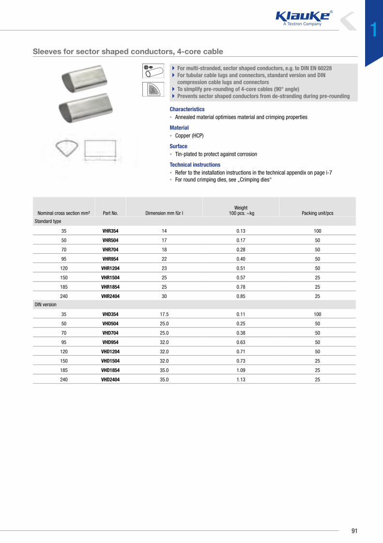
Nominal cross section mm² Part No. Dimension mm für lWeight
100 pcs. ~kg Packing unit/pcs
Standard type
35 VHR354 14 0.13 100
50 VHR504 17 0.17 50
70 VHR704 18 0.28 50
95 VHR954 22 0.40 50
120 VHR1204 23 0.51 50
150 VHR1504 25 0.57 25
185 VHR1854 25 0.78 25
240 VHR2404 30 0.85 25
DIN version
35 VHD354 17.5 0.11 100
50 VHD504 25.0 0.25 50
70 VHD704 25.0 0.38 50
95 VHD954 32.0 0.63 50
120 VHD1204 32.0 0.71 50
150 VHD1504 32.0 0.73 25
185 VHD1854 35.0 1.09 25
240 VHD2404 35.0 1.13 25
Sleeves for sector shaped conductors, 4-core cable
` For multi-stranded, sector shaped conductors, e.g. to DIN EN 60228` For tubular cable lugs and connectors, standard version and DIN
compression cable lugs and connectors` To simplify pre-rounding of 4-core cables (90° angle)` Prevents sector shaped conductors from de-stranding during pre-rounding
Characteristics▪ Annealed material optimises material and crimping properties
Material▪ Copper (HCP)
Surface▪ Tin-plated to protect against corrosion
Technical instructions▪ Refer to the installation instructions in the technical appendix on page i-7▪ For round crimping dies, see „Crimping dies“
91
1

Aluminium compression cable lugs and connectors to DINElectrical connection systems
RELIABLE - ALUMINIUM COMPRESSION CABLE LUGS AND CONNECTORS TO DINLight and extremely reliable: Klauke aluminium compression cable lugs are both.
Contact grease breaks down the oxidation layer, high-quality tinning facilitates the
contact with copper in dry environments. For the toughest demands, all cable lugs
and most cable lugs and connectors are IEC-tested for safety.
We offer a solution for practically every problem.
In brief
`` Aluminium cable lugs and connectors according to and based on DIN standards
`` Tested to the stringent IEC 61238-1
`` Appropriate solutions to 30 kV
`` Also for power lines and conductor wires
`` Tinned and non-tinned versions available
92

` Same excellent quality
Because we at Klauke have our own manufacturing facilities,
our products are always the same consistently high quality.
No matter which cable lug or connector you need, the Klauke
system guarantees you the best results.
◾ Constant qualities in many forms
◾ Connections according to or based on DIN standards
◾ Simple processing with DIN hexagonal crimping
or optionally EKM60ID
◾ Guaranteed safety through IEC 61238-1 tests
` Flexibility in power line construction
In power line construction too, Klauke products provide the
flexible and reliable solution.
For special solutions, contact us directly. We can make them
for you.
` Deep drawn
Deep-drawn connectors are produced with barrier and
precisely to DIN 46329. Thanks to the special production
method, there is absolutely no ingress or escaping of liquids
through the cable lug flange.
◾ Barrier design with oil stop
◾ Filled with contact grease as standard
◾ In the tinned version, also suitable for connecting to
copper in dry environments
◾ For moist environments, we recommend Klauke
connectors made from aluminium/copper
Code
Manufacturer’s mark
Ø hole
Cross-section
Narrow crimping
93
1
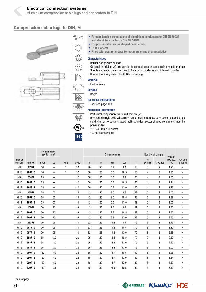
Electrical connection systemsAluminium compression cable lugs and connectors to DIN
Size of bolt dia. Part No.
Nominal cross section mm²
Hint Code
Dimension mm Number of crimpsWeight
100 pcs. ~kg
Packing unit/pcs rm/sm
se a b d1 d2 l
Al (7 mm) Al (wide)
M 8 263R8 16 -- * 12 30 20 5.8 8.4 50 4 2 1.20 4
M 10 263R10 16 -- * 12 30 20 5.8 10.5 50 4 2 1.20 4
M 8 264R8 25 -- 12 30 25 6.8 8.4 50 4 2 1.30 4
M 10 264R10 25 -- 12 30 25 6.8 10.5 50 4 2 1.24 4
M 12 264R12 25 -- 12 30 25 6.8 13.0 50 4 2 1.22 4
M 8 265R8 35 50 14 42 25 8.0 8.4 62 5 2 2.50 4
M 10 265R10 35 50 14 42 25 8.0 10.5 62 5 2 1.98 4
M 12 265R12 35 50 14 42 25 8.0 13.0 62 5 2 2.50 4
M 8 266R8 50 70 16 42 25 9.8 8.4 62 5 2 2.75 4
M 10 266R10 50 70 16 42 25 9.8 10.5 62 5 2 2.70 4
M 12 266R12 50 70 16 42 25 9.8 13.0 62 5 2 2.65 4
M 8 267R8 70 95 18 52 25 11.2 8.4 72 6 3 3.45 4
M 10 267R10 70 95 18 52 25 11.2 10.5 72 6 3 3.80 4
M 12 267R12 70 95 18 52 25 11.2 13.0 72 6 3 3.35 4
M 10 268R10 95 120 22 56 25 13.2 10.5 75 6 3 6.90 4
M 12 268R12 95 120 22 56 25 13.2 13.0 75 6 3 4.92 4
M 16 268R16 95 120 * 22 56 25 13.2 17.0 75 6 3 6.00 4
M 10 269R10 120 150 22 56 30 14.7 10.5 80 6 3 5.95 4
M 12 269R12 120 150 22 56 30 14.7 13.0 80 6 3 5.84 4
M 16 269R16 120 150 22 56 30 14.7 17.0 80 6 3 6.60 4
M 10 270R10 150 185 25 60 30 16.3 10.5 90 6 3 8.50 4
See next page
Compression cable lugs to DIN, Al
` For non-tension connections of aluminium conductors to DIN EN 60228 and aluminium cables to DIN EN 50182
` For pre-rounded sector shaped conductors` To DIN 46329` Filled with contact grease for optimum crimp characteristics
Characteristics▪ Barrier design with oil stop▪ Optional tin-plated (20 µm) version to connect copper bus bars in dry indoor areas▪ Simple and safe connection due to flat contact surfaces and internal chamfer▪ Unique tool assignment due to DIN die coding
Material▪ E-aluminium
Surface▪ Bright
Technical instructions▪ Tool: see page 103
Additional information▪ Part Number appendix for tinned version „V“▪ re = round single solid wire, rm = round multi-stranded, se = sector shaped single
solid wire, sm = sector shaped multi-stranded, sector shaped conductors must be pre-rounded
▪ 70 - 240 mm² UL-tested▪ * = not standardised
94

Size of bolt dia. Part No.
Nominal cross section mm²
Hint Code
Dimension mm Number of crimpsWeight
100 pcs. ~kg
Packing unit/pcs rm/sm
se a b d1 d2 l
Al (7 mm) Al (wide)
M 12 270R12 150 185 25 60 30 16.3 13.0 90 6 3 7.73 4
M 16 270R16 150 185 25 60 30 16.3 17.0 90 6 3 7.60 4
M 20 270R20 150 185 * 25 60 30 16.3 21.0 90 6 3 8.20 4
M 10 271R10 185 240 28 60 30 18.3 10.5 91 6 3 11.00 4
M 12 271R12 185 240 28 60 30 18.3 13.0 91 6 3 9.88 4
M 16 271R16 185 240 28 60 30 18.3 17.0 91 6 3 10.10 4
M 20 271R20 185 240 * 28 60 30 18.3 21.0 91 6 3 10.00 4
M 10 272R10 240 300 * 32 70 38 21.0 10.5 103 8 3 15.50 4
M 12 272R12 240 300 32 70 38 21.0 13.0 103 8 3 13.80 4
M 16 272R16 240 300 32 70 38 21.0 17.0 103 8 3 13.48 4
M 20 272R20 240 300 32 70 38 21.0 21.0 103 8 3 15.00 4
M 12 273R12 300 -- 34 70 38 23.3 13.0 103 8 3 17.60 1
M 16 273R16 300 -- 34 70 38 23.3 17.0 103 8 3 17.28 1
M 20 273R20 300 -- 34 70 38 23.3 21.0 103 8 3 17.40 1
M 12 274R12 400 -- 38 73 38 26.0 13.0 116 -- 4 38.00 1
M 16 274R16 400 -- 38 73 38 26.0 17.0 116 -- 4 37.40 1
M 20 274R20 400 -- 38 73 38 26.0 21.0 116 -- 4 40.20 1
M 12 275R12 500 -- 44 79 44 29.0 13.0 122 -- 4 43.70 1
M 16 275R16 500 -- 44 79 44 29.0 17.0 122 -- 4 43.30 1
M 20 275R20 500 -- 44 79 44 29.0 21.0 122 -- 4 43.00 1
Compression cable lugs to DIN, Al
95
1

Electrical connection systemsAluminium compression cable lugs and connectors to DIN
M 10204R10 25 -- 12 18 6.8 10.5 60 4 2 1.46 10
205R10 35 50 14 21 8.0 10.5 67 5 2 2.08 10
M 12 205R12 35 50 14 21 8.0 13.0 67 5 2 2.05 10
M 10 206R10 50 70 16 25 9.8 10.5 72 5 2 2.68 10
M 12 206R12 50 70 16 25 9.8 13.0 72 5 2 2.73 10
M 10 207R10 70 95 18 28 11.2 10.5 86 6 3 4.42 10
M 12 207R12 70 95 18 28 11.2 13.0 86 6 3 4.27 10
M 10 208R10 95 120 22 32 13.2 10.5 90 6 3 7.40 4
M 12 208R12 95 120 22 32 13.2 13.0 90 6 3 7.50 4
M 16 208R16 95 120 22 34 13.2 17.0 90 6 3 7.30 4
M 12 209R12 120 150 22 32 14.7 13.0 91 6 3 6.68 4
M 16 209R16 120 150 22 34 14.7 17.0 91 6 3 6.41 4
M 12 210R12 150 185 25 35 16.3 13.0 103 6 3 9.64 4
M 16 210R16 150 185 25 35 16.3 17.0 103 6 3 9.24 4
M 20 210R20 150 185 25 41 16.3 21.0 103 6 3 9.40 4
M 12 211R12 185 240 28 40 18.3 13.0 106 6 3 12.61 1
M 16 211R16 185 240 28 40 18.3 17.0 106 6 3 11.92 1
M 20 211R20 185 240 28 40 18.3 21.0 106 6 3 13.10 1
M 12 212R12 240 300 32 45 21.0 13.0 116 8 3 18.30 1
M 16 212R16 240 300 32 45 21.0 17.0 116 8 3 17.60 1
M 20 212R20 240 300 32 45 21.0 21.0 116 8 3 17.30 1
M 16 213R16 300 -- 34 49 23.3 17.0 124 8 3 17.50 1
M 20 213R20 300 -- 34 49 23.3 21.0 124 8 3 17.30 1
M 16 214R16 400 -- 38 58 26.0 17.0 165 -- 4 32.20 1
M 20 214R20 400 -- 38 58 26.0 21.0 165 -- 4 31.90 1
Size of bolt dia. Part No.
Nominal cross section mm²
Code
Dimension mm Number of crimps Weight 100 pcs.
~kgPacking unit/pcs rm/sm se b d1 d2 l Al (7 mm) Al (wide)
M 6 202R6 10 -- 10 16 5.0 6.5 52 4 2 0.86 25
M 8202R8 10 -- 10 18 5.0 8.5 52 4 2 0.88 25
203R8 16 -- 12 18 5.8 8.5 52 4 2 1.37 10
M 10 203R10 16 -- 12 18 5.8 10.5 52 4 2 1.39 10
M 8 204R8 25 -- 12 18 6.8 8.5 60 4 2 1.41 10
Compression cable lugs, Al
` For non-tension connections of aluminium conductors to DIN EN 60228 and aluminium cables to DIN EN 50182
` For pre-rounded sector shaped conductors` Tube dimension to DIN 46329` With code number for clear tool assignment` Filled with contact grease for optimum crimp characteristics
Characteristics▪ Easy to process due to crimp markings▪ Simple and safe connection due to flat contact surfaces and internal chamfer
Material▪ E-aluminium
Surface▪ Bright
Technical instructions▪ Tool: see page 103
Additional information▪ re = round single solid wire, rm = round multi-stranded, se = sector shaped single
solid wire, sm = sector shaped multi-stranded, sector shaped conductors must be pre-rounded
▪ 16 - 400 mm² IEC-tested
96

Part No.
Nominal cross section mm²
Hint Code
Dimension mm Number of crimps Weight 100 pcs.
~kgPacking unit/
pcs rm/sm se d1 l Al (7 mm) Al (wide)
222R 10 -- * 10 5.0 55 3/3 -- 0.95 10
223R 16 -- * 12 5.8 55 3/3 -- 1.40 10
224R 25 -- 12 6.8 70 4/4 2/2 1.60 10
225R 35 50 14 8.0 85 5/5 2/2 2.60 10
226R 50 70 16 9.8 85 5/5 2/2 3.20 10
227R 70 95 18 11.2 105 6/6 3/3 5.30 10
228R 95 120 22 13.2 105 6/6 3/3 7.60 10
229R 120 150 22 14.7 105 6/6 3/3 7.80 10
230R 150 185 25 16.3 125 6/6 3/3 10.70 10
231R 185 240 28 18.3 125 6/6 3/3 14.30 5
232R 240 300 32 21.0 145 8/8 3/3 20.30 5
233R 300 -- 34 23.3 145 8/8 3/3 22.20 1
234R 400 -- 38 26.0 210 -- 5/5 40.80 1
235R 500 -- 44 29.0 210 -- 5/5 56.00 1
Compression joint to DIN, Al
` For non-tension connections of aluminium conductors to DIN EN 60228 and aluminium cables to DIN EN 50182
` To DIN 46267, Part 2` With code number for clear tool assignment` Filled with contact grease for optimum crimp characteristics` For pre-rounded sector shaped conductors
Characteristics▪ Easy to process due to crimp markings▪ Simple cable entry due to internal chamfer▪ Simple and safe processing due to butt mark
Material▪ E-aluminium
Surface▪ Bright
Technical instructions▪ Tool: see page 103
Additional information▪ re = round single solid wire, rm = round multi-stranded, se = sector shaped single
solid wire, sm = sector shaped multi-stranded, sector shaped conductors must be pre-rounded
▪ 16 - 500 mm² IEC-tested▪ * = not standardised
97
1

Electrical connection systemsAluminium compression cable lugs and connectors to DIN
Part No.
Nominal cross section mm²
Code
Dimension mm Number of crimpsWeight
100 pcs. ~kgPacking unit/
pcs rm/sm se d1 l Al (7 mm) Al (wide)
Standard type
405R 35 50 14 8.20 90 4/4 2/2 2.7 10
406R 50 70 16 10.00 90 4/4 2/2 3.4 10
407R 70 95 18 11.50 95 4/4 2/2 4.6 10
408R 95 120 22 13.50 100 4/4 2/2 6.8 10
409R 120 150 22 15.00 105 4/4 2/2 7.4 10
410R 150 185 25 16.50 105 4/4 2/2 8.7 10
411R 185 240 28 18.50 125 5/5 2/2 13.4 5
412R 240 300 32 21.30 125 5/5 2/2 15.7 5
413R 300 -- 34 23.60 125 5/5 2/2 16.3 1
414R 400 -- 38 26.25 150 -- 3/3 25.8 1
Barrier version
415R 35 50 14 8.0 95 4/4 2/2 3.1 5
416R 50 70 16 9.8 95 4/4 2/2 5.6 5
417R 70 95 18 11.2 100 4/4 2/2 6.1 5
418R 95 120 22 13.2 105 4/4 2/2 9.2 5
419R 120 150 22 14.7 110 4/4 2/2 10.3 5
420R 150 185 25 16.3 110 4/4 2/2 12.0 5
421R 185 240 28 18.3 130 5/5 2/2 15.6 5
422R 240 300 32 21.0 130 5/5 2/2 19.1 5
423R 300 -- 34 23.3 135 5/5 2/2 30.7 1
424R 400 -- 38 26.0 165 -- 3/3 30.0 1
Compression joints, Al
` For non-tension connections of medium-voltage aluminium cable 10-30 kV` For non-tension connections of aluminium conductors to DIN EN 60228
and aluminium cables to DIN EN 50182 and pre-rounded sector shaped conductors
` Tube dimension to DIN 46267, Part 2` With code number for clear tool assignment` Filled with contact grease for optimum crimp characteristics
Characteristics▪ Also available as barrier design with oil stop▪ With chamfered edges for reduced wrapping during assembly▪ Easy to process due to crimp markings▪ Simple cable entry due to internal chamfer
Material▪ E-aluminium
Surface▪ Bright
Technical instructions▪ Tool: see page 103
Additional information▪ re = round single solid wire, rm = round multi-stranded, se = sector shaped single
solid wire, sm = sector shaped multi-stranded, sector shaped conductors must be pre-rounded
98

Part No.
Nominal cross section mm²
Code
Dimension mm Number of crimps Weight 100 pcs.
~kgPacking unit/pcsvon auf d1 d2 l Al (7 mm) Al (wide)
425R25 35 25 14 8.0 6.8 95 4/4 2/2 2.800 5
426R35 50 35 16 9.8 8.0 95 4/4 2/2 3.450 5
427R35 70 35 18 11.2 8.0 100 4/4 2/2 4.790 5
427R50 70 50 18 11.2 9.8 100 4/4 2/2 4.420 5
428R50 95 50 22 13.2 9.8 105 4/4 2/2 7.600 5
428R70 95 70 22 13.2 11.2 105 4/4 2/2 7.350 5
429R70 120 70 22 14.7 11.2 110 4/4 2/2 7.100 5
429R95 120 95 22 14.7 13.2 110 4/4 2/2 6.550 5
430R70 150 70 25 16.3 11.2 110 4/4 2/2 9.800 5
430R95 150 95 25 16.3 13.2 110 4/4 2/2 9.500 5
430R120 150 120 25 16.3 14.7 110 4/4 2/2 8.650 5
431R70 185 70 28 18.3 11.2 130 -- 2/2 15.050 5
431R95 185 95 28 18.3 13.2 130 -- 2/2 14.400 5
431R120 185 120 28 18.3 14.7 130 5/5 2/2 13.700 5
431R150 185 150 28 18.3 16.3 130 5/5 2/2 13.050 5
432R120 240 120 32 21.0 14.7 130 -- 2/2 18.800 5
432R150 240 150 32 21.0 16.3 130 5/5 2/2 18.125 5
432R185 240 185 32 21.0 18.3 130 5/5 2/2 17.275 5
433R150 300 150 34 23.3 16.3 135 5/5 2/2 21.100 1
433R185 300 185 34 23.3 18.3 135 5/5 2/2 20.120 1
433R240 300 240 34 23.3 21.0 135 5/5 2/2 18.730 1
434R300 400 300 38 26.0 23.3 165 -- 3/3 31.200 1
Reduction compression joints, Al, barrier type
` For non-tension connections of aluminium conductors to DIN EN 60228 and aluminium cables to DIN EN 50182
` In nominal cross-section area tube dimension to DIN 46267, part 2` For pre-rounded sector shaped conductors` Ideal for connecting differing conductor cross-sections` Filled with contact grease for optimum crimp characteristics
Characteristics▪ Barrier design with oil stop▪ Unique tool assignment due to DIN die coding▪ Easy to process due to crimp markings▪ Simple cable entry due to internal chamfer
Material▪ E-aluminium
Surface▪ Bright
Technical instructions▪ Tools: see chart page 103
Additional information▪ re = round single solid wire, rm = round multi-stranded, se = sector shaped single
solid wire, sm = sector shaped multi-stranded, sector shaped conductors must be pre-rounded
99
1

Electrical connection systemsAluminium compression cable lugs and connectors to DIN
Part No.
Nominal cross section mm²
Code
Dimension mm Number of crimps Weight 100 pcs.
~kgPacking unit/pcs von auf d1 d2 l Al (7 mm) Al (wide)
284R16 25 16 12 7.0 5.8 75 4/4 2/2 1.53 10
285R25 35 25 14 8.2 6.8 90 5/5 2/2 2.50 10
286R25 50 25 16 10.0 6.8 90 5/5 2/2 3.24 10
286R35 50 35 16 10.0 8.0 90 5/5 2/2 3.09 10
287R25 70 25 18 11.5 6.8 110 6/6 3/3 5.50 10
287R35 70 35 18 11.5 8.0 110 6/6 3/3 5.35 10
287R50 70 50 18 11.5 9.8 110 6/6 3/3 4.96 10
288R25 95 25 22 13.5 6.8 110 6/6 3/3 9.10 10
288R35 95 35 22 13.5 8.0 110 6/6 3/3 8.90 10
288R50 95 50 22 13.5 9.8 110 6/6 3/3 8.51 10
288R70 95 70 22 13.5 11.2 110 6/6 3/3 8.15 10
289R50 120 50 22 15.0 9.8 110 6/6 3/3 8.04 10
289R70 120 70 22 15.0 11.2 110 6/6 3/3 7.66 10
289R95 120 95 22 15.0 13.2 110 6/6 3/3 7.14 10
290R70 150 70 25 16.5 11.2 130 6/6 3/3 11.70 10
290R95 150 95 25 16.5 13.2 130 6/6 3/3 11.05 10
290R120 150 120 25 16.5 14.7 130 6/6 3/3 10.49 10
291R120 185 120 28 18.5 14.7 130 6/6 3/3 13.80 5
291R150 185 150 28 18.5 16.3 130 6/6 3/3 13.19 5
292R95 240 95 32 21.3 13.2 150 -- 3/3 22.24 5
292R120 240 120 32 21.3 14.7 150 -- 3/3 21.59 5
292R150 240 150 32 21.3 16.3 150 -- 3/3 20.87 5
Reduction-compression joints, Al
` For non-tension connections of aluminium conductors to DIN EN 60228 and aluminium cables to DIN EN 50182
` For pre-rounded sector shaped conductors` In nominal cross-section area tube dimension to DIN 46267, part 2` With code number for clear tool assignment` Filled with contact grease for optimum crimp characteristics
Characteristics▪ For connecting different conductor cross-sections▪ Easy to process due to crimp markings▪ Simple cable entry due to internal chamfer
Material▪ E-aluminium
Surface▪ Bright
Technical instructions▪ Tool: see page 103
Additional information▪ re = round single solid wire, rm = round multi-stranded, se = sector shaped single
solid wire, sm = sector shaped multi-stranded, sector shaped conductors must be pre-rounded
100

Nominal cross
section mm²Part No. Hint Code
Dimension mm Number of crimpsConductor mm dia.
Weight 100 pcs.
~kgPacking unit/pcsd1 d4 l Al (7 mm) Al (wide)
16 243R * 12 5.8 12.0 140 8/8 4/4 5.1 3.4 10
25 244R 12 6.8 12.0 140 8/8 4/4 6.3 2.9 10
35 245R 14 8.0 14.0 140 8/8 4/4 7.5 3.9 10
50 246R 16 10.0 16.0 155 8/8 4/4 9.0 5.2 10
70 247R 18 11.5 18.5 165 8/8 4/4 10.5 7.4 10
95 248R 22 13.5 22.0 165 8/8 4/4 12.5 12.2 10
120 249R 25 15.5 25.5 250 12/12 6/6 14.0 21.8 10
150 250R 28 16.5 28.5 300 -- 7/7 15.7 34.4 10
185 251R 28 18.5 28.5 330 -- 7/7 17.5 33.0 5
240 252R 34 21.5 34.5 350 -- 7/7 20.2 54.0 5
300 253R 38 23.5 38.5 400 -- 8/8 22.5 79.0 1
Compression joint to DIN, Al, full tension
` For full tension connections of aluminium cables to DIN EN 50182` To DIN 48085, Part 2` With code number for clear tool assignment` Filled with contact grease for optimum crimp characteristics
Characteristics▪ Easy to process due to crimp markings▪ Simple cable entry due to internal chamfer
Material▪ E-aluminium to 95 mm²▪ AlMgSi from 120 mm²
Surface▪ Bright
Technical instructions▪ Tool: see page 103
Additional information▪ * = not standardised
101
1

Electrical connection systemsAluminium compression cable lugs and connectors to DIN
Nominal cross section mm²
Part No. Code
Dimension mm Number of crimpsConductor mm dia.
Weight 100 pcs. ~kg
Packing unit/pcs d1 l Aldrey (7 mm) Aldrey (wide)
35 295AD 14 8.0 140 8/8 -- 7.5 4.7 5
50 296AD 16 10.0 155 8/8 -- 9.0 5.9 5
70 297AD 18 11.5 165 8/8 -- 10.5 9.0 5
Nominal cross
section mm²
Part No. Code
Dimension mm
Code Al
Number of crimps
Conductor mm dia.
Weight 100 pcs.
~kgPacking unit/pcsd41 d42 l1 l2
Stahl (5 mm)
Stahl (wide)
Al (7 mm) Al (wide)
35 - 6 455R 6 14.0 6.3 235 75 14 5/5 -- 8/8 -- 8.1 7 5
50 - 8 456R 7 16.0 7.5 270 95 16 6/6 -- 9/9 -- 9.6 11 5
70 - 12 457R 9 18.5 9.5 270 95 18 6/6 -- 9/9 -- 11.7 15 5
95 - 15 458R 9 22.5 9.6 310 95 22 6/6 -- 11/11 -- 13.6 23 5
120 - 20 459R 13 25.0 13.0 380 110 25 7/7 4/4 13/13 6/6 15.5 36 5
Compression joints, Al, full tension
` For full tension connections of Aldrey cables according to DIN EN 50182` With code number for clear tool assignment` Filled with contact grease for optimum crimp characteristics
Characteristics▪ Tube diameters adjusted to Aldrey cables▪ Easy to process due to crimp markings
Material▪ AlMgSi F20
Surface▪ Bright
Technical instructions▪ Tool: see page 103
Compression joint to DIN, Al/St
` For full tension connections of Al/St conductors to DIN EN 50182` To DIN 48085, Part 3` Unique tool assignment due to coding` Filled with contact grease for optimum crimp characteristics
Characteristics▪ Easy to process due to crimp markings▪ Simple cable entry due to internal chamfer
Material▪ Sleeve: E-aluminium▪ Sleeve: Steel (St 52)
Surface▪ Al sleeve: bright▪ St sleeve: hot zinc galvanised
Technical instructions▪ Tool: see page 105
102
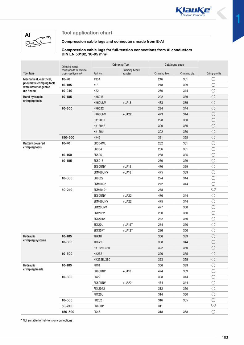
Mechanical, electrical, pneumatic crimping tools with interchangeable die / head
10-70 K354 246 331
10-185 K18 248 339
10-240 K22 250 344
Hand hydraulic crimping tools
10-185 HK6018 292 339
HK60UNV +UA18 473 339
10-300 HK6022 294 344
HK60UNV +UA22 473 344
HK12030 298 350
HK12042 300 350
HK120U 302 350
150-500 HK45 321 358
Battery powered crimping tools
10-70 EK354ML 262 331
EK354 266 331
10-150 EK505 268 335
10-185 EK5018 270 339
EK60UNV +UA18 476 339
EKM60UNV +UA18 475 339
10-300 EK6022 274 344
EKM6022 272 344
50-240 EKM60ID* 278
EK60UNV +UA22 476 344
EKM60UNV +UA22 475 344
EK120UNV 477 350
EK12032 280 350
EK12042 282 350
EK120U +UA15T 284 350
EK135FT +UA12T 286 350
Hydraulic crimping systems
10-185 THK18 306 339
10-300 THK22 308 344
HK122EL380 322 350
10-500 HK252 320 355
HK252EL380 323 355
Hydraulic crimping heads
10-185 PK18 306 339
PK60UNV +UA18 474 339
10-300 PK22 308 344
PK60UNV +UA22 474 344
PK12042 312 350
PK120U 314 350
10-500 PK252 316 355
50-240 PK60ID* 311
150-500 PK45 318 358
Tool application chart
Compression cable lugs and connectors made from E-Al
Compression cable lugs for full-tension connections from Al conductors DIN EN 50182, 16-95 mm²
* Not suitable for full-tension connections
Tool type
Crimping range corresponds to nominal cross-section mm²
Crimping Tool Catalogue page
Crimp profilePart No.Crimping head / adapter Crimping Tool Crimping die
103
1

Aldrey
Electrical connection systemsAluminium compression cable lugs and connectors to DIN
Mechanical, electrical, pneumatic crimping tools with interchangeable die / head
25-50 K354 246 331
25-95 K18 248 339
25-185 K22 250 344
Hand hydraulic crimping tools
25-95 HK6018 292 339
HK60UNV +UA18 473 339
25-185 HK6022 294 344
HK60UNV +UA22 473 344
HK12030 298 350
HK12042 300 350
HK120U 302 350
150-300 HK45 321 358
Battery powered crimping tools
25-50 EK354ML 262 331
EK354 266 331
25-95 EK505 268 335
EK5018 270 339
EK60UNV +UA18 476 339
EKM60UNV +UA18 475 339
25-185 EK6022 274 344
EKM6022 272 344
EK60UNV +UA22 476 344
EKM60UNV +UA22 475 344
EK12032 280 350
EK12042 282 350
EK120U 284 350
EK135FT +UA15T 286 350
EK120UNV +UA12T 477 350
Hydraulic crimping systems
25-95 THK18 306 339
25-185 THK22 308 344
HK122EL380 322 350
25-300 HK252 320 355
HK252EL380 323 355
Hydraulic crimping heads
25-95 PK18 306 339
PK60UNV +UA18 474 339
25-185 PK22 308 344
PK60UNV +UA22 474 344
PK12042 312 350
PK120U 314 350
25-300 PK252 316 355
150-300 PK45 318 358
Tool application chart
Compression joints for full-tension connections from Aldrey conductors to DIN EN 50182 and Al conductors to DIN EN 50182, 120-300 mm²
Tool type
Crimping range corresponds to nominal cross-section mm²
Crimping Tool Catalogue page
Crimp profilePart No.Crimping head / adapter Crimping Tool Crimping die
104

Mechanical, electrical, pneumatic crimping tools with interchangeable die / head
25/4-120/20 K22 250 345
Hand hydraulic crimping tools
25/4-120/20 HK6022 294 345
HK60UNV +UA22 473 345
HK12030 298 350
HK12042 300 350
HK120U 302 350
Battery powered crimping tools
25/4-120/20 EK6022 274 345
EKM6022 272 345
EK60UNV +UA22 476 345
EKM60UNV +UA22 475 345
EK12032 280 350
EK12042 282 350
EK120U 284 350
EK135FT +UA15T 286 350
EK120UNV +UA12T 477 350
Hydraulic crimping systems
25/4-120/20 THK22 308 345
HK122EL380 322 350
HK252 320 356
HK252EL380 323 356
Hydraulic crimping heads
25/4-120/20 PK22 308 345
PK60UNV +UA22 474 345
PK12042 312 350
PK120U 314 350
PK252 316 356
Tool application chart
Compression joints for non-tension connections from Al/St. cables and full-tension connections to DIN 48085, part 3 for Al/St. cables to DIN EN 50182
Tool type
Crimping range corresponds to nominal cross-section mm²
Crimping Tool Catalogue page
Crimp profilePart No.Crimping head / adapter Crimping Tool Crimping die
105
1

Electrical connection systems
CONNECTED - COMPRESSION CABLE LUGS MADE FROM ALUMINIUM AND COPPERTwo components reliably connected. Copper and aluminium have different material
properties. That’s not always a good thing. Our compression cable lugs and connectors
made from aluminium and copper are intricately produced by special processes and
join together what belongs together. No matter which material you use: Your contacts
are reliable with Klauke.
In brief
`` Simple processing based on DIN standards
`` Reliable connection of copper and aluminium, even in contact with water
`` Special manufacturing methods ensure high quality
`` Also suitable for sector shaped conductors and wires
Aluminium/copper compression cable lugs and connectors
106

` Numerous versions available
The great thing about the broad Klauke range is: You can
select the suitable cable lug for your project and optimally
process your choice using the Klauke tools. Everything fitting
together.
◾ Processing as usual with standard aluminium cable lugs
◾ Different versions available, for instance, as a cable lug with
a copper eye or Cupal washers or as a rotational friction
welded cable lug
` Well connected in every situation
Reduction compression joints enable aluminium conductors to
be integrated into copper-containing systems. They connect
the two different materials regardless of the physical cable
dimensions.
◾ Suitable for round or sector shaped conductors
◾ Suitable for multi-stranded and single-stranded sector
shaped conductors
` As good as always
Cable lugs and connectors made from aluminium and copper
can be processed in exactly the same way as DIN standard
aluminium cable lugs. No special tools are required, you
simply use the right Klauke dies. And so the result is as good
as always.
◾ For round and sector shaped conductors to DIN EN 60228
and aluminium wires to DIN 50182
◾ No additional costs for new crimping dies
◾ Reliable connection by preventing contact corrosion
107
1

Electrical connection systems
Size of bolt dia. Part No.
Nominal cross section mm²
Code
Dimension mm Number of crimps Weight 100 St.
~kg Cu
Weight 100 St.
~kg total
Packing unit/pcsrm/sm se b d1 d2 l
Al (7 mm) Al (wide)
M 8 363R8 16 12 25 6.0 8.5 67.5 4 2 4.4 5.9 10
M 10 363R10 16 12 25 6.0 10.5 67.5 4 2 4.2 5.7 10
M 8 364R8 25 12 25 6.8 8.5 67.5 4 2 4.4 5.8 10
M 10 364R10 25 12 25 6.8 10.5 67.5 4 2 4.2 5.6 10
M 12 364R12 25 12 25 6.8 13.0 67.5 4 2 3.9 5.3 10
M 8 365R8 35 50 14 25 8.0 8.5 76.5 5 2 4.4 6.3 10
M 10 365R10 35 50 14 25 8.0 10.5 76.5 5 2 4.2 6.1 10
M 12 365R12 35 50 14 25 8.0 13.0 76.5 5 2 3.8 5.8 10
M 8 366R8 50 70 16 25 9.8 8.5 76.5 5 2 4.4 6.4 10
M 10 366R10 50 70 16 25 9.8 10.5 76.5 5 2 4.2 6.2 10
M 12 366R12 50 70 16 25 9.8 13.0 76.5 5 2 3.9 5.9 10
M 10 367R10 70 95 18 25 11.2 10.5 84.5 6 3 4.2 7.4 10
M 12 367R12 70 95 18 25 11.2 13.0 84.5 6 3 3.9 7.1 10
M 10 368R10 95 120 22 30 13.2 10.5 90.5 6 3 7.4 11.4 10
M 12 368R12 95 120 22 30 13.2 13.0 90.5 6 3 6.8 10.8 10
M 16 368R16 95 120 22 30 13.2 17.0 90.5 6 3 6.4 10.4 10
M 12 369R12 120 150 22 30 14.7 13.0 92.0 6 3 6.8 11.4 5
M 16 369R16 120 150 22 30 14.7 17.0 92.0 6 3 6.4 10.8 5
M 12 370R12 150 185 25 30 16.3 13.0 104.0 6 3 6.8 13.1 5
M 16 370R16 150 185 25 30 16.3 17.0 104.0 6 3 6.4 12.7 5
M 20 370R20 150 185 25 35 16.3 21.0 107.5 6 3 10.1 16.4 5
M 10 371R10 185 240 28 30 18.3 10.5 105.0 6 3 10.3 18.6 5
M 12 371R12 185 240 28 35 18.3 13.0 105.0 6 3 10.1 18.4 5
M 16 371R16 185 240 28 30 18.3 17.0 105.0 6 3 9.3 17.6 5
see next page
Compression cable lugs, Al/Cu
` Tube dimension to DIN 46329` For non-tension connections of Al cables to DIN EN 60228 and aluminium
cables to DIN EN 50182 as well as pre-rounded sector shaped conductors` For connecting aluminium connections to copper rails in humid areas` With code number for clear tool assignment` Filled with contact grease for optimum crimp characteristics
Characteristics▪ Barrier design with oil stop and solid copper palm▪ Easy to process due to crimp markings▪ Internal chamfer for simple cable insertion
Suitable for▪ Pre-rounded sector shaped conductors
Material▪ E-aluminium▪ Copper (EN13600)
Surface▪ Bright
Technical instructions▪ Tool: see page 115
Additional information▪ re = round single solid wire, rm = round multi-stranded, se = sector shaped single solid
wire, sm = sector shaped multi-stranded, sector shaped conductors must be pre-rounded
Aluminium/copper compression cable lugs and connectors
108

Size of bolt dia. Part No.
Nominal cross section mm²
Code
Dimension mm Number of crimps Weight 100 St.
~kg Cu
Weight 100 St.
~kg total
Packing unit/pcsrm/sm se b d1 d2 l Al (7 mm) Al (wide)
M 20 371R20 185 240 28 35 18.3 21.0 107.5 6 3 10.1 18.4 5
M 10 372R10 240 300 32 35 21.0 10.5 118.5 8 3 12.1 22.5 5
M 12 372R12 240 300 32 35 21.0 13.0 118.5 8 3 11.8 22.2 5
M 16 372R16 240 300 32 35 21.0 17.0 118.5 8 3 11.0 21.4 5
M 20 372R20 240 300 32 35 21.0 21.0 118.5 8 3 10.1 20.5 5
M 12 373R12 300 -- 34 40 23.3 13.0 123.5 8 3 17.7 33.7 2
M 16 373R16 300 -- 34 40 23.3 17.0 123.5 8 3 16.9 32.9 2
M 20 373R20 300 -- 34 40 23.3 21.0 123.5 8 3 16.0 32.0 1
M 12 374R12 400 -- 38 40 26.0 13.0 150.5 -- 4 25.6 37.4 1
Size of bolt dia. Part No.
Nominal cross section mm²
Code
Dimension mm Number of crimps Weight 100 St.
~kg Cu
Weight 100 St.
~kg total
Packing unit/pcsrm/sm se b d1 d2 l
Cu (5 mm) Cu (wide)
M 6 302R6 10 -- 10 18 5.0 6.5 52 4 2 0.260 1.20 10
M 8302R8 10 -- 10 22 5.0 8.5 52 4 2 0.580 1.50 10
303R8 16 25 12 22 5.8 8.5 52 4 2 0.600 1.95 10
M 10 303R10 16 25 12 25 5.8 10.5 52 4 2 0.600 2.00 10
M 8 304R8 25 35 12 22 6.8 8.5 60 4 2 0.625 2.00 10
M 10304R10 25 35 12 25 6.8 10.5 60 4 2 0.900 2.10 10
305R10 35 50 14 26 8.0 10.5 67 5 2 0.800 3.00 10
M 12 305R12 35 50 14 30 8.0 13.0 67 5 2 1.120 3.10 10
M 10 306R10 50 70 16 27 9.8 10.5 72 5 2 0.900 3.60 10
M 12 306R12 50 70 16 30 9.8 13.0 72 5 2 1.120 3.80 10
M 10 307R10 70 95 18 29 11.2 10.5 86 6 3 1.075 5.60 10
see next page
Compression cable lugs, Al/Cu
Compression cable lugs, Al/Cu with Cu eye
` For non-tension connections of aluminium conductors to DIN EN 60228 and aluminium cables to DIN EN 50182
` Tube dimension to DIN 46329` For pre-rounded sector shaped conductors` Unique tool assignment due to coding` Filled with contact grease for optimum crimp characteristics
Characteristics▪ For connecting non-tension aluminium connections using Cu-washers in humid
areas▪ With Cu eyelet in screw-on area▪ Easy to process due to crimp markings▪ Simple cable entry due to internal chamfer
Material▪ E-aluminium▪ Copper (EN13600)
Surface▪ Bright
Technical instructions▪ Tool: see page 115
Additional information▪ re = round single solid wire, rm = round multi-stranded, se = sector shaped single solid
wire, sm = sector shaped multi-stranded, sector shaped conductors must be pre-rounded
109
1

Electrical connection systems
Size of bolt dia. Part No.
Nominal cross section mm²
Code
Dimension mm Number of crimps Weight 100 St.
~kg Cu
Weight 100 St.
~kg total
Packing unit/pcsrm/sm se b d1 d2 l
Cu (5 mm) Cu (wide)
M 12 307R12 70 95 18 32 11.2 13.0 86 6 3 1.300 5.70 10
M 10 308R10 95 120 22 32 13.2 10.5 90 6 3 1.435 10.00 5
M 12 308R12 95 120 22 35 13.2 13.0 90 6 3 1.735 9.50 5
M 16 308R16 95 120 22 38 13.2 17.0 90 6 3 2.655 10.00 5
M 12 309R12 120 150 22 35 14.7 13.0 91 6 3 1.810 8.70 5
M 16 309R16 120 150 22 38 14.7 17.0 91 6 3 2.230 8.80 5
M 12 310R12 150 185 25 35 16.3 13.0 103 6 3 2.025 12.20 5
M 16 310R16 150 185 25 41 16.3 17.0 103 6 3 2.655 12.30 5
M 20 310R20 150 185 25 44 16.3 21.0 103 6 3 3.620 12.80 5
M 12 311R12 185 240 28 40 18.3 13.0 106 6 3 2.320 15.00 5
M 16 311R16 185 240 28 42 18.3 17.0 106 6 3 4.975 15.50 5
M 20 311R20 185 240 28 46 18.3 21.0 106 6 3 4.610 15.50 5
M 12 312R12 240 300 32 45 21.0 13.0 116 8 3 2.750 20.00 5
M 16 312R16 240 300 32 45 21.0 17.0 116 8 3 3.400 21.00 5
M 20 312R20 240 300 32 49 21.0 21.0 116 8 3 4.600 22.00 5
M 16 313R16 300 -- 34 51 23.3 17.0 124 8 3 3.980 21.60 1
M 20 313R20 300 -- 34 51 23.3 21.0 124 8 3 5.510 22.20 1
M 16 314R16 400 -- 38 58 26.0 17.0 165 -- 4 4.200 35.00 1
M 20 314R20 400 -- 38 58 26.0 21.0 165 -- 4 5.950 35.00 1
Aluminium/copper compression cable lugs and connectors
Compression cable lugs, Al/Cu with Cu eye
110

Part No.
Nominal cross section mm² Dimension mm CodeWeight 100 St.
~kg Cu
Weight 100 St.
~kg total
Packing unit/pcsrm/sm Al se Cu rm/sm l Al Cu Al Cu
322R10 10 16 10 55.0 5.0 4.5 10 6 0.212 1.100 4
322R16 10 16 16 61.0 5.0 5.4 10 8 0.714 1.550 4
323R10 16 25 10 55.0 6.0 4.5 12 6 0.212 1.500 4
323R16 16 25 16 61.0 6.0 5.4 12 8 0.714 1.750 4
324R10 25 35 10 55.0 6.8 4.5 12 6 0.212 1.400 4
324R16 25 35 16 61.0 6.8 5.5 12 8 0.714 1.650 4
324R25 25 35 25 61.0 6.8 7.0 12 10 0.892 1.900 4
324R35 25 35 35 61.0 6.8 8.2 12 12 1.624 2.000 4
324R50 25 35 50 72.0 6.8 10.0 12 14 2.362 3.500 4
324R416 25/4 35 16 61.0 7.6 5.5 12 8 0.714 1.600 4
324R425 25/4 35 25 61.0 7.6 7.0 12 10 0.892 1.850 4
325R16 35 50 16 71.0 8.0 5.5 14 8 0.714 2.500 4
325R25 35 50 25 71.0 8.0 7.0 14 10 0.892 2.650 4
325R35 35 50 35 71.0 8.0 8.2 14 12 1.519 3.300 4
325R50 35 50 50 77.0 8.0 10.0 14 14 2.362 3.530 4
325R616 35/6 50 16 71.0 9.0 5.5 14 8 0.714 2.450 4
325R625 35/6 50 25 71.0 9.0 7.0 14 10 0.892 2.600 4
325R635 35/6 50 35 71.0 9.0 8.2 14 12 1.624 3.250 4
326R16 50 70 16 71.5 9.8 5.5 16 8 0.714 2.850 4
326R25 50 70 25 71.5 9.8 7.0 16 10 0.892 3.200 4
326R35 50 70 35 71.5 9.8 8.2 16 12 1.624 3.800 4
326R50 50 70 50 77.5 9.8 10.0 16 14 2.362 4.550 4
327R16 70 95 16 79.0 11.2 5.5 18 8 0.714 4.100 4
see next page
Compression joints, Al/Cu
` For non-tension connections of aluminium conductors to DIN EN 60228 and aluminium cables to DIN EN 50182
` For Cu round conductors, e.g. to DIN EN 60228 Cl. 1, 2, 5 and 6` For non-tension copper cables, to DIN 48201` Tube dimensions to DIN 46267, part 1 and 2 and pre-rounded sector shaped
conductors` Unique tool assignment due to coding
Characteristics▪ For connecting non-tension aluminium and copper connections▪ Easy to process due to crimp markings▪ Simple cable entry due to internal chamfer
Material▪ E-aluminium▪ Copper (EN13600)
Surface▪ Bright
Technical instructions▪ Sleeves for compacted conductors and sleeves for 3-core and 4-core cables, see
chapter „Sleeves for compacted conductors and sector shaped conductors - Cu“▪ Reduction sleeves for connecting unequal cross-sections can be found on page 68▪ Tool: see page 115
Additional information▪ re = round single solid wire, rm = round multi-stranded, se = sector shaped single
solid wire, sm = sector shaped multi-stranded, sector shaped conductors must be pre-rounded
111
1

Electrical connection systems
Part No.
Nominal cross section mm² Dimension mm CodeWeight 100 St.
~kg Cu
Weight 100 St.
~kg total
Packing unit/pcsrm/sm Al se Cu rm/sm l Al Cu Al Cu
327R25 70 95 25 79.0 11.2 7.0 18 10 0.892 3.950 4
327R35 70 95 35 79.0 11.2 8.2 18 12 1.624 4.900 4
327R50 70 95 50 85.0 11.2 10.0 18 14 2.362 5.700 4
327R70 70 95 70 86.0 11.2 11.5 18 16 2.921 7.250 4
327R95 70 95 95 95.0 11.2 13.5 18 18 4.957 9.360 4
327R120 70 95 120 99.0 11.2 15.5 18 20 5.640 10.540 4
328R16 95 120 16 79.0 13.2 5.5 22 8 0.714 6.150 4
328R25 95 120 25 79.0 13.2 7.0 22 10 0.892 6.300 4
328R35 95 120 35 79.0 13.2 8.2 22 12 1.519 6.800 4
328R50 95 120 50 85.0 13.2 10.0 22 14 2.362 8.050 4
328R70 95 120 70 87.0 13.2 11.5 22 16 3.105 8.200 4
328R95 95 120 95 95.0 13.2 13.5 22 18 4.957 10.350 4
328R120 95 120 120 95.0 13.2 15.5 22 20 5.640 11.550 4
329R35 120 150 35 81.0 14.7 8.2 22 12 1.519 7.600 4
329R50 120 150 50 87.0 14.7 10.0 22 14 2.362 7.900 4
329R70 120 150 70 89.0 14.7 11.5 22 16 3.105 8.500 4
329R95 120 150 95 97.0 14.7 13.5 22 18 4.857 11.000 4
329R120 120 150 120 97.0 14.7 15.5 22 20 5.640 10.280 4
330R16 150 185 16 91.5 16.3 5.4 25 8 0.714 7.800 4
330R25 150 185 25 91.5 16.3 6.8 25 10 0.892 8.000 4
330R35 150 185 35 91.5 16.3 8.2 25 12 1.624 8.400 4
330R50 150 185 50 98.5 16.3 10.0 25 14 2.362 10.200 4
330R70 150 185 70 99.5 16.3 11.5 25 16 3.105 10.350 4
330R95 150 185 95 107.5 16.3 13.5 25 18 4.957 12.650 4
330R120 150 185 120 107.5 16.3 15.5 25 20 5.640 13.900 4
330R150 150 185 150 124.0 16.3 17.0 25 22 8.231 16.700 4
331R50 185 240 50 99.0 18.3 10.0 28 14 2.362 12.100 1
331R70 185 240 70 100.0 18.3 11.5 28 16 3.105 13.000 1
331R95 185 240 95 108.0 18.3 13.5 28 18 4.957 14.450 1
331R120 185 240 120 108.0 18.3 15.5 28 20 5.640 13.720 1
331R150 185 240 150 113.0 18.3 17.0 28 22 8.231 19.550 1
331R185 185 240 185 116.0 18.3 19.0 28 25 9.621 21.000 1
332R50 240 300 50 110.0 21.0 10.0 32 14 2.362 16.500 1
332R70 240 300 70 111.0 21.0 11.5 32 16 3.105 18.000 1
332R95 240 300 95 119.0 21.0 13.5 32 18 4.957 19.000 1
332R120 240 300 120 119.0 21.0 15.5 32 20 5.640 20.500 1
332R150 240 300 150 124.0 21.0 17.0 32 22 8.231 23.300 1
332R185 240 300 185 127.0 21.0 19.0 32 25 9.621 25.500 1
332R240 240 300 240 128.0 21.0 21.5 32 28 12.705 30.100 1
333R120 300 -- 120 119.0 23.5 15.5 34 20 5.640 27.800 1
333R150 300 -- 150 124.0 23.5 17.0 34 22 8.234 31.100 1
333R185 300 -- 185 127.0 23.5 19.0 34 25 9.621 32.700 1
333R240 300 -- 240 128.0 23.5 21.5 34 28 12.705 37.500 1
333R300 300 -- 300 134.0 23.5 24.5 34 32 16.099 41.700 1
Aluminium/copper compression cable lugs and connectors
Compression joints, Al/Cu
112

Part No.
Nominal cross section mm²
Code
Dimension mmBolt mm
dia.Conductor mm dia.
Weight 100 St.
~kg Cu
Weight 100 St.
~kg total
Packing unit/pcsrm/sm se d Ø d1 l l1
344R 25 35 12 12.0 6.8 58 20 6 6.3 0.462 1.6 10
345R 35 50 14 14.0 8.0 71 22 7 7.5 0.695 2.5 10
346R 50 70 16 16.0 10.0 74 25 8 9.0 1.037 3.3 10
347R 70 95 18 18.5 11.5 87 30 10 10.5 1.958 5.4 10
348R 95 120 22 23.0 13.2 91 33 12 12.5 3.112 8.7 10
349R 120 150 22 23.0 15.0 97 38 12 14.0 3.598 9.0 10
350R 150 185 25 25.5 16.5 108 38 12 15.8 3.598 10.9 10
351R 185 240 28 28.5 18.5 116 44 14 17.5 3.692 15.7 5
352R 240 300 32 32.5 21.5 128 44 16 20.3 7.435 21.8 5
353R 300 -- 34 34.5 23.5 131 46 18 22.5 9.410 26.7 1
Compression joints with Cu bolts, Al
` For non-tension connections of aluminium conductors to DIN EN 60228 and aluminium cables to DIN EN 50182
` For pre-rounded sector shaped conductors` Tube dimension to DIN 46267, part 2` Unique tool assignment due to coding
Characteristics▪ For connecting non-tension Al connections in Cu clamps▪ Easy to process due to crimp markings▪ Simple cable entry due to internal chamfer
Material▪ E-aluminium▪ Copper (EN13600)
Surface▪ Bright
Technical instructions▪ Tool: see page 115
Additional information▪ re = round single solid wire, rm = round multi-stranded, se = sector shaped single
solid wire, sm = sector shaped multi-stranded, sector shaped conductors must be pre-rounded
113
1

Electrical connection systems
Size of bolt dia. Part No.
Dimension mmWeight
100 pcs. ~kg Packing unit/pcsd2 d4 s
M 6 CS615 6.5 15 2 0.06 10
M 8 CS818 8.5 18 2 0.09 10
M 10 CS1022 11.0 22 2 0.26 10
M 12 CS1228 13.0 28 2 0.44 10
M 14 CS1428 15.0 28 2 0.40 10
M 16 CS1635 17.0 35 2 0.66 10
Aluminium/copper compression cable lugs and connectors
Cupal washers
` Flat washer for processing aluminium and copper cable lugs` For connecting copper conductors to aluminium rails
Characteristics▪ Processing only in dry environments
Material▪ E-Al, one side copper plated
114
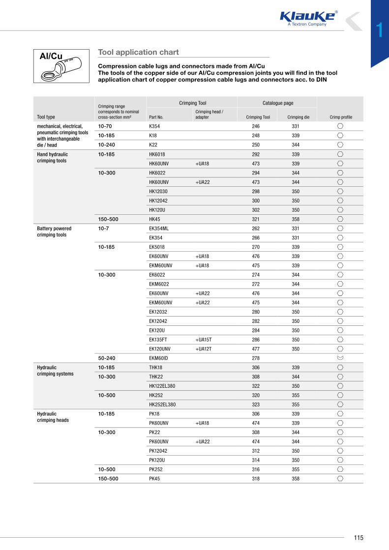
mechanical, electrical, pneumatic crimping tools with interchangeable die / head
10-70 K354 246 331
10-185 K18 248 339
10-240 K22 250 344
Hand hydraulic crimping tools
10-185 HK6018 292 339
HK60UNV +UA18 473 339
10-300 HK6022 294 344
HK60UNV +UA22 473 344
HK12030 298 350
HK12042 300 350
HK120U 302 350
150-500 HK45 321 358
Battery powered crimping tools
10-7 EK354ML 262 331
EK354 266 331
10-185 EK5018 270 339
EK60UNV +UA18 476 339
EKM60UNV +UA18 475 339
10-300 EK6022 274 344
EKM6022 272 344
EK60UNV +UA22 476 344
EKM60UNV +UA22 475 344
EK12032 280 350
EK12042 282 350
EK120U 284 350
EK135FT +UA15T 286 350
EK120UNV +UA12T 477 350
50-240 EKM60ID 278
Hydraulic crimping systems
10-185 THK18 306 339
10-300 THK22 308 344
HK122EL380 322 350
10-500 HK252 320 355
HK252EL380 323 355
Hydraulic crimping heads
10-185 PK18 306 339
PK60UNV +UA18 474 339
10-300 PK22 308 344
PK60UNV +UA22 474 344
PK12042 312 350
PK120U 314 350
10-500 PK252 316 355
150-500 PK45 318 358
Tool application chart
Compression cable lugs and connectors made from Al/CuThe tools of the copper side of our Al/Cu compression joints you will find in the toolapplication chart of copper compression cable lugs and connectors acc. to DIN
Tool type
Crimping range corresponds to nominal cross-section mm²
Crimping Tool Catalogue page
Crimp profilePart No.Crimping head / adapter Crimping Tool Crimping die
115
1

Clamps and screw connectorsElectrical connection systems
UNCOMPLICATED - CLAMPS AND SCREW CONNECTORSSimple connecting of dissimilar materials and cross-sections. Made
possible by Klauke clamps and screw connectors: They suit all standard
sizes and materials. In compliance with the specified safety measures,
compact tab connectors, for instance, can be installed even when live.
All very straightforward.
In brief
`` Simple branching without having to cut the main conductor with Klauke H and C clamps
`` H clamps to DIN EN 50164-1 short-circuit current tested
`` Also available in a barrier version for Al/Cu connections
116

` Screwing instead of crimping
Connect the conductors using screws. Why? Because no
special tools are needed. Screws are available for every
application. To make sure they last, all our screw connectors
are produced from high-quality materials. Simply an efficient
solution!
◾ Connections from 2.5 mm2 to 185 mm2 nominal cross-
section
◾ No special tool required
◾ The right screw solution to suit a host of requirements
◾ For aluminium and copper conductors
◾ For round and sector shaped conductors
◾ For conductors and wires
◾ High-quality aluminium alloy
` Clamps for continuous supply
We don’t abandon your supply. With Klauke clamps, your
operation can continue without outage, you carry out the
installation even while live. No standstill, the operation
continues.
◾ Especially suitable for the energy supply industry
◾ Can be installed while live
◾ Main conductor remains intact
◾ Different versions available for 3 and 4 core cables
` Continuously connected
Save yourself the trouble, the conductor does not need to be
cut. Various nominal cross-sections can be clamped with
multi-purpose clamps.
◾ Flexible due to the large cross-sectional range, C-clamps
from 2.5 mm2 to 185 mm2 nominal cross-sections,
H-clamps from 70 mm2 nominal cross-section
◾ Efficient connections, without having to cut the main
conductor.
◾ Straightforward connection of various cross-sections.
117
1

Electrical connection systemsClamps and screw connectors
Nominal cross section
mm² Part No.
Dimension mmNumber of
screws Torque NmWeight/pcs.
~kgPacking unit/pcsb b1 d2 k h l
6 - 10 572R6 15.0 18.0 6.5 M4 10 23.0 2 4 1.30 50
10 - 16573R6 15.0 20.5 6.5 M5 14 27.0 2 6 1.30 50
573R8 15.0 20.5 8.5 M5 14 27.0 2 6 1.30 50
16 - 25
574R8 15.0 25.0 8.5 M5 16 30.0 2 6 2.75 50
584R8 18.5 22.5 8.5 M5 16 36.0 4 6 3.70 25
584R10 19.5 22.5 10.5 M5 16 37.0 4 6 3.75 25
25 - 35
575R8 18.5 24.0 8.5 M5 16 25.5 2 6 2.50 50
585R8 18.5 24.0 8.5 M5 16 38.5 4 6 4.30 25
585R10 21.5 24.0 10.5 M5 16 42.0 4 6 4.65 25
585R12 21.5 24.0 13.0 M5 16 42.0 4 6 4.50 25
35 - 50586R10 19.0 28.0 10.5 M6 19 46.0 4 8 6.75 25
586R12 21.0 28.0 13.0 M6 19 47.0 4 8 6.70 25
50 - 70587R10 23.5 31.0 10.5 M6 19 51.0 4 8 9.35 10
587R12 23.5 31.0 13.0 M6 19 51.0 4 8 9.30 10
70 - 95588R10 24.0 34.0 10.5 M6 25 57.0 4 8 12.00 10
588R12 24.0 34.0 13.0 M6 25 57.0 4 8 11.85 10
95 - 150
589R10 30.0 42.0 10.5 M8 32 61.0 4 20 20.15 10
589R12 30.0 42.0 13.0 M8 32 61.0 4 20 20.20 10
589R16 30.0 42.0 17.0 M8 32 61.5 4 20 20.10 10
150 - 240
590R10 34.0 48.5 10.5 M8 32 68.5 4 20 24.40 5
590R12 34.0 48.5 13.0 M8 32 68.5 4 20 24.35 5
590R16 34.0 48.5 17.0 M8 32 68.5 4 20 24.30 5
590R20 36.0 48.5 21.0 M8 32 70.5 4 20 24.25 5
185 - 300
592R12 32.0 50.0 13.0 M8 37 68.5 4 20 27.95 5
592R16 32.0 50.0 17.0 M8 37 68.5 4 20 28.00 5
592R20 34.5 50.5 21.0 M8 37 70.0 4 20 27.95 5
Punched cable lugs, Cu
` For connecting of round conductors to DIN EN 60228 Cl. 1 and 2, for example in lightning protection areas
Characteristics▪ Also for outdoor assembly▪ Available with 2 or 4 screws
Material▪ Copper (ETP)▪ Screws: DIN 84 / DIN 933 bronze, F 60
Surface▪ Tin-plated to protect against corrosion
Additional information▪ Part Number appendix for bright version „BK“
118

Nominal cross section mm²
Part No.
Dimension mm
Weight/pcs. ~kg Packing unit/pcsd1 l Ø q z
6 551R 3.5 25 3.3 2 0.60 10
10 552R 4.5 30 3.3 2 1.20 10
16 553R 5.5 40 4.2 4 1.90 10
25 554R 7.0 45 4.2 4 2.85 10
35 555R 8.5 45 5.0 4 3.00 10
50 556R 10.0 48 5.0 4 4.00 10
70 557R 12.0 52 6.8 4 6.30 10
95 558R 13.5 55 6.8 4 8.05 10
120 559R 15.0 60 6.8 4 9.90 10
150 560R 17.0 64 6.8 4 11.80 5
185 561R 19.0 70 6.8 10 14.30 5
240 562R 21.0 70 6.8 10 15.50 5
300 563R 24.0 75 6.8 10 19.30 1
Tubular soldering sleeves, CuZn
` For round conductors, e.g. to DIN EN 60228 Cl. 1, 2, 5 and 6` Processed without using a crimping tool
Characteristics▪ Simple processing due to fixed screws and solder hole
Material▪ CuZn 40 Pb 2▪ Screws: Steel to DIN 551
Surface▪ Tin-plated to protect against corrosion
Technical instructions▪ z = number of grub screws▪ A connection needs to be soldered
119
1

Electrical connection systemsClamps and screw connectors
Nominal cross section mm²
Part No.
Dimension mm
M Torque Nm Weight/pcs. ~kg Packing unit/pcsb h l
Without thrust plate
2.5 - 16 SAK10 19.5 16 16 M5 6 2.10 10
2.5 - 25SAK12 25.0 21 18 M6 8 4.10 10
SAK14 25.0 22 20 M7 14 3.95 10
6 - 35 SAK16 28.0 23 20 M7 14 6.0 10
6 - 50SAK18 32.5 26 24 M7 14 8.0 10
SAK20 33.5 27 22 M8 20 8.6 10
6 - 70 SAK22 37.5 29 24 M8 20 11.1 5
10 - 95 SAK24 41.0 36 28 M8 20 15.6 5
With thrust plate
2.5 - 16 SAK11 19.5 16 16 M5 6 2.6 10
2.5 - 25SAK13 25.0 21 18 M6 8 4.30 10
SAK15 25.0 22 18 M7 14 4.6 10
6 - 35 SAK17 28.0 23 20 M7 14 6.3 10
6 - 50SAK19 32.5 26 20 M7 14 7.9 10
SAK21 33.5 27 22 M8 20 9.1 10
6 - 70 SAK23 37 29 24 M8 20 11.6 5
10 - 95 SAK25 45.0 36 31 M10 39 19.60 5
Parallel groove clamps, Cu, 1 screw
` For non-tension copper cables acc. to DIN 48201 part 1` For screwing conductors acc. to DIN EN 60228 Class 1 and 2,
for example in lightning protection areas
Characteristics▪ Also for outdoor assembly▪ Version with 1 screw▪ Optionally available with thrust plate for equal pressure distribution
Material▪ Copper (ETP)▪ Screws:Bronze F 60▪ Nut: copper
Surface▪ Bright
120

Nominal cross section mm²
Part No.
Dimension mm
A M Torque NmWeight/pcs.
~kgPacking unit/
pcsb h l
Without thrust plate
2.5 - 16 SAK30 20.5 16.0 24 13.0 M5 6 3.7 10
2.5 - 25SAK32 25.5 21 27 13.5 M6 8 6.4 10
SAK34 25.0 22 30 15.0 M7 14 7.7 10
6 - 35 SAK36 30.0 23 30 15 M7 14 8.5 10
6 - 50 SAK38 33.0 26 32 16.0 M7 14 12.3 10
10 - 50 SAK40 32.5 27 36 18.0 M8 20 12.9 10
10 - 95 SAK44 45.0 36 46 25.5 M10 39 28.7 5
16 - 150 SAK46 52.5 40 52 26.0 M10 39 37.4 5
With thrust plate
2.5 - 16 SAK31 19.5 16 24 13.0 M5 6 4.1 10
2.5 - 25SAK33 25.5 21 27 14.0 M6 8 7.0 10
SAK35 25.0 22 30 15.0 M7 14 7.9 10
6 - 35 SAK37 28.0 23 32 16.0 M7 14 10.2 10
6 - 50 SAK39 33.0 26 32 17.0 M7 14 12.8 10
10 - 50 SAK41 32.5 27 34.5 18.0 M8 20 14.7 10
6 - 70 SAK43 37.0 29 38.5 19.0 M8 20 19.1 5
10 - 95 SAK45 41.0 36 43 20.0 M8 20 25.0 5
16 - 150 SAK47 52.5 40 52 26.0 M10 39 39.0 5
Parallel groove clamps, Cu, 2 screws
` For non-tension copper cables acc. to DIN 48201 part 1` For screwing conductorsacc. to DIN EN 60228 Cl. 1 and 2,
for example in lightning protection areas
Characteristics▪ Also for outdoor assembly▪ Version with 2 screws▪ Optionally available with thrust plate for equal pressure distribution
Material▪ Copper (ETP)▪ Screws:Bronze F 60▪ Nut: copper
Surface▪ Bright
Technical instructions▪ When connecting cross sections 95, 120 and 150 mm² two power branch clamps
are to be used due to the current carrying capacity.
121
1

Electrical connection systemsClamps and screw connectors
Part No.
Cross section mm² rm/re Dimension mm
Weight/pcs. ~kg Packing unit/pcsHint Main conductor Tab conductor b l
CK16 16/25 16/25 16.0 15 0.94 25
CK25 * 25/35 25/35 20.0 16 1.68 25
CK35 35/50 35/50 25.7 22 3.42 25
CK50 50/- 50/- 28.0 23 4.88 25
CK70 70/- 70/- 34.0 28 9.69 10
CK95 95/- 95/- 35.0 28 7.30 10
Part No.
Cross section mm² rm/re Dimension mm
Weight/pcs. ~kg Packing unit/pcsMain conductor Tab conductor b l
MCK44 2.5 - 4/2.5 - 4 2.5 - 4/2.5 - 4 9.8 8 0.185 25
MCK1010 6 - 10/10 4 - 6/4 - 10 12.0 12 0.460 25
MCK1016 10 - 16/16 4 - 10/4 - 10 19.0 17 1.900 25
MCK1025 16 - 25/25 4 - 10/4 - 10 19.0 17 1.900 25
MCK3535 16 - 25/25 - 35 16 - 25/16 - 35 20.0 17 1.750 25
MCK2550 35/50 4 - 25/4 - 25 24.8 23 4.400 25
MCK5050 35/50 16 - 35/25 - 50 26.5 23 4.200 25
MCK3570 50 - 70/- 4 - 35/4 - 35 33.8 28 10.700 10
See next page
Branch clamps in C-type, Cu
` Ideal for clamping identical conductor cross-sections e.g. to VDE 60228 Cl. 1 and 2
` No need to cut the main conductor
Material▪ Copper (ETP)
Surface▪ Tin-plated to protect against corrosion
Technical instructions▪ Optimum conducting characteristics in combination with compound▪ Tool: see page 133
Additional information▪ Part Number appendix for bright version „BK“▪ rm = round multi-stranded; re = round single solid▪ * = Also suitable for 25 mm² round solid
Branch clamps in C-type, Cu, multi-purpose clamps
` Ideal for clamping non-identical conductor cross-sections e.g. to VDE 60228 Cl. 1 and 2
` No need to cut the main conductor
Material▪ Copper (ETP)
Surface▪ Tin-plated to protect against corrosion
Technical instructions▪ Optimum conducting characteristics in combination with compound▪ Tool: see page 133
Additional information▪ Part Number appendix for bright version „BK“▪ rm = round multi-stranded; re = round single solid
122

Part No.
Cross section mm² rm/re Dimension mm
Weight/pcs. ~kg Packing unit/pcsMain conductor Tab conductor b l
MCK3595 95/- 16 - 35 41.0 30 15.000 10
MCK7095 95/- 35 - 70 41.0 30 14.000 10
MCK120120 120/- 35 - 120 45.0 30 16.550 10
MCK150150 150/- 70 - 150 53.0 35 23.000 5
MCK185185 185/- 95 - 185 60.0 40 33.000 5
Part No.
Cross section mm² rm/re
Hint
Dimension mm
Weight/pcs. ~kg Packing unit/pcsMain conductor Tab conductor b l
AH7070 70 70 * 17.0 28.0 6.5 25
AH9595 95 95 22.0 30.0 10.0 25
AH120120 120 120 24.0 25.0 9.8 25
Part No.
KF125
Branch clamps in C-type, Cu, multi-purpose clamps
Branch clamps in H-type, Cu
` Ideal for clamping identical conductor cross-sections e.g. to DIN EN 60228` Lightning protection tested to EN 50164-1` No need to cut the main conductor
Characteristics▪ H-shape allows simple processing▪ Optimum conducting characteristics when used with compound
Material▪ Copper (ETP)
Surface▪ Tin-plated to protect against corrosion
Technical instructions▪ Tool: see page 134
Additional information▪ Part Number appendix for bright version „BK“▪ * = To EN 50164-1 lightning current tested
Compound for branch clamps
` Optimum conductivity properties for processing aluminium cable lugs and connectors and branch clamps (C and H-type)
Characteristics▪ Water-resistant, with corundum for destroying the oxidation layer▪ Content/tin: 0.125 kg
123
1

Electrical connection systemsClamps and screw connectors
Part No.
Nominal cross section mm² Dimension mm
Torque NmWeight/pcs.
~kgPacking unit/
pcsre rm D d1 L AF
SV100 6 - 35 6 - 25 14 7.2 40 4 10 3.9 4
Part No.
Nominal cross section mm² Dimension mm
Torque NmWeight/pcs.
~kgPacking unit/
pcsre rm D d1 L AF
With threaded pin, tin-plated
SV200 1.5 - 16 1.5 - 16 10 5.5 30 2.5 4 1.35 4
With threaded pin, bright finished
SV200BK 1.5 - 16 1.5 - 16 10 5.5 30 2.5 4 1.35 4
Screw connectors for shielded copper wires
` Suitable cross-section range, for example shielded copper wires` Ideal for connecting various conductor types and materials, e.g. to DIN EN
60228 Cl. 1 and 2
Characteristics▪ Special groove profile inside to destroy the oxidation layer when crimping▪ With inspection hole for monitoring full cable insertion
Material▪ Insulated body: brass (CuZn)▪ Screws: stainless steel, tin-plated
Surface▪ Tin-plated to protect against corrosion
Technical instructions▪ Refer to the installation instructions in the technical appendix on page i-9
Additional information▪ rm = round multi-stranded; re = round single solid
Screw connectors for street lighting
` Ideal for connecting various conductor types and materials, e.g. to DIN EN 60228 Cl. 1 and 2
` Suitable cross-section range for street lighting
Characteristics▪ Special groove profile inside to destroy the oxidation layer when crimping▪ With inspection hole for monitoring full cable insertion
Material▪ Insulated body: brass (CuZn)▪ Screws: stainless steel, tin-plated
Surface▪ Either bright or tin-plated
Technical instructions▪ Refer to the installation instructions in the technical appendix on page i-9
Additional information▪ rm = round multi-stranded; re = round single solid
` For connecting different conductor types and materials, e.g. to DIN EN 60228 Class 1 and 2
` Ideal for connecting identical and different conductor cross-sections
124

Part No.
Nominal cross section mm²
Hint
Dimension mmTorque
NmWeight/pcs. ~kg
Packing unit/pcsre rm se sm D L AF
With threaded pin, bright finishedSV303 6 - 35 6 - 25,
Cu 2.5 - 50 (v)-- Cu 2.5 - 35 14 40 4 8 1.5 4
SV300 -- Al 6 - 50 (v) -- Al 6 - 35, 35 - 70
16.5 40 4 9 1.7 4
SV301 16 - 95 16 - 95 50 - 95, 50 - 120 (120°)
35 - 95 (r) 25 55 5 20 6.6 4
SV308 25 - 150 25 - 150 50 - 150 (90°), 50 - 150 (120°)
-- 28 70 6 25 11.3 4
SV302 35 - 50 95 - 185 50 - 185 (90°) 35 - 150 32 80 6 25 16 4
Without threaded pin, bright finished
SV303V 6 - 35 6 - 25, Cu 2.5 - 50 (v)
-- Cu 2.5 - 35 14 40 4 8 1.5 4
SV300V -- Al 6 - 50 (v) -- Al 6 - 35 16.5 40 4 9 1.7 4
SV307V 50 - 70 10 - 70 50 - 70 35 - 70, 35 - 70 22 57 5 15 4.7 4
SV301V 16 - 95 16 - 95 50 - 95, 50 - 150 (120°)
35 - 95 (r) 25 55 5 20 6.6 4
SV302V 35 - 50 35*185 50 - 185 (90°) 35 - 150 32 80 6 25 16 4
With shear head, bright finished
SV303AK 6 - 35 6 - 25 -- -- * 14 40 4 8 1.5 1
SV303AKNL 6 - 35 6 - 25, Cu 2.5 - 50 (v)
-- Cu 2.5 - 35 * 14 40 4 8 1.5 1
SV304AKNL -- Al 6 - 50 (v) -- Al 6 - 35 16.5 40 4 9 1.7 4
SV307AKNL 10 - 70 10 - 70 50 - 70 35 - 70, 35 - 70 22 57 5 15 4.7 4
SV301AK 16 - 95 16 - 95 50 - 95, 50 - 150 (120°)
35 - 95 (r), 35 - 150
25 55 5 20 6.6 4
SV302AK 35 - 50 35 - 185 50 - 185 (90°) 35 - 185 (r) 32 80 6 25 16 4
With shear head, tin - plated
SV304AKNLV -- Cu 2.5 - 50 (v), Al 6 - 50 (v)
-- Cu 2.5 - 35, Al 6 - 35
16.5 40 4 9 1.7 4
SV301AKV 16 - 95 16 - 95 50 - 95 35 - 70, 35 - 95 (r)
** 25 55 5 20 6.6 4
SV302AKV 35 - 50 35 - 185 50 - 150 (120°), 50 - 185 (90°)
35 - 150 32 80 6 25 16 4
Screw connector with 2 screws
` For connecting various conductor types and materials, e.g. to DIN EN 60228 Cl. 1 and 2
` Ideal for connecting identical and different conductor cross-sections` Reliable processing due to cable insertion control
(dissimilar materials must not come into contact)
Characteristics▪ Special groove profile inside to destroy the oxidation layer when crimping▪ Either with threaded pin or shear head, shear head partly fixed▪ Version with 2 screws
Material▪ Insulated body: high-tensile aluminium alloy▪ Screws: copper alloy, tin-plated
Surface▪ Either bright or tin-plated
Technical instructions▪ Refer to the installation instructions in the technical appendix on pagei-9
Additional information▪ * = fixed version, Part Number appendix „NL“▪ **= version with fixed countersink shear head, Part Number appendix „VK“▪ re = round single solid wire, rm = round multi-stranded, se = sector shaped single
solid wire, sm = sector shaped multi-stranded, (r) = pre-rounded, (v) = compacted
125
1

Electrical connection systemsClamps and screw connectors
Part No.
Nominal cross section mm²
Hint
Dimension mmTorque
NmWeight/pcs. ~kg
Packing unit/pcsre rm se sm D l L AF
With threaded pin, bright finished
SV315 -- Cu 2.5 - 50 (v), Al 6 - 50 (v)
-- Cu 2.5 - 35, Al 6 - 35
16 17.5 40 4 9 1.7 4
SV309 16 - 95 16 - 95 50 - 95, 50 - 120 (120°)
35 - 70 (r) 25 22 55 5 20 6.6 4
SV320 25 - 150 25 - 150 50 - 150 (90°), 50 - 150 (120°)
35 - 150 28 31 70 6 25 11.3 4
SV310 35 - 50 35 - 185 50 - 185 (90°) 35 - 185 (r) 32 32 80 6 25 16 4
With threaded pin, tin-plated
SV315V -- Cu 2.5 - 50 (v), Al 6 - 50 (v)
-- Cu 2.5 - 35, Al 6 - 35
16 17.5 40 4 9 1.7 4
SV309V 16 - 95 16 - 95 50 - 95, 50 - 120 (120°)
35 - 95 (r) 25 22 55 5 20 6.6 4
SV320V 25 - 150 25 - 150 50 - 150 (90°), 50 - 150 (120°)
-- 28 31 70 6 25 11.3 4
SV310V 35 - 50 35 - 185 50 - 185 (90°) 35 - 185 (r) 32 32.5 80 6 25 16 4
With shear head, bright finished
SV311AKNL 6 - 35 6 - 25, Cu 2.5 - 50 (v)
-- Cu 2.5 - 35 14 17.5 40 4 8 1.5 4
SV312AKNL -- Al 6 - 50 (v) -- Al 6 - 35, 35 - 70
16 17.5 40 4 9 1.7 4
SV309AK 16 - 95 16 - 95 50 - 95, 50 - 150 (120°)
35 - 95 (r), 35 - 150
25 22 55 5 20 6.6 4
SV310AK 35 - 50 35 - 185 50 - 185 (90°) 35 - 185 (r) 32 32.5 80 6 25 16 4
With shear head, tin-plated
SV312AKNLV -- Cu 2.5 - 50 (v), Al 6 - 50 (v)
-- Cu 2.5 - 35, Al 6 - 35
16 17.5 40 4 9 1.7 4
SV319AKNLV 10 - 70 10 - 70 50 - 70 35 - 70 22 24 57 5 15 7.6 4
SV309AKV 16 - 95 16 - 95 50 - 95, 50 - 150 (120°)
35 - 95 (r), 35 - 150
* 25 22 55 5 20 6.6 4
SV310AKV 35 - 50 35 - 185 50 - 185 (90°) 35 - 185 (r) * 32 32.5 80 6 25 16 4
Screw connector with barrier
` For connecting various conductor types and materials, e.g. to DIN EN 60228 Cl. 1 and 2
` Ideal for connecting identical and different conductor cross-sections
Characteristics▪ Special groove profile inside to destroy the oxidation layer when crimping▪ Either with threaded pin or shear head, shear head partly fixed▪ Version with 2 screws and barrier
Material▪ Insulated body: high-tensile aluminium alloy▪ Screws: copper alloy, tin-plated
Surface▪ Either bright or tin-plated
Technical instructions▪ Refer to the installation instructions in the technical appendix on page i-9
Additional information▪ re = round single solid wire, rm = round multi-stranded, se = sector shaped single
solid wire, sm = sector shaped multi-stranded, (r) = pre-rounded, (v) = compacted
126

Part No.
Nominal cross section mm² Dimension mm
Torque NmWeight/pcs.
~kgPacking unit/pcsre rm se sm D L AF
With threaded pin, bright finished
SV305 16 - 95 16 - 95 50 - 9535 - 70,
35 - 70 (r)25 92 5 20 12 4
SV306 35 - 50 35 - 18550 - 150 (120°),
50 - 185 (90°)35 - 185 (r) 32 108 6 25 25 4
With threaded pin, tin-plated
SV305V 16 - 95 16 - 95 50 - 9535 - 70,
35 - 70 (r)25 92 5 20 12 4
SV306V 35 - 50 35 - 18550 - 150 (120°),
50 - 185 (90°)
35 - 150, 35 - 185 (r)
32 108 6 25 25 4
With shear head, bright finished
SV305AK 16 - 95 16 - 95 50 - 9535 - 70,
35 - 70 (r)25 92 5 20 12 4
SV306AK 35 - 50 35 - 18550 - 150 (120°),
50 - 185 (90°)
35 - 150, 35 - 185 (r)
32 108 6 25 25 4
With shear head, tin-plated
SV305AKV 16 - 95 16 - 95 50 - 9535 - 70,
35 - 70 (r)25 92 5 20 12 4
SV306AKV 35 - 50 35 - 18550 - 150 (120°),
50 - 185 (90°)
35 - 150, 35 - 185 (r)
32 108 6 25 25 4
Screw connector with 4 screws
` For connecting various conductor types and materials, e.g. to DIN EN 60228 Cl. 1 and 2
` Ideal for connecting identical and different conductor cross-sections` Reliable processing due to cable insertion control (dissimilar materials must
not come into contact)
Characteristics▪ Special groove profile inside to destroy the oxidation layer when crimping▪ Available with threaded pin or shear head▪ Version with 4 screws
Material▪ Insulated body: high-tensile aluminium alloy▪ Screws: copper alloy, tin-plated
Surface▪ Either bright or tin-plated
Technical instructions▪ Refer to the installation instructions in the technical appendix on page i-9
Additional information▪ re = round single solid wire, rm = round multi-stranded, se = sector shaped single
solid wire, sm = sector shaped multi-stranded
127
1

Electrical connection systemsClamps and screw connectors
Part No.
Nominal cross section mm² Dimension mm
Torque NmWeight/pcs.
~kgPacking unit/pcsre rm se sm D L AF
With threaded pin, bright finished
SV400 6 - 35 6 - 25 50 - 70 (120°) 35 - 70 14 60 4 8 1.7 4
SV410 16 - 50 16 - 9550 - 95 (90°),
50 - 150 (120°)
35 - 95 (r), 35 - 150
28.2 58.2 5 20 6 4
SV420 35 - 50 35 - 185 50 - 185 (90°) 35 - 185 (r) 36 84 6 25 14.5 4
With threaded pin, tin-plated
SV405V 10 - 70 10 - 7050 - 70, 50 - 150 (120°)
35 - 70, 35 - 150
25 87 5 15 5 4
SV420V 35 - 50 35 - 185 50 - 185 (90°) 35 - 185 (r) 36 84 6 25 14.5 4
With shear head, bright finished
SV410AK 16 - 50 16 - 9550 - 70 (120°), 50 - 95 (90°)
35 - 70, 35 - 95 (r)
28.2 58.2 5 20 6 4
SV420AK 35 - 50 35 - 18550 - 150 (120°),
50 - 185 (90°)
35 - 150, 35 - 185 (r)
36 84 6 25 14.5 4
Insulated screw connector
` For connecting various conductor types and materials, e.g. to DIN EN 60228 Cl. 1 and 2
` Ideal for connecting identical and different conductor cross-sections` Reliable processing due to cable insertion control
(dissimilar materials must not come into contact)
Characteristics▪ Special groove profile inside to destroy the oxidation layer when crimping▪ Insulated body▪ Version with 2 screws, without barrier▪ Available with threaded pin or shear head
Material▪ Insulated body: high-tensile aluminium alloy▪ Screws: copper alloy, tin-plated
Surface▪ Either bright or tin-plated
Technical instructions▪ Refer to the installation instructions in the technical appendix on page i-9
Additional information▪ re = round single solid wire, rm = round multi-stranded, se = sector shaped single
solid wire, sm = sector shaped multi-stranded
128

Part No.
Nominal cross section mm²
Hint
Dimension mmTorque
NmWeight/pcs. ~kg
Packing unit/pcsre rm se sm D l L AF
With threaded pin, bright
SV430 16-50 16-9550 - 70 (120°), 50 - 95 (90°)
35 - 70, 35 - 95 (r)
28.2 23.6 58.2 5 20 6.6 4
SV440 35-50 35-18550 - 150 (120°),
50 - 185 (90°)
35 - 150, 35 - 185 (r)
36 34.5 84 6 25 16.0 4
With shear head
SV430AK 16 - 50 16 - 9550 - 70 (120°), 50 - 95 (90°)
35 - 70, 35 - 95 (r)
28.2 23.6 58.2 5 20 6.6 4
SV440AK 35 - 50 35 - 18550 - 150 (120°),
50 - 185 (90°)
35 - 150, 35 - 185 (r)
** 36 34.5 84 6 25 16.0 4
Screw connector with barrier
` For connecting various conductor types and materials, e.g. to DIN EN 60228 Cl. 1 and 2
` Ideal for connecting identical and different conductor cross-sections
Characteristics▪ Special groove profile inside to destroy the oxidation layer when crimping▪ Either with threaded pin or shear head, shear head partly fixed▪ Version with 2 screws and barrier
Material▪ Insulated body: high-tensile aluminium alloy▪ Screws: copper alloy, tin-plated
Surface▪ Either bright or tin-plated
Technical instructions▪ Refer to the installation instructions in the technical appendix on page i-9
Additional information▪ re = round single solid wire, rm = round multi-stranded, se = sector shaped single
solid wire, sm = sector shaped multi-stranded, (r) = pre-rounded, (v) = compacted
129
1

Electrical connection systemsClamps and screw connectors
Part No.
Main conductor Tap conductor Dimension mm
Torque NmWeight/pcs.
~kgPacking unit/pcsse sm se sm la lb Width AF
KSK1503 70 - 150 150 95 (r) 6 - 70 (r) 84 76 45 5 20 0.35 1
Part No.
Main conductor Tap conductor Dimension mmTorque
NmWeight/pcs.
~kgPacking unit/pcsse sm se sm la lb Width AF
KSK1504 70 - 150 150 95 (r) 6 - 70 (r) 107 90 46 5 20 0.63 1
KSK1854 70 - 150 150 95 (r) 6 - 70 (r) 107 90 46 5 20 0.58 1
Compact tap connectors with shear heads, three conductor cables
` Suitable for main and branch conductors made from Al and Cu` No need to cut the main conductor` For use e.g. with energy suppliers
Characteristics▪ VDE: can be installed under voltage with corresponding fully insulated assembly tools▪ With shear heads for the main conductor, fixed
Technical instructions▪ A mounting instruction is included with every clamp
Additional information▪ re = round single solid wire, rm = round multi-stranded, se = sector shaped single
solid wire, sm = sector shaped multi-stranded▪ Creepage and elongation processes are compensated for by spring washers▪ Sequence of contacting can be freely determined
Compact tap connectors with shear heads, four conductor cables
` Suitable for main and branch conductors made from Al and Cu` No need to cut the main conductor` For use e.g. with energy suppliers
Characteristics▪ VDE: can be installed under voltage with corresponding fully insulated assembly tools▪ With shear heads for the main conductor, fixed
Technical instructions▪ A mounting instruction is included with every clamp
Additional information▪ re = round single solid wire, rm = round multi-stranded, se = sector shaped single
solid wire, sm = sector shaped multi-stranded▪ Creepage and elongation processes are compensated for by spring washers▪ Sequence of contacting can be freely determined
130

Part No.
Main conductor Tap conductor Dimension mm
Torque NmWeight/pcs. ~kg
Packing unit/pcs se sm rm se sm la lb Width AF
KSK504Cu 25 - 50, Al 35 - 50
Cu 25 - 50 Cu 25 - 50 50 6-35 88 75 50 5 15 0.46 1
Part No.
Main conductor Tap conductor Dimension mmTorque
NmWeight/pcs. ~kg
Packing unit/pcsse sm re se sm rm la lb Width AF
SKR1204 120 70 - 95 50 (r) 6 - 35 (r) 90 77 50 5 20 0.46 1
SKR150504 150 70 - 150 50 50 6 - 35 93 80 50 5 20 0.46 1
SKR1504 70 - 150 150 95 (r) 6 - 70 (r) 107 90 46 5 20 0.62 1
SKR1501504 95 - 150 150 150 16 - 120 16 - 120 118 118 93 5 20 1.34 1
SKR1854 185 95 - 150 95 (r) 6 - 70 107 96 46 5 20 0.58 1
Compact tap connectors, four conductor cables, for main conductor 25 - 50 mm²
` Suitable for main and branch conductors made from Al and Cu` No need to cut the main conductor` For use e.g. with energy suppliers
Characteristics▪ VDE: can be installed under voltage with corresponding fully insulated assembly tools
Technical instructions▪ A mounting instruction is included with every clamp
Additional information▪ re = round single solid wire, rm = round multi-stranded, se = sector shaped single
solid wire, sm = sector shaped multi-stranded▪ Creepage and elongation processes are compensated for by spring washers▪ Sequence of contacting can be freely determined
Compact tap connectors, four conductor cables, for main conductor 70 - 185 mm²
` Suitable for main and branch conductors made from Al and Cu` No need to cut the main conductor` For use e.g. with energy suppliers
Characteristics▪ VDE: can be installed under voltage with corresponding fully insulated assembly tools▪ With threaded pins for the main conductor
Technical instructions▪ A mounting instruction is included with every clamp
Additional information▪ re = round single solid wire, rm = round multi-stranded, se = sector shaped single
solid wire, sm = sector shaped multi-stranded▪ Creepage and elongation processes are compensated for by spring washers▪ Sequence of contacting can be freely determined
131
1

Electrical connection systemsClamps and screw connectors
Part No.
Main conductor Tap conductor Dimension mmThread DIN 13
Weight/pcs. ~kg
Packing unit/pcsse sm rm re se sm la lb Width
Bolts Circle dia. AF
SKR1503 70 - 150 70 - 150 70 - 150 70 - 150 6 - 70 6 - 95 84 76 45 90 5M10x1/
M100.38 1
Compact tap connectors, three conductor cables
` Suitable for main and branch conductors made from Al and Cu` No need to cut the main conductor` For use e.g. with energy suppliers
Characteristics▪ VDE: can be installed under voltage with corresponding fully insulated assembly tools▪ With threaded pins for the main conductor
Technical instructions▪ A mounting instruction is included with every clamp
Additional information▪ re = round single solid wire, rm = round multi-stranded, se = sector shaped single
solid wire, sm = sector shaped multi-stranded
132

Tool application chart
C-Clamps
Mechanical, electrical, pneumatic crimping tools with interchangeable die / head
4-35 K354 246 331 331
4-50 K18 248 339 339
K22 250 345 345
Hand hydraulic crimping tools
4-50 HK6018 292 339 339
HK60UNV +UA18 473 339 339
HK6022 294 345 345
HK60UNV +UA22 473 345 345
10-70 HK12030 298 351 351
HK12042 300 351 351
HK120U 302 351 351
Battery powered crimping tools
4-35 EK354ML 262 331 331
EK354 266 331 331
4-50 EK5018 270 339 339
EK60UNV +UA18 476 339 339
EKM60UNV +UA18 475 339 339
EK6022 274 345 345
EKM6022 272 345 345
EK60UNV +UA22 476 345 345
EKM60UNV +UA22 475 345 345
10-70 EK12032 280 351 351
EK12042 282 351 351
EK120U 284 351 351
EK135FT +UA15T 286 351 351
EK120UNV +UA12T 477 351 351
Hydraulic crimping systems
4-50 THK18 306 339 339
THK22 308 345 345
10-70 HK122EL380 322 351 351
10-185 HK252 320 356 356
HK252EL380 323 356 356
Hydraulic crimping heads
4-50 PK18 306 339 339
PK60UNV +UA18 474 339 339
PK22 308 345 345
PK60UNV +UA22 474 345 345
10-70 PK12042 312 351 351
PK120U 314 351 351
10-185 PK252 316 356 356
Tool type
Crimping range corresponds to nominal cross-section mm²
Crimping Tool Catalogue page
Crimp profilePart No.Crimping head / adapter Crimping Tool Crimping die
133
1

Electrical connection systemsClamps and screw connectors
Tool application chart
H-Clamps
Mechanical, electrical, pneumatic crimping tools with interchangeable die / head
70 K22 250 345
Hand hydraulic crimping tools
70 HK6022 294 345
70-120 HK12030 298 351
HK12042 300 351
HK120U 302 351
Battery powered crimping tools
70 EK6022 274 345
EKM6022 272 345
EK60UNV +UA22 476 345
70-120 EK12032 280 351
EK12042 282 351
EK120U 284 351
EK135FT +UA15T 286 351
EK120UNV +UA12T 477 351
Hydraulic crimping systems
70 THK22 308 345
70-120 HK122EL380 322 351
HK252 320 356
HK252EL380 323 356
Hydraulic crimping heads
70 PK22 308 345
70-120 PK12042 312 351
PK120U 314 351
PK252 316 356
Tool type
Crimping range corresponds to nominal cross-section mm²
Crimping Tool Catalogue page
Crimp profilePart No.Crimping head / adapter Crimping Tool Crimping die
134

135
1

In Kürze
`` Schutz vor aufspleißenden Leitern
`` bessere Kontaktierung
`` keine Kurzschlussgefahr durch abgebogene Adern
`` gefertigt aus hochwertigem Kupfer
`` Oberflächenbehandlung mit Zinn oder in Sonderformen mit Silber
Cable end-sleevesElectrical connection systems
PROTECTION - CABLE END-SLEEVES, INSULATED AND NON-INSULATEDKlauke joins together what belongs together. Cable end-sleeves prevent the conductors
splicing before they are connected in clamps. All wires remain together. Easy-Entry
insulation speeds up the insertion of wires into the sleeve. Fine-stranded conductors
in particular benefit from a special trapezoidal crimp. No splicing, no time wasted.
Your conductors are protected and can be cleanly processed
In brief
`` Stops conductors splicing
`` Improved contact
`` No risk of short-circuit due to bent strands
`` Produced from high-quality copper
`` Surface treatment with tin or in special versions with silver
136

` Always the right crimp shape
We give every cable end-sleeve its perfect crimp shape.
No matter where the conductor is to be laid later, we have
a solution for you.
◾ The correct crimp shape for every connecting terminal
◾ Crimp shapes matched to the DIN dimensions
◾ For compacted conductors
◾ Connect without risk of short-circuit
` Easy-Entry insulation
The special Easy-Entry insulation makes it easier to insert
the conductor into the sleeves. In addition, the insulation is
highly-resistant, to temperatures of up to 105 °C for example.
◾ Easy-Entry insulation for convenient insertion of the
conductor
◾ Temperature-resistant to 105 °C
◾ No toxic vapours in case of fire
◾ Ageing-resistant plastic collars
` Simple diversity
We have to admit: Cable end-sleeves are a simple product.
Due to the differing crimp shapes in the range and the
high-quality materials used in production, the sleeves are
just incredibly good.
◾ Broad range: To DIN standards, for short circuit-resistant
conductors, in various lengths, with and without insulating
collars
◾ Marked to DIN colour code
◾ Twin cable end-sleeves for connecting in confined areas
◾ High-quality material for optimum conducting properties
◾ CSA-approved
The easy-entry insulation enables fast
insertion of conductors with no splicing.
137
1

Electrical connection systemsCable end-sleeves
Nominal cross section mm² Part No. Hint
Dimension mm Weight/ 1000 pcs.
~ kg Packing unit/pcsd1 d2 l s
0.25695V * 0.75 1.7 5 0.15 0.02 1000
697V * 0.75 1.7 7 0.15 0.03 1000
0.34705V * 0.85 1.8 5 0.15 0.02 1000
707V * 0.85 1.8 7 0.15 0.03 1000
0.5
71S6V 1.00 2.1 6 0.15 0.03 1000
71S8V * 1.00 2.1 8 0.15 0.04 1000
71S10V 1.00 2.1 10 0.15 0.05 1000
0.75
716V 1.20 2.3 6 0.15 0.04 1000
718V * 1.20 2.3 8 0.15 0.05 1000
7110V 1.20 2.3 10 0.15 0.06 1000
7112V * 1.20 2.3 12 0.15 0.08 1000
7115V * 1.20 2.3 15 0.15 0.09 1000
1
72S6V 1.40 2.5 6 0.15 0.04 1000
72S8V * 1.40 2.5 8 0.15 0.06 1000
72S10V 1.40 2.5 10 0.15 0.07 1000
72S12V * 1.40 2.5 12 0.15 0.08 1000
72S15V * 1.40 2.5 15 0.15 0.10 1000
1.5
726V * 1.70 2.8 6 0.15 0.05 1000
727V 1.70 2.8 7 0.15 0.06 1000
728V * 1.70 2.8 8 0.15 0.07 1000
7210V 1.70 2.8 10 0.15 0.09 1000
7212V 1.70 2.8 12 0.15 0.10 1000
7215V * 1.70 2.8 15 0.15 0.13 1000
7218V 1.70 2.8 18 0.15 0.15 1000
7220V * 1.70 2.8 20 0.15 0.17 1000
2.5
737V 2.20 3.4 7 0.15 0.08 1000
738V * 2.20 3.4 8 0.15 0.09 1000
7310V 2.20 3.4 10 0.15 0.11 1000
7312V 2.20 3.4 12 0.15 0.13 1000
7315V * 2.20 3.4 15 0.15 0.17 1000
7318V 2.20 3.4 18 0.15 0.20 1000
7320V * 2.20 3.4 20 0.15 0.22 1000
See next page
Cable end-sleeves to DIN, Cu
` For fine and superfine stranded conductors, e.g. to DIN EN 60228 Cl. 5 and 6` Optimal cable entry due to widened sleeve
Characteristics▪ To DIN 46228, part 1 and similar
Material▪ Copper (EN13600)
Surface▪ Tin-plated to protect against corrosion
Technical instructions▪ Tool: see page 150
Additional information▪ Silvered version also available, without Part Number appendix “V“,
exception: Part Number 705V in silvered version = Part No. 7050▪ * = not standardised
138

Cable end-sleeves nach DIN, Cu
Nominal cross section mm² Part No. Hint
Dimension mm Weight/ 1000 pcs.
~ kg Packing unit/pcsd1 d2 l s
4
748V * 2.80 4.0 8 0.20 0.14 1000
749V 2.80 4.0 9 0.20 0.16 1000
7410V * 2.80 4.0 10 0.20 0.17 1000
7412V 2.80 4.0 12 0.20 0.20 1000
7415V 2.80 4.0 15 0.20 0.27 1000
7418V 2.80 4.0 18 0.20 0.32 1000
7420V * 2.80 4.0 20 0.20 0.35 1000
6
7510V 3.50 4.7 10 0.20 0.23 100
7512V 3.50 4.7 12 0.20 0.27 100
7515V 3.50 4.7 15 0.20 0.34 100
7518V 3.50 4.7 18 0.20 0.40 100
7520V * 3.50 4.7 20 0.20 0.45 100
7525V * 3.50 4.7 25 0.20 0.56 100
10
7610V * 4.5 5.8 10 0.2 0.27 100
7612V 4.5 5.8 12 0.2 0.33 100
7615V 4.5 5.8 15 0.2 0.41 100
7618V 4.5 5.8 18 0.2 0.49 100
7620V * 4.5 5.8 20 0.2 0.55 100
7625V * 4.5 5.8 25 0.2 0.68 100
16
7712V 5.8 7.5 12 0.2 0.43 100
7715V 5.8 7.5 15 0.2 0.53 100
7718V 5.8 7.5 18 0.2 0.60 100
7720V * 5.8 7.5 20 0.2 0.70 100
7725V 5.8 7.5 25 0.2 0.87 100
7732V 5.8 7.5 32 0.2 1.11 100
25
7812V * 7.3 9.5 12 0.2 0.80 50
7815V 7.3 9.5 15 0.2 0.99 50
7818V 7.3 9.5 18 0.2 1.18 50
7820V * 7.3 9.5 20 0.2 1.31 50
7825V 7.3 9.5 25 0.2 1.63 50
7828V * 7.3 9.5 28 0.2 1.82 50
7832V 7.3 9.5 32 0.2 2.07 50
35
7912V * 8.3 11.0 12 0.2 0.90 50
7915V * 8.3 11.0 15 0.2 1.12 50
7918V 8.3 11.0 18 0.2 1.34 50
7920V * 8.3 11.0 20 0.2 1.48 50
7922V * 8.3 11.0 22 0.2 1.63 50
7925V 8.3 11.0 25 0.2 1.80 50
7930V * 8.3 11.0 30 0.2 2.20 50
7932V 8.3 11.0 32 0.2 2.35 50
50
8018V 10.5 13.0 18 0.3 1.69 50
8022V * 10.5 13.0 22 0.3 2.05 50
8025V 10.5 13.0 25 0.3 2.32 50
8030V * 10.5 13.0 30 0.3 2.77 50
8032V 10.5 13.0 32 0.3 2.95 50
See next page
139
1

Electrical connection systemsCable end-sleeves
Cable end-sleeves nach DIN, Cu
Nominal cross section mm² Part No. Hint
Dimension mm Weight/ 1000 pcs.
~ kg Packing unit/pcsd1 d2 l s
70
8122V * 12.7 15.0 22 0.4 3.31 25
8125V * 12.7 15.0 25 0.4 3.75 25
8130V * 12.7 15.0 30 0.4 4.48 25
8132V * 12.7 15.0 32 0.4 4.78 25
95
8225V * 14.7 17.0 25 0.4 4.32 25
8230V * 14.7 17.0 30 0.4 5.17 25
8232V * 14.7 17.0 32 0.4 5.17 25
8234V * 14.7 17.0 34 0.4 5.84 25
120
8330V * 16.7 19.0 30 0.5 7.35 25
8332V * 16.7 19.0 32 0.5 7.83 25
8334V * 16.7 19.0 34 0.5 8.31 25
8338V * 16.7 19.0 38 0.5 9.28 25
8340V * 16.7 19.0 40 0.5 9.76 25
150
8432V * 18.7 21.0 32 0.5 8.75 25
8434V * 18.7 21.0 34 0.5 9.28 25
8438V * 18.7 21.0 38 0.5 10.36 25
8440V * 18.7 21.0 40 0.5 10.89 25
1858532V * 20.2 23.5 32 0.6 11.38 25
8540V * 20.2 23.5 40 0.6 14.17 25
2408634V * 23.0 24.0 34 0.5 11.25 25
8640V * 23.0 24.0 40 0.5 13.23 25
Nominal cross section mm²
Nominal size to DIN Part No.
Dimension mm Weight/ 1000 pcs.
~ kgPacking unit/
pcs a1 l1 l2 l3 s
0.5-1 B 1 - 7 SH271 2.5 11 3.5 7 0.3 0.20 100
1.5 B 1.5 - 7 SH272 2.5 11 3.5 7 0.3 0.23 100
2.5 B 2.5 - 7 SH273 2.5 11 3.5 7 0.3 0.32 100
Cable end-sleeves to DIN, CuZn
` For fine and superfine stranded conductors, e.g. to DIN EN 60228 Cl. 5 and 6
Characteristics▪ To DIN 46228, part 2
Material▪ Brass (CuZn)
Surface▪ Tin-plated to protect against corrosion
Technical instructions▪ Tool: see page 152
140

Nominal cross section mm² Part No. Colour Hint
Dimension mm Weight/ 1000 pcs.
~ kgPacking unit/
pcs d1 d3 l1 l2 s1
0.5
4696 1.0 3.1 12 6 0.15 0.070 1000
4698 1.0 3.1 14 8 0.15 0.070 1000
GR4698 *** 1.0 3.1 14 8 0.15 0.070 500
46910 1.0 3.1 16 10 0.15 0.085 1000
0.75
4706 1.2 3.3 12 6 0.15 0.080 1000
4708 1.2 3.3 14 8 0.15 0.080 1000
GR4708 *** 1.2 3.3 14 8 0.15 0.080 500
47010 1.2 3.3 16 10 0.15 0.100 1000
47012 1.2 3.3 18 12 0.15 0.105 1000
1
4716 1.4 3.5 12 6 0.15 0.090 1000
4718 1.4 3.5 14 8 0.15 0.100 1000
GR4718 *** 1.4 3.5 14 8 0.15 0.100 500
47110 1.4 3.5 16 10 0.15 0.120 1000
47112 1.4 3.5 18 12 0.15 0.125 1000
1.5
4726 1.7 4.0 12 6 0.15 0.105 1000
4728 1.7 4.0 14 8 0.15 0.110 1000
GR4728 *** 1.7 4.0 14 8 0.15 0.110 500
47210 1.7 4.0 16 10 0.15 0.130 1000
47212 1.7 4.0 18 12 0.15 0.150 1000
47218 1.7 4.0 24 18 0.15 0.190 1000
2.5
4738 2.2 4.7 14 8 0.15 0.150 1000
GR4738 *** 2.2 4.7 14 8 0.15 0.150 500
47312 2.2 4.7 18 12 0.15 0.200 1000
47318 2.2 4.7 24 18 0.15 0.250 1000
4
47410 2.8 5.4 17 10 0.20 0.210 100
47412 2.8 5.4 20 12 0.20 0.250 100
47418 2.8 5.4 26 18 0.20 0.320 100
647512 3.5 6.9 20 12 0.20 0.350 100
47518 3.5 6.9 26 18 0.20 0.460 100
1047612 4.5 8.4 22 12 0.20 0.450 100
47618 4.5 8.4 28 18 0.20 0.650 100
See next page
Insulated cable end-sleeves to DIN, with Easy-Entry
` For fine and superfine stranded conductors, e.g. to DIN EN 60228 Cl. 5 and 6` Easy-Entry insulation for splice-free cable insertion
Characteristics▪ Colour-coding and tube dimension to DIN 46228, part 4▪ Halogen-free▪ Heat resistant to 105° C
Material▪ Copper (EN13600)▪ Synthetic material: polypropylene
Surface▪ Tin-plated to protect against corrosion
Technical instructions▪ Tool: see page 150
Additional information▪ * = not standardised▪ *** = quantities in one bag
141
1

Electrical connection systemsCable end-sleeves
Nominal cross section mm² Part No. Colour Hint
Dimension mm Weight/ 1000 pcs.
~ kgPacking unit/
pcs d1 d3 l1 l2 s1
1647712 5.8 9.6 24 12 0.20 0.650 100
47718 5.8 9.6 28 18 0.20 0.800 100
25
47816 7.3 12.0 30 16 0.20 1.600 50
47818 7.3 12.0 30 18 0.20 1.700 50
47822 7.3 12.0 36 22 0.20 2.000 50
35
47916 8.3 13.5 30 16 0.20 1.900 50
47918 8.3 13.5 30 18 0.20 2.100 50
47925 8.3 13.5 39 25 0.20 2.500 50
5048020 10.3 16.0 36 20 0.30 3.300 50
48025 10.3 16.0 40 25 0.30 3.600 50
70 48121 * 13.5 17.2 37 21 0.40 4.620 25
95 48225 * 14.5 19.2 44 25 0.40 6.000 25
120 48327 * 16.7 21.4 48 27 0.45 7.850 25
150 48432 * 19.5 25.0 58 32 0.50 12.330 25
See next page
Nominal cross section mm² Part No. Colour Hint
Dimension mm Weight/ 1000 pcs.
~ kgPacking unit/
pcs d1 d3 l1 l2 s1
0.14166GR * 0.7 2.1 10.0 6 0.15 0.035 1000
166GRL * 0.7 2.1 12.0 8 0.15 0.040 1000
0.25167H * 0.8 2.3 10.0 6 0.15 0.045 1000
167HL * 0.8 2.3 12.0 8 0.15 0.050 1000
0.34168T * 0.8 2.5 10.0 6 0.15 0.045 1000
168TL * 0.8 2.5 12.0 8 0.15 0.050 1000
0.5
169OK 1.0 3.1 12.0 6 0.15 0.070 1000
169O 1.0 3.1 14.0 8 0.15 0.070 1000
GR169O ** 1.0 3.1 14.0 8 0.15 0.070 500
169OH 1.0 3.1 16.0 10 0.15 0.085 1000
Insulated cable end-sleeves to DIN with Easy-Entry, colour code 1
` For fine and superfine stranded conductors, e.g. to DIN EN 60228 Cl. 5 and 6` Easy-Entry insulation for splice-free cable insertion
Characteristics▪ To DIN 46228, part 4, (0.5 - 50 mm²)▪ Halogen-free▪ Heat resistant to 105° C
Material▪ Copper (EN13600)▪ Synthetic material: polypropylene
Surface▪ Tin-plated to protect against corrosion
Technical instructions▪ Tool: see page 150
Additional information▪ * = not standardised▪ ** = quantities in one bag
Insulated cable end-sleeves to DIN, with Easy-Entry
142

Nominal cross section mm² Part No. Colour Hint
Dimension mm Weight/ 1000 pcs.
~ kgPacking unit/
pcs d1 d3 l1 l2 s1
0.75
170WK 1.2 3.3 12.0 6 0.15 0.080 1000
170W 1.2 3.3 14.0 8 0.15 0.080 1000
GR170W ** 1.2 3.3 14.0 8 0.15 0.080 500
170WH 1.2 3.3 16.0 10 0.15 0.100 1000
170WL 1.2 3.3 18.0 12 0.15 0.105 1000
1
171GK 1.4 3.5 12.0 6 0.15 0.090 1000
171G 1.4 3.5 14.0 8 0.15 0.100 1000
GR171G ** 1.4 3.5 14.0 8 0.15 0.100 500
171GH 1.4 3.5 16.0 10 0.15 0.120 1000
171GL 1.4 3.5 18.0 12 0.15 0.125 1000
1.5
172RK 1.7 4.0 12.0 6 0.15 0.105 1000
172RO 1.7 4.0 14.0 8 0.15 0.110 1000
GR172RO ** 1.7 4.0 14.0 8 0.15 0.110 500
172RH 1.7 4.0 16.0 10 0.15 0.130 1000
172RM 1.7 4.0 18.0 12 0.15 0.140 1000
172RL 1.7 4.0 24.0 18 0.15 0.190 1000
2.5
173B 2.2 4.7 14.0 8 0.15 0.150 1000
GR173B ** 2.2 4.7 14.0 8 0.15 0.150 500
173BH 2.2 4.7 18.0 12 0.15 0.200 1000
173BL 2.2 4.7 24.0 18 0.15 0.250 1000
4
174GR 2.8 5.4 17.0 10 0.20 0.210 100
174GRH 2.8 5.4 20.0 12 0.20 0.250 100
174GRL 2.8 5.4 26.0 18 0.20 0.320 100
6175S 3.5 6.9 20.0 12 0.20 0.350 100
175SL 3.5 6.9 26.0 18 0.20 0.460 100
10176E 4.5 8.4 22.0 12 0.20 0.450 100
176EL 4.5 8.4 28.0 18 0.20 0.650 100
16177GR 5.8 9.6 24.0 12 0.20 0.650 100
177GRL 5.8 9.6 28.0 18 0.20 0.800 100
25178BR 7.3 12.0 30.0 16 0.20 1.600 50
178BRL 7.3 12.0 36.0 22 0.20 2.000 50
35179B 8.3 13.5 30.0 16 0.20 1.900 50
179BL 8.3 13.5 39.0 25 0.20 2.500 50
50180O 10.3 16.0 36.0 20 0.30 3.300 50
180OL 10.3 16.0 40.0 25 0.30 4.000 50
Insulated cable end-sleeves to DIN with Easy-Entry, colour code 1
143
1

Electrical connection systemsCable end-sleeves
See next page
Nominal cross section mm² Part No. Colour Hint
Dimension mm Weight/ 1000 pcs.
~ kgPacking unit/
pcs d1 d3 l1 l2 s1
0.141666 * 0.7 2.1 10.0 6 0.15 0.035 1000
1668 * 0.7 2.1 12.0 8 0.15 0.040 1000
0.251676 * 0.8 2.3 10.0 6 0.15 0.045 1000
1678 * 0.8 2.3 12.0 8 0.15 0.050 1000
0.341686 * 0.8 2.5 10.0 6 0.15 0.045 1000
1688 * 0.8 2.5 12.0 8 0.15 0.050 1000
0.5
1696 1.0 3.1 12.0 6 0.15 0.070 1000
1698 1.0 3.1 14.0 8 0.15 0.080 1000
GR1698 ** 1.0 3.1 14.0 8 0.15 0.080 500
0.75
1706 1.2 3.3 12.0 6 0.15 0.080 1000
1708 1.2 3.3 14.0 8 0.15 0.095 1000
GR1708 ** 1.2 3.3 14.0 8 0.15 0.095 500
1
1716 1.4 3.5 12.0 6 0.15 0.085 1000
1718 1.4 3.5 14.0 8 0.15 0.100 1000
GR1718 ** 1.4 3.5 14.0 8 0.15 0.100 500
1.5
1726 1.7 4.0 12.0 6 0.15 0.100 1000
1728 1.7 4.0 14.0 8 0.15 0.120 1000
GR1728 ** 1.7 4.0 14.0 8 0.15 0.120 500
17210 1.7 4.0 16.0 10 0.15 0.130 1000
17212 1.7 4.0 18.0 12 0.15 0.140 1000
17218 1.7 4.0 24.0 18 0.15 0.220 1000
2.5
1738 2.2 4.7 14.0 8 0.15 0.140 1000
GR1738 ** 2.2 4.7 14.0 8 0.15 0.140 500
17312 2.2 4.7 18.0 12 0.15 0.200 1000
17318 2.2 4.7 24.0 18 0.15 0.280 1000
4
17410 2.8 5.4 17.0 10 0.20 0.260 100
17412 2.8 5.4 20.0 12 0.20 0.300 100
17418 2.8 5.4 26.0 18 0.20 0.390 100
617512 3.5 6.9 20.0 12 0.20 0.410 100
17518 3.5 6.9 26.0 18 0.20 0.530 100
Insulated cable end-sleeves to DIN with Easy-Entry, colour code 2
` For fine and superfine stranded conductors, e.g. to DIN EN 60228 Cl. 5 and 6` Easy-Entry insulation for splice-free cable insertion
Characteristics▪ To DIN 46228, part 4, (0.5 - 25 mm²)▪ Halogen-free▪ Heat resistant to 105° C
Material▪ Copper (EN13600)▪ Synthetic material: polypropylene
Surface▪ Tin-plated to protect against corrosion
Technical instructions▪ Tool: see page 150
Additional information▪ * = not standardised▪ ** = quantities in one bag
144

Nominal cross section mm²
Part No. Colour
Dimension mm Weight/ 1000 pcs.
~ kg Packing unit/pcsd1 d3 l1 l2 s1
0.5 3698 1.0 3.1 13.0 8 0.15 0.16 1000
0.75 3708 1.2 3.2 13.5 8 0.15 0.16 1000
1 3718 1.4 3.4 13.5 8 0.15 0.18 1000
1.5 3728 1.7 3.9 13.5 8 0.15 0.20 1000
2.5 3738 2.2 4.7 14.5 8 0.15 0.22 1000
Nominal cross section mm² Part No. Colour Hint
Dimension mm Weight/ 1000 pcs.
~ kgPacking unit/
pcs d1 d3 l1 l2 s1
1017612 4.5 8.4 22.0 12 0.20 0.550 100
17618 4.5 8.4 28.0 18 0.20 0.710 100
1617712 5.8 9.6 24.0 12 0.20 0.660 100
17718 5.8 9.6 28.0 18 0.20 0.850 100
25
17816 7.3 12.0 30.0 16 0.20 1.500 50
17818 7.3 12.0 30.0 18 0.20 1.550 50
17822 7.3 12.0 36.0 22 0.20 2.000 50
Insulated cable end-sleeves with lug
` For fine and superfine stranded conductors, e.g. to DIN EN 60228 Cl. 5 and 6` With identification system for max. 6 identification rings
Characteristics▪ Dimensions to DIN 46228, part 4▪ Insulated, halogen-free▪ Heat resistant to 105° C
Material▪ Copper (EN13600)▪ Synthetic material: polypropylene
Surface▪ Tin-plated to protect against corrosion
Technical instructions▪ Tool: see page 150
Insulated cable end-sleeves to DIN with Easy-Entry, colour code 2
145
1

Electrical connection systemsCable end-sleeves
380/A bis Z * 1 Heft
Insert fork
A300 1
Part No. Colour Hint Packing unit/pcs
Designation rings
380/- 1 Heft
380/+ 1 Heft
380/0 bis 9 1 Heft
Nominal cross section mm²
Part No. Colour
Dimension mm Weight/ 1000 pcs.
~ kg Packing unit/pcsd1 d3 l1 l2 s1
1.54328 1.7 8.1 17.5 8 0.15 0.22 100
43210 1.7 8.1 19.5 10 0.15 0.27 100
2.54338 2.2 8.6 17.5 8 0.15 0.24 100
43312 2.2 8.6 21.5 12 0.15 0.36 100
4 43410 2.9 10.5 19.5 10 0.20 0.36 100
6 43512 3.5 11.0 23.0 12 0.20 0.49 100
10 43612 4.5 12.5 24.0 12 0.20 0.65 100
16 43712 5.8 14.5 25.5 12 0.20 0.93 100
Insulated cable end-sleeves for short circuit resistant conductors
` For fine and superfine stranded conductors, e.g. to DIN EN 60228 Cl. 5 and 6` For short circuit resistant conductors (e.g. NSGAFÖU)
Characteristics▪ Insulated, halogen-free▪ Heat resistant to 105° C▪ Easy-Entry insulation for simple cable insertion▪ Colour-coded cross-section assignment
Material▪ Copper (EN13600)▪ Synthetic material: polypropylene
Surface▪ Tin-plated to protect against corrosion
Technical instructions▪ Tool: see page 150
Designation ring and insert fork
` For identifying the insulated cable end-sleeves with lugs
Characteristics▪ Differing numbers / letters in the designation rings▪ Packaging unit in booklet format, 200 of each symbol▪ Insert fork A300 for inserting in the designation ring on the insulated cable end-
sleeves with tabs
Additional information▪ * = without letters “I“ and “O“
146

Nominal cross section mm²
Part No. Colour
Dimension mm Weight/ 1000 pcs.
~ kgPacking unit/
pcsd1 d3 l1 l2 s1 s2
2 x 0.25 8678 1.20 2.3/3.9 15.0 8 0.15 0.25 0.110 1000
2 x 0.34 8688 1.20 2.3/3.9 15.0 8 0.15 0.25 0.110 1000
2 x 0.5 8698 1.40 3.0/5.2 15.0 8 0.15 0.25 0.110 1000
2 x 0.758708 1.70 3.3/5.5 15.0 8 0.15 0.25 0.130 1000
87010 1.70 3.3/5.5 17.0 10 0.15 0.25 0.150 1000
2 x 18718 2.00 4.0/6.0 15.0 8 0.15 0.30 0.170 1000
87110 2.00 4.0/6.0 17.0 10 0.15 0.30 0.170 1000
2 x 1.58728 2.20 4.2/7.2 16.0 8 0.15 0.30 0.183 1000
87212 2.20 4.2/7.2 20.0 12 0.15 0.30 0.237 1000
2 x 2.587310 2.80 4.8/8.4 18.5 10 0.20 0.30 0.312 100
87313 2.80 4.8/8.4 21.5 13 0.20 0.30 0.340 100
2 x 4 87412 3.70 5.7/9.6 23.0 12 0.20 0.40 0.467 100
2 x 6 87514 4.80 7.7/10.8 26.0 14 0.20 0.40 0.730 100
2 x 10 87614 6.40 8.0/13.8 26.0 14 0.20 0.40 0.884 100
2 x 16 87714 8.20 10.4/19.2 30.0 14 0.20 0.40 1.273 100
Insulated twin cable end-sleeves
` For fine and superfine stranded conductors, e.g. to DIN EN 60228 Cl. 5 and 6` For looping of clamps` Colour-coding following DIN 46228 part 4 (0.5 - 16 mm²)
Characteristics▪ Insulated, halogen-free▪ Heat resistant to 105° C
Material▪ Copper (EN13600)▪ Synthetic material: polypropylene
Surface▪ Tin-plated to protect against corrosion
Technical instructions▪ Tool: see page 153
147
1

Electrical connection systemsCable end-sleeves
Nominal cross section mm² Part No. Colour
Dimension mm Weight/ 1000 pcs.
~ kg Packing unit/pcs l1 l2
0.5 ST9698 14 8 0.100 500
0.75 ST9708 14 8 0.100 500
1 ST9718 14 8 0.100 500
1.5 ST9728 14 8 0.100 500
2.5 ST9738 14 8 0.100 500
Nominal cross section mm² Part No. Colour
Dimension mm Weight/ 1000 pcs.
~ kg Packing unit/pcs l1 l2
0.5 BAK9698 14 8 0.136 1100
0.75 BAK9708 14 8 0.154 1100
1 BAK9718 14 8 0.187 800
1.5 BAK9728 14 8 0.200 800
2.5 BAK9738 14 8 0.300 500
Insulated cable end-sleeves, small coil
` For fine and superfine stranded conductors, e.g. to DIN EN 60228 Cl. 5 and 6` Easy-Entry insulation for optimal cable insertion` Automatic processing due to coil shape
Characteristics▪ Colour-coding and tube dimension to DIN 46228, part 4▪ Insulated, halogen-free▪ Heat resistant to 105° C
Material▪ Copper (EN13600)▪ Synthetic material: polypropylene
Surface▪ Tin-plated to protect against corrosion
Insulated cable end-sleeves, strip form
` For fine and superfine stranded conductors, e.g. to DIN EN 60228 Cl. 5 and 6` Crimped cable end-sleeves for simple mounting to cable clamps
Characteristics▪ Colour-coding and tube dimension to DIN 46228, part 4▪ Insulated, halogen-free▪ Heat resistant to 105° C
Material▪ Copper (EN13600)▪ Synthetic material: polypropylene
Surface▪ Tin-plated to protect against corrosion
148

Nominal cross section mm² Part No. Colour
Dimension mm Weight/ 1000 pcs.
~ kg Packing unit/pcs l1 l2
0.5 BAG9698 14 8 0.120 10000
0.75 BAG9708 14 8 0.130 10000
1 BAG9718 14 8 0.160 7500
1.5 BAG9728 14 8 0.173 7500
2.5 BAG9738 14 8 0.230 5000
` For fine and superfine stranded conductors, e.g. to DIN EN 60228 Cl. 5 and 6` Easy-Entry insulation for splice-free cable insertion` Automatic processing due to coil shape
Characteristics▪ Colour-coding and tube dimension to DIN 46228, part 4▪ Insulated, halogen-free▪ Heat resistant to 105° C
Material▪ Copper (EN13600)▪ Synthetic material: polypropylene
Surface▪ Tin-plated to protect against corrosion
Insulated cable end-sleeves, large coil
149
1

Electrical connection systemsCable end-sleeves
Tool application chart
Cable end-sleeves to DIN 46228, part 1 and DIN 46228, part 4Insulated cable end-sleeves for short circuit resistant conductors
Part 1 of 2
Mechanical crimping tools
0.08-10 K303 217
0.08-16 K304K 217
K306K 217
0.14-2.5 K1 212
K48 212
0.14-6 K32 213
K37 214
0.14-10 K3014K 218
0.25-6 K38ERGO 216
0.5-2.5 K4 210
0.5-6 K36 213
K382 215
0.5-16 K3 211
1.5-6 K46 210
6-16 K34 214
10-25 K39 215
10-35 K35 211
10-50 K271 218
K28 219
50-95 K272 219
K29 220
Mechanical, electrical, pneumatic crimping tools with interchangeabledie / head
0.14-10 K507 243
KP1 +KP303 240
KP1L +KP303 240
0.14-50 K50 244 326
EK50ML 254 326
1.5-6 KP1 +KP351 240
KP1L +KP351 240
2.5-16 KP1 +KP304 240
KP1L +KP304 240
10-16 KP1 +KP352 240
KP1L +KP352 240
10-50 K354 246 332
10-95 K18 248 340
10-240 K22 250 346
Tool type
Crimping range corresponds to nominal cross-section mm²
Crimping Tool Catalogue page
Crimp profilePart No.Crimping head / adapter Crimping Tool Crimping die
150

Tool application chart
Cable end-sleeves to DIN 46228, part 1 and DIN 46228, part 4Insulated cable end-sleeves for short circuit resistant conductors
Part 2 of 2
Hand hydraulic crimping tools
10-95 HK6018 292 340
HK60UNV +UA18 473 340
10-240 HK6022 294 346
HK60UNV +UA22 473 351
25-240 HK12030 298 351
HK12042 300 351
HK120U 302
Battery powered crimping tools
0.14-10 EKP1ML +KP303 260
0.14-50 EK1550ML 258
1.5-6 EKP1ML +KP351 260
2.5-16 EKP1ML +KP304 260
10-16 EKP1ML +KP352 260
10-50 EK354ML 262 332
EK354 266 332
EK505 268 326
10-95 EK5018 270 340
EK60UNV +UA18 476 340
EKM60UNV +UA18 475 340
10-240 EK6022 274 346
EKM6022 272 346
EK60UNV +UA22 476 346
EKM60UNV +UA22 475 346
25-240 EK12032 280 351
EK12042 282 351
EK120U 284 351
EK135FT +UA15T 286 351
EK120UNV +UA12T 284 351
Hydraulic crimping systems
10-95 THK18 306 340
10-150 THK22 308 346
25-240 HK252 320 357
Hydraulic crimping heads
10-95 PK18 306 340
PK60UNV +UA18 474 340
10-240 PK22 308 346
PK60UNV +UA22 474 346
25-240 PK12042 312 351
PK120U 314 351
PK252 316 357
Tool type
Crimping range corresponds to nominal cross-section mm²
Crimping Tool Catalogue page
Crimp profilePart No.Crimping head / adapter Crimping Tool Crimping die
151
1

Electrical connection systemsCable end-sleeves
Mechanical, electrical, pneumatic crimping tools with interchangeable die / head
0.5x2.5 KP1 +KP66 240
KP1L +KP66 240
KPM15 +KP66
Battery powered crimping tools
0.5x2.5 EKP1ML +KP66 260
Tool application chart
Cable end-sleeves acc. to DIN 46228, part 2
Tool type
Crimping range corresponds to nominal cross-section mm²
Crimping Tool Catalogue page
Crimp profilePart No.Crimping head / adapter Crimping Tool Crimping die
152

Tool application chart
Insulated twin cable end-sleeves
Mechanical crimping tools
2x0.5 - 2x2.5 K32 213
K382 215
K38ERGO 216
2x0.5 - 2x4 K303 217
K36 213
2x0.5 - 2x6 K306K 217
K304K 217
K3014K 218
2x4 - 2x6 K34 214
2x4 - 2x16 K271 218
K28 219
Mechanical, electrical, pneumatic crimping tools with interchangeable die / head
2x0.5 - 2x4 KP1 +KP303 240
KP1L +KP303 240
2x4 - 2x6 KP1 240
2x4 - 2x16 K354 246 332
K18 248 340
K22 250 346
Hand hydraulic crimping tools
2x4 - 2x16 HK6018 292 340
HK60UNV +UA18 473 340
HK6022 294 346
HK60UNV +UA22 473 346
Battery powered crimping tools
2x0.5 - 2x4 EKP1ML +KP303 260
2x4 - 2x6 EKP1ML +KP304 260
2x4 - 2x16 EK354ML 262 346
EK354 266 346
EK505 268 336
EK5018 270 340
EK60UNV +UA18 476 340
EKM60UNV +UA18 475 340
EK6022 274 346
EKM6022 272 346
EK60UNV +UA22 476 346
EKM60UNV +UA22 475 346
Hydraulic crimping systems
2x4-2x16 THK18 306 340
THK22 308 346
Hydraulic crimping heads
2x4-2x16 PK18 306 340
PK60UNV +UA18 474 340
PK22 308 346
PK60UNV + UA22 474 346
Tool type
Crimping range corresponds to nominal cross-section mm²
Crimping Tool Catalogue page
Crimp profilePart No.Crimping head / adapter Crimping Tool Crimping die
153
1

Cable connections, insulated and non insulatedElectrical connection systems
PRECISION - CABLE CONNECTIONS, INSULATED AND NON-INSULATED Electrical power is the product of voltage and current strength. An optimum connection
guarantees to transfer this power without thermal losses. This requires materials, design
and tool to be correctly processed and matched to one another. If you want optimum
power at all times, you can rely on Klauke’s best work.
In brief
`` High requirements in detail
`` Solutions available for small cross-sections
`` Broad range of versions
`` Optimum connection without thermal loss
`` Grooved profile for improved conductor hold
154

` More hold with grooved profile
The detail is key. Not only are there numerous models of
Klauke tabs and receptacles, they are also equipped with
special features. No matter whether as a standardised
connector or with grooved profile for improved hold - Klauke
will always provide the right feature for your requirements.
◾ Broad range of models
◾ All-purpose
◾ Also as standardised connectors with various tab widths
◾ Available with strain relief
◾ Fully-insulated receptacles
◾ Grooved profile and additional copper ring in the insulation
area for higher stresses
` Quality in detail
In a machine, everything has to pull together. For the machine
to run, every component has to function. Even when it comes
to small parts, better to go for high quality products with a
high capacity, for our receptacles with snap-in point for
example. The snap-in point guarantees a reliable connection
even after repeated insertions.
◾ High conductivity and reliable insulation thanks to
high-quality materials
◾ Improved spring properties by the use of bronze
` Easy insulation
All insulation is produced in the Easy-Entry version, for simple
cable insertion without splicing. For small ranges with big
effect.
◾ Cable connections with nominal cross-sections from
0.1 mm2 to 6 mm2
◾ Resistant to temperatures of up to 105 °C
◾ Flame retardant polyamide insulation: No toxic vapours in
case of fire
◾ Halogen-free
◾ Insensitive to corrosion due to tinning ander the insulation
◾ Simple processing thanks to Easy-Entry
◾ Grooved profile on the inside for improved hold
155
1

Electrical connection systemsCable connections, insulated and non insulated
Nominal cross
section mm²
Nominal size to
DIN Part No. Colour Hint
Dimension mmWeight/pcs. ~kg
Packing unit/pcsa1 a2 d1 d2 d3 d4 l s
0.1 - 0.4
-- 6192 * -- -- 1.0 2.3 5.0 2.2 14.0 0.5 0.020 100
-- 61925 * -- -- 1.0 2.6 5.0 2.2 14.0 0.5 0.020 100
-- 6193 * -- -- 1.0 3.3 5.0 2.2 14.0 0.5 0.020 100
-- 61935 * -- -- 1.0 3.8 6.5 2.2 16.0 0.5 0.025 100
-- 6194 * -- -- 1.0 4.4 7.0 2.2 16.0 0.5 0.025 100
-- 6195 * -- -- 1.0 5.4 8.0 2.2 15.0 0.5 0.025 100
0.5 - 1
2.5 - 1 62025 5 10.5 1.6 2.8 6.0 4.5 16.5 0.8 0.060 100
3.0 - 1 6203 5 10.5 1.6 3.2 6.0 4.5 16.5 0.8 0.060 100
3.5 - 1 62035 5 10.5 1.6 3.7 6.0 4.5 16.5 0.8 0.550 100
4.0 - 1 6204 5 10.5 1.6 4.3 8.0 4.5 17.5 0.8 0.070 100
5.0 - 1 6205 5 10.5 1.6 5.3 10.0 4.5 18.5 0.8 0.090 100
-- 6206 * 5 10.5 1.6 6.5 11.0 4.5 20.5 0.8 0.080 100
-- 6208 * 5 10.5 1.6 8.4 14.0 4.5 22.5 0.8 0.130 100
-- 62010 * 5 10.5 1.6 10.5 18.0 4.5 24.5 0.8 0.130 100
1.5 - 2.5
3.0 - 2.5 6303 5 11.5 2.3 3.2 6.0 5.1 17.5 0.8 0.065 100
3.5 - 2.5 63035 5 11.5 2.3 3.7 6.0 5.1 17.5 0.8 0.065 100
4.0 - 2.5 6304 5 11.5 2.3 4.3 8.0 5.1 18.5 0.8 0.080 100
5.0 - 2.5 6305 5 11.5 2.3 5.3 10.0 5.1 20.5 0.8 0.090 100
6.0 - 2.5 6306 5 11.5 2.3 6.5 11.0 5.1 22.5 0.8 0.110 100
8.0 - 2.5 6308 5 11.5 2.3 8.4 14.0 5.1 23.5 0.8 0.130 100
-- 63010 * 5 11.5 2.3 10.5 18.0 5.1 25.5 0.8 0.160 100
4 - 6
4.0 - 6 6504 6 12.5 3.6 4.3 8.0 6.5 20.5 1.0 0.140 100
5.0 - 6 6505 6 12.5 3.6 5.3 10.0 6.5 21.5 1.0 0.160 100
6.0 - 6 6506 6 12.5 3.6 6.5 11.0 6.5 22.5 1.0 0.170 100
8.0 - 6 6508 6 12.5 3.6 8.4 14.0 6.5 25.5 1.0 0.220 100
10.0 - 6 65010 6 12.5 3.6 10.5 18.0 6.5 27.5 1.0 0.290 100
Insulated solderless terminals
` For fine and superfine stranded conductors, e.g. to DIN EN 60228 Cl. 5 and 6` To DIN 46237` High-quality brazing process in the crimp area
Characteristics▪ Insulated, halogen-free▪ Heat resistant to 105° C▪ Easy-Entry insulation for simple cable insertion▪ Cross-section-dependent colour-coding
Material▪ Copper (ETP)▪ Insulation sleeve: PA
Surface▪ Tin-plated to protect against corrosion
Technical instructions▪ Tool: see page 175
Additional information▪ * = not standardised▪ 0.1 - 0.4 mm² not CSA-tested
156

Nominal cross
section mm²
Nominal size to
DIN Part No. Colour Hint
Dimension mmWeight/pcs. ~kg
Packing unit/pcsa1 a2 d1 d2 d3 d4 l s
0.1 - 0.4 -- 619C3 * -- -- -- 3.2 5.0 -- 14.0 0.5 0.020 100
0.5 - 1
3.0 - 1 620C3 5 10.5 1.6 3.2 6.0 4.5 16.5 0.8 0.060 100
3.5 - 1 620C35 5 10.5 1.6 3.7 6.8 4.5 17.5 0.8 0.060 100
4.0 - 1 620C4 5 10.5 1.6 4.3 6.8 4.5 17.5 0.8 0.070 100
5.0 - 1 620C5 5 10.5 1.6 5.3 10.0 4.5 18.5 0.8 0.090 100
- - 620C6 * 5 10.5 1.6 6.5 11.0 4.5 20.5 0.8 0.080 100
1.5 - 2.5
3.0 - 2.5 630C3 5 11.5 2.3 3.2 6.0 5.1 17.5 0.8 0.060 100
3.5 - 2.5 630C35 5 11.5 2.3 3.7 6.8 5.1 18.5 0.8 0.065 100
4.0 - 2.5 630C4 5 11.5 2.3 4.3 6.8 5.1 18.5 0.8 0.080 100
5.0 - 2.5 630C5 5 11.5 2.3 5.3 10.0 5.1 20.5 0.8 0.090 100
6.0 - 2.5 630C6 5 11.5 2.3 6.5 11.0 5.1 22.5 0.8 0.110 100
4 - 6
4.0 - 6 650C4 6 12.5 3.6 4.3 8.0 6.5 20.5 1.0 0.140 100
5.0 - 6 650C5 6 12.5 3.6 5.3 10.0 6.5 21.5 1.0 0.160 100
6.0 - 6 650C6 6 12.5 3.6 6.5 11.0 6.5 22.5 1.0 0.170 100
8.0 - 6 650C8 6 12.5 3.6 8.4 14.0 6.5 25.5 1.0 0.220 100
10.0 - 6 650C10 6 12.5 3.6 10.5 18.0 6.5 27.5 1.0 0.280 100
Insulated solderless terminals, fork type
` For fine and superfine stranded conductors, e.g. to DIN EN 60228 Cl. 5 and 6` Dimensions in the crimp area to DIN 46237` High-quality brazing process in the crimp area` Simple fork-type mounting
Characteristics▪ Insulated, halogen-free▪ Heat resistant to 105° C▪ Easy-Entry insulation for simple cable insertion▪ Cross-section-dependent colour-coding
Material▪ Copper (ETP)▪ Insulation sleeve: PA
Surface▪ Tin-plated to protect against corrosion
Technical instructions▪ Tool: see page 175
Additional information▪ 0.1 - 0.4 mm² not CSA-tested▪ * = not standardised
157
1

Electrical connection systemsCable connections, insulated and non insulated
Nominal cross
section mm²
Nominal size to
DIN Part No. Colour Hint
Dimension mmWeight/pcs. ~kg
Packing unit/pcsa1 a2 d3 d4 l1 l2
0.1 - 0.4 -- 704 * -- -- 1.4 -- 18.0 9.0 0.020 100
0.5 - 1 1705 5 10.5 1.9 4.5 22.0 10.0 0.065 100
705K * 5 10.5 1.9 4.5 18.0 6.0 0.060 100
1.5 - 2.5 2.5
710 5 11.5 1.9 5.1 23.0 10.0 0.065 100
710K * 5 11.5 1.9 5.1 19.5 6.5 0.060 100
710L * 5 11.5 1.9 5.1 27.5 16.0 0.100 100
4 - 6 6 715 6 12.5 2.7 6.5 26.0 11.0 0.160 100
Insulated pin terminals
` For fine and superfine stranded conductors, e.g. to DIN EN 60228 Cl. 5 and 6` To DIN 46231` High-quality brazing process in the crimp area
Characteristics▪ Insulated, halogen-free▪ Cross-section-dependent colour-coding▪ Heat resistant to 105° C▪ Easy-Entry insulation for simple cable insertion
Material▪ Copper (ETP)▪ Insulation sleeve: PA
Surface▪ Tin-plated to protect against corrosion
Technical instructions▪ Tool: see page 175
Additional information▪ 0.1 - 0.4 mm² not CSA-tested▪ * = not standardised
158

Nominal cross section mm²Part No. Colour
Dimension mm
Weight/pcs. ~kg Packing unit/pcsPin dia. l1
0.5 - 1 920 4 22 0.060 100
1.5 - 2.5 930 5 22 0.120 100
4 - 6 950 5 22 0.125 100
Nominal cross section mm²
Part No. Colour
Dimension mm
Weight/pcs. ~kg Packing unit/pcsPin dia. l1 l2
0.5 - 1 1020 4 22 9 0.060 100
1.5 - 2.5 1030 5 22 9 0.075 100
4 - 6 1050 5 22 9 0.110 100
Insulated pin receptacles
` For fine and superfine stranded conductors, e.g. to DIN EN 60228 Cl. 5 and 6` High quality bronze material provides optimum spring characteristic and
improved contact strength
Characteristics▪ Cross-section-dependent colour-coding▪ Heat resistant to 70° C
Material▪ Bronze (CuSnZn)▪ Insulation sleeve: PVC
Surface▪ Tin-plated to protect against corrosion
Technical instructions▪ Tool: see page 175
Additional information▪ 1.5 - 2.5 mm² and 4 - 6 mm² not CSA-tested
Insulated pin receptacles
` For fine and superfine stranded conductors, e.g. to DIN EN 60228 Cl. 5 and 6
Characteristics▪ Cross-section-dependent colour-coding▪ Heat resistant to 70° C
Material▪ Brass (CuZn)▪ Insulation sleeve: PVC
Surface▪ Tin-plated to protect against corrosion
Technical instructions▪ Tool: see page 175
Additional information▪ 1.5 - 2.5 mm² and 4 - 6 mm² not CSA-tested
159
1

Electrical connection systemsCable connections, insulated and non insulated
Nominal cross section mm²
Part No. Colour
Dimension mm
Weight/pcs. ~kg Packing unit/pcsPin dia. l1 s
0.5 - 1 920V 4 24 0.38 0.065 100
4 - 6 950V 5 27 0.40 0.150 100
Nominal cross section mm²
Part No. Colour
Dimension mm
Weight/pcs. ~kg Packing unit/pcsPin dia. l1 l2
0.5 - 1 1020V 4 25 11 0.065 100
1.5 - 2.5 1030V 5 25 11 0.080 100
4 - 6 1050V 5 27 13 0.120 100
Insulated pin receptacles, fully insulated
` For fine and superfine stranded conductors, e.g. to DIN EN 60228 Cl. 5 and 6` High quality bronze material provides optimum spring characteristic and
improved contact strength` Fast processing as no additional insulation of the crimped connection is
required
Characteristics▪ Insulated, halogen-free▪ Cross-section-dependent colour-coding▪ Heat resistant to 105° C
Material▪ Bronze (CuSnZn)▪ Insulation sleeve: PA
Surface▪ Tin-plated to protect against corrosion
Technical instructions▪ Tool: see page 175
Additional information▪ 4 - 6 mm² not CSA-tested
Insulated pin receptacles, fully insulated
` For fine and superfine stranded conductors, e.g. to DIN EN 60228 Cl. 5 and 6` High quality bronze material provides optimum spring characteristic and
improved contact strength` Fast processing as no additional insulation of the crimped connection is
required
Characteristics▪ Insulated, halogen-free▪ Cross-section-dependent colour-coding▪ Heat resistant to 105° C
Material▪ Bronze (CuSnZn)▪ Insulation sleeve: PA
Surface▪ Tin-plated to protect against corrosion
Technical instructions▪ Tool: see page 175
Additional information▪ 1.5 - 2.5 mm² and 4 - 6 mm² not CSA-tested
160

Nominal cross section
mm²Nominal
size to DIN Part No. Colour Tab Thickn. Tab Width
Dimension mmInsulation material
Weight/pcs. ~kg
Packing unit/pcsl1 l2
0.5 - 1
8201 0.5 2.8 17.5 8.0 PVC 0.035 100
8201A 0.8 2.8 17.5 8.0 PVC 0.045 100
8202 0.5 4.8 18.0 6.0 PVC 0.065 100
4.8 - 1 8203 0.8 4.8 18.0 6.0 PVC 0.065 100
6.3 - 1 720 0.8 6.3 22.0 7.5 PVC 0.090 100
7208 0.8 7.7 25.0 9.5 PVC 0.110 100
1.5 - 2.5
8301 0.5 2.8 18.0 8.0 PA 0.050 100
8301A 0.8 2.8 18.0 8.0 PA 0.060 100
8302 0.5 4.8 18.0 6.0 PVC 0.070 100
4.8 - 2.5 8303 0.8 4.8 18.0 6.0 PVC 0.070 100
6.3 - 2.5 730 0.8 6.3 21.0 7.4 PVC 0.090 100
7308 0.8 7.7 25.0 9.5 PVC 0.115 100
4 - 6
8503 0.8 4.8 23.0 7.5 PA 0.138 100
6.3 - 6 750 0.8 6.3 21.0 7.5 PVC 0.100 100
7509 1.2 9.5 26.5 12.0 PVC 0.150 100
Insulated receptacles, tinned brass
` For fine and superfine stranded conductors, e.g. to DIN EN 60228 Cl. 5 and 6
Characteristics▪ To DIN 46245, part 1 – 3 and similar versions▪ Insulated, halogen-free▪ Cross-section-dependent colour-coding▪ Temperature resistance: PVC to 70° C, PA to 105° C
Material▪ Brass (CuZn)▪ Insulation sleeve: PVC/PA
Surface▪ Tin-plated to protect against corrosion
Technical instructions▪ Tool: see page 175
161
1

Electrical connection systemsCable connections, insulated and non insulated
Nominal cross section
mm²Nominal size
to DIN Part No. Colour Tab Thickn. Tab Width
Dimension mmInsulation material
Weight/pcs. ~kg
Packing unit/pcsl1 l2
0.5 - 1 6.3 - 1 720BZ 0.8 6.3 22 7.5 PVC 0.09 100
1.5 - 2.5 6.3 - 2.5 730BZ 0.8 6.3 21 7.4 PVC 0.09 100
4 - 6 6.3 - 6 750BZ 0.8 6.3 21 7.5 PVC 0.10 100
Nominal cross section mm²
Part No. Colour Tab Thickn. Tab Width
Dimension mmInsulation material
Weight/pcs. ~kg
Packing unit/pcsl1 l2 l3
0.5 - 1 720AZ 0.8 6.3 22 7.5 8 PVC 0.11 100
1.5 - 2.5 730AZ 0.8 6.3 22 7.5 8 PVC 0.11 100
4 - 6 750AZ 0.8 6.3 25 8.0 8 PVC 0.18 100
Insulated receptacles, tinned bronze
` For fine and superfine stranded conductors, e.g. to DIN EN 60228 Cl. 5 and 6` High quality bronze material provides optimum spring characteristic and
improved contact strength
Characteristics▪ To DIN 46245, part 3▪ Cross-section-dependent colour-coding▪ Heat resistant to 70° C
Material▪ Bronze (CuSnZn)▪ Insulation sleeve: PVC
Surface▪ Tin-plated to protect against corrosion
Technical instructions▪ Tool: see page 175
Insulated receptacles, multiple type
` For fine and superfine stranded conductors, e.g. to DIN EN 60228 Cl. 5 and 6
Characteristics▪ Cross-section-dependent colour-coding▪ Heat resistant to 70° C
Material▪ Brass (CuZn)▪ Insulation sleeve: PVC
Surface▪ Tin-plated to protect against corrosion
Technical instructions▪ Tool: see page 175
162

Nominal cross section mm²
Part No. Colour Tab Thickn. Tab Width
Dimension mmInsulation material Weight/pcs. ~kg Packing unit/pcsl1 l2
0.5 - 1
8201V 0.5 2.8 19.0 5.5 PA 0.07 100
8201AV 0.8 2.8 19.0 5.5 PA 0.07 100
8202V 0.5 4.8 20.0 7.0 PVC 0.10 100
8203V 0.8 4.8 20.0 7.0 PVC 0.10 100
720V 0.8 6.3 21.0 7.5 PVC 0.08 100
1.5 - 2.5
8301V 0.5 2.8 20.0 8.0 PVC 0.14 100
8301AV 0.8 2.8 20.0 8.0 PVC 0.14 100
8302V 0.5 4.8 20.5 7.0 PVC 0.11 100
8303V 0.8 4.8 20.5 7.0 PVC 0.11 100
730V 0.8 6.3 21.0 7.5 PVC 0.15 100
4 - 6
8502V 0.5 4.8 20.5 9.5 PVC 0.15 100
8503V 0.8 4.8 20.5 9.5 PVC 0.15 100
750V 0.8 6.3 25.5 11.5 PVC 0.16 100
Insulated receptacles, fully insulated
` For fine and superfine stranded conductors, e.g. to DIN EN 60228 Cl. 5 and 6` Fast processing as no additional insulation of the crimped connection is
required
Characteristics▪ Insulated, halogen-free▪ Cross-section-dependent colour-coding▪ Temperature resistance: PVC to 70° C, PA to 105° C
Material▪ Brass (CuZn)▪ Insulation sleeve: PVC/PA
Surface▪ Tin-plated to protect against corrosion
Technical instructions▪ Tool: see page 175
163
1
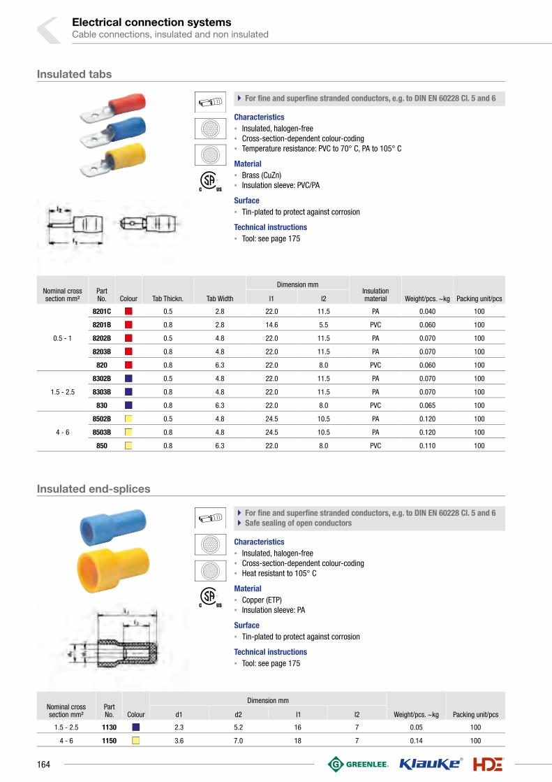
Electrical connection systemsCable connections, insulated and non insulated
Nominal cross section mm²
Part No. Colour Tab Thickn. Tab Width
Dimension mmInsulation material Weight/pcs. ~kg Packing unit/pcsl1 l2
0.5 - 1
8201C 0.5 2.8 22.0 11.5 PA 0.040 100
8201B 0.8 2.8 14.6 5.5 PVC 0.060 100
8202B 0.5 4.8 22.0 11.5 PA 0.070 100
8203B 0.8 4.8 22.0 11.5 PA 0.070 100
820 0.8 6.3 22.0 8.0 PVC 0.060 100
1.5 - 2.5
8302B 0.5 4.8 22.0 11.5 PA 0.070 100
8303B 0.8 4.8 22.0 11.5 PA 0.070 100
830 0.8 6.3 22.0 8.0 PVC 0.065 100
4 - 6
8502B 0.5 4.8 24.5 10.5 PA 0.120 100
8503B 0.8 4.8 24.5 10.5 PA 0.120 100
850 0.8 6.3 22.0 8.0 PVC 0.110 100
Nominal cross section mm²
Part No. Colour
Dimension mm
Weight/pcs. ~kg Packing unit/pcsd1 d2 l1 l2
1.5 - 2.5 1130 2.3 5.2 16 7 0.05 100
4 - 6 1150 3.6 7.0 18 7 0.14 100
Insulated tabs
` For fine and superfine stranded conductors, e.g. to DIN EN 60228 Cl. 5 and 6
Characteristics▪ Insulated, halogen-free▪ Cross-section-dependent colour-coding▪ Temperature resistance: PVC to 70° C, PA to 105° C
Material▪ Brass (CuZn)▪ Insulation sleeve: PVC/PA
Surface▪ Tin-plated to protect against corrosion
Technical instructions▪ Tool: see page 175
Insulated end-splices
` For fine and superfine stranded conductors, e.g. to DIN EN 60228 Cl. 5 and 6` Safe sealing of open conductors
Characteristics▪ Insulated, halogen-free▪ Cross-section-dependent colour-coding▪ Heat resistant to 105° C
Material▪ Copper (ETP)▪ Insulation sleeve: PA
Surface▪ Tin-plated to protect against corrosion
Technical instructions▪ Tool: see page 175
164

Nominal cross section mm²
Part No. Colour
Dimension mm
Weight/pcs. ~kg Packing unit/pcsd1 l1 l2
0.1 - 0.4 669 1.2 20 12 0.030 100
0.5 - 1 670 1.6 25 15 0.090 100
1.5 - 2.5 680 2.3 25 15 0.115 100
4 - 6 700 3.6 27 15 0.250 100
Nominal cross section mm²
Part No. Colour
Dimension mm
Weight/pcs. ~kg Packing unit/pcsd1 l1 l2
0.5 - 1 670WS 1.6 36 15 0.12 100
1.5 - 2.5 680WS 2.3 36 15 0.15 100
4 - 6 700WS 3.4 41 15 0.25 100
Insulated butt connectors
` For fine and superfine stranded conductors, e.g. to DIN EN 60228 Cl. 5 and 6` Simple and safe connecting owed to butt mark` Fast processing as no additional insulation of the crimped connection is
required
Characteristics▪ Insulated, halogen-free▪ Cross-section-dependent colour-coding▪ Heat resistant to 105° C
Material▪ Copper (ETP)▪ Insulation sleeve: PA
Surface▪ Tin-plated to protect against corrosion
Technical instructions▪ Tool: see page 175
Additional information▪ 0.1 - 0.4 mm² not CSA-tested
Insulated butt connectors with heat shrink insulation
` For fine and superfine stranded conductors, e.g. to DIN EN 60228 Cl. 5 and 6` Simple and safe processing due to butt mark` Fast processing as no additional insulation of the crimped connection is
required
Characteristics▪ Insulated, halogen-free▪ Cross-section-dependent colour-coding▪ Special crimping tool required▪ Heat resistant to 105° C
Material▪ Copper (ETP)▪ Insulation sleeve: PE
Surface▪ Tin-plated to protect against corrosion
Technical instructions▪ Tool: see page 175
165
1

Electrical connection systemsCable connections, insulated and non insulated
Nominal cross section mm²
Part No. Colour
Dimension mm
Weight/pcs. ~kg Packing unit/pcsd1 l1 l2
0.1 - 0.4 769 1.2 13 5 0.020 100
0.5 - 1 770 1.6 17 7 0.030 100
1.5 - 2.5 780 2.3 17 7 0.035 100
4 - 6 790 3.6 21 7 0.105 100
Insulated parallel connectors
` For fine and superfine stranded conductors, e.g. to DIN EN 60228 Cl. 5 and 6` Fast processing as no additional insulation of the crimped connection is
required
Characteristics▪ Insulated, halogen-free▪ Cross-section-dependent colour-coding▪ Heat resistant to 105° C
Material▪ Copper (ETP)▪ Insulation sleeve: PA
Surface▪ Tin-plated to protect against corrosion
Technical instructions▪ Tool: see page 175
Additional information▪ 0.1 - 0.4 mm² not CSA-tested
166

Nominal cross section mm²
Nominal size to
DIN Part No.Tab
Thickn. Tab Width
Dimension mmWeight/pcs. ~kg
Packing unit/pcsa1 a2 l1 l2 l3 s
0.5 - 1
--18251 0.5 2.8 5.0 2.8 12.5 5.0 3.3 0.30 0.025 100
18251A 0.8 2.8 5.5 2.5 12.5 5.0 3.3 0.30 0.025 100
B 2.8 - 1 18201A 0.8 2.8 5.5 2.5 14.0 6.3 3.3 0,35 0.025 100
-- 18202 0.5 4.8 6.0 3.4 15.6 6.0 3.8 0.35 0.050 100
4.8 - 1 18203 0.8 4.8 6.0 3.4 15.6 6.0 3.8 0.35 0.050 100
6.3 - 1 1720 0.8 6.3 8.5 4.5 19.0 7.4 4.0 0.45 0.085 100
1.5 - 2.54.8 - 2.5 18303 0.8 4.8 6.0 3.4 15.6 6.0 3.8 0.35 0.055 100
6.3 - 2.5 *1730 0.8 6.3 8.5 4.5 19.0 7.4 4.0 0.45 0.082 100
4 - 6 6.3 - 6 *1750 0.8 6.3 8.5 4.5 19.0 7.4 4.0 0.45 0.100 100
Nominal cross section mm² Part No.
Tab Thickn. Tab Width Hint
Dimension mmWeight/pcs. ~kg
Packing unit/pcsa1 a2 l1 l2 l3 s
0.5 - 1 18203AZ 0.8 4.8 6.0 3.4 15.6 7 6.0 0.38 0.09 100
1.5 - 2.518303AZ 0.8 4.8 6.0 3.4 15.6 7 6.0 0.38 0.09 100
1730AZ 0.8 6.3 * 8.5 4.5 19.2 8 7.5 0.38 0.13 100
Non-insulated receptacles
` For fine and superfine stranded conductors, e.g. to DIN EN 60228 Cl. 5 and 6
Characteristics▪ To DIN 46247, part 1 – 3 and similar versions▪ Improved contact properties due to grooved profile
Material▪ Brass (CuZn)
Surface▪ Tin-plated to protect against corrosion
Technical instructions▪ Tool: see page 176
Additional information▪ * = nickel-plated steel version also available, Part Number appendix “ST“
Non-insulated receptacles, multiple type
` For fine and superfine stranded conductors, e.g. to DIN EN 60228 Cl. 5 and 6
Characteristics▪ To DIN 46247, part 1 – 3 and similar versions▪ Improved contact properties due to grooved profile
Material▪ Brass (CuZn)
Surface▪ Tin-plated to protect against corrosion
Technical instructions▪ Tool: see page 176
Additional information▪ * = corresponds to DIN 46345
167
1

Electrical connection systemsCable connections, insulated and non insulated
Nominal cross
section mm²Part No. Tab Thickn. Tab Width
Dimension mmWeight/pcs.
~kgPacking unit/pcsa1 a2 l1 l2 l3 s
0.5 - 1 2720 0.8 6.3 8.5 4.5 19.2 7.4 7 0.38 0.070 100
1.5 - 2.5 2730 0.8 6.3 8.5 4.5 19.2 7.4 7 0.38 0.075 100
4 - 6 2750 0.8 6.3 8.5 4.5 19.2 7.4 7 0.38 0.090 100
Nominal cross section
mm²Part No. Tab Thickn. Tab Width Typ
Dimension mmWeight/pcs. ~kg
Packing unit/pcs a1 a2 l1 l2 l3 l4
0.5 - 1 3720 0.8 6.3 B 11.0 3.0 12.5 7.4 4.0 7.2 0.080 100
0.5 - 1.5 3725 0.8 6.3 C 7.5 4.0 11.00 7.4 4.0 7.2 0.085 100
1.5 - 2.5 3735 0.8 6.3 B 11.0 3.0 13.5 7.0 4.0 7.2 0.085 100
Non-insulated receptacles with locking latch
` For fine and superfine stranded conductors, e.g. to DIN EN 60228 Cl. 5 and 6
Characteristics▪ To DIN 46340, sheet 3▪ With latch to engage in housing▪ Improved contact properties due to grooved profile
Material▪ Brass (CuZn)
Surface▪ Tin-plated to protect against corrosion
Technical instructions▪ Tool: see page 176
Non-insulated receptacles with lateral conductor connector
` For fine and superfine stranded conductors, e.g. to DIN EN 60228 Cl. 5 and 6` Improved contact properties due to grooved profile
Material▪ Brass (CuZn)
Surface▪ Tin-plated to protect against corrosion
Technical instructions▪ Tool: see page 176
168

Nominal cross
section mm²
Nominal size to
DIN Part No.Tab
Thickn. Tab Width Typ Hint
Dimension mmWeight/pcs. ~kg
Packing unit/pcsa1 a2 d2 l1 l2
0.5 - 1
2235 0.8 2.8 A * 6.0 3.2 1.30 22.5 12.7 0.045 100
46343 B6.3 - 1
2220 0.8 6.3 A 8.2 4.0 1.65 28.0 16.0 0.085 100
1.5 - 2.5
46248 A6.3 - 2.5
1830 0.8 6.3 B 9.0 4.5 1.65 20.0 8.0 0.065 100
46343 B6.3 - 2.5
2230 0.8 6.3 A 8.2 4.0 1.65 28.0 16.0 0.090 100
4 - 646343
B6.3 - 62250 0.8 6.3 A 8.2 4.0 1.65 28.0 16.0 0.100 100
Nominal cross section
mm²Nominal
size to DIN Part No. Colour Typ
Dimension mmInsulation material for item
Weight/pcs. ~kg
Packing unit/pcsb1 l h1
0.5 - 1 2.8 2755 A 6.5 20.0 4.0 PE 18251,18251A, 18201A 0.015 100
0.5 - 1.54.8
2760 A 7.0 20.0 5.0 PE 18202,18203 0.015 100
1.5 - 2.5 2765 A 9.5 20.0 5.5 PE 18302,18303 0.025 100
see next page
Non-insulated tabs
` For fine and superfine stranded conductors, e.g. to DIN EN 60228 Cl. 5 and 6` Improved contact properties due to grooved profile
Material▪ Brass (CuZn)
Surface▪ Tin-plated to protect against corrosion
Technical instructions▪ Tool: see page 176
Additional information▪ * = dimensions in the plug sector to DIN 46244
Insulation sleeves
` For non-insulated tabs` Perfectly-matched to the different versions
Characteristics▪ For post-insulation of crimped non-insulated receptacles
Material▪ PA / PE / PVC
169
1

Electrical connection systemsCable connections, insulated and non insulated
Nominal cross section
mm²Nominal
size to DIN Part No. Colour Typ
Dimension mmInsulation material for item
Weight/pcs. ~kg
Packing unit/pcsb1 l h1
0.5 - 2.5
6.3
2770 A 12.5 23.0 8.5 PE 1720,1730 0.035 100
2775 A 9.5 25.0 5.0 PE 1820,1830 0.030 100
0.5 - 4 2780 A 9.5 25.0 6.0 PE1720,1730,1820,1830 0.030 100
0.5 - 6
2785 B 9.2 24.5 5.6 PA1720,1730,1750,2720,2730,2750 0.055 100
2790 C 13.5 15.0 3.1 PVC3720,3725,
3735 0.060 100
Nominal size to DIN Part No.
Tab Thickn. Tab Width Typ
Dimension mmWeight/pcs. ~kg
Packing unit/pcsb1 d2 l2 l3 l4 w
--
2040 0.8 2.8 A 5.0 3.2 5.5 6.5 -- 60° 0.040 100
2045 0.8 6.3 A 10.0 4.3 8.0 10.0 -- 45° 0.160 100
2060 0.8 6.3 B 8.0 4.3 8.0 8.0 10.7 30° 0.085 100
2070 0.8 6.3 B 8.0 3.2 8.0 8.0 10.7 45° 0.085 100
2075 0.8 6.3 B 8.0 4.1 8.0 8.0 10.7 45° 0.085 100
B 6.3 - 0.8 2080 0.8 6.3 B 8.0 4.3 8.0 8.5 10.7 45° 0.085 100
--
2083 0.8 6.3 B 8.0 5.3 8.0 8.5 10.7 45° 0.080 100
2090 0.8 6.3 B 8.0 5.3 8.0 8.0 10.7 45° 0.080 100
2100 0.8 6.3 B 7.5 2.5 8.0 5.7 11.5 90° 0.075 100
2105 0.8 6.3 B 8.0 3.2 8.0 8.0 11.5 90° 0.085 100
C 6.3 - 0.8 2115 0.8 6.3 B 8.0 4.3 8.0 8.5 11.5 90° 0.090 100
Non-insulated tabs, angled version
Characteristics▪ To DIN 46342, part 1 and similar versions▪ Dimensions in the plug sector to DIN 46244
Material▪ Brass (CuZn)
Surface▪ Tin-plated to protect against corrosion
Insulation sleeves
170

Nominal size to DIN Part No. Tab Thickn. Tab Width Typ
Dimension mmWeight/pcs.
~kgPacking unit/pcsb1 d2 l1 l2 s
-- 2123 0.8 2.8 A 4.5 3.1 13.0 5.5 0.8 0.028 100
A 6.3 - 0.8 2140 0.8 6.3 A 8.0 4.3 19.0 8.0 0.8 0.086 100
-- 2145 0.8 6.3 A 8.0 5.3 19.0 8.0 0.8 0.080 100
Part No.
Tab Thickn. Tab Width Typ
Dimension mmWeight/pcs. ~kg
Packing unit/pcsb1 b2 b3 l1 l2 l3 l4 s
2010 0.8 2.8 A -- -- -- 10.5 6.5 -- -- 0.8 0.015 100
2020 0.5 2.8 C 1.0 5 -- -- 7.1 8 13.4 0.5 0.025 100
2025 0.8 2.8 C 1.0 5 -- -- 7.1 8 13.4 0.8 0.040 100
2030 0.8 6.3 D 3.5 5 6.4 16.0 8.0 4 12.0 0.8 0.065 100
2035 0.8 6.3 E 3.8 5 6.2 16.0 8.0 3 12.0 0.8 0.085 100
Non-insulated tabs, straight version
Characteristics▪ To DIN 46342, part 1 and similar versions▪ Dimensions in the plug sector to DIN 46244
Material▪ Brass (CuZn)
Surface▪ Tin-plated to protect against corrosion
Non-insulated tabs for soldering
` Material used offers very good soldering characteristics
Characteristics▪ Dimensions in the plug sector to DIN 46244▪ For soldering in printed circuits
Material▪ Brass (CuZn)
Surface▪ Tin-plated to protect against corrosion
171
1

Electrical connection systemsCable connections, insulated and non insulated
Part No.
Tab Thickn.
Tab Width Typ
Dimension mmWeight/pcs. ~kg
Packing unit/pcs a1 b2 b3 l1 l2 l3 h w s
735 0.8 2.8 A 5 3.2 3.1 16.0 6.7 -- -- -- 0.38 0.060 100
755 0.8 4.8 C -- 4.4 -- 20.0 7.0 7.0 8.0 -- 0.38 0.155 100
725 0.8 6.3 D -- -- -- -- 8 7.5 -- 15° 0.38 0.115 100
775 0.8 6.3 C -- -- -- 20.5 12 7.5 9.6 -- 0.38 0.200 100
Part No. Tab Thickn. Tab Width Poles
Dimension mmInsulation material
Bolt size mmWeight/pcs. ~kg
Packing unit/pcsb l h s Distance Diameter
Tab Width 2.8 mm
8101 0.8 2.8 1 7.5 35 5.5 0.8 PVC -- -- 0.2 100
8102 0.8 2.8 2 15.0 35 5.5 0.8 PVC -- 2.7 0.3 50
81012 0.8 2.8 12 88.0 35 5.5 0.8 PVC 75 2.7 1.6 10
Tab Width 4.8 mm
8051 0.8 4.8 1 12.5 28 6.6 0.8 PVC -- -- 0.25 100
8052 0.8 4.8 2 25.0 28 6.6 0.8 PVC -- 3.2 0.50 50
80512 0.8 4.8 12 142.0 28 6.6 0.8 PVC 120 3.2 2.80 10
Tab Width 6.3 mm
8001 0.8 6.3 1 12.5 28 6.6 0.8 PVC -- -- 0.30 100
8002 0.8 6.3 2 25.0 28 6.6 0.8 PVC -- 3.7 0.55 50
80012 0.8 6.3 12 142.0 28 6.6 0.8 PVC 120 3.7 3.20 10
Non-insulated multiple tabs
Characteristics▪ Dimensions in the plug sector to DIN 46244
Material▪ Brass (CuZn)
Surface▪ Tin-plated to protect against corrosion
Flexible connector, tab width 2.8 mm, 4.8 mm and 6.3 mm
` No additional insulation required
Characteristics▪ With tabs 2.8, 4.8 or 6.3 x 0.8 mm▪ 1, 2 and 12-poles▪ Further poles on request
172

Part No. Tab Thickn. Tab Width Poles
Dimension mmInsulation material
Bolt size mmWeight/pcs. ~kg
Packing unit/pcsb l h s Distance Diameter
8011 0.8 6.3 and 2 x 2.8 1 10.0 50 7.5 0.8 PA -- -- 0.25 100
8012 0.8 6.3 and 2 x 2.8 2 22.5 50 7.5 0.8 PA -- 3.1 0.50 50
80112 0.8 6.3 and 2 x 2.8 12 147.5 50 7.5 0.8 PA 125 3.1 3.10 10
Part No. Tab Thickn. Tab Width Poles
Dimension mmInsulation material
Bolt size mmWeight/pcs. ~kg
Packing unit/pcsb l h s Distance Diameter
8151 0.8 2.8 1 12.5 28 7 0.8 PVC -- -- 0.25 100
81512 0.8 2.8 12 147.0 28 7 0.8 PVC 123 3.2 2.80 10
Polyamide connector, tab width 2.8 and 6.3 mm
` No additional insulation required
Characteristics▪ With tabs 2.8 x 0.8 mm and 6.3 x 0.8 mm▪ 1, 2 and 12-poles▪ Further poles on request
Flexible circuit distributor, tab width 2.8 mm
` No additional insulation required
Characteristics▪ With tabs 2.8 x 0.8 mm▪ 1 and 12-poles▪ Further poles on request
173
1

Electrical connection systemsCable connections, insulated and non insulated
Part No.
Tab Thickn. Tab Width Typ
Dimension mmInsulation material
Weight/pcs. ~kg
Packing unit/pcs b b1 b2 l l1 h s
816 0.8 6.3 A 21 11.3 9 53 15 7.5 0.8 PVC 0.60 10
817 0.8 6.3 B 20 11.3 9 51 13 7.0 0.8 PVC 0.65 10
Flexible circuit distributor, tab width 6.3 mm
` No additional insulation required
Characteristics▪ With tabs 6.3 x 0.8 mm
174

Tool application chart
Insulated cable connections
Mechanical crimping tools
0.1-1 K80 221
0.5-2.5 K81 222
0.5-6 K82 222
Mechanical, electrical, pneumatic crimping tools with interchangeable die / head
0.1-1 KP1 +KP80 240
KP1L +KP80 240
0.5-2.5 KP1 +KP81 240
KP1L +KP81 240
0.5-6 K50 244 327
EK50ML 254 327
4-6 KP1 +KP83 240
KP1L +KP83 240
Battery powered crimping tools
0.1-1 EKP1ML +KP80 260
0.5-2.5 EKP1ML +KP81 260
0.5-6 EK1550ML 258 327
4-6 EKP1ML +KP83 260
Mechanical, electrical, pneumatic crimping tools with interchangeable die / head
0.5-6 K50 244 327
EK50ML 254 327
Battery powered crimping tools
0.5-6 EK1550ML 258 327
Tool application chart
Butt connectors with heat shrink insulation
Tool type
Crimping range corresponds to nominal cross-section mm²
Crimping Tool Catalogue page
Crimp profilePart No.Crimping head / adapter Crimping Tool Crimping die
Tool type
Crimping range corresponds to nominal cross-section mm²
Crimping Tool Catalogue page
Crimp profilePart No.Crimping head / adapter Crimping Tool Crimping die
175
1

Electrical connection systemsCable connections, insulated and non insulated
Mechanical crimping tools
0.1-1 K572 224
K67 225
0.5-2.5 K582 224
K65 226
0.5-6 K592 225
K60 223
Mechanical, electrical, pneumatic crimping tools with interchangeable die / head
0.25-6 K50 244 327
EK50ML 254 327
Battery powered crimping tools
0.25-6 EK1550ML 258 327
Mechanical crimping tools
3720, 3735 K63 226
3725 K64 227
Mechanical, electrical, pneumatic crimping tools with interchangeable die / head
3720, 3735 K50 244 327
EK50ML 254 327
SKP6 242
3725 K50 244 327
EK50ML 254 327
SKP6 242
Battery powered crimping tools
3720, 3735 EK1550ML 258 327
3725 EK1550ML 258 327
Tool application chart
Tool application chart
Non-insulated receptacles, straight type
Non-insulated receptacles, with lateral conductor connector
Tool type
Crimping range corresponds to nominal cross-section mm²
Crimping Tool Catalogue page
Crimp profilePart No.Crimping head / adapter Crimping Tool Crimping die
Tool type
Crimping range corresponds to nominal cross-section mm²
Crimping Tool Catalogue page
Crimp profilePart No.Crimping head / adapter Crimping Tool Crimping die
176

177
1

Electrical connection systems
PRACTICAL - POCKET BOXES AND ASSORTMENT BOXESA good professional is always well sorted. The most important thing is the availability of
tool and connector material. In Klauke assortment boxes from robust metal, the tools
are supplied with matching cable lugs and connectors. Everything matches. Materials
and tools have their own space - clearly arranged and immediately to hand. The boxes
equip you for every application. On request, we can also stock them to suit your
individual needs.
In brief
`` Brings order to the workplace due to clearly arranged design
`` Everything to hand in one box
`` Stocked to suit your needs and numerous versions available
Assortments connection technology
178

` Our range, your order
We have already compiled an assortment for you.
We offer pre-filled boxes for various applications.
You can also fill the robust box yourself if you want.
◾ High-quality boxes made from plastic or metal
◾ Contains tool and connectors matched to one other
◾ Even if exposed to severe vibrations or dropped,
everything remains in the right compartment
◾ Boxes also available empty or custom-filled
` Practical and always to hand
With the practical pocket boxes, everything has its place and
is always to hand, on the go and in the workshop. Chute
openings for stackable pocket boxes simplify the removal of
cable end-sleeves.
◾ Cable-end sleeves with and without insulation always
to hand
◾ Practical chute opening for easy removal
◾ Stackable box
◾ Tough and impact-proof plastic
179
1

Electrical connection systemsAssortments
ST 23 B Pocket box with cable end-sleeves 0.25 - 1 mm²
` Pocket box made from impact-resistant plastic
Characteristics▪ Stackable and resealable
Item Part No.
Pocket box with cable end-sleeves 0.25 - 1 mm² to DIN 46228 part 1 ST23B
Scope of supply Description Quantity Page
ST23L Pocket box 1
695V Cable end-sleeve, 0.25 mm², 5 mm 1000 138
705V Cable end-sleeve, 0.34 mm², 5 mm, Cu tinned 1000 138
716V Cable end-sleeve, 0.75 mm², 6 mm 1000 138
71S6V Cable end-sleeve, 0.5 mm², 6 mm, Cu tinned 500 138
72S6V Cable end-sleeve, 1.0 mm², 6 mm 500 138
ST 21 B Pocket box with cable end-sleeves 0.5 - 2.5 mm²
` Pocket box made from impact-resistant plastic
Characteristics▪ Stackable and resealable
Item Part No.
Pocket box with cable end-sleeves 0.5 - 2.5 mm² to DIN 46228 part 1 ST21B
Scope of supply Description Quantity Page
ST21L Pocket box 1
71S6V Cable end-sleeve, 0.5 mm², 6 mm, Cu tinned 1000 138
716V Cable end-sleeve, 0.75 mm², 6 mm 500 138
72S6V Cable end-sleeve, 1.0 mm², 6 mm 500 138
727V Cable end-sleeve, 1.5 mm², 7 mm 500 138
737V Cable end-sleeve, 2.5 mm², 7 mm 500 138
ST 22 B Pocket box with cable end-sleeves 4 - 16 mm²
` Pocket box made from impact-resistant plastic
Characteristics▪ Stackable and resealable
Item Part No.
Pocket box with cable end-sleeves 4 - 16 mm² to DIN 46228 part 1 ST22B
Scope of supply Description Quantity Page
ST22L Pocket box 1
749V Cable end-sleeve, 4 mm², 9 mm 200 139
7512V Cable end-sleeve, 6 mm², 12 mm, Cu tinned 100 139
7612V Cable end-sleeve, 10 mm², 12 mm, Cu tinned 70 139
7712V Cable end-sleeve, 16 mm², 12 mm, Cu tinned 70 139
180

ST 15 B Pocket box with insulated twin cable end-sleeves 2 x 0.75 - 2 x 2.5 mm²
` Pocket box made from impact-resistant plastic
Characteristics▪ Stackable and resealable
Item Part No.
Pocket box with twin cable end-sleeves 2 x 0.75 - 2 x 2.5 mm² ST15B
Scope of supply Colour Description Quantity Page
ST15L Pocket box 1
8708 Insl. twin cable end-sleeve, 2 x 0.75 mm² 50 147
8718 Insl. twin cable end-sleeve, 2 x 1 mm² 50 147
8728 Insl. twin cable end-sleeve, 2 x 1.5 mm² 50 147
87310 Insl. twin cable end-sleeve, 2 x 2.5 mm² 50 147
ST 1 B pocket box with insl. cable end-sleeves 0.5 - 2.5 mm², DIN 46228 Part 4
` Pocket box made from impact-resistant plastic
Characteristics▪ Stackable and resealable
Item Part No.
Pocket box with insl. cable end-sleeves 0.5 - 2.5 mm², DIN 46228 Part 4, colour code 1 ST1B
Scope of supply Colour Description Quantity Page
ST1L Pocket box 1
169O Insl. cable end-sleeve, 0.5 mm², 14 mm 50 142
170W Insl. cable end-sleeve, 0.75 mm², 14.6 mm 100 143
171G Insl. cable end-sleeve, 1 mm², 14.6 mm 100 143
172RO Insl. cable end-sleeve, 1.5 mm², 14.6 mm 100 143
173B Insl. cable end-sleeve, 2.5 mm², 15.2 mm 50 143
ST 11 B pocket box with insl. cable end-sleeves 0.5 - 2.5 mm², DIN 46228 Part 4
` Pocket box made from impact-resistant plastic
Characteristics▪ Stackable and resealable
Item Part No.
Pocket box with insl. cable end-sleeves 0.5 - 2.5 mm², DIN 46228 Part 4 ST11B
Scope of supply Colour Description Quantity Page
ST11L Pocket box 1
4698 Insl. Cable end-sleeve, 0.5 mm², 14 mm 50 141
4708 Insl. cable end-sleeve, 0.75 mm², 14 mm 100 141
4718 Insl. cable end-sleeve, 1 mm², 14 mm 100 141
4728 Insl. cable end-sleeve, 1.5 mm², 14 mm 100 141
4738 Insl. cable end-sleeve, 2.5 mm², 14 mm 50 141
181
1

Electrical connection systemsAssortments
ST 31 B pocket box with insl. cable end-sleeves 0.5 - 2.5 mm², DIN 46228 Part 4, colour code 2
` Pocket box made from impact-resistant plastic
Characteristics▪ Stackable and resealable
Item Part No.
Pocket box with insl. cable end-sleeves 0.5 - 2.5 mm², DIN 46228 Part 4, colour code 2
ST31B
Scope of supply Colour Description Quantity Page
ST31L Pocket box 1
1698 Insl. cable end-sleeve, 0.5 mm², 13 mm 50 144
1708 Insl. cable end-sleeve, 0.75 mm², 13.5 mm 100 144
1718 Insl. cable end-sleeve, 1 mm², 13.5 mm 100 144
1728 Insl. cable end-sleeve, 1.5 mm², 13.5 mm 100 144
1738 Insl. cable end-sleeve, 2.5 mm², 14.5 mm 50 144
ST 12 B pocket box with insl. cable end-sleeves 4 - 16 mm², DIN 46228 Part 4
` Pocket box made from impact-resistant plastic
Characteristics▪ Stackable and resealable
Item Part No.
Pocket box with insl. cable end-sleeves 4 - 16 mm², DIN 46228 Part 4 ST12B
Scope of supply Colour Description Quantity Page
ST12L Pocket box 1
47410 Insl. cable end-sleeve, 4 mm², 17 mm 50 141
47512 Insl. cable end-sleeve, 6 mm², 20 mm 20 141
47612 Insl. cable end-sleeve, 10 mm², 22 mm 20 141
47712 Insl. cable end-sleeve, 16 mm², 24 mm 10 142
ST 2 B pocket box with insl. cable end-sleeves 4 - 16 mm², DIN 46228 Part 4, colour code 1
` Pocket box made from impact-resistant plastic
Characteristics▪ Stackable and resealable
Item Part No.
Pocket box with insl. cable end-sleeves 4 - 16 mm², DIN 46228 Part 4, colour code 1 ST2B
Scope of supply Colour Description Quantity Page
ST2L Pocket box 1
174GR Insl. cable end-sleeve, 4 mm², 16.5 mm 50 143
175S Insl. cable end-sleeve, 6 mm², 20 mm 20 143
176E Insl. cable end-sleeve, 10 mm², 21.5 mm 20 143
177GR Insl. cable end-sleeve, 16 mm², 22.2 mm 10 143
182

ST 32 B pocket box with insl. cable end-sleeves 4 - 16 mm², DIN 46228 Part 4, colour code 2
` Pocket box made from impact-resistant plastic
Characteristics▪ Stackable and resealable
Item Part No.
Pocket box with insl. cable end-sleeves 4 - 16 mm², DIN 46228 Part 4, colour code 2 ST32B
Scope of supply Colour Description Quantity Page
ST32L Pocket box 1
17410 Insl. cable end-sleeve, 4 mm², 16.5 mm 50 144
17512 Insl. cable end-sleeve, 6 mm², 20 mm 20 144
17612 Insl. cable end-sleeve, 10 mm², 21.5 mm 20 145
17712 Insl. cable end-sleeve, 16 mm², 23.5 mm 10 145
ST 3 B pocket box with insl. cable end-sleeves 0.25 - 1 mm², DIN 46228 Part 4, colour code 1
` Pocket box made from impact-resistant plastic
Characteristics▪ Stackable and resealable
Item Part No.
Pocket box with insl. cable end-sleeves 0.25 - 1 mm², DIN 46228 Part 4, colour code 1 ST3B
Scope of supply Colour Description Quantity Page
ST3L Pocket box 1
167H Insl. cable end-sleeve, 0.25 mm², 10.4 mm 30 142
168T Insl. cable end-sleeve, 0.34 mm², 10.4 mm 30 142
169O Insl. cable end-sleeve, 0.5 mm², 14 mm 30 142
170W Insl. cable end-sleeve, 0.75 mm², 14.6 mm 30 143
171G Insl. cable end-sleeve, 1 mm², 14.6 mm 30 143
ST 13 B pocket box with insl. cable end-sleeves 0.25 - 1 mm², DIN 46228 Part 4 & similar, colour code 1
` Pocket box made from impact-resistant plastic
Characteristics▪ Stackable and resealable
Item Part No.
Pocket box with insl. cable end-sleeves 0.25 - 1 mm², DIN 46228 Part 4 & similar, colour code 1
ST13B
Scope of supply Colour Description Quantity Page
ST13L Pocket box 1
167H Insl. cable end-sleeve, 0.25 mm², 10.4 mm 30 142
168T Insl. cable end-sleeve, 0.34 mm², 10.4 mm 30 142
4698 Insl. Cable end-sleeve, 0.5 mm², 14 mm 30 141
4708 Insl. cable end-sleeve, 0.75 mm², 14 mm 30 141
4718 Insl. cable end-sleeve, 1 mm², 14 mm 30 141
183
1

Electrical connection systemsAssortments
ST 33 B pocket box with insl. cable end-sleeves 0.25-1 mm², DIN 46228 Part 4 & similar, colour code 2
` Pocket box made from impact-resistant plastic
Characteristics▪ Stackable and resealable
Item Part No.
Pocket box with insl. cable end-sleeves 0.25 - 1 mm², DIN 46228 Part 4 & similar, colour code 2
ST33B
Scope of supply Colour Description Quantity Page
ST33L Pocket box 1
1676 Insl. cable end-sleeve, 0.25 mm², 11 mm 30 144
1686 Insl. cable end-sleeve, 0.34 mm², 11 mm 30 144
1698 Insl. cable end-sleeve, 0.5 mm², 13 mm 30 144
1708 Insl. cable end-sleeve, 0.75 mm², 13.5 mm 30 144
1718 Insl. cable end-sleeve, 1 mm², 13.5 mm 30 144
GR 4698 DO Pocket box with insulated cable end-sleeves 0.5 mm²
` Pocket box made from impact-resistant plastic
Characteristics▪ Stackable and resealable
Item Part No.
Pocket box with insulated cable end-sleeves 0.5 mm² to DIN 46228 part 4 GR4698DO
Scope of supply Colour Description Quantity Page
4698 Insl. Cable end-sleeve, 0.5 mm², 14 mm 1000 141
GR 4708 DO Pocket box with insulated cable end-sleeves 0.75 mm²
` Pocket box made from impact-resistant plastic
Characteristics▪ Stackable and resealable
Item Part No.
Pocket box with insulated cable end-sleeves 0.75 mm² DIN 46228 part 4 GR4708DO
Scope of supply Colour Description Quantity Page
4708 Insl. cable end-sleeve, 0.75 mm², 14 mm 1000 141
GR 4718 DO Pocket box with insulated cable end-sleeves 1 mm²
` Pocket box made from impact-resistant plastic
Characteristics▪ Stackable and resealable
Item Part No.
Pocket box with insulated cable end-sleeves 1 mm² DIN 46228 part 4 GR4718DO
Scope of supply Colour Description Quantity Page
4718 Insl. cable end-sleeve, 1 mm², 14 mm 1000 141
184

GR 4728 DO Pocket box with insulated cable end-sleeves 1.5 mm²
` Pocket box made from impact-resistant plastic
Characteristics▪ Stackable and resealable
Item Part No.
Pocket box with insulated cable end-sleeves 1.5 mm² DIN 46228 part 4 GR4728DO
Scope of supply Colour Description Quantity Page
4728 Insl. cable end-sleeve, 1.5 mm², 14 mm 1000 141
GR 4738 DO Pocket box with insulated cable end-sleeves 2.5 mm²
` Pocket box made from impact-resistant plastic
Characteristics▪ Stackable and resealable
Item Part No.
Pocket box with insulated cable end-sleeves 2.5 mm² DIN 46228 part 4 GR4738DO
Scope of supply Colour Description Quantity Page
4738 Insl. cable end-sleeve, 2.5 mm², 14 mm 1000 141
ST 5 L assortment of empty pocket boxes
` Pocket box made from impact-resistant plastic
Characteristics▪ Stackable and resealable
ItemPart No.
Assortment of pocket boxes ST5L
SK 30 B Steel assortment box with cable end-sleeves and crimping tool
` Hammer-tone finished assortment box` Ideal for workshop equipment
Item Dimension mm Part No.
Steel assortment box with cable end-sleeves and crimping tool
200 x 140 x 40 SK30B
Scope of supply Description Quantity Page
SK30L Steel carrying case 1 193
K48 Crimping tool for cable end-sleeves 0.14 - 2.5 mm² 1 212
716V Cable end-sleeve, 0.75 mm², 6 mm 1000 138
72S6V Cable end-sleeve, 1.0 mm², 6 mm 1000 138
727V Cable end-sleeve, 1.5 mm², 7 mm 1000 138
737V Cable end-sleeve, 2.5 mm², 7 mm 1000 138
185
1

Electrical connection systemsAssortments
SK 32 B Steel assortment box with cable end-sleeves and crimping tool
` Broad cable end-sleeve assortment appropriate crimping tool` Hammer-tone finished assortment box` Ideal for workshop equipment
Item Dimension mm Part No.
Steel assortment box with cable end-sleeves and crimping tool
285 x 155 x 45 SK32B
Scope of supply Description Quantity Page
SK32L Steel carrying case 1 193
K3 Crimping tool for cable end-sleeves 0.5 - 16 mm² 1 211
716V Cable end-sleeve, 0.75 mm², 6 mm 1000 138
72S6V Cable end-sleeve, 1.0 mm², 6 mm 1000 138
727V Cable end-sleeve, 1.5 mm², 7 mm 1000 138
737V Cable end-sleeve, 2.5 mm², 7 mm 500 138
749V Cable end-sleeve, 4 mm², 9 mm 500 139
7510V Cable end-sleeve, 6 mm², 10 mm 500 139
7618V Cable end-sleeve, 10 mm², 18 mm 250 139
7718V Cable end-sleeve, 16 mm², 18 mm 150 139
SK 45 B Steel assortment box with insl. cable end-sleeves and crimping tool
` Four of the most important insulated cable end-sleeve types in a steel carrying case including an appropriate crimping tool
` Hammer-tone finished assortment box` Ideal for workshop equipment
Item Dimension mm Part No.
Steel assortment box with insl. cable end-sleeves and crimping tool
200 x 140 x 40 SK45B
Scope of supply Colour Description Quantity Page
SK30L Steel carrying case 1 193
K48 Crimping tool for cable end-sleeves 0.14 - 2.5 mm² 1 212
4708 Insl. cable end-sleeve, 0.75 mm², 14 mm 300 141
4718 Insl. cable end-sleeve, 1 mm², 14 mm 300 141
4728 Insl. cable end-sleeve, 1.5 mm², 14 mm 300 141
4738 Insl. cable end-sleeve, 2.5 mm², 14 mm 200 141
186

SK 47 B Steel assortment box with insl. cable end-sleeves and crimping tool
` Flexible use due to large cross-sectional range` Hammer-tone finished assortment box` Ideal for workshop equipment
Item Dimension mm Part No.
Steel assortment box with insl. cable end-sleeves and crimping tool
285 x 155 x 45 SK47B
Scope of supply Colour Description Quantity Page
SK32L Steel carrying case 1 193
K3 Crimping tool for cable end-sleeves 0.5 - 16 mm² 1 211
4708 Insl. cable end-sleeve, 0.75 mm², 14 mm 200 141
4718 Insl. cable end-sleeve, 1 mm², 14 mm 200 141
4728 Insl. cable end-sleeve, 1.5 mm², 14 mm 200 141
4738 Insl. cable end-sleeve, 2.5 mm², 14 mm 200 141
47410 Insl. cable end-sleeve, 4 mm², 17 mm 100 141
47512 Insl. cable end-sleeve, 6 mm², 20 mm 100 141
47618 Insl. cable end-sleeve, 10 mm², 28 mm 100 141
47718 Insl. cable end-sleeve, 16 mm², 28 mm 50 142
SK 30/3 P Assortment box from plastic with insl. cable end-sleeves and tools
` With everything needed for conductor preparation` The exact-shaped foam inlays of the case prevent the contents slipping
even with severe impacts
Item Dimension mm Part No.
Plastic assortment box with insl. cable end-sleeves and tools 395 x 295 x 106 SK303P
Scope of supply Colour Description Quantity Page
K432 Automatic wire stripper K43/2 0.02 - 10 mm² 1 545
K303 Crimping tool for cable end-sleeves and twin cable end-sleeves 0.08 - 10 mm²
1 217
4698 Insl. Cable end-sleeve, 0.5 mm², 14 mm 400 141
4708 Insl. cable end-sleeve, 0.75 mm², 14 mm 400 141
4718 Insl. cable end-sleeve, 1 mm², 14 mm 400 141
4728 Insl. cable end-sleeve, 1.5 mm², 14 mm 400 141
4738 Insl. cable end-sleeve, 2.5 mm², 14 mm 200 141
47410 Insl. cable end-sleeve, 4 mm², 17 mm 200 141
47512 Insl. cable end-sleeve, 6 mm², 20 mm 100 141
47612 Insl. cable end-sleeve, 10 mm², 22 mm 100 141
187
1

Electrical connection systemsAssortments
SK 30/3 S Assortment box from plastic with insl. cable end-sleeves and crimping tool
` With everything needed for conductor preparation` The exact-shaped foam inlays of the case prevent the contents slipping
even with severe impacts
Item Dimension mm Part No.
Plastic assortment box with insl. cable end-sleeves and crimping tool
275 x 230 x 83 SK303S
Scope of supply Colour Description Quantity Page
K303 Crimping tool for cable end-sleeves and twin cable end-sleeves 0.08 - 10 mm²
1 217
4698 Insl. Cable end-sleeve, 0.5 mm², 14 mm 100 141
4708 Insl. cable end-sleeve, 0.75 mm², 14 mm 100 141
4718 Insl. cable end-sleeve, 1 mm², 14 mm 100 141
4728 Insl. cable end-sleeve, 1.5 mm², 14 mm 100 141
4738 Insl. cable end-sleeve, 2.5 mm², 14 mm 50 141
47410 Insl. cable end-sleeve, 4 mm², 17 mm 50 141
47512 Insl. cable end-sleeve, 6 mm², 20 mm 30 141
47612 Insl. cable end-sleeve, 10 mm², 22 mm 30 141
SK 43 NB Assortment box from plastic with insl. cable end-sleeves and tools
` With everything needed for conductor preparation` Ideal for workshop equipment
Item Dimension mm Part No.
Steel assortment box with insl. cable end-sleeves and tools 370 x 210 x 40 SK43NB
Scope of supply Colour Description Quantity Page
SK43L Steel carrying case 1 193
K432 Automatic wire stripper K43/2 0.02 - 10 mm² 1 545
K303 Crimping tool for cable end-sleeves and twin cable end-sleeves 0.08 - 10 mm²
1 217
4698 Insl. Cable end-sleeve, 0.5 mm², 14 mm 500 141
4708 Insl. cable end-sleeve, 0.75 mm², 14 mm 500 141
4718 Insl. cable end-sleeve, 1 mm², 14 mm 400 141
4728 Insl. cable end-sleeve, 1.5 mm², 14 mm 400 141
4738 Insl. cable end-sleeve, 2.5 mm², 14 mm 300 141
47410 Insl. cable end-sleeve, 4 mm², 17 mm 100 141
47512 Insl. cable end-sleeve, 6 mm², 20 mm 100 141
47612 Insl. cable end-sleeve, 10 mm², 22 mm 100 141
188

SK 65 B Assortment box from steel with tubular cable lugs and crimping tool
` Hammer-tone finished assortment box` Ideal for workshop equipment
Characteristics▪ Sturdy steel carrying case with lock and handle
Item Dimension mm Part No.
Steel assortment box with tubular cable lugs "standard type" and crimping tool K05
400 x 250 x 50 SK65B
Scope of supply Description Quantity Page
SK65L Steel carrying case 1 195
K05 Crimping tool for tubular cable lugs and connectors, standard type 6 - 50 mm²
1 235
1R6 Tubular cable lug without inspection hole, 6 mm², M6, Cu tinned
25 14
1R8 Tubular cable lug without inspection hole, 6 mm², M8, Cu tinned
25 14
2R6 Tubular cable lug without inspection hole, 10 mm², M6, Cu tinned
25 14
2R8 Tubular cable lug without inspection hole, 10 mm², M8, Cu tinned
25 14
3R8 Tubular cable lug without inspection hole, 16 mm², M8, Cu tinned
25 14
3R10 Tubular cable lug without inspection hole, 16 mm², M10, Cu tinned
25 14
4R8 Tubular cable lug without inspection hole, 25 mm², M8, Cu tinned
25 14
4R10 Tubular cable lug without inspection hole, 25 mm², M10, Cu tinned
25 14
5R8 Tubular cable lug without inspection hole, 35 mm², M8, Cu tinned
20 14
5R10 Tubular cable lug without inspection hole, 35 mm², M10, Cu tinned
20 14
6R10 Tubular cable lug without inspection hole, 50 mm², M10, Cu tinned
20 15
6R12 Tubular cable lug without inspection hole, 50 mm², M12, Cu tinned
20 15
189
1
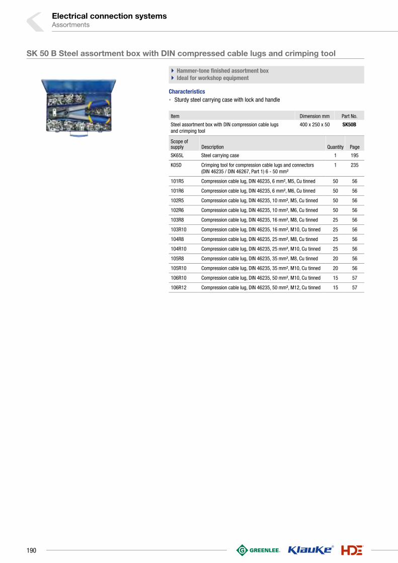
Electrical connection systemsAssortments
SK 50 B Steel assortment box with DIN compressed cable lugs and crimping tool
` Hammer-tone finished assortment box` Ideal for workshop equipment
Characteristics▪ Sturdy steel carrying case with lock and handle
Item Dimension mm Part No.
Steel assortment box with DIN compression cable lugs and crimping tool
400 x 250 x 50 SK50B
Scope of supply Description Quantity Page
SK65L Steel carrying case 1 195
K05D Crimping tool for compression cable lugs and connectors (DIN 46235 / DIN 46267, Part 1) 6 - 50 mm²
1 235
101R5 Compression cable lug, DIN 46235, 6 mm², M5, Cu tinned 50 56
101R6 Compression cable lug, DIN 46235, 6 mm², M6, Cu tinned 50 56
102R5 Compression cable lug, DIN 46235, 10 mm², M5, Cu tinned 50 56
102R6 Compression cable lug, DIN 46235, 10 mm², M6, Cu tinned 50 56
103R8 Compression cable lug, DIN 46235, 16 mm², M8, Cu tinned 25 56
103R10 Compression cable lug, DIN 46235, 16 mm², M10, Cu tinned 25 56
104R8 Compression cable lug, DIN 46235, 25 mm², M8, Cu tinned 25 56
104R10 Compression cable lug, DIN 46235, 25 mm², M10, Cu tinned 25 56
105R8 Compression cable lug, DIN 46235, 35 mm², M8, Cu tinned 20 56
105R10 Compression cable lug, DIN 46235, 35 mm², M10, Cu tinned 20 56
106R10 Compression cable lug, DIN 46235, 50 mm², M10, Cu tinned 15 57
106R12 Compression cable lug, DIN 46235, 50 mm², M12, Cu tinned 15 57
190

MK 230 B 507 Steel assortment box with insl. cable connections and crimping tool
` Hammer-tone finished assortment box` Ideal for workshop equipment
Item Dimension mm Part No.
Steel assortment box with insl. cable connections and crimping tool
366 x 230 x 51 MK230B507
Scope of supply Colour Description Quantity Page
MK230L Steel carrying case 1 194
K507 Crimping tool with replaceable dies 1 243
6204 Insl. solderless terminal M4, 0.5 - 1 mm² 50 156
6205 Insl. solderless terminal M5, 0.5 - 1 mm² 50 156
6206 Insl. solderless terminal M6, 0.5 - 1 mm² 50 156
6304 Insl. solderless terminal M4, 1.5 - 2.5 mm² 50 156
6305 Insl. solderless terminal M5, 1.5 - 2.5 mm² 50 156
6306 Insl. solderless terminal M6, 1.5 - 2.5 mm² 50 156
670 Insl. butt connector, 0.5 - 1 mm² 50 165
680 Insl. butt connector, 1.5 - 2.5 mm² 50 165
705 Insl. pin terminal, 0.5 - 1 mm², 22 mm 50 158
710 Insl. pin terminal, 1.5 - 2.5 mm², 23 mm 50 158
730 Insl. receptacle 6.3 x 0.8 mm, 1.5 - 2.5 mm² 50 161
830 Insl. tab 6.3 x 0.8 mm, 1.5 - 2.5 mm² 50 164
620C4 Insl. solderless terminal M4, 0.5 - 1 mm² 50 157
630C4 Insl. solderless terminal M4, 1.5 - 2.5 mm² 50 157
715 Insl. pin terminal, 0.1 - 0.4 mm², 26 mm 25 158
700 Insl. butt connector, 4 - 6 mm² 25 165
6505 Insl. solderless terminal M5, 4 - 6 mm² 25 156
6506 Insl. solderless terminal M6, 4 - 6 mm² 25 156
650C6 Insl. solderless terminal M6, 4 - 6 mm² 25 157
191
1

Electrical connection systemsAssortments
SK 82 P Assortment box from plastic with insl. cable connections and tools
` With everything needed for conductor preparation` The exact-shaped foam inlays of the case prevent the contents slipping
even with severe impacts
Item Dimension mm Part No.
Plastic assortment box with insl. cable connections and tools 395 x 295 x 106 SK82P
Scope of supply Colour Description Quantity Page
K432 Automatic wire stripper K43/2 0.02 - 10 mm² 1 545
K82A Crimping tool for insulated cable connections 0.5 - 6 mm²
1 222
6204 Insl. solderless terminal M4, 0.5 - 1 mm² 50 156
6205 Insl. solderless terminal M5, 0.5 - 1 mm² 50 156
670 Insl. butt connector, 0.5 - 1 mm² 50 165
720 Insl. receptacle 6.3 x 0.8 mm, 0.5 - 1 mm² 50 161
6304 Insl. solderless terminal M4, 1.5 - 2.5 mm² 50 156
6305 Insl. solderless terminal M5, 1.5 - 2.5 mm² 50 156
680 Insl. butt connector, 1.5 - 2.5 mm² 50 165
730 Insl. receptacle 6.3 x 0.8 mm, 1.5 - 2.5 mm² 50 161
6505 Insl. solderless terminal M5, 4 - 6 mm² 20 156
6506 Insl. solderless terminal M6, 4 - 6 mm² 20 156
700 Insl. butt connector, 4 - 6 mm² 20 165
715 Insl. pin terminal, 0.1 - 0.4 mm², 26 mm 20 158
620C4 Insl. solderless terminal M4, 0.5 - 1 mm² 20 157
630C4 Insl. solderless terminal M4, 1.5 - 2.5 mm² 20 157
705 Insl. pin terminal, 0.5 - 1 mm², 22 mm 20 158
710 Insl. pin terminal, 1.5 - 2.5 mm², 23 mm 20 158
SK 82 S Assortment box from plastic with insl. cable connections and crimping tool
` The exact-shaped foam inlays of the case prevent the contents slipping even with severe impacts
Item Part No.
Plastic assortment box with insl. cable connections and crimping tool SK82S
Scope of supply Colour Description Quantity Page
K82A Crimping tool for insulated cable connections 0.5 - 6 mm²
1 222
6204 Insl. solderless terminal M4, 0.5 - 1 mm² 20 156
6205 Insl. solderless terminal M5, 0.5 - 1 mm² 20 156
670 Insl. butt connector, 0.5 - 1 mm² 20 165
720 Insl. receptacle 6.3 x 0.8 mm, 0.5 - 1 mm² 20 161
6304 Insl. solderless terminal M4, 1.5 - 2.5 mm² 20 156
680 Insl. butt connector, 1.5 - 2.5 mm² 20 165
730 Insl. receptacle 6.3 x 0.8 mm, 1.5 - 2.5 mm² 20 161
6305 Insl. solderless terminal M5, 1.5 - 2.5 mm² 20 156
192

SK 30 L Steel carrying case
` Hammer-tone finished assortment box
Characteristics▪ 4 small and 1 large additional compartments with lock
Suitable for▪ For optional storage of crimping tools type K1, K4, K46 and K48
ItemDimension
mm Weight kgPart No.
Steel carrying case 200 x 140 x 40
1.2 SK30L
SK 32 L Steel carrying case
` Hammer-tone finished assortment box
Characteristics▪ 8 small and 1 large additional compartments with lock
Suitable for▪ For optional storage of crimping tools type K3 and K35
ItemDimension
mm Weight kgPart No.
Steel carrying case 285 x 155 x 45
1.3 SK32L
SK 4 L Steel carrying case
` Hammer-tone finished assortment box
Characteristics▪ 6 small and 1 large additional compartments with lock
Suitable for▪ For optional storage of crimping tools type K02, K2, K16, K25, K28 and K29
ItemDimension
mm Weight kgPart No.
Steel carrying case 370 x 160 x 40
1.4 SK4L
SK 43 L Steel carrying case
` Hammer-tone finished assortment box
Characteristics▪ 8 small and 2 large additional compartments with lock
Suitable for▪ For storage of crimping tool K 32 and wire stripper K 41
ItemDimension
mm Weight kgPart No.
Steel carrying case 370 x 210 x 40
1.9 SK43L
193
1

Electrical connection systemsAssortments
MK 55 Steel carrying case
` Hammer-tone finished assortment box
Characteristics▪ 8 small and 1 large additional compartments with lock
Suitable for▪ For storage of 8 pairs of dies and crimping tool K50
ItemDimension
mm Weight kgPart No.
Steel carrying case 245 x 130 x 37
0.7 MK55
MK 210 L Steel carrying case
` Hammer-tone finished assortment box
Characteristics▪ 4 small and 1 large additional compartments with lock
Suitable for▪ For storage of crimping tools K 10 or K 82
ItemDimension
mm Weight kgPart No.
Steel carrying case 250 x 155 x 40
1.0 MK210L
MK 220 L Steel carrying case
` Hammer-tone finished assortment box
Characteristics▪ 8 small and 1 large additional compartments with lock
Suitable for▪ For storage of crimping tools K 10 or K 82
ItemDimension
mm Weight kgPart No.
Steel carrying case 370 x 160 x 40
1.4 MK220L
MK 230 L Steel carrying case
` Hammer-tone finished assortment box
Characteristics▪ 19 small and 1 large additional compartments with lock and handle
Suitable for▪ For storage of crimping tools K 10 or K 82
ItemDimension
mm Weight kgPart No.
Steel carrying case 366 x 230 x 51
2.4 MK230L
194

SK 65 L Steel carrying case
` Hammer-tone finished assortment box
Characteristics▪ 12 small and 1 large additional compartments with lock and handle
Suitable for▪ For storage of crimping tools type K 05, K 05 BC, K 35/4
ItemDimension
mm Weight kgPart No.
Steel carrying case 400 x 250 x 50
2.3 SK65L
MK 18 Steel carrying case
` Hammer-tone finished assortment box
Characteristics▪ 34 small and 1 large additional compartments with lock and handle
Suitable for▪ For storage of 34 pairs of dies and crimping tool K 18
ItemDimension
mm Weight kgPart No.
Steel carrying case 605 x 300 x 50
4.6 MK18
MK 22 Steel carrying case
` Hammer-tone finished assortment box
Characteristics▪ 17 small and 1 large additional compartments with lock and handle
Suitable for▪ For storage of 17 pairs of dies and crimping tool K 22
ItemDimension
mm Weight kgPart No.
Steel carrying case 600 x 220 x 65
3.5 MK22
KKPE Plastic case
Characteristics▪ With lock and handle
Suitable for▪ For storing complete crimping die sets
Item Part No.
Plastic case KKPE
Plastic case KKPEH25
Plastic case for crimping dies of series 13 KKPE13
195
1

Electrical connection systemsAssortments
MK/KP 1 Plastic case
Characteristics▪ With lock and handle
Suitable for▪ For storage of crimping tools KP1 and KP1L and 10 crimping heads
of the Klauke Pro Series
ItemDimension
mm Weight kgPart No.
Plastic case 395 x 295 x 106 1.0 MKKP1
MKU Steel carrying case with wheels
` Hammer-tone finished assortment box
Characteristics▪ With additional compartment for dies with lock and handle
Suitable for▪ For storage of hydraulic crimping tools HK12/2, HK25/2 or HK45
ItemDimension
mm Weight kgPart No.
Steel carrying case 810 x 310 x 210 10.0 MKU
TT2 Carrying case
Suitable for▪ For storing all crimping and cutting heads (excluding SDK 105, SDK 120 and PK1000)
Item Weight kg Part No.
Carrying bag 0.48 TT2
TT4 Carrying case
Suitable for▪ For storage of cutting heads SDK 105 and SDK 120
Item Weight kg Part No.
Carrying bag 0.73 TT4
196

197
1

Electrical connection systems
SYSTEMATIC ORDER - L-BOXX FROM BS SYSTEMSWe must have order, especially when on the go. L-Boxx from BS Systems is a well
thought out arrangement system for safely transporting your Klauke tool and
connectors no matter what. Klauke products are safely stowed in the L-Boxx -
matched to your individual equipment. Keep the overview!
In brief
`` Available in various sizes
`` Maximum protection due to shock and impact resistant materials
`` Easy to transport with practical handle on the cover and the sides
`` Simple stacking of several boxes thanks to click system
L-BOXXes
198

` Everything practically packed
The L-Box doesn’t just stow your tools - they also assign them
exactly the right storage location. Trust in our Klauke system of
pre-stocked boxes for various applications.
◾ Pre-stocked boxes equipped to your needs
◾ Choice for differing areas of applications
◾ Everything to hand in one box
` Sorted on the go
Do you need your toolboxes on the go? With the TÜV-tested
Sortimo vehicle equipment, all Klauke tools and ranges can be
systematically and safely transported in L-Boxxes.
◾ Quickly located thanks to the Sortimo system overview
◾ Avoid injury by securing the boxes against accidents
and braking actions
◾ Short searching time for efficient operations
` Large or small?
The L-Boxx provides the right tool every time. Select what you
need from the broad range of sizes. The boxes are always
shock and impact resistant and and can be stacked without
risk of slipping due to a click system.
◾ Available in various sizes
◾ Shock and impact resistant
◾ Easy to transport with practical handles on the cover
and on the sides
◾ Safe transportation and storage due to click system
199
1

L-BOXX 65B from plastic with standard equipment for electrical installations
` Comprehensive equipment for conductor preparation, comprising cable cutter, cable knife, crimping tool and connectors
Characteristics▪ Manufactured from shock and impact resistant ABS plastic, very robust,
100 kg capacity▪ Stackable using an Easy-Click system, which allows easy opening and closing
Item Dimension mm Part No.
L-BOXX from plastic with standard equipment for electrical installations
442 x 357 x 117 LBOXX65B
Scope of supply Description Quantity Page
K05 Crimping tool for tubular cable lugs and connectors, standard type 6 - 50 mm²
1 235
K100 Hand-operated cutting tool for Cu and Al cables to 14 mm dia. 1 364
KL740416 Cable knife, without blade 4 - 16 mm dia. 1 547
1R6 Tubular cable lug without inspection hole, 6 mm², M6, Cu tinned
25 14
1R8 Tubular cable lug without inspection hole, 6 mm², M8, Cu tinned
25 14
2R6 Tubular cable lug without inspection hole, 10 mm², M6, Cu tinned
25 14
2R8 Tubular cable lug without inspection hole, 10 mm², M8, Cu tinned
25 14
3R10 Tubular cable lug without inspection hole, 16 mm², M10, Cu tinned
25 14
4R8 Tubular cable lug without inspection hole, 25 mm², M8, Cu tinned
20 14
4R10 Tubular cable lug without inspection hole, 25 mm², M10, Cu tinned
20 14
5R8 Tubular cable lug without inspection hole, 35 mm², M8, Cu tinned
20 14
5R10 Tubular cable lug without inspection hole, 35 mm², M10, Cu tinned
20 14
6R10 Tubular cable lug without inspection hole, 50 mm², M10, Cu tinned
15 15
LBOXX102LFG L-BOXX with front handle 1
Electrical connection systemsL-BOXXes
200

L-BOXX 50B from plastic with standard equipment for electrical installations
` Comprehensive equipment for conductor preparation, comprising cable cutter, cable knife, crimping tool and connectors
Characteristics▪ Manufactured from shock and impact resistant ABS plastic, very robust,
100 kg capacity▪ Stackable using an Easy-Click system, which allows easy opening and closing
Item Dimension mm Part No.
L-BOXX from plastic with standard equipment for electrical installations
442 x 357 x 117 LBOXX65B
Scope of supply Description Quantity Page
K05D Crimping tool for compression cable lugs and connectors (DIN 46235 / DIN 46267, Part 1) 6 - 50 mm²
1 235
K100 Hand-operated cutting tool for Cu and Al cables to 14 mm dia. 1 364
KL740416 Cable knife, without blade 4 - 16 mm dia. 1 547
101R6 Compression cable lug, DIN 46235, 6 mm², M6, Cu tinned 25 14
101R8 Compression cable lug, 6 mm², M8, Cu tinned 25 14
102R6 Compression cable lug, DIN 46235, 10 mm², M6, Cu tinned 25 14
102R8 Compression cable lug, 10 mm², M8, Cu tinned 25 14
103R10 Compression cable lug, DIN 46235, 16 mm², M10, Cu tinned 25 14
104R8 Compression cable lug, DIN 46235, 25 mm², M8, Cu tinned 20 14
104R10 Compression cable lug, DIN 46235, 25 mm², M10, Cu tinned 20 14
105R8 Compression cable lug, DIN 46235, 35 mm², M8, Cu tinned 15 14
106R8 Compression cable lug, DIN 46235, 50 mm², M8, Cu tinned 10 14
106R10 Compression cable lug, DIN 46235, 50 mm², M10, Cu tinned 10 15
LBOXX102LFG L-BOXX with front handle 1
201
1

L-BOXX 65BCB from plastic with blue connection® - equipment
` Extensive equipment based on the blue connection® product line, including crimping tool, cutting tool and cable knife
Characteristics▪ Manufactured from shock and impact resistant ABS plastic, very robust,
100 kg capacity▪ Stackable using an Easy-Click system, which allows easy opening and closing
Item Dimension mm Part No.
L-BOXX from plastic with blue connection® equipment 442 x 357 x 117 LBOXX65BCB
Scope of supply Description Quantity Page
K05BC Crimping tool for tubular cable lugs and connectors, blue connection® 6 - 50 mm²
1 234
K100 Hand-operated cutting tool for Cu and Al cables to 14 mm dia. 1 364
KL740416 Cable knife, without blade 4 - 16 mm dia. 1 547
6B6 Tubular cable lugs, blue connection®, 6 mm², M6, Cu 25 28
6B8 Tubular cable lugs, blue connection®, 6 mm², M8, Cu 25 28
10B6 Tubular cable lugs, blue connection®, 10 mm², M6, Cu 25 28
10B8 Tubular cable lugs, blue connection®, 10 mm², M8, Cu 25 28
16B10 Tubular cable lugs, blue connection®, 16 mm², M10, Cu 25 28
25B8 Tubular cable lugs, blue connection®, 25 mm², M8, Cu 20 28
25B10 Tubular cable lugs, blue connection®, 25 mm², M10, Cu 20 28
35B8 Tubular cable lugs, blue connection®, 35 mm², M8, Cu 20 28
35B10 Tubular cable lugs, blue connection®, 35 mm², M10, Cu 20 28
50B10 Tubular cable lugs, blue connection®, 50 mm², M10, Cu 20 28
LBOXX102LFG L-BOXX with front handle 1
Electrical connection systemsL-BOXXes
202

L-BOXX 230 B from plastic with standard equipment for electrical installations
Item Dimension mm Part No.
L-BOXX from plastic with standard equipment for electrical installations
442 x 357 x 117 LBOXX230B
Scope of supply Colour Description Quantity Page
K432 Automatic wire stripper K43/2 0.02 - 10 mm² 1 545
K507 Crimping tool with replaceable dies 1 243
720 Insl. receptacle 6.3 x 0.8 mm, 0.5 - 1 mm² 50 161
730 Insl. receptacle 6.3 x 0.8 mm, 1.5 - 2.5 mm² 50 161
820 Insl. tab 6.3 x 0.8 mm, 0.5 - 1 mm² 50 164
830 Insl. tab 6.3 x 0.8 mm, 1.5 - 2.5 mm² 50 164
6204 Insl. solderless terminal M4, 0.5 - 1 mm² 50 156
6305 Insl. solderless terminal M5, 1.5 - 2.5 mm² 50 156
6506 Insl. solderless terminal M6, 4 - 6 mm² 50 156
670 Insl. butt connector, 0.5 - 1 mm² 50 165
680 Insl. butt connector, 1.5 - 2.5 mm² 50 165
700 Insl. butt connector, 4 - 6 mm² 25 165
1652C5 Solderless terminals 10 mm², M5 50 78
1652C6 Solderless terminals 10 mm², M6 50 78
4708 Insl. cable end-sleeve, 0.75 mm², 14 mm 400 141
4718 Insl. cable end-sleeve, 1 mm², 14 mm 400 141
4728 Insl. cable end-sleeve, 1.5 mm², 14 mm 400 141
4738 Insl. cable end-sleeve, 2.5 mm², 14 mm 200 141
47410 Insl. cable end-sleeve, 4 mm², 17 mm 100 141
47512 Insl. cable end-sleeve, 6 mm², 20 mm 100 141
47612 Insl. cable end-sleeve, 10 mm², 22 mm 100 141
LBOXX102LFG L-BOXX with front handle 1
L-BOXX Mini from plastic with crimping tool and insl. cable end-sleeves 0.5-16 mm²
Item Part No.
L-BOXX from plastic with crimping tool and cable end-sleeves 0.5 - 16 mm² LBOXXMINIK3
Scope of supply Colour Description Quantity Page
K3 Crimping tool for cable end-sleeves 0.5 - 16 mm² 1 211
K118 Hand-operated cutting tool for Cu and Al cables to 12 mm dia.
1 364
4728 Insl. cable end-sleeve, 1.5 mm², 14 mm 100 141
47312 Insl. cable end-sleeve, 2.5 mm², 18 mm 100 141
47412 Insl. cable end-sleeve, 4 mm², 20 mm 50 141
47512 Insl. cable end-sleeve, 6 mm², 20 mm 50 141
47612 Insl. cable end-sleeve, 10 mm², 22 mm 30 141
LBOXXMINIL L-BOXX “Mini“ 1
203
1

L-BOXX Mini from plastic with crimping tool and insl. cable end-sleeves 1.5 - 10 mm²
Item Part No.
L-BOXX from plastic with crimping tool and insl. cable end-sleeves 1.5 - 10 mm²
LBOXXMINIK306K
Scope of supply Colour Description Quantity Page
K306K Crimping tool for cable end-sleeves and twin cable end-sleeves 0.08 - 16 mm²
1 217
K118 Hand-operated cutting tool for Cu and Al cables to 12 mm dia.
1 364
4728 Insl. cable end-sleeve, 1.5 mm², 14 mm 100 141
47312 Insl. cable end-sleeve, 2.5 mm², 18 mm 100 141
47412 Insl. cable end-sleeve, 4 mm², 20 mm 50 141
47512 Insl. cable end-sleeve, 6 mm², 20 mm 50 141
47612 Insl. cable end-sleeve, 10 mm², 22 mm 30 141
LBOXXMINIL L-BOXX “Mini“ 1
L-BOXX Mini from plastic with crimping tool and insl. cable end-sleeves 1.5 - 10 mm²
Item Part No.
L-BOXX from plastic with crimping tool and insl. cable end-sleeves 1.5 - 10 mm²
LBOXXMINIK304K
Scope of supply Colour Description Quantity Page
K304K K 30/4 K crimping tool for cable end-sleeves 0.08 to 16 mm² and twin cable end-sleeves 2 x 0,5 - 2 x 6 mm²
1 217
K118 Hand-operated cutting tool for Cu and Al cables to 12 mm dia.
1 364
4728 Insl. cable end-sleeve, 1.5 mm², 14 mm 100 141
47312 Insl. cable end-sleeve, 2.5 mm², 18 mm 100 141
47412 Insl. cable end-sleeve, 4 mm², 20 mm 50 141
47512 Insl. cable end-sleeve, 6 mm², 20 mm 50 141
47612 Insl. cable end-sleeve, 10 mm², 22 mm 30 141
LBOXXMINIL L-BOXX “Mini“ 1
L-BOXX Mini from plastic with crimping tool and insl. cable end-sleeves 1.5 - 10 mm²
Item Part No.
L-BOXX from plastic with crimping tool and insl. cable end-sleeves 1.5 - 10 mm²
LBOXXMINIK3014K
Scope of supply Colour Description Quantity Page
K3014K Crimping tool for cable end-sleeves and twin cable end-sleeves 0.14 - 10 mm²
1 218
K118 Hand-operated cutting tool for Cu and Al cables to 12 mm dia.
1 364
4728 Insl. cable end-sleeve, 1.5 mm², 14 mm 100 141
47312 Insl. cable end-sleeve, 2.5 mm², 18 mm 100 141
47412 Insl. cable end-sleeve, 4 mm², 20 mm 50 141
47512 Insl. cable end-sleeve, 6 mm², 20 mm 50 141
47612 Insl. cable end-sleeve, 10 mm², 22 mm 30 141
LBOXXMINIL L-BOXX “Mini“ 1
Electrical connection systemsL-BOXXes
204

L-BOXXes with the new battery powered tools of the NEXT GENERATION
Tool Crimping Cutting Punching Part No.
EK 35/4 6 - 150 mm² LBOXXEK354CFB
EK 50/5 6 - 240 mm² LBOXXEK505CFB
EK 50/18 6 - 185 mm² LBOXXEK5018CFB
EKM 60/22 6 - 300 mm² LBOXXEKM6022CFB
EKM 60 ID 10 - 240 mm² LBOXXEKM60IDCFB
ES 20 max. 20 mm dia. LBOXXES20CFB
ES 32 F max. 32 mm dia. LBOXXES32FCFB
ES 32 max. 32 mm dia. LBOXXES32CFB
EKM 60 UNV 6 - 300 mm² max. 25 mm dia. round/shape LBOXXEKM60UNVCFB
LS 50 FLEX round/shape LBOXXLS50FLEXCFB
Tool Crimping Cutting Punching Part No.
EK 35/4 6 - 150 mm² LBOXXEK354CFM
EK 50/5 6 - 240 mm² LBOXXEK505CFM
EK 50/18 6 - 185 mm² LBOXXEK5018CFM
EKM 60/22 6 - 300 mm² LBOXXEKM6022CFM
EKM 60 ID 10 - 240 mm² LBOXXEKM60IDCFM
ES 20 max. 20 mm dia. LBOXXES20CFM
ES 32 F max. 32 mm dia. LBOXXES32FCFM
ES 32 max. 32 mm dia. LBOXXES32CFM
EKM 60 UNV 6 - 300 mm² max. 25 mm dia. round/shape LBOXXEKM60UNVCFM
LS 50 FLEX round/shape LBOXXLS50FLEXCFM
Part No. Scope of supply
LBOXX-
EK354 EK505 EK5018 EKM6022 EKM60ID ES20 ES32 ES32F EKM60UNV
RALB1EUBosch battery 18 V / 2.0 Ah,
Li-Ion• • • • • • • • •
LGLB1EUBosch charger for 18 V Li-Ion
batteries• • • • • • • • •
UA22Adapter for
crimping dies •
LBOXX136LFGL-BOXX (W/D/H:
442 x 357 x 151 mm)
• • • • • • • • •
LBOXXLS50LFLEX
Part No. RALB2EU LGLB1EU 50318721 50032488 52049371 51300430 50339672 LBOXX136GL
Scope of supply
Bosch battery 18 V / 5.0 Ah,
Li-Ion
Bosch charger for 18 V
Li-Ion batteries
Draw stud for hydraulic
operation 19 x 105 mm
Spacer, shortHSS Co5 step bit
Draw stud for punch with
hydraulic operation 9.5 x 71 mm
Adapter 19 x 48 mm with
internal thread 9.5 mm
L-BOXX (W/D/H: 442 x
357 x 151 mm)
This is just a small extract of our range. If you need a different combination, contact us.
Crimping & cutting (shown is the scope of supply with Bosch battery)
Punching (shown is the scope of supply with Bosch battery)
Bosch battery
Makita battery
205
1


![DWODUÕPÕ]D. ' 9GDKLOGH÷LOGLU · 2019-07-05 · iyatlarmza K ail eilir Kusursuz Bağlantı... 2019 Mayıs 2019 Şafak Satış ve Pazarlama Ekibi Sipariş Şafak Sevkiyat Pazarlama](https://static.fdocuments.net/doc/165x107/5e6e6cbe8ad0a23b2237b9aa/dwodupd-9gdklogh-2019-07-05-iyatlarmza-k-ail-eilir-kusursuz-balant.jpg)