Electrical and optical properties of chemical solution deposited barium hafnate titanate thin films
7
Electrical and optical properties of chemical solution deposited barium hafnate titanate thin films Sandip Halder a , Theodor Schneller a, ⁎ , Rainer Waser b , S.B. Majumder c a Institute für Werkstoffe der Elektrotechnik II, RWTH Aachen, Germany b Centre for Nanoelectronics in Information Technology, Forschungszentrum Jülich, Germany c Materials Science Centre, Indian Institute of Technology, Kharagpur 721302, India Received 13 September 2006; received in revised form 21 September 2007; accepted 25 September 2007 Available online 29 September 2007 Abstract We have investigated the electrical and optical properties of Ba(Hf x Ti 1 − x )O 3 (x = 0, 0.1, 0.2, 0.3, 0.4) (BHT) thin films deposited on platinized silicon and fused quartz substrates. Analyses of the X-ray diffraction patterns reveal that with the increase in Hf contents there is a systematic increase of the lattice constants of BHT films. Irrespective of the measurement frequencies the dielectric constants was found to be systematically decreased, whereas their frequency dispersion was found to be reduced with increasing Hf contents. The leakage current data measured using a metal-insulator–metal configuration reveal that the Schottky emission is the dominant leakage current mechanism in these films. BHT films, deposited on transparent fused quartz substrates, were also characterized in terms of their optical properties. For this purpose the transmittance of the undoped as well as Hf doped barium titanate thin films was measured as a function of wavelength in the range of 290 nm to 800 nm. The transmission spectra were analysed to estimate the wavelength dependence of the refractive indices/extinction coefficients as well as the variation of optical band gap of these films. With the increase of Hf contents, a systematic increase of the band gap [from 3.65 eV (undoped film) to 4.15 eV (40 at.% Hf doped barium titanate film)] was observed. The reduction of the leakage current with increasing hafnium substitution is discussed on the basis of an increasing Schottky barrier height and due to a simultaneous increase in the band gap of the material. © 2007 Elsevier B.V. All rights reserved. Keywords: Barium hafnate titanate; Dielectrics; Optical properties 1. Introduction There is a recent insurgent to study ferroelectric thin films with high dielectric constants for a variety of micro-electronic applications including decoupling capacitors, filters, dynamic random access memories etc. In this context, non-lead based perovskite titanate materials are of significant interest, and among them (Ba, Sr)TiO 3 , [1] Ba(Ti, Zr)O 3 [2,3] are in the forefront. Ferroelectric materials are characterized by high dielectric constant especially in the vicinity of ferroelectric to paraelectric phase transition temperature (T c ). For BaTiO 3 (BTO), the T c is ∼ 390 K and therefore the maximum dielectric constant is only achievable beyond the room temperature. Optimal cation doping, either in the ‘A’ (eg. Ba 2+ ) or ‘B’ (Ti 4+ ) sites are a popular approach to reduce the transition temperature of BTO. Examples are isovalent substitution of Ba 2+ by strontium (Sr 2+ ) as well as Ti 4+ by zirconium (Zr 4+ ) remains a popular approach to reduce T c [4,5]. Apart from that the effect of aliovalent substitution, either in ‘A’ or ‘B’ site of ABO 3 lattice, has also been performed to study their effect on the dielectric properties of BTO thin films [6,7]. When certain amounts of Zr 4+ substitutes Ti 4+ at the ‘B’ sites of BaTiO 3 lattice, it has been reported that the resultant barium zirconium titanate (BZT) films exhibit typical relaxor characteristics [8]. Recently, there has been great interest in finding tunable dielectrics appropriate for microwave phase shifter applications. With that perspective, BZT solid solutions have been explored for their suitability towards microwave dielectric applica- tions. High tunability (∼ 70 %) has been reported in case of Available online at www.sciencedirect.com Thin Solid Films 516 (2008) 4970 – 4976 www.elsevier.com/locate/tsf ⁎ Corresponding author. Tel.: +49 241 80 27820; fax: +49 241 80 22300. E-mail address: [email protected] (T. Schneller). 0040-6090/$ - see front matter © 2007 Elsevier B.V. All rights reserved. doi:10.1016/j.tsf.2007.09.041
-
Upload
sandip-halder -
Category
Documents
-
view
212 -
download
0
Transcript of Electrical and optical properties of chemical solution deposited barium hafnate titanate thin films

Available online at www.sciencedirect.com
008) 4970–4976www.elsevier.com/locate/tsf
Thin Solid Films 516 (2
Electrical and optical properties of chemical solution deposited bariumhafnate titanate thin films
Sandip Halder a, Theodor Schneller a,⁎, Rainer Waser b, S.B. Majumder c
a Institute für Werkstoffe der Elektrotechnik II, RWTH Aachen, Germanyb Centre for Nanoelectronics in Information Technology, Forschungszentrum Jülich, Germany
c Materials Science Centre, Indian Institute of Technology, Kharagpur 721302, India
Received 13 September 2006; received in revised form 21 September 2007; accepted 25 September 2007Available online 29 September 2007
Abstract
We have investigated the electrical and optical properties of Ba(HfxTi1− x)O3 (x=0, 0.1, 0.2, 0.3, 0.4) (BHT) thin films deposited on platinizedsilicon and fused quartz substrates. Analyses of the X-ray diffraction patterns reveal that with the increase in Hf contents there is a systematicincrease of the lattice constants of BHT films. Irrespective of the measurement frequencies the dielectric constants was found to be systematicallydecreased, whereas their frequency dispersion was found to be reduced with increasing Hf contents. The leakage current data measured using ametal-insulator–metal configuration reveal that the Schottky emission is the dominant leakage current mechanism in these films. BHT films,deposited on transparent fused quartz substrates, were also characterized in terms of their optical properties. For this purpose the transmittance ofthe undoped as well as Hf doped barium titanate thin films was measured as a function of wavelength in the range of 290 nm to 800 nm. Thetransmission spectra were analysed to estimate the wavelength dependence of the refractive indices/extinction coefficients as well as the variationof optical band gap of these films. With the increase of Hf contents, a systematic increase of the band gap [from 3.65 eV (undoped film) to 4.15 eV(40 at.% Hf doped barium titanate film)] was observed. The reduction of the leakage current with increasing hafnium substitution is discussed onthe basis of an increasing Schottky barrier height and due to a simultaneous increase in the band gap of the material.© 2007 Elsevier B.V. All rights reserved.
Keywords: Barium hafnate titanate; Dielectrics; Optical properties
1. Introduction
There is a recent insurgent to study ferroelectric thin filmswith high dielectric constants for a variety of micro-electronicapplications including decoupling capacitors, filters, dynamicrandom access memories etc. In this context, non-lead basedperovskite titanate materials are of significant interest, andamong them (Ba, Sr)TiO3, [1] Ba(Ti, Zr)O3 [2,3] are in theforefront. Ferroelectric materials are characterized by highdielectric constant especially in the vicinity of ferroelectric toparaelectric phase transition temperature (Tc). For BaTiO3
(BTO), the Tc is ∼390 K and therefore the maximum dielectricconstant is only achievable beyond the room temperature.
⁎ Corresponding author. Tel.: +49 241 80 27820; fax: +49 241 80 22300.E-mail address: [email protected] (T. Schneller).
0040-6090/$ - see front matter © 2007 Elsevier B.V. All rights reserved.doi:10.1016/j.tsf.2007.09.041
Optimal cation doping, either in the ‘A’ (eg. Ba2+) or ‘B’ (Ti4+)sites are a popular approach to reduce the transition temperatureof BTO. Examples are isovalent substitution of Ba2+ bystrontium (Sr2+) as well as Ti4+ by zirconium (Zr4+) remains apopular approach to reduce Tc [4,5]. Apart from that the effectof aliovalent substitution, either in ‘A’ or ‘B’ site of ABO3
lattice, has also been performed to study their effect on thedielectric properties of BTO thin films [6,7]. When certainamounts of Zr4+ substitutes Ti4+ at the ‘B’ sites of BaTiO3
lattice, it has been reported that the resultant barium zirconiumtitanate (BZT) films exhibit typical relaxor characteristics [8].Recently, there has been great interest in finding tunabledielectrics appropriate for microwave phase shifter applications.With that perspective, BZT solid solutions have been exploredfor their suitability towards microwave dielectric applica-tions. High tunability (∼70 %) has been reported in case of

Fig. 1. X-ray diffractograms of (a) modified barium titanate thin films withdifferent Hafnium (Hf) contents and (b) shift of the (100) and (110) diffractionpeaks to lower 2θ values with the increase in Hf contents. Note that the curveswere translated along the Y axis for clarity.
4971S. Halder et al. / Thin Solid Films 516 (2008) 4970–4976
BaZrxTi1− xO3 (x=0.20, 0.30) films deposited by the sol–geltechnique. Moreover, the tunability remains almost temperatureindependent over a broad temperature range [5].
HfO2 also forms extensive solid solution with ZrO2 andtherefore Hf 4+ ions have the potential to substitute Ti4+ inBaTiO3 lattice to form Ba(HfxTi1− x)O3 (BHT) solid solutions.The solid solution BHT has been studied in bulk ceramic form[9,10], however, very limited reports exist on the synthesis andcharacterization of BHT thin films.
In the present work we have synthesized a series of Hf dopedbarium titanate thin films [Ba(HfxTi1− x)O3 0≤×≤0.40] by thechemical solution deposition (CSD) technique [11]. The filmswere characterized in terms of their phase formation behaviour,microstructure evolution, electrical and optical properties. Thesubstitution of Hf 4+ ions in the BTO lattice was confirmed bythe systematic increase of the lattice parameters of the filmswith increased Hf contents. Since Zr4+ (or Hf 4+) has a largerionic radius as compared to Ti4+, substitution of Ti4+ by Zr4+ orHf 4+ would increase the lattice parameter of BTO thin films. Asreported in the literature Zr4+ as a dopant reduces the cubic totetragonal phase transition temperature of BTO, whereas thetemperature corresponding to the rhombohedral to orthorhom-bic as well as orthorhombic to tetragonal phase transition tem-perature of BTO is increased with the increase in Zr4+ contents.All these three transition temperatures merge ∼15 at.% Zr4+
contents and with further increase of the dopant contents bariumzirconate titanate films exhibit relaxor character. Since HfO2 hassimilar chemical characteristics than ZrO2, Hf
4+ as a dopant inBTO lattice may also have similar effect, to that of Zr4+. Littleinformation is obtained of the effect of Hf doping on the phaseformation behaviour, microstructure evolution, electrical andoptical properties of BTO thin films. This fact prompted us tosynthesize Hf modified BTO thin films by the CSD techniqueand in this work we present the structural, microstructural,electrical and optical properties Hf modified BTO thin filmswith varying (0–40 at.%) Hf contents.
2. Experimental details
Thin films of Ba(HfxTi1− x)O3 (0.0≤×≤0.40) were depos-ited on Pt/TiO2/SiO2/Si substrates by the chemical solutiondeposition technique. These samples have been named asBHT0, BHT10, BHT20, BHT30, and BHT40, where the digitssignify the hafnium percent atomic contents. The materials forthe preparation of the precursor solution for deposition werebarium propionate, titanium tetra-n-butoxide and hafnium tetra-n-butoxide. The solution for deposition was prepared asfollows: first the barium propionate was dissolved in propionicacid. Stoichiometric titanium tetra-n-butoxide and hafniumtetra-n-butoxide were dissolved separately in n-butanol andstabilized with acetylacetone. The molar ratio of acetylacetone:alkoxide was maintained to be 2:1. The individual stabilizedalkoxide solutions were mixed through continuous stirring for5–10 min. Finally, the barium propionate solution was mixedwith the stabilized alkoxide through continuous stirring toprepare homogeneous transparent precursor sol. The precursorsol was diluted either 0.3 mol L−1 or 0.1 mol L−1 by adding n-
butanol. The volumetric ratio of propionic acid:n-butanol wasapproximately maintained to be 3:2. These diluted solutionswere spin coated on platinised silicon wafers (Pt/TiO2/SiO2/Si).Before the thin film deposition, the substrates were annealed fora few minutes at 700 °C to reduce any residual mechanicalstress. After the solution was cast on the substrate, it was firstspun at 500 rpm for 5 s and then 4000 rpm for 30 s to prepare agel film. After each deposition the films were annealed at700 °C for 10 min. The coating and firing process was repeatedtill the films are 400 nm thick. After the desired thickness wasachieved the films were finally annealed for 30 min.
The phase formation behaviour of the films was character-ized by X-ray diffraction analyses. Glancing incidence X-raydiffractograms (GIXRD) were recorded using a Phillips X-Pertsystem with CuKα radiation (λ=1.5405 Å). The surface as wellas cross-sectional morphologies of the annealed films wasinvestigated by a field emission scanning electron microscopyusing a Zeiss DSM 982 Gemini instrument. Typically theoperating voltage was kept ∼3 kV to record the micrographs.The thickness of the annealed films was determined using aDEKTAK3ST (Veeco Instruments Inc.) surface profilometer.The estimated thickness was cross-checked from the cross-sectional scanning electron micrographs of the same films. For

4972 S. Halder et al. / Thin Solid Films 516 (2008) 4970–4976
the electrical measurements, platinum top electrodes (diameter∼200 μm) were deposited on the film surface by a photo-lithographic lift off process. After the deposition, the topelectrodes were annealed at 700 °C for 5 min in oxygen toensure better contact with the top surface. The frequencydispersion of the dielectric constant and loss tangent as well asthe direct current (dc) field dependence of these parameters wasmeasured using an impedance analyser (HP4294 A). Thecurrent voltage (I–V) characteristics of the thin film sampleswere measured using a source-measure unit (Keithley 617)interfaced with a computer and temperature controlled thermalstage probe station. Transmission spectra, in the wavelengthrange 190–800 nm (covering ultraviolet (UV) through visible
Fig. 2. Cross-sectional SEMmicrographs of BHT0 (a), BHT10 (c), and BHT20 (e) filBHT20 (f) films synthesized using 0.3 M precursor sol (right panel) (see text).
(VIS) to near infra-red (NIR) region of the electromagneticradiation), were recorded using a spectrophotometer (ATIUNICAM). For optical measurements BHT thin films weredeposited on fused quartz substrates and after repeated coatingat 700 °C for 10 min these films were finally annealed at 800 °Cfor 30 min for crystallization.
3. Results and discussion
3.1. Structure and microstructure of BHT thin films
Fig. 1(a) shows the X-ray diffractograms of BHT thin filmswith various Hf contents. As shown in the figure, all these films
ms synthesized using 0.1 M precursor (left panel) and BHT0 (b), BHT10 (d) and
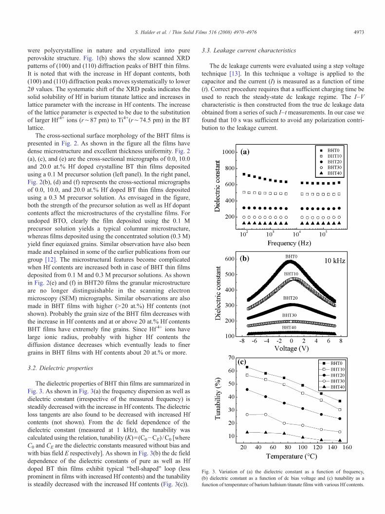
Fig. 3. Variation of (a) the dielectric constant as a function of frequency,(b) dielectric constant as a function of dc bias voltage and (c) tunability as afunction of temperature of barium hafnium titanate films with various Hf contents.
4973S. Halder et al. / Thin Solid Films 516 (2008) 4970–4976
were polycrystalline in nature and crystallized into pureperovskite structure. Fig. 1(b) shows the slow scanned XRDpatterns of (100) and (110) diffraction peaks of BHT thin films.It is noted that with the increase in Hf dopant contents, both(100) and (110) diffraction peaks moves systematically to lower2θ values. The systematic shift of the XRD peaks indicates thesolid solubility of Hf in barium titanate lattice and increases inlattice parameter with the increase in Hf contents. The increaseof the lattice parameter is expected to be due to the substitutionof larger Hf 4+ ions (r∼87 pm) to Ti4+(r∼74.5 pm) in the BTlattice.
The cross-sectional surface morphology of the BHT films ispresented in Fig. 2. As shown in the figure all the films havedense microstructure and excellent thickness uniformity. Fig. 2(a), (c), and (e) are the cross-sectional micrographs of 0.0, 10.0and 20.0 at.% Hf doped crystalline BT thin films depositedusing a 0.1 M precursor solution (left panel). In the right panel,Fig. 2(b), (d) and (f) represents the cross-sectional micrographsof 0.0, 10.0, and 20.0 at.% Hf doped BT thin films depositedusing a 0.3 M precursor solution. As envisaged in the figure,both the strength of the precursor solution as well as Hf dopantcontents affect the microstructures of the crystalline films. Forundoped BTO, clearly the film deposited using the 0.1 Mprecursor solution yields a typical columnar microstructure,whereas films deposited using the concentrated solution (0.3 M)yield finer equiaxed grains. Similar observation have also beenmade and explained in some of the earlier publications from ourgroup [12]. The microstructural features become complicatedwhen Hf contents are increased both in case of BHT thin filmsdeposited from 0.1 M and 0.3 M precursor solutions. As shownin Fig. 2(e) and (f) in BHT20 films the granular microstructureare no longer distinguishable in the scanning electronmicroscopy (SEM) micrographs. Similar observations are alsomade in BHT films with higher (N20 at.%) Hf contents (notshown). Probably the grain size of the BHT film decreases withthe increase in Hf contents and at or above 20 at.% Hf contentsBHT films have extremely fine grains. Since Hf 4+ ions havelarge ionic radius, probably with higher Hf contents thediffusion distance decreases which eventually leads to finergrains in BHT films with Hf contents about 20 at.% or more.
3.2. Dielectric properties
The dielectric properties of BHT thin films are summarized inFig. 3. As shown in Fig. 3(a) the frequency dispersion as well asdielectric constant (irrespective of the measured frequency) issteadily decreased with the increase in Hf contents. The dielectricloss tangents are also found to be decreased with increased Hfcontents (not shown). From the dc field dependence of thedielectric constant (measured at 1 kHz), the tunability wascalculated using the relation, tunability (K)=(C0−CE) /C0 [whereC0 and CE are the dielectric constants measured without bias andwith bias field E respectively]. As shown in Fig. 3(b) the dc fielddependence of the dielectric constants of pure as well as Hfdoped BT thin films exhibit typical “bell-shaped” loop (lessprominent in films with increased Hf contents) and the tunabilityis steadily decreased with the increased Hf contents (Fig. 3(c)).
3.3. Leakage current characteristics
The dc leakage currents were evaluated using a step voltagetechnique [13]. In this technique a voltage is applied to thecapacitor and the current (I) is measured as a function of time(t). Correct procedure requires that a sufficient charging time beused to reach the steady-state dc leakage regime. The I–Vcharacteristic is then constructed from the true dc leakage dataobtained from a series of such I–tmeasurements. In our case wefound that 10 s was sufficient to avoid any polarization contri-bution to the leakage current.

Fig. 4. Variation of the leakage current densities of BHT thin films as a functionof Hf contents.
4974 S. Halder et al. / Thin Solid Films 516 (2008) 4970–4976
The operative conduction mechanisms in insulating films canbe grouped into either electrode limiting or bulk limiting. In mostPt/perovskite/Pt systems the main current conduction mechan-isms are electrode limited, i.e. either Schottky emission orFowler–Nordheim tunnelling, or a combination of both [14]. Aseries of I–V measurements as a function of temperatures wasrecorded for the undoped as well as Hf substituted BT thin films.The field dependence of the leakage current characteristics ofthese films is shown in Fig. 4. As shown in the Figure, with theexception for BHT 20 films, in the high field region, the leakagecurrent is decreased systematically with the increase in Hfcontents. The leakage current behaviour of BHT20 films wererepeatedly observed at least in three samples of different batches.This unusual leakage current behaviour of BHT20 films is notclearly understood. Similar to Zr4+, probably Hf 4+ as a dopant inthe barium titanate lattice also reduces the cubic to tetragonaltransition temperature and simultaneously increases the ortho-
Fig. 5. Variation of the leakage current densities of BHT thin films as a functionof E1/2 measured at 150 °C. The symbols correspond to experimentally obtaineddata points whereas the solid lines correspond to linear fit according to Eq. (1)(see text).
rhombic to rhombohedral as well as rhombohedral to tetragonaltransition temperatures. Around 20 at.% Hf contents all thesethree phase transition temperatures merge at room temperatureand the increased leakage current densities at high electric field isthought to be related to the coexistence of perovskite phase ofdifferent crystalline symmetries. Further research is required tojustify this postulation. To test if Schottky emission is dominant,it is necessary to measure both the field as well as temperaturedependence of the leakage current. The current density (J ) onapplication of an electric field for Schottky mechanism behavesaccording to the following equation:
J ¼ AT2 expbE1=2 � qUb
kT
� �ð1Þ
where A is the effective Richardson constant, T is thetemperature, b ¼ ffiffiffiffiffiffiffiffiffiffiffiffiffiffiffiffiffiffiffiffiffi
q3=4kɛoɛrp
(q is the electron charge, ɛo isthe permittivity of vacuum and ɛr is the dielectric permittivity ofthe material measured at optical frequency), E is the appliedelectric field, Φb is the barrier height for conduction, and k is theBoltzmann constant.
According to the above relation, a plot of ln(J) vs. E1/2
would yield a straight line, as indeed has been observed in caseof undoped as well as Hf modified BTO thin films (Fig. 5).Additionally, when measured at constant electric field E, ac-cording to Eq. (1) the plot of ln(J /T 2) vs. 1000 /T also wouldyield a straight line. Fig. 6 shows the ln(J /T 2) vs. 1000 /T plotfor BHT thin films (symbols) and the linear fits (solid line).Calculating the values of β and knowing the value of the appliedfield E the barrier heights (qφb) for all the BHT films wereestimated from the slopes of these linear fits. Thus, the barrierheights are for BT, BHT10, BHT20, BHT30, BHT40 areestimated to be 1.05, 1.27, 1.29, 1.41 and 1.45 eV respectively.It can therefore be concluded that the systematic increase in thebarrier height with the increase of Hf substitution could beresponsible for the observed reduction of the leakage current asenvisaged in Fig. 4.
Fig. 6. Plot of J /T2 vs. 1000/T for BHT films with different Hf contents. Thelinear fit (solid lines) confirms the Schottky conduction mechanism.

Fig. 8. Variation of the estimated band gap with the Hf contents of BHT thinfilms.
Fig. 7. Transmission spectra of BHT0 thin film. As marked the figure also showsthe transmission spectrum of the quartz substrate and Tmax and Tmin envelops(see text).
4975S. Halder et al. / Thin Solid Films 516 (2008) 4970–4976
3.4. Optical properties
Transmission spectra of BHT0, BHT10, BHT20, BHT30, andBHT40 were recorded. A typical measured transmission spec-trum of a BHT0 thin film deposited on fused quartz substrate isshown in Fig. 7. The transmission spectrum of the blank quartzsubstrate has also been shown in the figure for comparison. Astrong optical absorption in the wavelength range of 320–380 nmis apparent and the appearance of the interference fringes indicateexcellent thickness uniformity of the annealed film which is alsosupported by the cross-sectional SEM micrograph presentedearlier. Note no such absorption edge is apparent in the fusedquartz substrate.
The optical band-gap energy (Eg) of the pure as well as Hfsubstituted BT films were estimated assuming a direct band-gaptransition upon the absorption of a photon energy hν [15]. Insuch case the absorption coefficient α is related to the band-gapenergy by the following equation
ahmð Þ2 ¼ C hm� Eg
� � ð2Þ
where α is the absorption coefficient, h is the Plank's constant,C is a constant and ν is the optical frequency.
As shown in Fig. 7 (Transmission spectra of only BHT0shown here), the variation (exponential) of the transmittance (T)with the wavelength is more pronounced near the absorptionedge. In this region, the absorption coefficient can be estimatedusing the following expression [16]
T ¼ K exp �adð Þ ð3Þwhere,
K ¼ 16nons n2 þ k2ð Þno þ nð Þ2þk2
h ins þ nð Þ2þk2
h i
n, no, ns are the refractive indices of the film, air and substraterespectively, k is the extinction coefficient and d is the thicknessof the film. Assuming, K is unity in the vicinity of the absorption
edge, and determining the thickness of the film accurately, fromthe measured T as a function of wavelength (λ), we couldestimate the value of α as a function of λ using Eq. (3). Thewavelength dispersion of α was used to plot (αhν)2 vs. hν whichwas eventually fitted with linear equation (Eq. (2)). Finally fromthe estimated slope and intercept of the linear fit, Eg wasestimated for undoped as well as Hf doped BTO thin films. Thus,for the direct band-gap transition, Eg for the BT film has beenestimated∼3.6 eVwhich matches well to the available publisheddata on BT and related materials [15]. Fig. 8 shows that there is asystematic increase of Eg with the increase of Hf dopant contents.For pure BaZrO3 the band gap is found to be around 5.0 eV,which is much wider than the pure BTO [17]. Recent studies onthe density of states and band calculations of pure ZrO2 and pureHfO2 indicate a slight increase in the band gap of HfO2 ascompared to ZrO2 [18]. Similarly, in our case the increase in bandgap with increased Hf substitution can be explained on the basisof larger crystal splitting of the Hf 5d states [19]. This increase inband gap could also affect the barrier heights of the metal-insulator contact.
An “envelope” method, as originally developed by Manifa-cier et al. [20] was used to estimate the refractive index and theextinction coefficient of undoped as well as Hf doped BT films.In the region where the transmittance was≥60 %, the followingequation was used to estimate the refractive index (n) as afunction of λ:
n ¼ M þ M 2 � n2on2s
� �1=2h i1=2ð4Þ
where,
M ¼ n2o þ n2s� �
=2þ 2nons Tmax � Tminð ÞTmaxTmin
This method considers the maxima and minima of thetransmission spectra as continuous functions of λ. Tmax(λ) andTmin(λ) are the envelopes connecting the peak (maximum) andthe minimum points of the curve T(λ) respectively (shown inFig. 7 for BHT0, the graphs for the other compositions are notshown here). Eq. (4) can be used to calculate n(λ) and then by

Fig. 9. Variation of (a) the refractive index and (b) the extinction coefficient as afunction of the wavelength for the BHT thin films with different Hf contents.
4976 S. Halder et al. / Thin Solid Films 516 (2008) 4970–4976
assuming Tmax(λ) = (−αd), and a ¼ 4kkk k can be calculated [21].
The estimated values of n and k as a function of the wavelength(λ) are shown in Fig. 9 (a) and (b), respectively. From Fig. 9(a) itis observed that the refractive indices are systematically reducedwith the increase of Hf doping contents. No apparent correlationis observed between the estimated k (extinction coefficient) andthe amount of Hf substitution.
4. Conclusion
In conclusion, thin films of different composition weredeposited on platinised silicon substrates and quartz substrates.The dielectric properties and tunability were found to decrease
with increasing hafnium concentrations. Leakage measure-ments reveal Schottky type conduction behaviour with increaseof the Schottky barrier height with films containing higherhafnium contents. The band gaps of these films were calculatedand found to increase systematically with increase in hafniumconcentration. Refractive index and extinction coefficient of thefilms were calculated by the envelope method. Therefore thereduction in leakage could be due to the effect of an increase inSchottky barrier height and a simultaneous increase in the bandgap of the material.
Acknowledgment
One of the authors (S.B. Majumder) gratefully acknowledgesthe support rendered by Alexander von Humboldt foundationthrough Humboldt research fellowship.
References
[1] D.E. Kotecki, IBM J. Res. Develop. 43 (1999) 367.[2] A. Dixit, S.B. Majumder, R.S. Katiyar, A.S. Bhalla, J. Mater. Sci. 41 (2006)
87.[3] F.M. Pontes, J. Appl. Phys. 96 (2004) 4386.[4] S. Halder, T. Schneller, U. Boettger, R. Waser, Appl. Phys. A 81 (2005) 25.[5] A. Dixit, S.B. Majumder, R.S. Katiyar, A.S. Bhalla, Ferroelectr. Lett. Sect.
32 (2005) 131.[6] F.D. Morrison, D.C. Sinclair, A.R. West, J. Appl. Phys. 86 (1999) 6355.[7] M. Khan, H. Kim, T. Kusawake, H. Kudo, K. Ohshima, H. Uwe, J. Appl.
Phys. 86 (1999) 2307.[8] A. Dixit, S.B. Majumder, R.S. Katiyar, A.S. Bhalla, Appl. Phys. Lett.
82 (2003) 2679.[9] E.G. Fesenko, O.I. Prokopolo, Sov. Phys. Crystallogr. 6 (1961) 373.[10] W.H. Payne, V.J. Tennery, J. Am. Ceram. Soc. 48 (1965) 413.[11] R.W. Schwartz, T. Schneller, R. Waser, C.R. Chim. 7 (2004) 433.[12] S. Hoffmann, R. Waser, J. Eur. Ceram. Soc. 19 (1999) 1339.[13] G.W. Dietz, M. Schumacher, R. Waser, S.K. Streiffer, C. Basceri, A.I.
Kingon, J. Appl. Phys. 82 (1997) 2359.[14] J.J. O'Dwyer, The Theory of Electrical Conduction and Breakdown in
Solid Dielectrics, Clarendon, Oxford, 1973.[15] M.L. Kamalasanan, S. Chandra, P.C. Joshi, A. Mansingh, Appl. Phys. Lett.
59 (1991) 3547.[16] R. Thomas, D.C. Dube, Jpn. J. Appl. Phys. 39 (2000) 1771.[17] S.N. Prosandayev, Y.Y. Tarasevich, N.M. Teslenko, Ferroelectrics 131 (1992)
137.[18] P.W. Peacock, J. Robertson, J. Appl. Phys. 92 (2002) 4712.[19] A.A. Demkov, Phys. Status Solidi B 226 (2001) 57.[20] J.C. Manifacier, J. Gasiot, J.P. Fillard, J. Phys. E. 9 (1976) 1002.[21] A.A. Dakhel, J. Opt. A-Pure Appl. Opt. 3 (2001) 452.


![Barium titanate flakes based composites for microwave ... 22 07.pdf189 Processing and Application of Ceramics 7 [4] (2013) 189–193 Barium titanate flakes based composites for microwave](https://static.fdocuments.net/doc/165x107/5af12cfc7f8b9a8b4c8e7041/barium-titanate-flakes-based-composites-for-microwave-22-07pdf189-processing.jpg)