ELECTRICAL AND MECHANICAL VEHICLE G 202 ENGINEERING ...
61
UNCONTROLLED IF PRINTED ELECTRICAL AND MECHANICAL ENGINEERING INSTRUCTIONS VEHICLE G 202 Issue 3, Feb 11 1 TRUCK, CARGO, LIGHT AND TRUCK, CARGO, LIGHT, WINCH, MC2 – LAND ROVER 110 6X6 TECHNICAL DESCRIPTION This instruction is authorised for use by command of the Chief of Army. It provides direction, mandatory controls and procedures for the operation, maintenance and support of equipment. Personnel are to carry out any action required by this instruction in accordance with EMEI General A 001. TABLE OF CONTENTS Page No Page No INTRODUCTION ................................................................... 3 Associated Publications .................................................... 3 Maintenance Supply Item (MSI) Identification................... 4 GENERAL INFORMATION ................................................... 4 Engine ............................................................................... 4 Fuel System ...................................................................... 4 Clutch ................................................................................ 4 Transmission ..................................................................... 4 Rear Axles......................................................................... 4 Front Axle .......................................................................... 4 Brakes ............................................................................... 4 Suspension ....................................................................... 5 Steering ............................................................................. 5 Electrical............................................................................ 5 Frame ................................................................................ 5 Body .................................................................................. 5 Wheels .............................................................................. 6 Winch ................................................................................ 6 DETAILED DESCRIPTION.................................................... 6 Engine ............................................................................... 6 Lubrication System............................................................ 8 Cooling System ................................................................. 9 Air Cleaner ...................................................................... 11 Fuel System .................................................................... 12 Fuel Metering .................................................................. 15 Fuel Injectors................................................................... 18 Injection Pump Governor ................................................ 18 Automatic Timer .............................................................. 25 Exhaust System .............................................................. 28 Clutch.............................................................................. 28 Transmission................................................................... 29 Transfer Case ................................................................. 31 Power Take-off (PTO) ..................................................... 32 Torque Limiter ................................................................. 33 Propeller Shafts .............................................................. 34 Rear Axles ...................................................................... 34 Front Axle........................................................................ 35 Brakes ............................................................................. 36 Rear Disc Brakes ............................................................ 41 Parking Brake ................................................................. 42 Front Suspension............................................................ 44 Rear Suspension ............................................................ 44 Steering........................................................................... 45 Electrical System ............................................................ 48 Starter Motor ................................................................... 49 Alternator ........................................................................ 51 Lighting ........................................................................... 52 Wiring Harnesses............................................................ 54 Towing Pintle .................................................................. 55 Cab ................................................................................. 56 Bonnet............................................................................. 56 Mudguards ...................................................................... 57 Cabin Doors .................................................................... 58 Rear Body ....................................................................... 59 Winch .............................................................................. 60 LIST OF FIGURES Page No Page No Figure 1 Frame Assembly ....................................................... 5 Figure 2 Tyre, Tube and Rim .................................................. 6 Figure 3 Isuzu Engine 4BDT1, Right-hand Side ..................... 7 Figure 4 Isuzu Engine 4BDT1, Left-hand Side........................ 7 Figure 5 Oil Pump – Exploded View ....................................... 8 Figure 6 Thermostat Operation ............................................... 9 Figure 7 Water Pump Assembly ........................................... 10 Figure 8 Cooling System – Coolant Flow.............................. 10 Figure 9 Air Cleaner Assembly – Exploded View.................. 11 Figure 10 Air Cleaner Service Indicator ................................ 12 Figure 11 Fuel System .......................................................... 12 Figure 12 Fuel Sedimenter ................................................... 13 Figure 13 Intake Stroke......................................................... 13 Figure 14 Discharge Stroke .................................................. 14 Figure 15 Pump Pressure Regulating................................... 14 Figure 16 Main Fuel Filter ..................................................... 14 Figure 17 Plunger ................................................................. 15 Figure 18 Barrel – Sectional View......................................... 15 Figure 19 Plunger Rotating Mechanism................................ 16 Figure 20 Plunger Drive Assembly ....................................... 16 Figure 21 Housing and Delivery Valve Location ................... 17 Figure 22 Phases (Strokes) of the Plunger ........................... 17
Transcript of ELECTRICAL AND MECHANICAL VEHICLE G 202 ENGINEERING ...

UN
CO
NTR
OLL
ED IF
PR
INTE
D
ELECTRICAL AND MECHANICAL ENGINEERING INSTRUCTIONS
VEHICLE G 202Issue 3, Feb 11
1
TRUCK, CARGO, LIGHT AND TRUCK, CARGO, LIGHT, WINCH, MC2 – LAND ROVER 110 6X6
TECHNICAL DESCRIPTION
This instruction is authorised for use by command of the Chief of Army. It provides direction, mandatory controls and procedures for the operation, maintenance and support of equipment. Personnel are to carry out any action required by this instruction in accordance with EMEI General A 001.
TABLE OF CONTENTS
Page No Page No INTRODUCTION ...................................................................3
Associated Publications ....................................................3 Maintenance Supply Item (MSI) Identification...................4
GENERAL INFORMATION ...................................................4 Engine ...............................................................................4 Fuel System ......................................................................4 Clutch ................................................................................4 Transmission.....................................................................4 Rear Axles.........................................................................4 Front Axle..........................................................................4 Brakes ...............................................................................4 Suspension .......................................................................5 Steering.............................................................................5 Electrical............................................................................5 Frame................................................................................5 Body ..................................................................................5 Wheels ..............................................................................6 Winch ................................................................................6
DETAILED DESCRIPTION....................................................6 Engine ...............................................................................6 Lubrication System............................................................8 Cooling System .................................................................9 Air Cleaner ......................................................................11 Fuel System ....................................................................12 Fuel Metering ..................................................................15 Fuel Injectors...................................................................18 Injection Pump Governor ................................................18 Automatic Timer ..............................................................25
Exhaust System.............................................................. 28 Clutch.............................................................................. 28 Transmission................................................................... 29 Transfer Case ................................................................. 31 Power Take-off (PTO)..................................................... 32 Torque Limiter................................................................. 33 Propeller Shafts .............................................................. 34 Rear Axles ...................................................................... 34 Front Axle........................................................................ 35 Brakes............................................................................. 36 Rear Disc Brakes............................................................ 41 Parking Brake ................................................................. 42 Front Suspension............................................................ 44 Rear Suspension ............................................................ 44 Steering........................................................................... 45 Electrical System ............................................................ 48 Starter Motor ................................................................... 49 Alternator ........................................................................ 51 Lighting ........................................................................... 52 Wiring Harnesses............................................................ 54 Towing Pintle .................................................................. 55 Cab ................................................................................. 56 Bonnet............................................................................. 56 Mudguards ...................................................................... 57 Cabin Doors .................................................................... 58 Rear Body ....................................................................... 59 Winch.............................................................................. 60
LIST OF FIGURES
Page No Page No Figure 1 Frame Assembly .......................................................5 Figure 2 Tyre, Tube and Rim ..................................................6 Figure 3 Isuzu Engine 4BDT1, Right-hand Side .....................7 Figure 4 Isuzu Engine 4BDT1, Left-hand Side........................7 Figure 5 Oil Pump – Exploded View .......................................8 Figure 6 Thermostat Operation ...............................................9 Figure 7 Water Pump Assembly ...........................................10 Figure 8 Cooling System – Coolant Flow..............................10 Figure 9 Air Cleaner Assembly – Exploded View..................11 Figure 10 Air Cleaner Service Indicator ................................12 Figure 11 Fuel System ..........................................................12
Figure 12 Fuel Sedimenter ................................................... 13 Figure 13 Intake Stroke......................................................... 13 Figure 14 Discharge Stroke .................................................. 14 Figure 15 Pump Pressure Regulating................................... 14 Figure 16 Main Fuel Filter ..................................................... 14 Figure 17 Plunger ................................................................. 15 Figure 18 Barrel – Sectional View......................................... 15 Figure 19 Plunger Rotating Mechanism................................ 16 Figure 20 Plunger Drive Assembly ....................................... 16 Figure 21 Housing and Delivery Valve Location................... 17 Figure 22 Phases (Strokes) of the Plunger........................... 17

UN
CO
NTR
OLL
ED IF
PR
INTE
D
VEHICLE G 202 Issue 3, Feb 11
ELECTRICAL AND MECHANICAL ENGINEERING INSTRUCTIONS
2
Figure 23 Fuel Injector Assembly ......................................... 18 Figure 24 Governor Assembly .............................................. 19 Figure 25 Flyweights Closed................................................. 19 Figure 26 Flyweights Open ................................................... 20 Figure 27 Tension Lever and Governor Shaft....................... 20 Figure 28 Governor Springs and Idling Spring Locations ..... 20 Figure 29 Guide Lever and Cancel Spring (1) Location........ 21 Figure 30 Connecting Link and Start Spring Location .......... 21 Figure 31 Control Assembly – Exploded View...................... 21 Figure 32 Torque Cam Location ........................................... 22 Figure 33 Full-load Setting Lever and Sensor Lever
Locations..................................................................... 22 Figure 34 Control Lever Assembly Operation....................... 22 Figure 35 Engine Start Position ............................................ 23 Figure 36 Returning to the Idle Position................................ 23 Figure 37 Governing Idle Speed ........................................... 24 Figure 38 Full-load Operation ............................................... 24 Figure 39 Maximum Speed Control ...................................... 25 Figure 40 Automatic Timer – Exploded View........................ 26 Figure 41 Automatic Timer – Static Position......................... 26 Figure 42 Flyweights in Timing Advance Position ................ 27 Figure 43 Exhaust System.................................................... 28 Figure 44 Clutch Assembly – Sectional View ....................... 29 Figure 45 Transmission Assembly – Sectional View ............ 30 Figure 46 Drive Transmitted Through the Gears .................. 31 Figure 47 Transfer Case and Differential – Sectional
View ............................................................................ 32 Figure 48 PTO Location........................................................ 32 Figure 49 PTO and Torque Limiter Assembly....................... 33 Figure 50 Torque Limiter and Output Shaft – Exploded
View ............................................................................ 33 Figure 51 Front, Intermediate and Rear Propeller Shafts ..... 34 Figure 52 Intermediate and Rear Axle Assemblies............... 35 Figure 53 Front Axle Assembly............................................. 35 Figure 54 Steerable Drive-end – Sectional View .................. 36 Figure 55 Dual Master Cylinder – Exploded View ................ 36 Figure 56 Pressure Differential Switch – Location ................ 37 Figure 57 Hydraulic Circuit – Normal Condition.................... 38 Figure 58 Hydraulic Circuit – Front Brake Failure................. 38 Figure 59 Hydraulic Circuit – Rear Brake Failure ................. 38 Figure 60 Brake Servo Vacuum Chamber – Exploded
View ............................................................................ 39
Figure 61 Servo Diaphragms Stationary – Engine Running, Brakes Released ......................................... 40
Figure 62 Servo Chamber Operating – Brakes Applied ....... 40 Figure 63 Front Disc Brake Assembly – Exploded View ...... 41 Figure 64 Rear Disc Brake Assembly – Exploded View....... 42 Figure 65 Parking Brake Expander Assembly –
Exploded View ............................................................ 42 Figure 66 Parking Brake Expander Operation...................... 43 Figure 67 Parking Brake Assembly – Exploded View........... 43 Figure 68 Front Suspension – Left-hand Side ...................... 44 Figure 69 Rear Suspension .................................................. 45 Figure 70 Steering Wheel, Column and Upper Shaft
Assembly .................................................................... 46 Figure 71 Steering Shaft (Lower Section) and Coupling
– Exploded View ......................................................... 46 Figure 72 Steering Box Assembly – Exploded View............. 47 Figure 73 Drop Arm, Steering Linkages and Steering
Damper ....................................................................... 48 Figure 74 Engine Electrical Circuit........................................ 49 Figure 75 Ignition Switch OFF .............................................. 49 Figure 76 Ignition Switch in START...................................... 50 Figure 77 Starter Motor – Exploded View............................. 50 Figure 78 Rotor and Stator Assembly................................... 51 Figure 79 Rotor and Magnetic Field ..................................... 51 Figure 80 Alternator and Vacuum Pump – Exploded
View ............................................................................ 52 Figure 81 Lighting Control Switch Location .......................... 52 Figure 82 Front Wiring Harness............................................ 54 Figure 83 Rear Wiring Harness ............................................ 54 Figure 84 Cabin Wiring ......................................................... 55 Figure 85 Towing Pintle – Exploded View ............................ 55 Figure 86 Cab Assembly ...................................................... 56 Figure 87 Bonnet and De-ditching Tool Holders –
Exploded View ............................................................ 56 Figure 88 Left-hand Front Outer Mudguard – Exploded
View ............................................................................ 57 Figure 89 Left-hand Front Inner Mudguard and Wheel
Arch Trim – Exploded View......................................... 58 Figure 90 Front Door – Exploded View................................. 58 Figure 91 Rear Body – Exploded View................................. 59 Figure 92 Tool Box ............................................................... 60 Figure 93 Winch Drive Line .................................................. 60 Figure 94 Fairlead Assembly ................................................ 61
LIST OF TABLES
Page No Table 1 Location of Identification Numbers on MSI ................ 4 Table 2 Globe Wattage ......................................................... 53

UN
CO
NTR
OLL
ED IF
PR
INTE
D
ELECTRICAL AND MECHANICAL ENGINEERING INSTRUCTIONS
VEHICLE G 202Issue 3, Feb 11
3
INTRODUCTION
1. This EMEI contains the technical description of the Truck, Cargo, Light and the Truck, Cargo, Light with Winch. The body, chassis and engine have common features with other variants, therefore, it is possible to transfer the operating roles of the vehicle by transferring bodies from chassis to chassis (refer to EMEI Vehicle G 204-2). Each chassis is fitted with the necessary brackets to allow for the fitment of a 28 V electrical system and there is provision for the fitment of electrical connectors in the rear of the cab. Wiring is also available in the dashboard for additional instruments. All relevant weights, dimensions and performance figures are detailed in the Data Summary EMEI Vehicle G 200.
Associated Publications
2. Reference may be necessary to the latest issue of the following documents:
a. Defence Road Traffic Instructions (DRTI);
b. Complete Equipment Schedules (CES):
(1) SCES 012044...................................................................................... Truck, Cargo, Light, MC2;
(2) SCES 012046..........................................................................Truck, Cargo, Light, Winch, MC2;
c. Block Scale 2406/31 – Special Tools for RAEME – B Vehicles – Truck, Utility and Truck, Light, MC2 (Land Rover Model 110);
d. EMEI Vehicle A 029-3 – Vehicles – General, Servicing of B Vehicles, Trailers, All Terrain Vehicles (ATV) and Motorcycles – General Instruction;
e. EMEI Vehicle A 291-5 – Tyres and Tubes, General Service B Vehicles Tyre Guide – Operator Instructions;
f. EMEI Vehicle G 200 – Truck, Cargo, Light and Truck, Cargo, Light, Winch, MC2 – Land Rover 110 6 x 6 – Data Summary;
g. EMEI Vehicle G 203 – Truck, Cargo, Light and Truck, Cargo, Light, Winch, MC2 – Land Rover 110 6 x 6 – Light Grade Repair;
h. EMEI Vehicle G 204-1 – Truck, Cargo, Light and Truck, Cargo, Light, Winch, MC2 – Land Rover 110 6 x 6 – Medium Grade Repair;
i. EMEI Vehicle G 204-2 – Truck, Cargo, Light and Truck, Cargo, Light, Winch, MC2 – Land Rover 110 6 x 6 – Heavy Grade Repair;
j. EMEI Vehicle G 209 – Truck, Cargo, Light and Truck, Cargo, Light, Winch, MC2 – Land Rover 110 6 x 6 – Servicing Instruction;
k. RPS 02185 (Base Scale); and
l. RPS 02186 (Supplement W/Winch).
All industrial safety, work practices, equipment operating and maintenance instructions pertaining to this EMEI are to be adhered to.
The handling, storage and use of chemical substances are to be in accordance with MOHS, MSDS and EMEI Workshop E series requirements.
UN
CO
NTR
OLL
ED IF
PR
INTE
D
VEHICLE G 202 Issue 3, Feb 11
ELECTRICAL AND MECHANICAL ENGINEERING INSTRUCTIONS
4
Maintenance Supply Item (MSI) Identification
3. The locations of identification numbers on MSI of the vehicle are described in Table 1.
Table 1 Location of Identification Numbers on MSI
Serial Identification Number Location
1 Chassis Number Right-hand side of the chassis, forward of the spring mounting turret
2 Chassis Nameplate Left-hand seat box, in the cab
3 Engine Number Left-hand side of the engine block
4 Injection Pump Identification Side of the pump
5 Transmission and Transfer Case Rear of the transfer case
GENERAL INFORMATION
Engine
4. An Isuzu 4BD1 TRB-G overhead valve, water-cooled, four-cycle, four-cylinder in-line, turbocharged diesel engine powers the vehicle. The engine utilises an open combustion chamber design with direct fuel injection. The cylinders are numbered from the front to the rear of the engine. The crankshaft rotates in a clockwise direction when viewed from the front of the vehicle.
Fuel System
5. The fuel system is comprised of two 62 L fuel tanks, low-pressure fuel pipes/hoses, a motor-driven fuel change-over valve, two chassis mounted sedimenters, a fuel transfer (supply) pump, a main fuel filter, a fuel injection pump, high-pressure fuel pipes and injectors.
Clutch
6. The pressure plate assembly utilises a single dry plate and diaphragm spring. The clutch (driven) plate has a diameter of 274.1–275.6 mm with the lining material riveted to both sides. The clutch pedal controls the operation of the clutch via a hydraulic system, clutch lever and release bearing.
Transmission
7. The transmission is a LT95A four-speed with helical constant mesh gears. All forward gears are equipped with synchromesh.
8. The transfer case, fitted to the transmission, provides high and low gear ratios for on and off road driving. The low ratio is for cross-country (off road) driving, while the high ratio is for sealed or formed roads. A differential within the transfer case prevents wind-up between the front and rear axles. For extreme driving conditions, where traction is difficult, the differential can be locked by operating a switch, located on the dashboard, to give the vehicle positive all-wheel drive.
Rear Axles
9. Two axle assemblies, each with a load rating of 1 950 kg, are used at the rear of the vehicle. Each assembly houses a Salisbury 8HA differential (with a reduction ratio of 4.7:1), two full floating axles (half shafts) and two hubs.
Front Axle
10. The steerable front drive axle has a load rating of 1 650 kg and a bevel type differential with a ratio of 4.7:1, to transmit drive, via enclosed constant velocity joints, to the front wheels.
Brakes
11. The brake system is hydraulically operated and uses disc brakes to the front and rear wheels. A pedal actuated tandem master cylinder with pressure differential and servo (vacuum) assistance applies the pressure required to operate the brakes. Brake hydraulic fluid is stored in a reservoir on top of the master cylinder.

UN
CO
NTR
OLL
ED IF
PR
INTE
D
ELECTRICAL AND MECHANICAL ENGINEERING INSTRUCTIONS
VEHICLE G 202Issue 3, Feb 11
5
Suspension
12. Long travel single-rate coil springs are utilised on the front axle, while four semi-elliptic leaf springs are utilised on the intermediate and rear axles. The ends of the leaf springs between the axles overlap each other and are mounted on load-sharing rocker beams. This allows the springs to articulate in accordance with the movement of the axles. Double acting shock absorbers are fitted on the front and rear axles to dampen the spring rebound, while chassis mounted pads and cables control the bump and rebound of the axles.
Steering
13. A power-assisted, variable-ratio, worm and roller-type steering box is used for the vehicle steering. The steering box (mounted on the chassis rail) is connected to the front-wheel steering knuckles by means of a drag link (cross rod) and a track rod. A steering damper, connected between the drag link and the chassis, absorbs road shock feedback transmitted by the front wheels. A three-piece steering column connects the steering wheel to the steering box for driver control. A gear-driven pump (mounted on and driven by the engine) pumps fluid under high pressure to assist with the rotation of the sector shaft. The high-pressure fluid acts against and moves a rack, which in turn pushes against a gear on the sector shaft rotating the sector shaft in accordance with the direction that the steering wheel is turned.
Electrical
14. The vehicle utilises a 12 V electrical system for engine starting and vehicle lighting. A starter motor with gear reduction is used for starting and an alternator is used for battery recharge purposes. The battery is stored in the engine compartment.
Frame
15. The frame consists of two parallel steel box-section chassis rails held in position by five cross members. The vehicle’s major assemblies, e.g. body, engine, transmission and drive axles, are mounted on or connected to the frame. The frame is hot-dip galvanised to prevent the formation of rust on the chassis rails and/or the cross members. The cross member situated below the transmission can be removed to facilitate transmission removal (refer to Figure 1).
Figure 1 Frame Assembly
Body
16. The vehicle’s body consists of three box sections: an engine compartment, a two-door cab, and a utility (open box) type rear section. A canvas canopy can be fitted over the rear section of the vehicle effectively closing off the rear section to the elements.

UN
CO
NTR
OLL
ED IF
PR
INTE
D
VEHICLE G 202 Issue 3, Feb 11
ELECTRICAL AND MECHANICAL ENGINEERING INSTRUCTIONS
6
Wheels
17. The wheel assembly (refer to Figure 2) consists of a ventilated disc wheel rim, tyre and tube. Refer to EMEI Vehicle A 291-5 for the tyre type and the tyre pressure details.
Figure 2 Tyre, Tube and Rim
Winch
18. Where fitted, a Thomas T9000M mechanical winch is used. The winch drive comes from the transmission via a power take-off unit, which is transmitted to the front-mounted winch via a propeller shaft and torque limiter. The winch uses a 45 metre long by 11 mm diameter wire rope with a 2-metre chain and hook connected to the free end of the winch rope by a hammerlock.
DETAILED DESCRIPTION
Engine
19. Construction. The cylinder block and crankcase are cast in one piece. The engine block carries the camshaft bearings, the crankshaft main bearings and removable dry type cylinder liners. A water jacket incorporated within the engine block allows coolant to circulate around each cylinder to assist in keeping the engine at a constant operating temperature.
20. The cylinder head, which is detachable from the engine block, provides both the air inlet and exhaust gas ports and a means of sealing each cylinder. A gasket provides a gas/water tight seal when the cylinder head is bolted to the engine block. The alloy valve seats are pressed into place in the cylinder head and are, along with the valves, cooled when coolant flows up from the engine block and circulates through the passages in the head. The coolant also maintains the cylinder head at a constant temperature.
21. The crankshaft is drop-forged heat-treated steel, counter-weighted, machine ground to close limits and balanced. The shaft is mounted in five replaceable, precision shell-type bearings. Crankshaft end thrust is taken up on the number three bearing.
22. The camshaft, machined from a solid drop forging, is mounted in three replaceable bearings located in the engine block. A gear, integral with the camshaft, provides drive to the oil pump.
23. The cam ground pistons are made of aluminium alloy and fitted with two compression rings and one oil control ring. The crown of the piston is recessed for the combustion chamber and machined to allow the inlet and exhaust valves to open as they protrude below the surface of the cylinder head.
24. The flywheel is machined from a solid drop forging and bolted to the rear flange on the crankshaft. The ring-gear is heat shrunk onto the flywheel.
25. The camshaft drives a gear type oil pump. Oil drawn from the oil pan (sump) is pumped under pressure to the engine lubricating system via an oil pressure relief valve and a filter. The pressure relief valve prevents the oil pressure from exceeding the required pressure. A removable oil cooler is installed in the engine block and utilises the engine coolant to maintain the engine oil at a constant operating temperature.
26. Figures 3 and 4 illustrate the right- and left-hand views of the engine and show the location of the various components.

UN
CO
NTR
OLL
ED IF
PR
INTE
D
ELECTRICAL AND MECHANICAL ENGINEERING INSTRUCTIONS
VEHICLE G 202Issue 3, Feb 11
7
Figure 3 Isuzu Engine 4BDT1, Right-hand Side
Figure 4 Isuzu Engine 4BDT1, Left-hand Side

UN
CO
NTR
OLL
ED IF
PR
INTE
D
VEHICLE G 202 Issue 3, Feb 11
ELECTRICAL AND MECHANICAL ENGINEERING INSTRUCTIONS
8
Lubrication System
27. The purpose of the lubrication system is to deliver oil under pressure to the various engine components that require lubrication.
28. The oil pan is constructed from pressed steel and is bolted to the bottom of the engine block. It not only protects the lower internal components of the engine, e.g. oil pump, crankshaft, con rods, etc, but is also the storage reservoir for approximately 7.5 litres of engine oil. A dipstick, located on the left-hand side of the engine, enables the engine oil to be monitored for both quality and quantity.
29. The oil pump, located inside the oil pan, is a gear type, i.e. a pair of meshing gears inside a closed housing, and is mounted on the engine block. One gear is attached to the pump drive shaft, which is driven by a gear on the camshaft, while the second gear is driven by the first (refer to Figure 5). The oil pump is a self-priming type, i.e. when the pump gears are rotating, a low-pressure area is created in the pump housing causing atmospheric pressure to force oil through the oil strainer and inlet tube into the pump housing. The meshing of the pump gears displaces the oil and forces the oil from the pump. A pressure-relief valve in the pump housing limits the maximum pump outlet pressure to 686 kPa (100 psi). Surplus pump output is bypassed to the oil pan.
30. The pressure regulating (relief) valve in the lubrication system operates in the same manner as the oil pump relief valve. The regulating valve maintains a constant pressure in the lubrication system by means of a ball and a spring. When oil pressure in the lubricating system exceeds the desired pressure, the pressurised oil acts on the ball forcing it to compress the spring and open a gallery, which allows oil to drain back to the oil pan and relieve the pressure within the system. The regulating valve limits the oil pressure within the oil galleries to 441 kPa (64 psi).
31. The oil filter, mounted vertically on the right-hand side of the engine towards the rear, receives the oil from the oil pump and filters out the finer contaminants, which have passed through the oil pump inlet tube strainer. The oil flows through the oil adaptor into the filter housing and passes through the filter element, outside-to-inside, trapping the contaminants on the outside of the element. The clean oil then flows upward through the oil adaptor into the oil galleries. If the filter becomes blocked, a bypass relief valve, located in the oil adaptor, allows oil to bypass the filter restricting the oil flow.
Figure 5 Oil Pump – Exploded View

UN
CO
NTR
OLL
ED IF
PR
INTE
D
ELECTRICAL AND MECHANICAL ENGINEERING INSTRUCTIONS
VEHICLE G 202Issue 3, Feb 11
9
32. An oil cooler is installed in the lubrication system to prevent the oil from overheating, which causes chemical degradation of the oil and the loss of lubricating qualities. A relief valve, located in the oil cooler housing, allows oil to bypass the cooler should it become blocked. The oil cooler is installed in the water jacket, behind a cover on the right-hand side of the engine, where engine coolant can flow over the oil cooler, dissipating the heat and cooling the oil.
33. Oil galleries direct the flow of oil to the various components requiring lubrication, e.g. crankshaft bearings mains and big ends, camshaft bearings, rocker arm shaft and the fuel injection pump. Four outlet nozzles connected to the main oil gallery direct jets of oil to the underside of the piston crowns to aid piston cooling. The jets of oil also provide additional lubrication to the gudgeon (piston) pins and piston rings by means of splash lubrication. Other components are splash lubricated by the oil run-off from the pressure-lubricated parts.
Cooling System
34. The cooling system consists of the following:
a. coolant, which contains Nalcool corrosion inhibitor in water at a ratio of 1:12;
b. water jackets and passages in the engine block and cylinder head;
c. a belt-driven centrifugal water pump;
d. a thermostat;
e. a chassis mounted radiator, which is connected to the water pump inlet and the thermostat housing outlet by flexible rubber hoses; and
f. an expansion tank, which is equipped with a removable pressure cap and connected to the radiator by means of a rubber hose.
35. Although the primary function of the cooling system is to maintain the engine at a constant operating temperature, it also assists the engine to quickly warm up to the normal operating temperature. When the engine/coolant is cold, the thermostat is closed, restricting coolant flow. The water pump circulates the coolant only through the engine block and cylinder head, via the bypass hose. When a coolant temperature of 82°C is reached, the thermostat opens, allowing the coolant to flow from the thermostat housing and circulate through the radiator, where it is cooled before being drawn back into the engine.
36. The thermostat is a wax pellet, disposable type, designed to open when a coolant temperature of 82°C is reached. At lower temperatures, spring pressure keeps the thermostat closed and the bypass valve at the bottom of the thermostat opens. This allows coolant to circulate from the water pump through the engine and back to the water pump via the bypass hose. As the desired temperature is reached, the wax pellet within the thermostat melts and expands. This exerts pressure on the plunger, which overcomes the spring pressure, opening the thermostat and closing the bypass valve (refer to Figure 6). Heated coolant now flows from the engine to the radiator.
Figure 6 Thermostat Operation

UN
CO
NTR
OLL
ED IF
PR
INTE
D
VEHICLE G 202 Issue 3, Feb 11
ELECTRICAL AND MECHANICAL ENGINEERING INSTRUCTIONS
10
37. The radiator is a cross flow type, i.e. the tanks are located on the sides of the radiator and the flutes run horizontally across the core. Each flute contains metal fins over its entire length, which by convection are heated to the temperature of the coolant. Airflow, induced by the forward motion of the vehicle and by the cooling system fan, passes through the radiator core dissipating heat from the fins, thereby reducing the temperature of the flutes and the coolant flowing through the flutes.
38. The expansion tank allows the heated coolant, which has expanded, to flow from the radiator into the tank via a rubber hose. The removable pressure cap, fitted to the expansion tank, maintains the cooling system under pressure, which effectively raises the boiling point of the coolant, enabling the engine to operate at high temperatures. The pressure cap is equipped with a pressure relief valve, rated at 103 kPa (15 psi), and a vacuum valve. Should the pressure exceed the specified limit, the pressure relief valve opens, allowing internal pressures to be vented to the atmosphere. After the engine is shut down, the coolant and the air within the cooling system contract, creating a partial vacuum. In this case, the vacuum valve opens, allowing outside air to enter. Damage to the radiator and/or hoses may result should either the pressure relief valve or the vacuum valve fail to function properly.
39. The water pump shown in Figure 7 is a belt-driven, mechanical, centrifugal type pump bolted to the front of the engine block. Drive for the water pump comes from the crankshaft pulley, via a V-belt, to the pulley attached to the water pump shaft. The coolant is drawn in through the inlet port, forced out through the port in the cover plate and into the engine block water jacket. An eight-blade fan, attached to the water pump impeller shaft, assists with engine cooling by drawing air through the radiator core, cooling the contents of the radiator, and circulating air over the engine extremities.
Figure 7 Water Pump Assembly
40. When the coolant in the cooling system reaches 82°C, the thermostat begins to open, permitting coolant to flow through the thermostat housing to the radiator, via the radiator hose. The coolant flows from the left-hand radiator tank through the flutes in the radiator core (where it is cooled) to the right-hand tank. The coolant then is drawn from the right-hand tank through the lower radiator hose to the water pump, where it is pumped into the engine block water jacket. The coolant circulates around the cylinders dissipating the heat from the cylinder walls. It then flows into the cylinder head where it circulates around the inlet and exhaust ports, cooling the valve seats and valves before flowing through the thermostat housing to the radiator to repeat the cooling cycle. An outlet incorporated on the water pump provides coolant to the turbocharger (refer to Figure 8) for cooling the bearing housing. The coolant then flows via piping to the thermostat housing.
Figure 8 Cooling System – Coolant Flow

UN
CO
NTR
OLL
ED IF
PR
INTE
D
ELECTRICAL AND MECHANICAL ENGINEERING INSTRUCTIONS
VEHICLE G 202Issue 3, Feb 11
11
Air Cleaner
41. The air cleaner is utilised for the filtering of the air used in the engine’s combustion process (refer to Figure 9). The air cleaner assembly is mounted on the rear of the engine and held in position by two metal bands. Incorporated within the air cleaner assembly’s housing are the primary element and the safety element. The primary or main element is a dry-type paper element with a perforated metal surround and a plastic fin assembly fitted to one end. When the element is installed, the fin assembly is positioned towards the air inlet port in the housing. As air is drawn into the housing, via the air inlet hose, it passes between the fins, which induce a cyclonic twist to the air as it flows through. This action tends to cause the larger or heavier dust particles to be thrown outward, eventually falling to the bottom of the housing. The air then passes through the primary filter, which extracts finer dust particles from the air and retains the particles in the element. Clean air then flows to the engine’s air inlet manifold, via the safety element, which is installed as a precautionary measure should the primary filter become damaged.
Figure 9 Air Cleaner Assembly – Exploded View

UN
CO
NTR
OLL
ED IF
PR
INTE
D
VEHICLE G 202 Issue 3, Feb 11
ELECTRICAL AND MECHANICAL ENGINEERING INSTRUCTIONS
12
42. A service indicator (refer to Figure 10) is incorporated on the air cleaner housing to give a visual indication of air cleaner restriction. When the red float is clearly visible through the window of the indicator, the air cleaner requires servicing. When the air cleaner has been serviced, the service indicator can be reset by pressing the button on the top of the indicator.
Figure 10 Air Cleaner Service Indicator
Fuel System
43. An outlet pipe, fitted to the top of each fuel tank, allows the transfer pump to draw fuel from the tank selected by the changeover switch on the dashboard. When the transfer pump is operating, it draws fuel from the selected tank via the fuel lines. The fuel passes through a sedimenter (refer to Figure 11) where water and large particles of contaminants are separated from the fuel. It then flows from the sedimenter to the transfer pump, passing through a fine mesh filter (strainer) before entering the pump. The transfer pump provides fuel at a pressure of 176–245 kPa (25.5–35.5 psi) to the fuel filter. The filtered fuel is then supplied to the injection pump, where it is pumped under high pressure, approx 18 000 kPa (2610 psi), to the injectors via the high-pressure fuel lines.
Figure 11 Fuel System
44. Each fuel tank is made from pressed steel and constructed in two sections, then spot-welded together. Prior to the joining of the two sections, a baffle plate is welded to the inside of the tank to prevent fuel surge during vehicle operation.
45. The fuel tanks are positioned below the seat base assembly on both the right- and left-hand sides of the vehicle. At the front of each tank is a single-point rubber mount, which bolts to a detachable mounting bracket on the chassis rail. A rigid mounting bracket (welded to the fuel tank seam) at the rear of each tank is secured by bolts, nuts and spacers to the body-mounting bracket. Installed in the top of the each fuel tank is a fuel gauge sender unit, comprising a float mounted on an arm connected to a rheostat (variable resistor). Electrical wiring to the fuel gauge connects the rheostat. An electric current flows through the fuel gauge to the rheostat, then to earth. The amount of current flow determines the position of the gauge pointer. The current flow is controlled by the amount of resistance created by the position of the float arm on the rheostat. The higher the float, the less the amount of resistance created by the rheostat. More current will flow through the gauge, causing the gauge pointer to react accordingly.
UN
CO
NTR
OLL
ED IF
PR
INTE
D
ELECTRICAL AND MECHANICAL ENGINEERING INSTRUCTIONS
VEHICLE G 202Issue 3, Feb 11
13
46. When either fuel tank is selected by operating the two-position switch, current is supplied to the fuel tank changeover valve. The motor in the changeover valve is caused to move and open ports to allow fuel from the selected tank to flow to the engine, while the ports for the other tank are closed off. The fuel return from the injectors and injector pump also flows through ports in the changeover valve, en-route to the fuel tank in use. When the fuel tank changeover switch is moved to select the fuel tank, a current also flows to the fuel gauge sender unit on the tank selected, while the current on the fuel gauge unit on the other fuel tank is cut. This method enables both fuel tanks to utilise the one fuel gauge. The low fuel warning device operates on the tank selected and utilises the one warning light.
47. In addition to the components described in Paragraph 45, the fuel gauge sender unit comprises a fuel return pipe and a low fuel level sensor. The fuel return pipe allows overflow fuel from the injection pump and injectors to be returned to the fuel tank. The fuel low-level sensor, attached to the fuel return pipe, causes a warning light to illuminate when the fuel level in the tank is below approximately nine litres.
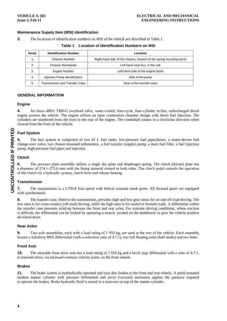
48. Two sedimenters (refer to Figure 12) are incorporated in the fuel lines between the fuel tanks and the transfer pump to trap any water or heavy contaminants that may be in the fuel. A drain plug in the bottom of each sedimenter housing allows any water or contaminants to be drained off. The sedimenter is mounted on the chassis rail behind the fuel tank.
Figure 12 Fuel Sedimenter
49. The transfer (supply) pump is a self-regulating, mechanical type, attached to the side of the fuel injection pump and driven by the injection pump camshaft. The transfer pump supplies fuel at a pressure of 176–245 kPa (25.5–35.5 psi) to the fuel filter and the injection pump. A strainer, incorporated in the transfer pump fuel inlet bolt, filters out coarse particles in the fuel, preventing premature wear and damage to the internal components of the transfer pump.
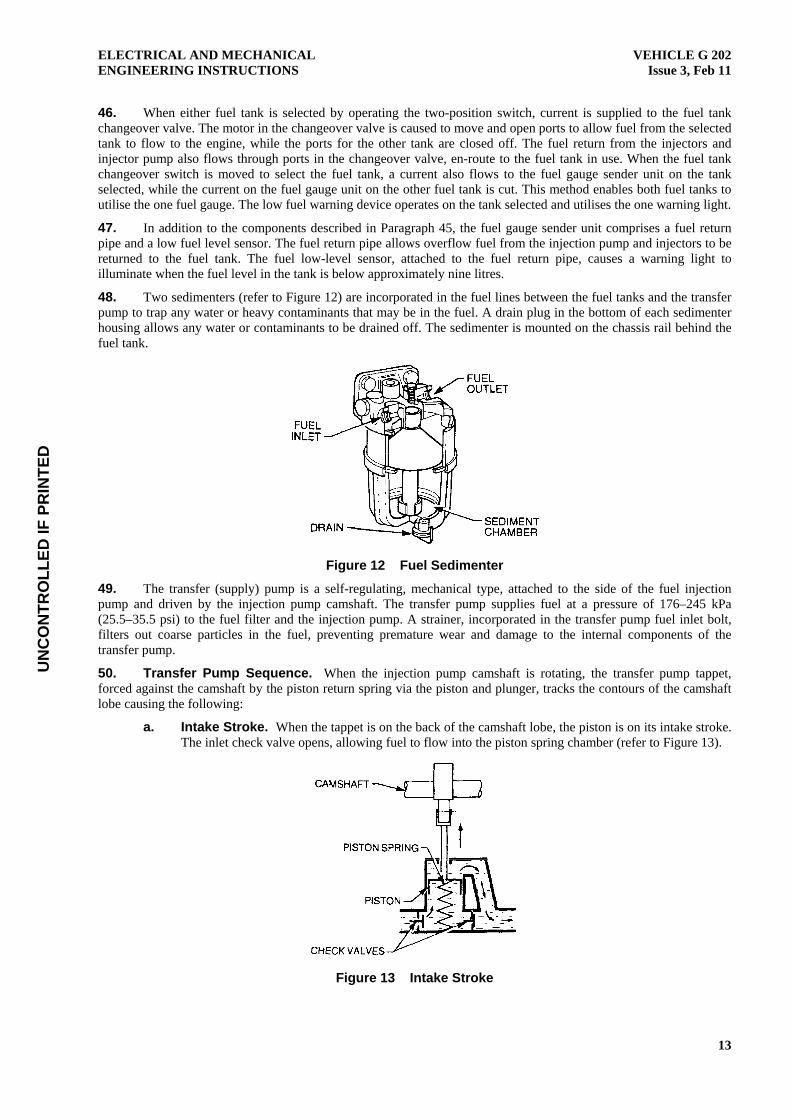
50. Transfer Pump Sequence. When the injection pump camshaft is rotating, the transfer pump tappet, forced against the camshaft by the piston return spring via the piston and plunger, tracks the contours of the camshaft lobe causing the following:
a. Intake Stroke. When the tappet is on the back of the camshaft lobe, the piston is on its intake stroke. The inlet check valve opens, allowing fuel to flow into the piston spring chamber (refer to Figure 13).
Figure 13 Intake Stroke

UN
CO
NTR
OLL
ED IF
PR
INTE
D
VEHICLE G 202 Issue 3, Feb 11
ELECTRICAL AND MECHANICAL ENGINEERING INSTRUCTIONS
14
b. Discharge Stroke. As the camshaft rotates and forces the piston back into the spring chamber, the inlet check valve closes, causing the fuel pressure to increase and open the outlet valve (refer to Figure 14). The fuel flows through the outlet valve and around to the chamber on the plunger side of the piston. As the camshaft continues to rotate, the spring pressure acting on the piston causes the piston to force the fuel out of the chamber on the plunger side of the piston. The fuel pressure closes the outlet valve, causing the fuel to flow through the pump outlet port to the fuel filter.
Figure 14 Discharge Stroke
c. Pump Pressure Regulation. When fuel supply exceeds the demand, the fuel pressure acting on the plunger side of the piston becomes equal to the force exerted by the piston spring, causing the piston to remain stationary (refer to Figure 15). At this stage, no further pumping action takes place until the fuel pressure in the injection pump fuel gallery drops, causing the fuel pressure in the transfer pump to drop.
Figure 15 Pump Pressure Regulating
51. The main fuel filter, located at the front right-hand side of the engine, is comprised of a mounting adaptor, a removable housing, a disposable cartridge and a drain plug (refer to Figure 16). Due to the fine tolerances required for the injection pump components and the injectors, the fuel filter is designed to remove contaminants from the fuel in sizes of 100 microns or larger.
Figure 16 Main Fuel Filter

UN
CO
NTR
OLL
ED IF
PR
INTE
D
ELECTRICAL AND MECHANICAL ENGINEERING INSTRUCTIONS
VEHICLE G 202Issue 3, Feb 11
15
52. The injection pump is an in-line, A-type, located on the right-hand side of the engine and driven by the engine camshaft driving gear. Located within the injection pump housing are four plunger and barrel assemblies (one assembly for each of the engine cylinders) and a camshaft. The plunger and barrel of each assembly are finely ground and assembled together with extremely fine tolerances, forming a matched pair, and should never be intermixed with other plungers or barrels.
Fuel Metering
53. The plungers used in the injection pump are 9.5 mm in diameter and have a centre bore drilling, instead of the more common external groove. A lower helix, which rises diagonally to the left giving a left lead, is machined into the side of the plunger (refer to Figure 17).
Figure 17 Plunger
54. The barrels in which the plungers operate have an inlet/spill port, machined through the side into the bore (refer to Figure 18). When the barrel is installed in the injection pump, the port aligns with the fuel gallery in the injection pump. Fuel supply for the plunger flows from the fuel gallery, through the inlet/spill port and into the high-pressure chamber above the plunger.
Figure 18 Barrel – Sectional View
55. As the stroke of the plunger is 8 mm, regardless of engine load or speed, the amount of fuel delivered to the injectors is regulated by the position of the helix in regard to the inlet/spill port. With the lowest point of the helix aligned with the inlet/spill port, maximum fuel delivery is achieved. As the plunger is rotated clockwise (when viewed from the bottom of the plunger), the quantity of fuel delivered is reduced with each stroke of the plunger. As the engine operates over varying loads and speeds, the fuel requirements of the engine also vary. To adjust the fuel delivery to suit the engine requirements, a control sleeve with a toothed segment clamped to its upper section and a toothed control rack are utilised. The barrel is installed into the sleeve from the top, while the plunger is installed from the bottom, with the control arms on the plunger stem positioned in the two longitudinal slots machined into the bottom of the control sleeve. When installed in the injection pump, the toothed segment of the sleeve meshes with the toothed control rack, which is mounted longitudinally in a bore within the body of the injection pump and free to move in that bore.

UN
CO
NTR
OLL
ED IF
PR
INTE
D
VEHICLE G 202 Issue 3, Feb 11
ELECTRICAL AND MECHANICAL ENGINEERING INSTRUCTIONS
16
56. Both the accelerator and the injection pump governor regulate movement of the control rack. The accelerator is used for the initial or main movement of the rack, to enable the engine to reach the required pulling power, while the governor makes finer adjustments to the rack, to enable the engine to maintain that power over varying road conditions. As the accelerator pedal is depressed, the rack moves accordingly causing the control sleeve to rotate. The plunger, which is connected to the control sleeve via the control arms, also rotates moving the helix towards the lower point in relation to the barrel inlet/spill port, which is secured in a fixed position within the pump body. Figure 19 illustrates the plunger rotating mechanism, showing the plunger helix to barrel inlet/spill port relationship in non-delivery, partial delivery and maximum delivery positions.
Figure 19 Plunger Rotating Mechanism
57. The injection pump camshaft has four tangential-shaped lobes. When installed in the injection pump body, each camshaft lobe is positioned directly below a plunger and barrel assembly. The camshaft rotates in accordance with the engine’s timing gear. The camshaft lobes act on the roller tappets, shims, spring seats and return springs causing the plungers to move up and down within the bore of the barrel (refer to Figure 20). The camshaft drives the pump plunger and influences the duration of injection, the pump delivery, and the rate of delivery by the amount of lift and the profile of the camshaft lobe.
Figure 20 Plunger Drive Assembly

UN
CO
NTR
OLL
ED IF
PR
INTE
D
ELECTRICAL AND MECHANICAL ENGINEERING INSTRUCTIONS
VEHICLE G 202Issue 3, Feb 11
17
58. A housing is placed over the plunger and barrel assembly to enable the fuel to be pumped under high pressure to the injectors. A delivery valve and return spring are incorporated within the housing. When the housing is installed over the plunger and barrel assembly in the injection pump body, it effectively seals the area above the plunger, creating a high-pressure chamber (refer to Figure 21).
Figure 21 Housing and Delivery Valve Location
59. With the plunger at the bottom of its stroke (BDC), the inlet/spill port is open, allowing fuel under low pressure to flow from the injection pump fuel gallery into the high-pressure chamber. As the camshaft rotates, causing the plunger to move towards the top of its stroke (TDC), a series of phases called strokes take place (refer to Figure 22) as follows:
a. Pre-stroke is the closing-off of the inlet spill port by the plunger.
b. Effective stroke occurs when the pressure of the fuel above the plunger has attained the point where the delivery valve is lifted off its seat, against the return spring pressure, allowing the high-pressure fuel to flow to the injectors.
c. Residual stroke occurs after the plunger helix has uncovered the inlet spill port, allowing the high-pressure fuel above the plunger to spill out into the injection pump fuel gallery, via the plunger centre bore and helix.
Figure 22 Phases (Strokes) of the Plunger

UN
CO
NTR
OLL
ED IF
PR
INTE
D
VEHICLE G 202 Issue 3, Feb 11
ELECTRICAL AND MECHANICAL ENGINEERING INSTRUCTIONS
18
Fuel Injectors
60. The pressurised fuel from the injection pump passes along high-pressure fuel lines to the four fuel injector nozzle assemblies mounted in the cylinder head, with the nozzle of each assembly protruding into the combustion chamber. After the pressurised fuel enters the nozzle holder body, it passes through a high-pressure fuel duct into a pressure chamber and down alongside the nozzle needle in the nozzle body (refer to Figure 23). The high-pressure fuel in the pressure chamber acts against the exposed annular area on the nozzle needle, pushing the nozzle needle and spindle up against spring pressure; opening the needle seat and allowing the fuel to flow out through the orifices, where it is sprayed into the combustion chamber.
Figure 23 Fuel Injector Assembly
61. A small amount of fuel leakage takes place during fuel injection. The fuel seeps between the nozzle needle and the nozzle body, cooling and lubricating the needle and body as it does so. This fuel is then returned to the fuel tank via the injection pump overflow valve.
Injection Pump Governor
62. The governor is attached to the back of the injection pump. It is a variable speed control type, which not only controls the idle and maximum speed of the engine, but also maintains maximum torque output under varying loads and conditions, at selected speeds between idle and the maximum no-load speed. Using flyweights, springs, rods and levers, the governor ensures that the engine does not stall when in the idle-speed range and that the maximum engine speed is not exceeded. When the engine is operating between idle and maximum speed, a torque cam and a sensor lever regulate the position of the control rack which, in turn, regulates the amount of fuel injected to maintain the engine at the required torque output.

UN
CO
NTR
OLL
ED IF
PR
INTE
D
ELECTRICAL AND MECHANICAL ENGINEERING INSTRUCTIONS
VEHICLE G 202Issue 3, Feb 11
19
63. Figure 24 illustrates the governor assembly showing the location of the various components.
Figure 24 Governor Assembly
64. The flyweight holder (refer to Figure 25) is secured to the rear of the injection pump camshaft by means of a taper, woodruff key and a lock nut. The flyweights are secured to the holder by press-fit pins, around which the flyweights pivot. When the camshaft revolves, the flyweight holder and the flyweights revolve with it. As the camshaft speed increases, the flyweights move outward due to centrifugal force. This action causes the sliders, which are fixed to the arms on the flyweights, to push against a sleeve which causes the sleeve to move in an axial direction (refer to Figure 26).
Figure 25 Flyweights Closed

UN
CO
NTR
OLL
ED IF
PR
INTE
D
VEHICLE G 202 Issue 3, Feb 11
ELECTRICAL AND MECHANICAL ENGINEERING INSTRUCTIONS
20
Figure 26 Flyweights Open
65. As the sleeve moves, it pushes against the shifter (which rides in the bearing in the end of the sleeve) causing the shifter to move in an axial direction. The shifter, which is connected to the tension lever by a pivot pin, causes the tension lever (which is shaft mounted to the governor cover) to pivot on the shaft. As the lower section of the tension lever moves away from the pump body, the upper section moves toward the pump body. A spring seat is attached by a pin to the upper section of the tension lever with the governor shaft running through the centre bore of the spring seat. The governor shaft is secured to the governor cover at one end by a guide-screw. The other end of the shaft is mounted in a bore in the governor housing (refer to Figure 27).
Figure 27 Tension Lever and Governor Shaft
66. A spring seat is positioned on the governor shaft at the housing end. The governor springs are installed on the governor shaft and held uncompressed between the two seats. An idling spring capsule is positioned toward the bottom of the governor cover. The adjustable capsule houses the idling spring, which butts against the back of the shifter (refer to Figure 28). The combination of the governor springs and the idling spring counter the centrifugal force of the flyweights over the entire engine speed range, ensuring that the setting of the tension lever, in the position appropriate to the amount of flyweight lift, is smooth and progressive.
Figure 28 Governor Springs and Idling Spring Locations

UN
CO
NTR
OLL
ED IF
PR
INTE
D
ELECTRICAL AND MECHANICAL ENGINEERING INSTRUCTIONS
VEHICLE G 202Issue 3, Feb 11
21
67. The guide lever is also mounted on the tension lever shaft and is concentric with the tension lever. Both levers are held together by the force of the cancel spring (1) as shown in Figure 29. A ball joint is welded to the top of the guide lever.
Figure 29 Guide Lever and Cancel Spring (1) Location
68. The connecting link, which has a ball joint welded to it, is secured to the end of the injection pump control rack by a bolt; nut and washer (refer to Figure 30). The start spring is connected to the connecting link and to the spring eye, which is bolted to the governor housing. The spring always works to pull the control rack into the fuel increase direction.
Figure 30 Connecting Link and Start Spring Location
69. The control lever assembly, which is installed in the governor cover, comprises a floating lever, supporting lever, cancel spring, control lever shaft and a control lever. The centre drilling of the floating lever is positioned on the lower pivot pin on the supporting lever and secured in place by a snap-ring. The supporting lever and the cancel spring (2), as shown in Figure 31, are positioned on the lower end of the control lever shaft and secured by a snap-ring. The force of the cancel spring (2) keeps the elbow on the control lever shaft in contact with the supporting lever. This assembly fits up through the governor cover and the control lever is positioned on the control lever shaft and secured by a nut. The forked ends of the floating lever engage with the tension lever ball joint at one end and the control rack connecting link ball joint at the other. The control lever assembly forms the mechanical linkage between the accelerator cable and the injection pump fuel control rack and also between the governor assembly and the injection pump fuel control rack.
Figure 31 Control Assembly – Exploded View

UN
CO
NTR
OLL
ED IF
PR
INTE
D
VEHICLE G 202 Issue 3, Feb 11
ELECTRICAL AND MECHANICAL ENGINEERING INSTRUCTIONS
22
70. A torque cam is mounted on a pivot pin, which is pressed into the inside of the governor cover on the control rack side. A rod, spring and adjusting nut connects the cam to the spring seat pin on the tension lever. The torque cam pivots on the pin in accordance with the movement of the tension lever, or by adjusting the length of the connecting rod (refer to Figure 32).
Figure 32 Torque Cam Location
71. The shaft for the full-load setting lever is installed in the governor housing. As shown in Figure 33, the cancel spring (3) is installed over the end of the shaft inside the housing. The U-shaped lever is positioned in the housing, with one end located by a guide screw (on the control rack side of the housing). The other end is mounted on the end of the shaft against the cancel spring. The sensor lever is mounted on a pivot pin on the U-shaped lever on the control rack side. The full-load setting lever, together with a return spring, is secured by a nut and washer to the full-load setting lever shaft on the outside of the governor housing. The full-load setting lever (refer to Figure 33) is always forced against the adjustable full-load setting bolt (also located outside the governor housing) by the return spring (3).
Figure 33 Full-load Setting Lever and Sensor Lever Locations
72. With the engine stationary (the injection pump not operating), depressing the accelerator pedal causes the control lever to move toward the maximum speed position. In so doing, the cancel spring (2) causes the supporting lever and the floating lever to move with the control lever (refer to Figure 34).
Figure 34 Control Lever Assembly Operation

UN
CO
NTR
OLL
ED IF
PR
INTE
D
ELECTRICAL AND MECHANICAL ENGINEERING INSTRUCTIONS
VEHICLE G 202Issue 3, Feb 11
23
73. As the guide lever ball joint is held stationary, the floating lever pivots on this ball joint, causing the control rack to move in the fuel increase direction (refer to Figure 35). By depressing the accelerator pedal fully, the control lever moves to the maximum speed position causing the elbow on the control lever shaft to move away from the supporting lever. The cancel spring (2) then forces the supporting lever to move toward the elbow causing the floating lever to pivot on the stationary guide lever ball joint and move the control rack to the starting position. In this position, the sensor lever engages with the notch of the torque cam, which controls the engine’s starting fuel injection quantity. The governor and the injection pump are now in the engine start position.
Figure 35 Engine Start Position
Do not allow the engine to rev up after it starts. This will prevent the sensor lever from disengaging from the notch on the torque cam and dangerously interfering with the governor control of the injection pump.
74. With the engine started and the accelerator pedal released, the control lever returns to contact the idle speed-setting bolt. The control rack moves to decrease the fuel injection quantity and the edge of the sensor lever is released from the torque cam notch (refer to Figure 36).
Figure 36 Returning to the Idle Position
UN
CO
NTR
OLL
ED IF
PR
INTE
D
VEHICLE G 202 Issue 3, Feb 11
ELECTRICAL AND MECHANICAL ENGINEERING INSTRUCTIONS
24
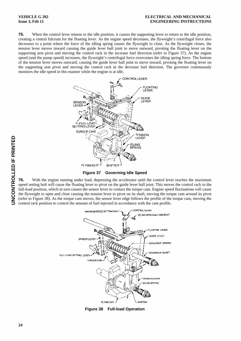
75. When the control lever returns to the idle position, it causes the supporting lever to return to the idle position, creating a central fulcrum for the floating lever. As the engine speed decreases, the flyweight’s centrifugal force also decreases to a point where the force of the idling spring causes the flyweight to close. As the flyweight closes, the tension lever moves inward causing the guide lever ball joint to move outward, pivoting the floating lever on the supporting arm pivot and moving the control rack in the increase fuel direction (refer to Figure 37). As the engine speed (and the pump speed) increases, the flyweight’s centrifugal force overcomes the idling spring force. The bottom of the tension lever moves outward, causing the guide lever ball joint to move inward, pivoting the floating lever on the supporting arm pivot and moving the control rack in the decrease fuel direction. The governor continuously monitors the idle speed in this manner while the engine is at idle.
Figure 37 Governing Idle Speed
76. With the engine running under load, depressing the accelerator until the control lever reaches the maximum speed setting bolt will cause the floating lever to pivot on the guide lever ball joint. This moves the control rack to the full-load position, which in turn causes the sensor lever to contact the torque cam. Engine speed fluctuations will cause the flyweight to open and close causing the tension lever to pivot on its shaft, moving the torque cam around its pivot (refer to Figure 38). As the torque cam moves, the sensor lever edge follows the profile of the torque cam, moving the control rack position to control the amount of fuel injected in accordance with the cam profile.
Figure 38 Full-load Operation

UN
CO
NTR
OLL
ED IF
PR
INTE
D
ELECTRICAL AND MECHANICAL ENGINEERING INSTRUCTIONS
VEHICLE G 202Issue 3, Feb 11
25
77. While the control lever is in contact with the maximum speed setting bolt, engine speed can increase while the fuel injection quantity is controlled by the torque cam and the sensor lever. With the supporting lever in contact with the elbow on the control lever shaft, an increase in engine speed causes the guide lever to move toward the fuel injection pump. This pivots the floating lever on the supporting lever pivot and moves the control rack toward the decrease fuel position, decreasing the fuel injection quantity for maximum speed governing. The sensor lever edge disengages from the torque cam for maximum speed governing (refer to Figure 39). The stop control lever moves the rack to the no-fuel position when the ignition is turned off.
Figure 39 Maximum Speed Control
Automatic Timer
78. The injection pump is equipped with an automatic timer, which forms the drive connection between the engine’s timing gears and the injection pump camshaft. The purpose of the automatic timer is to reduce ignition lag, which, if excessive, causes diesel knock. The automatic timer is designed to advance the injection timing as the engine speed increases, thus allowing additional time for fuel and air in the combustion chamber to form an ignitable mixture, which then ignites at the correct time.

UN
CO
NTR
OLL
ED IF
PR
INTE
D
VEHICLE G 202 Issue 3, Feb 11
ELECTRICAL AND MECHANICAL ENGINEERING INSTRUCTIONS
26
79. The automatic timer achieves this function by means of flyweights, springs and eccentric cams (refer to Figure 40).
Figure 40 Automatic Timer – Exploded View
80. When the engine is operating at idle speed, the setting force of the four springs prevents the flyweights from expanding outward, but as the engine speed is gradually increased, the centrifugal force of the flyweights overcomes the setting force of the springs and the flyweights begin to expand outward. When the flyweights expand radially, the pivot pins connecting the flyweights to the large eccentric cams cause the large cams to rotate within the machined holes in the timing flange. The rotation of the large cams affects the small eccentric cams, which are located in the machined holes in the large cams and connected by pivot pins to the drive flange. As the large cams rotate in accordance with the movement of the flyweights, the small cams, which are held in position by the pivot pins on the drive flange, are caused to rotate around the pivot pins and within the large cams. The combined rotational movement of the large and small cams causes the timing flange to turn ahead of the drive flange and gear timing mark, and because the timing flange is connected directly to the injection pump camshaft. The injection timing also advances the same amount (refer to Figure 41). The timing flange limits the outward movement of the flyweight, which in turn limits the injection-timing advance, regardless of any engine speed increase.
Figure 41 Automatic Timer – Static Position

UN
CO
NTR
OLL
ED IF
PR
INTE
D
ELECTRICAL AND MECHANICAL ENGINEERING INSTRUCTIONS
VEHICLE G 202Issue 3, Feb 11
27
81. When the engine speed is decreased to below that of maximum timing advance, the flyweight return springs overcome the centrifugal force of the flyweights and move the flyweights toward their static position. Both the large and small eccentric cams rotate in the reverse direction, moving the timing flange and fuel injection pump camshaft toward the normal timing mark (refer to Figure 42).
Figure 42 Flyweights in Timing Advance Position
Turbocharger
82. A turbocharger is fitted to the engine manifold and driven by exhaust gas energy. The turbocharger comprises three main components: the turbine, the bearing housing and the compressor.
83. The turbine consists of a housing and a wheel and shaft (which are manufactured in one piece), with the shaft mounted in sleeve type bearings located in the bearing housing. The bearings are pressure lubricated and cooled by oil from the engine lubricating system. Piston ring type seals are used at each end of the turbine shaft to effectively contain the oil to the bearing housing. Coolant from the engine cooling system flows through a water jacket surrounding the bearing housing, assisting with the cooling of the bearings.
84. The compressor impeller is secured to the end of the turbine shaft and rotates as one with the turbine. The turbine and compressor housings are positioned over their respective wheels and secured to the bearing housing. The turbocharger assembly is then secured to the exhaust manifold via the turbine-housing flange.
85. When the engine is running, the exhaust gas flowing from the exhaust manifold enters the turbine housing, where it flows radially inward increasing in velocity as the chamber decreases in size. The exhaust gas then flows through the specially designed vanes of the turbine, causing the turbine to spin as the gas passes through and enters the exhaust system.
86. As the turbine spins, the compressor impeller also spins, drawing air from the air cleaner through the central inlet of the compressor housing and then forcing the air into the chamber within the housing. The air then flows radially outward, through the diffuser, which enlarges in diameter as it winds outward to the crossover tube through which it flows to the inlet manifold.
87. As the compressor impeller draws in more air than the engine uses, the air accumulates in the crossover tube and inlet manifold where it increases in pressure. The pressure build-up of the air in the manifold causes additional air to flow into each cylinder as the inlet valves open, promoting a more complete combustion of the fuel, which in turn increases engine power and performance.

UN
CO
NTR
OLL
ED IF
PR
INTE
D
VEHICLE G 202 Issue 3, Feb 11
ELECTRICAL AND MECHANICAL ENGINEERING INSTRUCTIONS
28
Always allow several seconds for oil pressure to build-up before accelerating the engine. Turbocharger bearing damage can occur when the turbocharger is operated at high speed without lubricant. This also applies when shutting down the engine. If the engine is shut down immediately after operating at a high rpm for an extensive period, the turbocharger will continue to rotate at a high rpm without lubricant. This in conjunction with the heat build-up during operation can easily cause turbocharger damage. Always allow the engine to idle for several minutes prior to shut down to allow the heat to dissipate and the rotational speeds of the turbochargers to slow down.
88. Good lubrication of the turbocharger bearings is essential because the turbocharger is precision machined and delicately balanced and operates at speeds in excess of 70 000 rpm. However, because the engine lubricating system lubricates the turbocharger, the delivery of oil to the turbocharger at engine start-up is not immediate.
Exhaust System
89. The engine exhaust system consists of a muffler and two pipes. Both pipes are constructed of aluminised steel tubing, with the front (engine) pipe being 57 mm in diameter and the rear pipe 51 mm in diameter. The muffler has one inlet pipe and one outlet pipe and is connected to both the engine pipe and the rear pipe by flange connections.
90. The engine pipe is connected to the turbocharger outlet by means of a flange, with a gasket between the flange connections to prevent exhaust gas leakage. The muffler and the rear pipe are supported by means of three U-bolt clamps, which are suspended from chassis cross members by bolts and rubber bushes (refer to Figure 43).
Figure 43 Exhaust System
Clutch
91. The clutch plate used on the vehicle is a spring-dampened single disc with linings riveted to both sides. The pressure plate used is a diaphragm-type, which utilises a Belleville-type spring to apply a load to the pressure plate. Both the clutch plate and the pressure plate are mounted on the flywheel, although only the pressure plate is secured to the flywheel. The clutch plate is held in position by the transmission input shaft (to which the clutch plate is splined) and the pressure plate.
92. The Belleville spring is secured to the pressure plate housing. Ridging on the inside of the pressure plate housing acts as a pivot, causing the Belleville spring to apply a load to the pressure plate when in the released position. This action clamps the clutch plate between the flywheel and pressure plate, causing drive from the flywheel to be transmitted to the transmission input shaft via the clutch plate.

UN
CO
NTR
OLL
ED IF
PR
INTE
D
ELECTRICAL AND MECHANICAL ENGINEERING INSTRUCTIONS
VEHICLE G 202Issue 3, Feb 11
29
93. To enable gear changes to be made while the vehicle is moving, drive from the flywheel to the transmission input shaft must be interrupted. This is to allow the rotational speeds of the various shafts and gears within the transmission housing to come into close alignment, making gear selection easier and smoother.
94. The break in the drive from the flywheel to the transmission is achieved by means of the clutch pedal, hydraulic circuit, the release lever and a release bearing (refer to Figure 44). When the clutch pedal is depressed, a plunger attached to the clutch pedal lever acts on the piston in the clutch master cylinder, displacing hydraulic fluid from the bore of the master cylinder. The hydraulic fluid is forced from the master cylinder to the slave cylinder, via pipes and hose. The pressurised hydraulic fluid acts on the piston in the slave cylinder, forcing the piston outward. A plunger attached to the piston pushes against the release lever which, because of a pivot mounting, pushes against the release bearing, causing the bearing to depress the inner circumference of the Belleville spring. This action causes the outer circumference of the Belleville spring to remove the load it applied to the pressure plate, which in turn relieves the clamping effect applied to the clutch plate, allowing the clutch plate to come away from the flywheel and stop transmitting drive to the transmission.
Figure 44 Clutch Assembly – Sectional View
Transmission
95. The transmission consists of two aluminium alloy housings; the bell housing, and the transmission and transfer case housing. The bell housing not only connects the transmission to the engine, but also houses the clutch assembly, the clutch release mechanism and the transmission input (pinion) shaft. A drain plug is located in the bottom of the flywheel housing to provide a means of draining off contaminants, which may have entered the bell housing during fording.
96. The transmission and transfer case housing is actually two separate sections utilising the one casting. The transmission section contains the input shaft, countershaft, reverse idle gear, mainshaft and gear selectors. The transfer case, located at the rear of the casting, contains the mainshaft transfer gear, an intermediate gear assembly and a differential assembly for the transmission output. Both the transmission and the transfer case have their own selector levers as well as individual drain and fill plugs.
97. The transmission input shaft, together with the top gear (fourth), is machined from one solid forging. A counter bore in the gear end of the shaft provides housing for the mainshaft front bearing. The countershaft, with its five gears, is also machined from a solid drop forging and is supported at each end by pre-loaded taper roller bearings. An oil pump, driven by the countershaft, ensures that the mainshaft is constantly supplied with oil. The mainshaft is supported by three bearings: a needle roller bearing at the front, a ball bearing in the centre and a needle roller bearing at the rear. The mainshaft is fitted with four helical cut gears and two synchroniser units. Reverse gear is formed on the outer circumference of the rear synchroniser unit. When the gears and synchronisers are installed on the mainshaft, they are located from the front (refer to Figure 45), third/fourth gear synchroniser, third gear,

UN
CO
NTR
OLL
ED IF
PR
INTE
D
VEHICLE G 202 Issue 3, Feb 11
ELECTRICAL AND MECHANICAL ENGINEERING INSTRUCTIONS
30
second gear, first/second gear synchroniser, first gear and the mainshaft transfer gear (which is located in the transfer case section). The reverse idler gear, which is a spur tooth pinion supported on needle roller bearings and mounted on its own shaft, is also located in the transmission section. Unlike the forward gears that utilise the synchroniser unit to engage the selected gear, the reverse idler gear is moved to mesh with the spur gear on the countershaft and the spur gear on the first/second gear synchroniser. Because the idler gear transmits drive from the countershaft to the mainshaft via the synchroniser, the mainshaft is made to turn in the opposite direction to the normal direction of rotation, thus giving the vehicle a reverse gear.
98. Drive is transmitted from the engine via the clutch plate and input shaft to the countershaft, which is in constant mesh with the input shaft gear (fourth gear). When a forward gear is selected (other than fourth), drive is transmitted from the countershaft to the mainshaft via the selected gear and the synchroniser unit. First, second and third gears are also in constant mesh with the countershaft, but as these gears are supported by needle roller bearings on the mainshaft, they cannot transmit drive directly to the mainshaft. Drive is only transmitted to the mainshaft by the synchroniser units, which are splined to the mainshaft, but are able to slide back and forth to engage with the selected gear and transmit drive from that gear to the mainshaft. Drive from fourth (top) gear is transmitted directly to the mainshaft, bypassing the countershaft, but only when the synchroniser unit is engaged with fourth gear.
Figure 45 Transmission Assembly – Sectional View
99. Figure 46 shows drive through the forward gears.

UN
CO
NTR
OLL
ED IF
PR
INTE
D
ELECTRICAL AND MECHANICAL ENGINEERING INSTRUCTIONS
VEHICLE G 202Issue 3, Feb 11
31
Figure 46 Drive Transmitted Through the Gears
Transfer Case
100. The transfer case enables drive from the transmission to be directed to both the front and intermediate axles simultaneously and provides two extra gear ratios, a low and a high, effectively giving the vehicle a total of eight forward gears and two reverse gears. The low ratio, when selected, is used where low speed and high-torque output are required, while the high ratio is used for normal driving.
101. The mainshaft transfer gear and the intermediate shaft central input gear are in constant mesh with each other allowing drive from the transfer gear to be transmitted directly to the central input gear. As the central input gear is supported on the intermediate shaft by two tapered roller bearings, drive from the input gear cannot be transmitted to the intermediate shaft. However, a sliding dog clutch, incorporated with the central input gear and moved by a selector lever and fork, enables the drive to be transmitted to enter the high or low gear ratios. Although both of these gears are each supported by two tapered roller bearings on the intermediate shaft, they are both in constant mesh with gears on the differential assembly (refer to Figure 47). When either the high or low ratio gear is engaged with the central input gear (via the sliding dog clutch), drive can be transmitted from the central input gear to the differential then out to the front and intermediate axles.
102. The two-piece differential case, mounted on two tapered roller bearings in the transfer case, operates in the same manner as a drive axle differential. The differential casing carries two driven gears, the smaller gear being the high ratio and the larger gear, the low ratio. The casing also houses four bevel pinion gears and thrust washers, two side gears and one cross shaft (refer to Figure 47). The six gears are installed as a matched set. Front and rear output shafts are installed in the differential and engage with the splines in the side gears. As the differential casing revolves, so do the output shafts, transmitting drive to the front and intermediate axles. The intermediate axle output shaft carries the speedometer drive gear, while the front axle output shaft and the rear axle output shafts each carry a dog clutch. The clutches are utilised when positive all-wheel drive is required. When operated, the dashboard-mounted, differential-lock-control switch supplies vacuum to the forward side of the two-way diaphragms, which are located adjacent to the dog clutches on both the front and rear axle output shafts. The rear side of the diaphragms is vented to the atmosphere via the control switch. The vacuum supply causes deflection of the two diaphragms, which move the selector mechanisms, locking the front output shaft to the differential casing, and the rear output shaft to the output shaft gear (which is in constant mesh with the low ratio gear on the differential casing) via the dog clutches. In so doing, the differential action between the front and intermediate axle output shafts is now locked out and positive drive is now provided to the three output shafts.

UN
CO
NTR
OLL
ED IF
PR
INTE
D
VEHICLE G 202 Issue 3, Feb 11
ELECTRICAL AND MECHANICAL ENGINEERING INSTRUCTIONS
32
Figure 47 Transfer Case and Differential – Sectional View
103. When positive drive is no longer necessary and the switch is pushed in, the forward side of both of the vacuum chamber diaphragms is now vented to the atmosphere, while vacuum is applied to the rear side of the diaphragms. The deflection of the diaphragms causes the selector mechanisms to move and disengage the dog clutches from the differential casing and from the low gear on the differential casing. This action stops the positive drive from being transmitted to the three axles and allows the transfer case differential to resume normal operation, transmitting drive to the front and intermediate axles only. The rear axle now acts as a trailing axle only and does not contribute to the propelling of the vehicle.
Power Take-off (PTO)
104. Vehicles equipped with a winch utilise a transmission drive PTO to provide drive to the winch. The PTO is mounted on the transmission housing below the transfer case (refer to Figure 48). An endless chain transfers drive from the sprocket on the transmission mainshaft to the sprocket on the PTO output shaft. The sprocket on the PTO output shaft is supported on the shaft by two bearings, a ball type and a roller type, and thus revolves freely on the shaft. When the PTO control is moved to the engaged position, the sliding clutch on the torque limiter moves along the splines and engages with the dog clutch on the PTO sprocket.
Figure 48 PTO Location

UN
CO
NTR
OLL
ED IF
PR
INTE
D
ELECTRICAL AND MECHANICAL ENGINEERING INSTRUCTIONS
VEHICLE G 202Issue 3, Feb 11
33
105. Drive from the transmission is now transmitted from the PTO sprocket to the torque limiter (refer to Figure 49). If the load applied to the winch is less than the maximum recommended load, the torque limiter will transmit the drive to the PTO output shaft, which transmits the drive to the winch via the propeller shaft. If the load applied to the winch exceeds the maximum recommended load, the torque required to drive the winch will exceed the torque setting of the torque limiter. Should this occur, the torque limiter will slip preventing the drive being transmitted to the PTO output shaft and, therefore, to the winch. This action protects the winch from damage due to overloading. The torque limiter will automatically reset itself when the excessive load is removed, allowing normal winching operations to proceed.
Figure 49 PTO and Torque Limiter Assembly
Torque Limiter
106. The torque limiter (refer to Figure 50) is incorporated as part of the PTO assembly and used to prevent winch overload. The torque limiter is comprised of a drive hub, a sliding clutch, twelve steel balls and coil springs, a steel spacer, a drive flange, an output shaft and two bearings (a ball type and a roller type).
Figure 50 Torque Limiter and Output Shaft – Exploded View
107. The drive hub is supported on the output shaft by both the roller and the ball bearings, and revolves freely on the shaft. The twelve coil springs and steel balls are installed in four groups of three in the sixteen hole drive hub with the steel balls protruding. When the components are assembled, the steel balls sit in the indents in the drive flange and transmit the drive from the drive hub to the drive flange. When a winch overload occurs, the steel balls are caused to jump from one indent to the next as the drive flange stalls under load and the drive hub keeps turning. The steel spacer, which is available in varying thicknesses, is used to set the pre-load of the steel balls in the indents by altering the clearance between the drive hub and the drive flange. When the correct clearance is set, a torque of 155 N.m (114.322 lbf.ft) is required to turn the drive hub while the drive flange is held stationary, thus creating a safe working limit for the winch.

UN
CO
NTR
OLL
ED IF
PR
INTE
D
VEHICLE G 202 Issue 3, Feb 11
ELECTRICAL AND MECHANICAL ENGINEERING INSTRUCTIONS
34
108. A cable connects the control lever (located on the seat base below the driver’s seat) to the selector lever on the PTO housing. A selector fork, located in the PTO housing, connects the selector lever to the sliding clutch, which engages with the dog clutch on the PTO sprocket when the control lever is pulled to the engage position.
Propeller Shafts
109. Two propeller shafts (refer to Figure 51) are used on the vehicle to transmit drive from the transfer case output shafts to both the front and intermediate axles. Both propeller shafts are constructed with a sliding (slip) joint and two single needle roller-type universal joints. A two-piece shaft is used to transmit drive to the rear (limiting) axle. The front section of the shaft incorporates a single joint and a rubber-mounted centre bearing, which is secured to the chassis cross member. The rear section of the shaft incorporates a double joint, a slip joint and a single joint. The sliding joints allow the length of the propeller shafts to vary in accordance with the position of the axles, as the axles move up or down. A grease nipple is fitted to the sliding joint for ease of maintenance. The universal joints allow drive to be transmitted to the axle through varying angles, which are caused by the vertical movement of the axle and suspension. The universal joints are maintenance free and are serviced by replacement.
Figure 51 Front, Intermediate and Rear Propeller Shafts
Rear Axles
110. The rear axle assemblies (refer to Figure 52) transmit drive from the propeller shaft to the rear axles, hubs and wheels. Each utilises a differential to achieve this. The differential is comprised of a crown wheel and pinion; two side gears which are spline connected to the axle shafts; four planetary bevel gears; and a cross-shaft, which not only locates the planetary bevel gears but also forms the axis about which each planetary gear rotates. With the Salisbury differential, the differential carrier is incorporated in the axle housing and cannot be removed. To gain access to the differential, a cover plate must be removed from the rear of the axle housing. The crown wheel and differential case assembly is supported by two tapered roller bearings, as is the pinion. The axles are splined at both ends, with one end installed in the differential side gears and the other end installed in the drive flange, which is bolted to the hubs. The hubs are supported on two tapered roller bearings on the axle housing spindles. A lock nut and an adjusting nut secure the hub to the spindle.

UN
CO
NTR
OLL
ED IF
PR
INTE
D
ELECTRICAL AND MECHANICAL ENGINEERING INSTRUCTIONS
VEHICLE G 202Issue 3, Feb 11
35
Figure 52 Intermediate and Rear Axle Assemblies
111. Drive from the propeller shaft is transmitted by the pinion to the crown wheel. The differential case, to which the crown wheel is bolted, carries the planetary gears, cross shaft and side gears. When the vehicle is moving in a straight line, without wheel slip, the differential case assembly rotates with the crown wheel causing the axles, hubs and wheels on both sides to rotate simultaneously. When a corner or bend is encountered, the planetary gears and the side gears begin to operate. Because of the different arcs both drive wheels must take through a corner, the inside wheel, i.e. the one which uses the smaller arc, slows down, while the wheel using the larger arc speeds up. The planetary gears and side gears accomplish this. As natural forces impart a greater resistance on the inner wheel, the rotation of that wheel slows down causing the side gear to resist rotation. Because the planetary gears and side gears are in mesh with each other and because the gear assembly rotates with the differential case, the slowing down of one side gear causes the opposite side gear and thus the axle shaft to rotate at a faster speed. This action allows the outside wheel to travel a greater distance in the same time that it takes the inside wheel to travel a lesser distance, thus enabling the vehicle to negotiate the corner without wheel spin, which would otherwise be the case if a single rigid axle shaft was fitted.
Front Axle
112. The steerable front drive axle is comprised of a differential assembly, two axles (half shafts) and two steerable drive ends (refer to Figure 53). The differential is housed in a removable carrier and is comprised of a crown wheel and pinion, side gears, four planetary bevel gears and a shaft, which locates the planetary bevel gears and forms the axis about which the planetary gears rotate. The axle shafts are comprised of an inner shaft splined at both ends with a constant velocity joint and stub axle fitted to one end. Steerable drive ends are flange fitted and bolted to the axle housing. These drive-ends enclose the constant velocity joints and provide the fulcrum about which the front hubs and wheels can be turned. A flange, which is spline-fitted to the end of the stub axle and bolted to the wheel hub, transmits the drive from the differential to the hub and wheel. The hub is supported on two tapered roller bearings and held in position on the steerable drive-end yoke spindle by an adjusting nut and a lock nut.
Figure 53 Front Axle Assembly

UN
CO
NTR
OLL
ED IF
PR
INTE
D
VEHICLE G 202 Issue 3, Feb 11
ELECTRICAL AND MECHANICAL ENGINEERING INSTRUCTIONS
36
113. Figure 54 illustrates a sectional view of the steerable drive-end.
Figure 54 Steerable Drive-end – Sectional View
Brakes
114. Service Brakes. The service brakes on the vehicle utilise a servo-assisted, dual-circuit hydraulic system. The master cylinder is a dual type, incorporating two pistons and a brake fluid storage reservoir, which is divided into two compartments: one for the front brakes and one for the rear brakes.
115. The two pistons (primary and secondary) operate in the one bore (refer to Figure 55), but each has separate circuit outlets. The primary piston (nearest the pedal) operates the rear brake circuit and has one outlet. The secondary piston operates the front brakes and has two outlet pipes, one to each front brake calliper.
Figure 55 Dual Master Cylinder – Exploded View

UN
CO
NTR
OLL
ED IF
PR
INTE
D
ELECTRICAL AND MECHANICAL ENGINEERING INSTRUCTIONS
VEHICLE G 202Issue 3, Feb 11
37
116. With the brakes in the released position, i.e. the piston return springs hold the primary and secondary pistons against the retainer cap and attaching bolt respectively, both compensating ports are open, allowing brake fluid to flow into the bore of the master cylinder occupying the space in front of the pistons. As the brake system operates on pressurised hydraulic fluid, air that may have entered the system must be removed. Otherwise, when pressure is applied to operate the brakes, the air compresses to a fraction of the area it originally occupied, absorbing almost all of the hydraulic fluid movement, rendering the brakes inoperable.
117. Once all the air is removed from the brake system, the brake fluid reservoir maintains an air-free supply of brake fluid to the master cylinder. The reservoir contains two compartments: the rear compartment supplies brake fluid to the primary piston (rear brakes), while the front compartment supplies brake fluid to the secondary piston (front brakes).
118. As the brakes are applied, the hydraulic push rod (located in the servo vacuum chamber) pushes against the primary piston, forcing the piston into the bore of the master cylinder. The initial movement of the piston closes the compensating port, trapping the brake fluid in front of the piston and leaving the brake fluid with only one direction to travel, i.e. towards the rear brakes, via the proportioning valve and the rear brake circuit. The pressurised fluid starts to act on the wheel cylinders, causing the pistons in the wheel cylinders to expand and apply the brakes.
119. The fluid pressure (built up in front of the primary piston) acts on the rear of the secondary piston, unseating the secondary piston and closing the compensating port. Although the rear brakes are applied first, the proportioning valve limits the pressure applied to the rear brakes.
120. When the brakes are released, both the brake fluid pressure and the return spring pressure return the pistons to the released positions, opening the compensating ports to allow pressurised fluid to vent into the fluid reservoir.
121. The pressure differential switch, located on the firewall below the clutch pedal bracket (refer to Figure 56), incorporates a warning light switch to indicate to the driver that a failure has occurred in either the front or rear hydraulic brake circuit.
Figure 56 Pressure Differential Switch – Location

UN
CO
NTR
OLL
ED IF
PR
INTE
D
VEHICLE G 202 Issue 3, Feb 11
ELECTRICAL AND MECHANICAL ENGINEERING INSTRUCTIONS
38
122. The free-floating piston located in the switch housing is held in the central position by equal pressure between the front and rear brake hydraulic circuits (refer to Figure 57).
Figure 57 Hydraulic Circuit – Normal Condition
123. Should a failure occur in the front brake hydraulic circuit, the free-floating piston will be forced by the serviceable rear brake hydraulic pressure to move along the bore to the failed circuit (refer to Figure 58). This action allows the switch to operate and illuminate the warning light on the dash console.
Figure 58 Hydraulic Circuit – Front Brake Failure
124. Should a failure occur in the rear brake hydraulic circuit (refer to Figure 59), the same action takes place as detailed in paragraph 123.
Figure 59 Hydraulic Circuit – Rear Brake Failure

UN
CO
NTR
OLL
ED IF
PR
INTE
D
ELECTRICAL AND MECHANICAL ENGINEERING INSTRUCTIONS
VEHICLE G 202Issue 3, Feb 11
39
125. The servo vacuum chamber is positioned between the brake pedal and the brake master cylinder. The purpose of the vacuum chamber is to assist in the application of the service brakes by relieving the pedal effort required to apply the brakes. Figure 60 shows the various components of the servo vacuum chamber.
Figure 60 Brake Servo Vacuum Chamber – Exploded View

UN
CO
NTR
OLL
ED IF
PR
INTE
D
VEHICLE G 202 Issue 3, Feb 11
ELECTRICAL AND MECHANICAL ENGINEERING INSTRUCTIONS
40
126. When the engine is running and the vacuum pump is operating, vacuum from the pump is applied to the servo vacuum chamber via the vacuum hose/pipe and the vacuum check valve. With the service brakes released, the position of the valve rod in the valve body allows air to be drawn out from behind the diaphragms and replaced by a vacuum (refer to Figure 61). This action takes place the instant the brake pedal is released. As vacuum is constantly applied to the front side of the diaphragms, the vacuum that is now applied to the rear of the diaphragms holds both diaphragms stationary in the released position.
Figure 61 Servo Diaphragms Stationary – Engine Running, Brakes Released
127. When the brakes are applied, the forward movement of the valve rod and plunger assembly closes off the vacuum port to the rear of the diaphragms. At the same time, the valve rod and plunger assembly opens a port that allows air to flow through the air cleaner element and into the chamber at the rear of the diaphragms (refer to Figure 62). With vacuum in front of the diaphragms, the air pressure now acting on the rear of the diaphragms causes the diaphragms and valve body to move forward into the front vacuum chamber, overcoming the pressure of the return spring and assisting the valve rod and plunger assembly to push the hydraulic push rod into the master cylinder.
Figure 62 Servo Chamber Operating – Brakes Applied
128. As the brake pedal is released, the brake pedal return spring forces the pedal and the valve rod and plunger assembly to the released position. In so doing, the port, which was opened to admit atmospheric pressure to the rear of the diaphragms, is closed off and the vacuum port is now open, applying vacuum to the rear of the diaphragms. As there is no imbalance of pressure acting on the diaphragms, the return spring forces the valve body, diaphragms and hydraulic push rod into the released position, relieving the effort applied to the master cylinder and releasing the brakes.

UN
CO
NTR
OLL
ED IF
PR
INTE
D
ELECTRICAL AND MECHANICAL ENGINEERING INSTRUCTIONS
VEHICLE G 202Issue 3, Feb 11
41
129. The front wheels are equipped with disc brakes, which utilise hydraulically operated callipers. Each calliper contains two pairs of opposing pistons with each pair of pistons butting against a brake pad. The brake discs are bolted to the front hubs and are straddled by the brake calliper assemblies, which in turn are securely bolted to the front axle steerable drive-ends.
130. When the brakes are applied, the brake fluid forced into the front brake circuits causes the pistons to expand out from the callipers, pushing the pads towards each other, effectively clamping the brake discs between the pads. This action slows or stops (depending on the amount of brake application) the rotation of the brake discs, effectively slowing or stopping the motion of the vehicle.
131. Wear sensors are fitted to the disc pads, because the front brakes contribute more to the braking effort than the rear, resulting in a faster wear rate. The sensors inform the driver via a warning light that the front pads are worn to their limit (3 mm) and require replacement.
132. Figure 63 illustrates the various components of the disc brake assembly.
Figure 63 Front Disc Brake Assembly – Exploded View
Rear Disc Brakes
133. The service brakes for the rear and intermediate wheels are disc type, which utilise hydraulically operated Lockheed callipers. Each calliper contains two pairs of opposing pistons with each pair of pistons butting against a brake pad. The brake discs are bolted to the axle hubs and are straddled by the brake calliper assemblies, which in turn are securely bolted to the axle housings.
134. When the brakes are applied, the brake fluid forced into the rear brake circuits causes the pistons to expand out from the callipers pushing the pads toward each other and effectively clamping the brake discs between the pads. This action slows or stops (depending on the amount of brake application) the rotation of the brake discs, effectively slowing or stopping the motion of the vehicle.

UN
CO
NTR
OLL
ED IF
PR
INTE
D
VEHICLE G 202 Issue 3, Feb 11
ELECTRICAL AND MECHANICAL ENGINEERING INSTRUCTIONS
42
135. Figure 64 illustrates the various components of the rear and intermediate wheel disc brake assembly.
Figure 64 Rear Disc Brake Assembly – Exploded View
Parking Brake
136. The parking brake assembly, located on the transfer case rear output shaft, is a shoe and drum type. Unlike the service brakes, the parking brake is mechanically operated by means of a parking brake lever (located in the cabin) and a cable, which connects the lever to the draw link on the brake shoe expander assembly.
137. The expander assembly consists of an expander with two tapered surfaces machined 180° apart, two rollers, two plungers (each with wedges machined into the base) and a body (refer to Figure 65).
Figure 65 Parking Brake Expander Assembly – Exploded View

UN
CO
NTR
OLL
ED IF
PR
INTE
D
ELECTRICAL AND MECHANICAL ENGINEERING INSTRUCTIONS
VEHICLE G 202Issue 3, Feb 11
43
138. When actuated, the parking brake lever pulls the inner cable of the cable assembly, which pulls the draw link outward from the brake back plate. The draw link, which is fixed to the expander, moves the expander outward. As the expander moves, the two rollers move with it, but are also caused to ride up the taper. As the rollers move, they also act on the tapers on the base of each plunger causing the plungers to ride up on the rollers, thereby moving the brake shoes against the drum. Figure 66 shows the operation of the expander assembly in the released and the applied positions.
Figure 66 Parking Brake Expander Operation
139. Figure 67 illustrates the various components of the parking brake assembly.
Figure 67 Parking Brake Assembly – Exploded View

UN
CO
NTR
OLL
ED IF
PR
INTE
D
VEHICLE G 202 Issue 3, Feb 11
ELECTRICAL AND MECHANICAL ENGINEERING INSTRUCTIONS
44
Front Suspension
140. The front steerable drive axle (refer to Figure 68) is suspended from the chassis by means of two coil springs, two radius rods and a Panhard rod. The radius rods are rubber bushed to both the axle housing and the chassis, and are utilised to limit the fore and aft movement of the axle housing. The Panhard rod is also rubber bushed to both the axle housing and a mounting bracket, secured to the chassis, and limits the sideways movement of the axle. Both the Panhard and the radius rods permit the axle to move through the vertical plane. The coil springs are positioned between the top of the axle and the chassis to provide a smooth ride and keep the wheels in contact with the ground over various terrains. The two double-acting shock absorbers are positioned in the springs and secured to both the chassis, via a mounting bracket and the axle housing. The shock absorbers are utilised to absorb shock loads, to dampen the spring rebound and to limit the downward movement of the axle. Rubber bump stops are fitted to the chassis above the axle to prevent the housing from making direct contact with the chassis during maximum vertical lift of the axle. Two plastic-coated rebound cables, with both ends secured to the chassis, are looped under the ends of the axle housing to limit the downward movement of the axle. The front suspension’s load rating is 1 650 kg (3 637 lb).
Figure 68 Front Suspension – Left-hand Side
Rear Suspension
141. The rear suspension is comprised of four semi-elliptic springs, two rocker beams, four double-acting shock absorbers, four rubber bump stops and four rebound cables. The suspension configuration is shown in Figure 69.
142. Each spring is connected at one end by a bolt, nut and a rubber bush to a fixed shackle on the chassis, while swing shackles to the rocker beams connect the other end of each spring.
143. The rocker beams have a central mounting, consisting of a bolt, nut and a rubber bush. The rocker beam extensions, either side of the central mounting, provide the mounting points for the spring swing shackles.
144. The rubber bushes have internal and external metal sleeves, which are bonded to the rubber. The rubber in the bushes provides the insulation required to prevent suspension noises being transferred to the chassis, and metal-to-metal contact between the suspension and the chassis.
145. The intermediate and rear springs overlap each other and where they mount on the rocker beam, the rear springs are positioned further outward from the chassis than the intermediate spring to provide the clearance required. The overlapping arrangement of the springs enables longer leaf springs to be utilised while retaining the desirable distance between the intermediate and rear axle. The longer springs also provide a smoother ride, while the rocker beams help to ensure that the springs keep the wheels in contact with the ground over various terrains.

UN
CO
NTR
OLL
ED IF
PR
INTE
D
ELECTRICAL AND MECHANICAL ENGINEERING INSTRUCTIONS
VEHICLE G 202Issue 3, Feb 11
45
Figure 69 Rear Suspension
146. The four double-acting shock absorbers (two per axle) are rubber bushed to both the axles and the chassis. The shock absorbers are utilised to absorb shock loads and dampen spring rebound. Two rubber bump-stops are secured to the chassis above both axles to prevent the axle housings making direct contact with the chassis during maximum vertical lift of the axles. Plastic-coated rebound cables, with both ends secured to the chassis, are looped under the ends of both axle housings to limit the downward movement of the axles.
Steering
147. The steering wheel is connected to the power steering box by a three-piece shaft. The upper section of the shaft (to which the steering wheel is secured) is housed within the steering column and supported by means of a roller bearing at the top of the column and a ball bearing at the bottom. In turn, the upper end of the steering column is mounted by means of a rod to the bulkhead, while the lower end is secured to a bracket on the firewall by means of a U-shape clamp, which is positioned over the ball bearing (refer to Figure 70).

UN
CO
NTR
OLL
ED IF
PR
INTE
D
VEHICLE G 202 Issue 3, Feb 11
ELECTRICAL AND MECHANICAL ENGINEERING INSTRUCTIONS
46
Figure 70 Steering Wheel, Column and Upper Shaft Assembly
148. The lower section of the steering shaft is comprised of two shafts (called coupling shafts), which are held together by a reinforced coupling (refer to Figure 71). The coupling allows the lower section of the steering shaft to collapse in the event of a frontal accident, thus preventing the steering column from being pushed back into the cabin. The lower section is connected to the upper shaft and the steering box by universal joints, giving the steering wheel direct control of the steering box.
Figure 71 Steering Shaft (Lower Section) and Coupling – Exploded View
149. The steering box is a variable ratio, power-assisted worm and roller type (refer to Figure 72), which is secured by bolts and locking plates to the right-hand chassis rail. As the steering wheel is turned, movement is transmitted to the worm shaft in the steering box, via the steering shafts. The variable ratio of the steering gear is provided by the variable pitch of the hourglass-shaped worm.

UN
CO
NTR
OLL
ED IF
PR
INTE
D
ELECTRICAL AND MECHANICAL ENGINEERING INSTRUCTIONS
VEHICLE G 202Issue 3, Feb 11
47
Figure 72 Steering Box Assembly – Exploded View
150. The steering power assistance is provided by means of a piston and toothed rack assembly located in the steering box housing. The teeth of the rack are meshed with a gear segment on the sector shaft, which rotates in accordance with the movement of both the steering wheel and the rack. Power steering fluid, pumped to one side or the other of the rack piston (as directed by the rotary valve on the steering box input shaft) accumulates in the piston chamber where it increases in pressure. The pressurised fluid acts against the piston, causing the piston and rack to move and act against the gear segment on the sector shaft. This action does not turn the sector shaft, but lessens the effort required by the driver to turn the sector shaft, which in turn steers the front wheels.
151. The fluid used in the power steering system is stored in a reservoir located on the right-hand side of the engine compartment. The fluid is drawn from the storage reservoir into a pump, which is mounted on the engine and gear driven by means of the engine’s timing gears. The fluid is pumped to a rotary valve located on the end of the worm shaft in the steering box. With the steering in the straight-ahead position, the fluid flows through ports in the valve back to the steering pump, where it is recycled.
152. When the steering wheel is turned off-centre, the rotary valve on the worm shaft moves to open ports and direct fluid to one side of the rack piston, causing the rack to move and assist the steering effort. As the rotary valve opens ports to direct fluid to the piston, it also opens ports to allow the fluid on the non-pressurised side of the piston to flow to the pump and be recycled. When the steering wheel is turned in the opposite direction, the rotary valve moves to reverse the direction of fluid flow to and from the steering box, causing the fluid to act on the opposite side of the piston and move the piston and rack in the opposite direction.

UN
CO
NTR
OLL
ED IF
PR
INTE
D
VEHICLE G 202 Issue 3, Feb 11
ELECTRICAL AND MECHANICAL ENGINEERING INSTRUCTIONS
48
153. A drop arm is secured to the splined portion of the sector shaft, which protrudes from the bottom of the steering box, and transmits the sector shaft movement to the left-hand front wheel via the drag link. One end of the drag link is connected to the ball joint on the drop arm, while the ball joint end of the drag link is connected to the steering arm on the front of the left-hand steerable drive-end. A track rod with ball joints at both ends connects the right-hand steerable drive-end with the left-hand steerable drive-end, causing the wheel on the right-hand side to turn in unison with the left wheel. A steering damper is installed between the drag link and the chassis to dampen or absorb any shock loads, which may occur while the vehicle is negotiating a turn.
154. Figure 73 illustrates the drop arm, steering linkages and the damper.
Figure 73 Drop Arm, Steering Linkages and Steering Damper
Electrical System
155. The vehicle electrical system provides power for internal and external lighting, fuel supply, engine starting and vehicle performance monitoring through warning lights and instruments.
156. One 12 V battery located in the engine compartment, provides the electrical energy to crank the engine at a high enough speed to enable the engine to start. The starting circuit is comprised of the battery, the ignition switch, the start relay, the engine stop motor, and the starter motor and solenoid. Glow plugs are also part of the starting circuit, but are only utilised in extremely cold conditions if the engine fails to start normally.
157. Figure 74 is a schematic of the engine electrical system. Turning the ignition switch through the IGNITION position energises the engine stop relay, which controls the engine stop assembly. This moves the injection pump fuel rack to the idle position. With the ignition switch held in the START position, the start relay energises applying voltage to the starter motor solenoid. Energising the starter motor solenoid results in the starter motor pinion engaging the engine ring gear, thus cranking the engine. Once the engine has started and the ignition switch returns to the IGNITION position, the start relay de-energises removing voltage from the starter motor solenoid, which also de-energises disengaging the starter motor pinion from the engine ring gear. The alternator now supplies the voltage required to operate the vehicle’s electrical systems as well as to recharge the battery.
158. To stop the engine, the ignition is turned to the OFF position, which reverses the engine stop motor, causing the injection pump fuel rack to move to the no-fuel position. This effectively starves the engine of fuel.

UN
CO
NTR
OLL
ED IF
PR
INTE
D
ELECTRICAL AND MECHANICAL ENGINEERING INSTRUCTIONS
VEHICLE G 202Issue 3, Feb 11
49
Figure 74 Engine Electrical Circuit
Starter Motor
159. The starter motor is a solenoid actuated drive type, i.e. the starter solenoid provides a means of engaging the drive pinion with the flywheel ring-gear for cranking the engine. The solenoid comprises a coil, a plunger and a lever. When the ignition switch is turned to OFF or IGNITION, current does not flow through the windings in the solenoid, thus the plunger and lever are held in the released position by spring pressure (refer to Figure 75).
Figure 75 Ignition Switch OFF
160. When the ignition switch is turned to the starting position, current flows to the coil in the solenoid creating a magnetic field, which overcomes spring pressure and draws the plunger through the centre of the coil. As the plunger moves the lever, which is connected to the plunger also moves. The pivoting action of the lever moves the starter motor drive pinion into mesh with the flywheel ring-gear (refer to Figure 76). When the plunger reaches the end of its travel, it closes a set of contacts within the solenoid. These contacts permit full current flow direct from the battery to the starter motor. As the starter motor armature revolves, drive is transferred from the armature to the reduction gear, which is splined to the drive pinion shaft causing the drive pinion and thus the flywheel to revolve.

UN
CO
NTR
OLL
ED IF
PR
INTE
D
VEHICLE G 202 Issue 3, Feb 11
ELECTRICAL AND MECHANICAL ENGINEERING INSTRUCTIONS
50
Figure 76 Ignition Switch in START
161. Figure 77 illustrates the various components of the starter motor.
Figure 77 Starter Motor – Exploded View

UN
CO
NTR
OLL
ED IF
PR
INTE
D
ELECTRICAL AND MECHANICAL ENGINEERING INSTRUCTIONS
VEHICLE G 202Issue 3, Feb 11
51
Alternator
162. The alternator utilises an integral regulator. The alternator is a 12 V type, with an output capability of 70 amperes. It is mounted on a bracket fitted to the left-hand side of the engine. Drive for the alternator comes from the crankshaft pulley via a V-belt. The alternator is comprised of a stator, a rotor, slip rings, brushes, and diode rectifiers. The stator is composed of three windings, which are wound on the inside of a laminated core. The field coil is wound on the rotor, which rotates within the stator (refer to Figure 78). The two brushes each ride on slip rings which are connected to their particular end of the field coil winding. The diode rectifiers connect the stator windings to the alternator output terminal.
Figure 78 Rotor and Stator Assembly
163. When the ignition is turned ON, the Ignition warning light illuminates and battery voltage is applied via the ignition switch to the voltage regulator, to the field terminal (B) on the alternator and from the field terminal through the inner carbon brush to the inner slip ring. The current then flows from the inner slip ring through the field coil, where it creates a magnetic field to earth via the outer slip ring and carbon brush (refer to Figure 79). However, a current is not generated while the rotor is stationary. When the engine is started and both the rotor and magnetic field are rotated by the V-belt, the lines of force of the rotating magnetic field cut across the stationary stator windings, causing Alternating Current (AC) to flow in the stator windings and from there to the rectifiers. The current can only flow in one direction through the diodes. Thus the AC, which flows back and forth, is changed to Direct Current (DC), which flows in one direction only and is used to charge the battery, as well as to provide the current for the vehicle’s electrical equipment.
Figure 79 Rotor and Magnetic Field

UN
CO
NTR
OLL
ED IF
PR
INTE
D
VEHICLE G 202 Issue 3, Feb 11
ELECTRICAL AND MECHANICAL ENGINEERING INSTRUCTIONS
52
164. A vacuum pump is fitted to the alternator rear cover and is driven by the alternator’s rotor shaft, which is extended to protrude from the alternator rear cover and splined to drive the vacuum pump rotor. The vacuum pump consists of a housing, a rotor and four vanes, and is used to supply vacuum for the brake servo chamber as well as provide the means of actuating the transmission differential lock.
165. Figure 80 gives an exploded view of the alternator and vacuum pump assembly.
Figure 80 Alternator and Vacuum Pump – Exploded View
Lighting
166. A three-position switch (refer to Figure 81) that provides the vehicle with normal lighting, blackout lighting and reduced lighting controls the vehicle lighting as follows:
a. In the NORMAL or left position, the head, tail, stop, parking, number plate, turn indicator, dash instrument, map reading and cab courtesy lights can be used.
Figure 81 Lighting Control Switch Location

UN
CO
NTR
OLL
ED IF
PR
INTE
D
ELECTRICAL AND MECHANICAL ENGINEERING INSTRUCTIONS
VEHICLE G 202Issue 3, Feb 11
53
b. In the BLACKOUT or mid-position, all of the NORMAL lighting (with the exception of dash instrument, warning and map reading lights) is switched off. In this mode, the blackout stop lights will function when the brakes are applied, and the blackout marker lights at the front and rear of the vehicle are illuminated. The convoy light also operates in this mode.
c. In the REDUCED or right position, all of the blackout lights are utilised with the addition of the reduced head lights.
NOTE
The instrument lights are provided with a dimming switch, enabling the instrument lights to be dimmed or switched off, irrespective of which of the three modes of lighting is selected.
167. The globe wattage for external, internal and military lighting is detailed in Table 2.
Table 2 Globe Wattage
Serial Location Light Type Quantity Wattage
1 Headlights, high/low 2 60/55 watt, Halogen
2 Park Lights 2 5 watt
3 Stop and Tail Lights 2 21/6 watt
4 Turning Indicator Lights 4 21 watt
5 Side Indicator Lights 2 4 watt
6
External
Reverse Lights 2 10 watt
7 Dome Light 1 21 watt
8 Map Lights 1 5 watt, Halogen
9 Instrument Lights 2 2 watt
10 Speedometer Lights 2 3 watt
11 Warning Lights 10 1.2 watt
12 Low Fuel Warning Light 1 3 watt
13
Internal
Hazard Warning Light 1 0.6 watt
14 Blackout Lights 4 LED module
15 Convoy Light 1 2 watt
16
Military
Reduced Headlights 2 18 watt

UN
CO
NTR
OLL
ED IF
PR
INTE
D
VEHICLE G 202 Issue 2, Jul 07
ELECTRICAL AND MECHANICAL ENGINEERING INSTRUCTIONS
54
Wiring Harnesses
168. The vehicle’s electrical system is comprised of two main wiring harnesses: the front wiring harness and the rear wiring harness. Figures 82 and 83 show the relative position of the front and rear wiring harnesses, while Figure 84 illustrates the wiring for the dash instruments. Both the front and rear wiring harnesses terminate at the firewall.
Figure 82 Front Wiring Harness
Figure 83 Rear Wiring Harness

UN
CO
NTR
OLL
ED IF
PR
INTE
D
ELECTRICAL AND MECHANICAL ENGINEERING INSTRUCTIONS
VEHICLE G 202 Issue 2, Jul 07
55
Figure 84 Cabin Wiring
Towing Pintle
169. An approved towing pintle is fitted to the rear of the vehicle. Secured to the chassis rear cross member by four bolts, nuts and washers, the towing pintle has a recommended towing capacity of 2 000 kg for both highway and cross-country operation. The towing pintle is manually operated and can axially rotate through 360° when a fixed drawbar is attached. Three grease fittings are provided for ease of lubrication.
170. Figure 85 illustrates the various components of the towing pintle.
Figure 85 Towing Pintle – Exploded View

UN
CO
NTR
OLL
ED IF
PR
INTE
D
VEHICLE G 202 Issue 2, Jul 07
ELECTRICAL AND MECHANICAL ENGINEERING INSTRUCTIONS
56
Cab
171. The vehicle cab consists of a welded steel frame to which steel panels are welded or riveted. The assembly is then hot-dip galvanised for protection against rust. After this process the aluminium panels, which include the floor, seat boxes and the cab rear panel, are riveted into position (Figure 86 shows two stages of the cab construction). A roof hatch is provided in the roof of the cab for observation purposes.
Figure 86 Cab Assembly
Bonnet
172. To protect the engine from the weather and assist with engine cooling, a bonnet is installed over the engine compartment. The bonnet is constructed of glass-reinforced plastic and braced to prevent the bonnet losing shape. The bonnet ensures that the cooling air, drawn through the radiator, circulates over the outer extremities of the engine before entering the air stream around the vehicle. In so doing, the cooling air helps to keep the engine at normal operating temperature. The bonnet can be released by operating the handle located to the right of the steering column. The bonnet opens from the front and pivots on hinges secured to the rear edge of the bonnet and the firewall. The hinges are designed to facilitate easy removal of the bonnet. A folding support strut holds the bonnet in the open position. The de-ditching tool holders are secured by bolts, nuts and washers to the top of the bonnet.
173. Figure 87 illustrates the various components of the bonnet and the de-ditching tool holders.
Figure 87 Bonnet and De-ditching Tool Holders – Exploded View

UN
CO
NTR
OLL
ED IF
PR
INTE
D
ELECTRICAL AND MECHANICAL ENGINEERING INSTRUCTIONS
VEHICLE G 202 Issue 2, Jul 07
57
Mudguards
174. Each front mudguard consists of four panels, three of which are made of pressed aluminium sheeting and bolted together to form the outer mudguard. The headlight mounting bracket and the unit sign holder are both pop riveted to the front panel. The radiator support panel is bolted to the upright on the top panel. Vent grilles are secured by screws to the top panels of the mudguards. The vent in the left-hand mudguard provides a fresh air inlet to the heater, while the vent in the right-hand mudguard helps to provide air to the engine air intake system, although it is not directly linked with the intake system.
175. Figure 88 illustrates the various components of the front outer mudguard.
Figure 88 Left-hand Front Outer Mudguard – Exploded View
176. The fourth panel, which forms the inner mudguard, is constructed from pressed steel, then galvanised to prevent rusting. The inner mudguard is secured to both the chassis and the cabin firewall by bolts. The outer mudguard is positioned over the inner mudguard, and is secured to the inner mudguard by bolts and nuts. When the mudguards are in position, a wheel arch trim (eyebrow) is secured to both the inner and the outer mudguards by plastic rivets.

UN
CO
NTR
OLL
ED IF
PR
INTE
D
VEHICLE G 202 Issue 2, Jul 07
ELECTRICAL AND MECHANICAL ENGINEERING INSTRUCTIONS
58
177. Figure 89 illustrates the various components of the front inner guard.
Figure 89 Left-hand Front Inner Mudguard and Wheel Arch Trim – Exploded View
Cabin Doors
178. The doors are constructed in one section and utilise a steel frame with aluminium sheeting shaped and clinched to the frame. Two hinges and a door lock are fitted to the lower half, permitting the door to be opened or be retained in the closed position. A check-strap is fitted to the door and to the firewall side brace to limit the door opening.
179. The doors are provided with elevating windows and a window winder is provided to vary the height of the glass, which slides in two weatherproof channels. A weather-strip is installed in the body around the door opening. The door butts against the weather-strip when closed (effectively sealing the body).
180. Figure 90 illustrates the front door and window mechanism.
Figure 90 Front Door – Exploded View

UN
CO
NTR
OLL
ED IF
PR
INTE
D
ELECTRICAL AND MECHANICAL ENGINEERING INSTRUCTIONS
VEHICLE G 202 Issue 2, Jul 07
59
Rear Body
181. The rear body is comprised of a cargo tray, headboard, side and tailgates, canopy bows and a canopy, and provision for seats and back rests. Steps are fitted to the rear of the vehicle to assist in access.
182. Figure 91 illustrates the various components of the rear body.
183. The cargo tray frame consists of two side and two end panels made of aluminium, which are bolted together forming a rectangular shape. Two longitudinal runners are mounted equidistant from the centreline of the tray frame and are bolted at each end to the end panels. The floor panels are made of extruded aluminium, joined together by interlocking joints, and placed across the width of the tray. They are secured to the longitudinal runners by steel spring clips. Coaming rails are bolted to the underside of the frame side panels to provide cargo tie-down points.
184. The side and tailgates are constructed of extruded aluminium channel trim, forming the outer edges, and riveted to the extruded aluminium infill panels. Hinges bolted to the lower trim on each gate allow the gate to be swung down to provide access for loading purposes. The side and tailgates can be removed by holding the gate in the horizontal position and sliding the gate assembly to the left. The gate assembly can then be lifted off the hinges. Rubber blocks are fitted to the tailgate to prevent damage to the tailgate when lowered.
185. Galvanised square steel bracket assemblies bolted to the underside of the coaming rails provide square tube steel posts used for supporting the headboard and the side and tailgates in the vertical position. Removable R-clips and retaining pins secure the support panels in position within the bracket assemblies. Removable retaining pins secure the side and tailgates to the support posts when the gates are in the vertical position.
Figure 91 Rear Body – Exploded View
186. The front headboard is comprised of lower and upper sections. The lower section consists of two extruded aluminium panels, which are bolted to two F-shaped end brackets. The upper section is comprised of a weldmesh grille, welded to a square section steel tube frame. Lugs welded to the bottom of the frame hold the upper section of the headboard in location with the lower section. The headboard assembly is positioned between and bolted to the support posts located at the front corners of the cargo tray.
187. The canopy bows are made of round tube steel and are used to support the canvas canopy. The ends of the bows are inserted into the support posts at each corner of the cargo tray and secured in position by removable pins. Additional support for the canopy is provided by two steel tubes with flat steel plates welded to the ends. These are positioned between and bolted to both the front and the rear bow rails at the top of the bow rails. Two curved section extruded aluminium panels also provide support. They are also bolted to both the front and the rear rails at the corners of the rails. An extruded aluminium plate is clipped over the two steel tube braces forming a catwalk, which is utilised when erecting camouflage nets.
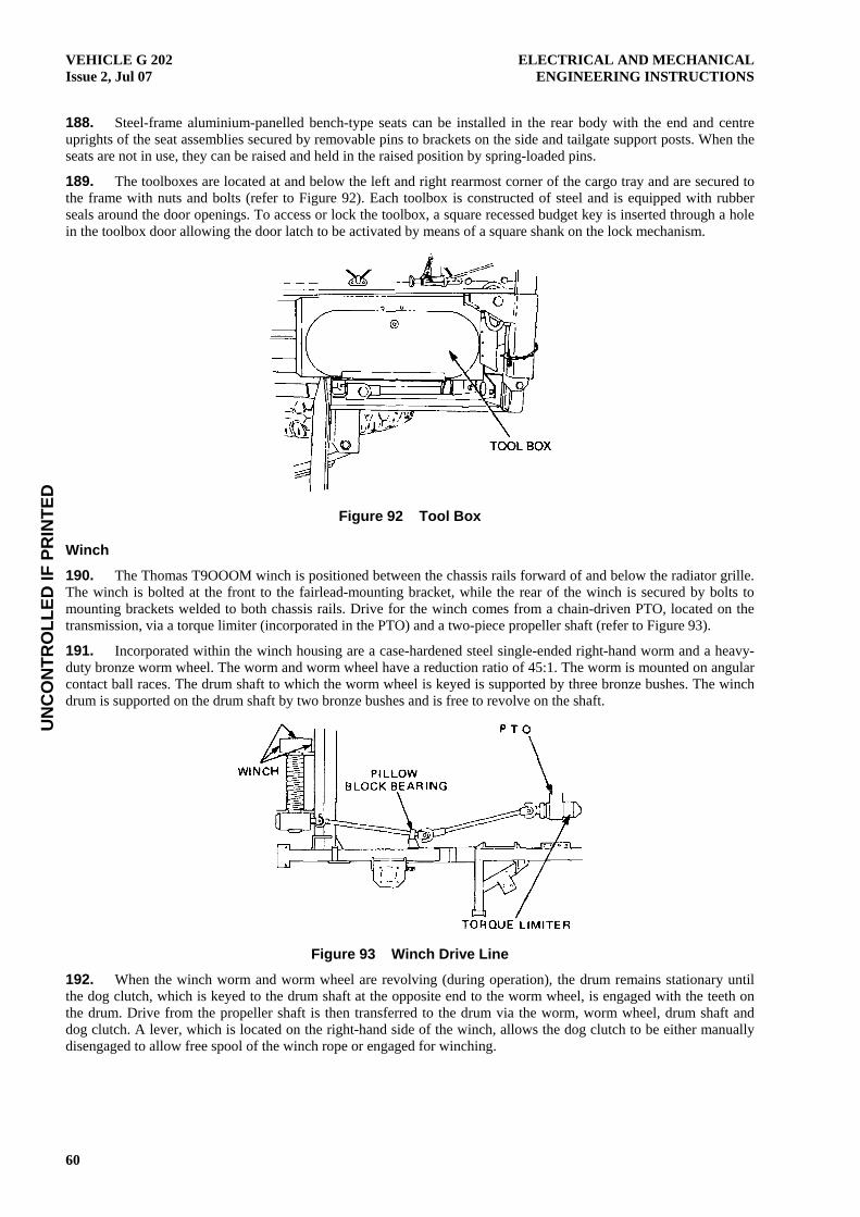
UN
CO
NTR
OLL
ED IF
PR
INTE
D
VEHICLE G 202 Issue 2, Jul 07
ELECTRICAL AND MECHANICAL ENGINEERING INSTRUCTIONS
60
188. Steel-frame aluminium-panelled bench-type seats can be installed in the rear body with the end and centre uprights of the seat assemblies secured by removable pins to brackets on the side and tailgate support posts. When the seats are not in use, they can be raised and held in the raised position by spring-loaded pins.
189. The toolboxes are located at and below the left and right rearmost corner of the cargo tray and are secured to the frame with nuts and bolts (refer to Figure 92). Each toolbox is constructed of steel and is equipped with rubber seals around the door openings. To access or lock the toolbox, a square recessed budget key is inserted through a hole in the toolbox door allowing the door latch to be activated by means of a square shank on the lock mechanism.
Figure 92 Tool Box
Winch
190. The Thomas T9OOOM winch is positioned between the chassis rails forward of and below the radiator grille. The winch is bolted at the front to the fairlead-mounting bracket, while the rear of the winch is secured by bolts to mounting brackets welded to both chassis rails. Drive for the winch comes from a chain-driven PTO, located on the transmission, via a torque limiter (incorporated in the PTO) and a two-piece propeller shaft (refer to Figure 93).
191. Incorporated within the winch housing are a case-hardened steel single-ended right-hand worm and a heavy- duty bronze worm wheel. The worm and worm wheel have a reduction ratio of 45:1. The worm is mounted on angular contact ball races. The drum shaft to which the worm wheel is keyed is supported by three bronze bushes. The winch drum is supported on the drum shaft by two bronze bushes and is free to revolve on the shaft.
Figure 93 Winch Drive Line
192. When the winch worm and worm wheel are revolving (during operation), the drum remains stationary until the dog clutch, which is keyed to the drum shaft at the opposite end to the worm wheel, is engaged with the teeth on the drum. Drive from the propeller shaft is then transferred to the drum via the worm, worm wheel, drum shaft and dog clutch. A lever, which is located on the right-hand side of the winch, allows the dog clutch to be either manually disengaged to allow free spool of the winch rope or engaged for winching.

UN
CO
NTR
OLL
ED IF
PR
INTE
D
ELECTRICAL AND MECHANICAL ENGINEERING INSTRUCTIONS
VEHICLE G 202 Issue 2, Jul 07
61
193. The winch is equipped with a steel wire rope 45 metres long with a diameter of 11 mm. The rope is right-hand ordinary lay with an independent wire rope cord and has a minimum breaking strain of 7 630 kg. A thimble and a Talurit fitting are attached to the free end of the rope. The winch and rope are capable of a line pull of 4 090 kg on the first layer of rope on the winch drum, 3402 kg on the second layer, 2 912 kg on the third layer and 2 545 kg on the fourth layer. However, if these loads are exceeded, the spring-loaded ball-ratchet type torque limiter is activated, separating the driveline from the winch. Once the excess load is removed, the torque limiter resets itself and winching can continue.
194. The fairlead assembly, to which the winch is bolted, provides a means for guiding the wire rope onto the winch by utilising two horizontal and two vertical rollers (refer to Figure 94). The rollers, mounted on removable steel shafts, provide a smooth feed on the wire rope during winching.
Figure 94 Fairlead Assembly
END Distribution List: Vehicle G 12.1 – Code 2 (Maint Level)
(Sponsor: CGSVSPO, Light B Vehicle Section) (Authority: ECO CGSVSPO 120/10)