Electric Rotating Stator Generator with Permanent Magnets ... · Index Terms— PM synchronous...
8
1 Abstract— In the past couple of years, the permanent magnet synchronous generator has been a widely used generator. In spite of its many advantages it also presents some disadvantages. This papers aims to identify them and propose a topology that nullifies this disadvantages. A single phase low voltage generator belonging to an isolated system and providing 20kW to a load modeling a residence is proposed. The presented generator is aimed to work through the kinetic energy extracted from a river current. This research will study and analyze the electromagnetic waveforms and the thermal distribution of the generator through a finite element model. The equations best suited to calculate the power losses in the low speed permanent magnet generator will be identified. Particular attention will be allocated to the identification of the main constraints in the generator sizing. Finally, the dielectric insulation lifetime will be estimated. Index Terms— PM synchronous generator, power losses, finite-element analysis (FEA), thermal analysis , electromagnetic analysis. I. INTRODUCTION he permanent magnet synchronous generator was developed around 1950 [1], and since then, has been the main electrical machine topology in both low velocities applications, such as energy production through alternative sources [2,3], as well as high velocities applications, such as aeronautical industry and flywheels [4,5]. The permanent magnet generator has great benefits such as the absence of brushes, smaller volume and higher efficiency. In this type of generator, the permanent magnets are usually located in the inner part of the machine. However, this topology has some drawbacks, the main one being the occasional ungluing of the magnets due to centrifugal forces originated by the rotational motion of the generator. Another drawback is the fact that this configuration makes the magnetization in loco of the magnets difficult. The study of a new topology in which the magnets are located in the outer part of the machine, that part being the rotor, is proposed in this paper. With this approach the centrifugal force tends to compress the magnets instead of ungluing them, while making this component more easily accessible allowing for an easy maintenance. The proposed generator was designed to operate through the kinetic energy extracted from river currents. The name of the used system is RiverSails, [6], and was developed by the company Tidal Sails. The system consists in a series of extruded aluminum sails, attached to wire ropes strung across the tidal stream. It forms a geometric figure similar to that represented in Fig 1. The generator studied is aimed to be placed in the corners of that system. Fig.1. RiverSails system Based on the river speed the generator was targeted to rotate at 100 rpm at nominal operation. II. MATERIALS THAT FORM THE GENERATOR In this section the materials that form the generator are presented. A. Permanent magnets Permanent magnets were chosen to be made of NdFeB. This choice was based on the fact that this type of magnets presents the higher value of residual magnetic flux density at satisfactory working temperatures [7]. The demagnetization curves of the selected magnets are represented in Fig. 2. Electric Rotating Stator Generator with Permanent Magnets and Fixed Rotor with Concentrated Windings: Analysis and Study on its Magnetic Circuit Gonçalo Miguéis, Student, DEEC/AC Energia and P.J. Costa Branco, LAETA/IDMEC T
Transcript of Electric Rotating Stator Generator with Permanent Magnets ... · Index Terms— PM synchronous...

1
Abstract— In the past couple of years, the
permanent magnet synchronous generator has been a widely used generator. In spite of its many advantages
it also presents some disadvantages. This papers aims to identify them and propose a topology that nullifies
this disadvantages. A single phase low voltage generator belonging to an
isolated system and providing 20kW to a load modeling
a residence is proposed. The presented generator is aimed to work through the kinetic energy extracted
from a river current.
This research will study and analyze the
electromagnetic waveforms and the thermal distribution of the generator through a finite element
model. The equations best suited to calculate the power losses in the low speed permanent magnet
generator will be identified. Particular attention will be allocated to the identification of the main constraints in the generator sizing.
Finally, the dielectric insulation lifetime will be estimated.
Index Terms— PM synchronous generator, power
losses, finite-element analysis (FEA), thermal analysis , electromagnetic analysis.
I. INTRODUCTION
he permanent magnet synchronous generator was
developed around 1950 [1], and since then, has
been the main electrical machine topology in both low
velocities applications, such as energy production
through alternative sources [2,3], as well as high
velocities applications, such as aeronautical industry
and flywheels [4,5]. The permanent magnet generator
has great benefits such as the absence of brushes,
smaller volume and higher efficiency.
In this type of generator, the permanent magnets are
usually located in the inner part of the machine.
However, this topology has some drawbacks, the main
one being the occasional ungluing of the magnets due
to centrifugal forces originated by the rotational motion
of the generator. Another drawback is the fact that this
configuration makes the magnetization in loco of the
magnets difficult.
The study of a new topology in which the magnets
are located in the outer part of the machine, that part
being the rotor, is proposed in this paper. With this
approach the centrifugal force tends to compress the
magnets instead of ungluing them, while making this
component more easily accessible allowing for an easy
maintenance.
The proposed generator was designed to operate
through the kinetic energy extracted from river
currents. The name of the used system is RiverSails,
[6], and was developed by the company Tidal Sails. The
system consists in a series of extruded aluminum sails,
attached to wire ropes strung across the tidal stream.
It forms a geometric figure similar to that represented
in Fig 1. The generator studied is aimed to be placed in
the corners of that system.
Fig.1. RiverSails system
Based on the river speed the generator was targeted
to rotate at 100 rpm at nominal operation.
II. MATERIALS THAT FORM THE GENERATOR
In this section the materials that form the generator
are presented.
A. Permanent magnets
Permanent magnets were chosen to be made of
NdFeB. This choice was based on the fact that this type
of magnets presents the higher value of residual
magnetic flux density at satisfactory working
temperatures [7]. The demagnetization curves of the
selected magnets are represented in Fig. 2.
Electric Rotating Stator Generator with
Permanent Magnets and Fixed Rotor with Concentrated Windings: Analysis and Study
on its Magnetic Circuit
Gonçalo Miguéis, Student, DEEC/AC Energia and P.J. Costa Branco, LAETA/IDMEC
T

2
Fig.2. Demagnetization curves of the permanent magnets
B. Soft magnetic material
Due to its low cost, a non-oriented type of magnetic
material was chosen. Its magnetization curve is
illustrated in Fig. 3. This material is constituted by
laminated and dielectrically insulated sheets.
Fig.3. BH curve of the soft magnetic material
C. Shaft
Steel was selected to form the shaft of the generator .
This material was chosen due to its strong mechanical
characteristics associated with the fact that it is
nonmagnetic and so does not influence the magnetic
circuit of the generator.
D. Conductors
The conductors are made of copper. This is a common
choice in the construction of electric machines due to
relation between its price and electrical conductivity.
III. POWER LOSSES CALCULATION
In addition to reducing the efficiency, the power
losses also have the adverse effect of the heating the
electrical machines. The methods used to calculate
these losses are presented in this section.
A. Copper losses
The copper losses in the generator windings, 𝑃𝑐𝑢 ,
were calculated through equation (1). This equation is
only valid for sinusoidal systems. As it is not the case,
the total copper losses are the some of the equation (1)
applied to all the harmonics of the generator current.
The parameter 𝑟𝑐𝑢 is the winding resistance and 𝐼𝐼𝑛 is
the rms value of the generator current. 𝑃𝑐𝑢 = 𝑟𝑐𝑢 𝐼𝐼𝑛
2 (1)
B. Ferromagnetic materials losses
Due to low velocity of the generator and consequent
low electric frequency of its currents, it is sometimes
difficult to estimate the Steinmetz coefficients from the
manufacturer data. Therefore, the Steinmetz equation,
regardless of being one of the most used in that matter,
is not used in this paper to estimate losses in the
ferromagnetic materials.
The selected equation is (2). The symbol 𝐽𝐹
represents the rms value of the current density of the
Foucault currents and 𝜎 is the electrical conductivity of
the material where the losses are calculated.
𝑃𝐹 = ∫𝐽𝐹
2
𝜎𝑉
𝑑𝑉 (2)
The ferromagnetic materials include the permanent
magnets and the soft ferromagnetic material. Since the
soft magnetic material is formed by a series of
insulated electrical sheets, its electrical conductivity
differs from that of a solid block. The equation (4)
allows the estimation of the electrical conductivity of the laminated material, [8]. The symbol 𝜎𝑒𝑞 is the
equivalent electrical conductivity of the laminated
material, 𝜎𝑀 is the electrical conductivity of the non-
laminated material, 𝑥 𝑙𝑎𝑚 is the number of laminations
that the material has and can be calculated through
the equation (3). In this equation 𝐷 is the depth of the
generator and 𝜀𝑙𝑎𝑚 is the thickness of one sheet.
𝑥𝑙𝑎𝑚 =𝐷
𝜀𝑙𝑎𝑚
(3)
𝜎𝑒𝑞 =𝜎𝑀
𝑥𝑙𝑎𝑚2 (4)
IV. ELECTRICAL GENERATOR, POWER CONVERTER AND
LOAD
The electrical generator geometry as well as the
power converter and load, which forms the isolated
system in study, is presented in this section.

3
A. PM synchronous generator
Fig.4. Magnetization direction of the permanent magnets and
winding direction of the electrical conductors
Fig. 5 illustrates a 3D image of the permanent
magnet generator. Its dimensions are synthetized in
Tab. I.
Fig. 5 Electrical generator proposed geometry
TABLE I GEOMETRIC CHARACTERISTICS OF THE ELECTRICAL GENERATOR
Parameter Value
Stator diameter [mm] 486
Air gap [mm] 1
Permanent magnets
height [mm]
6
Rotor diameter [mm] 540
Depth [mm] 480
Number of pole pairs 10
A single phase low voltage generator is proposed in
this paper. This implies that the maximum value of its
rms voltage has to be lower than 1kV, [9].
In Fig. 4 the directions of magnetization of the
permanent magnets as well as the winding direction of
the conductors are presented. Due to difficulties in
representation it is only pictured a winding per pole in
Fig. 4. However, the generator has 𝑁𝑠 windings in
series per slot. In order to reduce copper losses there
are also 𝑁𝑃 of this circuits in parallel.
B. Power converter
The use of a power converter is necessary due to the
voltage amplitude and electric frequency difference
between the generator and load. An AC/DC/AC
converter is proposed and can be seen in Fig. 6. This
converter consists of a single-phase rectifier followed
by a capacitor (DC link) and a three-phase inverter.
Fig. 6. Isolated electrical system with focus on power converter
C. Electric load
Fig. 7. Isolated electrical system with focus on electrical load
The electrical load is intended to model an average
residence. For this reason, it is constituted by a three
phase resistance in series with an inductor with a
power factor of 0.86. It is also intended that the
generator provides 20 kW of active power to the load.
The electrical load is represented Fig. 7.
𝐿𝑜
𝑎𝑑
Load Rectifier Inverter
𝐺𝑀𝑃

4
V. REQUIREMENTS IN SIZING PM GENERATOR
The sizing of the proposed generator implies the
fulfilment of certain conditions, both electromagnetic
and thermal. This section lists these constraints.
A. Electromagnetic constraints
The first of these constraints are expressed in
equations (5) and (6) and require that the magnetic flux
density in soft magnetic material in the rotor, 𝐵𝐼𝑑𝑡 , and
the stator, 𝐵𝐼𝑑𝑧, of the generator are less than the value
that forms a “knee” in the magnetization curve of this material, 𝐵𝐽 . Its conditions assure the non-saturation
of the material. 𝐵𝐼𝑑𝑡 ≤ 𝐵𝐽 (5)
𝐵𝐼𝑑𝑧 ≤ 𝐵𝐽 (6)
The following of these constraints are depicted in
equation (7) and determines the maximum number of
windings in a slot, 𝑁𝑀𝑎𝑥, assuring that the area of the
simulated number of windings is less than the area of
the slot in which they will be allocated. The variable
𝐴𝑟𝑒 𝑎𝐶𝑜𝑛𝑑 is the cross section of a conductor, 2.09 𝜇 𝑚2,
𝐴𝑟𝑒 𝑎𝑆𝑙𝑜𝑡 is the area of the slot, and 𝐾𝑐𝑢 is the window
the utilization factor and represents the fraction of the
core window area that is filled by copper, its usual
values vary between 0.3 and 0.7 [10]. The selected value
was 0.5.
𝑁𝑆 ∙ 𝑁𝑃 ≤𝐾𝑐𝑢 𝐴𝑟𝑒 𝑎𝑆𝑙𝑜𝑡
𝐴𝑟𝑒𝑎𝐶𝑜𝑛𝑑
= 𝑁𝑀𝑎𝑥 (7)
The following constraints, eq. (8) and eq. (9), assure
that the generator doesn’t exceed a maximum voltage
limit, eq. (8), and that the active power delivered to the load, 𝑃𝐶 , is the desired, eq. (9). 𝑉𝐺𝑒 𝑟𝑀𝑎𝑥
is the maximum
value of the voltage at the generator terminals. This
voltage value was imposed in order to avoid the use of
𝑑𝑉/𝑑𝑡 filters, [11]. 𝑉𝐺𝑒 𝑟𝑀𝑎𝑥
< 1 kV (8)
𝑃𝐶 = 20 kW (9)
The last constraint is related to the ability of the
permanent magnets to keep its magnetization
competence. For this it is required that the flux density in the magnet, 𝐵𝑀𝑎𝑔 , is more than that forming the
“knee” in Fig. 2, [12], in this case 0. 35 T. 𝐵𝑀𝑎𝑔 > 0.35 T (10)
If the constraints (7) to (10) are not met, the
parameter 𝑁𝑆 which represents the number of windings
in series per slot, should be decreased. If the
constraints (5) and (6) are not met the geometry of the
generator should be rearranged.
B. Thermal requirements
Once again the first thermal requirement is related
to the competence of the permanent magnets to keep
its magnetization ability. For this it is required that
the temperature in the magnets, 𝑇𝑀𝑎𝑔 , is less than his
maximum operation temperature value, [12]. For the
chosen permanent magnets this temperature is 150℃ ,
but in order to assure a safety margin it was decided
that the temperature in the magnets must be less than
135℃ . 𝑇𝑀𝑎𝑔 < 135℃ (11)
Another temperature limit that has to be respected
concerns the conductor’s insulation, 𝑇𝐶𝑜𝑛𝑑 . For the
present machine, an insulator with a maximum
operating temperature of 180℃ was chosen. 𝑇𝐶𝑜𝑛𝑑 < 180℃ (12)
If the constraints (11) to (12) are not met, the
parameter 𝑁𝑃 which represents the number of circuits
in parallel per slot, should be increased.
VI. ELECTROMAGNETIC WAVEFORMS IN NOMINAL
OPERATION MODE
The generator topology presented in chapter IV was
simulated in an electromagnetic finite element model
from a 2D geometry. The variables 𝑁𝑆, 𝑁𝑃 and 𝐷 were
changed in order to fulfil all the constraints mentioned
in the previous chapter.
A. Electromagnetic waveforms in nominal operation mode
Fig. 8 shows the magnetic flux density distribution.
It can be seen in this figure that the constraints (5) and
(6) are met.
Fig. 8. magnetic flux density distribution
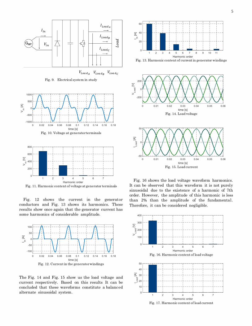
Fig. 9 illustrates the isolated system in study. In this
figure, the voltage and currents presented in the course
of this paper are schematized.
Fig. 10 shows the voltage at the generator terminals
and Fig. 11 shows its harmonics. In Fig. 11 can be seen
that the generator voltage has a 3rd harmonic of high
amplitude, however it is not a requirement that the
generator waveform be close to sinusoidal. Only the
load voltage and current need to meet this criterion. We
can see in Fig. 10 that the constraint (8) is met.
𝐵 [T]
5
Fig. 9. Electrical system in study
Fig. 10. Voltage at generator terminals
Fig. 11. Harmonic content of voltage at generator terminals
Fig. 12 shows the current in the generator
conductors and Fig. 13 shows its harmonics. These
results show once again that the generator current has
some harmonics of considerable amplitude.
Fig. 12. Current in the generator windings
The Fig. 14 and Fig. 15 show us the load voltage and
current respectively. Based on this results It can be
concluded that these waveforms constitute a balanced
alternate sinusoidal system.
Fig. 13. Harmonic content of current in generator windings
Fig. 14. Load voltage
Fig. 15. Load current
Fig. 16 shows the load voltage waveform harmonics.
It can be observed that this waveform it is not purely
sinusoidal due to the existence of a harmonic of 7th
order. However, the amplitude of this harmonic is less
than 2% than the amplitude of the fundamental.
Therefore, it can be considered negligible.
Fig. 16. Harmonic content of load voltage
Fig. 17. Harmonic content of load current
𝐿𝑜
𝑎𝑑
𝐼𝐿𝑜𝑎𝑑𝐴
𝐼𝐿𝑜𝑎𝑑𝐵
𝐼𝐿𝑜𝑎𝑑𝐶
𝑉𝐿𝑜𝑎 𝑑𝐴 𝑉𝐿𝑜𝑎 𝑑𝐶
𝑉𝐿𝑜𝑎 𝑑𝐵
𝐼𝐼𝑛
𝑉𝐼𝑛

6
On the other hand, we can see in Fig. 17 that the load
current waveform is purely sinusoidal.
Fig. 18 shows the magnetic flux density in the
permanent magnets during an electrical cycle. This
waveform is not purely sinusoidal due to effects of the
magnetic flux density produced by the current that
circulates in the generators conductors, according to
Lenz law. Analyzing Fig. 18 it can be concluded that
constraint (10) is also met.
Fig. 18. Magnetic flux density in the permanent magnets
VII. THERMAL FINITE ELEMENT ANALYSIS
With the aim of checking whether the generator
materials have a temperature value above its
maximum operating temperature, the thermal
behavior of the generator was simulated with the aid
of a finite element program.
A. 2D finite element thermal model
The temperatures in the materials of the electrical
generator are dependent on the surrounding external
temperature and on the heat dissipation created by the
power losses. The permanent magnet generator
operates at low electric frequency, 𝑓, of 50
3 Hz according
to equation (13) where 𝑛 is the velocity, 100 rpm and 𝑝
is the number of pole pairs, 10. Since the electric
frequency has a low value and since the power losses in
the soft magnetic material are proportional to its
frequency, we conclude that these losses can be
considered negligible.
𝑓 =𝑛 𝑝
60 (13)
On the other hand, the permanent magnet, 𝑃𝑀𝑃 ,
and copper losses, 𝑃𝐶𝑢 , have a high impact on the
generator temperature and are presented in Tab. II.
The copper losses are the most significant ones,
accounting for approximately 80% of the generator
losses
TABLE II LOSSES IN THE PERMANENT MAGNET GENERATOR
Parameter Value 𝑃𝐶𝑢 [W] 497
𝑃𝑀𝑃 [W] 132
Based on these power losses values, the generator
temperature distribution illustrated in Fig. 19 was
obtained.
Fig. 19. Thermal distribution of generator simulated in 2D finite
element model
Fig. 19 shows that the constraints (11) and (12) are
met since the temperature on the magnets is 134℃ and
the temperature on the copper conductors is 155℃ .
Since Fig. 19 was obtained through a 2D thermal finite
element model the heat distribution was only
considered radially due to software limitations.
B. 3D finite element thermal model
In spite of Fig. 19 presenting the worst possible
scenario of the machines operation conditions, this is
not the thermal distribution that it is obtained in
nominal operation conditions. In order to accurately
obtain this distribution, the same geometry with the
same power losses values was simulated, on a 3D
thermal finite element model. The thermal distribution
obtained by this model is illustrated in Fig. 20.
Fig. 20. Thermal distribution of generator simulated in 3D finite
element model
It can be seen in Fig. 19 that the heat distribution
now occurs radially and through the generator shaft.
In this model the temperature on the magnets is 8℃
𝑇 [℃]
𝑇 [℃]

7
less and the temperature on the copper conductors is
12℃ less than the temperature present in Fig. 19.
VIII. UNBALANCED OPERATION LOAD
The performance of the generator in the event of loss
of one phase of the three-phase load will be analyzed in
this section. In this event, the load voltage and the load
current have the waveforms represented in Fig. 21 and
Fig. 22 respectively. It can be verified that the phase
differences between currents or voltages becomes 90º
instead of the 120º shown in Fig. 14 and Fig. 15.
Fig. 21. Load voltage with loss of one of the load phases
Fig. 22. Load current with loss of one of the load phases
It can be concluded that the load current waveform
is almost the same as the one in balanced load
operation. On the other hand, the voltage waveform
has a slight distortion, in addition to having a rms
value of 221 V which corresponds to a reduction of 4%
comparing with the balanced load operation.
Regarding the generator’s voltage waveform, it can
be concluded that this waveform, Fig. 23, is similar to
that verified in balanced load operation.
Fig. 23. Generator’s voltage with loss of one of the load phases
On the other hand, due to the loss of one of the load
phases the equivalent load impedance has a lower
value than that in the balanced load operation, leading
to a 40% lower rms generator’s current, Fig. 24.
Fig. 24. Generator’s current with loss of one of the load phases
Due to this low rms generator’s current, the
generator’s copper losses drop 64% . The permanent
magnet losses also suffer a reduction of 38% comparing
to the balanced load operation.
Since the generator’s power losses in unbalanced
load operation has lower values that the ones in
balanced load operation, it can be implied that the
generator material’s temperatures will be also lower in
these operation conditions.
Therefore, it can be concluded that the generator
supports the loss of one of the load phase without
damaging its lifetime expectancy.
IX. DIELECTRIC INSULATION LIFETIME ESTIMATION
The electrical insulation material used to isolate
between wires has a certain lifetime duration. This
lifetime can be defined as the period of time since the
completion of its fabrication until the point where its
required performance can no longer be achieved [13].
To determine the insulation lifetime, 𝐿𝑖𝑠 equation
(14) [14], was used. In this equation 𝑇𝑖𝑠 is the
temperature in the dielectric insulation, 𝑘𝑖𝑠 is the
Stefan-Boltzmann constant, 𝜗𝑖𝑠 is the activation energy
and 𝐵𝑖𝑠 is a constant associated with the material.
𝐿𝑖𝑠 = 𝐵𝑖𝑠 𝑒𝜗𝑖𝑠
𝑘𝑖𝑠 𝑇𝑖𝑠 (14)
The material chosen to perform dielectric insulation
in the copper conductors was polyester epoxy. This
material has a maximum operation temperature of
180℃ and can withstand the 155℃ verified in the worst
case scenario. The values of the parameters present in
Eq.(14) are in Tab. III, [13,15], and the insulation
lifetime in function of the temperature is illustrated in
Fig.25.
TABLE III
VALUES OF THE PARAMETERS IN EQ. (14)
Parameter Value
𝐵𝑖𝑠 [h] 8.97
𝜗𝑖𝑠 [eV] 1.38
𝑘𝑖𝑠 [ μ eV/K] 86.17
If the permanent magnet generator is always
operating at nominal condition, the insulation lifetime
is 144 340 ℎ (approximately 16 years).

8
Fig. 25. Insulation lifetime of dielectric insulator
X. CONCLUSIONS
During this paper, a permanent magnet topology
that prevents the ungluing of the permanent magnets
was studied. For this, a topology where the stator is
located in the inner part of the machine and the rotor
is located in his outer part was proposed.
The permanent magnet generator was inserted in an
isolated system composed by the generator, a power
converter and an electrical load modeling a residential
load. The generator was dimensioned, to have 10 pole
pairs and deliver 20 kW of active power to the load.
In this paper it was concluded that the losses in the
soft magnetic material are negligible at low frequency,
and that the Steinmetz equation is not a good approach
to calculate power losses due to lack of data from the
material manufactures regarding losses at low electric
frequencies. An alternative approach to calculate these
same power losses is presented, as well as an
alternative approach to calculate electrical
conductivity of the soft magnetic material due to its
constitution of laminated sheets.
In section V the electromagnetic and thermal
constraints related to the sizing of the generator were
presented.
It was concluded in this paper, that although the
voltage and current waveforms at the generator
terminals have some harmonic content, with the
application of the power converter and its filters, the
voltage and current waveforms delivered to the load
have almost no harmonic content.
Regarding the thermal analysis, it was concluded
that the thermal finite element 2D model is not as
accurate as the thermal finite element 3D model since
the first only considers heat dissipation radially.
In the following section it was concluded that the
generator supports the loss of one of the load phases
without damaging its lifetime expectancy.
Finally, in section VIII, the lifetime of the insulating
material between the wires of the winding was
estimated. This lifetime was estimated assuming the
generator operation at nominal conditions. It was
concluded that the insulation lifetime is approximately
16 years.
REFERENCES
[1] B. Marques, “Virtual Prototyping of a Brushless Permanent
Magnet AC Motor - Electromagnetic and Thermal Design using
CAD”, M.S. thesis, Dept. Elect. Eng. and Comput. Sci., IST, Lisbon, Portugal, 2012.
[2] N. Madani, “Design of a Permanent Magnet Synchronous
Generator for a Vertical Axis Wind Turbine”, M.S. thesis, Dept.
Elect. Eng., KTH, Stockholm, Sweden, 2011
[3] T. Reigstad, “Direct Driven Permanent Magnet Synchronous Generators with Diode Rectifiers for Use in Offshore Wind
Turbines”, M.S. thesis, Dept. Elect. Power. Eng., NTNU,
Trondheim, Norway, 2007.
[4] J. Cardoso, “Análise de soluções para geradores eléctricos
integrados em turbinas de aeronaves”, M.S. thesis, Dept. Elect.
Eng. and Comput. Sci., IST, Lisbon, Portugal, 2014. [5] M. Marques, “Design and Control of an Electrical Machine for
Flywheel EnergyStorage System”, M.S. thesis, Dept. Elect. Eng.
and Comput. Sci., IST, Lisbon, Portugal, 2008.
[6] Tidal Sails. (2014, Oct. 2). Tidal Sails [online]. Available:
http://tidalsails.com/about-us [May 6, 2016]. [7] Permanent Magnet Selection and Design Handbook, 1st ed.,
Magcraft Co, Richmond, Virgínia, USA, 2007.
[8] J. Kim, “A equivalent finite element of lamination for design of
electromagnetic engine valve actuator”, J. of Magnetics, vol. 4,
no. 11, pp. 151-155, Aug., 2006.
[9] J. Pyrhonen, T. Jokinen and V. Hrabovcová, Design of Rotating Electrical Machines, 2nd ed. New Delhi, India, Wiley, 2014.
[10] M. Kazimierczuk and H. Sekiya, “Design of AC Resonant
Inductors Using Area Product Method”, ECCE Energy
Conversion Congress and Exposition, San Jose, CA, USA, 2009
[11] Motor Book, Grundfos Co, Bjerringbro, Denmark, 2004, pp. 174.
[12] Magnet Guide & Tutorial, Alliance LLC Co, Valparaiso, Chile, 2013.
[13] E. Brancato, “Estimation of Lifetime Expectancies of Motors”,
IEEE Electr. Insul. Mag., vol. 8, no. 3, pp. 5 - 13, August, 2002
[14] T. Dakin, “Electrical Insulation Deterioration Treated as a
Chemical Rate Phenomenon”, IEEE Trans. Commun., vol. 67,
no. 1, pp. 113 – 115, June, 2009 [15] C. Han, “Lifetime Evaluation of Class E Electrical Insulation for
Small Induction Motors”, IEEE Electr. Insul. Mag., vol. 27, no.
3, pp. 14, June, 2011.