Electric Power System Appendix
11
APPENDIX COMPLEX, REAL AND REACTIVE POWER 3 = 3 + 3 for any balanced or unbalanced load. 3 = 3 + 3 =3 ¡ 1 + 1 ¢ for a balanced load and source. 3 = √ 3 | − || | ∠ ( − ) valid only for a balanced three-phase source or load. One defines as the voltage angle and as the current angle. 3 =3 | − || | ∠ ( − ) valid only for a balanced three-phase source or load. One defines as the voltage angle and as the current angle. || = p 2 + 2 This is true for only sinusoidal steady-state systems. = ||× = √ 2 + 2 = cos ( − ) = | | 2 = ||× = p 1 − 2 = | | 2 POWER FACTOR CORRECTION = ∙r 1− 2 2 − q 1− 2 2 ¸ BALANCED SET OF THREE-PHASE VOLTAGES AND THE A-B-C PHASE SEQUENCE 0 120 cn V V an V V 0 120 bn V 0 0 0 3 30 3 90 3 150 ab an bc bn ca cn V V V V V V − − phase sequence and a balanced set of voltages 1
-
Upload
eduardo-steffens -
Category
Documents
-
view
1 -
download
0
description
A brief Electric Power System Appendix, contains a lot of useful formulas
Transcript of Electric Power System Appendix
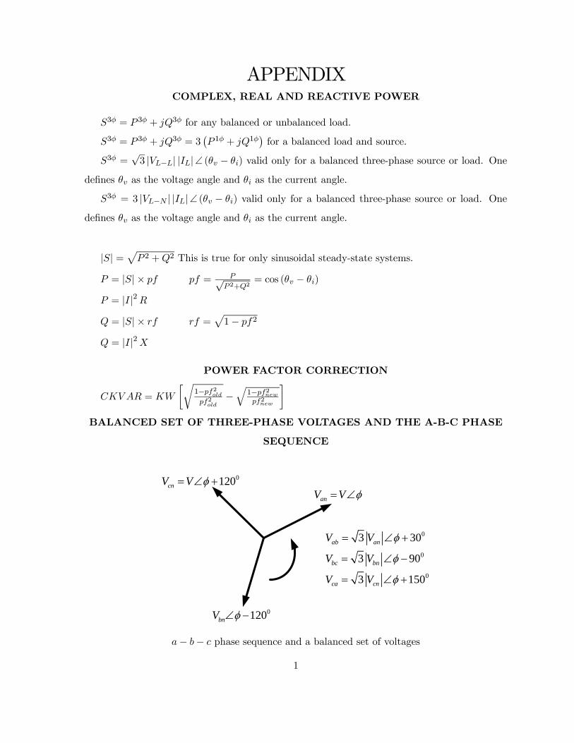
APPENDIXCOMPLEX, REAL AND REACTIVE POWER
3 = 3 + 3 for any balanced or unbalanced load.
3 = 3 + 3 = 3¡ 1 + 1
¢for a balanced load and source.
3 =√3 |−| ||∠ ( − ) valid only for a balanced three-phase source or load. One
defines as the voltage angle and as the current angle.
3 = 3 |− | ||∠ ( − ) valid only for a balanced three-phase source or load. One
defines as the voltage angle and as the current angle.
|| =p 2 +2 This is true for only sinusoidal steady-state systems.
= || × = √ 2+2
= cos ( − )
= ||2 = || × =
p1− 2
= ||2
POWER FACTOR CORRECTION
=
∙r1−2
2
−q
1−22
¸BALANCED SET OF THREE-PHASE VOLTAGES AND THE A-B-C PHASE
SEQUENCE
0120cnV V anV V
0120bnV
0
0
0
3 30
3 90
3 150
ab an
bc bn
ca cn
V V
V V
V V
− − phase sequence and a balanced set of voltages
1
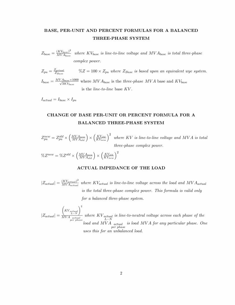
BASE, PER-UNIT AND PERCENT FORMULAS FOR A BALANCED
THREE-PHASE SYSTEM
=()
2
where is line-to-line voltage and is total three-phase
complex power.
=
% = 100× where is based upon an equivalent wye system.
=×1000√
3where is the three-phase base and
is the line-to-line base .
= ×
CHANGE OF BASE PER-UNIT OR PERCENT FORMULA FOR A
BALANCED THREE-PHASE SYSTEM
=
׳
´×³
´2where is line-to-line voltage and is total
three-phase complex power.
% = % ׳
´×³
´2ACTUAL IMPEDANCE OF THE LOAD
|| = ()2
where is line-to-line voltage across the load and
is the total three-phase complex power. This formula is valid only
for a balanced three-phase system.
|| =
−
2
where −
is line-to-neutral voltage across each phase of the
load and
is load for any particular phase. One
uses this for an unbalanced load.
2

MILLMAN’S THEOREM
1 1V 2 2V 3 3V 4 4V
1Z 2Z 3Z 4Z
V
Z
N NV
NZ
e∠ =1∠1
³11
´+ 2∠2
³12
´+ 3∠3
³13
´+ 4∠4
³14
´+ ∠
³1
´11+ 1
2+ 1
3+ 1
4+ 1
e =1
11+ 1
2+ 1
3+ 1
4+ 1
DELTA-WYE TRANSFORMATION
1 =
+ + 2 =
+ + 3 =
+ +
=12 + 23 + 31
2 =
12 + 23 + 31
3 =
12 + 23 + 31
1
AZ
BZ
CZ
1Z 2Z
3Z
a b
c
c
3

THE GENERAL TRANSMISSION LINE EQUATIONS
The exact transmission line equations are given by:
() = cosh () + sinh () (1)
() = cosh () +
0sinh () (2)
= cosh () + sinh () (3)
= cosh () +
0sinh () (4)
= cosh ()− sinh () (5)
= cosh ()−
0sinh () (6)
where = − . Distance is defined as the distance measured from the receiving end of
the transmission line to the sending end of the transmission line. So when = 0, (0) =
and (0) = . Likewise, when = , () = and () = . One can also rewrite the
characteristic impedance as
=
s(+ )
(+ ) (7)
=
r
(8)
where
= = (+ ) ≡ Ω
and ≡
(9)
= = (+ ) ≡ Ω−1
and ≡
(10)
One can also write the constant as
=p(+ ) (+ ) =
√ (11)
4

Substitute (8) and (11) into (3) through (6) to get
= cosh³√
´+
r
sinh
³√
´(12)
= cosh³√
´+
sinh³√
´
√
(13)
= cosh³√
´+
q
sinh³√
´
(14)
= cosh³√
´+
sinh³√
´
√
(15)
= cosh³√
´−
r
sinh
³√
´(16)
= cosh³√
´−
sinh³√
´
√
(17)
= cosh³√
´− q
sinh³√
´
(18)
= cosh³√
´−
sinh³√
´
√
(19)
The ABCD parameters of a long transmission line are given by:
= = cosh³√
´
= sinh
³√
´√
= sinh
³√
´√
For finding the voltage and current anywhere on the line one can rewrite (1) as
() = cosh () + sinh () (20)
= cosh
µ√
¶+
µ
¶ sinh³√
´√
(21)
5

Likewise, (2) can be written as
() = cosh () +
0sinh () (22)
= cosh
µ√
¶+
µ
¶ sinh³√
´√
(23)
Therefore, (21) and (23) can be used to compute the voltage and current anywhere on the line
in the range 0 ≤ ≤ .
The short-line transmission line equations are given by
⎡⎣
⎤⎦ =⎡⎣ 1
0 1
⎤⎦⎡⎣
⎤⎦⎡⎣
⎤⎦ =⎡⎣ 1 −0 1
⎤⎦⎡⎣
⎤⎦and the equivalent circuit is given by
LOADsV
rIsI
rV
R j L
and = + .
6

The ABCD parameters of a short transmission line are given by:
= = 1
=
= 0
The medium-line transmission line equations for the nominal T-Network are:
⎡⎣
⎤⎦ =⎡⎣ 1 +
2¡1 +
4
¢ 1 +
2
⎤⎦⎡⎣
⎤⎦⎡⎣
⎤⎦ =⎡⎣ 1 +
2− ¡1 +
4
¢− 1 +
2
⎤⎦⎡⎣
⎤⎦and the equivalent circuit is given by
LOADsV
rIsI
rV
2
R
2
j L
Y
2
j L2
R
2
Z2
Z
where = + and = .
The ABCD parameters of a medium transmission line for the nominal Network are given
7
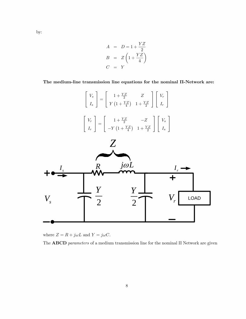
by:
= = 1 +
2
=
µ1 +
4
¶ =
The medium-line transmission line equations for the nominal Π-Network are:
⎡⎣
⎤⎦ =⎡⎣ 1 +
2
¡1 +
4
¢1 +
2
⎤⎦⎡⎣
⎤⎦⎡⎣
⎤⎦ =⎡⎣ 1 +
2−
− ¡1 + 4
¢1 +
2
⎤⎦⎡⎣
⎤⎦
LOADsV
rIsI
rV
R j L
2
Y
2
Y
Z
where = + and = .
The ABCD parameters of a medium transmission line for the nominal Π Network are given
8

by:
= = 1 +
2
=
=
µ1 +
4
The relationship which must exist among the ABCD parameters regardless of whether the
line is long, medium or short is the following:
− = 1
9

NONSINUSOIDAL CURRENTS AND VOLTAGES
Displacement Factor
= cos ( − )
True Power Factor
=
00 +
X=1
cos ( − )vuut X=0
2
vuut X=0
2
Apparent Power
=
vuut X=0
2
vuut X=0
2
Real power
= 00 +
X=1
cos ( − )
Budeanu Reactive Power
=
X=1
sin ( − )
Budeanu Distortion Power
=
q2 − ( 2 +2)
10

SYMMETRICAL COMPONENTS
Let , , and be a set of unbalanced three-phase voltages as shown in Figure A.
Positive-Sequence Voltages
Negative-Sequence Voltages Zero-Sequence Voltages
anVbnV
cnV
1anV
1bnV
1cnV
2anV
2bnV
2cnV
0anV
0bnV
0cnVn
Figure A
= 0 + 1 + 2
= 0 + 21 + 2
= 0 + 1 + 22
0 = + +
3
1 = + + 2
3
2 = + 2 +
3
0 = 0 = 0
|1| = |1| = |1|
|2| = |2| = |2|
where = 1∠1200.
11