
Electric Power Book 1
313
Electric Current Theory What is Electrical Current? An atom consists of central nucleus having positively charged protons surrounded by negatively charged electron in motion. Total no of positively charged proton in nucleus and negativity charged electrons in nucleus are equal. Hence net charge of an atom is zero means atom as a whole is neutral. Each electrons has negative charge of - 1.602 X 10 - 19 Coulombs Each protons has positive charge of 1.602 X 10 - 19 Coulombs Theory of Electrical Current Theory of Electrical Potential Single Phase Power Three Phase Power Complex Power Electrical Fuse Miniature Circuit Breaker
-
Upload
iskeel-sadiq -
Category
Documents
-
view
115 -
download
0
Transcript of Electric Power Book 1

Electric Current Theory
What is Electrical Current?
An atom consists of central nucleus having positively charged protons surrounded by negatively charged electron in motion. Total no of positively charged proton in nucleus and negativity charged electrons in nucleus are equal. Hence net charge of an atom is zero means atom as a whole is neutral.
Each electrons has negative charge of - 1.602 X 10 - 19 Coulombs
Each protons has positive charge of 1.602 X 10 - 19 Coulombs
Theory of Electrical CurrentTheory of Electrical PotentialSingle Phase PowerThree Phase PowerComplex PowerElectrical FuseMiniature Circuit Breaker
The electrons revolve around the nucleus in various orbits. The electron in outer most orbit is most loosely bonded with nucleus as because the attractive force between this negative electron and the positive nucleus is least at the outer most orbit. Hence very small force is sufficient to

detach the outer most electrons from its parent atom. This atom with short of electron becomes positively charged. This electrons moves in the conductor body in a random manner as free electrons. That means it comes out from atom and moving here and there in the body, again if it finds any atom nearby where there is short of electron then this free electron enters into vacant shell of this atom again after sometime if any collision takes place between this valence electron with other free electrons, it leaves this shell and again starts moving in random manner until it gets another vacant shell. As the electrons or negative charge carriers move freely here and there in a substance body and make atoms positively charged and neutral alternatively in random manner, we can assume that positive charge carriers move in same relative random motion.
Drift Velocity
Drift velocity is associated with random velocities of free charge carriers in a substance.
Definition of drift velocity
The average velocity Vd(r) of charge carriers over a differential velocity of given location r is called the drift velocity at this location
Vd = (1/N)∑Vi
Explanation of drift velocity
Drift velocity can be compared with movement of crowds. In crowd consider people are moving here and there with different direction and velocities in random manner. For drift velocity we have to consider a relatively small space inside which we have to examine what is the average velocity of all randomly moving particles inside that space. For calculating drift velocity at your location when you are in a crowd, we consider the your movement at that location in the crowd and movement of other few people surround you. The average velocity of you and those people in a particular direction will be the drift velocity of that location. In other part of the crowd people may have different velocities so the drift velocities of different locations in the crowd may be different.
Current Density

Think about the movements of charge carriers in a conductor. They have the same kind of random velocity as we explain in the crowd in last paragraph. So the the drift velocity of any location in a conductor can be calculated. If we consider a unit volume of space in the conductor where concentration of charge carriers is ′n′ number and ′q′ is the charge of each similar charge carrier, the rate of charge transferring to a particular direction through the surface, (particular to the direction of drift velocity) of the said space is nothing but product of concentration of charge carriers ′n′ of that space, charge per carrier ′q′ and the drift velocity Vd of that location to the said direction. The rate of charge transferring through a surface, particular to the direction of drift velocity is known as current density of that location to the said direction.
Current Density J = n.q.Vd
Electrical Current
Let us assume the drift velocity Vd of a relatively small space in the conductor body hence the surface area of the space perpendicular drift velocity Vd through which charges are transferring is also considered to be very small. Let us assume this small surface area is dA. If the current density of the space is J, then obviously current passing through this small surface, is J.dA.
Therefore, total current through an area A, I = ∫J.dA
Explanation of electrical current as a phenomenon
Electric current associated with charges carried by charged particles. Current means the charge flows to one end from other by means of charged particles. The phenomenon of transferring charges from one place to another is referred as electric

current. It can be assumed that a bim of positively charged hole moving from one side to another. If that bim of holes moving from left to right, the current would be assumed, directed from left to right. As the hole is associated with atoms generally it can not move. But what we mean by movement of positive holes. Actually negatively charged free electrons move from right to left, which is assumed as if positive holes are moving in opposite direction of electron movement that is from left to right. According to the general agreement the direction of current is chosen to coincide with the direction in which positive charge carriers or holes move even the actual movable carrier of charge i.e. electron moves in opposite direction of conventional current flow.
So it can be concluded like this, if potential difference is applied across a conductor, then due to electrical field, free electrons in the conductor start moving toward positive or higher potential end of the conductor. The direction of the current is considered to be flowing from higher potential end to lower, as the relative motion of static positive charge is assumed to be in that direction.
Explanation of electrical current as a physical quantity
Let us consider a conductor and assume one surface across the cross - section of the conductor. By definition, electric current is the rate of transferring electric charge through this surface in respect of time or alternatively, the electric current across a surface is defined as the rate at which charge is transferred through this surface.

Therefore, Current I = dq/dt
So, whenever we will think about electric current, we should always keep in mind the surface of cross - section of the conductor and current is nothing but , the amount of charge is transferred through this surface for unit time.
If 1 Coulomb of charge is transferred through any surface in 1 second, then current would be dq/dt = 1 Coulomb/1 second = 1 unit of current. Therefore the unit of current is Coulomb/second which is known as ′Ampere′ after the name of André-Marie Ampère (20 January 1775 – 10 June 1836), a French physicist and mathematician
Electrical Power Transformer
Definition of Transformer
A transformer is a static machine used for transforming power from one circuit to another without changing frequency. This is very basic definition of transformer.
Electrical Power TransformerWorking Principle of TransformerIdeal TransformerTheory of TransformerEMF Equation of TransformerLeakage Reactance of TransformerEquivalent Circuit of TransformerVoltage Regulation of TransformerLosses in TransformerOpen & Short Circuit Test on TransformerAuto TransformerTertiary Winding of TransformerParallel operation of Transformers

Transformer Cooling SystemCore of TransformerTransformer Insulating OilDissolved Gas Analysis of Transformer OilOver Fluxing in TransformerThree phase transformerCurrent TransformerVoltage TransformerAccuracy Limit & Instrument Security FactorKnee Point Voltage of Current TransformerEarthing or Grounding TransformerExternal & Internal Faults in TransformerBackup Protection of TransformerDifferential Protection of TransformerRestricted Earth Fault ProtectionBuchholz Relay in TransformerTransformer Testing
History of Transformer
The History of transformer commenced in the year of 1880. In the year of 1950 400KV electrical power transformer first introduced in high voltage electrical power system. In the early 1970s unit rating as large as 1100MVA were produced and 800KV and even higher KV class transformers were manufactured in year of 1980.
Use of Power Transformer
Generation of Electrical Power in low voltage level is very much cost effective. Hence Electrical Power are generated in low voltage level. Theoretically, this low voltage leveled power can be transmitted to the receiving end. But if the voltage level of a power is increased, the current of the power is reduced which causes reduction in ohmic or I2R losses in the system, reduction in cross sectional area of the conductor i.e. reduction in capital cost of the system and it also improves the voltage regulation of the system. Because of these, low leveled power must be stepped up for efficient electrical power transmission. This is done by step up transformer at the sending side of the power system network. As this high voltage power may not be distributed to the consumers directly, this must be stepped down to the desired level at the receiving end with

help of step down transformer. These are the use ofelectrical power transformer in the Electrical Power System.
Two winding transformers are generally used where ratio between High Voltage and Low Voltage is greater than 2. It is cost effective to use Auto transformer where the ratio between High Voltage and Low Voltage is less than 2. Again Three Phase Single Unit Transformer is more cost effective than a bank of three Single Phase Transformer unit in a three phase system. But still it is preferable to use later where power dealing is very large since such large size of Three Phase Single Unit Power Transformer may not be easily transported from manufacturer's place to work site.
Types of Transformer
Transformers can be categorized in different ways, depending upon their purpose, use, construction etc. The types of transformer are as follows,
• Step Up Transformer & Step Down Transformer - Generally used for stepping up and down the voltage level of power in transmission and distribution power network.
• Three Phase Transformer & Single Phase Transformer - Former is generally used in three phase power system as it is cost effective than later but when size matters it is preferable to use bank of three Single Phase Transformer as it is easier to transport three single phase unit separately than one single three phase unit.

• Electrical Power Transformer, Distribution Transformer & Instrument Transformer - Transformer generally used in transmission network is normally known as Power Transformer, distribution transformer is used in distribution network and this is lower rating transformer and current transformer & potential transformer, we use for relay and protection purpose in electrical power system and in different instruments in industries are called Instrument Transformer.
• Two Winding Transformer & Auto Transformer - Former is generally used where ratio between High Voltage and Low Voltage is greater than 2. It is cost effective to use later where the ratio between High Voltage and Low Voltage is less than 2.
• Outdoor Transformer & Indoor Transformer - Transformers designed for installing at outdoor is Outdoor Transformer and Transformers designed for installing at indoor is Indoor Transformer.
What is Transformer ?
Definition of Transformer
Electrical Power Transformer is a static device which transforms electrical energy from one circuit to another without any direct electrical connection and with the help of mutual induction between to windings. It transforms power from one circuit to another without changing its frequency but may be in different voltage level. This is very short and simple definition of transformer , as we will go through this portion of tutorial related to Electrical Power Transformer, we will understand more clearly and deeply "what is Transformer ?" and basic theory of transformer.
Working Principle of transformer
The working principle of transformer is very simple. It depends upon Faraday's laws of Electromagnetic Induction. Actually mutual induction between two or more winding is resposible for transformation action in an electrical transformer.
Faraday's laws of Electromagnetic Induction

According to these Faraday's laws,"Rate of change of flux linkage with respect to time is directly proportional to the induced EMF in a conductor or coil".
Basic Theory of Transformer
Say you have one winding which is supplied by an alternating electrical source. The alternating current through the winding produces a continually changing flux or alternating flux sarrounds the winding. If any other winding is brought nearer to the pevious one, obviously some portion of this flux will link with the second. As this flux is continually changing in its amplitude and direction, there must be a change in flux linkage in the second winding or coil. According to Faraday's laws of Electromagnetic Induction, there must be an EMF induced in the second. If the circuit of the latter winding is closed, there must be a current flows through it. This is the simplest form of electrical power transformer and this is most basic of working principle of transformer
The winding which takes electrical power from the source, is generally known as Primary Winding of transformer. Here it is first winding. The winding which gives the desired output voltage due to mutual induction in the transformer, is commonly known as Secondary Winding of Transformer. Here it is second winding

The above mentioned form of transformer is theoretically possible but not practically, because in open air very tiny portion of the flux of the first winding will link with second so the current flows through the closed circuit of latter, will be so small that it may be difficult to measure.
The rate of change of flux linkage depends upon the amount of linked flux, with the second winding. So it desired to be linked almost all flux of primary winding, to the secondary winding. This is effectively and efficiently done by placing one low reluctance path common to both the winding. This low reluctance path is core of transformer, through which maximum number of flux produced by the primary is passed through and linked with the secondary winding. This is most basic theory of transformer.
Main constructional parts of transformer
So three main parts of a transformer are,
1. Primary Winding of transformer - which produces magnetic flux when it is connected to electrical source.2. Magnetic Core of transformer - the magnetic flux produced by the primary winding, will pass through this low reluctance path linked with secondary winding and creates a closed magnetic circuit.3. Secondary Winding of transformer - the flux, produced by primary winding, passes through the core, will link with the secondary winding. This winding is also wound on the same core and gives the desired output of the transformer.

Ideal Transformer
Definition of Ideal Transformer
An Ideal Transformer is an imaginary transformer which does not have any loss in it, means no core losses, copper losses and any other losses in transformer. Efficiency of this transformer is considered as 100%.
Ideal Transformer Model
Ideal Transformer Model is developed by considering a transformer which does not have any loss. That means the windings of the transformer are purely inductive andcore of transformer is loss free. There is zero Leakage Reactance of Transformer. As we said, whenever we place a low reluctance core inside the windings, maximum amount of flux passes through this core; but still there is some flux which does not pass through the core but passes through the insulation used in the transformer. This flux does not take part in the transformation action of the transformer. This flux is called leakage flux of transformer. In an Ideal Transformer, this leakage flux is considered also nil. That means 100% flux passes through the core and linked with both primary and secondary windings of transformer. Although every winding is desired to be purely inductive but it has some resistance in it which causes voltage drop and I2R loss in it. In such ideal transformer model, the winding are also considered, ideal that means resistance of the winding is zero.

Now if an alternating source voltage V1 is applied in the primary winding of that Ideal Transformer, there will be a counter self emf E1 induced in the primary winding which is purely 180o in phase opposition with supply voltage V1.
For developing counter emf E1across the the primary winding it draws current from the source to produces required magnetizing flux. As the primary winding is purely inductive, that current is in 90olags from the supply voltage. This current is called magnetizing current of transformer Iμ

This alternating current, Iμ produces a alternating magnetizing flux Φ which is proportional to that current and hence in phase with it. As this flux is also linked with secondary winding through the core of transformer, there will be another emf E2 induced in the secondary winding, this is mutually induced emf. As the secondary is placed on the same core where the primary winding is placed, the emf induced in the secondary winding of transformer, E2 is in the phase with primary emf E1 and in phase opposition with source voltage V1.
The above chapter was about a brief discussion about ideal transformer it has also explained the basic ideal transformer model.
Theory of TransformerWe have discussed about theory of Ideal Transformer for better understanding of actual elementarytheory of transformer. Now we will go through one by one practical aspects of an electrical power transformer and try to draw vector diagram of transformer in every step. As we said that in ideal transformer there are no core losses in transformer i.e. loss free core of transformer. But in practical transformer there are hysteresis and eddy current losses in transformer core.

Theory of transformer on no-load, and having no winding resistance and no leakage reactance of transformer
Let us consider one electrical transformer with only core losses. That means the it has only core losses but no copper lose and no leakage reactance of transformer. When an alternating source is applied in the primary, the source will supply the current for magnetizing the core of transformer. But this current is not the actual magnetizing current, little bit greater than actual magnetizing current. Actually total current supplied from the source has two components one is magnetizing current which is merely utilized for magnetizing the core and other component of the source current, is consumed for compensating the core losses in transformer. Because of this core loss component, the source current in transformer on no-load condition, supplied from the souce as souce current is not exactly at 90o lags of supply voltage but it lags behind an angle θ is less than 90o.
If total current supplied from source is Io, it will have one component in phase with supply voltage V1 and this component of the current Iw is core loss component. This component is taken in phase with source voltage, because it is associated with active or working losses in transformer. Other component of the source current is denoted as Iμ. This component produces the alternating magnetic flux in the core, so it is watt-less means it is reactive part of the transformer source current. Hence Iμ will be in quadrature with V1 and in phase with alternating flux Φ.
Hence, total primary current in transformer on no-load conddtion can be represented as
Io = Iμ + Iw
and,
|Iμ| = |Io|cosθ
|Iw| = |Io|sinθ
|Io| = ( |Iμ|2 + |Iw|2 )½

Now you have seen how simple to explain the theory of transformer in no-load.
Theory of transformer on load but having no winding resistance and leakage reactance
Now we will examine the behavior of above saidtransformer on load, that means load is connected to the secondary terminals. Consider, transformer having core loss but no copper loss and leakage reactance. Whenever load is connected to the secondary winding, load current will start to flow through the load as well as secondary winding. This load current solely depends upon the characteristics of the load and also upon upon secondary voltage of the transformer. This current is called secondary current or load current, here it is denoted as I2. As I2 is flowing through the secondary, a self mmf in secondary winding will be produced. Here it is N2I2, where, N2 is the number of turns of the secondary winding of transformer.

This mmf or magneto motive force in the secondary winding produces flux φ2. This φ2 will oppose the main magnetizing flux and momentarily weakens the main flux and tries to reduce primary self induced emf E1. If E1 falls down bellow the primary source voltage V1, there will be an extra current flows from souce to primary winding. This extra primary current I2′ produces extra flus φ′ in the core which will neutralized the secondary counter flux φ2. Hence the main magnetizing flux of core, Φ remain unchanged irrespective of load.
So total current, this transformer draws from source can be divided into two components, first one is utilized for magnetizing the core and compensate the core loss i.e. Io. It is, noload component of the primary current. Second one is utilized for compensating the counter flux of the secondary winding. It is known as load component of the primary current. Hence total no load primary current I1 of a transformer having no winding resistance and leakage reactance can be represented as follows
I1 = Io + I2′
Where θ2 is the angle between Secondary Voltage and Secondary Current of transformer.
Now we will proceed one further step toword more practical aspect of a transformer.

Theory of transformer on load, with resistive winding, but no leakage reactance
Now, consider the winding resistance of transformer but no leakage reactance. So far we have discussed about the transformer which has ideal windings means winding with no resistance and leakage reactance, but now we will consider one transformer which has internal resistance in the winding but no leakage reactance. As the windings are resistive,
there would be a voltage drop in the windings.We have proved earlier that total primary current from the souce on load is I1. The voltage drop in the primary winding with resistance, R1is R1I1. Obviously induced emf across primary winding E1, is not exactly equal to source voltage V1. E1 is less than V1 by voltage drop I1R1.
V1 = E1 + I1R1
Again in the case of secondary, the voltage induced across the secondary winding, E2 does not totally appear across the load since it also drops by an amount I2R2, where R2 is the secondary winding resistance and I2 is secondary current or load current.
Similarly voltage equation of the secondary side of the transformer will be
V2 = E2 − I2R2
Theory of transformer on load, with resistance as well as leakage reactance in transformer windings

Now we will consider the condition , when there is leakage reactance of transformer as well as windingresistance of
transformer. Let leakage reactances of primary and secondary windings of the transformer are X1 and X2 respectively.
Hence total impedance of primary and secondary winding with resistance R1 and R2 respectively, can be represented as,
Z1 = R1 + jX1 (impedance of primary winding)
Z2 = R2 + jX2 (impedance of secondary winding)
We have already established the voltage equation of a transformer on load, with only resistances in the windings; where voltage drops in the windings occur only due to resistive voltage drop. But when we consider leakage reactances of transformer windings, voltage drop occurs in the winding not only because of resistance, it is because ofimpedance of transformer windings. Hence, actual voltage equation of a transformer can easily be dermined by just replacing resistances R1 & R2 in the previously established voltage equations by Z1 and Z2.
Therefore, the voltage equations are,
V1 = E1 + I1Z1 & V2 = E2 − I2Z2

V1 = E1 + I1(R1 + jX1) ⇒ V1 = E1 + I1R1 + jI1X1
V2 = E2 - I2(R2 + jX2) ⇒ V2 = E2 - I2R2 − jI2X2
Resistance drops are in the direction of current vector but reactive drop will be in perpendicular to the current vector as shown in the above vector diagram of transformer.
EMF equation of TransformerEMF Equation of transformer can be established in very easy way. Actually in electrical power transformer, one alternating electrical source is applied to the primary winding and due to this, magnetizing current flows through the primary which produces alternating flux in thecore of transformer. This flux likes with both primary and secondary windings. As this flux is alternating in nature there must be a rate of change of flux. According to Faraday's law of electromagnetic induction if any coil or conductor links with any changing flux, there must be an induced emf in it. As the current source to primary, is sinusoidal, the flux induced by it will be also sinusoidal. Hence the function of flux may be considered as a sine function. Mathematically derivative of that function will give a function for rate of change of flux linkage with respect to time. This later function will be a cosine function since d(sinθ)/dt = cosθ. So if we derive the expression for rms value of this cosine wave and multiply it with number of turns of the winding we will easily get the expression for rms value of induced emf of that winding. In this way we can easily derive the emf equation of transformer.

Let, T is number of turns in a winding,Φm is the maximum flux in the core in Wb.
As per Faraday's laws of electromagnetic Induction,
emf, e = − T.dφ/dt
Where φ is the instantaneous alternating flux and represented as,
φ = Φmsin2πft
Hence, e = d(Φmsin2πft)/dt
⇒ e = − TΦm cos2πft X 2πf
⇒ e = − TΦm2πf cos2πft
As the maximum value of cos2πft is 1, the maximum value of induced emf e is,
em = T Φm2πf

To obtain the rms value of induced counter emf, divide this maximum value of e by √2.
Then, E = 2π/√2 X ΦmfT Volts
⇒ E = 4.44ΦmfT
Volts (Since, 2π/√2 =
4.44)
This is EMF equation of transformer
If E1 & E2 are primary and secondary emfs and T1 & T2 are primary and secondary emfs then, voltage ratio or turns ratio of transformer is,
E1 / E2 = 4.44ΦmfT1 / 4.44ΦmfT2 = T1 / T2
⇒ E1 / E2 = T1 / T2
Transformation Ratio of Transformer
This constant is called transformation ratio of transformer , if T2>T1, K>1, then the transformer is step up transformer. If T2<T1, K<1, then the transformer is step down transformer.
Voltage Ratio of Transformer
This above said ratio is also known as voltage ratio of transformer if it is expressed as ratio of the primary and secondary voltages of transformer.
Turns Ratio of Transformer
As the voltages in primary and secondary of transformer is directly proportional to number of turns in the respective winding, the transformation ratio of transformer is sometime expressed in ratio of turns and referred as turns ratio of transformer

Resistance and Leakage Reactance of Transformer or Impedance of Transformer
Leakage Reactance of Transformer
All the flux in transformer will not be able to link with both the primary and secondary windings. A small portion of flux will link either winding but not both. This portion of flux is called leakage flux. Due to thisleakage flux in transformer there will be a self - reactance in the concerned winding. This self-reactance of transformer is alternatively known as leakage reactance of transformer. This self - reactance associated with resistance of transformer is impedance. Due to this impedance of transformer there will be voltage drops in both primary and secondary transformer windings.
Resistance of Transformer
Generally both primary and secondary windings ofelectrical power transformer are made of copper. Copper is very good conductor of current but not a super conductor. Actually super conductor and super conductivity both are conceptual, practically they are not available. So both windings will have some resistance. This internal resistance of both primary and secondary windings are collectively known as resistance of transformer.
Impedance of Transformer
As we said, both primary and secondary windings will have resistance and leakage reactance. These resistance and reactance will be in combination is nothing but impedance of transformer. If R1 & R2 and X1 & X2 are primary & secondary resistance & leakage reactance of transformer respectively, then Z1 & Z2impedance of primary & secondary windings are respectively ,
Z1 = R1 + jX1
Z2 = R2 + jX2

The Impedance of transformer plays a vital role during parallel operation of transformer
Leakage Flux in transformer
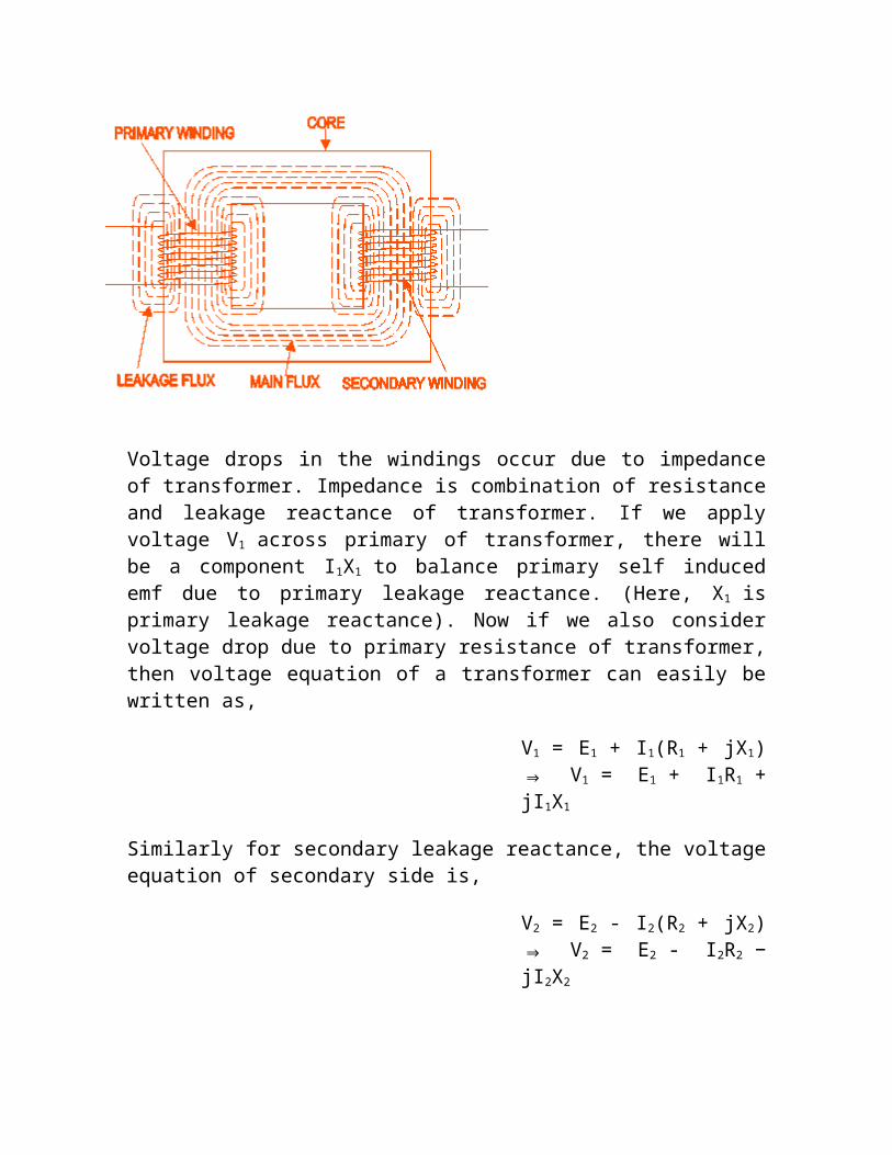
In ideal transformer all the flux will link with both primary and secondary winding but in reality it is impossible to link all the flux in transformer with both primary and secondary windings. Although maximum flux will link with both winding through the core of transformer but still there will be a small amount of flux which will link either winding not both. This flux is called leakage flux which will pass through the winding insulation and transformer insulating oil instead of passing through core. Due to this leakage flux in transformer, both primary and secondary winding have leakage reactance. These reactance of transformer is nothing but leakage reactance of transformer. This phenomena in transformer is known as Magnetic Leakage.
Voltage drops in the windings occur due to impedance of transformer. Impedance is combination of resistance and leakage reactance of transformer. If we apply voltage V1 across primary of transformer, there will be a component I1X1 to balance primary self induced emf due to primary leakage reactance. (Here, X1 is primary leakage reactance). Now if we also consider voltage drop due to primary resistance of transformer, then voltage equation of a transformer can easily be written as,

V1 = E1 + I1(R1 + jX1) ⇒ V1 = E1 + I1R1 + jI1X1
Similarly for secondary leakage reactance, the voltage equation of secondary side is,
V2 = E2 - I2(R2 + jX2) ⇒ V2 = E2 - I2R2 − jI2X2
Here in the figure above, the primary and secondary windings are shown in separate limbs and this arrangement could result a large leakage flux in transformer as because there is a big room for leakage. Leakage in primary and secondary could be eliminated it the windings could be made to occupy the same space. This of course is physically impossible but by placing secondary and primary in concentric manner can solve the problem in good extent.
Equivalent Circuit of TransformerEquivalent impedance of Transformer is essential to be calculated as because the electrical power transformer is an electrical power system equipment so for estimating different parameters of electrical power system it may be required to calculate total internal impedance of an electrical power transformerviewing from primary side or secondary side as per requirement. This calculation requires equivalent circuit of transformer referred to primary or equivalent circuit of transformer referred to secondary sides respectively. Percentage impedance is also very essential parameter of transformer. Special attention is to be given to this parameter during installing a transformer in an existing electrical power system. Percentage impedance of different power transformers should be properly matched during parallel operation of these transformers. The percentage impedance can be derived from equivalent impedance of transformer so it can be said that equivalent circuit of transformer is also required during calculation of % impedance.
Equivalent Circuit of Transformer referred to Primary

For drawing equivalent circuit of transformer referred to primary, first we have to establish generalequivalent circuit of transformer then we will modify it for referring from primary side. For doing this we first recall the complete vector diagram of a transformer which is shown in the figure below.
Let us consider the transformation ratio be,K = N1/N2 = E1/E2
In the figure right, the applied voltage to the primary is V1 and voltage across the the primary winding is E1. Total current supplied to primary is I1. So the voltage V1 applied to the primary, is partly dropped by I1Z1 or I1R1+ j.I1X1 before it appears across primary winding. The voltage appeared across winding is countered by primary induced emf E1. So voltage equation of this portion of the transformer can be written as
V1 - (I1R1 + j.I1X1) = E1
The equivalent circuit for that equation can be drawn as below,

From the vector diagram above it is found that total primary current I1has two components one is no - load component Io and other is load component I2′. As this primary current has two components or branches so there must be a parallel path with primary winding of transformer. This parallel path of current is known as excitation branch of equivalent circuit of transformer. The resistive and reactive branches of the excitation circuit can be represented as Ro = E1 / Iw and Xo = E1 / Iμ.
The load component I2′ flows through the primary winding of transformer and induced voltage across the winding is E1 as shown in the figure right. This induced voltage E1 transforms to secondary and it is E2 and load component of primary current I2′ is transformed to secondary as secondary current I2. Current of secondary is I2. So the voltage E2 across secondary winding, is partly dropped by I2Z2 or I2R2 + j.I2X2 before it appears across load. The load voltage is V2.The complete equivalent circuit of transformer is shown
below.

Now if we see the voltage drop in secondary from primary side then it would be ′K′ times greater and would be written as K.Z2.I2.Again I2′.N1 = I2.N2⇒ I2 = I2′.N1 / N2⇒ I2 = K.I2′Therefore,K.Z2.I2 = K.Z2.K.I2′= K2.Z2.I2′From above equation,Secondary impedance of transformer referred to primary is, Z2′ = K2.Z2
Hence, R2′ = K2.R2
and X2′ = K2.X2
So The complete equivalent circuit of transformer referred to primary is shown in the figure below,
Approximate Equivalent Circuit of Transformer
Since Io is very small compared to I1, it is less than 5% of full load primary current, Iochanges the voltage drop insignificantly. Hence, it is good approximation to ignore the excitation circuit in approximate equivalent circuit of transformer. The winding resistance and reactance being in series can now be combined into equivalent resistance and reactance of

transformer referred to any particular side. In this case it is side 1 or
primary side. Here V2′ = K.V2
Equivalent Circuit of Transformer referred to Secondary
In similar way approximate equivalent circuit of transformer referred to secondary can be drawn.Where, equivalent impedance of transformer referred to secondary, can be derived asZ1′ = Z1 / K2
Therefore,R1′ = R1 / K2 and X1′ = X1 / K2
Here, V1′ = V1 / K
Voltage Regulation of Transformer
What is Voltage Regulation?

Definition
The voltage regulation is the percentage of voltage difference between no load and full load voltages of a transformer with respect to its full load voltage.
Explanation of Voltage Regulation of Transformer
Say a electrical power transformer is open circuited means load is not connected with secondary terminals. In this situation the secondary terminal voltage of the transformer will be its secondary induced emf E2. Whenever full load is connected to the secondary terminals of the transformer, rated current I2 flows through the secondary circuit and voltage drops comes into picture. At this situation, primary winding will also draw equivalent full load current from source. The voltage drop in the secondary is I2Z2 where Z2 is the secondaryimpedance of transformer. If now, at this loading condition any one measures the voltage between secondary terminals, he or she will get voltage V2 across load terminals which is obviously less than no load secondary voltage E2 and this is because of I2Z2 voltage drop in the transformer.
Expression of Voltage Regulation of transformer
Expression of Voltage Regulation of Transformer, represented in percentage, is
Voltage regulation (%) = {(E2 − V2)/V2} X 100%
Voltage Regulation of Transformer for lagging Power Factor
Now we will derive the expression of voltage regulation in detail, say lagging Power Factor of the load is cosθ2, that means angle between secondary current and voltage is θ2
Here, from the above diagram,
OC = OA + AB + BC
Here, OA = V2
Here, AB = AEcosθ2 = I2R2cosθ2
and, BC = DEsinθ2 = I2X2sinθ2
Angle between OC & OD may be very small so it can be neglected and OD is considered nearly equal to OC i.e.
E2 = OC = OA + AB + BC
E2 = OC = V2 + I2R2cosθ2 + I2X2sinθ2.....................1
Voltage Regulation of transformer at lagging power factor,
Voltage Regulation (%) = {(E2 − V2)/ V2} X 100 % = {(I2R2cosθ2 +
I2X2sinθ2)/ V2} X 100 %
Voltage Regulation of Transformer for Leading Power Factor
Let's derive the expression of voltage regulation with leading current, say leading Power Factor of the load is cosθ2, that means angle between secondary current and voltage is θ2

Here, from the above diagram,
OC = OA + AB − BC
Here, OA = V2
Here, AB = AEcosθ2 = I2R2cosθ2
and, BC = DEsinθ2 = I2X2sinθ2
Angle between OC & OD may be very small so it can be neglected and OD is considered nearly equal to OC i.e.
E2 = OC = OA + AB − BC
E2 = OC = V2 + I2R2cosθ2 − I2X2sinθ2.....................2
Voltage Regulation of transformer at leading power factor,
Voltage Regulation (%) = {(E2 − V2)/ V2} X 100 % = {(I2R2cosθ2 −
I2X2sinθ2)/ V2} X 100 %
Losses in Transformer

As the electrical transformer is a static device, mechanical loss in transformer normally does not come into picture. We generally consider only electrical losses in transformer. Loss in any machine is broadly defined as difference between input power and output power.
When input power is supplied to the primary of transformer, some portion of that power is used to compensate core losses in transformer i.e.Hysteresis loss in transformer and Eddy Current loss in transformer core and some portion of the input power is lost as I2R loss and dissipated as heat in the primary and secondary winding, as because these windings have some internal resistance in them. The first one is called core loss or iron loss in transformer and later is known as ohmic loss or copper loss in transformer. Another loss occurs in transformer, known as Stray Loss, due to Stray fluxes link with the mechanical structure and winding conductors.
Copper loss in transformer
Copper loss is I2R loss, in primary side it is I12R1 and in secondary side it
is I22R2 loss, where I1 & I2 are primary & secondary current of transformer
and R1 & R2 are resistances of primary & secondary winding. As the both primary & secondary currents depend upon load of transformer, so copper loss in transformer vary with load.
Core losses in transformer
Hysteresis loss and eddy current loss, both depend upon magnetic properties of the materials used to construct the core of transformer and its design. So these losses in transformer are fixed and do not depend upon the load current. So core losses in transformer which is alternatively known as iron loss in transformerand can be considered as constant for all range of load.
Hysteresis loss in transformer is denoted as,
Wh = KhfBm1.6 watts
Eddy Current loss in transformer is denoted as,
We = Kef2Kf2Bm
2 watts

Where, Kh = Hysteresis Constant.
Ke = Eddy Current Constant.
Kf = form Constant.
Copper loss can simply be denoted as,
IL2R2′ + Stray loss
Where, IL = I2 = load of transformer, and R2′ is the resistance of transformer referred to secondary.
Now we will discuss Hysteresis loss and Eddy Current loss in little bit more details for better understanding the topic of losses in transformer
Hysteresis loss in transformer
Hysteresis loss in transformer can be explained in different ways. We will discuss two of them, one is physical explanation other is mathematical explanation.
Physical explanation of Hysteresis loss
The magnetic core of transformer is made of ′Cold Rolled Grain Oriented Silicon Steel′. Steel is very good ferromagnetic material. This kind of materials are very sensitive to be magnetized. That means whenever magnetic flux passes through,it will behave like magnet. Ferromagnetic substances have numbers of domains in their structure. Domain are very small region in the material structure, where all the dipoles are paralleled to same direction. In other words, the domains are like small small permanent magnet situated randomly in the structure of substance. These domains are arranged inside the material structure in such a random manner, that net resultant magnetic field of the said material is zero. Whenever external magnetic field or mmf is is applied to that substance, these randomly directed domains are arranged themselves in parallel to the axis of applied mmf. After removing this external mmf, maximum numbers of domains again come to random positions, but some few of them still remain in their changed position. Because of these unchanged domains the substance becomes slightly magnetized

permanently. This magnetism is called " Spontaneous Magnetism". To neutralize this magnetism some opposite mmf is required to be applied. The magneto motive force or mmf applied in the transformer core is alternating. For every cycle, due to this domain reversal there will be extra work done. For this reason, there will be a consumption of electrical energy which is known as Hysteresis loss of transformer.
Mathematical explanation of Hysteresis loss in transformer
Determination of Hysteresis loss
Consider a ring of ferromagnetic specimen of circumference L meter, cross - sectional area a m2 and N turns of insulated wire as shown in the picture beside,
Let us consider, the current flowing through the coil is I amp,
Magnetizing force,
Let, the flux density at this instant is B,Therefore, total flux through the ring, Φ = BXa Wb

As the current flowing through the solenoid is alternating, the flux produced in the iron ring is also alternating in nature, so the emf (e′) induced will be expressed as,
According to Lenz,s law this induced emf will oppose the flow of current, therefore, in order to maintain the current I in the coil, the source must
supply an equal and opposite emf. Hence applied emf ,
Energy consumed in short time dt, during which the flux density has

changed,
Thus, total work done or energy consumed during one complete cycle of
magnetism,
Now aL is the volume of the ring and H.dB is the area of elementary strip of B - H curve shown in the figure above,
= total area enclosed by Hysteresis Loop.

Therefore, Energy consumed per cycle = volume of the ring X area of hysteresis loop.In the case of transformer, this ring can be considered as magnetic core of transformer. Hence this work done is nothing but electrical energy loss in transformer core and this is known as hysteresis loss in transformer.
What is Eddy Current loss ?
In transformer we supply alternating current in the primary, this alternating current produces alternating magnetizing flux in the core and as this flux links with secondary winding there will be induced voltage in secondary, resulting current to flow through the load connected with it. Some of the alternating fluxes of transformer may also link with other conducting parts like steel core or iron body of transformer etc. As alternating flux links with these parts of transformer, there would be an locally induced emf. Due to these emfs there would be currents which will circulate locally at that parts of the transformer. These circulating current will not contribute in output of the transformer and dissipated as heat. This type of energy loss is called eddy current loss of transformer. This was a broad and simple explanation of eddy current loss. The detail explanation of this loss is not in the scope of discussion in that chapter.
Open Circuit Test and Short Circuit Test on TransformerThese two tests are performed on a transformer to determine (i) equivalent circuit of transformer (ii)voltage regulation of transformer (iii) efficiency of transformer. The power required for these Open Circuit test and Short Circuit test on transformer is equal to the power loss occurring in the transformer.
Open Circuit Test on Transformer
The connection diagram for open circuit test on transformer is shown in the figure. A voltmeter, wattmeter, and an ammeter are connected in LV side of the transformer as shown. The voltage at rated frequency is applied to that LV side with the help of a variac of variable ratio auto transformer. The HV side of the transformer is kept open. Now with help of variac applied voltage is slowly increase until the voltmeter gives reading equal to the rated voltage of the LV side. After reaching at rated

LV side voltage, all three instruments reading (Voltmeter, Ammeter and Wattmeter readings) are recorded. The ammeter reading gives the no load current Ie. As no load current Ie is quite small compared to rated current of the transformer, the voltage drops due to this current then can be taken as negligible. Since, voltmeter reading V1 can be considered equal to secondary induced voltage of the transformer. The input power during test is indicated by wattmeter reading. As the transformer is open circuited, there is no output hence the input power here consists of core losses in transformer and copper loss in transformer during no load condition. But as said earlier, the no load current in the transformer is quite small compared to full load current so copper loss due to the small no load current can be neglected. Hence the wattmeter reading can be taken as equal to core losses in transformer. Let us consider wattmeter reading is Po.
Po = V1 2/Rm
Where Rm is shunt branch resistance of transformer.If, Zm is shunt branch impedance of transformer.Then, Zm = V1/ Ie.Therefore, if shunt branch reactance of transformer is Xm Then, (1/ Xm)2 = (1/ Zm)2 - (1/ Rm)2
These values are referred to the LV side of transformer as because the test is conduced on LV side of transformer. These values could easily be referred to HV side by multiplying these values with square of transformation ratio.
Therefore it is seen that the open circuit test on transformer is used to determine core losses in transformer and parameters of shunt branch of the equivalent circuit of transformer.

Short Circuit Test on Transformer
The connection diagram for short circuit test on transformer is shown in the figure. A voltmeter, wattmeter, and an ammeter are connected in HV side of the transformer as shown. The voltage at rated frequency is applied to that HV side with the help of a variac of variable ratio auto
transformer. The LV side of the transformer is short circuited . Now with help of variac applied voltage is slowly increase until the ammeter gives reading equal to the rated current of the HV side. After reaching at rated current of HV side, all three instruments reading (Voltmeter, Ammeter and Wattmeter readings) are recorded. The ammeter reading gives the primary equivalent of full load current IL. As the voltage, applied for full load current in short circuit

test on transformer, is quite small compared to rated primary voltage of the transformer, the core losses in transformer can be taken as negligible here. Let’s, voltmeter reading is Vsc. The input power during test is indicated by wattmeter reading. As the transformer is short circuited, there is no output hence the input power here consists of copper losses in transformer. Since, the applied voltage Vsc is short circuit voltage in the transformer and hence it is quite small compared to rated voltage so core loss due to the small applied volate can be neglected. Hence the wattmeter reading can be taken as equal to copper losses in transformer. Let us consider wattmeter reading is Psc.
Psc = Re.IL2
Where Re is equivalent resistance of transformer.If, Ze is equivalent impedance of transformer.Then, Ze = Vsc/ IL.Therefore, if equivalent reactance of transformer is Xe Then, Xe
2 = Ze2 - Re
2
These values are referred to the HV side of transformer as because the test is conduced on HV side of transformer. These values could easily be referred to LV side by dividing these values with square of transformation ratio.
Therefore it is seen that the Short Circuit test on transformer is used to determine copper loss in transformer at full load and parameters of approximate equivalent circuit of transformer.
Auto Transformer
What is Auto Transformer ?
Auto transformer is kind of electrical transformer where primary and secondary shares same common single winding.
Theory of Auto Transformer

In Auto Transformer, one single winding is used as primary winding as well as secondary winding. But in two windings transformer two different windings are used for primary and secondary purpose. A diagram of auto transformer is shown below, The winding AB of total turns N1 is considered as primary winding. This winding is tapped from point ′C′ and the portion BC is considered as secondary. Let's assume the number of turns in between points ′B′ and ′C′ is N2.
If V1 voltage is applied across the winding i.e. in between ′A′ and ′C′. So voltage per turn in this winding is V1/N1. Hence, the voltage across the portion BC of the winding, will be V1/N1 X N2 and from the figure above, this voltage is V2.
Hence, V1/V2 X N2 = V2
V2/V1 = N2/N1 = Constant = k
As BC portion of the winding is considered as secondary, it can easily be understood that value of constant ′k′ is nothing but turns ratio or voltage ratio of that Auto Transformer.
When load is connected between secondary terminals i.e.between ′B′ and ′C′, load current I2 starts flowing .The current in the secondary winding or common winding is the difference of I2 & I1.
Copper savings in Auto Transformer

Now we will discuss the savings of copper in auto transformer compared to conventional two windingselectrical power transformer.We know that weight of copper of any winding depends upon its length and cross - sectional area. Again length of conductor in winding is proportional to its number of turns and cross - sectional area varies with rated current.
So weight of copper in winding is directly proportional to product of number of turns and rated current of the winding.Therefore, weight of copper in the section AC proportional to
(N1 − N2)I1
and similarly, weight of copper in the section BC proportional to
N2( I2 − I1)
Hence, total weight of copper in the winding of Auto Transformer proportional to
(N1 − N2)I1 + N2( I2 − I1)⇒ N1I1 − N2I1 + N2I2 − N2I1⇒ N1I1 + N2I2 − 2N2I1⇒ 2N1I1 − 2N2I1 (Since, N1I1 = N2I2)⇒ 2(N1I1 − N2I1)
In similar way it can be proved, the weight of copper in two winding transformer is proportional to,
N1I1 + N2I2⇒ 2N1I1 (Since, in a transformer N1I1 = N2I2)
Let's assume, Wa and Wtw are weight of copper in auto transformer and two winding transformer respectively,
Hence, Wa ⁄ Wtw = 2(N1I1 −
N2I1) ⁄ 2(N1I1)
= (N1I1 − N2I1) ⁄ (N1I1)
= 1 − (N2I1) ⁄ (N1I1)

= 1 − N2 ⁄ N1
= 1 − k
∴ Wa = Wtw(1 − k)⇒Wa = Wtw − kWtw
∴ Saving of copper in auto transformer compared to two winding transformer,⇒Wtw − Wa = kWtw
Auto transformer employs only single winding per phase as against two distinctly separate windings in a conventional power transformer. Advantages of using auto transformer. For transformation ratio = 2, the size of the auto transformer would be approximately 50% of the corresponding size of two winding transformer. For transformation ratio say 20 however the size would be 95%. The saving in cost is of course not in the same proportion. The saving of cost is appreciable when the ratio of transformer is low, that is lower than 2.
Disadvantages of using Auto Transformer
But auto transformer has the following disadvantages:
1. Because of electrical conductivity of the primary and secondary windings the lower voltage circuit is liable to be impressed upon by higher voltage. To avoid breakdown in the lower voltage circuit, it

becomes necessary to design the low voltage circuit to e\withstand higher voltage.
2. The leakage flux between the primary and secondary windings is small and hence the impedance is low. This results into severer short circuit currents under fault conditions.
3. The connections on primary and secondary sides have necessarily to be same, except when using interconnected starring connections. This introduces complications due to changing primary and secondary phase angle particularly in the case-by-case of delta / delta connection.
4. Because of common neutral in a star / star connected auto transformer it is not possible to earth neutral of one side only. Both their sides have to have their neutrality either earth or isolated.
5. It is more difficult to preserve the electromagnetic balance of the winding when voltage adjustment tappings are provided. It should be known that the provision of adjusting tapping on an auto transformer increases considerably the frame size of the transformer. If the range of tapping is very large, the advantages gained in initial cost is lost to a great event
Tertiary Winding of Transformer
What is tertiary winding? What is Three Winding Transformer ?
In some high rating transformer, one winding, in addition to its primary and secondary winding, is used. This additional winding, apart from primary and secondary windings, is known as Tertiary Winding of Transformer. Because of this third winding, the transformer is called Three Winding Transformer or 3 Winding Transformer.
Advantages of using tertiary winding in transformer
Tertiary Winding is provided in Electrical Power Transformer to meet one or more of the following requirements1. It reduces the unbalancing in the primary due to unbalancing in three phase load

2. It redistributed the folw of fault current3. Sometime it is requred to supply an auxiliary load in different voltage level in addition to its main secondary load. This secondary load can be taken from tertiary winding of three winding transformer.4. As the tertiary winding is connected in delta formation in 3 winding transformer, it assists in limitation of fault current in the event of a short circuit from line to neutral.
Stabilization by tertairy winding of transformer
In star - star transformer comprising three single units or a single unit with 5 limb core offers high impedance to the flow of unbalanced load between the line and neutral. This is because, in both of these transformer, there is very low reluctance return path of unbalanced flux.If any transformer has N - turns in winding and reluctance of the magnetic path is RL, then,
mmf = N.I = ΦRL ....... (1) Where I and Φ are current and flux in the transformer.Again, induced voltage V = 4.44ΦfN⇒ V ∝ Φ⇒ Φ = K.V (Where K is constant)....... (2)
Now, from equation (1) & (2) , it can be rewritten as,
N.I = K.V.RL⇒ V/I = N/(K.RL) ⇒ Z = N/(K.RL)⇒ Z ∝ 1/RL
From,this above mathemetical expression it is found that impenance is inversely proportional to reluctance. The impedance offered by the return path of unbalanced load current, is very high where very low reluctance return path is provided for unbalanced

flux. In other words, very high impedance to the flow of unbalanced current in 3 phase system between line and neutral. Any unbalanced current in three phase ssytem can be divided in to three sets of componants like wise positive sequence, negative sequence and zero sequence componants. The zerosequence current actually co-phasial current in three lines. If value of co-phasial current in each line is Io, then total current flows through the neutral of secondary side of transformer is In = 3.Io. This current can not be balanced by primary current as the zero sequence current can not flow through the isolated neutralstar connected primary. Hence the said current in the secondary side set up a magnetic flux in the core. As we earlier in this chapter low reluctance path is available for the zero sequence flux in a bank of single phase units and in the 5 limb core consequently the impedance offered to the zero sequence current is very high. The delta connected tertiary winding of transformer permits the circulation of zero sequence current in it. This circulating current in this delta winding balance the zero sequence component of unbalance load, hence prvent unnecessary development of unbalance zero sequence flux inthe transformer core. In few words it can be said that, placement of tertiary winding in star - star - neutral transformer considarbly reduces the zero sequnce impedance of transformer.
Rating of tertiary winding of transformer
Rating of tertiary winding of transformer depends upon its use. If it has to supply additional load, its winding cross - section and design philosophy is decided as per load and three phase dead short circuit on its terminal with power flow from both sides of HV & MV.

In case it is to be provided for stabilizing purpose only, its cross - section and design has to be decided from thermal and mechanical consideration for the short duration fault currents during various fault conditions single line - to - ground fault being the most onerous.
Parallel operation of Transformers
Why " parallel operation of transformers " is required ?
It is economical to installed numbers of smaller ratedtransformers in parallel than installing a bigger ratedelectrical power transformer. This has mainly the following advantages,
1) To maximize electrical power system efficiency: Generally electrical power transformer gives the maximum efficiency at full load. If we run numbers oftransformers in parallel, we can switch on only those transformers which will give the total demand by running nearer to its full load rating for that time. When load increases we can switch no one by one other transformer connected in parallel to fulfill the total demand. In this way we can run the system with maximum efficiency.
2) To maximize electrical power system availability: If numbers of transformers run in parallel we can take shutdown any one of them for maintenance purpose. Other parallel transformers in system will serve the load without total interruption of power.
3) To maximize power system reliability: if nay one of the transformers run in parallel, is tripped due to fault otherparallel transformers is the system will share the load hence power supply may not be interrupted if the shared loads do not make other transformers over loaded.
4) To maximize electrical power system flexibility: Always there is a chance of increasing or decreasing future demand of power system. If it is predicted that power demand will be increased in future, there must be a provision of connecting transformers in system in parallel to fulfill the extra demand because it is not economical from business point of view to install a bigger rated single transformer by forecasting the increased future demand as it is unnecessary investment of money. Again if future

demand is decreased, transformers running in parallel can be removed from system to balance the capital investment and its return.
Conditions for parallel operation of transformers.
When two or more transformers are run in parallel they must satisfy the following conditions for satisfactory performance. These are the conditions for parallel operation of transformers.
a) same voltage ratio of transformerb) same percentage impedancec) same polarityd) same phase sequence
same voltage ratio
If two transformers of different voltage ratio, are connected in parallel with same primary supply voltage, there will be a difference in secondary voltages. Now say the secondary of these transformers are connected to same bus, there will be a circulating current between secondaries and therefore between primaries also. As the internal impedance of transformer is small, a small voltage difference may cause sufficiently high circulating current causing unnecessary extra I2R loss.
Same percentage impedance
The current shared by two transformers running in parallel should be proportional to their MVA ratings. Again, current carried by these transformers are inversely proportional to their internal impedance. From these two statements it can be said that impedance of transformers running in parallel are inversely proportional to their MVA ratings. In other words percentage impedance or per unit values of impedance should be identical for all the transformers run in parallel.
Same polarity
Polarity of all transformers run in parallel should be same otherwise huge circulating current flows in the transformer but no load will be fed from these transformers. Polarity of transformer means the instantaneous direction of induced emf in secondary. If the instantaneous directions of

induced secondary emf in two transformers are opposite to each other when same input power is fed to the both of the transformers, the transformers are said to be in opposite polarity. If the instantaneous directions of induced secondary emf in two transformers are same when same input power is fed to the both of the transformers, the transformers are said to be in same polarity.
Same phase sequence
The phase sequence or the order in which the phases reach their maximum positive voltage, must be identical for two parallel transformers. Otherwise, during the cycle, each pair of phases will be short circuited.
The above said conditions must be strictly followed for parallel operation of transformers but totally identical percentage impedance of two different transformers is difficult to achieve practically that is why the the transforms run in parallel may not have exactly same percentage impedance but the values would be as nearer as possible.
Transformer Cooling SystemThe main source of heat generation in transformer is its copper loss or I2R loss. Although there are other factors contribute heat in transformer such as hysteresis & eddy current losses but contribution of I2R loss dominate them. If this heat is not dissipated properly, the temperature of the transformer will rise continually which may cause damages in paper insulation and liquid insulation medium of transformer. So it is essential to control the temperature within permissible limit to ensure the long life of transformer by reducing thermal degradation of its insulation system. In Electrical Power transformer we use externaltransformer cooling system to accelerate the dissipation rate of heat of transformer.There are different transformer cooling methods available for trans former, we will now explain one by one.
Different Transformer Cooling Methods

For accelerating cooling different transformer cooling methods are used depending upon their size and ratings. We will discuss these one by one below,
ONAN Cooling of Transformer
This is the simplest transformer cooling system. The full form of ONAN is "Oil Natural Air Natural". Here natural convectional flow of hot oil is utilized for cooling. In convectional circulation of oil, the hot oil flows to the upper portion of the transformer tank and the vacant place is occupied by cold oil. This hot oil which comes to upper side, will dissipate heat in the atmosphere by natural conduction, convection & radiation in air and will become cold. In this way the oil in the transformer tank continually circulate when the transformer put into load. As the rate of dissipation of heat in air depends upon dissipating surface of the oil tank, it is essential to increase the effective surface area of the tank. So additional dissipating surface in the form of tubes or radiators connected to the transformer tank. This is known as radiator of transformer or radiator bank of transformer. We have shown below a simplest form on Natural Cooling or ONAN Cooling arrangement of an earthing transformer below.


ONAF Cooling of Transformer
Heat dissipation can obviously be increased, if dissipating surface is increased but it can be make further faster by applying forced air flow on that dissipating surface. Fans blowing air on cooling surface is employed. Forced air takes away the heat from the surface of radiator and provides better cooling than natural air. The full form of ONAF is "Oil Natural Air Forced". As the heat dissipation rate is faster and more in ONAF transformer cooling method than ONAN cooling system, electrical power transformer can be put into more load without crossing the permissible temperature limits.
OFAF Cooling of Transformer
In Oil Forced Air Natural cooling system of transformer, the heat dissipation is accelerated by using forced air on the dissipating surface but circulation of the hot oil in transformer tank is natural convectional
flow. The heat dissipation rate can be still increased further if this oil circulation is accelerated by applying some force. In OFAF cooling system the oil is forced to circulate within the closed loop of transformer tank by means of oil pumps. OFAF means "Oil Forced Air Forced" cooling methods of transformer. The main advantage of this system is that it is compact system and for same cooling capacity OFAF occupies much less space than farmer two systems of transformer cooling. Actually in Oil Natural cooling system, the heat comes out from conducting part of the transformer is displaced

from its position, in slower rate due to convectional flow of oil but in forced oil cooling system the heat is displaced from its origin as soon as it comes out in the oil, hence rate of cooling becomes faster.
OFWF Cooling of Transformer
We know that ambient temperature of water is much less than the atmospheric air in same weather condition. So water may be used as better heat exchanger media than air. In OFWF cooling system of transformer, the hot oil is sent to a oil to water heat exchanger by means of oil pump and there the oil is cooled by applying sowers of cold water on the heat exchanger's oil pipes. OFWF means "Oil Forced Water Forced" cooling in transformer.
ODAF Cooling of Transformer
ODAF or Oil Directed Air Forced Cooling of Transformer can be considered as the improved version of OFAF. Here forced circulation of oil directed to flow through predetermined paths in transformer winding. The cool oil entering the transformer tank from cooler or radiator is passed through the winding where gaps for oil flow or pre-decided oil flowing paths between insulated conductor are provided for ensuring faster rate of heat transfer. ODAF or Oil Directed Air Forced Cooling of Transformer is generally used in very high rating transformer.
ODWF Cooling of Transformer
ODAF or Oil Directed Water Forced Cooling of Transformer is just like ODAF only difference is that here the hot oil is cooled in cooler by means of forced water instead of air. Both of these transformer cooling methods are called Forced Directed Oil Cooling of transformer
Core of Transformer
Purpose of Transformer Core
In a electrical power transformer there are primary, secondary and may be tertiary windings. The performance of a transformer mainly depends upon the flux linkages between these windings. For efficient flux linking between these winding one low reluctance magnetic path common to all

windings, should be provided in the transformer. This low reluctance magnetic path in transformer is known as core of transformer.
Influence of Diameter of Transformer Core
Let us consider, the diameter of transformer core be ′D′Then, cross-sectional area of the core,
A = πD2/4,
Now, voltage per turn
E = 4.44.φm.f= 4.44.A.Bm.f
Where Bm is the maximum flux density of the core.
= 4.44πD2Bsub>mf/4
E is proportional to D2
Therefore voltage per turn is increased with increase in diameter of transformer core Again if voltage across the winding of transformer is V
Then V = eN, where N is the number of turns in windingIf V is constant e is inversely proportional to N. And hence D2 is inversely proportional to N. So diameter of the core is increased, the number of turns in the transformer winding reduced. Reduction of number of turns, reduction in height of the core legs. In-spite of reduction of core legs height, increased in core diameter, results, increased in overall diameter of magnetic core of transformer. This increased steel weight ultimately leads to increased core losses in transformer. Increased diameter of the core leads to increase the mean diameter on the winding. In – spite of increased diameter of the winding turns, reduced the number of turns in the winding, leads to lesscopper loss in transformer.
So we go on increasing diameter of the transformer core, losses in the transformer core will be increased but at the same time load loss or copper loss in transformer is reduced. On the other hand if diameter of the core is decreased, the weight of the steel in the core is reduced which leads to less core loss of transformer, but in the same time this leads to increase in number of turns in the winding, means increase in

copper weight, which leads to extra copper loss in transformer. So diameter of the core must be optimized during design of transformer core, considering the both aspect.
Material for Transformer Core
The main problem with transformer core is, its hysteresis loss and eddy current loss in transformer.Hysteresis loss in transformer mainly depends upon its core materials. It is found that a small quantity of silicon alloyed with low carbon content steel produces, material for transformer core which has low hysteresis loss and high permeability. As the increasing demand bof power ratings, it is required to further reduce the core losses and for that aother technique is employed on steel, which is known as cold rolling. This technique arrange the orientation of grain in ferromagnetic steel in the direction of rolling.The core steel which has under gone through the both silicon alloying and cold rolling treatments, is commonly known as CRGOS or Cold Rolled Grain Oriented Silicon Steel. This material is now universally used for manufacturing for transformer core.Although this material has low specific iron loss but still it has some disadvantages, Like it is susceptible to increase loss due to flux flow in direction other than grain orientation and it also susceptible to impaired performance due to impact of bending, blanking the cutting CRGOS sheet. Both surfaces of the sheets are provided with an insulating of oxide coating.
Optimum Design of Cross – Section of Transformer Core
The maximum flux density of CRGO steel is about 1.9 Tesla. Means the steel becomes saturated at the flux density 1.9 Tesla. One important criteria for design of transformer core, is that, it must not be saturated during transformer’s normal operation mode. Voltages of transformer depend upon its total magnetizing flux. Total magnetizing flux through core is nothing but product of flux density and cross – sectional area of the core. Hence, flux density of a core can be controlled by adjusting the cross sectional area of the core during its design.

The idea shape of cross – section of a transformer core is circular. For making perfect circular cross section, each and every successive lamination steel sheet should be cut in different dimension and size. This is absolutely uneconomical for practical manufacturing. In reality, manufacturers use different groups or packets of predefined number of same dimension lamination sheets. The group or packet is a block of laminated sheets with a predefined optimum height (thickness). The core is assembly of these blocks in such a successive manner as per their size from core central line that it gives a optimum circular shape of the cross – section. Such typical cross – section is shown in the figure below.
Oil ducts are needed for cooling the core. Cooling ducts are necessary because hot – spot temperature may rise dangerously high and their number depends on the core diameter, materials used for core. In addition to that clamp plates made of steel are needed on either sides of the core to clamping the laminations. The sheet steel lamination blocks, oil ducts, and clamping plates all should lie within the peripheral of optimum core circle.
The net sectional area is calculated from the dimensions of various packets and allowance is made for the space lost between lamination (known as stacking factor ) which for sheet steel of 0.28 mm thickness with insulation coating is approximately 0.96. Area is also deducted for oil ducts. The ratio of net cross sectional area of core to the gross cross - sectional area inside the imaginary peripheral circle is known as Utilization Factor of transformer core. By increasing numbers of steps of improves the Utilization Factor but at the same time it increases

manufacturing cost. Optimum numbers of steps are between 6 (for smaller diameter) to 15 (larger diameter).
Manufacturing of transformer core
During core manufacturing in factory some factors are taken into consideration,a) Higher reliabilityb) Reduction in iron loss in transformer and magnetizing currentc) Lowering material cost and labor costd) abatement of noise levelsQuality checking is necessary at very step of manufacturing to ensure quality and reliability. The sheet steel must be tested for ensuring the specific core loss or iron loss values. The lamination should be properly checked and inspected visually, rusty and bend lamination to be rejected. For reducing the transformer noises the laminations should be tightly clamped together and punch holes should be avoided as far as possible to minimize cross flux iron losses. The air gap a the joint of limbs and yokes should be reduced as much as possible for allowing maximum smooth conducting paths for magnetizing current.
Corner Jointing of Limbs with Yokes
Core losses in transformer mainly due to,1) magnetic flux flow along the direction of the grain orientation,2) magnetic flux flow perpendicular to the direction of the grain orientation, this is also known as cross grain iron losses. The cross grain loss mainly occurs in the zones of Corner Jointing of Limbs with Yokes and it can be controlled to some extent by applying special corner jointing techniques. There are normally two types of joints used in transformer core1) Interleaved Joints 2) Mited Joints

Interleaved Joints in transformer core
Interleaved Joint in transformer core is the simplest form of joints. This joint is is shown in the figure. The flux leaves and enters at the joint in perpendicular to grain orientation. Hence Cross Grain losses is high in this type of joints. But considering the low manufacturing cost it is preferable to use in small rating transformer.

Mitred Joints in transformer core
Here the laminations are cut at 45o. The limbs and yoke lamination edges are placed face to face at the Mitred Joints in transformer core. Here the flux enters and leaves the laminations gets smooth path in the direction of its flow. Hence cross grain loss is minimum here. However it involves extra manufacturing cost but it is preferable to use inelectrical power transformer where loss minimization is of the main criteria of design of transformer core.
Insulating Transformer Oil
Introduction of Insulating Oil
Insulating oil in an electrical power transformer is commonly known as Transformer Oil. It is normally obtained by fractional distillation and subsequent treatment of crude petroleum. That is why this oil is also known as Mineral Insulating Oil. Transformer Oil serves mainly tow purposes one it is liquid insulation in electrical power transformer and two it dissipates heat of the transformer e.i. acts as coolant. In addition to these, this oil serves other two purposes, it helps to preserve the core and winding as these are fully immersed inside oil and another important purpose of this oil is, it prevents direct contact of atmospheric oxygen with cellulose made paper insulation of windings, which is susceptible to oxidation.
Types of Transformer Oil
Generally there are two types of Transformer Oil used in transformer,
1. Paraffin based Transformer Oil
2. Naphtha based Transformer Oil
Naphtha oil is more easily oxidized than Paraffin oil. But oxidation product i.e. sludge in the naphtha oil is more soluble than Paraffin oil. Thus sludge of naphtha based oil is not precipitated in bottom of the transformer. Hence it does not obstruct convection circulation of the oil, means it does not disturb the transformer cooling system. But in the case

of Paraffin oil although oxidation rate is lower than that of Naphtha oil but the oxidation product or sludge is insoluble and precipitated at bottom of the tank and obstruct the transformer cooling system. Although Paraffin based oil has above mentioned disadvantage but still in our country it is generally used because of its easy availability. Another problem with paraffin based oil is its high pour point due to the wax content, but this does not effect its use due to warm climate condition of India.
Properties of Transformer Insulating Oil
Some specific parameters of insulating oil should be considered to determined the serviceability of that oil.
Parameters of Transformer Oil
The parameters of Transformer Oil are categaorised as,
1. Electrical Parameters – Dielectric Strength , Specific Resistance, Dielectric Dissipation Factor.
2. Chemical Parameter - Water Content, Acidity, Sludge Content.
3. Physical Parameters - Inter Facial Tension, Viscosity, Flash Point, Pour Point.
Electrical Parameter of Transformer Oil
Dielectric Strength of Transformer Oil

Dielectric Strength of Transformer Oil is also knlown as Breakdown Voltage of transformer oil or BDV of transformer oil. Break down voltage is measured by observing at what voltage, sparking strants between two electrods immerged in the oil, separated by specific gap. low value of BDV indicates presence of moisture content and conducting substances in the oil. For measuring BDV of transformer oil, portable BDV measuring kit is generally available at site. In this kit, oil is kept in a pot in which one pair of electrodes are fixed with a gap of 2.5 mm (in some kit it 4mm) between them. Now slowly rising voltage is applied between the electrodes. Rate of rise of voltage is generally controlled at 2KV/s and observe the voltage at which sparking starts between the electrodes. That means at which voltage Dielectric Strength of transformer oil between the electrodes has been broken
down. Generally this measurement is taken 3 to 6 times in same sample of oil and the average value of these reading is taken. BDV is important and popular test of transformer oil, as it is primary indication of health of oil and it can be easily carried

out at site.Dry and clean oil gives BDV results, better than the oil with moisture content and other conducting impurities. Minimum Breakdown Voltage of transformer oil orDielectric Strength of transformer oil at which this oil can safely be used in transformer, is considered as 30 KV.
Specific Resistance ( Resistivity ) of Transformer Oil
This is another important property of transformer oil. This is measure of DC resistance between two opposite sides of one cm3 block of oil. Its unit is taken as ohm-cm at specific temperature. With increase in temperature the resistivity of oil decreases rapidly. Just after charging a transformer after long shut down, the temperature of the oil will be at ambient temperature and during full load the temperature will be very high and may go upto 90oC at over load condition. So resistivity of the insulating oil must be high at room temperature and also it should have good value at high temperature as well. That is why specific resistance or resistivity of transformer oil should be measured at 27oC as well as 90oC.
Minimum standard Specific Resistance of Transformer oil at 90oC is 35X 1012 ohm – cm and at 27oC it is 1500X1012 ohm – cm.
Dielectric Dissipation Factor of tan delta of Transformer oil
Dielectric Dissipation Factor is also known as loss factor or tan delta of transformer oil. When a insulating materials is placed between live part and grounded part of an electrical equipment, leakage current will flow. As insulating material is dielectric in nature the current through the insulation ideally leads the voltage by 90o. Here voltage means the instantaneous voltage between live part and ground of the equipment. But in reality no insulating materials are perfect dielectric in nature. Hence current through the insulator will lead the voltage with an angle little bit shorter than 90o. Tangent of the angle by which it is short of 90o is called Dielectric Dissipation Factor or simply tan delta of transformer oil. More clearly, the leakage current through an insulation does have two component one is capacitive or reactive and other one is resistive or active. Again it is clear from above diagram, value of ′δ′ which is also

known as loss angle, is smaller, means resistive component of the current IR is smaller which indicates high resistive property of the insulating material. High resistive insulation is good insulator. Hence it is desirable to have loss angle as small as possible. So we should try to keep the value of tanδ as small as possible. High value of this tanδ is an indication of presence of contaminants in transformer oil. Hence there is a clear relationship between tanδ and resistivity of insulating oil. If resistivity of the insulating oil is decreased, the value of tandelta increases and vice versa. So both resistivity test and tan delta test of transformer oil are not normally required for same piece of insulator or insulating oil.In one sentence it can be said that, tanδ is measure of imperfection of dielectric nature of insulation materials like oil.
Chemical Parameters of Transformer Oil
Water Content in Transformer Oil
Moisture or Water Content in Transformer Oil is highly undesirable as it affects adversely the dielectric properties of oil. The water content in oil also affects the paper insulation of the core and winding of transformer. Paper is highly hygroscopic in nature. Paper absorbs maximum amount of water from oil which affects paper insulation property as well as reduced its life. But in loaded transformer, oil becomes hotter, hence the solubility of water in oil increases as a result the paper releases water and increase thewater content in transformer oil. Thus the temperature of the oil at the time of taking sample for test is very important. During oxidation acid are formed in the oil the acids give rise

the solubility of water in the oil. Acid coupled with water further decompose the oil forming more acid and water. This rate of degradation of oil increases. The water content in oil is measured as pm(parts per million unit).Water content in oil is allowed up to 50 ppm as recommended by IS – 335(1993). The accurate measurement of water content at such low levels requires very sophisticated instrument like Coulometric Karl Fisher Titrator .
Acidity of Transformer Oil
Acidity of transformer oil, is harmful property. If oil becomes acidic, water content in the oil becomes more soluble to the the oil. Acidity of oil detoriates the insulation property of paper insulation of winding. Acidity accelerates thee oxidation process in the oil. Acid also includes rusting of iron in presence of moisture. The acidity of transformer oil is measure of its acidic constituents of contaminants. Acidity of oil is express in mg of KOH required to neutralize the acid present in a gram of oil. This is also known as neutralization number.
Physical Parameters of transformer oil
Inter Facial Tension of Transformer Oil
Inter Facial Tension between the water and oil interface is the way to measure molecular attractive force between water and oil. It is measured in Dynes/cm or miliNeuton/meter. Inter facial Tension is exactly useful for determining the presence of polar contaminants and oil decay products. Good new oil generally exhibits high inter facial tension. Oil oxidation contaminants lower the IFT.
Flash Point of Transformer Oil
Flash point of transformer oil is the temperature at which oil gives enough vapors to produce a flammable mixture with air. This mixture gives momentary flash on application of flame under standard condition. Flash point is important because it specifies the chances of fire hazard in the transformer. So it is desirable to have very high flash point of transformer oil. In general it is more than 140o(>10o).
Pour Point of Transformer Oil

It is the minimum temperature at which oil just start to flow under standard test condition. Pour Point of Transformer Oil is an important property mainly at the places where climate is extremely cold. If the oil temperature falls bellow the pour point, transformer oil stops convection flowing and obstruct cooling in transformer. Paraffin based oil has higher value of pour point, compared to Naphtha based oil, but in India like country, it does not effect the use of Paraffin oil due tits warm climate condition. Pour Point of transformer oil mainly depends upon wax content in the oil. As Paraffin based oil has more wax content, it has higher pour point.
Viscosity of Transformer Oil
In few wards, Viscosity of Transformer Oil can be said that Viscosity is the resistance of flow, at normal condition. Obviously resistance to flow of transformer oil means obstruction of convection circulation of oil inside the transformer. A good oil should have low viscosity so that it offers less resistance to the convectional flow of oil thereby not affecting the cooling of transformer. Low viscosity of transformer oil is essential, but it is equally important that, the viscosity of oil should increase as less as possible with decrease in temperature. Every liquid becomes more viscous if temperature decreases.
Furfural Test or Furfuraldehyde Analysis of Transformer OilTransformer core and winding have mainly paper insulation. Base of paper is cellulose. The Cellulose has a structure of long chain of molecules. As the paper becomes aged, these long chains are broken into number of shorter parts. This phenomenon we often observe in our home. The pages of very old books become very much brittle. In transformer, the aging affect of paper insulation is accelerated due to oxidation occurs in oil. When insulating paper becomes mechanically weak, it can not withstand the mechanical stresses applied during electrical short circuit and leads to electrical breakdown.
It is therefore necessary to monitor the condition of paper insulation inside a power transformer.

It is not possible to bring out a piece of paper insulation from a transformer in service for testing purpose. But we are lucky enough, that there is a testing technique developed, where we can examine the condition of paper insulation without touching it. The method is called Furfuradehyde Analysis of in short Furfural test .
Although by Dissolved Gas Analysis one can predict the condition of the paper insulation primarily, but it is not very sensitive method. There is a guide line in IEC - 599, where it is told that if the ratio of CO2 and CO in DGA results is more than 11, it is predicted that the condition of paper insulation inside the transformer is not good. A healthy cellulose insulation gives that ratio in a range of 4 to 11. But still it is not a very sensitive way of monitoring the condition of paper insulation. Because CO2 and CO gases also produced during oil breakdown and sometimes the ratio may misleads the prediction.
When oil is soaked into paper, it is damaged by heat and some unique oil soluble compounds are realized and dissolved in the oil along with CO2 and CO. These compounds belong to theFurfuraldehyde group. These are some times called Furfural in short. Among all Furfurals compounds 2 - Furfural is the most predominant. These Furfural family compound can only be released from destructive heating of cellulose or paper. Furfuraldehyde Analysis is very sensitive as because damage of few grams of paper is noticeable in the oil even of a very large size transformer. It is a very significant diagnostic test. It is best test for assessing life of transformer. The rate of rise of percentage of Furfurals products in oil, with respect to time, is used for assessing the condition and remaining life of paper insulation in power transformer.
Over Fluxing in Transformer
Causes of Over Fluxing in Transformer
As per present day transformer design practice, the peak rated value of the flux density is kept about 1.7 to 1.8 Tesla, while the saturation flux density of CRGD steel sheet of core of transformer is of the order of 1.9 to 2 Tesla which corresponds to about 1.1 times the rated value. If during operation, an electrical power transformeris subjected to carry rather swallow more than above mentioned flux density as per its design limitations, the transformer is said to have faced over fluxing problem and consequent bad effects towards its operation and life.

Depending upon the design and saturation flux densities and the thermal time constants of the heated component parts, a transformer has some over excitation capacity. I.S. specification for electrical power transformer does not stipulate the short time permissible over excitation, though in a round about way it does indicate that the maximum over fluxing in transformer shall not exceed 110%.
The flux density in a transformer can be expressed by
B = C V/f, where, C = A constant, V = Induced voltage, f = Frequency.
The magnetic flux density is, therefore, proportional to the quotient of voltage and frequency (V/f). Over fluxing can, therefore, occur either due to increase in voltage or decrease in-frequency of both.
The probability of over fluxing is relatively high in step-up transformers in Power stations compared to step - down transformers in Sub-Stations, where voltage and frequency usually remain constant. However, under very abnormal system condition, over-fluxing trouble can arise in step-down Sub-Station transformers as well.
Effect of Over Fluxing in Transformers
The flux in a transformer, under normal conditions is confined to the core of transformer because of its high permeability compared to the surrounding volume. When the flux density in the increases beyond saturation point, a substantial amount of flux is diverted to steel structural parts and into the air. At saturation flux density the core steel will over heat.
Structural steel parts which are un-laminated and are not designed to carry magnetic flux will heat rapidly. Flux flowing in unplanned air paths may link conducing loops in the windings, loads, tank base at the bottom of the core and structural parts and the resulting circulating currents in these loops can cause dangerous temperature increase. Under conditions of excessive over fluxing the heating of the inner portion of the windings may be sufficiently extreme as the exciting current is rich in harmonies. It is obvious that the levels of loss which occur in the winding

at high excitation cannot be tolerated for long if the damage is to be a voided.
Physical evidences of damage due to over fluxing will very with the degree of over excitation, the time applied and the particular design of transformer. The Table given below summarizes such physical damage and probable consequences.
SLComponent involved
Physical evidences Consequences
1
Metallic support and surfaces structure for core and coils
Discolouration or metallic parts and adjacent insulation.Possible carbonized material in oil. Evolution ofcombustible gas.
Contamination of a oil and surfaces of insulation. Mechanical weakening of insulation Loosing of structure. Mechanical structure
2 WindingsDiscoloration winding insulation evolution of gas.
Electrical and mechanical weaking of winding insulation
3Lead conductors.
Discoloration of conductor insulation or support, evolution of gas.
Electrical and mechanical weakening of insulation, Mechanical Weakening of support.
4Core laminations.
Discolouration of insulating material in contact with core. Discoloration and carbonization of organic/lamination insulation Evaluation of gas.
Electrical weakening of major insulation (winding to core) increased interlaminar eddy loss.

5 Tank Blistering of paintsContamination of oil if paint inside tank is blistered.
It may be seen that metallic support structures for core and coil, windings, lead conductors, core laminations, tank etc. may attain sufficient temperature with the evolution of combustible gas in each case due to overfluxing of transformer and the same gas may be collected in Buchholz Relay with consequent Alarm/Trip depending upon the quantity of gas collected which again depends upon the duration of time the transformer is subjected to overfluxing.
Due to over fluxing in transformer its core becomes saturated as such induced voltage in the primary circuit becomes more or less constant. If the supply voltage to the primary is increased to abnormal high value, there must be high magnetising current in the primary circuit. Under such magnetic state of condition of transformer core linear relations between primary and secondary quantities (viz. for voltage and currents) are lost. So there may not be sufficient and appropriate reflection of this high primary magnetising current to secondary circuit as such mismatching of primary currents and secondary currents is likely to occur, causing differential relay to operate as we do not have overfluxing protection for sub-Stn. transformers.
Stipulated Withstand-Duration of Over Fluxing in Transformers
Over fluxing in transformer has sufficient harmful effect towards its life which has been explained. As overfluxing protection is not generally provided in step-down transformers of Sub-Station, there must be a stipulated time which can be allowed matching with the transformer design to withstand such overfluxing without causing appreciable damage to the transformer and other protections shall be sensitive enough to trip the transformer well within such stipulated time, if cause of overfluxing is not removed by this time.
It is already mentioned that the flux density 'B' in transformer core is proportional to v/f ratio. Power transformers are designed to withstand (Vn/fn x 1.1) continuously, where Vn is the normal highest r.m.s. voltage

and fn is the standard frequency. Core design is such that higher v/f causes higher core loss and core heating. The capability of a transformer to withstand higher v/f values i.e. overfluxing effect, is limited to a few minutes as furnished below in the Table
F = (V/f)/(Vn/fn) 1.1 1.2 1.25 1.3 1.4
Duration of with stand limit (minutes)
continuous 2 1 0.5 0
From the table above it may be seen that when over fluxing due to system hazards reaches such that the factor F attains a values 1.4, the transformer shall be tripped out of service instantaneously otherwise there may be a permanent damage.
Protection Against Over fluxing (v/f - Protection) in Transformer
The condition arising out of overfluxing does not call for high speed tripping. Instantaneous operation is undesirable as this would cause tripping on momentary system disturbances which can be borne safely but the normal condition must be restored or the transformer must be isolated within one or two minutes at the most.
Flux density is proportional to V/f and it is necessary to detect a ratio of V/f exceeding unity, V and f being expressed in per unit value of rated quantities. In a tyhpical scheme designed for over fluxing protection, the system voltage as measured by the voltages transformer is applied to a resistance to product a proportionate current; this current on being passed through a capacitor, produces a voltage drop which is proportional to the functioning in question i.e. V/f and hence to flux in the power transformer. This is accompanied with a fixed reference D.C. voltage obtained across a Zener diode. When the peak A.C. signal exceeds the D.C. reference it triggers a transistor circuit which operates two electromechanical auxiliary elements. One is initiated after a fixed time delay, the other after an additional time delay which is adjustable. The overfluxing protection operates when the ratio of the terminal voltage to frequency exceeds a predetermined setting and resets when the ratio

falls below 95 to 98% of the operating ratio. By adjustment of a potentiometer, the setting is calibrated from 1 to 1.25 times the ratio of rated volts to rated frequency.
The output from the first auxiliary element, which operates after fixed time delay available between 20 to 120 secs. second output relay operates and performs the tripping function.
It is already pointed out that high V/f occur in Generator Transformers and Unit-Auxiliary Transformers if full exaltation is applied to generator before full synchronous speed is reached. V/f relay is provided in the automatic voltage regulator of generator. This relay blocks and prevents increasing excitation current before full frequency is reached.
When applying V/f relay to step down transformer it is preferable to connect it to the secondary (L.V. saide of the transformer so that change in tap position on the H.V. is automatically taken care of Further the relay should initiate an Alarm and the corrective operation be done / got done by the operator. On extreme eventuality the transformer controlling breaker may be allowed to. trip.
Three Phase Transformer
Comparison between single Three Phase transformer and bank of three Single Phase transformers for three phase system
It is found that generation, transmission and distribution of electrical power are more economical in three phase system than single phase system. For three phase system three single phase transformers are required. Three phase transformation can be done in two ways, by using single three phase transformer or by using a bank of three single phase transformers. Both are having some advantages over other. Single 3 phase transformer costs around 15% less than bank of three single phase transformers. Again former occupies less space than later. For very big transformer, it is impossible to transport large three phase transformerto the site and it is easier to transport three single phase transformers which is erected separately to form a three phase unit. Another advantage of using bank of three single phase

transformers is that, if one unit of the bank becomes out of order, then the bank can be run as open delta.
Connection of Three Phase Transformer
A Varity of connection of three phase transformerare possible on each side of both a single 3 phase transformer or a bank of three single phase transformers.
Marking or labeling the different terminals of transformer.
Terminals of each phase of HV side should be labeled as capital letters, A, B, C, and those of LV side should be labeled as small letters, a, b, c. Terminal polarities are indicated by suffixes 1 & 2. Suffix 1’s indicate similar polarity ends and so do 2’s.
Star Star Transformer
Star Star Transformer is formed in a 3 phase transformer by connecting one terminal of each phase of individual side, together. The common terminal is indicated by suffix 1 in the figure below. If terminal with suffix 1 in both primary and secondary are used as common terminal, voltages of primary and secondary are in same phase. That is why this connection is called zero degree connection or 0o - connection.

If the terminals with suffix 1 is connected together in HV side as common point and the terminals with suffix 2 in LV side are connected together as common point, the voltages in primary and secondary will be in opposite phase. Hence, Star Star Transformer connection is called 180o - Connection, of three phase transformer.
Delta Detla Transformer
In delta delta transformer, 1 suffixed terminals of each phase primary winding will be connected with 2 suffixed terminal of next phase primary
winding. If primary is HV side, then A1 will be connected to B2, B1 will be connected to C2 and C1 will be connected to A2. Similarly in LV side 1 suffixed terminals of each phase winding will be connected with 2 suffixed terminals of next phase winding. That means, a1 will be connected to b2, b1 will be connected to c2 and c1 will be connected to a2. If transformer leads are taken out from primary and secondary 2 suffixed terminals of the winding, then there will be no phase difference between similar line voltages in primary and secondary. This delta delta transformer connection is zero degree connection or 0o - Connection.
But in LV side of transformer, if, a2 is connected to b1, b2 is connected to c1 and c2 is connected to a1. The secondary leads of transformer are taken out from 2 suffixed terminals of LV windings, and then similar line

voltages in primary and secondary will be in phase opposition. This connection is called 180o - Connection, of three phase transformer.
Star Delta Transformer
Here in star delta transformer, star connection in HV side is formed by connecting all the 1 suffixed terminals together as common point and transformer primary leads are taken out from 2 suffixed terminals of
primary windings. The delta connection in LV side is formed by connecting 1 suffixed terminals of each phase LV winding with 2 suffixed terminal of next phase LV winding. More clearly, a1 is connected to b2, b1 is connected to c2 and c1 is connected to a2. The secondary (here it considered as LV) leads are taken out from 2 suffixed ends of the secondary windings of transformer. The transformer connection diagram is shown in the figure beside. It is seen fron the figure that the sum of the voltages in delta side is zero. This is a must as otherwise closed delta would mean a short circuit. It is also observed from the phasor diagram that, phase to neutral voltage (equivalent star basis) on the delta side lags by − 30o to the phase to neutral voltage on the star side; this is also the phase relationship between the respective line to line voltages. This star delta transformer connection is therefore known as − 30o - Connection.
Star – Delta + 30o connection is also possible by connecting secondary terminals in following sequence. a2 is connected to b1, b2 is connected to c1 and c2 is connected to a1. The secondary leads of transformer are taken out from 2 suffixed terminals of LV windings,

Delta Star Transformer
Delta star transformer connection of three phase transformer is similar to star – delta connection. If any one interchanges HV side and LV side of star – delta transformer in diagram, it simply becomes delta – star connected 3 phase transformer. That means all small letters of star delta connection should be replaced by capital letters and all small letters by capital in delta star transformerconnection.
Delta Zigzag Transformer
The winding of each phase on the star connected side is divided into two equal halves in delta zig zag transformer. Each leg of the core of transformer is wound by half winding from two different secondary phases in addition to its primary winding.
Star Zigzag Transformer
The winding of each phase on the secondary star in a star zigzag transformer is divided into two equal halves. Each leg of the core of transformer is wound by half winding from two different secondary phases in addition to its primary winding.
Choice between Star connection and Delta connection of Three Phase Transformer

In star connection with earthed neutral, phase voltage i.e. phase to neutral voltage, is 1/√3 times of line voltage i.e. line to line voltage. But in the case of delta connection phase voltage is equal to line voltage. Star connected high voltage side electrical power transformer is about 10% cheaper than that of delta connected high voltage side transformer.
Let’s explain,
Let, the voltage ratio of transformer between HV & LV is K, voltage across HV winding is VH and voltage across LV winding is VL and voltage across transformer leads in HV side say Vp and in LV say Vs.
In Star Star Transformer
VH = Vp/√3 and VL = Vs/√3⇒ Vp / Vs = VH / VL = K⇒ VH = K. VL
Voltage difference between HV & LV winding,VH − VL = Vp − Vs = (K − 1).Vs
In Star Delta Transformer
VH = Vp/√3 and VL = Vs
Voltage difference between HV & LV winding,VH − VL = Vp/√3 − Vs = (K/√3 − 1).Vs
In Delta Star Transformer
VH = Vp and VL = Vs/√3Voltage difference between HV & LV winding,VH − VL = Vp − Vs/√3 = (K − 1/√3) .Vs
For 132/33KV transformer K = 4
Therefore, case 1,Voltage difference between

HV & LV winding,(4 − 1) Vs = 3. Vs
case 2,Voltage difference between HV & LV winding,(4/√3 − 1) Vs = 1.3 Vs
and case 3,Voltage difference between HV & LV winding,(4 − 1/√3) Vs = 3.42 Vs
In case 2 voltage difference between HV and LV winding is minimum therefore potential stresses between them is minimum, implies insulation cost in between these windings is also less. Hence for step down purpose Star – Delta transformer connection is most economical, design for transformer. Similarly it can be proved that for Step up purpose Delta - Star three phase transformer connection is most economical.
Current Transformer
Definition of Instrument Transformer
Instrument transformers means current transformer & voltage transformer are used in electrical power system for stepping down currents and voltages of the system for metering and protection purpose. Actually relays and meters used for protection and metering, are not designed for high currents and voltages.
High currents or voltages of electrical power system can not be directly fed to relays and meters. Current transformer steps down rated system current to 1 Amp or 5 Amp similarly voltage transformer steps down system voltages to 110V. The relays and meters are generally designed for 1 Amp, 5 Amp and 110V.
Definition of current transformer(CT)
A current transformer (CT) is an instrument transformer in which the secondary current is substantially proportional to primary current and differs in phase from it by ideally zero degree.

CT Accuracy Class or Current Transformer Class
A CT is similar to a electrical power transformer to some extent, but there are some difference in construction and operation principle. For metering and indication purpose, accuracy of ratio, between primary and secondary currents are essential within normal working range. Normally accuracy of current transformer required upto 125% of rated current; as because allowable system current must be below 125% of rated current. Rather it is desirable the CT core to be saturated after this limit since the unnecessary electrical stresses due to system over current can be prevented from the metering instrument connected to the secondary of the current transformer as secondary current does not go above a desired limit even primary current of the CT rises to a very high value than its ratings. So accuracy within working range is main criteria of a current transformer used for metering purpose. The degree of accuracy of a Metering CT is expressed by CT Accuracy Class or simply Current Transformer Classor CT Class.
But in the case of protection, the CT may not have the accuracy level as good as metering CT although it is desired not to be saturated during high fault current passes through primary. So core of protection CT is so designed that it would not be saturated for long range of currents. If saturation of the core comes at lower level of primary current the proper reflection of primary current will not come to secondary, hence relays connected to the secondary may not function properly and protection system losses its reliability.

Suppose you have one CT with current ratio 400/1A and its protection core is situated at 500A. If the primary current of the CT becomes 1000A the secondary current will still be 1.25A as because the secondary current will not increase after 1.25A because of saturation. If actuating current of the relay connected the secondary circuit of the CT is 1.5A, it will not be operated at all even fault level of the power circuit is 1000A.
The degree of accuracy of a Protection CT may not be as fine as Metering CT but it is also expressed byCT Accuracy Class or simply Current Transformer Class or CT Class as in the case of Metering Current Transformer but in little bit different manner.
Theory of Current Transformer or CT
A current transformer functions with the same basic working principle of electrical power transformer, as we discussed earlier, but here is some difference. If aelectrical power transformer or other general purpose transformer, primary current varies with load or secondary current. In case of current transformer, primary current is the system current and this primary current or system current transforms to the CT secondary, hence secondary current or burden current depends upon primary current of the current transformer.
Are you confused? OK let us clear you.
In a power transformer, if load is disconnected, there will be only magnetizing current flows in the primary. The primary of the power transformer takes current from the source proportional to the load

connected with secondary . But in case of Current transformer, the primary is connected in series with power line. So current through its primary is nothing but the current flows through that power line. The primary current of the CT, hence does not depend upon whether the load or burden is connected to the secondary or not or what is the impedance value of burden. Generally current transformer has very few turns in primary where as secondary turns is large in number. Say Np is number of turns in CT primary and Ip is the current through primary. Hence the primary AT is equal to NpIp AT.
If number of turns in secondary and secondary current in that CT are Ns and Is respectively then Secondary AT is equal to NsIs AT.
In an ideal CT the primary AT is exactly is equal in magnitude to secondary AT.
So from the above statement it is clear that if a CT has one turn in primary and 400 turns in secondary winding, if it has 400 A current in primary then it will have 1A in secondary burden.Thus the turn ratio of the CT is 400/1A
Error in Current Transformer or CT
But in an actual current transformer, errors with which we are connected can best be considered through a study of phasor diagram for a CT,

Is - Secondary CurrentEs - Secondary induced emfIp - primary CurrentEp - primary induced emfKT - turns ratio = numbers of secondary turns/number of primary turnsIo - Excitation CurrentIm - magnetizing component of Io
Iw - core loss component of Io
Φm - main flux.
Let us take flux as reference. EMF Es and Ep lags behind the flux by 90o. The magnitude of the passers Es and Ep are proportional to secondary and primary turns. The excitation current Io which is made up of two components Im and Iw. The secondary current Io lags behind the secondary induced emf Es by an angle Φ s. The secondary current is now transferred to the primary side by reversing Is and multiplied by the turns ratio KT. The total current flows through the primary Ip is then vector sum of KT Is and Io.
The Current Error or Ratio Error in Current Transformer or CT
From above passer diagram it is clear that primary current Ip is not exactly equal to the secondary current multiplied by turns ratio, i.e. KTIs. This difference is due to the primary current is contributed by the core excitation current. The error in current transformer introduced due to this difference is called current error of CT or Current error of current transformer or some times Ratio Error in Current Transformer.
Hence, the percentage current error = {(|Ip| − |KT.Is|)/Ip} X 100 %
Phase Error or Phase Angle Error in Current Transformer

For a ideal current transformer the angle between the primary and reversed secondary current vector is zero. But for an actual current transformer there is always a difference in phase between two due to the fact that primary current has to supply the component of the exiting current. The angle between the above two phases in termed as Phase Angle Error in Current Transformeror CT. Here in the pharos diagram it is β the phase angle error is usually expressed in minutes.
Cause of error in current transformer
The total primary current is not actually transformed in CT. One part of the primary current is consumed for core excitation and remaining is actually transformers with turns ratio of CT so there is error in current transformermeans there are both Ratio Error in Current Transformer as well as a Phase Angle Error in Current Transformer.
How to reduce error in current transformer
It is desirable to reduce these errors, for better performance. For achieving minimum error in current transformer, one can follow the following,
1) Using a core of high permeability and low hysteresis loss magnetic materials.2) Keeping the rated burden to the nearer value of the actual burden.3) Ensuring minimum length of flux path and increasing cross – sectional area of the core, minimizing joint of the core.4) Lowering the secondary internal impedance.

Voltage Transformer or Potential Transformer
Potential Transformer Definition
Potential Transformer or Voltage Transformer are used in electrical power system for stepping down the system voltage to a safe value which can be fed to low ratings meters and relays. Commercially available relays and meters used for protection and metering, are designed for low voltage. This is a simplest form of Potential Transformer Definition
Voltage Transformer or Potential Transformer Theory
A Voltage Transformer theory or Potential Transformer theory is just like theory of general purpose step down transformer. Primary of this transformer is connected across the phases or and ground depending upon the requirement. Just like the transformer, used for stepping down purpose, potential transformer i.e. PT has lowers turns winding at its secondary. The system voltage is applied across the terminals of primary winding of that transformer, and then proportionate secondary voltage appears across the secondary terminals of the
PT. The secondary voltage of the PT is generally 110V. In an ideal Potential Transformer orVoltage Transformer when rated burden connected across the secondary the ratio of primary and secondary voltages of transformer is equal to the turns ratio and furthermore the two terminal voltages are in precise

phase opposite to each other. But in actual transformer there must be an error in the voltage ratio as well as in the phase angle between primary and secondary voltages.
The errors in Potential Transformer or Voltage Transformer can best be explained by phesor diagram, and this is the main part of Potential Transformer theory
Error in PT or Potential Transformer or VT or Voltage transformer
Is - Secondary CurrentEs - Secondary induced emfVs - Secondary terminal voltageRs - Secondary winding resistanceXs - Secondary winding reactanceIp - Primary currentEp - primary induced emfVp - Primary terminal voltage

Rp - Primary winding resistanceXp - Primary winding reactanceKT - turns ratio = numbers of primary turns/number of seconadary turnsIo - Excitation CurrentIm - magnetizing component of Io
Iw - core loss component of Io
Φm - main fluxβ - phase angle error
As in the case of Current Transformer and other purposeElectrical Power Transformer, total primary current Ip is the vector sum of excitation current and the current equal to reversal of secondary current multiplied by the ratio 1/KT
Hence,Ip = Io + Is/KT
If Vp is the system voltage applied to the primary of the PT then voltage drops due to resistance and reactance of primary winding due to primary current Ip will comes into picture. After subtracting this voltage drop from Vp, Ep will appear across the primary terminals. this Ep is equal to primary induced emf. This primary emf will transform to the secondary winding by mutual induction and transformed emf is Es. Again this Es will be dropped by secondary winding resistance and reactance, and resultant will actually appear across the burden terminals and it is denoted as Vs
So if system voltage is Vp, ideally Vp/KT should be the secondary voltage of PT, but in reality actual secondary voltage of PT is Vs.
Voltage Error or Ratio Error in Potential Transformer (PT) or Voltage Transformer (VT)
The difference between the ideal value Vp/KT and actual value Vs is the voltage error or ratio error in a potential transformer, it can be expressed as ,
Percentage voltage error = {(Vp − KT.Vs)/Vp} X 100 %
Phase error or phase angle error in potential or voltage transformer

The angle ′β′ between the primary system voltage Vp and the reversed secondary voltage vectors KT.Vsis the phase error
Cause of error in Potential Transformer
The voltage applied to the primary of the potential transformer first drops due to internal impedance of primary. Then it appears across the primary winding and then transformed proportionally to its turns ratio, to secondary winding. This transformed voltage across secondary winding will again drops due to internal impedance of secondary, before appearing across burden terminals. This is the reason of errors in potential transformer.
Accuracy Limit Factor and Instrument Security Factor of CT or Current TransformerBefore understanding Accuracy Limit Factor and Instrument Security Factor of CT or Current Transformer we must try to understand different Technical Parameters of Instrument Transformer i.e. ofCurrent Transformer and Voltage Transformer.
Technical Parameters of Instrument Transformer
Following are some of the normally used terms associated with Instrument Transformer, that is, both forCurrent Transformer and Voltage Transformer.
Rated Primary Current of Current Transformer
This is the value of rated primary current of Current Transformer on which the CT is designed to perform best. Hence rated primary current of Current Transformer is an optimum value of primary current at which, error of the CT are minimum and losses in the CT are also less, that means in few words, performance of the CT is best; with optimum heating of the transformer
Rated Secondary Current of Current Transformer

Like rated primary current, this is the value of secondary current due to which errors in the CT are minimum. In other words, Rated Secondary Current of Current Transformer is the value of secondary current on which the best performance of the CT is based
Rated Burden of Current Transformer
Whatever is connected externally with the secondary of a Current Transformer is called burden of Current Transformer. In Electrical Power Transformer the secondary is connected with load, but in case of Current Transformer, electrical consumer load is not connected to the secondary. In Electrical Power Transformer we loaded the secondary of the transformer by connecting consumer's one by one to the secondary side. But in case of Current Transformer or other Instrument Transformer, we connect, metering instrument and protection relays to the secondary, which obviously behave like load of the Instrument Transformer but do not have any direct relation with the load of the electrical power system. That is why, all the instruments, wires etc connected with the secondary of the Instrument Transformer or IT is called burden rather load. In this way, we distinguish the secondary circuit of a current transformer or voltage transformer from other purpose electrical transformer. Although literally, load and burden carry nearly same meaning in English Language. Rated burden of Current Transformer is the value of the burden to be connected with the secondary of CT including connecting load resistance expressed in VA or ohms on which accuracy requirement is based. Similarly Rated burden of Voltage Transformer is the value of the burden to be connected with the secondary of Voltage Transformer including connecting load resistance expressed in VA or ohms on which accuracy requirement is based.
Rated Frequency of Current Transformer
The value of the system frequency on which the instrument transformer operates.
Accuracy Class of Current transformer
There is always some difference in expected value and actual value of output of an instrument transformer Current Error and Phase Angle Error count in CT, as because primary current of current transformer has to

contribute the excitation component of CT core. Accuracy class of current transformer is the highest permissible percentage composite error at rated current. The standard accuracy classes of current transformer as per IS - 2705 are 0.1, 0.2, 0.5, 1, 3 & 5 for metering CT
The accuracy class or simply class of measuring current transformer is 0.1, means the maximum permissible limit of error is 0.1%, more clearly, if we try to measure 100A with a 0.1 class CT, the measured value may be either 100.1 or 99.9 A or anything in between these range.
The standard accuracy class for the protection current transformer , as per IS 2705 are 5P, 10P, 15P.
Here in the protection Current Transformer, 5P means 5% 10P means 10% and 15P means 15% error and ′P′ stands for Protection.
Limits of error in Current Transformers
Class0.1to1.0: The Current Error and phase displacement Error at the rated frequency shall not exceed the values given below when the secondary burden is any value from 25% to 100% of the rated burden.
Limit of % error at % of rated
currentLimit of % error at % of rated
current
Class 10 20 100 120 10 20 100 120
0.1 ± 0.25 ± 0.2 ± 0.1 ± 0.1 ± 10 ± 8 ± 5 ± 5
0.2 ± 0.50 ± 0.35 ± 0.2 ± 0.2 ± 20 ± 15 ± 10 ± 10
0.5 ± 1 ± 0.75 ± 0.75 ± 0.5 ± 60 ± 45 ± 30 ± 30
1.0 ± 2 ± 1.5 ± 1.5 ± 1.0 ± 120 ± 90 ± 60 ± 60
Application of CT core according to their class
Application Accuracy Class
As per IS As per BS
Precession Metering 0.1 or 0.2 BL
Commertial Metering 0.5 or 1.0 AM, BM, CM

Ammeters 1 or 3 CD
Protection Relays 5P10 or 5P20 STU
Special Protection PS
Rated Short Circuit Current of a Current Transformer
In some abnormal condition like huge short circuit fault, the Current Transformer faces a huge current, flows through the CT primary. Although this fault current will not continue for long lime as because every fault in the system is cleared by electrical protection system within very short time. So Current Transformer should be designed in such a way that it can withstand this huge fault current at least for certain amount of time. It is unnecessary to design any equipment for withstanding short circuit current for long period of time since the short circuit fault is cleared by protection switch gear within fraction of second. For CT rated Short Circuit Current of Current Transformer is defined as the rms value of primary current which the CT will withstand for a rated time with its secondary winding short circuited without suffering harmful effects.
Rated Voltage for Current Transformer(CT)
The RMS value of the voltage used to designate the CT for a particular highest system voltage is rated Voltage for Current Transformer. The voltage of electrical power system is increased if load of the system is reduced. As per standard, the system voltage can be raised up to 10% above the normal voltage during no load condition. So every electrical equipment is such designed so that it can withstand this highest voltage. As current transformer is an electrical equipment, it should also be designed to withstand highest system voltage.
Instrument Security Factor
ISF or Instrument Security Factor of current transformer is defined as the ratio of instrument limit primary current to the rated primary current. The instrument limit primary current of metering CT is the value primary current beyond which CT core becomes saturated.
Accuracy Limit Factor

For protection current transformer, the ratio of accuracy limit primary current to the rated primary current is called Accuracy Limit Factor of current transformer.
Knee Point Voltage of Current Transformer
Knee Point Voltage of Current Transformer is significance of saturation level of a current transformer core mainly used for protection purposes. The sinusoidal voltage of rated frequency is applied to the secondary terminals of CT, with other winding being open circuited which increased by10%, cause the exiting current to increase by 50%.
Knee Point Voltage of Current Transformer
Current Transformer PS ClassBefore understanding Knee Point Voltage of Current Transformer and Current Transformer PS Class we should recall the terms Instrument Security Factor of CT and Accuracy Limit Factor.
Instrument Security Factor or ISF of Current Transformer
Instrument Security Factor is the ratio of Instrument Limit Primary Current to the rated Primary Current. Instrument Limit Current of a metering Current Transformer is the maximum value of primary current beyond which Current Transformer core becomes saturated. Instrument Security Factor of CT is the significant factor for choosing the metering Instruments which to be connected to the secondary of the CT. Security or Safety of the measuring unit is better, if ISF is low. If we go through the example below it would be clear to us.
Suppose one Current Transformer has rating 100/1A and ISF is 1.5 and another Current Transformer has same rating with ISF 2. That means, in first CT, the metering core would be saturated at 1.5X100 or 150 A, whereas is second CT, core will be saturated at 2X100 or 200A. That means whatever may be the primary current of both CTs, secondary current will not increase further after 150 & 200A of primary current of the

CTs respectively. Hence maximum secondary current of the CTs would be 1.5 & 2.0 A.
As the maximum current can flow through the instrument connected to the first CT is 1.5A which is less than the maximum value of current can flow through the instrument connected to the second CT i.e. 2A. Hence security or safety of the instruments of first CT is better than later.
Another significance of ISF is during huge electrical fault, the short circuit current, flows through primary of the CT does not affect destructively, the measuring instrument attached to it as because, the secondary current of the CT will not rise above the value of rated secondary current multiplied by ISF
Accuracy imit Factor or ALF of Current Transformer
For protection current transformer, the ratio of accuracy limit primary current to the rated primary current. First we will explain, what is rated accuracy limit primary current?Broadly, this is the maximum value of primary current, beyond which core of the protection CT or simply protection core of of a CT starts saturated. The value of rated accuracy limit primary current is always many times more than the value of instrument limit primary current. Actually CT transforms the fault current of the electrical power system for operation of the protection relays connected to the secondary of that CT. If the core of the CT becomes saturated at lower value of primary current, as in the case of metering CT, the system fault will not reflect properly to the secondary, which may cause, the relays remain inoperative even the fault level of the system is large enough. That is why the core of the protection CT is made such a way that saturation level of that core must be high enough. But still there is a limit as because, it is impossible to make one magnetic core with infinitely high saturation level and secondly most important reason is that although the protection care should have high saturation level but that must be limited up to certain level otherwise total transformation of primary current during huge fault may badly damage the protection relays. So it is clear from above explanation, rated accuracy limit primary current, should not be so less, that it will not at all help the relays to be operated on the other hand this value must not be so high that it can damage the relays.

So, Accuracy Limit Factor or ALF should not have the value nearer to unit and at the same time it should not be as high as 100. The standard values of ALF as per IS - 2705 are 5,10, 15, 20 & 30.
Knee Point Voltage of Current Transformer
This is the significance of saturation level of a CT core mainly used for protection purposes. The sinusoidal voltage of rated frequency applied to the secondary terminals of Current Transformer, with other winding being open circuited, which when increased by 10% cause the exiting current to increase 50%. The CT core is made of CRGO steel. It has its won saturation level.
The EMF induced in the CT secondary windings is
E2 = 4.44φfT2
Where, f is the system frequency, φ is the maximum magnetic flux in Wb. T2 is the number of turns of the secondary winding. The flux in the core, is produced by excitation current Ie. We have a non - liner relationship between excitation current and magnetizing flux. After certain value of excitation current, flux will not further increase so rapidly with increase in excitation current. this non-liner relation curve is also called B - H curve. Again from the equation above, it is found that, secondary voltage of a Current Transformer is directly proportional to flux φ. Hence one typical curve can be drawn from this relation between secondary voltage and excitation current as shown below,
It is clear from the curve that, Linear relation between V & Ie is maintained from point A & K. The point ′A′ is known as ′Ankle Point′ and

point ′K′ is known as ′Knee Point′.
In Differential and Restricted Earth Fault (REF) protection scheme, accuracy class and ALF of the CT may not ensure the reliability of the operation. It is desired that, Differential and REF relays should not be operated when fault occurs outside the protected transformer. When any fault occurs outside the Differential Protection zone, the faulty current flows through the CTs of both sides of Electrical Power Transformer. The both LV & HV CTs have magnetizing characteristics. Beyond the Knee Point, for slight increase in secondary emf a large increasing in excitation current is required. So after this knee point excitation current of both Current Transformers will be extremely high, which may cause mismatch between secondary current of LV & HV Current Transformers. This phenomena may cause unexpected tripping of Power Transformer. So the magnetizing characteristics of both LV & HV sides CTs, should be same that means they have same knee point voltage Vk as well as same excitation current Ie at Vk/2. It can be again said that, if both knee point voltage of current transformer and magnetizing characteristic of CTs of both sides of Power Transformer differ, there must be a mismatch in high excitation currents of the CTs during fault which ultimately causes the unbalancing between secondary current of both groups of CTs and transformer trips.
So for choosing CT for Differential Protection of Transformer, one should consider Current Transformer PS Class rather its convectional protection class. PS stands for protection Special which is defined

by Knee Point voltage of current transformer Vk and excitation current Ie at Vk/2.
Why CT secondary should not be kept open
The electrical power system load current always flows through current transformer primary; irrespective of whether the Current Transformer is open circuited or connected to burden at its
secondary. If CT secondary is open circuited, all the primary current will behave as excitation current, which ultimately produce huge voltage. Every Current Transformer has its won Non - Linear magnetizing curve, because of which secondary open circuit voltage should be limited by saturation of the core. If one can measure the rms voltage across the secondary terminals, he or she will get the value which may not appear to be dangerous. As the CT primary current is sinusoidal in nature, it zero 100 times per second.(As frequency of the current is 50Hz). The rate of change of flux at every current zero is not limited by saturation and is high indeed. This develops extremely high peaks or pulses of voltage. This high peaks of voltage may not be measured by conventional voltmeter. But these high peaks of induced voltage may breakdown the CT insulation, and may case accident to personnel. The actual open - circuit voltage peak is difficult to measure accurately because of its very short peaks. That is why CT secondary should not be kept open.
Earthing Transformer or Grounding Transformer

Stability on External Earth Fault(E/F) on Delta Side of Y/Δ Power Transformer
If the earthing transformer on the Delta Side is outsides the Zone of protection the Earth Fault(E/F)in the delta system outside Current Transformer(CT) locations would produce current distributions as shown which circulate within the differential CT secondaries and is kept out of operating coils.
Zig-Zag or inter connected star grounding transformerhas normal magnetising impedance of high value but for E/F, currents flow in windings of the same - core in such a manner that the ampere turn cancel and hence offer lower impedance.
In cases where the neutral point of three phase system is not accessible like the system connected to the delta connected side of a electrical power transformer, an artificial neutral point may be created with help of a zigzag connected earthing transformer.
This is a core type transformer with three limbs. Every phase winding in zigzag connection is divided into two equal halves. One half of which is wound on one limb and other half is wound on another limb of the core of transformer.
1st half of Red phase winding is wound on the 1st limb of the core and 2nd half of same Red phase is wound on 3rd limb.
1st half of Yellow phase winding is wound on the 2nd limb of the core and 2nd half of same Yellow phase is wound on 1st limb.
1st half of Blue phase winding is wound on the 3rd limb of the core and 2nd half of same Blue phase is wound on 2nd limb.
End point of all three windings ultimately connected together and forms a common neutral point. Now if any fault occurs at any of the phases in delta connected system, the zero sequence fault current has close path of circulating through earth as shown in the figure.

In normal condition of the system, the voltageacross the winding of the earthing transformer is 1/√3 times of rated per phase voltage of the system. But when single line to ground fault occurs on any phase of the system, as shown in the figure, zero sequence component of the earth fault current flows in the earth and returns to the electrical power system by way of earth star point of the earthing transformer. It gets divided equally in all the three phases. Hence, as shown in the figure, the currents in the two different halves of two windings in the same limb of the core flow in opposite directions. And therefore the magnetic flux set up by these two currents will oppose and neutralize each other. As there is no increase in flux due to fault current, there is no extra dφ/dt means no extra voltage induced across the winding and no choking effect occurs to impede the flow of fault current. So it can be concluded like that, the zigzag type earthing or grounding transformer maintains the rated supply voltage at normal current as well as when a solid single line to ground fault current flows through it.

The rated voltage of an erthing or grounding transformer is the line to line voltage on which it is intended to be used. Current rating of this transformer is the maximum neutral current in Amperes that the transformer is designed to carry in fault condition for a specific time. Generally the time interval, for which transformer designed to carry the maximum fault current through it safely, is taken as 30 second.
External and Internal Faults in Power TransformerThis is essential to protect high value transformer against external and internal electrical faults.
External Faults in Power Transformer
External Short - Circuit of Power Transformer
The short - circuit may occurs in two or three phases ofelectrical power system. The level of fault current is always high enough. It depends upon the voltage which has been short - circuited and upon the impedance of the circuit up to the fault point. The copper loss of the fault feeding transformer is adraptly increased. This increasing copper loss causes internal heating in the transformer. Large fault current also produces

severe mechanical stresses in the transformer. The maximum mechanical stresses occurs during first cycle of symmetrical fault current.
High Voltage Disturbance in Power Transformer
High Voltage Disturbance in Power Transformer are of two kinds,
(1) Transient Surge Voltage
(2) Power Frequency Over Voltage
Transient Surge Voltage
High voltage and high frequency surge may arise in the power system due to any of the following causes,
(a) Arcing ground if neutral point is isolated.
(b) Switching operation of different electrical equipment.
(c) Atmospheric Lightening Impulse.
Whatever may be the causes of surge voltage, it is after all a travelling wave having high and steep wave form and also having high frequency. This wave travels in the electrical power system network, upon reaching in the power transformer, it causes breakdown the insulation between turns adjacent to line terminal, which may create short circuit between turns.
Power Frequency Over Voltage
There may be always a chance of system over voltage due to sudden disconnection of large load. Although the amplitude of this voltage is higher than its normal level but frequency is same as it was in normal condition. Over voltage in the system causes an increase in stress on the insulation of transformer. As we know that, voltage V = 4.44Φ.f.T ⇒ V ∝ Φ, increased voltage causes proportionate increase in the working flux. This therefore causes, increased in iron loss and dis - proportionately large increase in magnetizing current. The increase flux is diverted from the transformer core to other steel structural parts of the transformer. Core bolts which normally carry little flux, may be subjected to a large component of flux diverted from saturated region of the core alongside.

Under such condition, the bolt may be rapidly heated up and destroys their own insulation as well as winding insulation.
Under Frequency effect in Power Transformer
As, voltage V = 4.44Φ.f.T ⇒ V ∝ Φ.f as the number of turns in the winding is fixed.
Therefore, Φ ∝ V/f
From, this equation it is clear that if frequency reduces in a system, the flux in the core increases, the ffect are more or less similar to that of the over voltage.
Internal Faults in Power Transformer
The principle faults which occurs inside a power transformer are categorized as,
(1) Insulation breakdown between winding and earth
(2) Insulation breakdown in between different phases
(3) Insulation breakdown in between adjacent turns i.e. inter - turn fault
(4) Transformer core fault
Internal Earth Faults in Power Transformer
Internal Earth Faults in a Star connected winding with neutral point earthed through an impedance
In this case the fault current is dependent on the value of earthing impedance and is also proportional to the distance of the fault point from neutral point as the voltage at the point depends upon, the number of winding turns come under across neutral and fault point. If the distance between fault point and neutral point is more, the number of turns come under this distance is also more, hence voltage across the neutral point and fault point is high which causes higher fault current. So, in few words it can be said that, the value of fault current depends on the value of earthing impedance as well as the distance between the faulty point and neutral point. The fault current also depends up on leakage reactance of

the portion of the winding across the fault point and neutral. But compared to the earthing impedance,it is very low and it is obviously ignored as it comes in series with comparatively much higher earthing impedance.
Internal Earth Faults in a Star connected winding with neutral point solidly earthed
In this case, earthing impedance is ideally zero. The fault current is dependent up on leakage reactance of the portion of winding comes across faulty point and neutral point of transformer. The fault current is also dependent on the distance between neutral point and fault point in the transformer. As said in previous case the voltage across these two points depends upon the number of winding turn comes across faulty point and neutral point. So in star connected winding with neutral point solidly earthed, the fault current depends upon two main factors, first the leakage reactance of the winding comes across faulty point and neutral point and secondly the distance between faulty point and neutral point. But the leakage reactance of the winding varies in complex manner with position of the fault in the winding. It is seen that the reactance decreases very rapidly for fault point approaching the neutral and hence the fault current is highest for the fault near the neutral end. So at this point, the voltage available for fault current is low and at the same time the reactance opposes the fault current is also low, hence the value of fault current is high enough. Again at fault point away from the neutral point, the voltage available for fault current is high but at the same time reactance offered by the winding portion between fault point and neutral point is high. It can be noticed that the fault current stays a very high level throughout the winding. In other word, the fault current maintain a very high magnitude irrelevant to the position of the fault on winding.
Internal Phase to Phase Faults in Power Transformer
Phase to phase fault in the transformer are rare. If such a fault does occur, it will give rise to substantial current to operate instantaneous over current relay on the primary side as well as the differential relay.
Inter turns fault in Power Transformer
Power Transformer connected with electrical extra high voltage transmission system, is very likely to be subjected to high magnitude, steep fronted and high frequency impulse voltage due to lightening surge

on the transmission line. The voltage stresses between winding turns become so large, it can not sustain the stress and causing insulation failure between inter - turns in some points. Also LV winding is stressed because of the transferred surge voltage. Very large number of Power Transformer failure arise from fault between turns. Inter turn fault may also be occured due to mechanical forces between turns originated by external short circuit.
Core fault in Power Transformer
In any portion of the core lamination is damaged, or lamination of the core is bridged by any conducting material causes sufficient eddy current to flow, hence, this part of the core becomes over heated. Some times, insulation of bolts (Used for tightening the core lamination together) fails which also permits sufficient eddy current to flow through the bolt and causing over heating. These insulation failure in lamination and core bolts causes severe local heating. Although these local heating, causes additional core loss but can not create any noticeable change in input and output current in the transformer, hence these faults can not be detected by normal electrical protection scheme. This is desirable to detect the local over heating condition of the transformer core before any major fault occurs. Excessive over heating leads to breakdown of transformer insulating oil with evolution of gases. These gases are accumulated in Buchholz relay and actuating Buchholz Alarm.
Backup Protection of Transformer
Over Current and Earth Fault Protection of Transformer
Backup protection of electrical transformer is simple Over Current and Earth Fault protection applied against external short circuit and excessive over loads. These over current and earth Fault relays may be of Inverse Definite Minimum Time (IDMT) or Definite Time type relays. Generally IDMT relays are connected to the in-feed side of the transformer. The over current relays can not distinguish between external short circuit, over load and internal faults of the transformer. For any of the above fault, backup protection i.e. over current and earth fault protection connected to in-feed side of the transformer will operate. Backup protection is although generally installed at in feed side of the

transformer, but it should trip both the primary and secondary circuit breakers of the transformer.
Over Current and Earth Fault protection relays may be also provided in load side of the transformer too, but it should not inter trip the primary side Circuit Breaker like the case of backup protection at in-feed side. The operation is governed primarily by current and time settings and the characteristic curve of the relay. To permit use of over load capacity of the transformer and co- ordination with other similar relays at about 125 to 150% of full load current of the transformer but below the minimum short circuit current.
Backup protection of transformer has four elements, three over current relays connected each in each phase and one earth fault relay connected to the common point of three over current relays as shown in the figure. The normal range of current settings available on IDMT over
current relays is 50% to 200% and on earth fault relay 20 to 80%.

Another range of setting on earth fault relay is also available and may be selected where the earth fault current is restricted due to insertion of impedance in the neutral grounding. In the case of transformer winding with neutral earthed, unrestricted earth fault protection is obtained by connecting an ordinary earth fault relay across a neutral current transformer.
The unrestricted over current and earth fault relays should have proper time lag to co - ordinate with the protective relays of other circuit to avoid indiscriminate tripping

Differential Protection of TransformerGenerally Differential protection is provided in the electrical power transformer rated more than 5MVA. The Differential Protection of Transformer has many advantages over other schemes of protection.
1) The faults occur in the transformer inside the insulating oil can be detected by Buchholz relay. But if any fault occurs in the transformer but not in oil then it can not be detected by Buchholz relay. Any flash over at the bushings are not adequately covered by Buchholz relay.Differential relays can detect such type of faults. Moreover Buchholz relay is provided in transformer for detecting any internal fault in the transformer but Differential Protection scheme detects the same in more faster way.
2) The differential relays normally response to those faults which occur in side the differential protection zone of transformer.
Differential Protection Scheme in a Power Transformer
Principle of Differential Protection
Principle of Differential Protection scheme is one simple conceptual technique. The differential relay actually compares between primary current and secondary current of power transformer, if any unbalance found in between primary and secondary currents the relay will actuate and inter trip both the primary and secondary circuit breaker of the transformer.
Suppose you have one transformer which has primary rated current Ip and secondary current Is. If you install CT of ratio Ip/1A at primary side and similarly, CT of ratio Is/1A at secondary side of the transformer. The secondaries of these both CTs are connected together in such a manner that secondary currents of both CTs will oppose each other. In other words, the secondaries of both CTs should be connected to same current coil of differential relay in such a opposite manner that there will be no resultant current in that coil in normal working condition of the transformer. But if any major fault occurs inside the transformer due to which the normal ratio of the transformer disturbed then the secondary

current of both transformer will not remain the same and one resultant current will flow through the current coil of the differential relay, which will actuate the relay and inter trip both the primary and secondary circuit breakers. To correct phase shift of current because of star - delta connection of transformer winding in case of three phase transformer, the current transformer secondaries should be connected in delta and star as shown here.
At maximum through fault current, the spill output produced by the small percentage unbalance may be substantial. Therefore, differential protection of transformer should be provided with a proportional bias of an amount which exceeds in effect the maximum ratio deviation.
Restricted Earth Fault Protection
Restricted Earth Fault Protection of Transformer
An external fault in the star side will result in current flowing in the line current transformer of the affected phase and at the same time a balancing current flows in the neutral current transformer, hence the resultant current in the relay is therefore zero. So this REF relay will not be actuated for external earth fault. But during internal fault the neutral current transformer only carries the unbalance fault current and operation of Restricted Earth Fault Relay takes place. This scheme of restricted earth fault protection is very sensitive for internal earth fault of electrical

power transformer. The protection scheme is comparatively cheaper than differential protection scheme
Restricted earth fault protection is provided inelectrical power transformer for sensing internal earth fault of the transformer. In this scheme the CT secondary of each phase of electrical power transformer are connected together as shown in the figure. Then common terminals are connected to the secondary of a Neutral Current Transformer or NCT. The CT or Current Transformer connected to the neutral of power transformer is called Neutral Current Transformer or Neutral CT or simply NCT. Whenever there is an unbalancing in between three phases of the power transformer, a resultant unbalance current flow through the close path connected to the common terminals of the CT secondaries. An unbalance current will also flow through the neutral of power transformer and hence there will be a secondary current in Neutral CT because of this unbalance neutral current. In Restricted Earth Faultscheme the common terminals of phase CTs are connected to the secondary of Neutral CT in such a manner that secondary unbalance current of phase CTs and the secondary current of Neutral CT will oppose each other. If these both currents are equal in amplitude there will not be any resultant current circulate through the said close path. The Restricted Earth Fault Relay is connected in this close path. Hence the relay will not response even there is an unbalancing in phase current of the power transformer.
Buchholz Relay in transformer

What is Buchholz Relay ?
Construction of Buchholz Relay
Buchholz Relay in transformer is an oil container housed the connecting pipe from main tank to conservator tank. It has mainly two elements. The upper element consists of a float. The float is attached to a hinge in such a way that it can move up and down depending upon the oil level in the Buchholz RelayContainer. One mercury switch is fixed on the float. The alignment of mercury switch hence depends upon the position of the float.
The lower element consists of a baffle plate and mercury switch. This plate is fitted on a hinge just in front of the inlet (main tank side ) of Buchholz Relay in transformer in such a way that when oil enters in the relay from that inlet in high pressure the alignment of the baffle plate along with the mercury switch attached to it, will change. In addition to these main elements aBuchholz Relay has gas release pockets on top. The electrical leads from both mercury switches are taken out through a molded terminal block.
Buchholz Relay principle
The Buchholz Relay working principle of is very simple. Buchholz Relay function is based on very simple mechanical phenomenon. It is mechanically actuated. Whenever there will be a minor internal fault in the transformer such as an insulation faults between turns, break down of core of transformer, core heating, the transformer insulating oil will be decomposed in different hydrocarbon gases, CO2 and CO. The gases produced due to decomposition of transformer insulating oil will accumulate in the upper part the Buchholz Container which causes fall of oil level in it. Fall of oil level means lowering the position of float and thereby tilting the mercury switch. The contacts of this mercury switch are closed and an alarm circuit energized. Sometime due to oil leakage on the main tank air bubbles may be accumulated in the upper part the Buchholz Container which may also cause fall of oil level in it and alarm circuit will be energized. By collecting the accumulated gases from the gas release pockets on the top of the relay and by analyzing them one can predict the type of fault in the transformer.

More severe types of faults, such as short circuit between phases or to earth and faults in the tap changing equipment, are accompanied by a surge of oil which strikes the baffle plate and causes the mercury switch of the lower element to close. This switch energized the trip circuit of the Circuit Breakers associated with the transformer and immediately isolate the faulty transformer from the rest of the electrical power system by inter tripping the Circuit Breakers associated with both LV and HV sides of the transformer. This is how Buchholz Relay functions.
Buchholz Relay Operation – Certain Precaution
The Buchholz Relay operation may be actuated without any fault in the transformer. For instance, when oil is added to a transformer, air may get in together with oil, accumulated under the relay cover and thus cause a false Buchholz Relay operation. That is why mechanical lock is provided in that relay so that one can lock the movement of mercury switches when oil is topping up in the transformer. This mechanical locking also helps to prevent unnecessary movement of breakable glass bulb of mercury switches during transportation of the Buchholz Relays.
The lower float may also falsely operate if the oil velocity in the connection pipe through, not due to internal fault, is sufficient to trip over the float. This can occurs in the event of external short circuit when over currents flowing through the winding cause overheated the copper and the oil and cause the oil to expand.

Transformer TestingFor confirming the specifications and performances of an electrical transformer it has to go through numbers of testing procedures. Some tests are done at manufacturer premises before delivering the transformer. Mainly two types of transformer testing are done at manufacturer premises - type test of transformer and routine test of transformer. In addition to that some transformer tests are also carried out at the consumer site before commissioning and also periodically in regular & emergency basis through out its service life.
Electrical Power TransformerWorking Principle of TransformerIdeal TransformerTheory of TransformerEMF Equation of TransformerLeakage Reactance of TransformerEquivalent Circuit of TransformerVoltage Regulation of TransformerLosses in TransformerOpen & Short Circuit Test on TransformerAuto TransformerTertiary Winding of TransformerParallel operation of TransformersTransformer Cooling SystemCore of TransformerTransformer Insulating OilDissolved Gas Analysis of Transformer OilOver Fluxing in TransformerThree phase transformerCurrent TransformerVoltage TransformerAccuracy Limit & Instrument Security FactorKnee Point Voltage of Current TransformerEarthing or Grounding TransformerExternal & Internal Faults in Transformer

Backup Protection of TransformerDifferential Protection of TransformerRestricted Earth Fault ProtectionBuchholz Relay in TransformerTransformer Testing
Type of transformer testing
Tests done at Factory
Type TestsRoutine TestsSpecial Tests
Tests done at Site
Pre Commissioning TestsPeriodic/Condition Monitoring TestsEmergency Tests
Type test of transformer
To prove that the transformer meets customer’s specifications and design expectations, the transformer has to go through different testing procedures in manufacturer premises. Some transformer tests are carried out for confirming the basic design expectation of that transformer. These tests are done mainly in a prototype unit not in all manufactured units in a lot. Type test of transformer confirms main and basic design criteria of a production lot.
Routine tests of transformer
Routine tests of transformer is mainly for confirming operational performance of individual unit in a production lot. Routine tests are carried out on every unit manufactured.
Special tests of transformer

Special tests of transformer is done as per customer requirement to obtain information useful to the user during operation or maintenance of the transformer.
Pre commissioning test of transformer
In addition to these, the transformer also goes through some other tests, performed on it, before actual commissioning of the transformer at site. The transformer testing performed before commissioning the transformer at site is called pre commissioning test of transformer. These tests are done to assess the condition of transformer after installation and compare the test results of all the low voltage tests with the factory test reports.
Type tests of transformer includes
Transformer winding resistance measurementMeasurement of voltage ratio and check of voltage vector relationshipMeasurement of impedance voltage/short circuit impedance (principal tap) and load loss (Short circuit test) Measurement of no load loss and current (Open circuit test) Measurement of insulation resistanceDielectric testsTemperature riseTests on on-load tap-changerVacuum tests on tank and radiators
Routine tests of transformer include
Transformer winding resistance measurementMeasurement of voltage ratio and check of voltage vector relationshipMeasurement of impedance voltage/short circuit impedance (principal tap) and load loss (Short circuit test) Measurement of no load loss and current (Open circuit test) Measurement of insulation resistanceDielectric testsTests on on-load tap-changerOil pressure test on transformer to check against leakages past joints and gaskets.
That means Routine tests of transformer include all the type tests except

temperature rise and vacuum tests. The oil pressure test on transformer to check against leakages past joints and gaskets is included.
Special Tests of transformer include
Dielectric TestsMeasurement of zero-sequence impedance of three-phase transformersShort-Circuit TestMeasurement of acoustic noise levelMeasurement of the harmonics of the no-load currentMeasurement of the power taken by the fans and oil pumps Tests on bought out components / accessories such as buchhloz relay, temperature indicators, pressure relief devices, oil preservation system etc.
Transformer winding resistance measurement
Transformer winding resistance measurement is carried out to calculate the I² R losses and to calculate winding temperature at the end of a temperature rise test. It is also done at site to ensure healthiness of a transformer that is to check loose connections, broken strands of conductor, high contact resistance in tap changers, high voltage leads and bushings etc.
Procedure of Transformer winding resistance measurement
For star connected winding, the resistance shall be measured between the line and neutral terminal.
For star connected auto-transformers the resistance of the HV side is measured between HV terminal and IV terminal, then between IV terminal and the neutral.
For delta connected windings, transformer winding resistance measurement shall be done between pairs of line terminals. As in delta connection the resistance of individual winding can not be measured separately, the resistance per winding shall be calculated as per the following formula:
Resistance per winding = 1.5 x Measured value

The resistance is measured at ambient temperature and then converted to resistance at 75˚C for all practical purposes of comparison with specified design values, previous results and diagnostics.
Winding Resistance at standard temperature of 75oC (R75)R75 = Rt (235+75)/ (235+t) Rt = Winding resistance at temperature t. t = Winding temperature
Generally transformer windings are immersed in insulation liquid and covered with paper insulation, hence it is impossible to measure the actual winding temperature in a de-energizing transformer at time of transformer winding resistance measurement. An approximation is developed to calculate temperature of winding at that condition, as follows
Temperature of winding = Average temperature of insulating oil. (Average temperature of insulating oil should be taken 3 to 8 hours after de-energizing transformer and when the difference between top & bottom oil temperatures becomes less than 5oC)
The resistance can be measured by simple voltmeter ammeter method, Kelvin Bridge meter or automatic winding resistance measurement kit (ohm meter, preferably 25 Amps kit)
Caution for voltmeter ammeter method: Current shall not exceed 15% of the rated current of the winding. Large values may cause inaccuracy by heating the winding and thereby changing its temperature and resistance.
NB: - Transformer winding resistance measurement shall be carried out at each tap.
Transformer Ratio Test
The performance of a transformer largely depends upon perfection of specific turns or voltage ratio of transformer. So transformer ration test is an essential type test of transformer. The voltage should be applied only in the high voltage winding in order to avoid unsafe voltage.
Procedure of transformer ration test

1) First, the tap changer of transformer is kept in the lowest position and LV terminals are kept open. 2) Then apply 3-phase 415 V supply on HV terminals. Measure the voltages applied on each phase (Phase-Phase) on HV and LV terminals simultaneously.3) After measuring the voltages at HV and LV terminals, the tap changer of transformer should be raised by one position and repeat test. 4) Repeat the same for each of the tap position separately.
The above transformer ratio test can also be performed by portable Transformer turns ratio (TTR) meter. They have an in built power supply, with the voltages commonly used being very low, such as 8-10 V and 50 Hz. The HV and LV windings of one phase of a transformer are connected to the instrument, and the internal bridge elements are varied to produce a null indication on the detector.
Out-of-tolerance transformer ratio test can be due to shorted turns, especially if there is an associated high excitation current. Open turns in HV winding will indicate very low exciting current and no output voltage since open turns in HV winding causes no excitation current in the winding means no flux hence no induced voltage. But open turn in LV winding causes, low fluctuating LV voltage but normal excitation current in HV winding. Hence open turns in LV winding will be indicated by normal levels of exciting current, but very low levels of unstable output voltage. The transformer ratio test also detects high ¬resistance connections in the lead circuitry or high contact resistance in tap changers by higher excitation current and a difficulty in balancing the bridge.
Magnetic balance test of transformer
Magnetic balance test of transformer is conducted only on three phase transformers to check the imbalance in the magnetic circuit.
Procedure of Magnetic balance test of transformer
1) First keep the tap changer of transformer in normal position.2) Now disconnect the transformer neutral from ground. 3) Then apply single phase 230V AC supply across one of the HV winding terminals and neutral terminal.4) Measure the voltage in two other HV terminals in respect of neutral

terminal.5) Repeat the test for each of the three phases.
In case of auto transformer, magnetic balance test of transformer should be repeated for IV winding also.
There are three limbs side by side in a core of transformer. One phase winding is wound in one limb. The voltage induced in different phases depends upon the respective position of the limb in the core. The voltage induced in different phases of transformer in respect to neutral terminals given in the table below.
Left side
phaseCentral phase
Right side phase
AN BN CN
Voltage applied at left side phase
230 V 180 V 50 V
Voltage applied at central phase
115 V 230 V 115 V
Voltage applied at right side phase
50 V 180 V 230 V
Magnetizing Current Test of Transformer
Magnetizing current test of transformer is performed to locate defects in the magnetic core structure, shifting of windings, failure in turn to turn insulation or problem in tap changers. These conditions change the effective reluctance of the magnetic circuit, thus affecting the current required to establish flux in the core.
1) First of all keep the tap changer in the lowest position and open all IV & LV terminals.2) Then apply three phase 415V supply on the line terminals for three phase transformers and single phase 230V supply on single phase

transformers.3) Measure the supply voltage and current in each phase.4) Now repeat the magnetizing current test of transformertest with keeping tap changer in normal position.5) And repeat the test with keeping the tap at highest position.
Generally there are two similar higher readings on two outer limb phases on transformer core and one lower reading on the centre limb phase, in case of three phase transformers. An agreement to within 30 % of the measured exciting current with the previous test is usually considered satisfactory. If the measured exciting current value is 50 times higher than the value measured during factory test, there is likelihood of a fault in the winding which needs further analysis.
Caution: This magnetizing current test of transformer is to be carried out before DC resistance measurement.
Vector Group Test of Transformer
In three phase transformer, it is essential to carry out a vector group test of transformer. Proper vector grouping in a transformer is an essential criteria for parallel operation of transformer. Let’s have a YNd11 transformer.
Procedure of vector group test of transformer
1) Connect neutral point of star connected winding with earth.2) Join 1U of HV and 2W of LV. 3) Apply 415V, three phase supply to HV terminals. 4) Measure voltages between terminals 2U – 1N, 2V – 1N, 2W – 1N, that means voltages between each LV terminal and HV neutral. 5) Also measure voltages between 2V – 1V, 2W – 1W and 2V – 1W. For YNd11 transformer, we will find,2U – 1N > 2V – 1N > 2W – 1N2V – 1W > 2V – 1V or 2W – 1W
The vector group test of transformer for other group can also be done in similar way.
Insulation Resistance Test or Megger Test of transformer

Insulation resistance test of transformer is essential type test. This test is carried out to ensure the healthiness of over all insulation system of an electrical power transformer.
Procedure of Insulation Resistance test of transformer
1) First disconnect all the line and neutral terminals of the transformer.2) Megger leads to be connected to LV and HV bushing studs to measure Insulation Resistance IR value in between the LV and HV windings.3) Megger leads to be connected to HV bushing studs and transformer tank earth point to measure Insulation Resistance IR value in between the HV windings and earth.4) Megger leads to be connected to LV bushing studs and transformer tank earth point to measure Insulation Resistance IR value in between the LV windings and earth.
NB : It is unnecessary to perform insulation resistance test of transformer per phase wise in three phase transformer. IR values are taken between the windings collectively as because all the windings on HV side are internally connected together to form either star or delta and also all the windings on LV side are internally connected together to form either star or delta.
Measurements are to be taken as follows:For Auto Transformer: HV-IV to LV, HV-IV to E, LV to EFor Two Winding Transformer: HV to LV, HV to E, LV to EThree Winding Transformer: HV to IV, HV to LV, IV to LV, HV to E, IV to E, LV to E
Oil temperature should be noted at the time of insulation resistance test of transformer. Since the IR value of transformer insulating oil may vary with temperature. IR values to be recorded at intervals of 15 seconds, 1 minute and 10 minutes..With the duration of application of voltage, IR value increases. The increase in IR is an indication of dryness of insulation. .Absorption Coefficient = 1 minute value/ 15 secs. value.Polarization Index = 10 minutes value / 1 minute value

Electrical Switchgear
Definition of Switchgear
A switchgear or electrical switchgear is a generic term which includes all the switching devices associated with mainly power system protection. It also includes all devices associated with control, metering and regulating of electrical power system. Assembly of such devices in a logical manner forms a switchgear. This is very basic definition of switchgear.
Electrical SwitchgearElectrical Circuit BreakerArc in Circuit BreakerVacuum ArcOil Circuit BreakerAir Circuit BreakerSF6 Circuit BreakerVacuum Circuit Breaker
Switchgear and Protection
We all familiar with low voltage switches and re-wirable fuses in our home. The switch is used to manually open and close the electrical circuit in our home and electrical fuse is used to protect our household electrical circuit from over current and short circuit faults. In same way every electrical circuit including high voltage electrical power system needs switching and protective devices. But in high voltage and extra high voltage system, these switching and protective scheme becomes complicated one for high fault current interruption in safe and secure way. In addition to that from commercial point of view every electrical power system needs measuring, control and regulating arrangement. Collectively the whole system is called Switchgear and Protection of power system. The electrical switchgear have been developing in various forms.
Switchgear protection plays a vital role in modern power system network, right from generation through transmission to distribution end.

The current interruption device or switching device is called circuit breaker inSwitchgear protection system. The circuit breaker can be operated manually as when required and it is also operated during over current and short circuit or any other faults in the system by sensing the abnormality of system. The circuit breaker senses the faulty condition of system through protection relay and this relay is again actuated by faulty signal normally comes from current transformer or voltage transformer.
A switchgear has to perform the function of carrying, making and breaking the normal load current like a switch and it has to perform the function of clearing the fault in addition to that it also has provision of metering and regulating the various parameters of electrical power system. Thus the circuit breaker includes circuit breaker, current transformer, voltage transformer, protection relay, measuring instrument, electrical switch,electrical fuse, miniature circuit breaker, lightening arrestor or surge arrestor, isolator and other associated equipment.
Electric switchgear is necessary at every switching point in the electrical power system. There are various voltage levels and hence various fault levels between the generating stations and load centers. Therefore various types of switchgear assembly are required depending upon different voltage levels of the system.
Besides the power system network, electrical switchgear is also required in industrial works, industrial projects, domestic and commercial buildings.
Electrical Circuit Breaker

What is Circuit Breaker ?
Definition of Circuit Breaker : - Electrical Circuit Breaker is a switching device which can be operated manually as well as automatically for controlling and protection of electrical power systemrespectively. As the modern power system deals with huge currents, the spacial attention should be given during designing of circuit breaker to safe interruption of arc produced during the operation of circuit breaker. This was the basic definition of circuit breaker.
Electrical SwitchgearElectrical Circuit BreakerArc in Circuit BreakerVacuum ArcOil Circuit BreakerAir Circuit BreakerSF6 Circuit BreakerVacuum Circuit Breaker
Introduction to Circuit Breaker
The modern power system deals with huge power network and huge numbers of associated electrical equipment. During short circuit fault or any other types of electrical fault these equipment as well as the power network suffer a high stress of fault current in them which may damage the equipment and networks permanently. For saving these equipments and the power networks the fault current should be cleared from the system as quickly as possible. Again after the fault is cleared, the system must come to its normal working condition as soon as possible for supplying reliable quality power to the receiving ends. In addition to that for proper controlling of power system, different switching operations are required to be performed. So for timely disconnecting and reconnecting different parts of power system network for protection and control, there must be some special type of switching devices which can be operated safely under huge current carrying condition. During interruption of huge current, there would be large arcing in between switching contacts, so care should be taken to quench these arcs in safe manner. The circuit breaker is the special device which does all the required switching operations during current carrying condition. This was the basic introduction to circuit breaker

Working Principle of Circuit Breaker
The circuit breaker mainly consists of fixed contacts and moving contacts. In normal "on" condition of circuit breaker, these two contacts are physically connected to each other due to applied mechanical pressure on the moving contacts. There is an arrangement stored potential energy in the operating mechanism of circuit breaker which is realized if switching signal given to the breaker. The potential energy can be stored in the circuit breaker by different ways like by deforming metal spring, by compressed air, or by hydrolic pressure. But whatever the source of potential energy, it must be released during operation. Relaese of potential energy makes sliding of the moving contact at extremely fast manner. All circuit breaker have operating coils (tripping coils and close coil), whenever these coils are energized by switching pulse, the plunger inside them displaced. This operating coil plunger is typically attached to the operating mechanism of circuit breaker, as a result the mechanically stored potential energy in the breaker mechanism is released in forms of kinetic energy, which makes the moving contact to move as these moving contacts mechanically attached through a gear lever arrangement with the operating mechanism. After a cycle of operation of circuit breaker the total stored energy is released and hence the potential energy again stored in the operating mechanism of circuit breaker by means of spring charging motor or air compressor or by any other means. Till now we have discussed about mechanical working principle of circuit breaker. But there are electrical characteristics of a circuit breaker which also should be consider in this discussion of operation of circuit breaker.
Let's have a discussion on electrical principle of circuit breaker
The circuit breaker has to carry large rated or fault power. Due to this large power there is always dangerously high arcing between moving contacts and fixed contact during operation of circuit breaker. Again as we discussed earlier the arc in circuit breaker can be quenching safely if the dielectric strength between the current carrying contacts of circuit breaker increases rapidly during every current zero crossing of the alternating current. The dielectric strength of the media in between contacts can be increased in numbers of ways, like by compressing the ionized arcing media since compressing accelerates the deionization process of the media, by cooling the arcing media since cooling increase the resistance of arcing path or by replacing the ionized arcing media by

fresh gasses. Hence a numbers of arc quenching processes should be involved in operation of circuit breaker.
Types of Circuit Breaker
According different criteria there are different types of circuit breaker
According to their arc quenching media the circuit breaker can be divided as
1) Oil Circuit Breaker2) Air Circuit Breaker3) SF6 Circuit Breaker4) Vacuum Circuit Breaker
According to their services the circuit breaker can be divided as
1) Outdoor Circuit Breaker2) Indoor Breaker
According to the operating mechanism of circuit breaker they can be divided as
1) Spring operated Circuit Breaker2) Pneumatic Circuit Breaker3) Hydrolic Circuit Breaker
According to the voltage level of installation types of circuit breaker are referred as
1) High Voltage Circuit Breaker2) Medium Voltage Circuit Breaker3) Low Voltage Circuit Breaker
Arc in Circuit Breaker

Before going through details arc quenching or arc extinction technologies employed in circuit breaker we should know first what is arc actually.
What is arc ?
During opening of current carrying contacts in a circuit breaker the medium in between opening contacts become highly ionized through which the interrupting current gets low resistive path and continues to flow through this path even the contacts are physically separated. During the flowing of current from one contact to other the path becomes so heated that it glows. This is called arc.
Electrical SwitchgearElectrical Circuit BreakerArc in Circuit BreakerVacuum ArcOil Circuit BreakerAir Circuit BreakerSF6 Circuit BreakerVacuum Circuit Breaker
Arc in Circuit BreakerWhenever, on load current contacts of circuit breaker open there is an arc in circuit breaker, established between the separating contacts. As long as this arc is sustained in between the contacts the current through the circuit breaker will not be interrupted finally as because arc is itself a conductive path of electricity. For total interruption of current the circuit breaker it is essential to quench the arc as quick as possible. The main designing criteria of a circuit breaker is to provide appropriate technology of arc quenching in circuit breaker to fulfill quick and safe current interruption. So before going through different arc quenching techniques employed in circuit breaker, we should try to understand "e;what is arc"e; and basic theory of arc in circuit breaker, let’s discuss.
Thermal Ionization of gas

There are numbers of free electrons and ions present in a gas at room temperature due to ultraviolet rays, cosmic rays and radioactivity of the earth. These free electrons and ions are so few in number that they are insufficient to sustain conduction of electricity. The gas molecules move randomly at room temperature. It is found an air molecule at a temperature of 300oK (Room temperature) moves randomly with an approximate average velocity of 500 meters/second and collides other molecules at a rate of 1010 times/second. These randomly moving molecules collide each other in very frequent manner but the kinetic energy of the molecules is not sufficient to extract an electron from atoms of the molecules. If the temperature is increased the air will be heated up and consequently the velocity on the molecules increased. Higher velocity means higher impact during intermolecular collision. During this situation some of the molecules are disassociated in to atoms. If temperature of the air is further increased many atoms are deprived of valence electrons and make the gas ionized. Then this ionized gas can conduct electricity because of sufficient free electrons. This condition of any gas or air is called plasma. This phenomenon is called thermal ionization of gas.
Ionization due to electron collision
As we discussed that there are always some free electrons and ions presents in the air or gas but they are insufficient to conduct electricity. Whenever these free electrons come across a strong electric field, these are directed towards higher potential points in the field and acquire sufficiently high velocity. In other words, the electrons are accelerated along the direction of the electric field due to high potential gradient. During their travel these electrons collide with other atoms and molecules of the air or gas and extract valance electrons from their orbits. After extracted from parent atoms, the electrons will also run along the direction of the same electric field due to potential gradient. These electrons will similarly collide with other atoms and create more free electrons which will also be directed along the electric field. Due to this conjugative action the numbers of free electrons in the gas will become so high that the gas stars conducting electricity. This phenomenon is known as ionization of gas due to electron collision
Deionization of gas

If all the cause of ionization of gas are removed from an ionized gas it rapidly come back to its neutral state by recombination of the positive and negative charges. The process of recombination of positive and negative charges is known as deionization process. In deionization by diffusion, the negative ions or electrons and positive ions move to the walls under the influence of concentration gradients and thus completing the process of recombination.
Role of arc in Circuit Breaker
When two current contacts just open, an arc bridges the contact gap through which the current gets a low resistive path to flow so there will not be any sudden interruption of current. As there is no sudden and abrupt change in current during opening of the contacts, there will not be any abnormal switching over voltage in the system. If i is the current flows through the contacts just before they open, L is the system inductance, switching over voltage during opening of contacts, may be expressed as V = L.di/dt where di/dt rate of change of current with respect to time during opening of the contacts. In the case of alternating current arc is monetarily extinguished at every current zero. After crossing every current zero the media between separated contacts gets ionized again during next cycle of current and the arc in circuit breaker is reestablished. To make the interruption complete and successful, this re-ionization in between separated contacts to be prevented after a current zero.
If arc in circuit breaker is absence during opening of current carrying contacts, there would be sudden and abrupt interruption of current which will cause a huge switching over voltage sufficient to severely stress the insulation of the system. On the other hand, the arc provides a gradual but quick, transition from the current carrying to the current breaking states of the contacts.
Arc Interruption or Arc Quenching or Arc Extinction Theory
Arc Column Characteristics
At high temperature the charged particles in a gas are rapidly and randomly move, but in absence of electric field, no net motion is occurred. Whenever an electric field is applied in the gas, the charged

particles gain drift velocity superimposed on their random thermal motion. The drift velocity is proportional to the voltage gradient of the field and particle mobility. The particle mobility depends upon the mass of the particle, heavier particles, lower the mobility. The mobility also depends upon mean free paths available in the gas for random movement of the particles. Since every time a particle collides, it losses its directed velocity and has to be reaccelerated in the direction of electric field again. Hence net mobility of the particles is reduced. If the gas is in highly pressure, it becomes denser and hence, the gas molecules come closer to each other; therefore collision occurs more frequently which lowers the mobility particles. The total current by charged particles is directly proportional to their mobility. Therefore the mobility of charged particles depends upon the temperature, pressure of the gas and as well as nature of the gas. Again the mobility of gas particles determines the degree ionization of gas.
So from above explanation we can say that ionization process of gas depends upon nature of gas (heavier or lighter gas particles), pressure of gas and temperature of gas. As we said earlier the intensity of arc column depend up on the presence of ionized media between separated electrical contacts, hence, special attention should be given in reducing ionization or increasing deionization of media between contacts. That is why the main designing feature of circuit breaker is to provide different pressure control methods, cooling methods for different arc media in between circuit breaker contacts.
Arc Interruption or Arc Quenching or Arc Extinction in Circuit Breaker
Heat loss from Arc
Heat loss from arc in circuit breaker is taken place through conduction, convection as well as radiation. In circuit breaker with plain break arc in oil, arc in chutes or narrow slots nearly all the heat loss due to conduction. In air blast circuit breaker or in breaker where a gas flow is present between the electrical contacts, the heat loss of arc plasma occurs due to convection process. At normal pressure the radiation is not a significant factor but at higher pressure the radiation may become a very important factor of heat dissipation from arc plasma. During opening of electrical contacts, the arc in circuit breaker is produced and it is extinguished at every zero crossing of the current and then it is again

reestablished during next cycle. The final arc extinction or arc quenching in circuit breaker is achieved by rapid increase of the dielectric strength in the medium between the contacts so that reestablishment of arc after zero crossing cannot be possible. This rapid increase of dielectric strength in between circuit breaker contacts is achieved either by deionization of gas in the arc media or by replacing ionized gas by cool and fresh gas.
There are various deionization processes applied for arc extinction in circuit breaker, let us discussed in brief
Deionization of gas due to increasing pressure
If pressure of the arc path increases, the density of the ionized gas is increased which means, the particles in the gas come closer to each other and as a result the mean free path of the particles is reduced. This increases the collision rate and as we discussed earlier at every collision the charged particles loss their directed velocity along electric field and again they are reaccelerated towards field. It can be said that over all mobility of the charged particles is reduced so the voltage required to maintain the arc is increased. Another effect of the increased density of particles is a higher rate of deionization of gas due to the recombination of oppositely charged particles.
Deionization of gas due to decreasing temperature
The rate of ionization of gas depends upon the intensity of impact during collision of gas particles. The intensity of impact during collision of particles again depends upon velocity of random motions of the particles. This random motion of a particle and its velocity increases with increase of temperature of the gas. Hence it can be concluded like that if temperature of a gas is increased; its ionization process is increased and opposite statement is also true that is if the temperature is decreased the rate of ionization of gas is decreased means deionization of gas is increased. Therefore more voltage required to maintain arc plasma with a decreased temperature. Finally it can be said that the cooling effectively increases the resistance of the arc. Different types of circuit breakers employ different cooling techniques which we will discuss later in the course of circuit breakers.

Vacuum Arc or Arc in VacuumAs there is no such media the arc in vacuum circuit breaker differs from general arc in circuit breaker. In vacuum arc the electrons, ions and atoms are all derived from the electrodes itself. The absolute vacuum is not practically possible to create so there are some gases in practical vacuum chamber but the gas pressure here is so low that it does not have any significant role in conduction process during arc. In this sense the vacuum arc is therefore really a metal vapour discharge. The vacuum arc can be divided into two main regions, the cathode region and the plasma region.
Electrical SwitchgearElectrical Circuit BreakerArc in Circuit BreakerVacuum ArcOil Circuit BreakerAir Circuit BreakerSF6 Circuit BreakerVacuum Circuit Breaker
Cathode Region of Arc Plasma
The vapour necessary to sustain vacuum arc comes mainly from the cathode spots. Each spot carries a mean current dependent on the cathode material, which is about 100 A for copper. The current density at the spots is estimated to be 1010 - 1011 A/m2, depending on the cathode material. The cathode spots move on the cathode surface. At higher current the numbers of catheads spots is increased due to repulsion the motion of parallel spots and their movements become more random.
Whenever the current carrying contacts open in a circuit breaker, cathode spots are formed depending upon the current flowing through the contacts. At high current multiple numbers of cathode spots formed which constitute the main source of vapour for the arc in vacuum circuit breaker. The cathode surface in normally not perfectly smooth and may have many micro projections on the surface. When current carrying contacts are being separated in a vacuum circuit breaker the current flowing in the circuit will be concentrated at those projections as they

form the last point of contacts. Due to their small area of contact the projections are sufficiently heated up and they suffer explosive evaporation and supply the vapour for formation of arc in vacuum circuit breaker.
The vapour which has high density at the cathode spot, expands into the vacuum and perhaps at a distance of 10 mm from the cathode. The an electron traversing the inter electrode gap experiences condition of high pressure near the cathode where the mean free path is quite less than that of low pressure in the plasma where it is the order of 10 mm.
At low currents, the voltage drop in the plasma region of low current is negligible. The voltage gradient is less than 0.01 V/mm. At high current, the gradient may be increased up to a few V/mm.
Stability of Vacuum Arc
The power frequency current passes through the contacts in circuit breaker, crosses current zero point 100 times in a second. It is always desirable to interrupt the current during it passes the zero value otherwise there will be current chopping effect which may causes switching over voltage in the system. Therefore, it is necessary to interrupt the arc as long as it is stable for a half cycle duration particularly it should continue to exist when the current approaches to zero. The stability of arc in vacuum circuit breaker depends upon the contact materials, pressure of metal vaour and circuit parameters such as voltage, current, inductance and capacitance. It is observe that higher vapour pressure in low temperature is better stability of arc. Some metals like Zn, Bi also show better stability of vacuum arc. Like vapour pressure thermal conductivity of contact material is also a major factor regarding stability of vacuum arc in circuit breaker. If the contact metal is good conductor of heat, the contact surface temperature will fall in faster rate thus metal vapour will be condensed fast hence due to the lack of vapor the vacuum arc will be interrupted. But if the metal used for circuit breaker contacts is bad conductor of heat, the metal vapour will not condense fast and the arc continues thus vacuum arc in circuit breaker becomes stable. For successful and safe current interruption in vacuum circuit breaker, both arc extinction at proper point of time and the stable arc are required. It is observed that the metal having high boiling and melting point gives low vapour in high temperature but in the same time it becomes poor conductor. Again the metal having low melting and boiling points gives more vapour at high temperature and in the same time it

becomes good conductor. Therefore, to combine these contradictory properties in one single material, alloys of two or more metals or a metal and nonmetal have to be made. Some example of alloys used as the materials to make vacuum circuit breaker contacts are copper – bismuth, silver – lead, copper – lead etc.
Extinction of vacuum arc
Successful current interruption by a vacuum arc depends upon how fast the metal vapour is condensed into the anode and shield near at current zero. At current zero crossing the numbers of cathode spots are decreased to very few as the current falls and ultimately becomes zero at exact current zero. The metal vapour density becomes also very less because during this current zero maximum metal vapour is condensed into anode and shield. The density of metal vapour becomes so low throughout the gap during zero crossing that the gap is substantially becomes an insulator which prevents re-ionization of vacuum arc in circuit breaker after current zero.
Oil Circuit BreakerMineral oil has better insulating property than air. In oil circuit breaker the fixed contact and moving contact are immerged inside the insulating oil. Whenever there is a separation of current carrying contacts in the oil, the arc is initialized at the moment of separation of contacts, and due to this arc the oil is vaporized and decomposed in mostly hydrogen gas and ultimately creates a hydrogen bubble around the arc. This highly compressed gas bubble around the arc prevents re-striking of the arc after current reaches zero crossing of the cycle. The Oil Circuit Breaker is the one of the oldest type of circuit breakers.
Electrical SwitchgearElectrical Circuit BreakerArc in Circuit BreakerVacuum ArcOil Circuit BreakerAir Circuit BreakerSF6 Circuit BreakerVacuum Circuit Breaker

Operation of Oil Circuit Breaker
The operation of oil circuit breaker is quite simple let’s have a discussion. When the current carrying contacts in the oil are separated an arc is established in between the separated contacts. Actually, when separation of contacts has just started, distance between the current contacts is small as a result the voltage gradient between contacts becomes high. This high voltage gradient between the contacts ionized the oil and consequently initiates arcing between the contacts. This arc will produce a large amount of heat in surrounding oil and vaporizes the oil and decomposes the oil in mostly hydrogen and a small amount of methane, ethylene and acetylene. The hydrogen gas can not remain in molecular form and its is broken into its atomic form releasing lot of heat. The arc temperature may reach up to 5000oK. Due to this high temperature the gas is liberated surround the arc very rapidly and forms an excessively fast growing gas bubble around the arc. It is found that the mixture of gases occupies a volume about one thousand times that of the oil decomposed. From this figure we can assume how fast the gas bubble around the arc will grow in size. If this growing gas bubble around the arc is compressed by any means then rate of de – ionization process of ionized gaseous media in between the contacts will accelerate which rapidly increase the dielectric strength between the contacts and consequently the arc will be quenched at zero crossing of the current cycle. This is the basic operation of oil circuit breaker. In addition to that cooling effect of hydrogen gas surround the arc path also helps, the quick arc quenching in oil circuit breaker.
Types of oil circuit breakers
There are mainly two types of oil circuit breakers available
Bulk Oil Circuit Breaker or BOCB
Bulk Oil Circuit Breaker or BOCB is such types of circuit breakers where oil is used as arc quenching media as well as insulating media between current carrying contacts and earthed parts of the breaker. The oil used here is same as transformer insulating oil.
Minimum Oil Circuit Breaker or MOCB

These types of circuit breakers utilize oil as the interrupting media. However, unlike bulk oil circuit breaker, a minimum oil circuit breaker places the interrupting unit in insulating chamber at live potential. The insulating oil is available only in interrupting chamber. The features of designing MOCB is to reduce requirement of oil, and hence these breaker are called minimum oil circuit breaker.
Bulk Oil Circuit Breaker
Construction of Bulk Oil Circuit Breaker
The basic construction of Bulk Oil Circuit Breaker is quite simple. Here all moving contacts and fixed contacts are immerged in oil inside closed iron vessel or iron tank. Whenever the current carrying contacts are being open within the oil the arc is produced in between the separated contacts. The large energy will be dissipated from the arc in oil which vaporizes the oil as well as decomposes it. Because of that a large gaseous pressure is developed inside the oil which tries to displace the liquid oil from surrounding of the contacts. The inner wall of the oil tank has to withstand this large pressure of the displaced oil. Thus the oil tank of bulk oil circuit breaker has to be sufficiently strong in construction. An air cushion is necessary between the oil surface and tank roof to accommodate the displaced oil when gas forms around the arc. That is why the oil tank is not totally filled up with oil it is filled up to certain level above which the air is tight in the tank. The breaker tank top cover should be securely bolted on the tank body and total breaker must be properly locked with foundation otherwise it may jump out during interruption of high fault current. In these type of equipment where expansible oil is enclosed in an air tight vessel (oil tank) there must be a gas vent fitted on the tank cover. Naturally some form of gas vent always is provided on the cover of bulk oil circuit breaker tank. This is very basic features for construction of Bulk Oil Circuit Breaker.
Arc quenching in bulk oil circuit breaker

When the current carrying contacts in the oil are separated an arc is established in between the separated contacts. This arc will produce rapidly growing gas bubble around the arc. As the moving contact move away from fixed contact the length of arc is increased as a result the resistance of the arc increases. The increased resistance causes lowering the temperature and hence reducing the formation of gasses surround the arc. The arc quenching in bulk oil circuit breaker takes place when current passes through zero crossing. If we go through the arc quenching phenomenon more thoroughly we will find many other factors effects the arc quenching in bulk oil circuit breaker. As the gas bubble is enclosed by the oil inside the totally air tight vessel, the oil surround it will apply high pressure on the bubble, which results highly compressed gas around the arc. As the pressure is increased the de – ionization of gas increases which helps the arc quenching. The cooling effect of hydrogen gas also helps in arc quenching in oil circuit breaker.
Single Break Bulk Oil Circuit Breaker
In single break bulk oil circuit breaker there is one pair of current carrying contacts for each phase of power circuit. The each pair of current carrying contacts in this bulk oil circuit breaker consists of one fixed contact and one moving contact. Fixed contact is stationary contact and moving contact moves away from fixed contact during opening of the circuit breaker. As the moving contact is being moved away from fixed contact the arc is produced in between the contacts and it is extinguished during zero crossing of the fault current, due to the reasons as explain in

previous chapter. As the days go on further research works have been done to improve better arc control in single break bulk oil circuit breaker. The main aim of development of bulk oil circuit breaker is to increase the pressure developed by the vaporization and dissociation of oil. Since in large gas pressure, the mean free paths of electrons and ions are reduced which results in effective deionization. So if the pressure can be increased, the rate of deionization is increased which helps to quick arc extinction. It has been found that if the opening of fixed and moving contacts is done inside a semi closed insulated chamber then the gas bubble created around the arc will get less space of expansion, hence it becomes highly compressed. These semi closed insulated arcing chamber in bulk oil circuit breaker is known as side vented explosion pot or cross jet pot. The principle of operation of cross jet pot is quite simple let’s have a discussion. The pressure developed by the vaporization and dissociation of the oil is retained in the side vented explosive pot by withdrawing the moving contact through a stack of insulating plates having a minimum radial clearance around the contact. Thus there is practically no release of pressure until the moving contact uncovers one of the side vents. The compressed hydrogen gas can then escape across the arc path, thus exerting a powerful cooling action on the
ionized column. When the current zero is reached, the post arc resistance increased rapidly due this cooling action. At higher breaking currents larger will be the pressure generated and a bulk oil circuit breaker gives its best performance at the highest current within its rating. These single break bulk oil circuit breaker may have problem during clearing low currents such as load current of the breaker.

Various improvement in the design of pressure chamber or side vented explosive chamber have been suggested to overcome the problem of low current interruption. One solution of this is providing a supplementary oil chamber below the side vents. This supplementary oil chamber is known as compensating chamber which provides fresh source of oil to be vaporized in order to feed more clean gas back across the arc path during clearing low current.
Double Break Bulk Oil Circuit Breaker
Various improvements in the design of bulk oil circuit breaker have been suggested to satisfactory and safe arc interruption especially at currents below the rated maximum. One solution to this problem is to use an intermediate contact between tow current carrying contacts. The arc is here split into two parts in series. The aim here is to extinguish the second arc quickly by using the gas pressure and oil momentum due to the first arc. In Double Break Bulk Oil Circuit Breaker, there are two fixed contact and are bridged by one moving contact. The moving contact is fitted with driving mechanism of the oil circuit breaker by means of an insulated rod. As the moving contact bridge moves downwards the contact gaps are created with fixed contacts at both end of the intermediate moving contact bridge. Hence arcs are produced at both contacts gap.
Minimum Oil Circuit Breaker

As the volume of the oil in bulk oil circuit breaker is huge, the chances of fire hazard in bulk oil system are more. For avoiding unwanted fire hazard in the system, one important development in the design of oil circuit breaker has been introduced where use of oil in the circuit breaker is much less than that of bulk oil circuit breaker. It has been decided that the oil in the circuit breaker should be used only as arc quenching media not as an insulating media. Then the concept of minimum oil circuit breakercomes. In this type of circuit breaker the arc interrupting device is enclosed in a tank of insulating material which as a whole is at live potential of system. This chamber is called arcing chamber or interrupting pot. The gas pressure developed in the arcing chamber depends upon the current to be interrupted. Higher the current to be interrupted causes larger the gas pressure developed in side the chamber, hence better the arc quenching. But this put a limit on the design of the arc chamber for mechanical stresses. With use of better insulating materials for the arcing chambers such as glass fiber, reinforced synthetic resin etc, the minimum oil circuit breaker are able to meet easily the increased fault levels of the system.
Working Principle or arc quenching in minimum oil circuit breaker
Working Principle of minimum oil circuit breaker or arc quenching in minimum oil circuit breaker is described below. In a minimum oil circuit breaker, the arc drawn across the current carrying contacts is contained inside the arcing chamber. Hence the hydrogen bubble formed by the vaporized oil is trapped inside the chamber. As the contacts continue to move, after its certain travel an exit vent becomes available for exhausting the trapped hydrogen gas. There are two different types of arcing chamber is available in terms of venting are provided in the arcing chambers. One is axial venting and other is radial venting. In axial venting, gases (mostly Hydrogen), produced due to vaporization of oil and decomposition of oil during arc, will sweep the arc in axial or longitudinal direction.
Let's have a look on working principle Minimum Oil Circuit Breaker with axial venting arc chamber

The moving contact has just been separated and arc is initiated in MOCB.
The ionized gas around the arc sweep away through upper vent and cold oil enters into the arcing chamber through the lower vent in axial direction as soon as the moving contact tip crosses the lower vent opening and final arc quenching in minimum oil circuit breakeroccurs

The cold oil occupies the gap between fixed contact and moving contact and the minimum oil circuit breaker finally comes into open position.
Whereas in case of radial venting or cross blast, the gases (mostly Hydrogen) sweep the arc in radial or transverse
direction. The axial venting generates high gas pressure and hence has high dielectric strength, so it is mainly used for interrupting low current at high voltage. On the other hand radial venting produces relatively low gas pressure and hence low dielectric strength so it can be used for low voltage and high current interruption. Many times the combination of both is used in minimum oil circuit breaker so that the chamber is equally efficient to interrupt low current as well as high current. These types of circuit breaker are available up to 8000 MVA at 245 KV.

Air Circuit BreakerAn air circuit breaker is those kind of circuit breaker which operates in air at atmospheric pressure. After development of oil breaker, the medium voltage air circuit breaker is replaced completely by oil circuit breaker in different countries. But in countries like France and Italy, air circuit breakers are still preferable choice up to voltage 15 KV. It is also good choice to avoid the risk of oil fire, in case of oil circuit breaker. In America air circuit breakers were exclusively used for the system up to 15 KV until the development of new vacuum and SF6 circuit breakers.
Electrical SwitchgearElectrical Circuit BreakerArc in Circuit BreakerVacuum ArcOil Circuit BreakerAir Circuit BreakerSF6 Circuit BreakerVacuum Circuit Breaker
Working principle of Air Circuit Breaker
The working principle of air circuit breaker is rather different from those in any other types of circuit breakers. The main aim of all kind of circuit breaker is to prevent the reestablishment of arcing after current zero by creating a situation where in the contact gap will withstand the system recovery voltage. The air circuit breaker does the same but in different manner. For interrupting arc it creates an arc voltage in excess of the supply voltage. Arc voltage is defined as the minimum voltage required maintaining the arc. This circuit breaker increases the arc voltage by mainly three different ways,
It may increase the arc voltage by cooling the arc plasma. As the temperature of arc plasma is decreased, the mobility of the particle in arc plasma is reduced; hence more voltage gradient is required to maintain the arc.

It may increase the arc voltage by lengthening the arc path. As the length of arc path is increased, the resistance of the path is increased, and hence to maintain the same arc current more voltage is required to be applied across the arc path. That means arc voltage is increased.
Splitting up the arc into a number of series arcs also increases the arc voltage.
Types of Air Circuit Breaker
There are mainly two types of air circuit breaker are available.
1) Plain air circuit breaker
2) Air blast Circuit Breaker.
Operation of Air Circuit Breaker
The first objective is usually achieved by forcing the arc into contact with as large an area as possible of insulating material. All the air circuit breakers are fitted with a chamber surrounding the contact. This chamber is called 'arc chute'. The arc is driven into it. If inside of the arc chute is suitably shaped, and if the arc can be made conform to the shape, the arc chute wall will help to achieve cooling. This type of arc chute should be made from some kind of refractory material. High temperature plastics reinforced with glass fiber and ceramics are preferable materials for making arc chute.
The second objective that is lengthening the arc path, is achieved concurrently with fist objective. If the inner walls of the arc chute is shaped in such a way that the arc is not only forced into close proximity with it but also driven into a serpentine channel projected on the arc chute wall. The lengthening of the arc path increases the arc resistance.
The third technique is achieved by using metal arc slitter inside the arc chute. The main arc chute is divided into numbers of small compartments by using metallic separation plates. These metallic separation plates are actually the arc splitters and each of the small compartments behaves as individual mini arc chute. In this system the initial arc is split into a number of series arcs, each of which will have its won mini arc chute. So each of the split arcs has its won cooling and lengthening effect due to its won mini arc chute and hence individual split arc voltage becomes high.

These collectively, make the over all arc voltage, much higher than the system voltage.
This was working principle of air circuit breaker now we will discuss in details the operation of air circuit breaker in practice.
The air circuit breaker, operated within the voltage level 1KV, does not require any arc control device. Mainly for heavy fault current on low voltages (low voltage level above 1 KV) air circuit breakers with appropriate arc control device, are good choice. These breakers normally have two pairs of contacts. The main pair of contacts carries the current at normal load and these contacts are made of copper. The additional pair is the arcing contact and is made of carbon. When circuit breaker is being opened, the main contacts open first and during opening of main contacts the arcing contacts are still in touch with each other. As the current gets, a parallel low resistive path through the arcing contact during opening of main contacts, there will not be any arcing in the main contact. The arcing is only initiated when finally the arcing contacts are separated. The each of the arc contacts is fitted with an arc runner which helps, the arc discharge to move upward due to both thermal and

electromagnetic effects as shown in the figure. As the arc is driven upward it enters in the arc chute, consisting of splitters. The arc in chute will become colder, lengthen and split hence arc voltage becomes much larger than system voltage at the time of operation of air circuit breaker, and therefore the arc is quenched finally during the current zero.
Although this type of circuit breakers have become obsolete for medium voltage application, but they are still preferable choice for high current rating in low voltage application.
Air Blast Circuit Breaker
These types of air circuit breaker were used for the system voltage of 245KV, 420KV and even more, especially where faster breaker operation was required. Air Blast Circuit Breaker has some specific advantages over oil circuit breaker which are listed as follows,
1) There is no chance of fire hazard caused by oil.2) The breaking speed of circuit breaker is much higher during operation of air blast circuit breaker.3) Arc quenching is much faster during operation of air blast circuit breaker.4) The duration of arc is same for all values of small as well as high currents interruptions.5) As the duration of arc is smaller, so lesser amount of heat realized from arc to current carrying contacts hence the service life of the contacts becomes longer.6) The stability of the system can be well maintained as it depends on the speed of operation of circuit breaker.7) Requires much less maintenance compared to oil circuit breaker.
There are also some disadvantages of air blast circuit breakers1) In order to have frequent operations, it is necessary to have sufficiently high capacity air compressor.2) Frequent maintenance of compressor, associated air pipes and automatic control equipments is also required.3) Due to high speed current interruption there is always a chance of high rate of rise of re-striking voltage and current chopping.4) There also a chance of air pressure leakage from air pipes junctions.

As we said earlier that there are mainly two types of air circuit breaker, plain air circuit breaker and air blast circuit breaker. But the later can be sub divided further into three different categories.
a) Axial blast air circuit breaker.b) Axial blast air circuit breaker with side moving contact.c) Cross blast air circuit breaker.
Axial Blast Air Circuit Breaker
In axial blast air circuit breaker the moving contact is in contact with fixed contact with the help of a spring pressure as shown in the figure. There is a nozzle orifice in the fixed contact which is blocked by tip of the moving contact at normal closed condition of the breaker. When fault occurs, the high pressure air is introduced into the arcing chamber. The air pressure will counter the spring pressure and deforms the spring hence the moving contact is withdrawn from the fixed contact and nozzle hole becomes open. At the same time the high pressure air starts flowing along the arc through the fixed contact nozzle orifice. This axial flow of air along the arc through the nozzle orifice will make the arc lengthen and colder hence arc voltage become much higher than system voltage that means system voltage is insufficient to sustain the arc consequently the arc is quenched.

Axial Blast Air Circuit breaker with side moving contact
In this type of axial blast circuit breaker the moving contact is fitted over a piston supported over a spring. In order to open the circuit breaker the air is admitted into the arcing chamber when pressure reaches to a predetermined value, it presses down the moving contact; an arc is drawn between the fixed and moving contacts. The air blast immediately transfers the arc to the arcing electrode and is consequently quenched by the axial flow of air.
Cross Blast Air Circuit Breaker

The working principle of cross blast air circuit breaker is quite simple. In this system of air blast circuit breaker the blast pipe is fixed in perpendicular to the movement of moving contact in the arcing chamber and on the opposite side of the arcing chamber one exhaust chamber is also fitted at the same alignment of blast pipe, so that the air comes from blast pipe can straightly enter into exhaust chamber through the contact gap of the breaker. The exhaust chamber is spit with arc splitters. When moving contact is withdrawn from fixed contact, an arc is established in between the contact, and at the same time high pressure air coming from blast pipe will pass through the contact gap and will forcefully take the arc into exhaust chamber where the arc is split with the help of arc splitters and ultimately arc is quenched.
SF6 Circuit BreakerA circuit breaker in which the current carrying contacts operate in Sulphur Hexafluoride or SF6 gas is known as an SF6 Circuit Breaker.
SF6 has excellent insulating property. SF6 has high electro-negativity. That means it has high affinity of absorbing free electron. Whenever a free electron collides with the SF6 gas molecule, it is absorbed by that gas molecule and forms a negative ion.
Electrical SwitchgearElectrical Circuit Breaker

Arc in Circuit BreakerVacuum ArcOil Circuit BreakerAir Circuit BreakerSF6 Circuit BreakerVacuum Circuit Breaker
The attachment of electron with SF6 gas molecules may occur in tow different ways,
1) SF6 + e = SF6 -
2) SF6 + e = SF5 - + F
These negative ions obviously much heavier than a free electron and therefore over all mobility of the charged particle in the SF6 gas is much less as compared other common gases. We know that mobility of charged particle is majorly responsible for conducting current through a gas.
Hence, for heavier and less mobile charged particles in SF6 gas, it acquires very high dielectric strength. Not only the gas has a good dielectric strength but also it has the unique property of fast recombination after the source energizing the spark is removed. The gas has also very good heat transfer property. Due to its low gaseous viscosity (because of less molecular mobility) SF6 gas can efficiently transfer heat by convection. So due to its high dielectric strength and high cooling effect SF6 gas is approximately 100 times more effective arc quenching media than air. Due to these unique properties of this gas SF6

Circuit Breaker is used in complete range of medium voltage and high voltage electrical power system. These circuit breakers are available for the voltage ranges from 33KV to 800KV and even more.
Disadvantages of SF6 Circuit Breaker
The SF6 gas is identified as a greenhouse gas, safety regulation are being introduced in many countries in order to prevent its release into atmosphere.
Puffer type design of SF6 circuit breaker needs a high mechanical energy which is almost five times greater than that of oil circuit breaker.
Types of SF6 Circuit Breaker
There are mainly three types of SF6 circuit breaker depending upon the voltage level of application
1) Single Interrupter SF6 Circuit Breaker applied for up to 245KV(220KV) system2) Two Interrupter SF6 Circuit Breaker applied for up to 420KV(400KV) system3) Four Interrupter SF6 Circuit Breaker applied for up to 800KV(715KV) system
Working of SF6 Circuit Breaker

The working of SF6 circuit Breaker of first generation was quite simple it is some extent similar to air blast circuit breaker. Here SF6 gas was compressed and stored in a high pressure reservoir. Duringoperation of SF6 circuit breaker this highly compressed gas is released through the arc and collected to relatively low pressure reservoir and then it pumped back to the high pressure reservoir for reutilize.
The working of SF6 circuit breaker is little bit different in moder time. Innovation of puffer type design makes operation of SF6 circuit breaker much easier. In buffer type design, the arc energy is utilized to develop pressure in the arcing chamber for arc quenching.

Here the breaker is filled with SF6 gas at rated pressure. There are two fixed contact fitted with a specific contact gap. A sliding cylinder bridges these to fixed contacts. The cylinder can axially slide upward and downward along the contacts. There is one stationary piston inside the cylinder which is fixed with other stationary parts of the breaker, in such a way that it can not change its position during the movement of the cylinder. As the piston is fixed and cylinder is movable or sliding, the internal volume of the cylinder changes when the cylinder slides.
During opening of the breaker the cylinder moves downwards against position of the fixed piston hence the volume inside the cylinder is reduced which produces compressed SF6 gas inside the cylinder. The cylinder has numbers of side vents which were blocked by upper fixed contact body during closed position. As the cylinder move further downwards, these vent openings cross the upper fixed contact, and become unblocked and then compressed SF6 gas inside the cylinder will come out through this vents in high speed towards the arc and passes through the axial hole of the both fixed contacts. The arc is quenched during this flow of SF6 gas.

During closing of the breaker, the sliding cylinder moves upwards and as the position of piston remains at fixed height, the volume of the cylinder increases which introduces low pressure inside the cylinder compared to the surrounding. Due to this pressure difference SF6 gas from surrounding will try to enter in the cylinder. The higher pressure gas will come through the axial hole of both fixed contact and enters into cylinder via vent and during this flow; the gas will quench the arc.
Vacuum Circuit BreakerA vacuum circuit breaker is such kind of circuit breaker where the arc quenching takes place in vacuum. The technology is suitable for mainly medium voltage application. For higher voltage Vacuum technology has been developed but not commercially viable. The operation of opening and closing of current carrying contacts and associated arc interruption take place in a vacuum chamber in the breaker which is called vacuum interrupter. The vacuum interrupter consists of a steel arc chamber in the centre symmetrically arranged ceramic insulators. The vacuum pressure inside a vacuum interrupter is normally maintained at 10 - 6 bar.
Electrical SwitchgearElectrical Circuit BreakerArc in Circuit BreakerVacuum ArcOil Circuit BreakerAir Circuit BreakerSF6 Circuit BreakerVacuum Circuit Breaker
The material used for current carrying contacts plays an important role in the performance of the vacuum circuit breaker. CuCr is the most ideal material to make VCB contacts. Vacuum interrupter technology was first introduced in the year of 1960. But still it is a developing technology. As time goes on, the size of the vacuum interrupter is being reducing from its early 1960’s size due to different technical developments in this field of engineering. The contact geometry is also improving with time, from butt contact of early days it gradually changes to spiral shape, cup shape and axial magnetic field contact. The vacuum circuit breaker is today recognized as most reliable current

interruption technology for medium voltage system. It requires minimum maintenance compared to other circuit breaker technologies.
Advantages of vacuum circuit breaker or VCB
Service life of Vacuum Circuit Breaker is much longer than other types of circuit breakers. There is no chance of fire hazard as oil circuit breaker. It is much environment friendly than SF6 Circuit breaker. Beside of that contraction of VCB is much user friendly. Replacement of Vacuum Interrupter (VI) is much convenient.
Operation of Vacuum Circuit Breaker
The main aim of any circuit breaker is to quench arc during current zero crossing, by establishing high dielectric strength in between the contacts so that reestablishment of arc after current zero becomes impossible. The dielectric strength of vacuum is eight times greater than that of air and four times greater than that of SF6 gas. This high dielectric strength makes it possible to quench a vacuum arc within very small contact gap. For short contact gap, low contact mass and no compression of medium the drive energy required in vacuum circuit breaker is minimum. When two face to face contact areas are just being separated to each other, they do not be separated instantly, contact area on the contact face is being reduced and ultimately comes to a point and then they are finally de-touched. Although this happens in a fraction of micro second but it is

the fact. At this instant of de-touching of contacts in a vacuum, the current through the contacts concentrated on that last contact point on the contact surface and makes a hot spot. As it is vacuum, the metal on the contact surface is easily vaporized due to that hot spot and create a conducting media for arc path. Then the arc will be initiated and continued until the next current zero. At current zero this vacuum arc is extinguished and the conducting metal vapour is re-condensed on the contact surface. At this point, the contacts are already separated hence there is no question of re-vaporization of contact surface, for next cycle of current. That means, the arc cannot be reestablished again. In this way vacuum circuit breaker prevents the reestablishment of arc by producing high dielectric strength in the contact gap after current zero.
There are two types of arc shapes. For interrupting current up to 10kA, the arc remains diffused and the form of vapour discharge and cover the entire contact surface. Above 10kA the diffused arc is constricted considerably by its own magnetic field and it contracts. The phenomenon gives rise over heating of contact at its center. In order to prevent this, the design of the contacts should be such that the arc does not remain stationary but keeps travelling by its own magnetic field. Specially designed contact shape of vacuum circuit breaker make the constricted stationary arc travel along the surface of the contacts, thereby causing minimum and uniform contact erosion.

Protection System in Power SystemThis portion of our website covers almost everything related to protection system in power systemincluding standard lead and device numbers, mode of connections at terminal strips, color codes in multi-core cables, Dos and Don’ts in execution. It also covers principles of various power system protection relays and schemes including special power system protection schemes like differential relays, restricted earth fault protection, directional relays and distance relays etc. The details of transformer protection, generator protection, transmission line protection & protection of capacitor banks are also given. It covers almost everything about protection of power system.
Power System ProtectionElectrical Protection RelayCode of practice Electrical Protection
The switchgear testing, instrument transformers like current transformer testing voltage or potential transformer testing and associated protection relay are explained in detail. The close and trip, indication and alarm circuits different of Circuit breakers are also included and explain.
Objective of power system protection
The objective of power system protection is to isolate a faulty section of electrical power system from rest of the live system so that the rest portion can function satisfactorily without any severer damage due to fault current.
Actually circuit breaker isolates the faulty system from rest of the healthy system and this circuit breakers automatically open during fault condition due to its trip signal comes from protection relay. The main philosophy about protection is that no protection of power system can prevent the flow of fault current through the system, it only can prevent the continuation of flowing of fault current by quickly disconnect the short circuit path from the system. For satisfying this quick disconnection the protection relays should have following functional requirements.
Protection system in power system

Let’s have a discussion on basic concept of Protection system in power system and coordination of protection relays.
In the picture the basic connection of protection relay has been shown. It is quite simple. The secondary of current transformer is connected to the current coil of relay. And secondary of voltage transformer is connected to the voltage coil of the relay. Whenever any fault occurs in the feeder circuit, proportionate secondary current of the CT will flow through the current coil of the relay due to which mmf of that coil is increased. This increased mmf is sufficient to mechanically close the normally open contact of the relay. This relay contact actually closes and completes the DC trip coil circuit and hence the trip coil is energized. The mmf of the trip coil initiates the mechanical movement of the tripping mechanism of the circuit breaker and ultimately the circuit breaker is tripped to isolate the fault.
The functional requirements of protection relay
Reliability
The most important requisite of protective relay is reliability. They remain inoperative for a long time before a fault occurs; but if a fault occurs, the relays must respond instantly and correctly.
Selectivity

The relay must be operated in only those conditions for which relays are commissioned in the electrical power system. There may be some typical condition during fault for which some relays should not be operated or operated after some definite time delay hence protection relay must be sufficiently capable to select appropriate condition for which it would be operated.
Sensitivity
The relaying equipment must be sufficiently sensitive so that it can be operated reliably when level of fault condition just crosses the predefined limit.
Speed
The protective relays must operate at the required speed. There must be a correct coordination provided in various power system protection relays in such a way that for fault at one portion of the system should not disturb other healthy portion. Fault current may flow through a part of healthy portion since they are electrically connected but relays associated with that healthy portion should not be operated faster than the relays of faulty portion otherwise undesired interruption of healthy system may occur. Again if relay associated with faulty portion is not operated in proper time due to any defect in it or other reason, then only the next relay associated with the healthy portion of the system must be operated to isolate the fault. Hence it should neither be too slow which may result in damage to the equipment nor should it be too fast which may result in undesired operation.
Important Elements for power system protection
Switch gear
Consists of mainly Bulk oil Circuit breaker, Minimum oil Circuit breaker, SF6 Circuit breaker, Air Blast Circuit breaker and Vacuum Circuit breaker etc. Different operating mechanisms such as solenoid, spring, pneumatic, hydraulic etc. are employed in Circuit Breaker. Circuit Breaker is the main part of protection system in power system it automatically isolate the faulty portion of the system by opening its contacts.
Protective gear

Consists of mainly power system protection relays like current relays, voltage relays, impedance relays, power relays, frequency relays, etc. based on operating parameter, definite time relays, inverse time relays, stepped relays etc. as per operating characteristic, logic wise such as differential relays, over fluxing relays etc. During fault the protection relay gives trip signal to the associated circuit breaker for opening its contacts.
Station Battery
All the circuit breakers of electrical power system are DC (Direct Current) operated. Because DC power can be stored in battery and if situation comes when total failure of incoming power occurs, still the circuit breakers can be operated for restoring the situation by the power of storage battery. Hence the battery is another essential item of the power system. Some time it is referred as the heart of the electrical substation. A Substation battery or simply a Station battery containing a number of cells accumulate energy during the period of availability of A.C supply and discharge at the time when relays operate so that relevant circuit breaker is tripped.
Electrical Protection Relays or Protective Relays
What is relay ? Definition of protective relay
A relay is automatic device which senses an abnormal condition of electrical circuit and closes its contacts. These contacts in turns close and complete the circuit breaker trip coil circuit hence make the circuit breaker tripped for disconnecting the faulty portion of the electrical circuit from rest of the healthy circuit.
Power System ProtectionElectrical Protection RelayCode of practice Electrical Protection
Now let’s have a discussion on some terms related to protective relay

Pickup level of actuating signal: The value of actuating quantity (voltage or current) which is on threshold above which the relay initiates to be operated. If the value of actuating quantity is increased, the electro magnetic effect of the relay coil is increased and above a certain level of actuating quantity the moving mechanism of the relay just starts to move.
Reset level: The value of current or voltage below which a relay opens its contacts and comes in original position.
Operating Time of Relay - Just after exceeding pickup level of actuating quantity the moving mechanism (for example rotating disc) of relay starts moving and it ultimately close the relay contacts at the end of its journey. The time which elapses between the instant when actuating quantity exceeds the pickup value to the instant when the relay contacts close.
Reset time of Relay – The time which elapses between the instant when the actuating quantity becomes less than the reset value to the instant when the relay contacts returns to its normal position.
Reach of relay – A distance relay operates whenever the distance seen by the relay is less than the pre-specified impedance. The actuating impedance in the relay is the function of distance in a distance protection relay. This impedance or corresponding distance is called reach of the relay.
Power system protection relays can be categorized into different Types of relays.
Types of Relays
Types of protection relays are mainly based on their characteristic, logic, on actuating parameter and operation mechanism.
Based on operation mechanism protection relay can be categorized as Electro Magnetic relay, Static relay and Mechanical relay. Actually relay is nothing but a combination of one or more open or closed contacts. These all or some specific contacts the relay change their state when actuating parameters are applied to the relay. That means open contacts become closed and closed contacts become open. In electromagnetic relay these closing and opening of relay contacts are done by electromagnetic action of a solenoid.

In mechanical relay these closing and opening of relay contacts are done by mechanical displacement of different gear level system.
In static relay it is mainly done by semiconductor switches like thyristor. In digital relay on and off state can be referred as 1 and 0 state.
Based on Characteristic the protection relay can be categorized as
1. Definite time Relays2. Inverse time Relays with definite minimum time(IDMT) 3. Instantaneous Relays4. IDMT with inst. 5. Stepped Characteristic6. Programmed Switches7. Voltage restraint over current relay
Based on of logic the protection relay can be categorized as
1. Differential2. Unbalance3. Neutral Displacement4. Directional5. Restricted Earth Fault6. Over Fluxing7. Distance Schemes8. Bus bar Protection9. Reverse Power Relays10.Loss of excitation11.Negative Phase Sequence Relays etc.
Based on actuating parameter the protection relay can be categorized as
1.Current Relays2. Voltage Relays3. Frequency Relays4. Power Relays etc.
Based on application the protection relay can be categorized as

1.Primary Relay2. Backup Relay
Primary relay or primary protection relay is the first line of power system protection whereas Backup relay is operated only when primary relay fails to be operated during fault. Hence backup relay is slower in action than primary relay. Any relay may fail to be operated due to any of the following reasons,
1) The protective relay itself is defective2) DC Trip voltage supply to the relay is unavailable3) Trip lead from relay panel to circuit breaker is disconnected4) Trip coil in the circuit breaker is disconnected or defective5) Current or voltage signals from CT or PT respectively is unavailable
As because backup relay operates only when primary relay fails, backup protection relay should not have anything common with primary protection relay.
Some examples of Mechanical Relay are
1. Thermal(a) OT Trip (Oil Temperature Trip)(b) WT Trip (Winding Temperature Trip)(C) Bearing Temp Trip etc.
2. Float Type(a) Buchholz(b) OSR(c) PRV(d) Water level Controls etc.
3. Pressure Switches.
4. Mechanical Interlocks.
5. Pole discrepancy Relay.
List Different protective relays are used for different power system equipment protection

Now let’s have a look on which different protective relays are used in different power system equipment protection schemes
Relays for Transmission & Distribution Lines protection
SLLines to be protected
Relays to be used
1400 KV Transmission Line
Main-I: Non switched or Numerical Distance SchemeMain-II: Non switched or Numerical Distance Scheme
2220 KV Transmission Line
Main-I : Non switched distance scheme (Fed from Bus PTs)Main-II: Switched distance scheme (Fed from line CVTs)With a changeover facility from bus PT to line CVT and vice-versa.
3132 KV Transmission Line
Main Protection : Switched distance scheme (fed from bus PT).Backup Protection: 3 Nos. directional IDMT O/L Relays and 1 No. Directional IDMT E/L relay.
4 33 KV lines Non-directional IDMT 3 O/L and 1 E/L relays.
5 11 KV lines Non-directional IDMT 2 O/L and 1 E/L relays.
Relays for Transformer protection
SL
Voltage Ratio and
Capacity of Transformer
Relays on HV Side
Relays on LV Side
Common Relays
1 11/132 KV 3 nos Non- - - Differential

Generator Transformer
Directional O/L Relay1 no Non-Directional E/L Relay and/or standby E/F + REF Relay
Relay orOverall differential Relay Overflux RelayBuchholz RelayOLTC Buchholz RelayPRV RelayOT Trip Relay WT Trip Relay
2
13.8/220 KV15.75/220 KV18/400 KV21/400 KV Generator Transformer
3 nos Non-Directional O/L Relay1 no Non-Directional E/L Relay and/or standby E/F + REF Relay
- -
Differential Relay orOverall differential Relay Overflux RelayBuchholz RelayOLTC Buchholz RelayPRV RelayOT Trip Relay WT Trip Relay
3 220 /6.6KV Station Transformer
3 nos Non-Directional O/L Relay1 no Non-Directional E/L Relay and/or standby
3 nos Non-Directional O/L Relay
Differential RelayOverflux RelayBuchholz RelayOLTC Buchholz

E/F + REF Relay
RelayPRV RelayOT Trip Relay WT Trip Relay
4Gen-volt/6.6KV UAT
3 nos Non-Directional O/L Relay
3 nos Non-Directional O/L Relay
Differential RelayOverflux RelayBuchholz RelayOLTC Buchholz RelayPRV RelayOT Trip Relay WT Trip Relay
5132/33/11KV upto 8 MVA
3 nos O/L Relay 1 no E/L Relay
2 nos O/L Relays 1 no E/L Relay
Buchholz RelayOLTC Buchholz RelayPRV RelayOT Trip Relay WT Trip Relay
6132/33/11KV above 8 MVA &below 31.5 MVA
3 nos O/L Relay 1 no Directional E/L Relay
3 nos O/L Relay 1 no E/L Relay
Differential RelayBuchholz RelayOLTC Buchholz RelayPRV RelayOT Trip Relay WT Trip Relay

7132/33KV, 31.5 MVA & above
3 nos O/L Relay 1 no Directional E/L Relay
3 nos O/L Relay 1 no E/L Relay
Differential RelayOverflux RelayBuchholz RelayOLTC Buchholz RelayPRV RelayOT Trip Relay WT Trip Relay
8
220/33 KV, 31.5MVA & 50MVA 220/132KV, 100 MVA
3 nos O/L Relay 1 no Directional E/L Relay
3 nos O/L Relay 1 no Directional E/L Relay
Differential RelayOverflux RelayBuchholz RelayOLTC Buchholz RelayPRV RelayOT Trip Relay WT Trip Relay
9 400/220KV 315MVA
3 nos Directional O/L Relay (with dir.highset)1 no Directional E/L relay. Restricted E/F relay 3 nos Directional O/L Relay for action
3 nos Directional O/L Relay (with dir.highset)1 no Directional E/L relay. Restricted E/F relay
Differential RelayOverflux RelayBuchholz RelayOLTC Buchholz RelayPRV RelayOT Trip Relay WT Trip Relay Over Load

(Alarm) Relay
Points to be remembered in respect of protection of transformers
i. No Buchholz relay for transformers below 500 KVA capacityii. Transformers up to 1500 KVA shall have only Horn gap protectioniii. Transformers above 1500 KVA and upto 8000 KVA of 33/11KV ratio shall have one group control breaker on HV side and individual LV breakers if there is more than one transformer.iv. Transformers above 8000 KVA shall have individual HV and LV circuit breakers.v. The relays indicate above shall be provided on HV and LVvi. LAs to be provided on HV & LV for transformers of all capacities and voltage class.vii. OLTC out of step protection is to be provided where Master follower scheme is in operationviii. Fans failure and pumps failure alarms to be connected.ix. Alarms for O.T., W.T., Buchholz (Main tank & OLTC) should be connected.
Code of practice for power system protection
Power System ProtectionElectrical Protection RelayCode of practice Electrical Protection
01 The entire wiring of circuitry for indications, alarms, metering and protection should be permanent wiring.
02 The leads should be marked and identified by ferrules near terminals.
03 Every lead should end at a terminal point and no junction by twisting is allowed.
04 The wiring should be by copper leads for C.T secondary for all cores i.e. metering cores as well as protection cores and for PT secondary for protection core.

05 The wiring should be by copper leads 1.07 The copper lead for 1.05 & 1.06 above should be stranded but not single lead type.
06 Aluminum leads can be used for indication, alarms and PT secondary for metering but stranded wires only are to be used. But copper leads are always preferable for these said purposes.
07 The terminations should be lugged by ring shape ‘O’ lugs. ‘U’ shape lugs should be avoided since ‘U’ shape lugs may slip if terminal is loosen.
08 For CT Secondary terminations, two nuts with one spring washer and two flat washers to be compulsorily used.
09 The CT terminal strips should be stud type with nuts and not screw-in-type.
10 Wherever two sets of batteries are available, the primary protection and back-up protection should be from different batteries.
11 Where there is only one battery at an Electrical Power Substation, the primary and back-up protections should be given D.C supply through two individual circuits with independent fuses run from D.C bus.
12 When CBs have two trip coils, both main protection and backup protection will energize both the trip coils.
13 D.C and A.C supplies should not be taken through different cores of the same cable. Totally different cables should be used for DC and AC supplies.
14 Independent D.C cables should be run to each equipment in the yard and looping of D.C supply from one equipment to other is not permitted.
15 The D.C emergency lighting in substation should be through independent cables and not mixed up with protection and other circuitry.
16 Standard color codes for wires in control circuit of different sizes should be as follows,
PURPOSE SIZE COLOR

Indication, Alarm, trip, close etc 1.5 mm2 Gray
Red Phase Metering PT Circuit 1.5 mm2 Red
Yellow Phase Metering PT Circuit 1.5 mm2 Yellow
Blue Phase Metering PT Circuit 1.5 mm2 Blue
Red Phase Protection PT Circuit 2.5 mm2 Red
Yellow Phase Protection PT Circuit 2.5 mm2 Yellow
Blue Phase Protection PT Circuit 2.5 mm2 Blue
Red Phase Metering and Protection CT Circuit 2.5 mm2 Red
Yellow Phase Metering and Protection CT Circuit 2.5 mm2 Yellow
Blue Phase Metering and Protection CT Circuit 2.5 mm2 Blue
Phase for auxiliary AC supply 2.5 mm2 Red
Neutral for auxiliary AC supply 2.5 mm2 Black
Common star point of CTs 2.5 mm2 Black
Common star point of Protection PTs 2.5 mm2 Black
Common star point of Metering PTs 1.5 mm2 Black
Earthing Connection 2.5 mm2 Green
17 The lead numbers are also standardized as follows so that anyone can easily identify the purpose for which the lead is connected
Alphabet Series Purpose Example
J Series D.C Incoming J1, J2, etc.
K Series Control - Closing, Tripping, etc. K1, K2, K3 etc.
L Series Alarms, indications and annunciations L1, L2, L3, etc.

M Series Motor Circuit M1, M2, etc.
E Series Potential transformer secondaries E1, E2, E3, etc.
H Series LT A.C Supply H1, H2, H3, etc..
A Series C.T secondary for special protection A1, A2, A3, etc.
B Series Bus bar protection B1, B2, B3, etc..
C Series Protection Circuits C1, C2, C3, etc.
D Series Metering Circuit D1, D2, D3, etc.
18 The CT ratios available and adopted with number of cores shall be displayed on each panel as follows: (with underlined position as adopted). 400 - 200 - 100 / 1-1-1
19 Wherever CT cores are not used “SHORTING LOOPS” should be provided in CT secondary terminals and not in marshaling boxes or at panels.
20 The Cable entries in the equipment, marshaling boxes and panels should be through appropriate size of cable glands. No other means are allowed.
21 PT secondaries should have group MOCBs with D.C alarm.
22 Few cells from a battery set should not be used for separate low voltage D.C circuits. Here D.C - D.C converters may be employed for utilizing full D.C voltage of the entire battery as input.
Standard lead numbers used in control circuit of protection of power system
Certain lead numbers are standardized as follows and should be compulsorily adopted with ferrules at terminations of leads.
Main DC Positive supply – J1Main DC Negative supply – J2

DC Positive bus inside panel – K1DC Nagetive bus inside panel – K2Remote Close - K15RRemote Trip - K5RLocal Close - K15LLocal Trip - K5LMetering CT secondaries – D11, D31, D51, D71 etc. Protection CT secondaries – C11, C31, C51, C71 etc. Special Protection CT secondaries – A11, A31, A51, A71 etc. PT scondaries - E11, E31, E51, E71 etc.
Different relay device number used in protection of power system
Mark Number Name of the Device
2 Time delay relay
3 Checking or Interlocking relay
21 Distance relay
25 Check synchronizing relay
27 Under voltage relay
30 Annunciator relay
32 Directional power (Reverse power) relay
37 Low forward power relay
40 Field failure (loss of excitation) relay
46 Negative phase sequence relay
49 Machine or Transformer Thermal relay
50 Instantaneous Over current relay
51 A.C IDMT Over current relay
52 Circuit breaker

52a Circuit breaker Auxiliary switch “Normally open” (‘a’ contact)
52bCircuit breaker Auxiliary switch “Normally closed” (‘b’ contact)
55 Power Factor relay
56 Field Application relay
59 Overvoltage relay
60 Voltage or current balance relay
64 Earth fault relay
67 Directional relay
68 Locking relay
74 Alarm relay
76 D.C Over current relay
78 Phase angle measuring or out of step relay
79 AC Auto reclose relay
80 Monitoring loss of DC supply
81 Frequency relay
81U Under frequency relay
81O Over frequency relay
83 Automatic selective control or transfer relay
85 Carrier or pilot wire receive relay
86 Tripping Relay
87 Differential relay

87G Generator differential relay
87GT Overall differential relay
87U UAT differential relay
87NT Restricted earth fault relay
95 Trip circuit supervision relay
99 Over flux relay
186A Auto reclose lockout relay
186B Auto reclose lockout relay
Electrical Power Transmission systemElectrical power is generated at different generating stations. These generating stations are not necessarily situated at the load center. During construction of generating station number of factors to be considered from economical point of view. These all factors may not be easily available at load center, hence generating station are not normally situated far away from load center.
Electrical Power Transmission SystemElectrical SubstationMobile SubstationElectrical Bus System & Substation LayoutElectrical InsulatorTypes of Electrical InsulatorInsulation CoordinationElectrical Isolator or Isolation SwitchTransmission TowerTransmission Tower ErectionTransmission Tower Foundation ConceptTransmission Tower Foundation Design
Load center is the place where maximum power is consumed. Hence there must be some means by which the generated power must be transmitted to

the load center.Electrical Transmission system is the means of transmitting power from generating station to different load centers.
Factor to be considered for constructing a generating station
During planning of construction of generating station the following factors to be considered for economical generation of electrical power.
1) Easy availability of water for Thermal Power Generating Station.
2) Easy availability of land for construction of power station including it's staff township.
3) For Hydral Power station there must be a dam on river. So proper place on the river must be chosen in such a way that the construction of the dam can be done in most optimum way.
4) For thermal station easy availability of fuel is one of the most important factors to be considered.
5) Better communication for goods as well as employees of the power station also to be kept into consideration.
6) For transporting very big spare parts of turbines, alternators etc, there must be wide road ways, rain communication, and deep and wide river must pass away nearby the power station.
7) For nuclear power plant, it must be situated in such a distance from common location so that there may be any effect from nuclear reaction the heath of common people.
many other factors also to be considered, but there are beyond the scope of our discussion.
All the factors listed above are very difficult to be available at load center. The power station or generating station must be situated where all the facilities are easily available. This place may not be necessarily at the load center. The power generated at generating station then transmitted to the load center by means of electrical power transmission system as we said earlier.

The power generated at generating station is in low voltage level as low voltage power generation has some economical values. Low voltage power generation is more economical than high voltage power generation. At low voltage level, bot weight and wide of insulation is less in the alternator, this directly reduces the cost and size of alternator. But this low voltage level power can not be transmitted directly to the consumer end as because this low voltage power transmission is not at all economical. Hence although low voltage power generation is economical but low voltage electrical power transmission is not economical. Electrical power is directly proportional to the product of electrical current and voltage of system. So for transmitting certain electrical power from one place to another, if the voltage of the power is increased then associated electric current of this power is reduced. Reduced current means less I2R loss in the system, less cross sectional area of the conductor means less capital involvement and decreased current causes improvement in voltage regulation of the system and improved voltage regulation indicates quality power. Because of these three reasons electrical power mainly transmitted at high voltage level.
Again at distribution end for efficient distribution of the transmitted power, it is stepped down to its desired low voltage level
So it can be concluded that first the electrical power is generated at low voltage level then it stepped up to high voltage for efficient transmission of electrical energy. Lastly for distribution of electrical energy or power to different consumers it is stepped down to desired low voltage level.

This brief discussion of electrical transmission system and network, but now we will discussed little bit more details about transmission of electrical energy.
Transmission of Electrical Energy
Fundamentally there are two systems by which electrical energy can be transmitted
(1) High Voltage DC Electrical Transmission System(2) High voltage AC Electrical Transmission System
There are some advantages in using DC transmission system
i) Only two conductor are required for Dc transmission system. It is further possible to use only one conductor of DC transmission system if earth is utilized as return path of the system.ii) The potential stress on the insulator of DC transmission system is about 70% of same voltage AC transmission system. Hence less insulation cost is involved in DC transmission system.iii) Inductance, capacitance, phase displacement and surge problems can be eliminated in DC system.
Even having these advantages in DC system, generally electrical energy is transmitted by three(3) phase AC transmission system.
i)The alternating voltages can easily be stepped up & down, which is not possible in DC transmission system.ii) Maintenance of AC substation is quite easy and economical compared to DC syte.iii) The transforming in AC sub station is much easier than motor - generator sets in DC system
But AC transmission system also have some disadvantages like,
i) The volume of conductor used in AC system is much higher than that of DCii)The reactance of the line, affects the voltage regulation of electrical power transmission systemiii) Problems of skin effects and proximity effects only found in AC system.iv) AC transmission system is more likely to be affected by corona than

DC system.v) Construction of AC electrical power transmission network is more completed than DC system.vi) Proper synchronizing is required before inter connecting two or more transmission lines together, Synchronizing can totally be omitted in DC transmission system.
Electrical Power Substation Engineering
Electrical Power Transmission SystemElectrical SubstationMobile SubstationElectrical Bus System & Substation LayoutElectrical InsulatorTypes of Electrical InsulatorInsulation CoordinationElectrical Isolator or Isolation SwitchTransmission TowerTransmission Tower ErectionTransmission Tower Foundation ConceptTransmission Tower Foundation Design
Electrical SubstationNow days the electrical power demand is increasing very rapidly. For fulfilling these huge power demands the modern time requires creation of bigger and bigger power generating stations. These power generating stations may be hydro – electric, thermal or atomic. Depending upon the availability of resources these stations are constructed different places. These places may not be nearer to load centers where the actual consumption of power takes place. So it is necessary to transmit these huge power blocks from generating station to their load centers. Long and high voltage transmission networks are needed for this purpose. Power is generated comparatively in low voltage level. It is economical to transmit power at high voltage level. Distribution of electrical power is done at lower voltage levels as specified by consumers. For maintaining

these voltage levels and for providing greater stability a number of transformation and switching stations have to be created in between generating station and consumer ends. These transformation and switching stations are generally known as electrical substations. Depending upon the purposes, the substations may be classified as
Step up Substation
Step up substations are associated with generating stations. Generation of power is limited to low voltage levels due to limitations of the rotating alternators. These generating voltages must be stepped up for economical transmission of power over long distance. So there must be a step up substation associated with generating station.
Step down Substation
The stepped up voltages must be stepped down at load centers, to different voltage levels for different purposes. Depending upon these purposes the step down substation are further categorized in different sub categories.
Primary Step down Substation
The primary step down sub stations are created nearer to load center along the primary transmission lines. Here primary transmission voltages are stepped down to different suitable voltages for secondary transmission purpose.

Secondary Step down Substation
Along the secondary transmission lines, at load center, the secondary transmission voltages are further stepped down for primary distribution purpose. The stepping down of secondary transmission voltages to primary distribution levels are done at secondary step down substation.
Distribution Substation
Distribution Substation are situated where the primary distribution voltages are stepped down to supply voltages for feeding the actual consumers through a distribution network.
Bulk Supply or Industrial Substation
Bulk Supply or Industrial Substation are generally a distribution sub – station but they are dedicated for one consumer only. An industrial consumer of large or medium supply group may be designated as bulk supply consumer. Individual step down substation is dedicated to these consumers.
Mining Substation
The mining substation are very special type of substation and they need special design construction because of extra precautions for safety needed in the operation of electric supply.
Mobile Substation

The mobile Substations are also very special purpose sub – station temporarily required for construction purpose. For big construction purpose this Substation fulfils the temporary power requirement during construction work.
Depending upon the constructional feature categories of sub – station may be divided into following manner
Outdoor type sub – station
Outdoor type Substation are constructed in open air. Nearly all 132KV, 220KV, 400KV substation are outdoor type substation. Although now days special GIS (Gas Insulated Sub – Station) are constructed for Extra High Voltage system which are generally situated under roof.
Indoor Substation
The substations are constructed under roof is called indoor type substation. Generally 11KV and sometime 33KV substation are of this type.
Underground Substation
The substation are situated at underground is called underground substation. In congested places where place for constructing distribution substation is difficult to find out, one can go for underground sub – station scheme.

Pole mounted Substation
Pole mounted substation are mainly distribution substation constructed on two pole, four pole and sometime six or more poles structures. In these type of substation fuse protected distribution transformer are mounted on poles along with isolator switches.
Mobile Substation
What is Mobile Substation ?
Sometimes it is required to supply power to a particular place in fully temporary basis. Such as at civil contraction or other construction places where huge consumption of electricity is required but after completion of the construction work the necessity of power will not be as high as during construction.
Electrical Power Transmission SystemElectrical SubstationMobile SubstationElectrical Bus System & Substation LayoutElectrical InsulatorTypes of Electrical InsulatorInsulation CoordinationElectrical Isolator or Isolation SwitchTransmission TowerTransmission Tower ErectionTransmission Tower Foundation ConceptTransmission Tower Foundation Design
In these cases constructing one permanent outdoor or indoor substation for fulfillment of power supply is not economical. Also a mobile substation is required where there is lack of space for constructing out door substation during any big construction work when consumption of huge power by construction machines is required. Mobile substations are also used to quick restore of electrical service during an outage caused by a storm or other disaster. This can also provide temporary power service during construction of

permanent facilities. It also can be used as alternate power service during regular maintenance of existing equipment.
Mobile substation is useful for,1) Emergency Service,2) New Service, and3) Temporary Service.
Definition of Mobile Substation
The definition of mobile substation or portable substation is a completely self-contained trailer mounted substation consists of transformer, cooling equipment, high voltage and low voltage switchgear along with metering, relaying devices, AC and DC auxiliary power supply, surge protection, and cable connecting arrangement.
Description of Mobile Substation
The mobile substation or portable substation is fully equipped with different power system equipments, and must be able to be shipped from one place to another with fully assembled mode. The overall height and width of the total substation unit should be such that it would meet the State and Federal road regulations. Hence compactness is the main criteria of a mobile substation and for fulfilling this criterion we have to compromise with numbers of parameters of the substation. Set-up time under emergency conditions should also be minimized and it should be maintained within 4 hours.

Different designs of portable substations are available. In some trailer mounted substation there the transformer is placed on 360o rotating bed, which helps to positioning bushing under existing power line with minimum effort and set up time. In that case as only the transformer rotates but the trailer mounted switchgear system can not be repositioned them self with rotation of transformer, hence customer has to provide HV and LV switchgear and protection for the transformer. This is one typical example of portable substation design, and there are many others depending upon customer requirement.
The configuration and size of trailer are mainly determined by the HV & LV voltage classes, number of multiple voltages, MVA rating of transformer, interrupting rating of electrical circuit breaker.
Safety and environmental considerations of Mobile Substation
A mobile substation may be placed in a congested public area; hence safety should be a primary concern of that utility. Temporary fencing must be surrounded the substation if it is placed in public area. Special attention should be given in specifications to minimum permitted electrical clearances, interlocking of equipment.
On multiple voltage transformers, it is essential to provide a operational connection chart to be displayed on the substation. This operation connection chart serves to detail all specific arresters; HV switchgear, LV switchgear, and Delta/Star switch positions for each possible configuration. The purpose of this chart is to prevent accidental mal operation which may occur during stressful emergency set-up situations.
Mobile Transformer
Specially designed transformer installed on mobile substation trolley is known as mobile transformer.
Design considerations of Mobile Transformer
The transformer is the main, largest, heaviest, and costliest equipment in a mobile substation. The main criteria of designing a mobile transformer is to maintain all the required parameter of the transformer within specific limit but at the same time we have to put effort to reduce transformer size, weight and cost, and increase the compactness of the

transformer. The transformer design has to be optimized in size and weight for transportability and required electrical parameters.
MVA rating of Mobile Transformer
For facilitating road transportation mobile transformer attached to mobile substation are generally manufactured within limit of 60 MVA rating. Generally single incoming and single outgoing feeder is preferred. Current rating of incoming or outgoing feeders should be less than 2000A otherwise thetransformer cooling system and associated equipment rating may matter the mobility of substation.
Insulation systems of Mobile Transformer
Hybrid Nomex insulation are normally preferred for more than 20MVA mobile substation. But this insulation may not be always required for smaller rated substations. Since Nomex insulation is much expensive. For smaller rated substation Cellulose insulation systems can be used if customer requires and agrees. Mobile transformer is generally rated at 75o C average winding rise over ambient temperatures. A compromise between reduced insulation life and an increased power rating for a given size and weight of transformer can be considered as the transformer is not subjected to be in continuous service throughout its life like stationary electrical power transformer.
Multiple voltages of Mobile Transformer
It is not economical to construct one mobile substation for any particular HV and LV application. It is not confirmed that every time the requirement of temporary service will be in same voltage system. For utilizing the same substation for different situation there must be the provisions for multiple voltages. Again for any HV system there may be numbers of different LV services to be provided simultaneously. For fulfilling this purpose also mobile transformer should have multiple low voltages. A practical limit is 5 voltages. More than 5 voltages are extremely difficult to product within size and weight restrictions. When 5 low voltages are required, the high voltage should be limited to not more than 2 voltages. When 5 high voltages are required, the low voltage should be limited within 2. But increasing numbers of high and low voltages may affect the voltage regulation of the system. So for providing multiple voltages we have to sacrifice the quality of voltage regulation of transformer.

Provision for star delta reconnection in mobile transformer
Internal reconnection is not recommended for mobile application. This can be done by external de-energized switches.
Mobile Transformer impedance
For reducing size and weight, the impedance of the transformer is increased significantly. It is seen that a 50MVA mobile transformer may have impedance up to 30%. As the impedance of the transformer is high, the voltage regulation becomes poorer which can be compensated by providing the LTC tap range from +/- 10% to +/- 15% or greater which is 2.5% in normal static electrical power transformer.
Mobile Transformer losses
Normally nobody bothers about losses in mobile transformer as because these transformers are used at extreme emergency for short term period. But due to increased impedance, the copper losses are high in mobile transformer. To dissipate heat produced by this high load loss, consumption of auxiliary power by transformer cooling system is also high and this can be considered as another loss of transformer. As mobile transformer impedance increases, so do the load losses and auxiliary cooling losses to dissipate the increased heat caused by the load losses. Core losses are only slightly increased as compared to a normal static electrical power transformer.
Mobile Transformer noise level
As the weight of transformer is restricted, the magnetostriction noise in mobile transformer core cannot be compensated. Although in populated places, sensitive urban areas, sound abatement panels are sometimes used for lowering sound level.
Typical features of mobile substation for size reduction
For reducing size of the substation some typical features are provide in mobile substation. We generally provide rotating transformers, rotating circuit breakersrack out isolators and circuit breakertelescopic structures

lay-down structuresswing out arrester structuressidewall mounted transformer bushingssliding capacitor racks etcFor Weight Reduction we generally provide
Nomex transformer insulation systemAluminum transformer tanks,Aluminum cabinets,Aluminum structures,Aluminum trailer parts,Aluminum cooling system,Polymer arresters,Polymer insulators etc
Electrical Bus System & Substation Layout
Electrical Power Transmission SystemElectrical SubstationMobile SubstationElectrical Bus System & Substation LayoutElectrical InsulatorTypes of Electrical InsulatorInsulation CoordinationElectrical Isolator or Isolation SwitchTransmission TowerTransmission Tower ErectionTransmission Tower Foundation ConceptTransmission Tower Foundation Design
Electrical Bus System
There are many different electrical bus system schemes available but selection of a particular scheme depends upon the system voltage, position of substation in electrical power system, flexibility needed in system and cost to be expensed.

The main criteria’s to be considered during selection of one particular Bus – Bar Arrangement Scheme among others
(i) Simplicity of system(ii) Easy maintenance of different equipments.(iii) Minimizing the outage during maintenance. (iv) Future provision of extension with growth of demand(v) Optimizing the selection of bus bar arrangement scheme so that it gives maximum return from the system.
Some very commonly used bus bar arrangement are discussed below
Single Bus System
Single Bus System is simplest and cheapest one. In this scheme all the feeders and transformer bay are connected to only one single bus as shown.
Advantages of single bus system
This is very simple in designThis is very cost effective schemeThis is very convenient to operate
Disadvantages of single bus system

One but major difficulty of these type of arrangement is that, maintenance of equipment of any bay cannot be possible without interrupting the feeder or transformer connected to that bay.
The indoor 11KV switchboards have quite often single bus bar arrangement.
Single Bus System with Bus Sectionalizer
Some advantages are realized if a single bus bar is sectionalized with circuit breaker. If there are more than one incoming and the incoming sources and outgoing feeders are evenly distributed on the sections as shown in the figure, interruption of system can be reduced to a good extent.
Advantages of single bus system with bus sectionalizer
If any of the sources is out of system, still all loads can be fed by switching on the sectional circuit breaker or bus coupler breaker.

If one section of the bus bar system is under maintenance, part load of the substation can be fed by energizing the other section of bus bar.
Disadvantages of single bus system with bus sectionalizer
As in the case of single bus system, maintenance of equipment of any bay cannot be possible without interrupting the feeder or transformer connected to that bay.The use of isolator for bus sectionalizing does not fulfill the purpose. The isolators have to be operated ‘off circuit’ and which is not possible without total interruption of bus – bar. So investment for bus-coupler breaker is required.
Double Bus System
In double bus bar system two identical bus bars are used in such a way that any outgoing or incoming feeder can be taken from any of the bus. Actually every feeder is connected to both of the buses in parallel through individual isolator as shown in the

figure. By closing any of the isolators one can put the feeder to associated bus. Both of the buses are energized and total feeders are divided into two groups, one group is fed from one bus and other from other bus. But any feeder at any time can be transferred from one bus to other. There is one bus coupler breaker which should be kept close during bus transfer operation. For transfer operation, one should first close the bus coupler circuit breaker then close the isolator associated with the bus to where the feeder would be transferred and then open the isolator associated with the bus from where feeder is transferred. Lastly after this transfer operation he or she should open the bus coupler breaker.
Advantages of Double Bus System
Double Bus Bar Arrangement increases the flexibility of system.
Disadvantages of Double Bus System
The arrangement does not permit breaker maintenance with out interruption.
Double Breaker Bus System

In double breaker bus bar system two identical bus bars are used in such a way that any outgoing or incoming feeder can be taken from any of the bus similar to double bus bar system. Only difference is that here every feeder is connected to both of the buses in parallel through individual breaker instead only isolator as shown in the figure. By closing any of the breakers and its associated isolators, one can put the feeder to respective bus. Both of the buses are energized and total feeders are divided into two groups, one group is fed from one bus and other from other bus similar to previous case. But any feeder at any time can be transferred from one bus to other. There is no need of bus coupler as because the operation is done by breakers instead of isolator. For transfer operation, one should first close the isolators and then the breaker associated with the bus to where the feeder would be transferred and then he or she opens the breaker and then isolators associated with the bus from where feeder is transferred.
One and a half Breaker Bus System

This is an improvement on the double breaker scheme to effect saving in the number of circuit breakers. For every two circuits only one spare breaker is provided. The protection is however complicated since it must associate the central breaker with the feeder whose own breaker is taken out for maintenance. For the reasons given under double breaker scheme and because of the prohibitory costs of equipment even this scheme is not much popular. As shown in the figure that it is a simple design, two feeders are fed from two different buses through their associated breakers and these two feeders are coupled by a third breaker which is called tie breaker. Normally all the three breakers are closed and power is fed to both the circuits from two buses which are operated in parallel. The tie breaker acts as coupler for the two feeder circuits.
During failure of any feeder breaker, the power is fed through the breaker of the second feeder and tie breaker, therefore each feeder breaker has to be rated to feed both the feeders, coupled by tie breaker.
Advantages of One and a half Breaker Bus System
During any fault on any one of the buses, that faulty bus will be cleared instantly without interrupting any feeders in the system since all feeders will continue to feed from other healthy bus.
Disadvantages of One and a half Breaker Bus System
This scheme is much expensive due to investment for third breaker.

Main and Transfer Bus System
This is an alternative of double bus system. The main conception of Main and Transfer Bus System is, here every feeder line is directly connected through an isolator to a second bus called transfer bus. The said isolator in between transfer bus and feeder line is generally called bypass isolator. The main bus is as usual connected to each feeder through a bay consists of circuit breaker and associated isolators at both side of the breaker. There is one bus coupler bay which couples transfer bus and main bus through a circuit breaker and associated isolators at both sides of the breaker. If necessary the transfer bus can be energized by main bus power by closing the transfer bus coupler isolators and then breaker. Then the power in transfer bus can directly be fed to the feeder line by closing the bypass isolator. If the main circuit breaker associated with feeder is switched off or isolated from system, the feeder can still be fed in this way by transferring it to transfer bus.
Switching operation for transferring a feeder to transfer bus from main bus without interruption of power
(i) First close the isolators at both side of the bus coupler breaker.
(ii) Then close the bypass isolator of the feeder which is to be transferred to transfer bus.

(iii) Now energized the transfer bus by closing the bus coupler circuit breaker from remote.
(iv) After bus coupler breaker is closed, now the power from main bus flows to the feeder line through its main breaker as well as bus coupler breaker via transfer bus.
(v) Now if main breaker of the feeder is switched off, total power flow will instantaneously shift to the bus coupler breaker and hence this breaker will serve the purpose of protection for the feeder.
(vi) At last the operating personnel open the isolators at both sides of the main circuit breaker to make it isolated from rest of the live system.
So it can be concluded that in Main & Transfer Bus System the maintenance of circuit breaker is possible without any interruption of power. Because of this advantage the scheme is very popular for 33KV and 13KV system.
Double Bus System with Bypass Isolators
This is combination of the double bus system and main and transfer bus system. In Double Bus System with Bypass Isolators either bus can act as main bus and second bus as transfer bus. It permits breaker maintenance without interruption of power which is not possible in double bus system but it provides all the advantages of double bus system. It however requires one additional isolator (bypass isolator) for each feeder

circuit and introduces slight complication in system layout. Still this scheme is best for optimum economy of system and it is best optimum choice for 220KV system.
Ring Bus System
The schematic diagram of the system is given in the figure. It provides a double feed to each feeder circuit, opening one breaker under maintenance or otherwise does not affect supply to any feeder. But this system has two major disadvantages. One as it is closed circuit system it is next to impossible to extend in future and hence it is unsuitable for developing system. Secondly, during maintenance or any other reason if any one of the circuit breaker in ring loop is switch of reliability of system becomes very poor as because closed loop becomes opened. Since, at that moment for any tripping of any breaker in the open loop causes interruption in all the feeders between tripped breaker and open end of the loop.
Electrical InsulatorElectrical Insulator must be used in electrical system to prevent unwanted flow of electric current to the earth from its supporting points. The insulator plays a vital role in electrical system. Electrical Insulatoris a

very high resistive path through which practically no current can flow. In transmission and distribution system, the overhead conductors are generally supported by supporting towers or poles. The towers and poles both are properly grounded. So there must be insulator between tower or pole body and current carrying conductors to prevent the flow of current from conductor to earth through the grounded supporting towers or poles.
Electrical Power Transmission SystemElectrical SubstationMobile SubstationElectrical Bus System & Substation LayoutElectrical InsulatorTypes of Electrical InsulatorInsulation CoordinationElectrical Isolator or Isolation SwitchTransmission TowerTransmission Tower ErectionTransmission Tower Foundation ConceptTransmission Tower Foundation Design
Insulating Material
The main cause of failure of overhead line insulator, is flash over, occurs in between line and earth during abnormal over voltage in the system. During this flash over, the huge heat produced by arcing, causes puncher in insulator body. Viewing this phenomenon the materials used for electrical insulator, has to posses some specific properties.
Properties of Insulating material
The materials generally used for insulating purpose is called insulating material. For successful utilization, this material should have some specific properties as listed below,
1. It must be mechanically strong enough to carry tension and weight of conductors.2. It must have very high dielectric strength to withstand the voltage stresses in High Voltage system.3. It must possesses high Insulation Resistance to prevent leakage

current to the earth.4. The insulating material must be free from unwanted impurities.5. It should not be porous.6. There must not be any entrance on the surface of electrical insulator so that the moisture or gases can enter in it.7. There physical as well as electrical properties must be less effected by changing temperature.
Porcelain Insulator
Porcelain in most commonly used material for over head insulator in present days. The porcelain is aluminium silicate. The aluminium silicate is mixed with plastic kaolin, feldspar and quartz to obtain final hard and glazed porcelain insulator material. The surface of the insulator should be glazed enough so that water should not be traced on it. Porcelain also should be free from porosity since porosity is the main cause of deterioration of its dielectric property. It must also be free from any impurity and air bubble inside the material which may affect the insulator properties.
Properties of Porcelain Insulator
Property Value(Approximate)
Dielectric Straingth 60 KV / cm
Compressive Strength 70,000 Kg / cm2

Tensile Strength 500 Kg / cm2
Glass Insulator
Now days glass insulator has become popular in transmission and distribution system. Annealed tough glass is used for insulating purpose. Glass insulator has numbers of advantages over conventional porcelain insulator
Advantages of glass insulator
1. It has very high dielectric strength compared to porcelain.2. Its resistivity is also very high.3. It has low coefficient of thermal expansion.4. It has higher tensile strength compared to porcelain insulator.5. As it is transparent in nature the is not heated up in sunlight as porcelain.6. The impurities and air bubble can be easily detected inside the glass insulator body because of its transparency. 7. Glass has very long service life as because mechanical and electrical properties of glass do not be affected by ageing.8. After all, glass is cheaper than porcelain.
Disadvantages of glass insulator
1. Moisture can easily condensed on glass surface and hence air dust will be deposited on the wed glass surface which will provide path to the

leakage current of the system.2. For higher voltage glass can not be cast in irregular shapes since due to irregular cooling internal cooling internal strains are caused.
Properties of Glass Insulator
Property Value(Approximate)
Dielectric Straingth 140 KV / cm
Compressive Strength 10,000 Kg / cm2
Tensile Strength 35,000 Kg / cm2

Polymer Insulator
In a polymer insulator has two parts, one is glass fiber reinforced epoxy resin rod shaped core and other is silicone rubber or EPDM (Ethylene Propylene Diene Monomer) made weather sheds. Rod shaped core is covered by weather sheds. Weather sheds protect the insulator core from outside environment. As it is made of two parts, core and weather sheds,polymer insulator is also called composite insulator. The rod shaped core is fixed with Hop dip galvanized cast steel made end fittings in both sides.

Advantages of polymer insulator
1. It is very light weight compared to porcelain and glass insulator.2. As the composite insulator is flexible the chance of breakage becomes minimum.3. Because of lighter in weight and smaller in size, this insulator has lower installation cost.4. It has higher tensile strength compared to porcelain insulator.5. Its performance is better particularly in polluted areas.6. Due to lighter weight polymer insulator imposes less load to the supporting structure. 7. Less cleaning is required due to hydrophobic nature of the insulator.
Disadvantages of polymer insulator
1. Moisture may enter in the core if there is any unwanted gap between core and weather sheds. This may cause electrical failure of the insulator.2. Over crimping in end fittings may result to cracks in the core which leads to mechanical failure of polymer insulator.
Types of Insulator
There are mainly three types of insulator likewise
1. Pin Insulator2. Suspension Insulator3. Stray Insulator
In addition to that there are other two types of electrical insulator available mainly for low voltage application, e.i. stay insulator and shackle insulator.
Types of Insulator

There are mainly three types of insulator used as overhead insulator likewise
1. Pin Insulator2. Suspension Insulator3. Strain Insulator
Electrical Power Transmission SystemElectrical SubstationMobile SubstationElectrical Bus System & Substation LayoutElectrical InsulatorTypes of Electrical InsulatorInsulation CoordinationElectrical Isolator or Isolation SwitchTransmission TowerTransmission Tower ErectionTransmission Tower Foundation ConceptTransmission Tower Foundation Design
In addition to that there are other two types of electrical insulator available mainly for low voltage application, e.i.Stay Insulator and Shackle Insulator.
Pin Insulator
Pin Insulator is earliest developed overhead insulator, but still popularly used in power network up to 33KV system. Pin type insulator can be one part, two parts or three parts type, depending upon application voltage. In 11KV system we generally use one part type insulator where whole pin insulator is one piece of properly shaped porcelain or glass. As the leakage path of insulator is through its surface, it is desirable to increase the vertical length of the insulator surface area for lengthening leakage path. In order to obtain lengthy leakage path, one, tow or more rain sheds or petticoats are provided on the insulator body. In addition to that rain shed or petticoats on an insulator serve another purpose. These rain sheds or petticoats are so designed, that during raining the outer surface of the rain shed becomes wet but the inner surface remains dry and non-conductive. So there will be discontinuations of conducting path through the wet pin insulator surface.

In higher voltage like 33KV and 66KV manufacturing of one part porcelain pin insulator becomes difficult. Because in higher voltage, the thickness of the insulator become more and a quite thick single piece porcelain insulator can not manufactured practically. In this case we use multiple part pin insulator, where a number of properly designed porcelain shells are fixed together by Portland cement to form one complete insulator unit. For 33KV tow parts and for 66KV three parts pin insulator are generally used.
Designing consideration of Electrical Insulator
The live conductor attached to the top of the pin insulator is at a potential and bottom of the insulator fixed to supporting structure of earth potential. The insulator has to withstand the potential stresses between conductor and earth. The shortest distance between conductor and earth, surrounding the insulator body, along which electrical discharge may take place through air, is known as flash over distance.
1. When insulator is wet, its outer surface becomes almost conducting. Hence the flash over distance of insulator is decreased. The design of an electrical insulator should be such that the decrease of flash over distance is minimum when the insulator is wet. That is why the upper most petticoat of a pin insulator has umbrella type designed so that it can protect, the rest lower part of the insulator from rain. The upper surface

of top most petticoat is inclined as less as possible to maintain maximum flash over voltage during raining.
2. To keep the inner side of the insulator dry, the rain sheds are made in order that these rain sheds should not disturb the voltage distribution they are so designed that their subsurface at right angle to the electromagnetic lines of force.
Post Insulator
Post insulator is more or less similar to Pin insulator but former is suitable for higher voltage application. Post insulator has higher numbers of petticoats and has greater height. This type of insulator can be mounted on supporting structure horizontally as well as vertically. The insulator is made of one piece of porcelain but has fixing clamp arrangement are in both top and bottom end.
The main differences between pin insulator and post insulator are,
SL Pin Insulator Post Insulator
1It is generally used up to 33KV system
It is suitable for lower voltage and also for higher voltage
2 It is single stag It can be single stag as well as

multiple stags
3Conductor is fixed on the top of the insulator by binding
Conductor is fixed on the top of the insulator with help of connector clamp
4Two insulators cannot be fixed together for higher voltage application
Two or more insulators can be fixed together one above other for higher voltage application
4Metallic fixing arrangement provided only on bottom end of the insulator
Metallic fixing arrangement provided on both top and bottom ends of the insulator
Suspension Insulator
In higher voltage, beyond 33KV, it becomes uneconomical to use pin insulator because size, weight of the insulator become more. Handling and replacing bigger size single unit insulator are quite difficult task. For overcoming these difficulties, suspension insulator was developed.
In suspension insulator numbers of insulators are connected in series to form a string and the line conductor is carried by the bottom most insulator. Each insulator of a suspension string is called disc insulator because of their disc like shape.

Advantages of Suspension Insulator
1. Each suspension disc is designed for normal voltage rating 11KV(Higher voltage rating 15KV), so by using different numbers of discs, a suspension string can be made suitable for any voltage level.
2. If any one of the disc insulators in a suspension string is damaged, it can be replaced much easily.
3. Mechanical stresses on the suspension insulator is less since the line hanged on a flexible suspension string.
4. As the current carrying conductors are suspended from supporting structure by suspension string, the height of the conductor position is always less than the total height of the supporting structure. Therefore, the conductors may be safe from lightening.
Disadvantages of Suspension Insulator

1. Suspension insulator string costlier than pin and post type insulator.
2. Suspension string requires more height of supporting structure than that for pin or post insulator to maintain same ground clearance of current conductor.
3. The amplitude of free swing of conductors is larger in suspension insulator system, hence, more spacing between conductors should be provided.
Strain insulator
When suspension string is used to sustain extraordinary tensile load of conductor it is referred as string insulator. When there is a dead end or there is a sharp corner in transmission line, the line has to sustain a great tensile load of conductor or strain. A strain insulator must have considerable mechanical strength as well as the necessary electrical insulating properties.

Rated System Voltage
Number of disc insulator used in strain type tension insulator
string
Number of disc insulator used in suspension insulator string
33KV 3 3
66KV 5 4
132KV 9 8
220KV 15 14
Stay Insulator
For low voltage lines, the stays are to be insulated from ground at a height. The insulator used in the stay wire is called as the stay insulator and is usually of porcelain and is so designed that in case of breakage of the insulator the guy-wire will not fall to the ground.

Shackle Insulator or Spool Insulator
The shackle insulator or spool insulator is usually used in low voltage distribution network. It can be used both in horizontal and vertical position. The use of such insulator has decreased recently after increasing the using of underground cable for distribution purpose. The tapered hole of the spool insulator distributes the load more evenly and minimizes the possibility of breakage when heavily loaded. The conductor in the groove ofshackle insulator is fixed with the help of soft binding wire.
Insulation Coordination in Power SystemInsulation Coordination in Power System was introduced to arrange the electrical insulation levelsof different components in the electrical power system including transmission network, in such a manner, that the failure of insulator, if occurs, confindes to the place where it would result in the least danmage of the system, easy to repair and replace, and results least disturbance to the power supply.
Electrical Power Transmission SystemElectrical SubstationMobile SubstationElectrical Bus System & Substation LayoutElectrical InsulatorTypes of Electrical InsulatorInsulation CoordinationElectrical Isolator or Isolation SwitchTransmission TowerTransmission Tower ErectionTransmission Tower Foundation ConceptTransmission Tower Foundation Design
When any over voltage appears in the electrical power system, then there may be a chance of failure of its insulation system. Probability of failure of insulation, is high at the weakest insulation point nearest to the source of over voltage. In power system and transmission networks,

insulation is provided to the all equipment and components. Insulators in some points are easily replaceable and repairable compared to other. Insulation in some points are not so easily replaceable and repairable and the replacement and repairing may be highly expensive and require long interruption of power. Moreover failure of insulator at these points may causes bigger part of electrical network to be out of service. So it is desirable that in situation of insulator failure, only the easily replaceable and repairable insulator fails. The overall aim of insulation coordination is to reduce to an economically and operationally acceptable level the cost and disturbance caused by insulation failure. In insulation coordination method, the insulation of the various parts of the system must be so graded that flash over if occurs it must be at intended points.
For proper understanding the insulation coordinationwe have to understand first, some basic terminologies of the electrical power system. Let us have a discussion.
Nominal System Voltage
Nominal System Voltage is the phase to phase voltage of the system for which the system is normally designed. Such as 11KV, 33KV, 132KV, 220KV, 400KV systems.
Maximum System Voltage
Maximum System Voltage is the maximum allowable power frequency voltage which can occurs may be for long time during no load or low load condition of the power system. It is also measured in phase to phase manner.
List of different nominal system voltage and their corresponding maximum system voltage is given below for reference,
Nominal System Voltage in KV 11 33 66 132 220 400
Maximum System Voltage in KV 12 36 72.5 145 245 420
NB - It is observed from above table that generally maximum system voltage is 110% of corresponding nominal system voltage up to voltage level of 220KV, and for 400KV and above it is 105%.

Factor of earthing
This is the ratio of the highest rms phase to earth power frequency voltage on a sound phase during an earth fault to the rms phase to phase power frequency voltage which would be obtained at the selected location without the fault.
This ratio characterizes, in general terms, the earthing conditions of a system as viewed from the selected fault location.
Effectively Earthed System
A system is said to be effectively earthed if the factor of earthing does not exceed 80% and non-effectively earthed if it does.
Factor of earthing is 100% for an isolated neutral system, while it is 57.7% (1/√3 = 0.577) for solidly earthed system.
Insulation Level
Every electrical equipment has to undergo different abnormal transient over voltage situation in different times during its total service life period. The equipment may have to withstand lightning impulses, switching impulses and/or short duration power frequency over voltages. Depending upon the maximum level of impulse voltages and short duration power frequency over voltages that one power system component can withstand, the insulation level of high voltage power system is determined.
During determining the insulation level of the system rated less than 300KV, the lightning impulse withstand voltage and short duration power frequency withstand voltage are considered. For equipment rated more or equal 300KV, switching impulse withstand voltage and short duration power frequency withstand voltage are considered.
Lightning Impulse Voltage
The system disturbances occur due to natural lightning, can be represented by three different basic wave shapes. If a lightning impulse voltage travels some distance along the transmission line before it reaches to a insulator its wave shaped approaches to full wave, and this wave is referred as 1.2/50 wave. If during travelling, the lightning

disturbance wave causes flash over across an insulator the shape of the wave becomes chopped wave. If a lightning stroke hits directly on the insulator then the lightning impulse voltage may rise steep until it is relieved by flash over, causing sudden, very steep collapse in voltage. These three waves are quite different in duration and in shapes.
Switching Impulse
During switching operation there may be uni-polar voltage appears in the system. The wave form of which may be periodically damped or oscillating one. Switching impulse wave form has steep front and long damped oscillating tale.
Short duration power frequency withstand voltage
Short duration power frequency withstand voltage is the prescribed rms value of sinusoidal power frequency voltage that the electrical equipment shall withstand for a specific period of time normally 60 seconds.
Protection Level voltage of Protective Device
Over voltage protective device like surge arrestors or lightning arrestors are designed to withstand a certain level of transient over voltage beyond which the devices drain the surge energy to the ground and therefore maintain the level of transient over voltage up to a specific level. Thus transient over voltage can not exceed that level. The protection level of over voltage protective device is the highest peak voltage value which should not be exceeded at the terminals of over voltage protective device when switching impulses and lightening impulses are applied.
Now let us discuss the insulation coordination methods one by one
Using shield wire or earth wire

Lightning surge in over head transmission line may be caused due to direct hits of lightening strokes. It can be protected by providing a shield wire or earth wire at a suitable height from the top conductor of transmission line. If the conducting shield wire is properly connected to transmission tower body and the tower is properly earthed then direct lightning strokes can be avoided from all the conductors come under the protective angle of earth wire. Over head earth wire or ground wire or shield wire is also used to over theelectrical substation to protect different electrical equipment from lightning strokes.
Conventional method of Insulation Coordination

As we discussed above that a component of electrical power system may suffer from different level of transient voltage stresses, switching impulse voltage and lightning impulse voltage. The maximum amplitude of transient over voltages reach the components, can be limited by using protecting device like lightning arrestor in the system. If we maintain the insulation level of all the power system component above the protection level of protective device, then ideally there will be no chance of breakdown of insulation of any component. Since the transient over voltage reaches at the insulation after crossing the surge protective devices will have amplitude equals to protection level voltage and protection level voltage < impulse insulation level of the components.
Generally, the impulse insulation level is established at 15 to 25% above the protective level voltage of protective devices.
Statistical methods of Insulation Coordination
At higher transmission voltages, the length of the insulator strings and the clearance in air do not increase linearly with voltage but approximately to V1.6. The required number of insulator disc in

suspension string for different over voltages is shown below.
It is seen that increase in the number of disc is only slight for 220KV system, with the increase in the over voltage factor from 2 to 3.5 but that there is a rapid increase in the 750kV system. Thus, while it may be economically feasible to protect the lower voltage lines up to an over voltage factor of 3.5(say), it is definitely not economically feasible to have an over voltage factor of more than about 2 to 2.5 on the higher voltage lines. In the higher voltage systems, it is the switching over voltages that is predominant. However, these may be controlled by proper design of switching devices.
Electrical Isolator or Electrical Isolation Switch
Definition of Isolator
Circuit breaker always trip the circuit but open contacts of breaker cannot be visible physically from outside of the breaker and that is why it is

recommended not to touch any electrical circuit just by switching off the circuit breaker. So for better safety there must be some arrangement so that one can see open condition of the section of the circuit before touching it. Isolator is a mechanical switch which isolates a part of circuit from system as when required. Electrical isolators separate a part of the system from rest for safe maintenance works.
Electrical Power Transmission SystemElectrical SubstationMobile SubstationElectrical Bus System & Substation LayoutElectrical InsulatorTypes of Electrical InsulatorInsulation CoordinationElectrical Isolator or Isolation SwitchTransmission TowerTransmission Tower ErectionTransmission Tower Foundation ConceptTransmission Tower Foundation Design
So definition of isolator can be rewritten as Isolator is a manually operated mechanical switch which separates a part of the electrical power system normally at off load condition.
Types of Electrical Isolators
There are different types of isolators available depending upon system requirement such as Double Break IsolatorSingle Break IsolatorPantograph type Isolator
Depending upon the position in power system, the isolators can be categorized as Bus side isolator – the isolator is directly connected with main busLine side isolator – the isolator is situated at line side of any feederTransfer bus side isolator – the isolator is directly connected with transfer bus

Constructional features of Double Break Isolators
Lets have a discussion on constructional features of Double Break Isolators. These have three stacks of post insulators as shown in the figure. The central post insulator carries a tubular or flat male contact which can be rotated horizontally with rotation of central post insulator. This rod type contact is also called moving
contact. The female type contacts are fixed on the top of the other post insulators which fitted at both sides of the central post insulator. The female contacts are generally in the form of spring loaded figure contacts. The rotational movement of male contact causes to come itself into female contacts and isolators becomes closed. The rotation of male contact in opposite direction make to it out from female contacts and isolators becomes open. Rotation of the central post insulator is done by a driving lever mechanism at the base of the post insulator and it connected to operating handle (in case of hand operation) or motor (in case of motorized operation) of the isolator through a mechanical tie rod.

Constructional features of Single Break Isolators
The contact arm is divided into two parts one carries male contact and other female contact. The contact arm moves due to rotation of the post insulator upon which the contact arms are fitted. Rotation of both post insulators stacks in opposite to each other causes to close the isolator by closing the contact arm. Counter rotation of both post insulators stacks open the contact arm and isolator becomes in off condition. This motorized form of this type of isolators is generally used but emergency hand driven mechanism is also provided.
Earthing Switches
Earthing switches are mounted on the base of mainly line side isolator. Earthing switches are normally vertically break switches. Earthing arms (contact arm of earthing switch) are normally aligned horizontally at off condition. during switching on operation, these earthing arms rotate and move to vertical position and make contact with earth female contacts fitted at the top of the post insulator stack of isolator at its outgoing side. The erarthing arms are so interlocked with main isolator moving contacts that it can be closed only when the main contacts of isolator are in open position. Similarly the main isolator contacts can be closed only when the earthing arms are in open position.
Operation of Electrical Isolator

As no arc quenching technique is provided in isolator it must be operated when there is no chance current flowing through the circuit. No live circuit should be closed or open by isolator operation. A complete live closed circuit must not be opened by isolator operation and also a live circuit must not be closed and completed by isolator operation to avoid huge arcing in between isolator contacts. That is why isolators must be open after circuit breaker is open and these must be closed before circuit breaker is closed. Isolator can be operated by hand locally as well as by motorized mechanism from remote position. Motorized operation arrangement costs more compared to hand operation; hence decision must be taken before choosing an isolator for system whether hand operated or motor operated economically optimum for the system. For voltages up to 145KV system hand operated isolators are used whereas for higher voltage systems like 245 KV or 420 KV and above motorized isolators are used.
Transmission TowerElectrical Power Transmission SystemElectrical SubstationMobile SubstationElectrical Bus System & Substation LayoutElectrical InsulatorTypes of Electrical InsulatorInsulation CoordinationElectrical Isolator or Isolation SwitchTransmission TowerTransmission Tower ErectionTransmission Tower Foundation ConceptTransmission Tower Foundation Design
The main supporting unit of overhead transmission line is transmission tower. Transmission towers have to carry the heavy transmission conductor at a sufficient safe height from ground. In addition to that all towers have to sustain all kinds of natural calamities. So transmission tower designing is an important engineering job where all three basic engineering concepts, civil, mechanical and electrical engineering concepts are equally applicable. Main parts of a transmission tower

A power transmission tower consists of the following parts,
1) Peak of transmission tower2) Cross Arm of transmission tower3) Boom of transmission tower4) Cage of transmission tower5) Transmission Tower Body6) Leg of transmission tower7) Stub/Anchor Bolt and Base plate assembly of transmission tower

The main parts among these are shown in the pictures
Peak of transmission tower
The portion above the top cross arm is called peak of transmission tower. Generally earth shield wire connected to the tip of this peak.
Cross Arm of transmission tower
Cross arms of transmission tower hold the transmission conductor. The dimension of cross arm depends on the level of transmission voltage, configuration and minimum forming angle for stress distribution.

Cage of transmission tower
The portion between tower body and peak is known as cage of transmission tower. This portion of the tower holds the cross arms.
Transmission tower body
The portion from bottom cross arms up to the ground level is called transmission tower body. This portion of the tower plays a vital role for maintaining required ground clearance of the bottom conductor of the transmission line.
Design of transmission tower

During design of transmission tower the following points to be considered in mind,
a) The minimum ground clearance of the lowest conductor point above the ground level.b) The length of the insulator string.c) The minimum clearance to be maintained between conductors and between conductor and tower.d) The location of ground wire with respect to outer most conductors.e) The mid span clearance required from considerations of the dynamic behavior of conductor and lightening protection of the line.
To determine the actual transmission tower height by considering the above points, we have divided the total height of tower in four parts,
1. Minimum permissible ground clearance (H1)2. Maximum sag of the conductor (H2)3. Vertical spacing between top and bottom conductors (H3)4. Vertical clearance between ground wire and top conductor (H4).

Types of transmission tower
According to different considerations, there are different types of transmission towers. The transmission line goes as per available corridors. Due to unavailability of shortest distance straight corridor transmission line has to deviate from its straight way when obstruction comes. In total length of a long transmission line there may be several deviation points. According to the angle of deviation there are four types of transmission tower
1. A – type tower – angle of deviation 0o to 2o.2. B – type tower – angle of deviation 2o to 15o. 3. C – type tower – angle of deviation 15o to 30o.4. D – type tower – angle of deviation 30o to 60o.
As per the force applied by the conductor on the cross arms, the transmission towers can be categorized in another way.
1. Tangent Suspension tower and it is generally A - type tower.2. Angle tower or tension tower or sometime it is called section tower. All B, C and D types of transmission towers come under this category.
Apart from the above customized type of tower, the tower is designed to meet special usages listed below,
These are called special type tower

1. River Crossing Tower2. Railway/ Highway Crossing tower3. Transposition tower Based on numbers of circuits carried by a transmission tower, it can be classisfied as
1. Single Circuit tower2. Double Circuit tower3. Multi Circuit tower.
METHOD OF TRANSMISSION TOWER ERECTION
Electrical Power Transmission SystemElectrical SubstationMobile SubstationElectrical Bus System & Substation LayoutElectrical InsulatorTypes of Electrical InsulatorInsulation CoordinationElectrical Isolator or Isolation SwitchTransmission TowerTransmission Tower ErectionTransmission Tower Foundation ConceptTransmission Tower Foundation Design
There are four main methods of erection of steel transmission towers which a re described below:(i) Build-up method or Piecemeal method.(ii) Section method.(iii) Ground assembly method.(iv) Helicopter method.
Build Up Method of transmission tower erection
This method is most commonly used in India for the erection of 6.6 kV, 132 kV, 220 kV and 400 kV transmission line towers due to the following advantages :(i) Tower materials can be supplied to site in knowcked down condition

which facilitates easier and cheaper transportation.(ii) It does not require any heavy machinery such as cranes etc.(iii) Tower erection activity can be done in any kind of terrain and mostly throughout the year.(iv) Availability of workmen at cheap rates.This method consists of erecting the towers, member by member. The tower members are kept on ground serially according to erection sequence to avoid search or time loss. The erection progresses from the bottom upwards. The four main corner leg members of the first section of the tower are first erected and gaud off. Sometimes more than one contiguous leg sections of each corner leg are bolted together at the ground and erected.
The cross braces of the first section which are already assembled on the ground are raised one by one as a unit and bolted to the already erected corner leg angles. First section of the lower thus built and horizontal struts (belt members) if any, are bolted in position. For assembling the second section of the tower, two gin poles are placed one each on the top of diagonally opposite corner legs. These two poles are used, for raising parts of second section. The leg members and braces of this section are then hoisted and assembled. The gin poles are then shifted to the corner leg members on the top of second section to raise the parts of third section of the lower in position for assembly. Gin poles are thus moved up as the tower grows. This process is continued till the complete tower is erected. Cross-arm members are assembled on the ground and raised up and fixed to the main body of the tower. For heavier towers, a small boom is rigged on one of the tower legs for hoisting purposes. The members / sections are hoisted either manually or by winch machines operated from the ground. For smaller base towers / vertical configuration towers one gin pole is used instead of two gin poles. In order to maintain speed and efficiency, a small assembly party goes ahead of the main erection gang and its purpose is to sort out the tower members, keeping the members in correct position on the ground and assembling the panels on the ground which can be erected as a complete unit.
SECTION METHOD OF TRANSMISSION TOWER ERECTION
In the section method, major sections of the tower are assembled on the ground and the same are erected as units. Either a mobile crane or a gin

pole is used. The gin pole used is approximately 10 m long and is held in place by means of guys by the side of the tower to be erected. The two opposite sides of the tower section of the tower are assembled on the ground. Each assembled side is then lifted clear of the ground with the gin or derrick and is lowered into position on bolts to stubs or anchor bolts.
One side is h held in place with props while the other side is being erected. The two opposite sides are then laced together with cross members and diagonals; and the assembled section is lined up, made square to the line. After completing the first section, gin pole is set on the top of the first section. The gin rests on a strut of the tower immediately below the leg joint. The gin pole then has to be properly guyed into position.
The first face of the second section is raised. To raise the second face of this section it is necessary to slide the foot of the gin on the strut of the opposite face of the tower. After the two opposite faces are raised, the lacing on the other two sides is bolted up. The last lift raises the top of the towers. After the tower top is placed and all side lacings have been bolted up all the guyes are thrown off except one which is used to lower the gin pole. Sometimes whole one face of the tower is assembled on the ground, hoisted and supported in position. The opposite face is similarly assembled and hoisted and then the bracing angles connecting these two faces are fitted.
GROUND ASSEMBLY METHOD OF TOWER ERECTION
This method consists of assembling the tower on ground, and erecting it as a complete unit. The complete tower is assembled in a horizontal position on even ground. The tower is assembled along the direction of the line to allow the cross arms to be fitted. One slopping ground, however, elaborate packing of the low side is essential before assembly commences. After the assembly is complete the tower is picked up from the ground with the help of a crane and carried to its location, and set on its foundation. For this method of erection, a level piece of ground close to footing is chosen from the tower assembly. This method is not useful when the towers are large and heavy and the foundations are located in arable land where building and erecting complete towers would cause damage to large areas or in hilly terrain where the assembly of complete

tower on sloping ground may not be possible and it may be difficult to get crane into position to raise the complete tower.
In India, this method is not generally adopted because of prohibitive cost of mobile crane, and non-availability of good approach roads to tower locations.
HELICOPTER METHOD OF TRANSMISSION TOWER ERECTION
In the helicopter method, the transmission tower is erected in section. For example bottom section is first lifted on to the stubs and then the upper section is lifted and bolted to the first section and the process is repeated till the complete tower is erected. Sometimes a completely assembled tower is raised with the help of helicopter. Helicopters are also used for lifting completely assembled towers with guys from the marshalling yards where these are fabricated and then transported one by one to line locations. Helicopter hovers over the line location while the tower is securely guyued. The ground crew men connect and tighten the tower guys. As soon as the guy wires are adequately tensioned the helicopter disengages and files to the marshalling yard. This method is adopted where approach is v very difficult or to speed up the construction of the transmission line.
TIGHTENING OF NUTS AND PUNCHING OF THREADS AND TACK WELDING OF NUTS OF TRANSMISSION TOWERS
All nuts shall be tightened properly using correct sized spanners. Before tightening it is ensured that filter washers and plates are placed in relevant gaps between members, bolt of proper size and length are inserted and one spring washer is inserted under e each nut. In case of step bolts, spring washer shall be placed under the outer nut. The tightening shall be carried on progressively from the top downwards, care being taken that all bolts at every level are tightened simultaneously. It may be better to employ four persons, each covering one leg and the face to his right.
The threads of bolts shall be projected outside the nuts by one to two threads and shall be punched at three positions on the top inner periphery of the nut and bolt to ensure that the nuts are not loosened in course of time. If during tightening a nut is found to be slipping or running

over the bolt threads, the bolt together with the nut shall be changed outright.
PAINTING OF JOINTS OF TRANSMISSION TOWER
For galvanized towers is coastal or highly polluted areas, the joints shall be painted with zinc paint on all contact surfaces during the course of erection.
CHECKING THE VERTICALITY OF ERECTED TRANSMISSION TOWERS
The finally erected tower shall be truly vertical after erection and no straining is permitted to bring it in alignment. Tolerance limit for vertical shall be one in 360 of the tower height.
CONCEPT OF TRANSMISSION TOWER FOUNDATIONFoundation of any structure plays an important role in safety and satisfactory performance of the structure as it transsmits the loads from structure to earth. Without having a sound and safe foundation, structure cannot performs the functions for which it has been designed. The foundations in various types of soils have to be designed to suit the soil conditions of particular type.
Electrical Power Transmission SystemElectrical SubstationMobile SubstationElectrical Bus System & Substation LayoutElectrical InsulatorTypes of Electrical InsulatorInsulation CoordinationElectrical Isolator or Isolation SwitchTransmission TowerTransmission Tower ErectionTransmission Tower Foundation ConceptTransmission Tower Foundation Design
In addition to foundations of normal towers, there are situations where considering techno-economical aspect for special towers required or river

crossing which may be located either on the bank of the river or in the mind stream or both, pile foundation may be provided. Type of loads on foundation :
The foundation of towers are normally subjected to three types of forces. These are :(a) the compression or downward thrust(b) the tension or uplift(c) the lateral forces of side thrusts in both transverse and longitudinal directions.
The magnitudes or limit loads for foundations should be taken 10% higher than these for the corresponding towers.
The base slab of the foundation shall be designed for additional moments developing due to eccentricity of the loads.
The additional weight of concrete in the footing below ground level over the earth weight and the full weight of concrete above ground level in the footing and embeded steel part also be taken into account; adding to the down-thrust.
Soil parametersFor designing the foundations, following parameters are required.(a) Limit bearing capacity of soil.(b) Density of soil.(c) Angle of earth frustum.The above values are available from soil test report.
STABILITY ANALYSIS OF TRANSMISSION TOWER FOUNDATION
In addition to the strength design, stability analysis of the foundation shall be done to check the possibility of failure by over turning, uprooting of stubs, sliding and tilting of foundation etc. The following primary type of soil resistance shall be assumed to act in resisting the loads imposed on the footing in earth.
Resistance against uplift of transmission tower foundation

The uplift loads shall be assumed to be resisted by the weight of earth in an inverted frustum of a pyramid of earth whose sides make an angle equal to the angle of reporc of the earth with the vertical in average soil. The volume of earth computation shall be as per enclosed drawing (Fig.3) The weight of concrete embdded in earth and that above the ground level shall also be considered for resisting the uplift. In case where the frustum of earth pyramid of two adjoining legs overlaps each other, the earth frustum shall be assumed truncated by a vertical plane passing through the centre line of the tower base. Over load factor (OLF) of 10% (Ten percent) shall be considered over the design load i.e. OLF=1.10 for suspension tower and 1.15 for angle ower including dead end and anchor tower. However, for special tower OLF shall be 1.20.
Resistance against down thrust of transmission tower foundation
The following load combinations shall be resisted by the bearing strength of the soil :(1) The down thurst loads combined with an additional weight of concrete above earth are assumed to be acting on the total area of the bottom of the footing.(2) The moment due to side thurst forces at the bottom of the footing.The structrual design of the base slab shall be developped for the above load combination. In case of toe pressure calculation due to above load combination allowable bearing pressure to be increased by 25%.
Resistance against side thrust of transmission tower foundation
The chimner shall be designed as per limit state method for the combined action of axial forces, tension and compression and the associated maximum bending moment. In these calculations, the tensile strength of concrete shall be ignored.
Resistance against uprooting of stub of transmission tower foundation
OLF of 10% (Ten percent) shall be considered i.e. OLF = 1.10 for normal suspension towers and 1.15 for angle tower including Dead end / anchor tower. For special towers OLF shall be 1.20.

Design of Transmission Tower Foundation
Electrical Power Transmission SystemElectrical SubstationMobile SubstationElectrical Bus System & Substation LayoutElectrical InsulatorTypes of Electrical InsulatorInsulation CoordinationElectrical Isolator or Isolation SwitchTransmission TowerTransmission Tower ErectionTransmission Tower Foundation ConceptTransmission Tower Foundation Design
1. All foundation shall be of RCC. The design and construction of RCC structures shall be carried out as per IS:456 and minimum grade of concrete shall be M-20.
2. Limit state method of design shall be adopted.
3. Cold twisted deformed bars as per IS:1786 or TMT bars shall be used as reinforcement
4. Foundations shall be designed for the critical loading combination of the steel structure and or equipment and/or superstructure.
5. If required protection to the foundation, shall be provided to take care of any special requirements for aggressive alkaline soil, black cotton soil or any soil which is detrimental/harmful to the concrete foundations.
6. All structures shall be checked for sliding and overturning stability during both construction and operating conditions for various combination of loads.
7. For checking against overturning, weight of soil vertically above footing shall be taken and inverted frustum of pyramid of earth on foundation should not be considered.

8. Base slab of any underground enclosure shall also be designed for maximum ground water table. Minimum factor of safety of 1.5 against bouncy shall be ensured.
9.The tower and equipment foundations shall be checked for a factor of safety of 2.2 for normal condition and 1.65 for short circuit condition against sliding, overturning and pullout.
Guidelines for classification of Foundations of transmission towers in different Soils
The transmission tower may be situated in different locations. Power System transmission networks are being sprading all over the world. The soil condition of different places are also different. Depending upon the nature of soil, the types foundation of transmission towers should be selected and constructed accordingly. We have tried to give you a clear and brief Guidelines for classification of Foundations of transmission towers in different Soil conditions
SL Name of soil encounteredType of foundation to be adopted
1 In good soil (silty sand mixed with clay) Normal Dry
2Where top layer of Black Cotton soil extends upto 50% of the depth with good soil there after.
Partial Black Cotton
3Where top layer of black cotton soil exceeds 50% and extends upto full depth or is followed by good soil.
Black Cotton
4 Where top layer is good soil upto 50% of the depth but the lower layer is a black
Black Cotton

cotton soil
5Where subsoil water is met at 1.5 ml or more below the ground level in good soil
Wet
6
Good soil locations which are in surface water for long period with water penetration not exceeding 1.0 m below ground level (e.g. paddy fields).
Wet
7In good soil where subsoil water is encountered between 0.75m and 1.5m depth from ground level.
Partially submerged
8In good soil where subsoil water is encountered within 0.75 m depth from ground level
Fully Submerged
9
Where top layer of normal dry soil extends upto 85% of the depth followed by fissured rock without presence of water.
Dry Fissured Rock
10Where top layer is lissured rock followed by good soil/sandy soil with/without presence of water
Special foundation
11 Where normal soil/tissured rock extends upto 85% of the depth followed by hard
Dry fissured Rock with under cut in Fisured Rock

rockcombined with anchor bar for hard rock design
12
Where fissure rock os encountered with subsoil water within 0.75m or below 0.75m from G.L. (Top layer may be either a good soil or black cotton soil)
Submerged Fissured Rock
13Where Hard Rock is encountered at 1.5 m or less below ground level.
Hard Rock
14Where Hard Rock is encountered from 1.5 m to 2.5m below G.L. (Top layer being good soil)
with chimney for Normal Soil Hard Rock Foundation
15
Where hard rock is encountered from 1.5m to 2.5 m below G./L. (Top layer either in Black cotton) soil or fissured Rock
Hard Rock Foundation design with chimneys designed for wet black cotton soil.
16Where fissured rock is encountered at the bottom of pit (with black cotton soil at top)
Composite Foundation
17Where hard rock is encountered at bottom with water and black cotton soil at top and hard rock layer depth is less than 1.5 m.
Hard Rock
18Sandy soil with clay content not exceeding 10%
Dry Sandy soil foudation

19 Sandy soil with water table in the pitsWet sandy soil design to be developed considering the depth of water
20Where top layer upto 1.5 m below G.L. is normal dry soil and thereafter hard soil/murrum
Normal dry with undercut
21Where bottom layer is marshy soil with top layer of good soil/fissured rock/black cotton
Soil investigation is to be carried out and special foundation design to be developed.
22
Where the top layers are a combination of clinker mixed with firm soil, gravel and stone chips upto 60% of foundation deapth from ground level followed by hard murrum
Normal dry with undercut
23Where top layers are combination of hard murrum, soft rock etc. followed by yellow/black clayee soil
Special foundation design is to be developed after carrying out soil investigation.
Any other combination of soil not covered above shall require development of special foundation design.