Electric generator
31
Electric generator U.S. NRC image of a modern steam turbine generator. In electricity generation, a generator is a device that converts mechanical energy to electrical energy for use in an external circuit. The source of mechanical energy may vary widely from a hand crank to an internal combustion engine. Generators provide nearly all of the power for electric power grids. The reverse conversion of electrical energy into mechanical energy is done by an electric motor, and motors and generators have many similarities. Many motors can be mechanically driven to generate electricity and frequently make acceptable generators.
-
Upload
ishtdeep-singh-hora -
Category
Engineering
-
view
40 -
download
3
Transcript of Electric generator

Electric generator
U.S. NRC image of a modern steam turbine generator.
In electricity generation, a generator is a device that converts mechanical energy
to electrical energy for use in an external circuit. The source of mechanical energy
may vary widely from a hand crank to an internal combustion engine. Generators
provide nearly all of the power for electric power grids.
The reverse conversion of electrical energy into mechanical energy is done by an
electric motor, and motors and generators have many similarities. Many motors
can be mechanically driven to generate electricity and frequently make
acceptable generators.
The "dynamo-electric machine" employed self-powering electromagnetic field
coils rather than permanent magnets to create the stator field. [2] Wheatstone's
design was similar to Siemens', with the difference that in the Siemens design the
stator electromagnets were in series with the rotor, but in Wheatstone's design
they were in parallel.[3]

Terminology
Eary Ganz Generator in Zwevegem, West Flanders, Belgium
Electromagnetic generators fall into one of two broad categories, dynamos and
alternators.
Dynamos generate direct current, usually with voltage and/or current
fluctuations, usually through the use of a commutator
Alternators generate alternating current, which may be rectified by
another (external or directly incorporated) system.
Mechanical:
Rotor: The rotating part of an electrical machine
Stator: The stationary part of an electrical machine
Electrical:
Armature: The power-producing component of an electrical machine.
Field: The magnetic field component of an electrical machine. The
magnetic field of the dynamo or alternator can be provided by either
electromagnets or permanent magnets mounted on either the rotor or the
stator.
2

History
Before the connection between magnetism and electricity was discovered,
electrostatic generators were used. They operated on electrostatic principles.
Such generators generated very high voltage and low current. They operated by
using moving electrically charged belts, plates, and disks that carried charge to a
high potential electrode. The charge was generated using either of two
mechanisms: Electrostatic induction and the triboelectric effect. Because of their
inefficiency and the difficulty of insulating machines that produced very high
voltages, electrostatic generators had low power ratings, and were never used
for generation of commercially significant quantities of electric power.
Theoretical development
The Faraday disk was the first electric generator. The horseshoe-shaped magnet
(A) created a magnetic field through the disk (D). When the disk was turned, this
induced an electric current radially outward from the center toward the rim. The
current flowed out through the sliding spring contact m, through the external
circuit, and back into the center of the disk through the axle.
3

The operating principle of electromagnetic generators was discovered in the
years of 1831–1832 by Michael Faraday. The principle, later called Faraday's law,
is that an electromotive force is generated in an electrical conductor which
encircles a varying magnetic flux.
He also built the first electromagnetic generator, called the Faraday disk, a type
of homopolar generator, using a copper disc rotating between the poles of a
horseshoe magnet. It produced a small DC voltage.
This design was inefficient, due to self-cancelling counterflows of current in
regions that were not under the influence of the magnetic field. While current
was induced directly underneath the magnet, the current would circulate
backwards in regions that were outside the influence of the magnetic field. This
counterflow limited the power output to the pickup wires, and induced waste
heating of the copper disc. Later homopolar generators would solve this problem
by using an array of magnets arranged around the disc perimeter to maintain a
steady field effect in one current-flow direction.
Another disadvantage was that the output voltage was very low, due to the single
current path through the magnetic flux. Experimenters found that using multiple
turns of wire in a coil could produce higher, more useful voltages. Since the
output voltage is proportional to the number of turns, generators could be easily
designed to produce any desired voltage by varying the number of turns. Wire
windings became a basic feature of all subsequent generator designs.
Independently of Faraday, the Hungarian Anyos Jedlik started experimenting in
1827 with the electromagnetic rotating devices which he called electromagnetic
self-rotors. In the prototype of the single-pole electric starter (finished between
1852 and 1854) both the stationary and the revolving parts were
4

electromagnetic. He also may have formulated the concept of the dynamo in
1861 (before Siemens and Wheatstone) but didn't patent it as he thought he
wasn't the first to realize this.[1]
Direct current generators
This large belt-driven high-current dynamo produced 310 amperes at 7 volts.
Dynamos are no longer used due to the size and complexity of the commutator
needed for high power applications.
The dynamo was the first electrical generator capable of delivering power for
industry. The dynamo uses electromagnetic induction to convert mechanical
rotation into direct current through the use of a commutator. An early dynamo
was built by Hippolyte Pixii in 1832.
The modern dynamo, fit for use in industrial applications, was invented
independently by Sir Charles Wheatstone, Werner von Siemens and Samuel
Alfred Varley. Varley took out a patent on 24 December 1866, while Siemens and
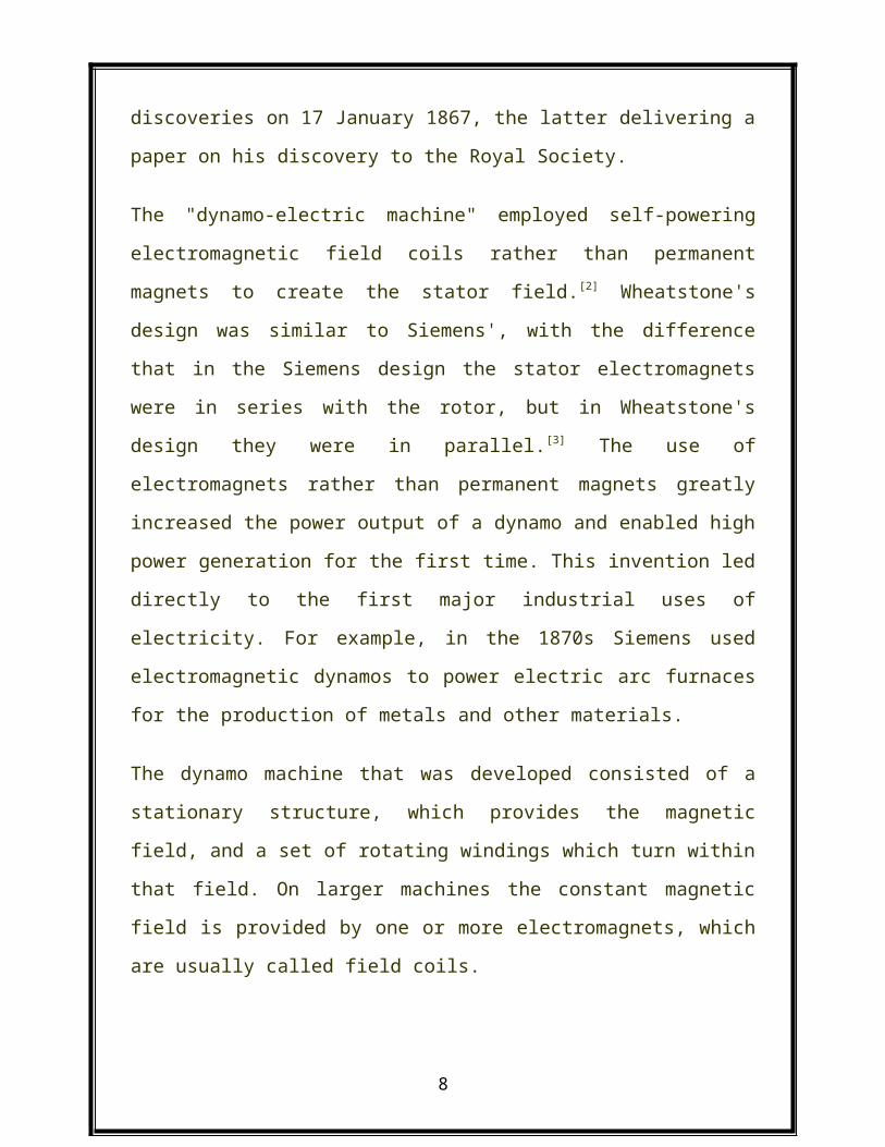
Wheatstone both announced their discoveries on 17 January 1867, the latter
delivering a paper on his discovery to the Royal Society.
5

The "dynamo-electric machine" employed self-powering electromagnetic field
coils rather than permanent magnets to create the stator field. [2] Wheatstone's
design was similar to Siemens', with the difference that in the Siemens design the
stator electromagnets were in series with the rotor, but in Wheatstone's design
they were in parallel.[3] The use of electromagnets rather than permanent
magnets greatly increased the power output of a dynamo and enabled high
power generation for the first time. This invention led directly to the first major
industrial uses of electricity. For example, in the 1870s Siemens used
electromagnetic dynamos to power electric arc furnaces for the production of
metals and other materials.
The dynamo machine that was developed consisted of a stationary structure,
which provides the magnetic field, and a set of rotating windings which turn
within that field. On larger machines the constant magnetic field is provided by
one or more electromagnets, which are usually called field coils.
Large power generation dynamos are now rarely seen due to the now nearly universal
use of alternating current for power distribution. Before the adoption of AC, very large
direct-current dynamos were the only means of power generation and distribution. AC
has come to dominate due to the ability of AC to be easily transformed to and from
very high voltages to permit low losses over large distances.
Alternating current generators
Ferranti alternating current generator, c. 1900.
6

Through a series of discoveries, the dynamo was succeeded by many later
inventions, especially the AC alternator, which was capable of generating
alternating current.
Alternating current generating systems were known in simple forms from
Michael Faraday's original discovery of the magnetic induction of electric current.
Faraday himself built an early alternator. His machine was a "rotating rectangle",
whose operation was heteropolar - each active conductor passed successively
through regions where the magnetic field was in opposite directions.[4]
Large two-phase alternating current generators were built by a British electrician,
J.E.H. Gordon, in 1882. The first public demonstration of an "alternator system"
was given by William Stanley, Jr., an employee of Westinghouse Electric in 1886.[5]
Sebastian Ziani de Ferranti established Ferranti, Thompson and Ince in 1882, to
market his Ferranti-Thompson Alternator, invented with the help of renowned
physicist Lord Kelvin.[6] His early alternators produced frequencies between 100
and 300 Hz. Ferranti went on to design the Deptford Power Station for the
London Electric Supply Corporation in 1887 using an alternating current system.
On its completion in 1891, it was the first truly modern power station, supplying
high-voltage AC power that was then "stepped down" for consumer use on each
street. This basic system remains in use today around the world.
7
A small early 1900s 75 kVA direct-driven power station AC alternator, with a
separate belt-driven exciter generator.
In 1891, Nikola Tesla patented a practical "high-frequency" alternator (which
operated around 15 kHz).[7] After 1891, polyphase alternators were introduced to
supply currents of multiple differing phases.[8] Later alternators were designed for
varying alternating-current frequencies between sixteen and about one hundred
hertz, for use with arc lighting, incandescent lighting and electric motors.[9]
Self-excitation
As the requirements for larger scale power generation increased, a new
limitation rose: the magnetic fields available from permanent magnets. Diverting
a small amount of the power generated by the generator to an electromagnetic
field coil allowed the generator to produce substantially more power. This
concept was dubbed self-excitation.
The field coils are connected in series or parallel with the armature winding.
When the generator first starts to turn, the small amount of remanent
magnetism present in the iron core provides a magnetic field to get it started,
generating a small current in the armature. This flows through the field coils,
creating a larger magnetic field which generates a larger armature current. This
"bootstrap" process continues until the magnetic field in the core levels off due
to saturation and the generator reaches a steady state power output.
Very large power station generators often utilize a separate smaller generator to
excite the field coils of the larger. In the event of a severe widespread power
outage where islanding of power stations has occurred, the stations may need to
8

perform a black start to excite the fields of their largest generators, in order to
restore customer power service.[10]
Specialized types of generator
Direct current
Homopolar generator
A homopolar generator is a DC electrical generator comprising an electrically
conductive disc or cylinder rotating in a plane perpendicular to a uniform static
magnetic field. A potential difference is created between the center of the disc
and the rim (or ends of the cylinder), the electrical polarity depending on the
direction of rotation and the orientation of the field.
It is also known as a unipolar generator, acyclic generator, disk dynamo, or
Faraday disc. The voltage is typically low, on the order of a few volts in the case
of small demonstration models, but large research generators can produce
hundreds of volts, and some systems have multiple generators in series to
produce an even larger voltage.[11] They are unusual in that they can produce
tremendous electric current, some more than a million amperes, because the
homopolar generator can be made to have very low internal resistance.
MHD generator
A magnetohydrodynamic generator directly extracts electric power from moving
hot gases through a magnetic field, without the use of rotating electromagnetic
machinery. MHD generators were originally developed because the output of a
9

plasma MHD generator is a flame, well able to heat the boilers of a steam power
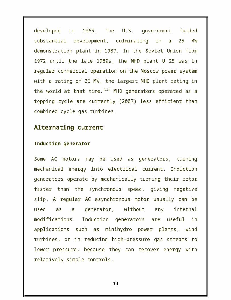
plant. The first practical design was the AVCO Mk. 25, developed in 1965. The
U.S. government funded substantial development, culminating in a 25 MW
demonstration plant in 1987. In the Soviet Union from 1972 until the late 1980s,
the MHD plant U 25 was in regular commercial operation on the Moscow power
system with a rating of 25 MW, the largest MHD plant rating in the world at that
time.[12] MHD generators operated as a topping cycle are currently (2007) less
efficient than combined cycle gas turbines.
Alternating current
Induction generator
Some AC motors may be used as generators, turning mechanical energy into
electrical current. Induction generators operate by mechanically turning their
rotor faster than the synchronous speed, giving negative slip. A regular AC
asynchronous motor usually can be used as a generator, without any internal
modifications. Induction generators are useful in applications such as minihydro
power plants, wind turbines, or in reducing high-pressure gas streams to lower
pressure, because they can recover energy with relatively simple controls.
To operate an induction generator must be excited with a leading voltage; this is
usually done by connection to an electrical grid, or sometimes they are self-
excited by using phase correcting capacitors.
Linear electric generator
In the simplest form of linear electric generator, a sliding magnet moves back and
forth through a solenoid - a spool of copper wire. An alternating current is
10

induced in the loops of wire by Faraday's law of induction each time the magnet
slides through. This type of generator is used in the Faraday flashlight. Larger
linear electricity generators are used in wave power schemes.
Variable speed constant frequency generators
Many renewable energy efforts attempt to harvest natural sources of mechanical
energy (wind, tides, etc) to produce electricity. Because these sources fluctuate in
power applied, standard generators using permanent magnets and fixed
windings would deliver unregulated voltage and frequency. The overhead of
regulation (whether before the generator via gear reduction or after generation
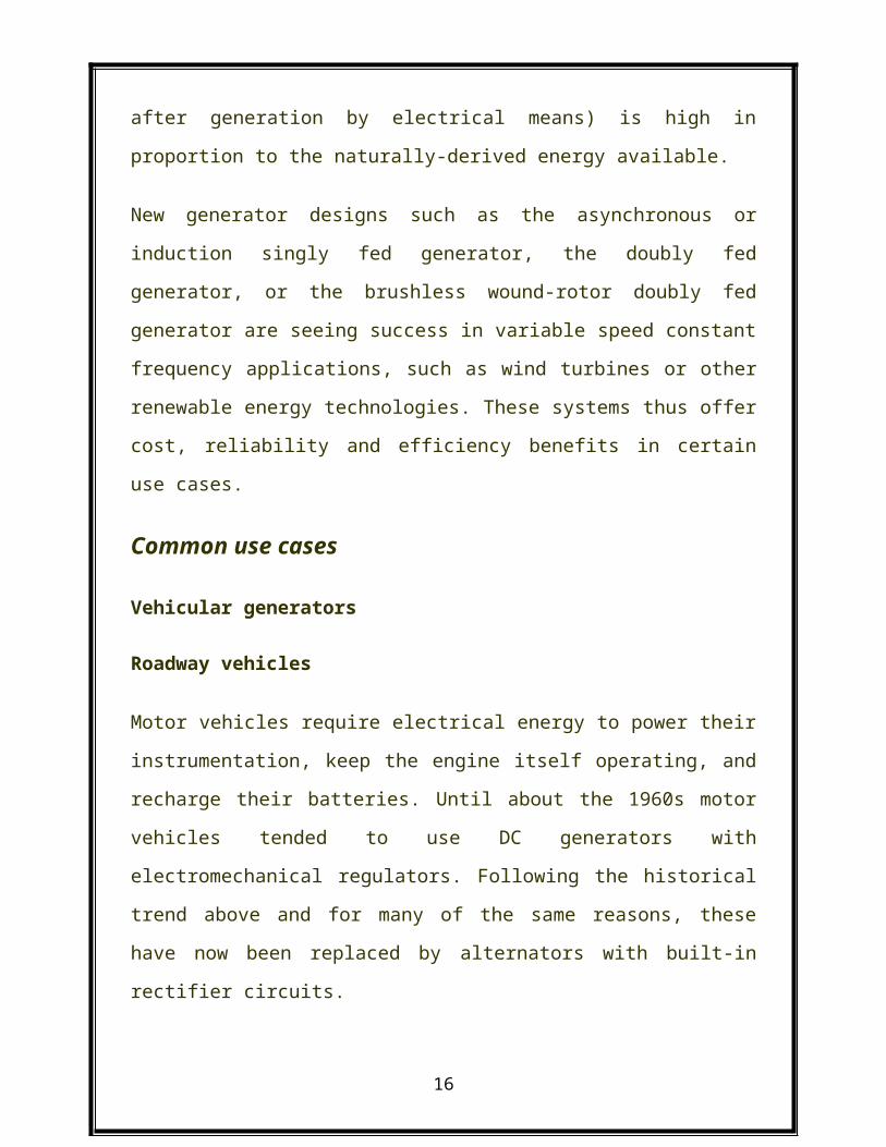
by electrical means) is high in proportion to the naturally-derived energy
available.
New generator designs such as the asynchronous or induction singly fed
generator, the doubly fed generator, or the brushless wound-rotor doubly fed
generator are seeing success in variable speed constant frequency applications,
such as wind turbines or other renewable energy technologies. These systems
thus offer cost, reliability and efficiency benefits in certain use cases.
Common use cases
Vehicular generators
Roadway vehicles
Motor vehicles require electrical energy to power their instrumentation, keep the
engine itself operating, and recharge their batteries. Until about the 1960s motor
vehicles tended to use DC generators with electromechanical regulators.
11

Following the historical trend above and for many of the same reasons, these
have now been replaced by alternators with built-in rectifier circuits.
Bicycles
Bicycles require energy to power running lights and other equipment. There are
two common kinds of generator in use on bicycles: bottle dynamos which engage
the bicycle's tire on an as-needed basis, and hub dynamos which are directly
attached to the bicycle's drive train.
Sailboats
Sailing boats may use a water- or wind-powered generator to trickle-charge the
batteries. A small propeller, wind turbine or impeller is connected to a low-power
generator to supply currents at typical wind or cruising speeds.
Genset
The Caterpillar 3512C Genset is an example of the engine-generator package.
This unit produces 1225 kilowatts of electric power.
An engine-generator is the combination of an electrical generator and an engine
(prime mover) mounted together to form a single piece of self-contained
equipment. The engines used are usually piston engines, but gas turbines can
also be used. And there are even hybrid diesel-gas units, called dual-fuel units.
12

Many different versions of engine-generators are available - ranging from very
small portable petrol powered sets to large turbine installations. The primary
advantage of engine-generators is the ability to independently supply electricity,
allowing the units to serve as backup power solutions.[13]
Human powered electrical generators
A generator can also be driven by human muscle power (for instance, in field
radio station equipment).
Protesters at Occupy Wall Street using bicycles connected to a motor and one-
way diode to charge batteries for their electronics[14]
Human powered direct current generators are commercially available, and have
been the project of some DIY enthusiasts. Typically operated by means of pedal
power, a converted bicycle trainer, or a foot pump, such generators can be
practically used to charge batteries, and in some cases are designed with an
integral inverter. The average adult could generate about 125-200 watts on a
pedal powered generator, but at a power of 200 W, a typical healthy human will
reach complete exhaustion and fail to produce any more power after
approximately 1.3 hours.[15] Portable radio receivers with a crank are made to
reduce battery purchase requirements, see clockwork radio. During the mid 20th
century, pedal powered radios were used throughout the Australian outback, to
13
provide schooling (School of the Air), medical and other needs in remote stations
and towns.
Mechanical measurement
Designed to measure shaft speed, a tachogenerator is a device which produces
an output voltage proportional to that speed. Tachogenerators are frequently
used to power tachometers to measure the speeds of electric motors, engines,
and the equipment they power. speed. With precise construction and design,
generators can be built to produce very precise voltages for certain ranges of
shaft speeds.[citation needed]
Equivalent circuit
Equivalent circuit of generator and load.
G = generator
VG=generator open-circuit voltage
RG=generator internal resistance
VL=generator on-load voltage
RL=load resistance
An equivalent circuit of a generator and load is shown in the diagram to the right.
The generator is represented by an abstract generator consisting of an ideal
voltage source and an internal resistance. The generator's and parameters
can be determined by measuring the winding resistance (corrected to operating
14

temperature), and measuring the open-circuit and loaded voltage for a defined
current load.
This is the simplest model of a generator, further elements may need to be added
for an accurate representation. In particular, inductance can be added to allow
for the machine's windings and magnetic leakage flux,[16] but a full representation
can become much more complex than this.[17]
How to Make a Simple Electric Generator
Building a simple, low powered electric generator can be a fun science fair project, or
just a workshop experiment for a would-be engineer. The parts are simple, inexpensive,
and easy to find.
== Steps ==
1. Decide how large a project you are interested in building. There are design
and engineering considerations that could be taken up, but for simplicity's
sake, this article will give instructions for a simple, low output generator.
2. Acquire the materials you will need. The sizes and specifications can be
adjusted to raise the output capacity of your generator, but this is a basic
overview of the project.
o 22-28 ga. enameled copper wire. About 500 feet (152.4 m) will
produce a modest electrical current. More "windings", coupled with
a stronger magnet will increase the power output.
15
o 3 or 4 inch (7.6 or 10.2 cm) bar magnet. (Should fit lengthwise in
the cardboard tube, below, with a little clearance)
o 1⁄4 inch (0.6 cm) diameter steel or aluminum rod, 12 inches
(30.5 cm) in length.
o 24 inches (61.0 cm) of 1X4 lumber.
o 1 - large paper or card board tube, 4-inch (10-cm) diameter.
o 2 - 1/4 inch (5.7 cm) flat washers.
3. Build a "U" shaped frame to support your "rotor", ie, the permanent bar
magnet mounted on a steel shaft. by
o Cut the 1X4 lumber into pieces, 2, at 6 inch (15.2 cm) lengths, one
at 12 inches (30.5 cm) in length.
o Nail or screw the two 6 inch (15.2 cm) boards to the 12 inch
(30.5 cm) board at a perpendicular angle to the 12 inch (30.5 cm)
board, which is the base for the rotor frame.
4. Drill two 1⁄4 inch (0.6 cm) holes in the two uprights of your frame, aligning
them so that the 1⁄4 inch (0.6 cm) rod, (the rotor shaft) will go through
both without binding.
5. Drill a 1⁄4 inch (0.6 cm) hole through the center of your bar magnet, on the
flat, or widest side. Be careful to measure the center both in length and
width, and drill perpendicularly, so that when the shaft goes through, the
magnet will be "square" to the shaft.
6. Slide the metal shaft through one side of the support frame, slide the
magnet onto the shaft.
7. Cut a 4 inch (10.2 cm) section of the paper or cardboard tube. If you don't
have a piece of tubing available, you can make one by rolling a sheet of
construction paper into a cylinder and gluing or taping it to secure it in this
shape. The ideal diameter of the tube will be just large enough to allow
16

the bar magnet to spin freely inside the tube, keeping the magnetic field
as near the copper windings as possible.
8. Wind the copper wire around the cardboard or paper tube, leaving about
16 to 18 inches (40.6 to 45.7 cm) of wire loose on each end to connect to
you power test device, an electric light bulb, or other device you will
supply power to. The more "turns" or winds around the tube you make,
the more power your generator should produce.
9. Slide the tube over the shaft and magnet, then slide the shaft on through
the other support frame. You will want several inches of the shaft sticking
through each end of the frame.
10. Glue the magnet to the shaft at the center of the two supports, using a
high strength hot melt glue or epoxy. You may choose to drill and tap
threads into the magnet for a "set screw" if you have the tools to do so,
but the idea is for the magnet to be stationary in relation to the shaft.
11. Support the paper cylinder with the wire windings at the center of the
shaft with the bar magnet centered on the wire windings. You may simply
cut cardboard legs that can be glued to the cylinder, or build a wire frame
from a coat hanger or similar stiff wire to accomplish this.
12. Turn the shaft with your fingers to see if the ends of the magnet hit the
inside of the tube. It must turn freely, but be as close as possible to the
tube. Again, having the magnet's ends as close the copper wire windings
will increase the "exciting" action of the magnetic fields the magnet
produces.
13. Glue a washer on each end of the shaft outside the wood supports.
14. Attach the two wires you have loose at the ends of the windings to a
flashlight bulb or other low voltage lamp, or connect the test leads from a
voltmeter or multimeter to them.
17

15. Spin the shaft as fast as possible. You may want to wind a string around
the end of the shaft as you would a toy "top", then pull it sharply, or just
spin it with your fingers. You should get a small voltage, enough to light a
1.5 volt light bulb by manually spinning the shaft.
Electric power transmission:-
Electric-power transmission is the bulk transfer of electrical energy, from
generating power plants to electrical substations located near demand centers.
This is distinct from the local wiring between high-voltage substations and
customers, which is typically referred to as electric power distribution.
Transmission lines, when interconnected with each other, become transmission
networks. The combined transmission and distribution network is known as the
"power grid" in the United States, or just "the grid". In the United Kingdom, the
network is known as the "National Grid".
A wide area synchronous grid, also known as an "interconnection" in North
America, directly connects a large number of generators delivering AC power
with the same relative phase, to a large number of consumers. For example,
there are four major interconnections in North America (the Western
Interconnection, the Eastern Interconnection, the Quebec Interconnection and
the Electric Reliability Council of Texas (ERCOT) grid), and one large grid for most
of continental Europe.
Historically, transmission and distribution lines were owned by the same
company, but starting in the 1990s, many countries have liberalized the
regulation of the electricity market in ways that have led to the separation of the
electricity transmission business from the distribution business.[1]
18

System
Most transmission lines are high-voltage three-phase alternating current (AC),
although single phase AC is sometimes used in railway electrification systems.
High-voltage direct-current (HVDC) technology is used for greater efficiency at
very long distances (typically hundreds of miles (kilometers)), or in submarine
power cables (typically longer than 30 miles (50 km)).[citation needed] HVDC links are
also used to stabilize and control problems in large power distribution networks
where sudden new loads or blackouts in one part of a network can otherwise
result in synchronization problems and cascading failures.
Diagram of an electric power system; transmission system is in blue
Electricity is transmitted at high voltages (120 kV or above) to reduce the energy
losses in long-distance transmission. Power is usually transmitted through
overhead power lines. Underground power transmission has a significantly higher
cost and greater operational limitations but is sometimes used in urban areas or
sensitive locations.[citation needed]
A key limitation of electric power is that, with minor exceptions, electrical energy
cannot be stored, and therefore must be generated as needed.[citation needed] A
sophisticated control system is required to ensure electric generation very closely
matches the demand.
19

References
1. "A Primer on Electric Utilities, Deregulation, and Restructuring of U.S.
Electricity Markets" (pdf). United States Department of Energy Federal
Energy Management Program (FEMP). May 2002. Retrieved December
27, 2008.
2. Hans Dieter Betz, Ulrich Schumann, Pierre Laroche (2009). Lightning:
Principles, Instruments and Applications. Springer, pp. 202–203. ISBN
978-1-4020-9078-3. Retrieved on May 13, 2009.
3. Thomas P. Hughes (1993). Networks of Power: Electrification in Western
Society, 1880–1930. Baltimore: Johns Hopkins University Press. pp. 119–
122. ISBN 0-8018-4614-5.
4. National Council on Electricity Policy. "Electricity Transmission: A
primer" (pdf).
5. Bureau of Census data reprinted in Hughes, pp. 282–283
6. Hughes, pp. 293–295
7. Paris, L.; Zini, G.; Valtorta, M.; Manzoni, G.; Invernizzi, A.; De Franco,
N.; Vian, A. (1984). "Present Limits of Very Long Distance Transmission
Systems" (pdf). CIGRE International Conference on Large High Voltage
Electric Systems, 1984 Session, 29th August-6th September. Global
Energy Network Institute. Retrieved March 29, 2011. 4.98 MB
8. "NYISO Zone Maps". New York Independent System Operator. Retrieved
January 10, 2014.
9. American Electric Power, Transmission Facts, page 4:
http://www.aep.com/about/transmission/docs/transmission-facts.pdf
10. California Public Utilities Commission Corona and induced currents
11. "Where can I find data on electricity transmission and distribution
losses?". Frequently Asked Questions – Electricity. U.S. Energy
Information Administration. November 19, 2009. Retrieved March 29,
2011.
12. Donald G. Fink and H. Wayne Beaty, Standard Handbook for Electrical
Engineers (15th Edition) McGraw-Hill, 2007 ISBN 978-0-07-144146-9
section 18.5
20

Conclusion & Summary
The "dynamo-electric machine" employed self-powering electromagnetic field
coils rather than permanent magnets to create the stator field. [2] Wheatstone's
design was similar to Siemens', with the difference that in the Siemens design the
stator electromagnets were in series with the rotor, but in Wheatstone's design
they were in parallel.[3] The use of electromagnets rather than permanent
magnets greatly increased the power output of a dynamo and enabled high
power generation for the first time. This invention led directly to the first major
industrial uses of electricity. For example, in the 1870s Siemens used
electromagnetic dynamos to power electric arc furnaces for the production of
metals and other materials.
The dynamo machine that was developed consisted of a stationary structure,
which provides the magnetic field, and a set of rotating windings which turn
within that field. On larger machines the constant magnetic field is provided by
one or more electromagnets, which are usually called field coils.
21