Electric field induced semiconductor-to-metal phase ...
29
Electric field induced semiconductor-to-metal phase transition in vertical MoTe 2 and Mo 1-x W x Te 2 devices Feng Zhang 1,2 , Sergiy Krylyuk 4,5 , Huairuo Zhang 4,5* , Cory A. Milligan 1,3 , Dmitry Y. Zemlyanov 1 , Leonid A. Bendersky 5 , Albert V. Davydov 5 and Joerg Appenzeller 1,2* 1 Birck Nanotechnology Center, Purdue University, West Lafayette, Indiana 47907, USA. 2 Department of Electrical and Computer Engineering, Purdue University, West Lafayette, Indiana 47907, USA. 3 School of Chemical Engineering, Purdue University, West Lafayette, Indiana 47907, USA. 4 Theiss Research, Inc., La Jolla, California 92037, USA. 5 Materials Science and Engineering Division, National Institute of Standards and Technology (NIST), Gaithersburg, Maryland 20899, USA. * Corresponding Authors: [email protected] (J.A.); [email protected] (H.Z.) Abstract Over the past years, transition metal dichalcogenides (TMDs) have attracted attention as potential building blocks for various electronic applications due to their atomically thin nature. An exciting development is the recent success in “engineering” crystal phases of TMD compounds during the growth due to their polymorphic character. Here, we report an electric field induced reversible engineered phase transition in vertical 2H-MoTe 2 devices, a crucial experimental finding that enables electrical phase switching for these ultra-thin layered materials. Scanning tunneling microscopy (STM) was utilized to analyze the TMD crystalline structure after applying an electric field, and scanning tunneling spectroscopy (STS) was employed to map a semiconductor-to-metal phase transition on the nanoscale. In addition, direct confirmation of a phase transition from 2H semiconductor to a distorted 2H metallic phase was obtained by scanning transmission electron microscopy (STEM). MoTe 2 and Mo 1-x W x Te 2 alloy based vertical resistive random access memory (RRAM) cells were fabricated to demonstrate clear reproducible and controlled switching with programming voltages that are tunable by the layer thickness and that show a distinctly different trend for the binary compound if compared to the ternary materials. Main text Many applications such as memristors 1 , micro-motors 2 , electronic oscillators 3 , and sensors 4 greatly benefit from recent trends in the area of “phase engineering”. The most prominent materials that are explored in this context are VO 2 and NbO 2 which can both undergo a Mott metal-to-insulator transition 5 and amorphous-to-crystalline phase change materials as Ge 2 Sb 2 Te 5 6 . Recently, transition metal dichalcogenides (TMDs) attracted considerable attention in the field of 2D phase engineering due to their polymorphic character. TMDs exist in various crystalline
Transcript of Electric field induced semiconductor-to-metal phase ...

Electric field induced semiconductor-to-metal phase transition in vertical
MoTe2 and Mo1-xWxTe2 devices
Feng Zhang1,2
, Sergiy Krylyuk4,5
, Huairuo Zhang4,5*
, Cory A. Milligan1,3
, Dmitry Y. Zemlyanov1,
Leonid A. Bendersky5, Albert V. Davydov
5 and Joerg Appenzeller
1,2*
1Birck Nanotechnology Center, Purdue University, West Lafayette, Indiana 47907, USA.
2Department of Electrical and Computer Engineering, Purdue University, West Lafayette,
Indiana 47907, USA. 3School of Chemical Engineering, Purdue University, West Lafayette, Indiana 47907, USA.
4Theiss Research, Inc., La Jolla, California 92037, USA.
5Materials Science and Engineering Division, National Institute of Standards and Technology
(NIST), Gaithersburg, Maryland 20899, USA.
*Corresponding Authors: [email protected] (J.A.); [email protected] (H.Z.)
Abstract
Over the past years, transition metal dichalcogenides (TMDs) have attracted attention as
potential building blocks for various electronic applications due to their atomically thin nature.
An exciting development is the recent success in “engineering” crystal phases of TMD
compounds during the growth due to their polymorphic character. Here, we report an electric
field induced reversible engineered phase transition in vertical 2H-MoTe2 devices, a crucial
experimental finding that enables electrical phase switching for these ultra-thin layered materials.
Scanning tunneling microscopy (STM) was utilized to analyze the TMD crystalline structure
after applying an electric field, and scanning tunneling spectroscopy (STS) was employed to map
a semiconductor-to-metal phase transition on the nanoscale. In addition, direct confirmation of a
phase transition from 2H semiconductor to a distorted 2H metallic phase was obtained by
scanning transmission electron microscopy (STEM). MoTe2 and Mo1-xWxTe2 alloy based vertical
resistive random access memory (RRAM) cells were fabricated to demonstrate clear
reproducible and controlled switching with programming voltages that are tunable by the layer
thickness and that show a distinctly different trend for the binary compound if compared to the
ternary materials.
Main text
Many applications such as memristors1, micro-motors
2, electronic oscillators
3, and sensors
4
greatly benefit from recent trends in the area of “phase engineering”. The most prominent
materials that are explored in this context are VO2 and NbO2 which can both undergo a Mott
metal-to-insulator transition5 and amorphous-to-crystalline phase change materials as Ge2Sb2Te5
6.
Recently, transition metal dichalcogenides (TMDs) attracted considerable attention in the field of
2D phase engineering due to their polymorphic character. TMDs exist in various crystalline

phases which exhibit semiconducting, semimetallic and metallic properties. In particular,
experimental phase diagram data and density functional theory (DFT) calculations indicate that
the most thermodynamically stable phase at room-temperature for molybdenum and tungsten
containing dichalcogenides is the semiconducting hexagonal (2H) phase, with the exception of
WTe2, for which the metallic octahedral (Td) crystal structure is stable at standard conditions.
However, since for some TMD compounds the energetic difference between the various phases
is rather moderate7,8
, several groups are working on phase engineering of TMDs. For example,
Py et al.9 demonstrated a 2H to 1T phase transition in MoS2 through the intercalation of lithium
and Liu et al.10
introduced an in-situ phase transition in MoS2 by means of electron beam
irradiation. However, MoS2 might not be the ideal candidate for TMD phase engineering. Due to
a very low energy difference between the metallic (1T) and the semiconducting (2H) phase of
MoTe2, it is considered the most promising TMD material for phase engineered applications7,8
.
Experimental results on MoTe2 include strain-induced semiconductor-to-metal transitions in
MoTe2 at room temperature11
and growth controlled transformations between the 1T and 2H
phase by means of tellurization rate12
and temperature control13,14
. Moreover, Empante et al.15
recently demonstrated three distinct structural phases (2H, 1T and 1T) in MoTe2 when
employing chemical vapor deposition (CVD) with controlled quenching. However, device
compatible methods to switch between the different phases in MoTe2 have yet to be reported.
Ultimately, for device applications, controlling the phase of a TMD by means of an electric field
and introducing a semiconductor-to-metal phase transition in this way is most desirable. Here we
demonstrate experimentally an electric field induced reversible semiconductor-to-metal phase
transition in vertical 2H-MoTe2 and 2H-Mo1-xWxTe2 devices. Scanning tunneling microscopy
(STM) was carried out to evaluate the structural impact of the electric field and scanning
tunneling spectroscopy (STS) was utilized to unambiguously demonstrate the localized
semiconductor-to-metal phase transition. Scanning transmission electron microscopy (STEM)
showed that a distorted metallic 2H phase formed in 2H-MoTe2 and 2H-Mo1-xWxTe2 based
RRAM devices that consist of a sandwich structure of TMD layers between metal electrodes
after electric field application. RRAM cells with areas in the 0.1 m2 range displayed set
voltages that are approximately linearly proportional to the flake thickness.
2H-MoTe2 and 2H-Mo1-xWxTe2 based RRAM
Fig. 1(a) shows a schematic as well as optical and SEM images of a typical vertical TMD RRAM
device under investigation. Top contact areas are approximately 0.1 m2. Our device design
ensures that only vertical transport occurs from one to the other electrode without any lateral
transport contributions. Because of the large aspect ratio between the top contact area and the
flake thickness, spreading resistance contributions can be ignored and the active device area is
identical to the top contact area. Area normalized I-V curves of exemplary vertical MoTe2, WSe2
and MoS2 devices are shown in Fig. 1(b). For all measurements in this article the bottom
electrode was grounded. Experimental current densities follow the expected trend with thickness,
i.e. higher current densities are observed for thinner flakes. The trend of higher current levels for

MoS2 if compared to MoTe2 and WSe2 is in qualitative agreement with our findings on the
height of Schottky barriers (SBs) in lateral devices from the same materials16
. Device
characteristics are reproducible and do not change substantially after multiple scans between -1
V and 1 V.
The situation however changes when the voltage range is extended. Vertical TMD devices from
MoTe2 and WSe2 can transition into a low resistive state (LRS) as illustrated in Fig. 1(c) and (d)
at a set voltage (here VSET = 2.3 V for MoTe2) that depends on the flake thickness. The details on
the forming process are provided in the Supplementary Material, where Fig. S1 (a) and (b) show
characteristic I-V curves for 10 nm and 15 nm thick MoTe2 flakes, respectively. After the
forming event, device characteristics can be cycled to exhibit typical bipolar RRAM type of
behavior in terms of: a) remaining in their LRS when no voltage is applied, b) preserving the low
resistive state over an appreciable voltage range until a sufficient reset voltage (here VRESET = -
1.5 V) of polarity opposite to the set voltage is reached, and c) remaining in their respective high
resistive state (HRS) until the set voltage is reached. Note that after the forming has occurred
(black symbols in Fig. 1(c)) the HRS always remains more conductive than the original state of
the device (red symbol in Fig. 1(c)) indicating that a permanent electronic change has occurred in
the device. For the case displayed in Fig. 1(c), the current ratio between the HRS and the LRS is
about 50 when the compliance is set to 400 A.
Compared to the behavior of MoTe2, the RRAM effect in WSe2 devices is much smaller. A
stable LRS and HRS is achieved after forming, where the switching characteristics (see red and
blue arrows in Fig. 1(d)) are consistent with the expected RRAM behavior and inconsistent with
simple hysteresis effects. However, switching between the HRS and LRS is not abrupt, making
WSe2 a poor candidate for RRAM applications.
For vertical MoS2 devices we never observed any RRAM effect for “clean devices”. Note that
any fabrication of RRAM devices as described here holds the risk of contamination of the
bottom electrode-to-TMD and TMD-to-top electrode interface. In a number of instances when
device characteristics did not show the expected current levels, e.g., in case of MoS2 gave rise to
current densities well below 104
A/cm2 at 1 V before forming for flake thicknesses below 25 nm,
some changes in the device resistance can be observed that may be interpreted as RRAM
behavior. However, these effects are not reproducible among devices and are likely related to the
forming of filaments in an unintentionally formed oxide layer at the electrode/TMD interface.
Once the intrinsic vertical current levels over 104
A/cm2 were reached in MoS2, no RRAM
behavior was observed in those devices.
In order to further explore the switching mechanism in TMDs, exfoliated MoTe2 based RRAM
cells with thicknesses between 6 nm and 36 nm were fabricated. All cells were nonvolatile and
stable. As an example, Fig. S2(b) shows read disturb measurements on a representative MoTe2
device. Before the forming process, the current per unit area through the vertical structures scales
approximately with the flake thickness (see Fig. 1(b)). However, once the system transitions into

its LRS, current levels (below the compliance) occur to be rather similar and do not show any
coherent scaling trend with the flake thickness or active device area. This statement is consistent
with the notion that the formation of conductive filaments that enable the LRS is not uniform but
gives rise to local current paths. For flake thicknesses from 6 nm to 36 nm, the set voltages can
be tuned from 0.9 V to 2.3 V (see Fig. 2(a) and (c)), corresponding to moderate fields in the
1MV/cm range. Noteworthy, the RRAM behavior was independent of the contact metal used.
For example, employing Ni instead of Ti/Ni as top electrode resulted in the same RRAM
performance as reported here.
Next, we explore the impact of the material preparation and composition on RRAM
characteristics by extending experiments to 2H-MoTe2 obtained using different approaches and
further to 2H-Mo1-xWxTe2 alloys. Similar switching characteristics of MoTe2 devices fabricated
using either commercial material or crystals synthesized in this work using different
temperatures and transport agents (see Materials and Methods) indicate that the observed RRAM
effect is not related to the processing conditions (Fig. 2(c)). Mo1-xWxTe2 devices exhibit very
similar switching behavior and their characteristics also depend monotonically on the flake
thickness (see Figs. 2(b) and (c)). However, while we are currently unable to resolve a
quantitative trend of the set voltages as a function of W-content, the set voltages for the Mo1-
xWxTe2 alloys show a tendency of being smaller than for the MoTe2 devices (see Fig. 2(c)),
implying that the critical electric field needed to trigger the RRAM behavior may have been
reduced in alloys. DFT calculations8,17,18
and recent experimental results19
suggest that
substitution of Mo by W in MoTe2 and creation of a Mo1-xWxTe2 alloys reduces the energy
difference between 2H and 1T' phases, which in turn should reduce the set voltages of Mo1-
xWxTe2 RRAM devices as compared with their MoTe2 counterparts. We believe that Fig. 2(c)
shows a first experimental evidence of this trend.
Electric field induced semiconductor-to-metal transition
In general, the electroforming process in RRAM devices aims at creating a conductive filament
by applying a sufficiently high electrical bias, which in turn results in an electric field and Joule
heating inside the sample. Both, the field and the heating can result in the formation of
conductive filaments that define the LRS while the HRS is characterized by the absence of these
filaments20
. In order to confirm the formation of conductive filaments in the case of MoTe2
RRAM cells, conductive AFM (C-AFM) measurements were carried out. First, a fully functional
MoTe2 device was biased to form the LRS, and then wet chemical etching as described in the
Supplemental Information section S9 was used to remove the top electrode. This approach
allows access to the TMD surface after the presumed filament formation to perform a local
analysis of the surface resistivity after the forming process had occurred. As shown in inset of
Fig. 3(a) by the arrow, a bright spot of ~ 80 nm in diameter, which was formerly covered by the
top electrode (red marked rectangle), is indicative of a current path through the TMD. For
comparison, those MoTe2 flakes that did not undergo a forming process show a uniform, highly
resistive surface (see Fig. 3(b)).

In order to explore the filament formation mechanism in case of MoTe2, STM was used to
perform a detailed surface analysis at room temperature. Fig. 3(c) shows a representative STM
image of the pristine exfoliated MoTe2 flake. The atomic surface structure of the 2H-phase of the
MoTe2 single crystal demonstrates the expected C3 symmetry with an interatomic distance of
0.34 nm. Imaging was performed with a bias voltage of -0.9 V. To mimic the situation in MoTe2
RRAM cells under forming conditions, a bias of -3 V was applied to a contact underneath the
TMD relative to the STM tip while scanning. Next, an STM image was taken again at a bias of -
0.9 V. As apparent from Fig. 3(d) the surface image appears drastically different after voltage
application, and non-uniform bright regions are clearly visible in the figure. A corrugation
profile measured along the bright region is shown in Fig. S4(c). „Protrusions‟ with a height of 0.3
nm to 0.6 nm on the sample surface are clearly observed, which are interpreted as possible
topographic changes in conjunction with changes in the local density of states (LDOS) (see
discussion below). Next, scanning tunneling spectroscopy (STS) measurements were performed
at four distinct locations as marked by the colored squares 1 through 4 in Fig. 3(d). Locations 1
and 2 fall into the region of alteration while 3 and 4 are located in the unperturbed region of the
sample that we will label as “pristine” in the following discussion. Fig. 3(e) shows the obtained
I-V characteristics at the four locations. Higher current levels in particular for small applied
voltages are observed for locations 1 and 2 (the modified areas) if compared with 3 and 4
(pristine areas). The corresponding dI/dV curves shown in Fig. 3(f) are a measure of the local
density of states (LDOS). While characteristics obtained for the pristine areas (locations 3 and 4)
indicate the presence of a bandgap in the range of 0.85 eV, consistent with the extracted bandgap
of 2H-MoTe2 from electrical measurements16
, the LDOS of locations 1 and 2 shows a finite
density of states even at zero bias, implying that these regions had become metallic after a
forming voltage had been applied. At a first glance, the positions of atoms in the modified (red
circle) and the pristine (green circles) regions occur identical (C3 symmetry) as shown in the
zoom-in Fig. 3(d). However, by comparing the positions of atomic sites along the red and green
dashed lines, a clear distortion between tellurium atoms in the pristine and voltage disturbed
areas is apparent. The atomic rows of Te in the pristine and voltage modified areas are rotated
relative to each other by 3 to 6 as shown in Fig. 3(d) and S4(b). The same phenomenon is
observed when Mo0.96W0.04Te2 devices are analyzed by STM (see supplementary material
section S5 for details). Last, it is important to note that – like in the RRAM cell – metallic
features that were created by applying a voltage of -3 V can be turned semiconducting again by
applying a voltage of opposite polarity. Since the change of surface topography is highly non-
uniform however, it is at this stage not possible to unambiguously follow one particular STM
feature exclusively through the setting and resetting procedure. The sum of these observations
lead us to believe that MoTe2 undergoes a reversible phase transition from a semiconducting to a
metallic state under application of an electric field, which is responsible for the RRAM behavior
observed by us and reported here.
Next, it is worth asking the question whether any stable metallic phase is expected to exist in
MoTe2 that can be created by means of an electric field. Indeed, electrically induced phase

transitions were observed previously in TaSe221
and TaS222
. Moreover, DFT calculations 7
predict that the semiconducting 2H phase in MoTe2 is energetically different by only 31 meV per
formula unit from the semi-metallic monoclinic 1T phase, a value much smaller than for other
TMDs. While these facts speak potentially for an electrically induced 2H-to-1T phase transition,
one would expect to observe a rectangular surface unit-cell in the areas of the protrusions which
is characteristic for the 1T phase (see Fig. S7), while our STM image supports more a rotation of
the hexagonal 2H-MoTe2 surface cell between the pristine and the voltage modified areas. On
the other hand, the 1T phase is a modified 2H phase with distinct atomic shifts, and the
projected structures, e.g. of Te, on (001) for both 2H and 1T have rather similar lattice constants,
with a=3.52 Å for the 2H hexagonal phase and a=3.47 Å, b=6.33 Å for the 1T pseudo-hexagonal
phase. It is thus possible that the topographical changes hinted at above mask the clear
distinction between those two phases. An alternative explanation, involves an electrical field
induced local rotation of the topmost 2H-MoTe2 planes, resulting in the observed angle between
Te-rows in the pristine and modified areas as described above (see Fig. 3(d) and Fig. S4(b)).
Indeed, similarly rotated structures have been reported after electron irradiation of 2H-MoTe223
.
Since the atomic arrangement in the modified and the pristine regions occur similar as shown in
the zoom-in Fig. 3(d), we conclude at this stage that a metallic hexagonal 1T phase or a metallic
distorted 2H' phase has been created by applying an electric field.
To identify the exact nature of the observed field induced phase change further, scanning
transmission electron microscopy (STEM) of cross-sectional samples was utilized for both
MoTe2 and Mo1-xWxTe2 devices. Before performing the STEM analysis, RRAM devices
underwent the same forming process as described above to create filaments in the flakes. Fig.
4(a) shows a cross-sectional atomic-resolution high-angle annular dark field (HAADF)-STEM
image of a Mo0.96W0.04Te2 device. The RRAM multilayer structure is clearly visible from the
HAADF contrast (see also Fig. S8-1(b)). Note that the STEM image displays the TMD flake
both in the active Ni/Ti/Mo0.96W0.04Te2/Au/Ti/SiO2 (right) and non-active region (left) where an
SiO2 isolation layer on top of the TMD prevented RRAM operation. For all scans performed, we
observe that the non-active area only exhibited the original 2H phase of Mo0.96W0.04Te2. On the
other hand, in the active region, two structurally distinct domains are observed; the domains are
marked as 2H and 2H' in Fig. 4(b), which is a zoom-in HAADF image of the red-marked box in
(a). The 2H' region, delineated by the white dash-dotted lines, is about 80 nm wide (consistent
with the diameter of the filament measured by C-AFM) and extends vertically through the whole
Mo0.96W0.04Te2 flake. Fig. 4(c) of the 2H region shows an atomic HAADF image in [110]2H zone
axis with well-resolved atomic columns of Mo/W and Te. Fig. 4(d) shows a structural HAADF
image from the 2H' domain. Instead of the well-aligned atomic columns as observed for the 2H
structure, the atomic columns of the 2H' structure are not resolved in this orientation due to
apparent shift and splitting along the c-direction (The same transition occurs in the vertical
MoTe2 device as apparent from Fig. S8-1).
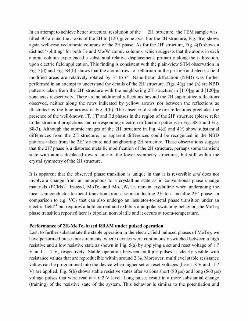
In an attempt to achieve better structural resolution of the 2H' structure, the TEM sample was
tilted 30 ̊ around the c-axis of the 2H to [120]2H zone axis. For the 2H structure, Fig. 4(e) shows
again well-resolved atomic columns of the 2H phase. As for the 2H' structure, Fig. 4(f) shows a
distinct „splitting‟ for both Te and Mo/W atomic columns, which suggests that the atoms in each
atomic column experienced a substantial relative displacement, primarily along the c-direction,
upon electric field application. This finding is consistent with the plain-view STM observation in
Fig. 3(d) and Fig. S4(b) shows that the atomic rows of tellurium in the pristine and electric field
modified areas are relatively rotated by 3 to 6. Nano-beam diffraction (NBD) was further
performed in an attempt to understand the details of the 2H' structure. Figs. 4(g) and (h) are NBD
patterns taken from the 2H' structure with the neighboring 2H structure in [110]2H and [120]2H
zone axes respectively. There are no additional reflections beyond the 2H superlattice reflections
observed, neither along the rows indicated by yellow arrows nor between the reflections as
illustrated by the blue arrows in Fig. 4(h). The absence of such extra-reflections precludes the
presence of the well-known 1T, 1T' and Td phases in the region of the 2H' structure (please refer
to the structural projections and corresponding electron diffraction patterns in Fig. S8-2 and Fig.
S8-3). Although the atomic images of the 2H' structure in Fig. 4(d) and 4(f) show substantial
differences from the 2H structure, no apparent differences could be recognized in the NBD
patterns taken from the 2H' structure and neighboring 2H structure. These observations suggest
that the 2H' phase is a distorted metallic modification of the 2H structure, perhaps some transient
state with atoms displaced toward one of the lower symmetry structures, but still within the
crystal symmetry of the 2H structure.
It is apparent that the observed phase transition is unique in that it is reversible and does not
involve a change from an amorphous to a crystalline state as in conventional phase change
materials (PCMs)6. Instead, MoTe2 and Mo1-xWxTe2 remain crystalline when undergoing the
local semiconductor-to-metal transition from a semiconducting 2H to a metallic 2H phase. In
comparison to e.g. VO2 that can also undergo an insulator-to-metal phase transition under an
electric field24
but requires a hold current and exhibits a unipolar switching behavior, the MoTe2
phase transition reported here is bipolar, nonvolatile and it occurs at room-temperature.
Performance of 2H-MoTe2 based RRAM under pulsed operation
Last, to further substantiate the stable operation in the electric field induced phases of MoTe2, we
have performed pulse-measurements, where devices were continuously switched between a high
resistive and a low resistive state as shown in Fig. 5(a) by applying a set and reset voltage of 1.7
V and -1.4 V, respectively. Stable operation between multiple pulses is clearly visible with
resistance values that are reproducible within around 2 %. Moreover, multilevel stable resistance
values can be programmed into the device when higher set or reset voltages (here 1.8 V and -1.7
V) are applied. Fig. 5(b) shows stable resistive states after various short (80 s) and long (560 s)
voltage pulses that were read at a 0.2 V level. Long pulses result in a more substantial change
(training) of the resistive state of the system. This behavior is similar to the potentiation and

depression of biological synapses and hints at yet another application space of this class of
vertical TMD devices in the realm of neuromorphic computing.
Summary
In this paper, an electric field induced reversible semiconductor (2H)-to-metal (2H) phase
transition in vertical 2H-MoTe2 and Mo1-xWxTe2 has been achieved experimentally. Conductive
filaments were created during electric field application as shown by C-AFM, STM, STS and
STEM measurements. Atomic resolution images support that a distorted metallic 2H phase is
created after voltage modification and that this crystalline phase is responsible for the observed
RRAM behavior in MoTe2 and Mo1-xWxTe2. Programming voltages are tunable by the MoTe2
flake thickness and partial substitution of Mo by W in MoTe2 reduces the critical electric field
for the phase transition in qualitative agreement with DFT calculations. Our work indicates the
possibility to locally and selectively engineer the phases in TMDs by electric fields, and
demonstrates the potential of TMDs for RRAM applications.
Materials and Methods25
Devices fabrication and electrical measurement
First a layer of Ti/Au (10 nm/25 nm) which acts as a bottom electrode was deposited onto a 90
nm silicon dioxide (SiO2) layer located on top of a highly doped silicon wafer. Next, TMD flakes
from either (i) MoTe2 (2D Semiconductors), (ii) WSe2 (HQ Graphene), (iii) MoS2 (SPI Supplies)
or (iv) Mo1-xWxTe2 (NIST) were exfoliated onto this electrode using standard scotch tape
techniques, followed by a thermal evaporation of 55 nm SiO2 acting as an insulating layer. The
device fabrication was finished by the definition of a Ti/Ni (35 nm/50 nm) top electrode.
Electrical characterization of the devices was performed at room-temperature using a parameter
analyzer (Agilent 4156C).
TMDs synthesis and characterization
Both 1T- and 2H-Mo1-xWxTe2 crystals (x = 0, 0.03, 0.04, 0.07, 0.09) were produced at NIST
using the Chemical Vapor Transport (CVT) method. First, polycrystalline Mo1-xWxTe2 powders
were synthesized by reacting stoichiometric amounts of molybdenum (99.999 %), tungsten (99.9
%) and tellurium (99.9 %) at 750 C in a vacuum-sealed quartz ampoule. Next, Mo1-xWxTe2
crystals were grown at 950 C to 1000 C using approximately 1 g of poly-Mo1-xWxTe2 charge
and a small amount of iodine (99.8 %, 5 mg/cm3) sealed in evacuated quartz ampoules. The
ampoules were ice-water quenched after 7 days of growth yielding Mo1-xWxTe2 crystals in the
metallic 1T phase. The 1T-MoTe2 (Mo1-xWxTe2, x 0) crystals were then converted to the
semiconducting 2H phase by annealing in vacuum-sealed ampoules at 950 C (750 C) for 24 h
(72 h) followed by cooling to room temperature at a 10 C/h rate. 2H-MoTe2 crystals were also
obtained by CVT growth at 800 C for 140 h using TeCl4 (99.9 %, 5.7 mg/cm3) as a transport
agent. At this temperature, MoTe2 crystals grow directly in the 2H phase and hence do not

experience a 1T-2H transition during cooling.
Crystal phases and chemical compositions of Mo1-xWxTe2 samples were determined by powder
X-ray diffraction and energy-dispersive X-ray spectroscopy, respectively. More information on
crystal preparation and characterization can be found elsewhere26
.
Conductive AFM measurement
C-AFM was performed in a Veeco Dimension 3100 AFM system. All AFM images were taken
in the contact mode using SCM-PIT tips (Bruker). The conductive tip consists of 0.01 - 0.025
Ohmcm antimony-doped Si coated with PtIr.
STM and STS characterization
2H-MoTe2 and 2H- Mo0.96W0.04Te2 flakes were exfoliated from a 2H-MoTe2 and 2H-
Mo0.96W0.04Te2 bulk crystals (2D Semiconductors and NIST respectively) onto Au pads using
standard scotch tape techniques. An Omicron ultrahigh-vacuum (UHV) STM was used to
perform the surface analysis of MoTe2 and Mo0.96W0.04Te2 at room temperature. During all
measurements, the electrochemically etched tungsten tip was grounded and the voltage was
applied to the Au pad. All STM images were recorded at a tunneling current of 2 nA and a bias
voltage of -0.9 V. The STM data were analyzed with WSxM software27
.
TEM sample preparation with SEM/FIB
FEI Nova NanoLab 600 DualBeam (SEM/FIB) was employed to prepare cross-sectional TEM
samples. Carbon was initially deposited on top of the device to protect the samples surface. To
reduce Ga-ions damage, in the final step of preparation the TEM samples were thinned with 2
kV Ga-ions using a low beam current of 29 pA and a small incident angle of 3 degree. An FEI
Titan 80-300 probe-corrected STEM/TEM microscope operating at 300 keV was employed to
acquire both nano-beam diffraction patterns and TEM images in TEM mode as well as atomic-
resolution high-angle annular dark field (HAADF) images in STEM mode.
References
1. Wuttig, M. & Yamada, N. Phase-change materials for rewriteable data storage. Nature
Mater. 6, 824-832 (2007).
2. Liu, K., et al. Powerful, Multifunctional torsional micromuscles activated by phase
transition. Adv. Mater. 26, 1746-1750 (2014).
3. Gu, Q., Falk, A., Wu, J., Ouyang, L. & Park, H. Current-driven phase oscillation and
domain-wall propagation in WxV1-xO2 nanobeams. Nano Lett. 7, 363-366 (2007).
4. Strelcov, E., Lilach, Y. & Kolmakov, A. Gas sensor based on metal−insulator transition
in VO2 nanowire thermistor. Nano Lett. 9, 2322-2326 (2009).
5. Zhou, Y. & Ramanathan, S. Mott memory and neuromorphic devices. Proc. IEEE 103,
1289-1310 (2015).
6. Wong, H.S.P., et al. Phase change memory. Proc. IEEE 98, 2201-2227 (2010).

7. Duerloo, K.-A.N., Li, Y. & Reed, E.J. Structural phase transitions in two-dimensional
Mo- and W-dichalcogenide monolayers. Nature Commun. 5, 4214 (2014).
8. Duerloo, K.-A.N. & Reed, E.J. Structural phase transitions by design in monolayer
alloys. ACS Nano 10, 289-297 (2016).
9. Py, M.A. & Haering, R.R. Structural destabilization induced by lithium intercalation in
MoS2 and related compounds. Canadian Journal of Physics 61, 76-84 (1983).
10. Lin, Y.-C., Dumcenco, D.O., Huang, Y.-S. & Suenaga, K. Atomic mechanism of the
semiconducting-to-metallic phase transition in single-layered MoS2. Nature Nanotech. 9,
391-396 (2014).
11. Song, S., et al. Room temperature semiconductor-metal transition of MoTe2 thin films
engineered by strain. Nano Lett. 16, 188-193 (2016).
12. Park, J.C., et al. Phase-engineered synthesis of centimeter-scale 1T′- and 2H-
molybdenum ditelluride thin Films. ACS Nano 9, 6548-6554 (2015).
13. Vellinga, M.B., de Jonge, R. & Haas, C. Semiconductor to metal transition in MoTe2.
Journal of Solid State Chemistry 2, 299-302 (1970).
14. Keum, D.H., et al. Bandgap opening in few-layered monoclinic MoTe2. Nature Phys. 11,
482-486 (2015).
15. Empante, T.A., et al. Chemical vapor deposition growth of few-layer MoTe2 in the 2H,
1T′, and 1T Phases: tunable properties of MoTe2 films. ACS Nano 11, 900-905 (2017).
16. Appenzeller, J., Zhang, F., Das, S. & Knoch, J. Transition metal dichalcogenide schottky
barrier transistors: a device analysis and material comparison. in 2D Materials for
Nanoelectronics 207-240 (CRC Press, 2016).
17. Li, Y., Duerloo, K.A., Wauson, K. & Reed, E.J. Structural semiconductor-to-semimetal
phase transition in two-dimensional materials induced by electrostatic gating. Nature
Commun. 7, 10671 (2016).
18. Zhang, C., et al. Charge mediated reversible metal–insulator transition in monolayer
MoTe2 and WxMo1–xTe2 alloy. ACS Nano 10, 7370-7375 (2016).
19. Rhodes, D., et al. Engineering the structural and electronic phases of MoTe2 through W
substitution. Nano Lett. 17, 1616-1622 (2017).
20. Wong, H.S.P., et al. Metal-oxide RRAM. Proc. IEEE 100, 1951-1970 (2012).
21. Zhang, J., Liu, J., Huang, J.L., Kim, P. & Lieber, C.M. Creation of nanocrystals through a
solid-solid phase transition induced by an STM tip. Science 274, 757-760 (1996).
22. Kim, J.-J., et al. Observation of a phase transition from the T phase to the H phase
induced by a STM tip in 1T-TaS2. Phys. Rev. B 56, R15573-R15576 (1997).
23. Flores, E., Tlahuice, A., Adem, E. & Galván, D.H. Optimization of the electron
irradiation in the production of MoTe2 nanotubes. Fullerene Sci. Tech. 9, 9-16 (2001).
24. Lee, M.J., et al. Two series oxide resistors applicable to high speed and high density
nonvolatile memory. Adv. Mater. 19, 3919-3923 (2007).
25. Disclaimer: Certain commercial equipment, instruments, or materials are identified in this
paper in order to specify the experimental procedure adequately. Such identification is
not intended to imply recommendation or endorsement by the National Institute of
Standards and Technology, nor is it intended to imply that the materials or equipment
identified are necessarily the best available for the purpose.
26. Sean, M.O., et al. The structural phases and vibrational properties of Mo1−xWxTe2 alloys.
2D Mater. 4, 045008 (2017).
27. Horcas, I., et al. WSXM: a software for scanning probe microscopy and a tool for
nanotechnology. Rev. Sci. Instrum. 78, 013705 (2007).
Acknowledgements
This work was in part supported by the STARnet center FAME, a Semiconductor Research
Corporation program sponsored by MARCO and DARPA. S.K. acknowledges support from the
U.S. Department of Commerce, National Institute of Standards and Technology under the
financial assistance award 70NANB16H043. H. Z. acknowledges support from the U.S.
Department of Commerce, National Institute of Standards and Technology under the financial
assistance awards 70NANB15H025 and 70NANB17H249. A. V. D. and S. K. acknowledge the
support of Material Genome Initiative funding allocated to NIST. We thank Irina Kalish (NIST)
for conducting XRD and EDS on Mo1-xWxTe2 samples.
Author contributions
F. Z. and J. A. designed the experiments. F. Z. fabricated, measured the devices and performed
the Conductive AFM measurement. S. K. and A. V. D. synthesized Mo1-xWxTe2 alloy samples.
C. A. M. and D. Y. Z. performed the STM and STS measurements. D. Y. Z. contributed the STM
surface analysis. H. Z. prepared TEM samples using SEM/FIB and performed TEM/STEM
measurements. H. Z., L. A. B. and A. V. D. performed the TEM/STEM analysis. F. Z. and J. A.
wrote the manuscript and discussed the results at all stages.
SUPPLEMENTARY MATERIALS
Supplementary Text
Figs. S1 to S8

Fig. 1. Vertical TMD based device characterization. (a) Schematic diagram of a vertical TMD
device and optical and SEM images showing the top (Ti/Ni) and bottom (Ti/Au) electrodes, and
the SiO2 isolation layer as well as the actual flake. (b) Area normalized I-V curves of vertical
MoTe2, WSe2, and MoS2 devices before electroforming for different flake thicknesses. (c) I-V
curves of a vertical MoTe2 device from a flake with a thickness of 24 nm and a contact area of
520 nm x 330 nm. Red circles show I-V curves before memristive switching occurred. The solid
black dots show the current versus voltage dependence after forming. Arrows indicate the sweep
direction of the applied DC voltage. The current compliance is set to 400 A. (d) Exemplary I-V
curves of a vertical WSe2 device with flake thickness of 9 nm. Red circles show I-V curves
before RRAM formation and the solid black dots show the current versus voltage dependence
after forming.

Fig. 2. 2H-MoTe2 and 2H-Mo1-xWxTe2 based RRAM behavior and their set voltages as a
function of flake thickness. (a) Log scale I-V curves of vertical MoTe2 RRAM devices after
electroforming. The active device area of the 7 nm, 9 nm, and 24 nm MoTe2 flake devices are
542 nm x 360 nm, 542 nm x 360 nm and 518 nm x 332 nm respectively. (b) Log scale I-V
curves of vertical Mo0.96W0.04Te2 RRAM devices after electroforming with a current compliance
of 400 A. The active device area of the 10 nm, 12 nm, and 20 nm Mo0.96W0.04Te2 flake devices
are 500 nm x 380 nm, 522 nm x 400 nm and 510 nm x 384 nm respectively. (c) Set voltage
values scale with the flake thickness of MoTe2, Mo0.97W0.03Te2, Mo0.96W0.04Te2, Mo0.93W0.07Te2
and Mo0.91W0.09Te2. The error bars of the set voltages and the flake thicknesses are in the range
of the dots‟ sizes. MoTe2-Cl and MoTe2-I denote crystals grown with TeCl4 and I2 transport
agents, respectively.

Fig. 3. C-AFM, STM and STS measurements. (a) Current mapping of a MoTe2 flake after the
set process and the formation of the LRS has occurred using a conductive AFM (C-AFM). The
red dashed square denotes the active device area before removal of the top electrode. Note the
bright spot marked with an arrow that we interpret as a filament. (b) C-AFM images of a pristine
MoTe2 flake (left: topography and right: current map) showing no indication of the
aforementioned highly conductive area. (c) STM image (filtered) of the pristine MoTe2 surface.
(d) STM image (filtered) of a portion of the surface region in (c) after a voltage of -3 V was
applied to a contact underneath the TMD relative to the STM tip. The zoom-in image indicates
that the position of Te atoms has changed after voltage application. The Te rows in the voltage
modified region are rotated ~3° relative to the atomic rows in the pristine part. However, the C3

symmetry of the atomic lattice is still clearly visible (green circles for pristine part and red circles
for modified area). All images were recorded at tunneling currents of 2 nA and a bias voltage of -
0.9 V. (e) shows I-V characteristics obtained by STS measurements corresponding to locations 1
through 4 in (d). (f) shows the corresponding dI/dV spectra with the blue band indicating the
position of the valance band edge and the orange band indicating the position of the conduction
band edge for the pristine MoTe2 in agreement with the I-V characteristics of locations 3 and 4.
Note that 1 and 2 clearly show the absence of a bandgap after voltage application.

Fig. 4. STEM measurement and analysis. (a) HAADF-STEM image showing cross-section of
the Mo0.96W0.04Te2 device. (b) Higher magnification HAADF image from the region defined by a
red box in (a) and showing co-existence of a distorted structure (2H') with 2H. (c, d, e, f)
Atomic-resolution HAADF images taken along the [110]2H zone-axis (c, d) and [120]2H zone-
axis (e, f), showing the intact 2H and distorted 2H' structures respectively. (g, h) Corresponding
nano-beam diffraction pattern taken from the distorted 2H' area, which is still indexed as the 2H
structure. False colors are added to aid the eye.
Fig. 5. Performance of 2H-MoTe2 based RRAM under pulsed operation. (a) Pulse switching
performance of a vertical MoTe2 device with a flake thickness of 15nm. The device can be
repeatedly switched between a HRS and LRS with 80 s long voltage pulses. The set voltage of
this device is 1.7 V, and the reset voltage is -1.4 V. Read out occurs with the respective set and
reset voltage values. (b) shows multiple stable states of a device under various set and reset
voltage pulses have been applied. read out occurs at a voltage of 0.2 V. Every state is
characterized by 15 subsequent read outs. A short pulse (80 s) of a reset voltage of -1.7 V
switches the device into a higher resistance state and longer pulses (560 s) result in larger
changes of the resistance, indicating that the duration of “training‟ affects the device state. A
short pulse at a set voltage of +1.8 V can tune the resistance back to a low resistive state.

Supplementary Materials for
Electric field induced semiconductor-to-metal phase transition in vertical
MoTe2 and Mo1-xWxTe2 devices
Feng Zhang1,2
, Sergiy Krylyuk4,5
, Huairuo Zhang4,5*
, Cory A. Milligan1,3
, Dmitry Y. Zemlyanov1, Leonid
A. Bendersky5, Albert V. Davydov
5 and Joerg Appenzeller
1,2*
*correspondence to: [email protected] (J.A.); [email protected] (H.Z.)
This PDF file includes:
Supplementary Text
Figs. S1 to S8

Supplementary Text
Section S1: MoTe2 based RRAM electroforming process
Pristine metal-MoTe2-metal devices exhibit reproducible I-V curves shown as pink dotted line in
Fig. S1(a) and (b) as long as a critical, TMD thickness dependent forming voltage is not reached.
Measuring beyond this forming voltage results in the RRAM behavior as described in the main
text, triggering the resistive switching behavior. External electric fields and Joule heating are
both important factors during the formation of conductive filaments. Once a filament is formed, a
set voltage lower than the forming voltage is used to switch between the HRS and LRS of the
cell. When a reverse polarity electric field is applied, rupture of filaments causes the back
transition to the HRS. Note that the set voltage has a linear dependence on the flake thickness
(see Fig. 2(c)) indicating that a critical electric field is needed to trigger the memristive behavior.
Cycling the MoTe2-based RRAM cells multiple times as shown in Fig. S1(b) results in similar
and stable performance specs with set voltages varying by about 0.2 V.
Section S2: Current compliance setting effect on RRAM performance
For a metal oxide based RRAM cell, the LRS resistance can be controlled by the set current
compliance which in turn determines the diameter and/or the number of conductive filaments
formed, and the HRS resistance can be changed by the reset voltage through the modulation of
the ruptured filament length. MoTe2-based RRAM cells, as presented here, show the same
behavior as evident from Fig. S2(a). As expected, the higher the current compliance, the lower
the LRS resistance becomes. The flake thickness for the device in Fig. S2 is 7 nm. Fig. S2(b)
shows the performance of the same device under a 0.5 V read disturb with the current
compliance set to 800 A. Both states show a stable resistance value over 1000 s at room
temperature.
Section S3: Performance of 2H-MoTe2 based RRAM under pulsed operation
As discussed in the main text, 2H-MoTe2 based RRAM cells exhibit stable performance specs
under various voltage pulse conditions. A reproducible set and reset of the device between a low
resistance state and high resistance state is achievable when short voltage pulses are used to
manipulate the RRAM state. Moreover, another “pair” of stable resistance values can be
programmed into the device when higher set voltages (here 1.8 V) are applied. Fig. S3 shows
how pulses of 1.8 V can adjust the device to operate at multiple resistance pairs (HRS/LRS) in a
well-controlled tunable fashion without loss of resistance reproducibility. Note that different
from the example in the main text, read out of the resistive state of the RRAM cell occurred
using the same high set and reset voltages (+1.7 V and -1.4 V respectively) as used for the set
and reset procedure itself.
Section S4: MoTe2 switching mechanism exploration by STM

2H-MoTe2 flakes were exfoliated from a 2H-MoTe2 bulk crystal (2D Semiconductors) onto Au
pads using standard scotch tape techniques. An Omicron LT ultrahigh-vacuum (UHV) STM was
used to perform a surface analysis of the MoTe2 structures at room temperature. During all
measurements, the homemade tungsten tip is grounded, and the voltage is applied to the Au pad.
All STM images were recorded at a tunneling current of 2 nA and a bias voltage of -0.9 V.
Multiple scans were performed on pristine surfaces with no changes observed at the scan voltage
of -0.9 V. However, when the local electric field exceeded a threshold value, bright spots
appeared in the STM images.
When the pristine 2H-MoTe2 layer was scanned after applying -3 V to induce the filament
formation, some bright spots were created. A corrugation profile measured along the black
dashed line in Fig. S4(a) is shown in Fig. S4(c). „Protrusions‟ with a height of 0.3 nm to 0.6 nm
on the sample surface are clearly observed. At this stage we cannot distinguish whether the
protrusions are a result of topographic changes or related to the LDOS differences between the
bright spots and the pristine area. The lattice configuration in the bright spot areas still occurs
hexagonal, which is consistent with the symmetry of 2H-MoTe2. However, a rotation seems to
have occurred after the voltage modification. From Fig. S4(b), the Te atomic rows marked as red
lines in the bright spots are rotated by about 3 to 6 relative to the Te atomic rows (green lines)
of pristine parts.
Section S5: Mo0.96W0.04Te2 switching mechanism exploration by STM
Fig. S5 shows STM and STS results on Mo0.96W0.04Te2. After -3V voltage modification, bright
spots were created and Te atomic rows marked as red lines in the bright area are rotated relative
to the Te atomic rows (green lines) of pristine parts as shown in the zoom-in of the Fig. S5(a).
Note that this effect is similar to our observations in case of MoTe2. Fig. S5(a) indicates that the
pristine regions show the expected C3 symmetry of 2H-Mo0.96W0.04Te2. Fig. S5(b) is the 3D
topography image of S5(a). As we discuss in the main text, we cannot determine at this point in
time whether the bright spots are real protrusions or caused by an increase in LDOS or both. Fig.
S5(c) shows STS measurements in the pristine area (black) and in the area of a bright spot (red).
As in the case of MoTe2, the bright spot area exhibits metallic behavior after voltage
modification, which indicates again an electric field induced semiconductor-to-(semi)metal
transition.
Section S6: Electrical characterization of the Mo0.96W0.04Te2 alloy
Fig. S6 displays a typical transfer characteristic of a 2H-Mo0.96W0.04Te2 field effect transistor
(FET), indicating that the ternary compound shows clear semiconducting behavior with device
characteristics similar to the case of MoTe2.
Section S7: Structural characterization of 1T-MoTe2

Fig. S7 displays an STM image of 1T-MoTe2 showing the expected rectangular surface unit-cell
of this particular phase.
Section S8: STEM analysis
The same 2H to 2H phase transition discussed in the context of figure 4 in the main text was
also observed in vertical MoTe2 devices. Fig. S8-1(a) shows a low-magnification bright-field
transmission electron microscopy (TEM) image of an MoTe2 device cross-section. In the image
two regions can be identified: Area 1, which corresponds to the original structure of MoTe2
outside of the active electrical contact, and Area 2, which corresponds to the electrically cycled
part of the device. Fig. S8-1(b) shows a higher magnification TEM image of the
Ni/Ti/MoTe2/Au/Ti/SiO2 multilayered architecture of the active region. The contact between Au
and MoTe2 is not continuous and shows some 5 nm to 20 nm gaps distributed along the interface.
Fig. S8-1(c) shows a typical nano-beam diffraction (NBD) pattern of the MoTe2 crystal in the
Area 2. The pattern can be indexed as the [110] zone-axis of the 2H structure. No apparent
differences could be recognized in all the areas by NBD mapping. Atomic resolution HAADF
scanning transmission electron microscopy (STEM) was further employed to study the local
defects of the MoTe2 crystal in Area 2. Fig. S8-1(d) shows a typical atomic image of the
unperturbed MoTe2 crystal in most of the region in Area 2, representing a characteristic atomic
structure of [110] zone-axis of the 2H structure (see Fig. S8-2 for structural projections at [110]).
In the bottom of the MoTe2 layer, Te atoms connect closely with the Au atoms, as can be seen at
the clean atomically-resolved interface between Au and MoTe2, ensuring low resistance contact
formation for electrical measurements. Although no difference has been noticed by NBD
mapping, a distorted region around 80 nm in width was recognized in the MoTe2 layer stack
using atomic resolved HAADF-STEM analysis. Fig. S8-1(e) and S8-1(f) show high
magnification atomic images of the distorted structure. As shown by the black circles, all of the
original single Te atomic layer shows a double layer structure and a relative shift of the MoTe2
subunit cells can be identified by the round dot and square dot black lines, suggesting that the
original atomic sites of the 2H structure were “shuffled” along the c-direction, resulting an
obscure gap between the Te-Mo-Te layers. It is difficult to understand precisely the nature of
disorder from the STEM characterization. However, the NBD mapping suggests that the 2H
structure is a distorted modification of the 2H structure, and may be interpreted as a transient
state toward the 1T' phase, with changes from semiconducting to metallic behavior.
Figs. S8-2 and S8-3 show the structural projections and corresponding electron diffraction
patterns of the 2H and 1T variants along <100> and <1-10> zone axes, respectively. By
comparing electron diffraction patterns with those shown in Figs. 4(g) and 4(h), we verified that
the observed structure is not 2H nor the well-known 1T', 1T or Td phase but instead a new
unknown 2H phase.
Section S9: C-AFM exploration of the switching mechanism in MoTe2 RRAM

Since the top electrode in our RRAM design prevents a locally resolved scan of the currents
through a MoTe2 flake after formation when employing a C-AFM (Veeco Dimension 3100
AFM) measurement, the top electrode had to be carefully removed prior to any further
characterization. To do so, we used PMMA as etch mask to define the etching area and Nickel
etchant TFB to etch away the top Ni contact and BOE to remove the Ti layer to access the TMD.
We carefully checked that this etching approach did not harm the TMD and did not result in any
additional features during the C-AFM measurements that would be unrelated to the forming
process.

Fig. S1. Typical I-V curves of a vertical MoTe2 RRAM showing the forming process. (a) RRAM
forming for a 10 nm thick flake including first set and reset. (b) Multiple sweeps after forming
had occurred for a 15 nm flake. Note the rather narrow “band” of set voltages. Current
compliance is set to 400 A for both cases.
Fig. S2. (a) DC switching characteristic for a 7 nm thick MoTe2 flake for different current
compliances. (b) shows read disturb measurements for the same RRAM device at 0.5 V with the
current compliance set to 800 A.

Fig. S3. Multilevel characteristics of a vertical MoTe2 device. When a higher set voltage of 1.8 V
is applied, the device operates in a new (lower resistive) state that is again stable upon applying
set/reset voltages of 1.7 V and -1.4 V respectively. A third state can be “dialed in” through yet
another 1.8 V pulse. The inset figure is the zoom-in of the red dashed part.
-1.4V
1.7V
1.7V
-1.4V
-1.4V
1.7V
1.8V
1.8V

Fig. S4. (a) STM image (FFT filtered) of MoTe2 after a voltage of -3 V was applied to a contact
underneath the TMD relative to the STM tip. Bright spots are created. (b) is the zoom-in image
of (a), indicating that the positions of Te atoms have changed after voltage application. The red
lines were drawn along the Te rows after voltage modification and the green lines follow the Te
atomic rows of pristine areas. The relative angles between Te-rows are shown in the image. Both
images were recorded at tunneling currents of 2 nA and a bias voltage of -0.9 V. (c) Corrugation
profile along the black dashed line in (a).
a b
c
4.6°
5.7°
MoTe2

Fig. S5. (a) STM image (FFT filtered) of Mo0.96W0.04Te2 after a voltage of -3 V was applied to a
contact underneath the TMD relative to the STM tip. Bright spots are created, similar to the case
of MoTe2 after electric field modification. The zoom-in image indicates that the positions of Te
atoms have changed after voltage application. Both images were recorded at tunneling currents
of 2 nA and at a bias voltage of -0.9 V. (b) is the 3D image of (a), if treating the bright areas as
protrusions. (c) dI/dV spectra corresponding to the marked positions in (a). The bright area
shows metallic behavior after voltage modification.
Mo0.96W0.04Te2

Fig. S6. Transfer characteristic of a Mo0.96W0.04Te2 back-gated device.
Fig. S7. STM image (FFT filtered) of 1T-MoTe2.
VDS=0.2, 0.5V tox=90 nm Mo0.96W0.04Te2

Fig. S8-1. (a) Bright-field TEM image showing the cross-section of a MoTe2 device with „Area
1‟ denoting the electrically non-active region and „Area 2‟ denoting the electrically cycled active
region. (b-f) images were taken from Area 2. (b) Enlarged TEM image showing the multilayer
architecture of the device. (c) Nano-beam diffraction pattern taken along the [110]2H zone-axis.
(d) Atomic resolution HAADF image showing the typical undisturbed 2H structure of the MoTe2
crystal along the [110]2H zone-axis, also showing the atomic contact at the interface of MoTe2
and the bottom Au-electrode. (e, f) HAADF images showing the details of the distorted 2H
structure. Black and white circles denote the recognizable Te-sites and Mo-sites respectively.
Black round dot and square dot lines illustrating the atomic shuffle in the neighboring layers
along the view direction.

Fig. S8-2. Structural projections and corresponding electron diffraction patterns of the 2H
variants along <100> and <1-10> zone axes.

Fig. S8-3. Structural projections and corresponding electron diffraction patterns of the 1T'
variants in <110> and <100> zone-axes. With a 2H-to-1T' phase transition, 2H <100> variants
can be transformed to 1T' <110> variants, and 2H <1-10> variants to 1T' <100> variants.

![Influence of Metal–Graphene Contact on the Operation and ......metal-induced gap states in conventional metal–semiconductor contacts [25]. Experiments have also confirmed that](https://static.fdocuments.net/doc/165x107/5f9826031cd51e799d443f86/iniuence-of-metalagraphene-contact-on-the-operation-and-metal-induced.jpg)