ELECTRIC FENCE REFERENCE MANUAL - ADLib · ELECTRIC FENCE REFERENCE MANUAL ELECTRIC FENCING Authors...
41
ELECTRIC FENCE REFERENCE MANUAL ELECTRIC FENCING Authors I G McKillop 1 , H W Pepper 2 , R Butt 2 and D W Poole 1 1 Central Science Laboratory, Sand Hutton, York, YO41 1LZ 2 Forestry Commission, Alice Holt Lodge, Wrecclesham, Farnham, Surrey, GU10 4LH Research and Development Surveillance Report 607
Transcript of ELECTRIC FENCE REFERENCE MANUAL - ADLib · ELECTRIC FENCE REFERENCE MANUAL ELECTRIC FENCING Authors...
ELECTRIC FENCEREFERENCE MANUAL
ELECTRIC FENCING
Authors
I G McKillop1, H W Pepper2, R Butt2 and D W Poole1
1 Central Science Laboratory, Sand Hutton, York, YO41 1LZ2 Forestry Commission, Alice Holt Lodge, Wrecclesham, Farnham, Surrey,
GU10 4LH
Research and DevelopmentSurveillance Report 607
Electric Fence Reference Manual
Defra Research and Development Surveillance Report 607
CONTENTS
Page
Introduction 1
Background 1
Temporary or permanent? 1
Aims and scope 1
1 Equipment 2
Introduction 5
Energisers 5
Batteries 6
Insulators and switches 6
Supporting posts 10
Conducting wire 12
Earthing 13
Fence testing equipment 13
2 Compatibility of components used with battery operatedenergisers
15
Batteries 15
Charging systems 15
Regulators 16
3 Fence specifications 17
Introduction 17
Encountering the fence for the first time 17
Principles of effective fence design 19
Specifications for domestic stock 20
Specifications for wild mammals 22
4 Safety aspects 26
Animal welfare 26
Human safety 26
Safety precautions 27
International and National Standards 28
5 Fence construction: techniques and best practice 29
Pre-construction work 29
Fence construction principles 30
Setting-up the energiser and charging system 30
Erecting the fence: posts, wires and insulators 32
Gates 34
Electric Fence Reference Manual
Defra Research and Development Surveillance Report 607
6 Fence siting 36
Planning aspects 36
Geography of the area 36
Ratio of length to area enclosed 36
Seasonal and climatic influences 36
7 Fence maintenance 38
Animal behaviour at fences 38
Implications of behaviour for the frequency of maintenance inspections 38
Fence inspections: when and what to check 39
Out-of-use fences 40
Appendix 1 41
Electric Fence Reference Manual
Defra Research and Development Surveillance Report 607 1
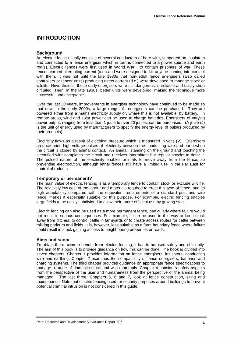
INTRODUCTION
BackgroundAn electric fence usually consists of several conductors of bare wire, supported on insulatorsand connected to a fence energiser which in turn is connected to a power source and earthrod(s). Electric fences were first used in World War I to contain prisoners of war. Thesefences carried alternating current (a.c.) and were designed to kill anyone coming into contactwith them. It was not until the late 1930s that non-lethal fence energisers (also calledcontrollers or fencer units) producing direct current (d.c.) were developed to manage stock orwildlife. Nevertheless, these early energisers were still dangerous, unreliable and easily shortcircuited. Then, in the late 1930s, better units were developed, making the technique moresuccessful and acceptable.
Over the last 30 years, improvements in energiser technology have continued to be made sothat now, in the early 2000s, a large range of energisers can be purchased. They arepowered either from a mains electricity supply or, where this is not available, by battery. Inremote areas, wind and solar power can be used to charge batteries. Energisers of varyingpower output, ranging from less than 1 joule to over 20 joules, can be purchased. (A joule (J)is the unit of energy used by manufacturers to specify the energy level of pulses produced bytheir products).
Electricity flows as a result of electrical pressure which is measured in volts (V). Energisersproduce brief, high voltage pulses of electricity between the conducting wire and earth whenthe circuit is closed by animal contact. An animal standing on the ground and touching theelectrified wire completes the circuit and receives intermittent but regular shocks to deter it.The pulsed nature of the electricity enables animals to move away from the fence, sopreventing electrocution, although lethal fences still have a limited use in the Far East forcontrol of rodents.
Temporary or permanent?The main value of electric fencing is as a temporary fence to contain stock or exclude wildlife.The relatively low cost of the labour and materials required to erect this type of fence, and itshigh adaptability compared with the equivalent requirements of a standard post and wirefence, makes it especially suitable for this purpose. For example, electric fencing enableslarge fields to be easily subdivided to allow their more efficient use by grazing stock.
Electric fencing can also be used as a more permanent fence, particularly where failure wouldnot result in serious consequences. For example, it can be used in this way to keep stockaway from ditches, to control cattle in farmyards or to create access routes for cattle betweenmilking parlours and fields. It is, however, less suitable as a farm boundary fence where failurecould result in stock gaining access to neighbouring properties or roads.
Aims and scopeTo obtain the maximum benefit from electric fencing, it has to be used safely and efficiently.The aim of this book is to provide guidance on how this can be done. The book is divided intoseven chapters. Chapter 1 provides information on fence energisers, insulators, conductingwire and earthing. Chapter 2 examines the compatibility of fence energisers, batteries andcharging systems. The third chapter provides guidance on appropriate fence specifications tomanage a range of domestic stock and wild mammals. Chapter 4 considers safety aspectsfrom the perspective of the user and humaneness from the perspective of the animal beingmanaged. The last three, Chapters 5, 6 and 7, look at fence construction, siting andmaintenance. Note that electric fencing used for security purposes around buildings to preventpotential criminal intrusion is not considered in this guide.
Electric Fence Reference Manual
Defra Research and Development Surveillance Report 607 2
CHAPTER 1
Equipment
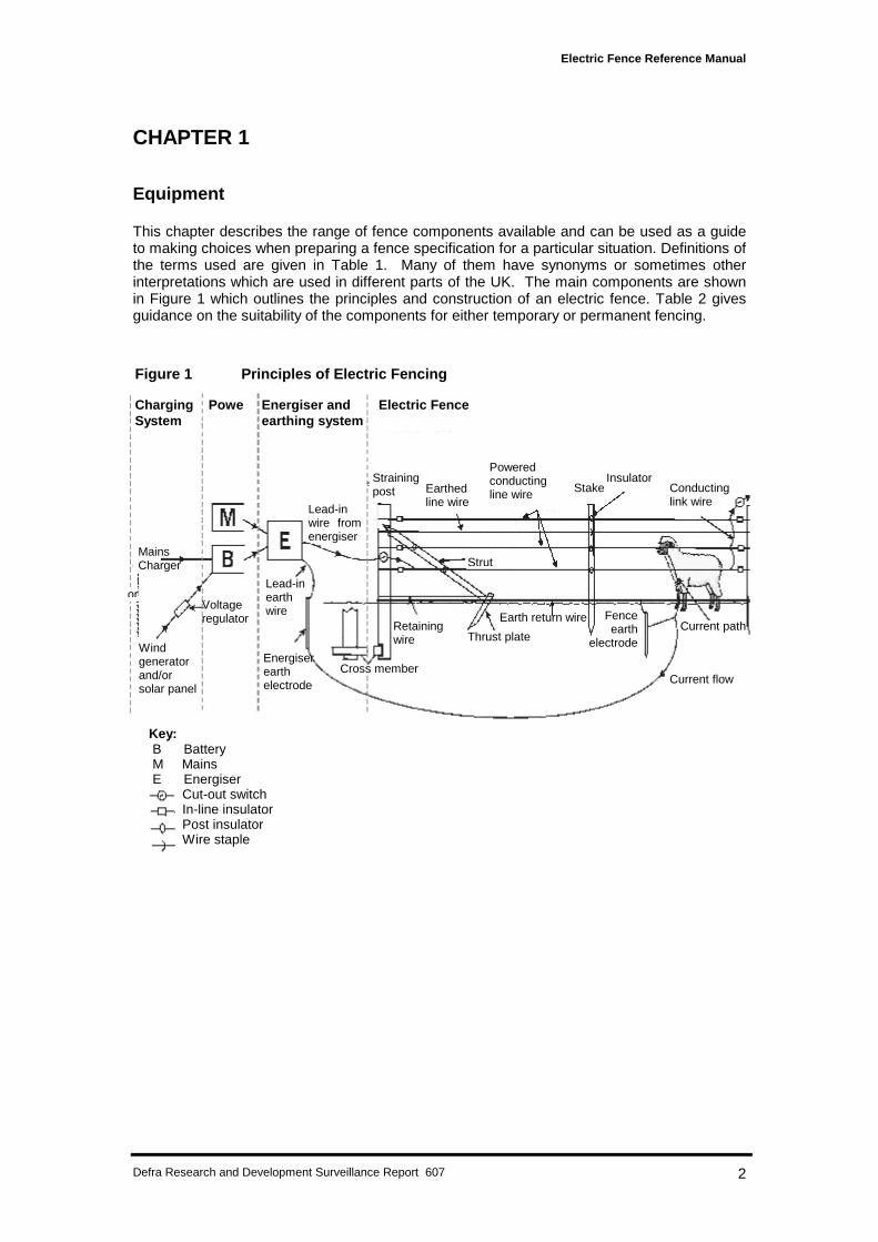
This chapter describes the range of fence components available and can be used as a guideto making choices when preparing a fence specification for a particular situation. Definitions ofthe terms used are given in Table 1. Many of them have synonyms or sometimes otherinterpretations which are used in different parts of the UK. The main components are shownin Figure 1 which outlines the principles and construction of an electric fence. Table 2 givesguidance on the suitability of the components for either temporary or permanent fencing.
ChargingSystem
Power
Figure 1 Principles of Electric Fencing
ChargingSystem
Powe Energiser andearthing system
Electric Fence
MainsCharger
or
Windgeneratorand/orsolar panel
Strainingpost Earthed
line wire
Poweredconductingline wire
InsulatorStake Conducting
link wire
Strut
Retainingwire Thrust plate
Earth return wire
Lead-inwire fromenergiser
Lead-inearthwire
Energiserearthelectrode
Voltageregulator
Current flow
Current path
Key: B Battery M Mains E Energiser Cut-out switch In-line insulator Post insulator Wire staple
Cross member
Fenceearth
electrode
Electric Fence Reference Manual
Defra Research and Development Surveillance Report 607 3
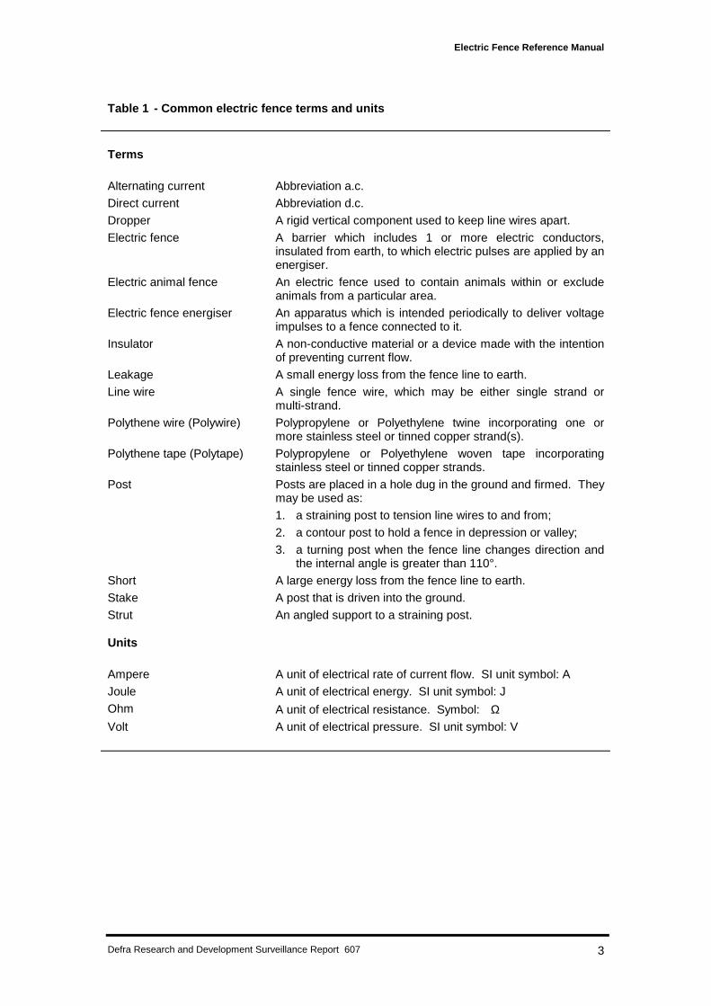
Table 1 - Common electric fence terms and units
Terms
Alternating current Abbreviation a.c.
Direct current Abbreviation d.c.
Dropper A rigid vertical component used to keep line wires apart.
Electric fence A barrier which includes 1 or more electric conductors,insulated from earth, to which electric pulses are applied by anenergiser.
Electric animal fence An electric fence used to contain animals within or excludeanimals from a particular area.
Electric fence energiser An apparatus which is intended periodically to deliver voltageimpulses to a fence connected to it.
Insulator A non-conductive material or a device made with the intentionof preventing current flow.
Leakage A small energy loss from the fence line to earth.
Line wire A single fence wire, which may be either single strand ormulti-strand.
Polythene wire (Polywire) Polypropylene or Polyethylene twine incorporating one ormore stainless steel or tinned copper strand(s).
Polythene tape (Polytape) Polypropylene or Polyethylene woven tape incorporatingstainless steel or tinned copper strands.
Post Posts are placed in a hole dug in the ground and firmed. Theymay be used as:
1. a straining post to tension line wires to and from;
2. a contour post to hold a fence in depression or valley;
3. a turning post when the fence line changes direction andthe internal angle is greater than 110°.
Short A large energy loss from the fence line to earth.
Stake A post that is driven into the ground.
Strut An angled support to a straining post.
Units
Ampere A unit of electrical rate of current flow. SI unit symbol: A
Joule A unit of electrical energy. SI unit symbol: J
Ohm A unit of electrical resistance. Symbol: ΩVolt A unit of electrical pressure. SI unit symbol: V
Electric Fence Reference Manual
Defra Research and Development Surveillance Report 607 4
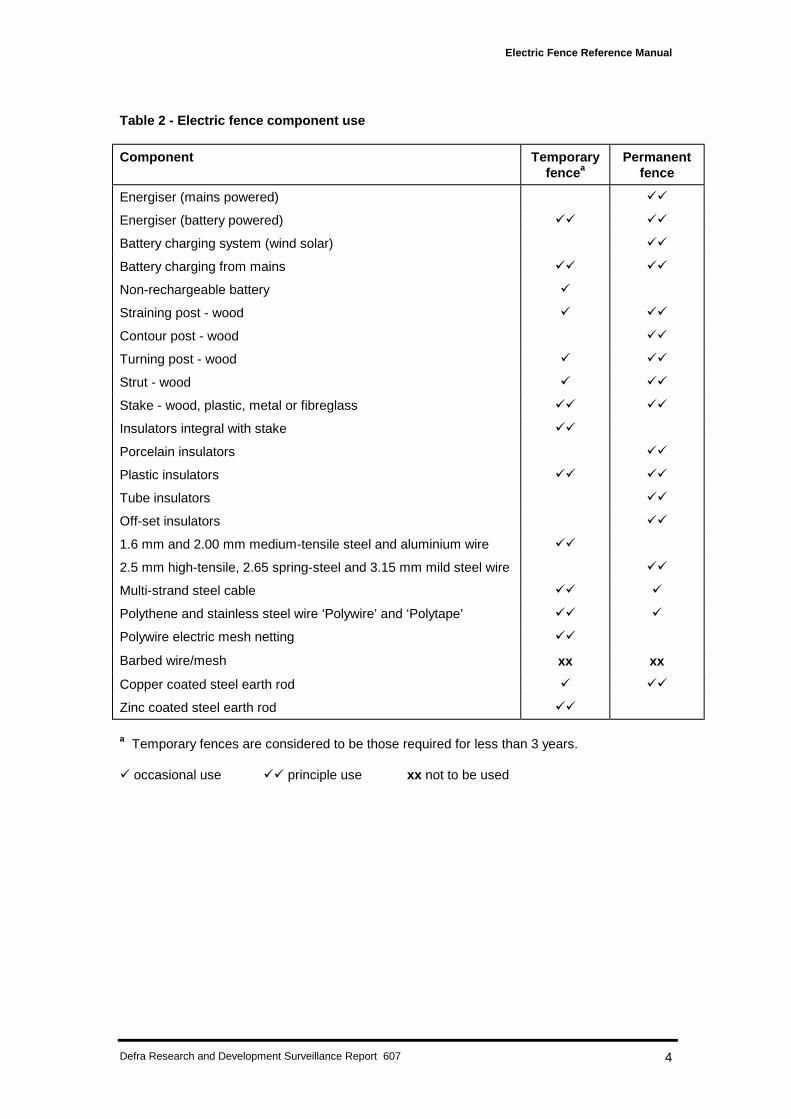
Table 2 - Electric fence component use
Component Temporaryfencea
Permanentfence
Energiser (mains powered) !!
Energiser (battery powered) !! !!
Battery charging system (wind solar) !!
Battery charging from mains !! !!
Non-rechargeable battery !
Straining post - wood ! !!
Contour post - wood !!
Turning post - wood ! !!
Strut - wood ! !!
Stake - wood, plastic, metal or fibreglass !! !!
Insulators integral with stake !!
Porcelain insulators !!
Plastic insulators !! !!
Tube insulators !!
Off-set insulators !!
1.6 mm and 2.00 mm medium-tensile steel and aluminium wire !!
2.5 mm high-tensile, 2.65 spring-steel and 3.15 mm mild steel wire !!
Multi-strand steel cable !! !
Polythene and stainless steel wire ‘Polywire’ and ‘Polytape’ !! !
Polywire electric mesh netting !!
Barbed wire/mesh xx xx
Copper coated steel earth rod ! !!
Zinc coated steel earth rod !!
a Temporary fences are considered to be those required for less than 3 years.
! occasional use !! principle use xx not to be used
Electric Fence Reference Manual
Defra Research and Development Surveillance Report 607 5
IntroductionThe objective of any electric fence must be clearly defined before any consideration is given toits detailed specification and certainly before any construction is begun. Therefore knowledgeis required about:
1. The species and sometimes breed of animal which is to be managed and its capability toscale, burrow or just force its way through a fence.
2. The pressure on the fence which is related to the number of animals on one side of thefence and their need to be on the other side.
3. The length of time an effective fence is required.4. The maximum permitted level of financial expenditure.
Electric fencing, to be effective, must have its conducting wires totally insulated and effectivelyisolated from the ground. The fence structure must be of sufficient strength and capacity todeliver an electric shock sensation to an animal when touched.
If an animal is to receive an effective shock upon contact with the bare electrified fence wire,current must be able to flow through its body to the ground. This can only happen byestablishing a very sound earthing area system which must be connected directly to theenergiser. The degree of shock sensation experienced is directly related to the level of thecurrent which can pass through the animal’s body and the time it takes to do so: the higher thecurrent and the longer it takes to pass through, the greater the shock sensation. Current levelis regulated by electrical resistance which opposes the flow of current: the higher theresistance the lower the current and the less the shock sensation experienced. A goodearthing system will help to minimise resistance, but current flow will still be affected by theresistance between those parts of the animal’s body which come in contact with the fence andwith the ground and by the resistance of the ground itself. A higher level of voltage producedby the energiser will help to overcome a high resistance path through the body, but will be oflittle consequence if the earthing system is not soundly constructed.
EnergisersThe centre of any electric fence system is the energiser. There are two types: mains operatedand battery operated. The energiser converts a.c. or d.c. voltage, respectively, into repetitivehigh voltage pulses of d.c. voltage which are delivered along the entire length of a fenceconnected to it. Each pulse lasts for a very short time (approximately 500 microseconds) andis produced at one second intervals. Thus, fence energisers are constantly switching on andoff, and it is this characteristic which is responsible for preventing a fatality under normaloperating conditions. The voltage peak of each consecutive pulse can rise to a limit of 10,000V; values exceeding this limit are considered unsafe by present international safetystandards.
Voltage is not the only aspect to be taken into consideration where safety is concerned. Eachpulse will contain a potential quantity of electrical energy. This quantity of electrical energy ismeasured in joules (J). Energisers with an output in excess of 5 J are not recommendedunder UK Health and Safety codes of practice, although those producing up to 20 J arenevertheless available on the market.
Each of the mains operated and battery operated energisers are sub-divided into the twocategories of high or low power. Many of the energisers available allow the choice of eitherlow or high energy outputs. These outputs are usually available from colour coded terminalson the energiser. A red coloured terminal will usually identify the higher output and a yellowcoloured terminal the lower output. The earth terminal, common to either output, is green.The most recent designs of energisers have digital liquid crystal display providing certaincharacteristics of the output on the fence, such as fence voltage and earth leakage.
There are three important factors to be considered when choosing an energiser:• fence location• animals to be controlled
Electric Fence Reference Manual
Defra Research and Development Surveillance Report 607 6
• fence length.
Under most circumstances, fence location will dictate the selection between a mains or batterypowered energiser. For example, in remote areas where no mains supply is available, the onlyoption will be a battery powered unit. When a battery powered energiser is selected,consideration must be given to replacing or recharging the battery which, with a higherpowered energiser, may be as frequently as every two weeks. Thus, where there is a choice,mains operated energisers are preferable to avoid the problems of battery charging andmaintenance.
Different species of animals vary in their susceptibility to electric fence shocks. Some, suchas pigs, are relatively easy to control: as little as 300 millijoules (mJ) of energy on a well-insulated fence with a sound earthing system will deter them. Animals with fur generallyrequire more energy capacity on the fence to receive an effective shock. Body size is alsoimportant. Generally the larger the animal the greater the energy capacity needed. Forexample, rabbits and foxes require less energy (they need about 1.5 J) than sheep and deer.Deer generally represent one of the most difficult animals to control by electric fencing andhigh powered energisers are essential.
The fence manufacturer will usually specify the maximum length of fence that their energiserwill power effectively. The length of fence, for multi-strand fences, is the total length ofconductor wire used. Thus, an energiser capable of powering a 4 km (2.5 miles) length offence can be used on either a 2 km (about 1.2 miles) fence of 2-line wires or 1 km (about 0.6miles) fence of 4-line wires.
BatteriesSome low power energisers can be used with dry cell batteries which are designed to be usedand discarded. However, most energisers require rechargeable lead acid batteries. Therequired voltage of the battery will be specified by the energiser manufacturer and the capacityof the battery can be determined from the proposed usage and method of charging. Batteriesthat are not designed for cyclic discharge and recharge (car starter batteries, for example) willdeteriorate rapidly if not maintained at or near full charge. Leisure batteries (for example,those used in caravans) are more appropriate.
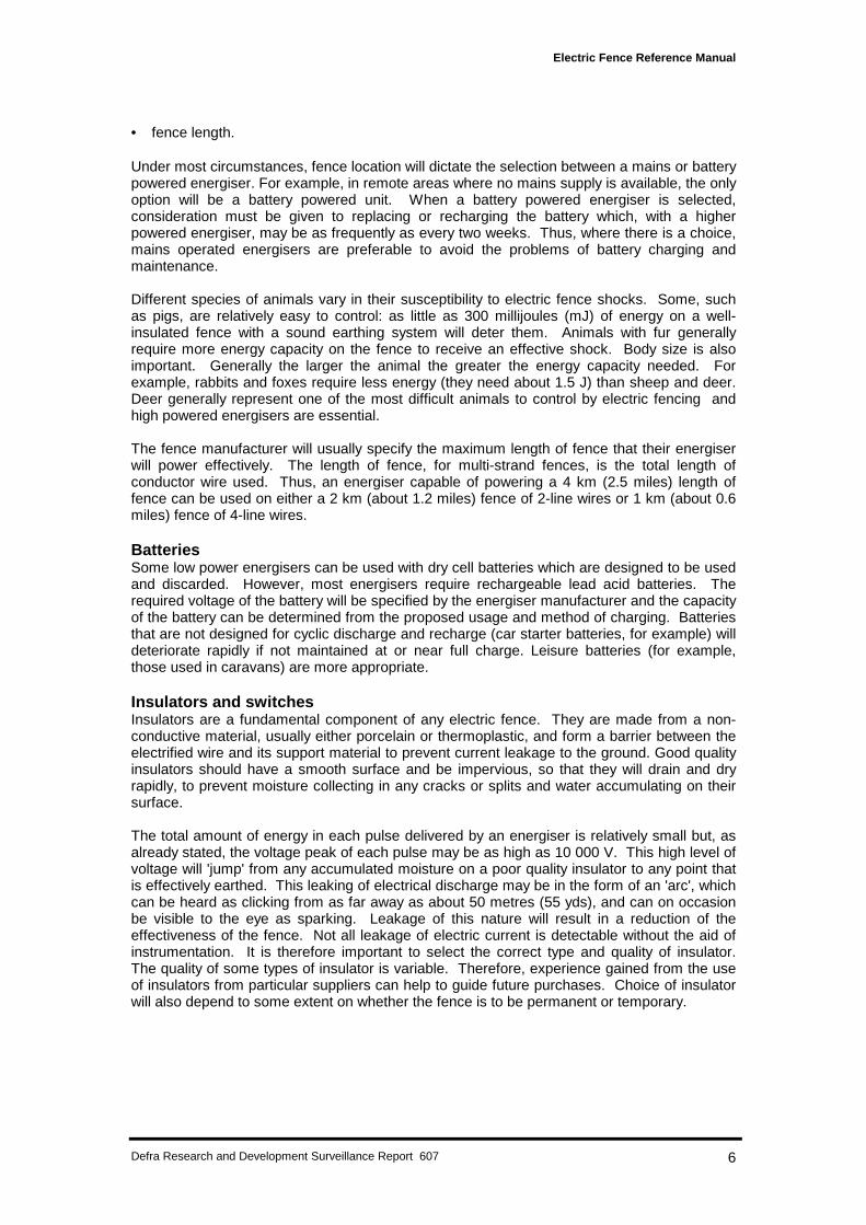
Insulators and switchesInsulators are a fundamental component of any electric fence. They are made from a non-conductive material, usually either porcelain or thermoplastic, and form a barrier between theelectrified wire and its support material to prevent current leakage to the ground. Good qualityinsulators should have a smooth surface and be impervious, so that they will drain and dryrapidly, to prevent moisture collecting in any cracks or splits and water accumulating on theirsurface.
The total amount of energy in each pulse delivered by an energiser is relatively small but, asalready stated, the voltage peak of each pulse may be as high as 10 000 V. This high level ofvoltage will 'jump' from any accumulated moisture on a poor quality insulator to any point thatis effectively earthed. This leaking of electrical discharge may be in the form of an 'arc', whichcan be heard as clicking from as far away as about 50 metres (55 yds), and can on occasionbe visible to the eye as sparking. Leakage of this nature will result in a reduction of theeffectiveness of the fence. Not all leakage of electric current is detectable without the aid ofinstrumentation. It is therefore important to select the correct type and quality of insulator.The quality of some types of insulator is variable. Therefore, experience gained from the useof insulators from particular suppliers can help to guide future purchases. Choice of insulatorwill also depend to some extent on whether the fence is to be permanent or temporary.

Electric Fence Reference Manual
Defra Research and Development Surveillance Report 607 7
Figure 2 Insulating conductor wires from straining posts
Porcelain insulatorsPorcelain insulators (Plate 1) have the best insulation properties and, if of good quality, are thestrongest. They are therefore particularly suitable to insulate tensioned line wires fromstraining and turning posts (Figure 2). They are fire resistant and can prevent any electricalarcing causing a fire. Their main disadvantage is their relatively high cost and, as a result,they are mainly used on permanent fencing. Poor quality porcelain insulators may be fragileunder tension; they may also crack allowing absorption and retention of moisture giving rise toconductive deposits.
Plastic insulatorsMoulded from either polythene or polypropylene, plastic insulators are the most common typein use today. They are cheap and because they can be moulded into any suitable shape(Plate 1) they are easy to fit. The more basic and smoother designs are better as they havefewer ledges, cavities or holes to gather moisture. The most durable plastic insulators arefully ultra-violet (UV) light inhibited, normally with carbon black, to prevent degradation insunlight.
Plastic tube insulatorsThese insulators are designed to enclose the electrified wire to allow it to be held against andstapled to a post (Plate 1). Plastic tube insulators are particularly useful for taking a line wirearound a turning post or terminating it at a straining or gate post, particularly when the wire ismade of high-tensile or spring-steel (Figure 2). Some have a reinforcing metal strip inside thetube to prevent the tensioned wire splitting the plastic. Various types of plastic tube includinggarden hose pipe are utilised on a 'make do' basis. However, it is recommended that onlyplastic tube manufactured and supplied specifically for electric fencing is stipulated for use.Even these can collect conducting agents (e.g. dead insects and acid rain) which may reducetheir insulation properties.
Poweredconductingline wire
In-line insulator(plastic or porcelain)
Plastic tubeinsulator
Poweredconductingline wire
Reinforcingmetal strip
Electric Fence Reference Manual
Defra Research and Development Surveillance Report 607 8
Plate 1 - Examples of the range of insulators currently available
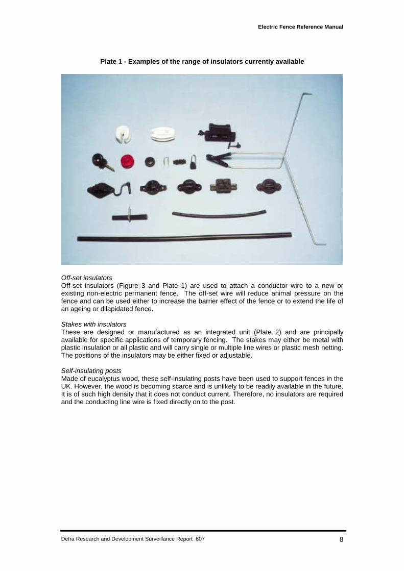
Off-set insulatorsOff-set insulators (Figure 3 and Plate 1) are used to attach a conductor wire to a new orexisting non-electric permanent fence. The off-set wire will reduce animal pressure on thefence and can be used either to increase the barrier effect of the fence or to extend the life ofan ageing or dilapidated fence.
Stakes with insulatorsThese are designed or manufactured as an integrated unit (Plate 2) and are principallyavailable for specific applications of temporary fencing. The stakes may either be metal withplastic insulation or all plastic and will carry single or multiple line wires or plastic mesh netting.The positions of the insulators may be either fixed or adjustable.
Self-insulating postsMade of eucalyptus wood, these self-insulating posts have been used to support fences in theUK. However, the wood is becoming scarce and is unlikely to be readily available in the future.It is of such high density that it does not conduct current. Therefore, no insulators are requiredand the conducting line wire is fixed directly on to the post.
Electric Fence Reference Manual
Defra Research and Development Surveillance Report 607 9
Figure 3 Off-set insulators in position
Plate 2 - Metal fence stake with adjustable insulators
Plastic Insulationsleeve
Powered conductingline wire
Moulded plasticinsulator
Non-electric permanentfence wires
Electric Fence Reference Manual
Defra Research and Development Surveillance Report 607 10
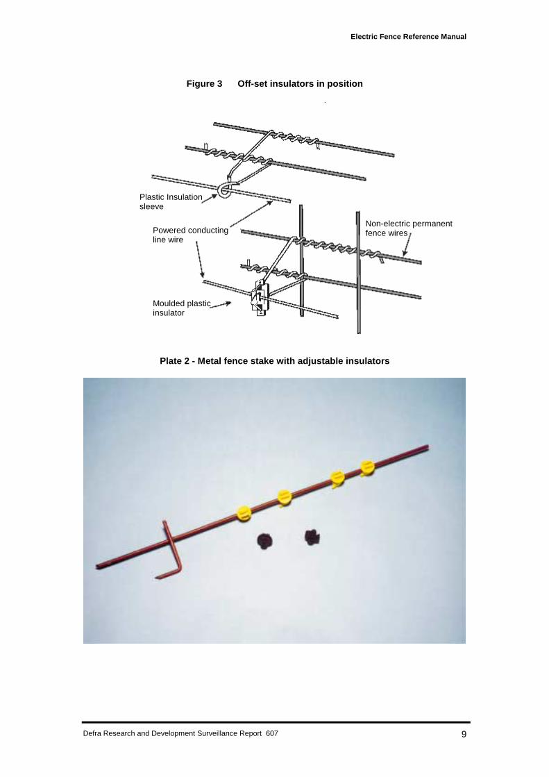
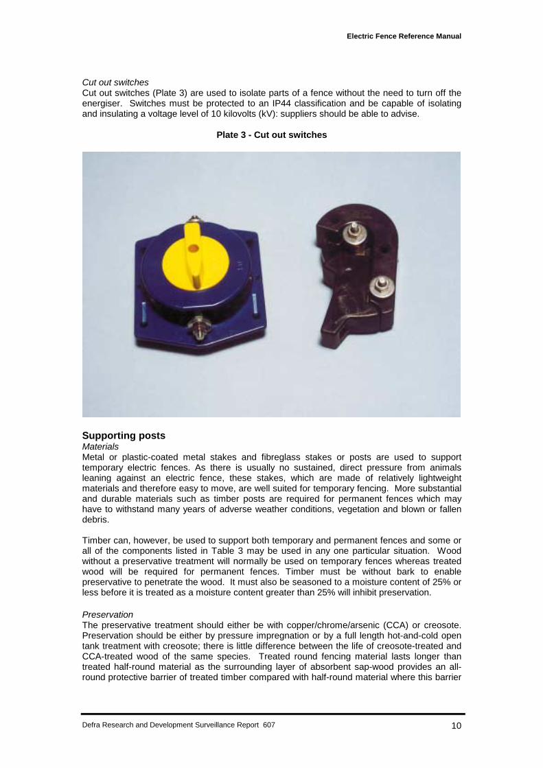
Cut out switchesCut out switches (Plate 3) are used to isolate parts of a fence without the need to turn off theenergiser. Switches must be protected to an IP44 classification and be capable of isolatingand insulating a voltage level of 10 kilovolts (kV): suppliers should be able to advise.
Plate 3 - Cut out switches
Supporting postsMaterialsMetal or plastic-coated metal stakes and fibreglass stakes or posts are used to supporttemporary electric fences. As there is usually no sustained, direct pressure from animalsleaning against an electric fence, these stakes, which are made of relatively lightweightmaterials and therefore easy to move, are well suited for temporary fencing. More substantialand durable materials such as timber posts are required for permanent fences which mayhave to withstand many years of adverse weather conditions, vegetation and blown or fallendebris.
Timber can, however, be used to support both temporary and permanent fences and some orall of the components listed in Table 3 may be used in any one particular situation. Woodwithout a preservative treatment will normally be used on temporary fences whereas treatedwood will be required for permanent fences. Timber must be without bark to enablepreservative to penetrate the wood. It must also be seasoned to a moisture content of 25% orless before it is treated as a moisture content greater than 25% will inhibit preservation.
PreservationThe preservative treatment should either be with copper/chrome/arsenic (CCA) or creosote.Preservation should be either by pressure impregnation or by a full length hot-and-cold opentank treatment with creosote; there is little difference between the life of creosote-treated andCCA-treated wood of the same species. Treated round fencing material lasts longer thantreated half-round material as the surrounding layer of absorbent sap-wood provides an all-round protective barrier of treated timber compared with half-round material where this barrier
Electric Fence Reference Manual
Defra Research and Development Surveillance Report 607 11
is absent over half of the timber. In general, preservative treated hardwoods do not last aslong as similarly treated softwoods.
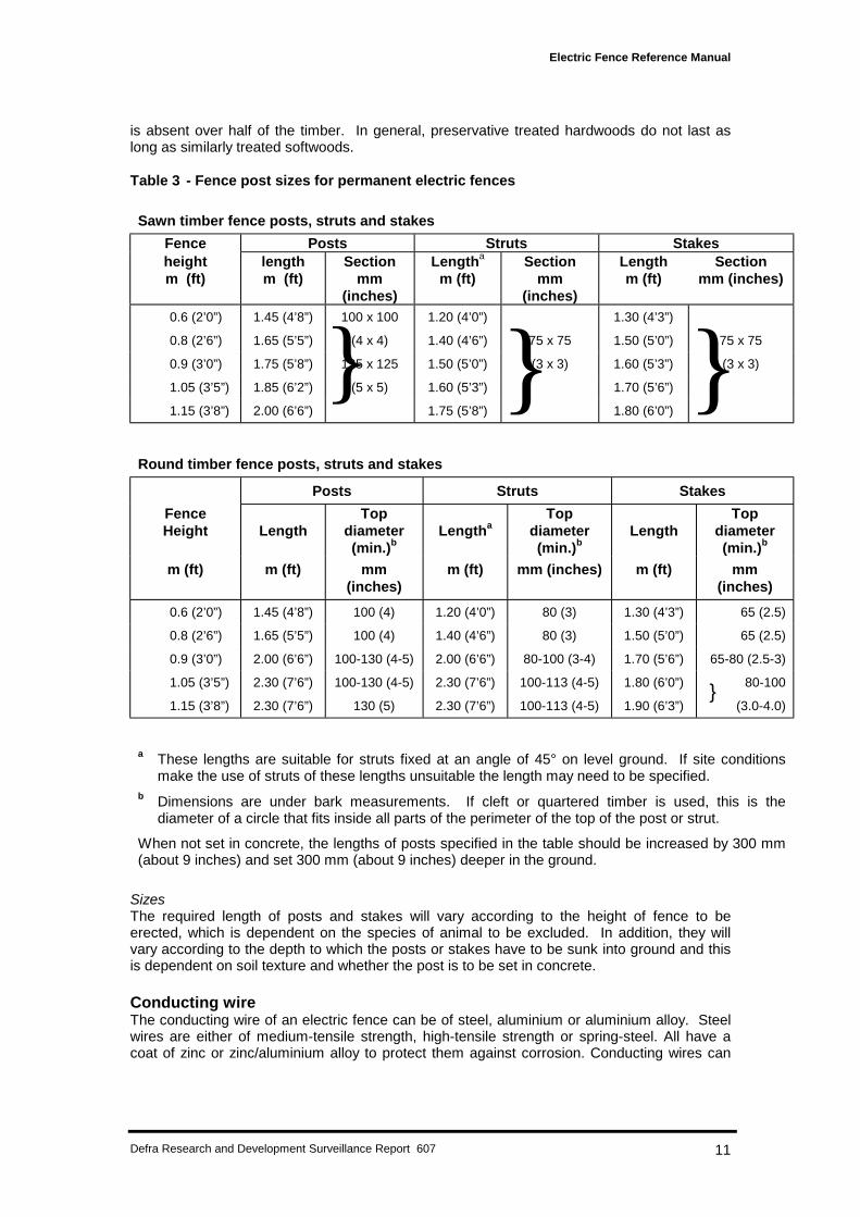
Table 3 - Fence post sizes for permanent electric fences
Sawn timber fence posts, struts and stakes
Fence Posts Struts Stakesheight length Section Lengtha Section Length Sectionm (ft) m (ft) mm
(inches)m (ft) mm
(inches)m (ft) mm (inches)
0.6 (2’0”) 1.45 (4’8”) 100 x 100 1.20 (4’0”) 1.30 (4’3”)
0.8 (2’6”) 1.65 (5’5”) (4 x 4) 1.40 (4’6”) 75 x 75 1.50 (5’0”) 75 x 75
0.9 (3’0”) 1.75 (5’8”) 125 x 125 1.50 (5’0”) (3 x 3) 1.60 (5’3”) (3 x 3)
1.05 (3’5”) 1.85 (6’2”) (5 x 5) 1.60 (5’3”) 1.70 (5’6”)
1.15 (3’8”) 2.00 (6’6”) 1.75 (5’8”) 1.80 (6’0”)
Round timber fence posts, struts and stakes
Posts Struts Stakes
FenceHeight Length
Topdiameter(min.)b
LengthaTop
diameter(min.)b
LengthTop
diameter(min.)b
m (ft) m (ft) mm(inches)
m (ft) mm (inches) m (ft) mm(inches)
0.6 (2’0”) 1.45 (4’8”) 100 (4) 1.20 (4’0”) 80 (3) 1.30 (4’3”) 65 (2.5)
0.8 (2’6”) 1.65 (5’5”) 100 (4) 1.40 (4’6”) 80 (3) 1.50 (5’0”) 65 (2.5)
0.9 (3’0”) 2.00 (6’6”) 100-130 (4-5) 2.00 (6’6”) 80-100 (3-4) 1.70 (5’6”) 65-80 (2.5-3)
1.05 (3’5”) 2.30 (7’6”) 100-130 (4-5) 2.30 (7’6”) 100-113 (4-5) 1.80 (6’0”) 80-100
1.15 (3’8”) 2.30 (7’6”) 130 (5) 2.30 (7’6”) 100-113 (4-5) 1.90 (6’3”) (3.0-4.0)
a These lengths are suitable for struts fixed at an angle of 45° on level ground. If site conditionsmake the use of struts of these lengths unsuitable the length may need to be specified.
b Dimensions are under bark measurements. If cleft or quartered timber is used, this is thediameter of a circle that fits inside all parts of the perimeter of the top of the post or strut.
When not set in concrete, the lengths of posts specified in the table should be increased by 300 mm(about 9 inches) and set 300 mm (about 9 inches) deeper in the ground.
SizesThe required length of posts and stakes will vary according to the height of fence to beerected, which is dependent on the species of animal to be excluded. In addition, they willvary according to the depth to which the posts or stakes have to be sunk into ground and thisis dependent on soil texture and whether the post is to be set in concrete.
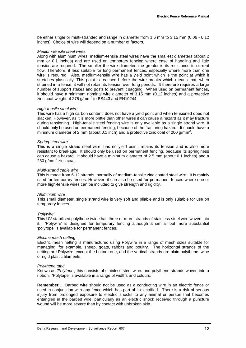
Conducting wireThe conducting wire of an electric fence can be of steel, aluminium or aluminium alloy. Steelwires are either of medium-tensile strength, high-tensile strength or spring-steel. All have acoat of zinc or zinc/aluminium alloy to protect them against corrosion. Conducting wires can
Electric Fence Reference Manual
Defra Research and Development Surveillance Report 607 12
be either single or multi-stranded and range in diameter from 1.6 mm to 3.15 mm (0.06 - 0.12inches). Choice of wire will depend on a number of factors.
Medium-tensile steel wiresAlong with aluminium wires, medium-tensile steel wires have the smallest diameters (about 2mm or 0.1 inches) and are used on temporary fencing where ease of handling and littletension are required. The smaller the wire diameter, the greater is its resistance to currentflow. Therefore, it less suitable for long permanent fences, especially where more than onewire is required. Also, medium-tensile wire has a yield point which is the point at which itstretches plastically. This point is reached before the wire breaks which means that, whenstrained in a fence, it will not retain its tension over long periods. It therefore requires a largenumber of support stakes and posts to prevent it sagging. When used on permanent fences,it should have a minimum nominal wire diameter of 3.15 mm (0.12 inches) and a protectivezinc coat weight of 275 g/mm2 to BS443 and EN10244.
High-tensile steel wireThis wire has a high carbon content, does not have a yield point and when tensioned does notslacken. However, as it is more brittle than other wires it can cause a hazard as it may fractureduring tensioning. High-tensile steel fencing wire is only available as a single strand wire. Itshould only be used on permanent fencing, because of the fracturing hazard. It should have aminimum diameter of 2 mm (about 0.1 inch) and a protective zinc coat of 200 g/mm2.
Spring-steel wireThis is a single strand steel wire, has no yield point, retains its tension and is also moreresistant to breakage. It should only be used on permanent fencing, because its springinesscan cause a hazard. It should have a minimum diameter of 2.5 mm (about 0.1 inches) and a230 g/mm2 zinc coat.
Multi-strand cable wireThis is made from 6-12 strands, normally of medium-tensile zinc coated steel wire. It is mainlyused for temporary fences. However, it can also be used for permanent fences where one ormore high-tensile wires can be included to give strength and rigidity.
Aluminium wireThis small diameter, single strand wire is very soft and pliable and is only suitable for use ontemporary fences.
'Polywire'This UV stabilised polythene twine has three or more strands of stainless steel wire woven intoit. 'Polywire' is designed for temporary fencing although a similar but more substantial'polyrope' is available for permanent fences.
Electric mesh nettingElectric mesh netting is manufactured using Polywire in a range of mesh sizes suitable formanaging, for example, sheep, goats, rabbits and poultry. The horizontal strands of thenetting are Polywire, except the bottom one, and the vertical strands are plain polythene twineor rigid plastic filaments.
Polythene tapeKnown as 'Polytape', this consists of stainless steel wires and polythene strands woven into aribbon. 'Polytape' is available in a range of widths and colours.
Remember ... Barbed wire should not be used as a conducting wire in an electric fence orused in conjunction with any fence which has part of it electrified. There is a risk of seriousinjury from prolonged exposure to electric shocks to any animal or person that becomesentangled in the barbed wire, particularly as an electric shock received through a puncturewound will be more severe than by contact with unbroken skin.
Electric Fence Reference Manual
Defra Research and Development Surveillance Report 607 13
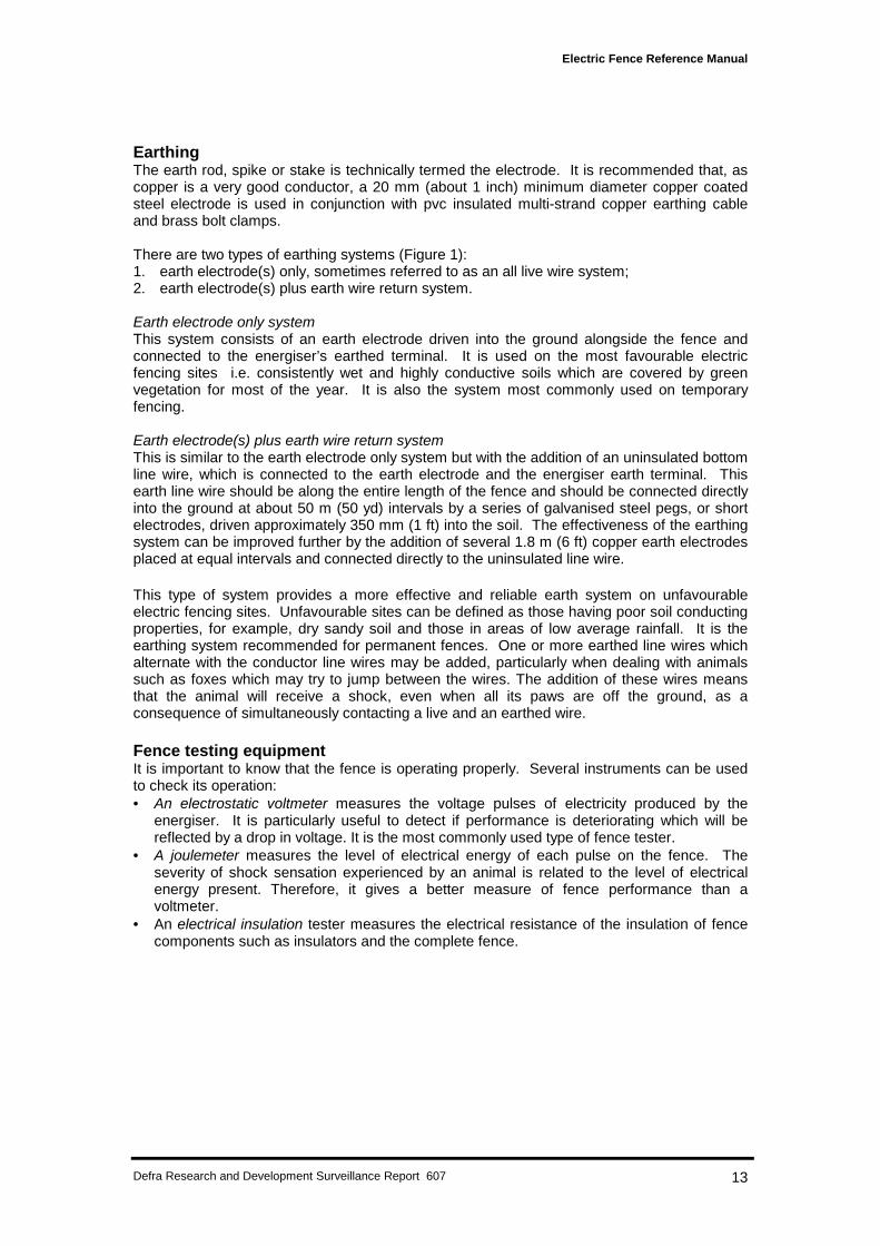
EarthingThe earth rod, spike or stake is technically termed the electrode. It is recommended that, ascopper is a very good conductor, a 20 mm (about 1 inch) minimum diameter copper coatedsteel electrode is used in conjunction with pvc insulated multi-strand copper earthing cableand brass bolt clamps.
There are two types of earthing systems (Figure 1):1. earth electrode(s) only, sometimes referred to as an all live wire system;2. earth electrode(s) plus earth wire return system.
Earth electrode only systemThis system consists of an earth electrode driven into the ground alongside the fence andconnected to the energiser’s earthed terminal. It is used on the most favourable electricfencing sites i.e. consistently wet and highly conductive soils which are covered by greenvegetation for most of the year. It is also the system most commonly used on temporaryfencing.
Earth electrode(s) plus earth wire return systemThis is similar to the earth electrode only system but with the addition of an uninsulated bottomline wire, which is connected to the earth electrode and the energiser earth terminal. Thisearth line wire should be along the entire length of the fence and should be connected directlyinto the ground at about 50 m (50 yd) intervals by a series of galvanised steel pegs, or shortelectrodes, driven approximately 350 mm (1 ft) into the soil. The effectiveness of the earthingsystem can be improved further by the addition of several 1.8 m (6 ft) copper earth electrodesplaced at equal intervals and connected directly to the uninsulated line wire.
This type of system provides a more effective and reliable earth system on unfavourableelectric fencing sites. Unfavourable sites can be defined as those having poor soil conductingproperties, for example, dry sandy soil and those in areas of low average rainfall. It is theearthing system recommended for permanent fences. One or more earthed line wires whichalternate with the conductor line wires may be added, particularly when dealing with animalssuch as foxes which may try to jump between the wires. The addition of these wires meansthat the animal will receive a shock, even when all its paws are off the ground, as aconsequence of simultaneously contacting a live and an earthed wire.
Fence testing equipmentIt is important to know that the fence is operating properly. Several instruments can be usedto check its operation:• An electrostatic voltmeter measures the voltage pulses of electricity produced by the
energiser. It is particularly useful to detect if performance is deteriorating which will bereflected by a drop in voltage. It is the most commonly used type of fence tester.
• A joulemeter measures the level of electrical energy of each pulse on the fence. Theseverity of shock sensation experienced by an animal is related to the level of electricalenergy present. Therefore, it gives a better measure of fence performance than avoltmeter.
• An electrical insulation tester measures the electrical resistance of the insulation of fencecomponents such as insulators and the complete fence.
Electric Fence Reference Manual
Defra Research and Development Surveillance Report 607 14
CHAPTER 2
Compatibility of components used with battery operated energisers
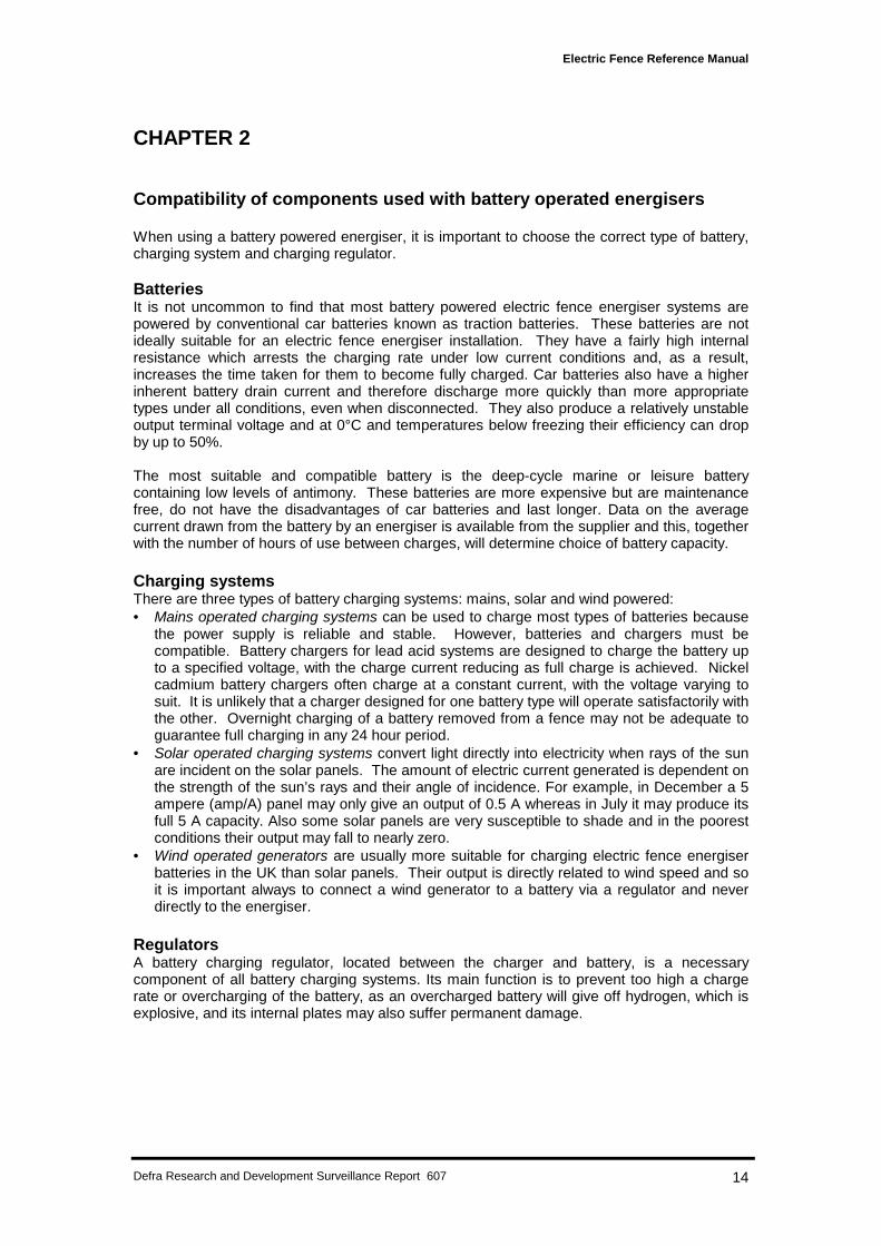
When using a battery powered energiser, it is important to choose the correct type of battery,charging system and charging regulator.
BatteriesIt is not uncommon to find that most battery powered electric fence energiser systems arepowered by conventional car batteries known as traction batteries. These batteries are notideally suitable for an electric fence energiser installation. They have a fairly high internalresistance which arrests the charging rate under low current conditions and, as a result,increases the time taken for them to become fully charged. Car batteries also have a higherinherent battery drain current and therefore discharge more quickly than more appropriatetypes under all conditions, even when disconnected. They also produce a relatively unstableoutput terminal voltage and at 0°C and temperatures below freezing their efficiency can dropby up to 50%.
The most suitable and compatible battery is the deep-cycle marine or leisure batterycontaining low levels of antimony. These batteries are more expensive but are maintenancefree, do not have the disadvantages of car batteries and last longer. Data on the averagecurrent drawn from the battery by an energiser is available from the supplier and this, togetherwith the number of hours of use between charges, will determine choice of battery capacity.
Charging systemsThere are three types of battery charging systems: mains, solar and wind powered:• Mains operated charging systems can be used to charge most types of batteries because
the power supply is reliable and stable. However, batteries and chargers must becompatible. Battery chargers for lead acid systems are designed to charge the battery upto a specified voltage, with the charge current reducing as full charge is achieved. Nickelcadmium battery chargers often charge at a constant current, with the voltage varying tosuit. It is unlikely that a charger designed for one battery type will operate satisfactorily withthe other. Overnight charging of a battery removed from a fence may not be adequate toguarantee full charging in any 24 hour period.
• Solar operated charging systems convert light directly into electricity when rays of the sunare incident on the solar panels. The amount of electric current generated is dependent onthe strength of the sun’s rays and their angle of incidence. For example, in December a 5ampere (amp/A) panel may only give an output of 0.5 A whereas in July it may produce itsfull 5 A capacity. Also some solar panels are very susceptible to shade and in the poorestconditions their output may fall to nearly zero.
• Wind operated generators are usually more suitable for charging electric fence energiserbatteries in the UK than solar panels. Their output is directly related to wind speed and soit is important always to connect a wind generator to a battery via a regulator and neverdirectly to the energiser.
RegulatorsA battery charging regulator, located between the charger and battery, is a necessarycomponent of all battery charging systems. Its main function is to prevent too high a chargerate or overcharging of the battery, as an overcharged battery will give off hydrogen, which isexplosive, and its internal plates may also suffer permanent damage.
Electric Fence Reference Manual
Defra Research and Development Surveillance Report 607 15
Some of the more expensive charging regulators use integral switching relays which inthemselves can use more current than is fed into them. Under these conditions, the regulatorwill further drain the battery. These regulators are therefore suitable only for use with mainschargers and high output wind generators. Cheaper and more simple regulators withoutswitching relays are therefore more suitable for use with most wind generators and solarpanels.
Careful consideration should be given to the siting of a regulator since it may become hot asany excess energy is dissipated. Therefore it should be mounted where it will not be a firehazard.
Electric Fence Reference Manual
Defra Research and Development Surveillance Report 607 16
CHAPTER 3
Fence specifications
IntroductionElectric fences are cheaper to construct than conventional fences because they do not have tobe robust impenetrable barriers which require considerably more time and materials to erect.Electric fences instead operate by modifying animal behaviour: animals are repelled by theshock sensation received from fences and learn to avoid them. Thus, for a fence design to besuccessful, it must take account of animal behaviour. Until recently most designs appear tohave been developed largely by trial and error, particularly those deployed to try to managewild mammals, as the main aim was to use as little fencing material as possible to keep costslow. The specifications given in this chapter, particularly for fences to manage wild mammals,have been obtained from scientific reports where animal behaviour has been of crucialimportance in designing the fence.
Encountering the fence for the first timeAn electric fence encountered for the first time by a wild mammal is an unfamiliar object whichthe animal will investigate, usually by touch, using its nose. Domestic stock familiar withelectric fencing are also likely to investigate new fences by touch with their nose. By contrast,stock unfamiliar with electric fencing are more likely to try to push through the large spacesbetween wires, thereby touching the wires with their neck, back or chest. Wild animals mayalso make this type of contact if they do not see the fence before touching it, which can oftenbe the case with nocturnal species.
The intensity of the shock felt by an animal determines its subsequent reaction to the fence.Different species, as well as individual animals within a species, may react differently. Ananimal which touches a wire with its nose, which is poorly insulated and highly innervated,usually receives a severe shock which is likely to deter it from crossing the fence. By contrast,an animal which touches a wire with a less sensitive area, such as its neck, back or chest,may not even receive a shock and may cross the fence. Furthermore, if an animal is movingswiftly and has almost crossed before the electrical pulse is generated, it is likely to completethe crossing. Similarly, if an animal jumps through and is off the ground when it contacts livewires it will not receive a shock. A danger is that any animal that passes through or over afence will be retained within the fenced area.
Principles of effective fence designIn designing an effective fence the factors discussed above need to be taken intoconsideration.
Number and positioning of wiresThe number of wires in the fence and their positioning also depend on the size and agility ofthe species being managed. For example, fences designed to exclude smaller, agile species,such as wild rabbits, require more wires than fences designed to contain larger, less agileanimals such as cattle. The number and positioning of wires should be sufficient to stopanimals being easily able to push through the wires or jump over them. Jumping over,however, has not been recorded as a method of crossing as often as might be expected,considering that the heights of the fences are generally less than the species concerned canjump. For example, a height of 45 cm (1.5 ft.) has been used successfully to exclude foxesand a height of 50 cm (about 1.5 ft) to exclude rabbits. Therefore, it would appear thatreceiving a shock deters animals from attempting to jump fences. All species of deer in theUK, however, provide an exception as they have regularly been recorded jumping over fencesup to 1.1 m (about 4 ft.) high.
Electric Fence Reference Manual
Defra Research and Development Surveillance Report 607 17
Alternating live and earthed wiresEarthed wires can also be added to the system so that they alternate with live wires in such away that animals pushing through the fence touch both live and earthed wires simultaneously.This earthing design is likely to result in a more severe shock being received by the animalthan that received when the animal is earthed solely through its paws or hoofs. However, thecloser the wires, the less the shock sensation that will be felt, as it is proportional to thedistance the current travels through the animal’s body.
For animals trying to jump through fences, the use of alternating live and earthed wires canalso ensure that the animal will actually receive a shock which would not be the case if it wasoff the ground when it contacted an all live wire fence. The main drawback to the use ofearthed wires is that it increases the likelihood of a dead short if live and earthed wires were tocome into contact. Therefore, adding extra live wires should always be considered first.
For smaller animals, such as rabbits, which may try to crawl under the lowest electrified wire,insertion of an earthed wire close to the ground is often the only feasible way to prevent themcrossing in this way. Inserting an additional electrified wire so close to the ground is usuallyimpracticable as inevitably it would result in the fence being short circuited by touching theground or vegetation. The earthed wire is positioned close to the ground so that the animalmust pass over it, forcing it up and into contact with the lowest electrified wire.
Surprisingly, digging under electric fences is not a serious problem. Rabbits and badgers, forexample, both dig under wire netting fences and could be expected to burrow under electricfences but this has rarely been recorded. Therefore, it appears that receiving shocks detersthese animals from spending the time required near to the fence to dig under it.
Planning the fence perimeterFences will normally encircle an area either to contain animals or exclude them. The electricfence may form the complete circle or it may just be part of the circle and be in combinationwith a standard post and wire or mesh fence. On the occasions when the fence is notrequired to encircle an area, wild animals have been recorded going round the ends of thefence. For example, foxes went around a fence erected across a peninsula to protectsandwich terns, and rabbits have gone around fences extended 50 m (about 50 yds) past theirburrows. One solution, which is particularly applicable where animals have relatively smallhome ranges in relation to the area being protected, is to extend the fence so that the endsare located outside the home ranges of the individuals being excluded. For example, rabbitsrarely move more than 150 m (about 170 yds) from their burrows and so any fence extendedto this distance from their harbourage is likely to be effective. Another solution is to cull theindividuals which are circumventing. This was done in the case of the specific foxes whichwere going round the ends of the fences protecting the sandwich tern colony and has beenused to prevent 'rogue' stock animals crossing fences.
Animal training and managementAnimal behaviour can be modified to ensure fences are effective. Domestic stock can betaught that an electric fence is different from a conventional fence. This can be done byputting the stock inside a small enclosure, usually of <1 ha (about 2.5 acres), formed by astout conventional wire fence to which an electrified wire is attached on the inside as an out-rigger. Animals are kept in this training yard at high stocking rates to maximise the likelihoodof contacts with the electrified wire, but are prevented from pushing past it by the conventionalfence. Trained animals have subsequently been shown to touch electric fences enclosingfields less often than untrained animals. Another training method is to tether the animals closeto the fence so that they can touch but not cross it.
Stock can be encouraged to investigate an electric fence by attaching unfamiliar and highlyvisible objects to it. This method also makes a fence more conspicuous and, therefore,animals which otherwise may have run through the fence can be encouraged to investigate it.Strips of plastic, luminous hazard warning tape and plastic bottles have been used for this
Electric Fence Reference Manual
Defra Research and Development Surveillance Report 607 18
purpose. Food items, such as kale or hay, have also been used in this way which makesthe fence not only unfamiliar, but also attractive. However, this general approach has thedisadvantage that animals may associate the shock received only with fences to which objectsare attached.
Another possibility for stock management is to erect parallel electrified wires, so that thevegetation growing between them forms a more conspicuous, attractive barrier. Thiscombination is usually referred to as a 'grassfence'. However, it has disadvantages in that ituses grazing land, is slow to establish, and can encourage the spread of weeds from thegrass strip.
Additional techniquesThe severity of the shock can also be increased by sheering domestic stock, such as sheep orgoats, immediately before they are first released into a field enclosed by electric fencing.
Electric fences can also be designed, using material other than wire to carry the current, tomake the fence look unfamiliar and therefore encourage investigation. For example, polytapetwists and moves in the wind when loosely tensioned between posts. These tapes have beensuccessfully used to contain horses but are relatively expensive and not very durable.
Remember ... the use of electrified barbed wire, which would increase the severity of anelectric shock by penetrating animals’ insensitive hide or fur, is illegal in Great Britain as thereis a danger that animals or people could become caught on the barbs, receive shocksrepeatedly and possibly be killed.
In conclusion, the best solutions to prevent fence crossing are:• for domestic stock, training them to investigate the fence• for wild animals, the addition of extra wires either live or, where necessary, earthed.
Specifications for domestic stockElectric fencing has been successfully used to manage most types of livestock and usuallyone or two line wires is sufficient. Polywire is usually an adequate alternative to steel as theconductor. In addition, a range of commercially available polywire electric netting fences areavailable to manage most stock. Details of suppliers are given in Appendix 1. Irrespectiveof the type of conducting wire used, good straining is important to avoid variation in the heightof the wire due to sagging and to ensure good contact when the animal pushes against it. Onuneven ground, additional supporting posts will be needed to ensure that the wire is at areasonably uniform height. The specification for each species is given in Table 4.
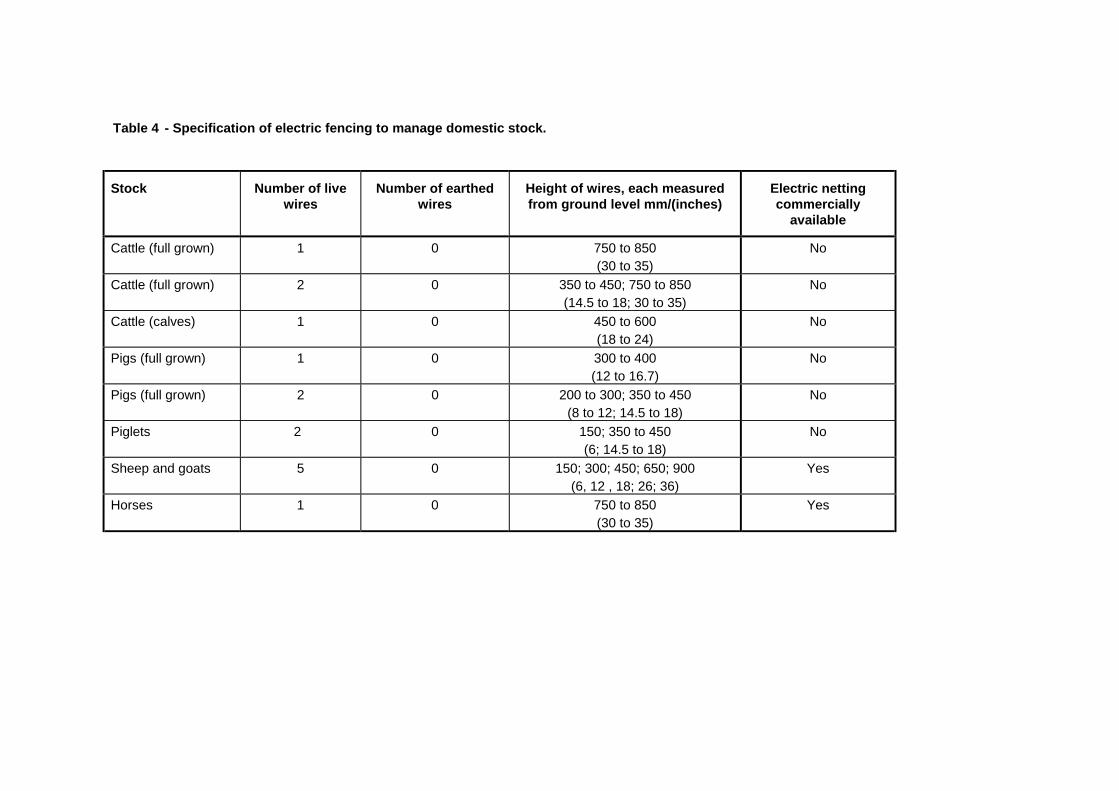
Table 4 - Specification of electric fencing to manage domestic stock.
Stock Number of livewires
Number of earthedwires
Height of wires, each measuredfrom ground level mm/(inches)
Electric nettingcommercially
available
Cattle (full grown) 1 0 750 to 850(30 to 35)
No
Cattle (full grown) 2 0 350 to 450; 750 to 850(14.5 to 18; 30 to 35)
No
Cattle (calves) 1 0 450 to 600(18 to 24)
No
Pigs (full grown) 1 0 300 to 400(12 to 16.7)
No
Pigs (full grown) 2 0 200 to 300; 350 to 450(8 to 12; 14.5 to 18)
No
Piglets 2 0 150; 350 to 450(6; 14.5 to 18)
No
Sheep and goats 5 0 150; 300; 450; 650; 900(6, 12 , 18; 26; 36)
Yes
Horses 1 0 750 to 850(30 to 35)
Yes
Electric Fence Reference Manual
Defra Research and Development Surveillance Report 607 22
CattleA single wire is usually sufficient but a second wire can be added if any difficulty isexperienced in containing particular individuals. The height of the wire should be variedaccording to the height and age (i.e. full grown or calf) of the breed being managed. Thespecification for a ‘grassfence’ is two parallel fences 60 cm (2 ft) apart, each with wires atabout 350 and 650 mm (1 and 2 ft) above the ground.
PigsAs with cattle, a single wire is usually sufficient for full-grown pigs but a second can be addedif any difficulty is encountered. Piglets can be more of a problem and the lower electrified wiremust be closer to the ground to try to contain them.
Sheep and goatsFour or five wires are generally recommended to manage sheep and goats.
HorsesOne wire is usually sufficient to manage horses. Polytape is being used more frequently as theconductor, mainly because it is highly visible and because the chance of injury to horses isless than with the use of galvanised wire.
Specifications for wild mammalsElectric fencing has been used to manage many wild mammals, with rabbits being thesmallest of the species targeted. Some species, mainly deer, appear to be very resistant toelectrical shock, because of the poor conductivity of their hooves and insulation properties oftheir coat. Therefore the use of electric fencing to deter these species appears to be limited atpresent. More wires are needed to manage wild mammals than domestic stock and metalwire is preferable to polywire. However, a range of commercially available polywire electricnetting fences are also available to manage some species and all have been found to beeffective. Details of suppliers are given in Appendix 1. It is extremely important to ensure thatthe wires are sufficiently well strained to avoid variation in wire height and to ensure goodcontact when animals push against them. The specification for each species, including deer,is given in Table 5. The decision to use electric fencing will, of course, involve comparing thecost-effectiveness of this and other methods of wildlife management, including conventionalunelectrified fencing, with the estimated costs of any damage being caused. In doing thesecomparisons, it should be remembered that fencing materials are likely to last between 5 and10 years if well maintained.
RabbitsA series of enclosure and field trials has been conducted to develop the recommendedspecification (as shown in Table 5). The earthed wire has been found essential to preventrabbits crawling under the fence. Rabbits have only rarely been found to dig burrows underelectric fences.
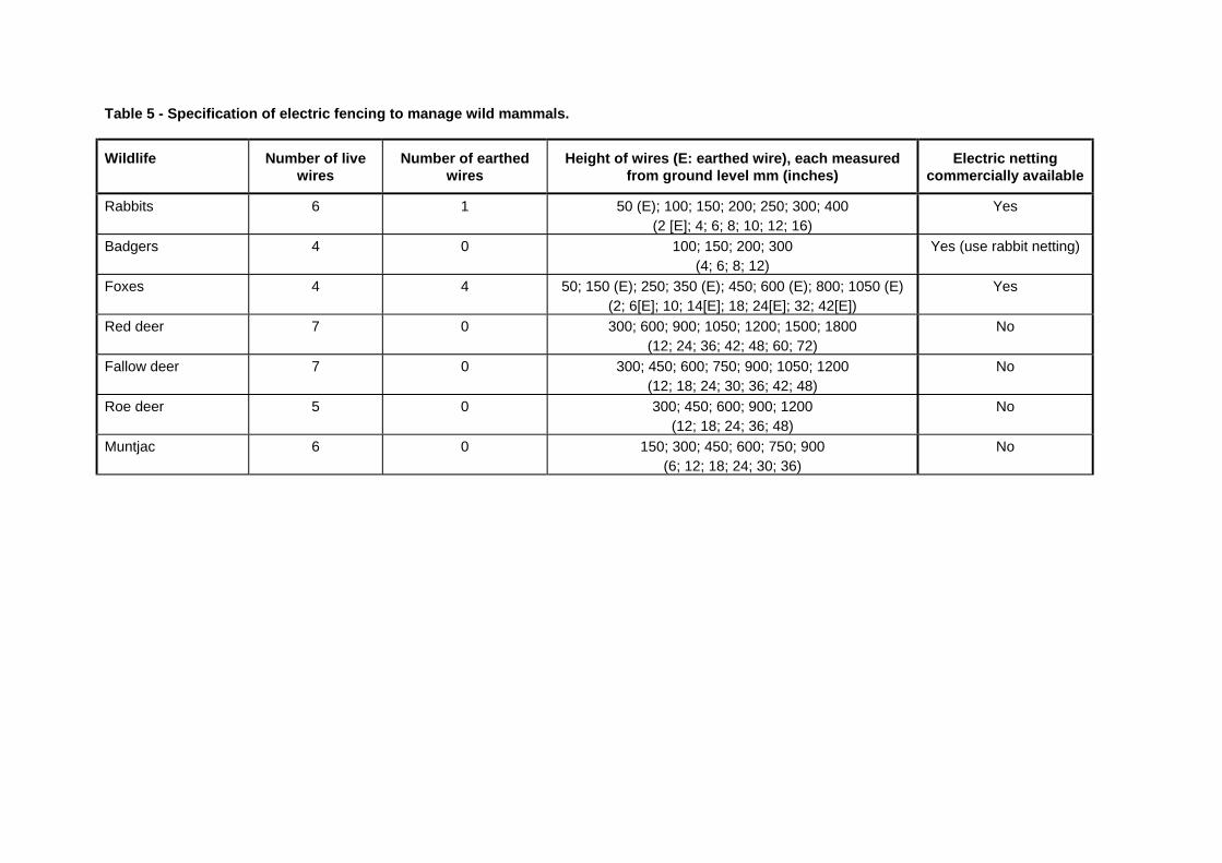
Table 5 - Specification of electric fencing to manage wild mammals.
Wildlife Number of livewires
Number of earthedwires
Height of wires (E: earthed wire), each measuredfrom ground level mm (inches)
Electric nettingcommercially available
Rabbits 6 1 50 (E); 100; 150; 200; 250; 300; 400(2 [E]; 4; 6; 8; 10; 12; 16)
Yes
Badgers 4 0 100; 150; 200; 300(4; 6; 8; 12)
Yes (use rabbit netting)
Foxes 4 4 50; 150 (E); 250; 350 (E); 450; 600 (E); 800; 1050 (E)(2; 6[E]; 10; 14[E]; 18; 24[E]; 32; 42[E])
Yes
Red deer 7 0 300; 600; 900; 1050; 1200; 1500; 1800(12; 24; 36; 42; 48; 60; 72)
No
Fallow deer 7 0 300; 450; 600; 750; 900; 1050; 1200(12; 18; 24; 30; 36; 42; 48)
No
Roe deer 5 0 300; 450; 600; 900; 1200(12; 18; 24; 36; 48)
No
Muntjac 6 0 150; 300; 450; 600; 750; 900(6; 12; 18; 24; 30; 36)
No
Electric Fence Reference Manual
Defra Research and Development Surveillance Report 607 25
BadgersA series of field trials has been run to develop the recommended specification which has beenused to exclude badgers from small plots and entire fields. Again, badgers have rarely beenrecorded digging under electric fences.
FoxesAs for rabbits and badgers, enclosure trials have been conducted to develop therecommended specification. The use of alternating live and earthed wires was foundnecessary to prevent foxes crossing fences by jumping through the wires.
DeerAgain, to test the effectiveness of electric fencing against roe, fallow and muntjac deer, aseries of enclosure trials has been conducted. The electric fence specifications found to bemost effective against each of the three deer species were all less successful than the bestnon-electric wire mesh netting deer fence specifications. Therefore, the potential use ofelectric fencing to control these deer is limited and is not recommended except whereconventional fencing cannot be used. There have been no successful UK field trials of the reddeer fence specification developed in New Zealand and currently used in some areas in theUK.
Electric Fence Reference Manual
Defra Research and Development Surveillance Report 607 26
CHAPTER 4
Safety Aspects
All electric fences must be installed and operated in a way that ensures there is no electricalhazard to people, animals or their surroundings. The fence construction must not risk theentanglement of animals or people.
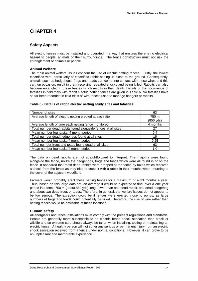
Animal welfareThe main animal welfare issues concern the use of electric netting fences. Firstly, the lowestelectrified wire, particularly of electrified rabbit netting, is close to the ground. Consequently,animals such as hedgehogs, frogs and toads can come into contact with these wires and thiscan, on occasion, result in them receiving repeated shocks and being killed. Rabbits can alsobecome entangled in these fences which results in their death. Details of the occurrence offatalities in field trials with rabbit electric netting fences are given in Table 6. No fatalities haveso far been recorded in field trials of wire fences used to manage badgers or rabbits.
Table 6 - Details of rabbit electric netting study sites and fatalities
Number of sites 63Average length of electric netting erected at each site 750 m
(850 yds)Average length of time each netting fence monitored 4 monthsTotal number dead rabbits found alongside fences at all sites 27Mean number found/site/ 4 month period 0.4Total number dead hedgehogs found at all sites 16Mean number found/site/4 month period 0.25Total number frogs and toads found dead at all sites 63Mean number found/site/4 month period 1.0
The data on dead rabbits are not straightforward to interpret. The majority were foundalongside the fence, unlike the hedgehogs, frogs and toads which were all found in or on thefence. It appeared that most dead rabbits were dropped at the fence by foxes which receiveda shock from the fence as they tried to cross it with a rabbit in their mouths when returning tothe cover of the adjacent woodland.
Farmers would probably erect these netting fences for a maximum of eight months a year.Thus, based on this large data set, on average it would be expected to find, over a one yearperiod in a fence 750 m (about 850 yds) long, fewer than one dead rabbit, one dead hedgehogand about two dead frogs or toads. Therefore, in general, the welfare issues do not appear tobe too serious. The exception could be if fences were erected close to ponds, as largenumbers of frogs and toads could potentially be killed. Therefore, the use of wire rather thannetting fences would be advisable at these locations.
Human safetyAll energisers and fence installations must comply with the present regulations and standards.People are generally more susceptible to an electric fence shock sensation than stock orwildlife and so extreme care should always be taken when installing, testing or maintaining anelectric fence. A healthy person will not suffer any serious or permanent injury from an electricshock sensation received from a fence under normal conditions. However, it can prove to bean unpleasant and memorable experience.
Electric Fence Reference Manual
Defra Research and Development Surveillance Report 607 27
Safety precautionsThe following safety precautions must be observed when installing or maintaining an electricfence:• Always seek planning approval from appropriate authorities before installing a fence
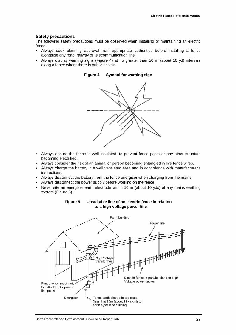
alongside any road, railway or telecommunication line.• Always display warning signs (Figure 4) at no greater than 50 m (about 50 yd) intervals
along a fence where there is public access.
Figure 4 Symbol for warning sign
• Always ensure the fence is well insulated, to prevent fence posts or any other structurebecoming electrified.
• Always consider the risk of an animal or person becoming entangled in live fence wires.• Always charge the battery in a well ventilated area and in accordance with manufacturer’s
instructions.• Always disconnect the battery from the fence energiser when charging from the mains.• Always disconnect the power supply before working on the fence.• Never site an energiser earth electrode within 10 m (about 10 yds) of any mains earthing
system (Figure 5).
Figure 5 Unsuitable line of an electric fence in relationto a high voltage power line
Farm building
Power line
Electric fence in parallel plane to HighVoltage power cables
High voltagetransformer
Fence earth electrode too close(less that 10m [about 11 yards]) toearth system of building
Energiser
Fence wires must notbe attached to powerline poles
Electric Fence Reference Manual
Defra Research and Development Surveillance Report 607 28
• Never connect more than one energiser to the same fence.• Never electrify barbed wire.• Never install a fence under and parallel to an overhead power line as the induced voltage
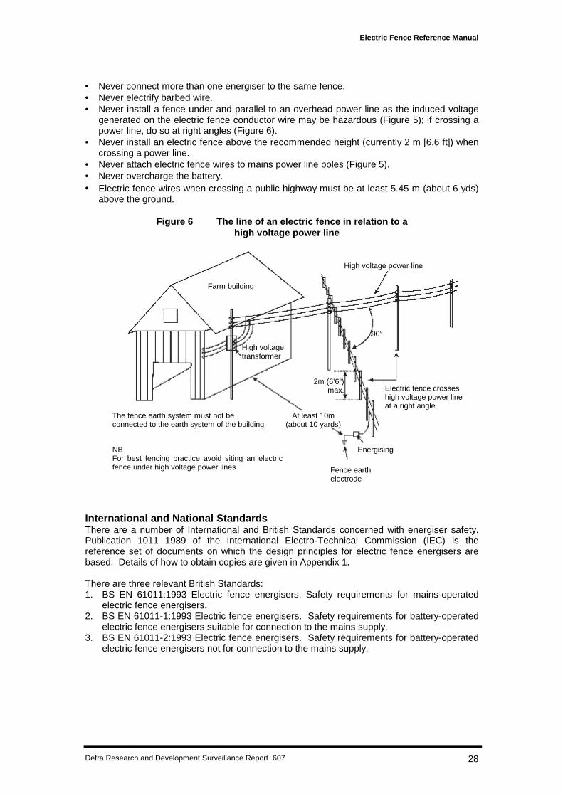
generated on the electric fence conductor wire may be hazardous (Figure 5); if crossing apower line, do so at right angles (Figure 6).
• Never install an electric fence above the recommended height (currently 2 m [6.6 ft]) whencrossing a power line.
• Never attach electric fence wires to mains power line poles (Figure 5).• Never overcharge the battery.• Electric fence wires when crossing a public highway must be at least 5.45 m (about 6 yds)
above the ground.
Figure 6 The line of an electric fence in relation to ahigh voltage power line
International and National StandardsThere are a number of International and British Standards concerned with energiser safety.Publication 1011 1989 of the International Electro-Technical Commission (IEC) is thereference set of documents on which the design principles for electric fence energisers arebased. Details of how to obtain copies are given in Appendix 1.
There are three relevant British Standards:1. BS EN 61011:1993 Electric fence energisers. Safety requirements for mains-operated
electric fence energisers.2. BS EN 61011-1:1993 Electric fence energisers. Safety requirements for battery-operated
electric fence energisers suitable for connection to the mains supply.3. BS EN 61011-2:1993 Electric fence energisers. Safety requirements for battery-operated
electric fence energisers not for connection to the mains supply.
Farm building
High voltagetransformer
High voltage power line
Electric fence crosseshigh voltage power lineat a right angle
2m (6’6”)max.
Energising
Fence earthelectrode
At least 10m(about 10 yards)
90°
The fence earth system must not beconnected to the earth system of the building
NBFor best fencing practice avoid siting an electricfence under high voltage power lines
Electric Fence Reference Manual
Defra Research and Development Surveillance Report 607 29
CHAPTER 5
Fence construction: techniques and best practice
This chapter describes construction techniques and best practice for all the components thatare needed to achieve fencing suitable for the chosen site. The materials to be used toconstruct the fence can be selected from those described in Chapter 1 and listed in Table 2,once the line of the fence has been decided and the general fence specification chosen.Factors to be considered in the specification are: height, mesh or line-wire, number of wiresand spacing, the distance between stakes and whether the fence is to be a temporary orpermanent structure.
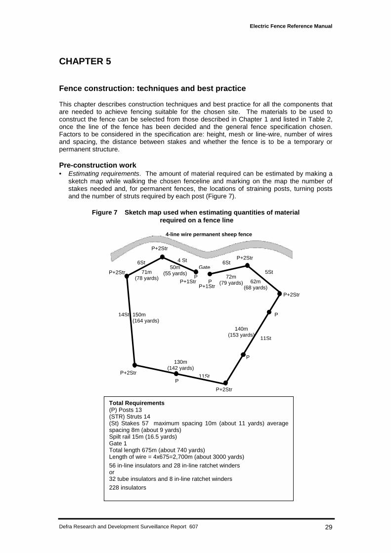
Pre-construction work• Estimating requirements. The amount of material required can be estimated by making a
sketch map while walking the chosen fenceline and marking on the map the number ofstakes needed and, for permanent fences, the locations of straining posts, turning postsand the number of struts required by each post (Figure 7).
Figure 7 Sketch map used when estimating quantities of material required on a fence line
P+1Str
P+2Str
P+2Str
P+2Str
P+2Str
14St 150m(164 yards)
P
P
P
130m(142 yards)
140m(153 yards)
62m(68 yards)
71m(78 yards)
50m(55 yards)
72m(79 yards)
11St
11St
5St
P+2Str
P+2Str
6St
PPP+1Str
6StGate
4-line wire permanent sheep fence
4 St
Total Requirements(P) Posts 13(STR) Struts 14(St) Stakes 57 maximum spacing 10m (about 11 yards) averagespacing 8m (about 9 yards)Spilt rail 15m (16.5 yards)Gate 1Total length 675m (about 740 yards)Length of wire = 4x675=2,700m (about 3000 yards)
56 in-line insulators and 28 in-line ratchet windersor32 tube insulators and 8 in-line ratchet winders
228 insulators
Electric Fence Reference Manual
Defra Research and Development Surveillance Report 607 30
• Distribution of materials. The next operation, the distribution of the materials along thefenceline, should be done with a vehicle. Where this is not possible, carefully sited dumpsof materials should be placed within easy reach of the fenceline to reduce the distance thematerial has to be carried by hand. A single dump at the beginning of a fenceline shouldbe avoided. If possible, the distribution of materials should be done by those who aregoing to erect the fence. A two-person fencing team is recommended as the mostefficient.
Fence construction principlesThe construction of the fence should be based on the principles illustrated in Figure 1. Anearth electrode only system is a fence that does not have either an earth-returning wire orearth line wires and relies on the current flow to the energiser earth being passed through theground (see Earthing in Chapter 1). These systems are generally associated with temporaryfencing and are only used with permanent fencing on sites where the soil remains dampthroughout the year. Temporary fences will generally be powered by battery-operatedenergisers.
It is recommended that permanent fences are constructed as earth electrode plus earth-returnwire systems. The addition of earthed line wires is an option and will depend on the speciesbeing managed.
Setting-up the energiser and charging systemInstalling the energiserPermanent fences may be powered by either mains or battery powered energisers. Mainspowered energisers should be installed under cover, near to the mains supply and out ofreach of children. They should also be sited away from flammable materials and away fromthe risk of mechanical damage. Battery powered energisers are sited close to the fence, atany convenient place along the fence line and on the opposite side of the fence to the animalsbeing managed. The energiser should be installed off the ground to protect it from insectsand moisture. Small dry cell battery energisers may be clipped directly on to the fence. Wetcell batteries should be housed in a ventilated, locked weatherproof box to provide securityfrom vandalism and theft, and protection against extreme temperature changes and corrosion.
Siting batteries, charging systems and regulatorsWhen batteries are to be charged from the mains supply, access for a vehicle to and from thefence is desirable. Carrying heavy, wet cell batteries any distance by hand, particularly overrough ground, may result in backstrain, acid spillage or both and should be avoided.
Wind and solar power charging systems should be located in open areas close to the battery.Solar panels should face south and be angled towards the sun and away from any possibleshade. The angle of incident light on to the solar cell array is critical for maximum output. Theoptimum is 90° to the sun. Wind generators must be located so that they are exposed to theprevailing winds.
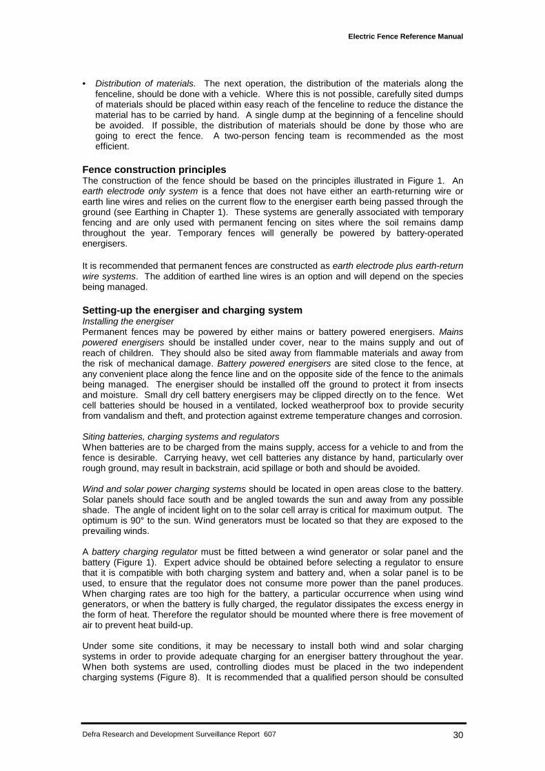
A battery charging regulator must be fitted between a wind generator or solar panel and thebattery (Figure 1). Expert advice should be obtained before selecting a regulator to ensurethat it is compatible with both charging system and battery and, when a solar panel is to beused, to ensure that the regulator does not consume more power than the panel produces.When charging rates are too high for the battery, a particular occurrence when using windgenerators, or when the battery is fully charged, the regulator dissipates the excess energy inthe form of heat. Therefore the regulator should be mounted where there is free movement ofair to prevent heat build-up.
Under some site conditions, it may be necessary to install both wind and solar chargingsystems in order to provide adequate charging for an energiser battery throughout the year.When both systems are used, controlling diodes must be placed in the two independentcharging systems (Figure 8). It is recommended that a qualified person should be consulted
Electric Fence Reference Manual
Defra Research and Development Surveillance Report 607 31
before the installation of diodes. Care must be taken to observe the correct polarity wheninterfacing wind generators, solar cells and regulators.
Lead-in wires: insulating and positioningThe lead-in wire from the energiser to the fence and from one fence to another fence shouldbe insulated and fitted with a cut-out switch. Energisers produce output pulses of severalthousand volts and low density polythene or equivalent of 1 mm wall thickness is an adequateinsulating material. Either copper or steel wire may be used as the lead-in wire and should beat least 4.0 mm2 (about 0.2 inches2) cross sectional area to ensure adequate strength andconductivity. A cable lug should be fitted, crimped or soldered at the energiser end of thelead-in wire. Where lead-in wires pass underground, double insulation is required which canbe achieved by using single insulated cable in a plastic tube or conduit. The effects of cattlehooves and tractor wheels sinking into the ground should be taken into account when decidingthe depth to which these tubes should be buried.
The provision of lightning conductors should be considered where there is historical evidenceof lightning strikes or where strikes are anticipated. A proprietary device should be used at thefence/lead-in wire junction.
Figure 8 Battery charging options
Installing an effective earthing systemThe efficiency and effectiveness of any electric fence is dependent upon an adequate andproperly installed earthing system. Many electric fence problems are avoided when goodearthing is provided. One major manufacturing company quotes that surveys have shown thatthe earthing systems on 80% of electric fence installations are ineffective.
The earthing system of an electric fence must never be connected to the main earthsystem of the mains supplies. Also, every earth rod (electrode) connected to the electricfence must be situated at least 10 m (11 yds) away from any earthing system for the protectiveearthing of buildings to ensure it is outside the resistance area of the building’s system.
A ground earth electrode should be connected via a brass bolt clamp to the earth terminal ofthe energiser with 10 mm2 (about 0.4 inches 2) PVC insulated multi-strand copper cable with across-section area of not less than 4.0 mm2 (about 0.2 inches2). The energiser should belocated as near to the fence as is practical to ensure the copper connecting cable is theminimum possible length. The electrode (copper-coated steel of 20 mm [about 1 inch]minimum diameter) should be driven into the ground to a depth of approximately 2 m (about 6ft), if possible, but not less than 1 m (about 3 ft). It should be positioned as close as possibleto, but certainly within 5 m (about 5 yds) of, the fence. Galvanised steel electrodes may beused on temporary fencing and for the earth electrode on earth return wire systems. The
MainsCharger
Battery
or
Windgenerator
and/or
Solarpanel
Voltageregulator
* If both wind and solar are to be used together controllingdiodes are required but a qualified person should beconsulted before installation.
Electric Fence Reference Manual
Defra Research and Development Surveillance Report 607 32
earth electrode of the fence should be installed, if possible, where the soil is damp to ensure agood contact. On ground with low moisture retaining properties, two electrodes screwedtogether may be necessary to enable the earth electrode to be driven to a greater depth. Aninadequate earth attached to a battery powered energiser may result in a proportion of thefence pulse appearing on the battery terminals.
Erecting the fence: post, wires and insulatorsThe posts and stakes of an electric fence function to support the conducting line wires ornetting. It is the shock sensation felt by the animal when it touches a conducting wire thatmakes the barrier effect and not the physical strength of the fence.
Temporary fencesWhen constructing temporary fences, which are generally erected in relatively short andstraight lengths, the posts only need to be strong enough to withstand the weight of theconducting wires or netting and the tension put on them.
Posts and stakes. The posts and stakes of a temporary fence are driven into the ground;there is often a pre-marked point on stakes to indicate the depth to which this should be done.Their spacing will depend on the holding ability of the soil and the number of conductor wirespresent, but as a general rule they will be between 3 and 5 m (about 3-5 yds) apart.
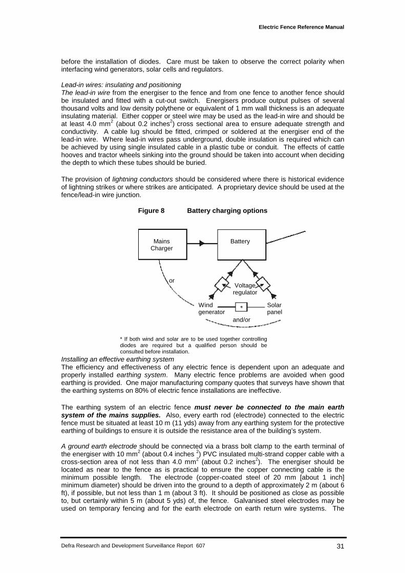
Conducting wires. The conducting wires will be either 1.6 mm or 2 mm (about 0.1 inches)steel or aluminium, polytape or polywire or polywire net. Polywire and polywire netting arehand tensioned. The other types of conductor wires are tensioned using wire strainers orratchet winders (Figure 9 and Plate 1) to a strain that is just sufficient to keep the wires taut.
Figure 9 In-line rachet winder in position
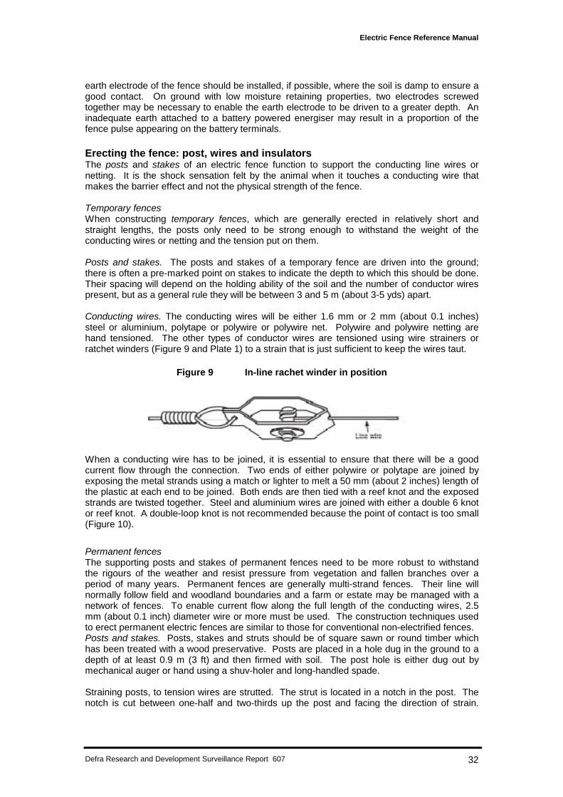
When a conducting wire has to be joined, it is essential to ensure that there will be a goodcurrent flow through the connection. Two ends of either polywire or polytape are joined byexposing the metal strands using a match or lighter to melt a 50 mm (about 2 inches) length ofthe plastic at each end to be joined. Both ends are then tied with a reef knot and the exposedstrands are twisted together. Steel and aluminium wires are joined with either a double 6 knotor reef knot. A double-loop knot is not recommended because the point of contact is too small(Figure 10).
Permanent fencesThe supporting posts and stakes of permanent fences need to be more robust to withstandthe rigours of the weather and resist pressure from vegetation and fallen branches over aperiod of many years. Permanent fences are generally multi-strand fences. Their line willnormally follow field and woodland boundaries and a farm or estate may be managed with anetwork of fences. To enable current flow along the full length of the conducting wires, 2.5mm (about 0.1 inch) diameter wire or more must be used. The construction techniques usedto erect permanent electric fences are similar to those for conventional non-electrified fences.Posts and stakes. Posts, stakes and struts should be of square sawn or round timber whichhas been treated with a wood preservative. Posts are placed in a hole dug in the ground to adepth of at least 0.9 m (3 ft) and then firmed with soil. The post hole is either dug out bymechanical auger or hand using a shuv-holer and long-handled spade.
Straining posts, to tension wires are strutted. The strut is located in a notch in the post. Thenotch is cut between one-half and two-thirds up the post and facing the direction of strain.
Electric Fence Reference Manual
Defra Research and Development Surveillance Report 607 33
The distance between straining posts will be dictated by the shape and size of the area to befenced.
Intermediate posts or stakes are driven into the ground to a depth of at least 0.6 m (2 ft). Themaximum distance between stakes will be 3 m (about 3 yds) when 3.15 mm (about 0.1 inch)medium-tensile steel conducting wires are to be used and 10 m (about 10 yds) for 2.5 mm(about 0.1 inch) high-tensile and 2.65 mm (about 0.1 inch) spring-steel wire.
Figure 10 Wire joining
Conducting wires. The conducting wires are tensioned between two straining posts. First, thewire should be uncoiled from the roll using a wire dispenser. If a dispenser is not used, thewire can be damaged and, as a result, may subsequently fracture. The wire is terminated atand insulated from a straining post with either an in-line insulator (Figure 2) or a tube insulatorwith a reinforcing metal strip. The metal strip must be positioned between the wire and thepost. The wire is then strained to a second post using a hand-operated wire strainer. It isimportant that the type of strainer used does not damage the wire. For example, the 'Monkey'type strainer is particularly suited to straining high-tensile and spring-steel wire but notmedium-tensile wire. Experience will tell the fence erector how much strain has to be put onthe wire to allow it to be raised and lowered over undulations in the ground and also to ensurethat not too much stress is left on the insulators. When the wire is strained to the requiredtension, it is secured to and insulated from the straining post. An in-line ratchet winder (Figure9) may be fitted into each line wire to assist future fence maintenance operations.
Joins in the wire should be made either by knotting (Figure 10) or with a double crimp sleevejoiner.
InsulatorsThe conductor line wires should be secured to and insulated from wooden intermediate postsor stakes with insulators to prevent current leakage to earth. Insulators are not required if the
Double-loop knot
Double-six knot
Open double loop isunsuitable for joiningconductor wires(insufficient contactbetween the two wires)
Reef-knot
Nut and bolt clamp
Electric Fence Reference Manual
Defra Research and Development Surveillance Report 607 34
stakes are plastic or glassfibre. It is recommended that only insulators that are designed andmanufactured specifically for electric fencing (see Chapter 1) should be used and thatmaterials such as hose pipe and empty fertiliser bags should be avoided. Care must be takenwhen securing insulators with nails that the hammer does not strike and damage the insulator.
The fence erector can test the quality of the insulation using an electric insulation testerbetween the secured conductor wire and the supporting post. A measurement of resistance istaken from the wire to a point on the post 150 mm (6 inches) from the wire and a reading of25–200 megaohms is required.
Existing fencesConducting wires can be added to new, unelectrified fences and walls to improve theireffectiveness and to existing, and often ageing, unelectrified fences to extend their life. Wiresadded to fences are generally attached with off-set insulators (Figure 3) or insulated brackets.The wire should be fixed at about two-thirds the height of the animal being controlled and thebrackets should be spaced about 10 m (10 yds) apart. These off-set wires are sometimescalled scare wires.
Existing fences and walls should be inspected prior to the addition of electric fence wires. Anystraining point not appearing to be strong enough for the proposed tension on the wires shouldbe strain-tested to 150% of the expected tension. The wires on an existing fence should beinspected for corrosion. Sections of fence where there is significant corrosion andconsequently a risk of fracture, which would short the electric fence, should be removed andreplaced.
Remember ... the addition of electric fence wires to an existing barbed wire fence is notrecommended.
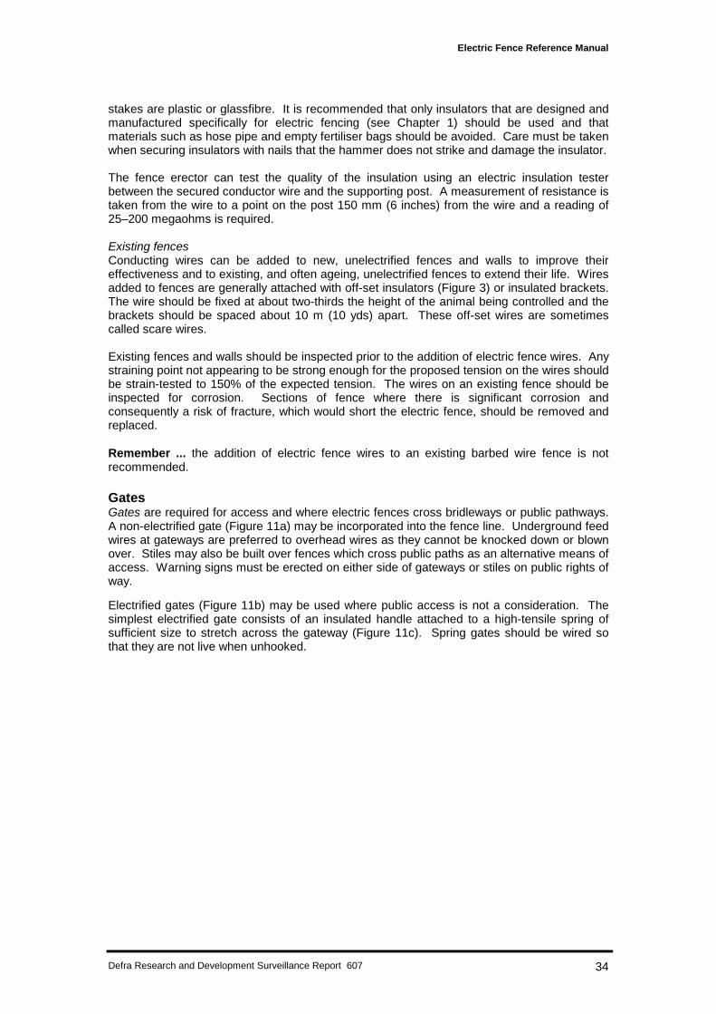
GatesGates are required for access and where electric fences cross bridleways or public pathways.A non-electrified gate (Figure 11a) may be incorporated into the fence line. Underground feedwires at gateways are preferred to overhead wires as they cannot be knocked down or blownover. Stiles may also be built over fences which cross public paths as an alternative means ofaccess. Warning signs must be erected on either side of gateways or stiles on public rights ofway.
Electrified gates (Figure 11b) may be used where public access is not a consideration. Thesimplest electrified gate consists of an insulated handle attached to a high-tensile spring ofsufficient size to stretch across the gateway (Figure 11c). Spring gates should be wired sothat they are not live when unhooked.
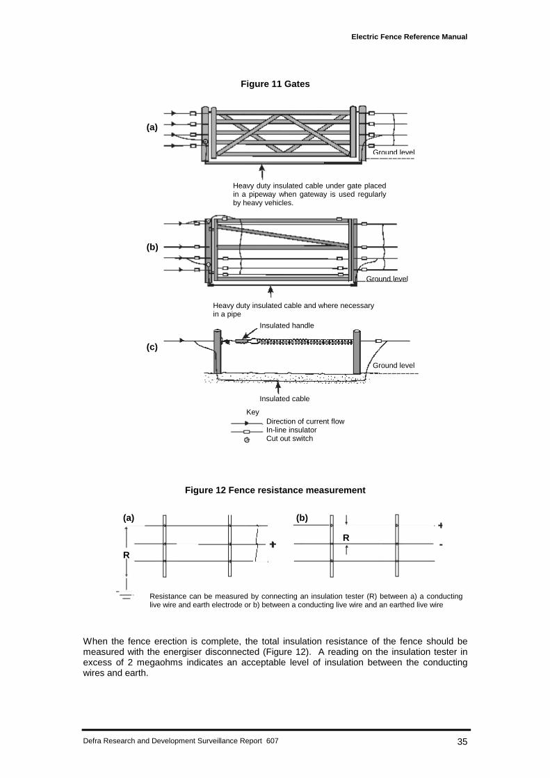
Electric Fence Reference Manual
Defra Research and Development Surveillance Report 607 35
Figure 11 Gates
Figure 12 Fence resistance measurement
When the fence erection is complete, the total insulation resistance of the fence should bemeasured with the energiser disconnected (Figure 12). A reading on the insulation tester inexcess of 2 megaohms indicates an acceptable level of insulation between the conductingwires and earth.
Ground level
Ground level
Ground level
Heavy duty insulated cable under gate placedin a pipeway when gateway is used regularlyby heavy vehicles.
Heavy duty insulated cable and where necessaryin a pipe
Insulated handle
Insulated cable
KeyDirection of current flowIn-line insulatorCut out switch
(a)
(b)
(c)
Resistance can be measured by connecting an insulation tester (R) between a) a conductinglive wire and earth electrode or b) between a conducting live wire and an earthed live wire
R
R
(a) (b)
Electric Fence Reference Manual
Defra Research and Development Surveillance Report 607 36
CHAPTER 6
Fence siting
Before a final decision can be made on the actual siting of the electric fence, the followingmain issues have to be taken into consideration:• planning aspects• geography of the area• ratio of fence length to area enclosed• seasonal and climatic influences
Planning aspectsWhen planning the line of an electric fence, there are a number of aspects that need to betaken into account, particularly in relation to power lines and telephone lines. The issues ofpower lines, electric fencing and safety have already been discussed in Chapter 4. Electricfences can cause interference on telephone lines and it is the legal responsibility of thelandowner to prevent any interference occurring. Therefore, fences should not be sited undertelephone wires or parallel to underground telecommunication cables. Similarly, electricfences should be sited away from radio aerials. It is recommended that when new, permanentelectric fences, and particularly boundary fences, are being planned, all interested partiesshould be consulted to ensure that the proposed fence line is acceptable to all.
Geography of the areaThe line a permanent fence may be required to take is often rigidly defined by law or thegeography of the area, and allows for little subsequent variation. Where this is not so, it maybe possible to make worthwhile savings by straightening out the line to eliminate one or morecorner posts. The ease of digging-in and firming the straining posts should also be consideredand waterlogged areas and shallow soils over rock avoided. Where possible, avoid fencing onexcessively undulating ground, where it may be difficult to prevent a multi-strand electric fencelifting off the ground.
Ratio of length to area enclosedThe length of fence in relation to the area to be enclosed must also be taken into account.The best practical shape, to give the lowest ratio of fence length to area enclosed, is a squareand the larger the area fenced, the lower the cost per hectare. However, very large areas maybe unmanageable if animals break through the fence.
Seasonal and climatic influencesClimatic conditions should also be considered. For example, in a valley that is subjected toregular drifting snow, a fence placed some yards up the hillside, rather than in the valleybottom, may miss snowdrifts. However, care should be taken when fencing along a steepslope that animals approaching from the higher side are not able to jump over the fence.
Remember ... every opportunity must be taken to gather and consider all the availablerelevant local knowledge before a fence line is agreed and the fence is erected. Relocation ofa permanent electric fence after completion is expensive. A flow chart to act as a guide andchecklist on the order of tasks to be undertaken is given in Figure 13.
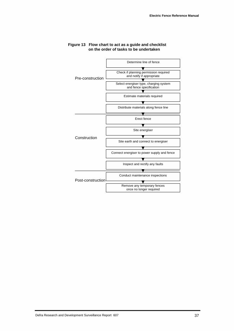
Electric Fence Reference Manual
Defra Research and Development Surveillance Report 607 37
Figure 13 Flow chart to act as a guide and checkliston the order of tasks to be undertaken
Check if planning permission requiredand notify if appropriate
Estimate materials required
Determine line of fence
Select energiser type, charging systemand fence specification
Distribute materials along fence line
Erect fence
Site energiser
Site earth and connect to energiser
Connect energiser to power supply and fence
Inspect and rectify any faults
Conduct maintenance inspections
Remove any temporary fencesonce no longer required
Pre-construction
Construction
Post-construction
Electric Fence Reference Manual
Defra Research and Development Surveillance Report 607 38
CHAPTER 7
Fence maintenance
Once erected, electric fences cannot be forgotten. Routine inspections are required to ensurethat they continue to operate effectively. Inspections are required to check, for example, fencepower in order to decide when it is appropriate to change batteries and to examine the fencefor any problems which could reduce its effectiveness, such as sagging wires, debris orvegetation growing against it. This chapter provides recommendations on the frequency ofinspections based on studies of behaviour at fences, as well as the items to be checked ateach inspection, and concludes with some important advice on out-of-use fences.
Animal behaviour at fencesMost animals learn to avoid objects associated with unpleasant experiences: this is calledconditioned avoidance (see also Animal training and management in Chapter 3). If theexperience is sufficiently unpleasant, then the effect can be immediate and long-lasting andthis can be the case with mammals receiving a shock in a sensitive area such as the nose. Instudies with cattle, sheep and goats most shocks were received during the first few days ofenclosure. Thereafter, very few were received. Some cattle avoided the fences without everhaving touched them, presumably by copying others or by witnessing their reactions afterhaving touched the fence: this is called socially learned avoidance. There have beensuggestions that cattle may not touch an electric fence because they can sense when it isoperating, possibly by detecting an odour, the electromagnetic field, or ozone generatedaround the wires. However, at present, there is no conclusive research evidence in support ofthese views.
In studies undertaken to exclude wild, nocturnal animals such as rabbits, foxes and badgers,most shocks were again received during the first few days after fence erection. Thereafter,most animals altered their ranging behaviour to avoid the fences and far fewer shocks werereceived. In those studies where individuals have been marked, all received shocks.Therefore, there was no evidence of socially learned avoidance, as would be expected forthese animals as they do not move around at night in groups.
Implications of behaviour for the frequency of maintenance inspectionsSince most contacts with fences appear to occur shortly after fence erection and someanimals learn to avoid fences without receiving shocks, it follows that animals may continue toavoid the fence even if the power were to be accidentally cut off. Therefore, daily inspections,which are sometimes recommended to forestall crossings as a result of power failure, may beessential only during the first few days after erection. For example, when power wasdisconnected to a fence containing 24 cattle in a 10 ha (about 25 acres) enclosure after threeweeks of electrification, it took about a further week before cattle crossed the fence. Whenpower was disconnected after only one night’s electrification to a fence containing differentgroups of five wild rabbits in a 0.1 ha (about 0.25 acres) enclosure, all crossed on the nightpower was disconnected. By contrast, when the fence had been electrified for one week priorto power being disconnected it then took a further week before rabbits crossed. Extending theperiod of electrification to three weeks, prior to disconnection, made no difference as it stilltook a further week. Similarly, electric fences used to exclude free living badgers for twoweeks from plots containing an attractive food on commercial farms continued to excludethem for up to three weeks after power was disconnected.
These results confirm that a conditioned avoidance reaction is not immediately lost whenpower to a fence is cut off and that daily inspections should not be necessary after an initialperiod of conditioning. More research would be required, however, before species-specificrecommendations could be made for the timings of maintenance inspections of electricfences. This would involve, for example, determining the duration of the initial training periodsfor stock and investigating factors which could influence it and the time taken for conditioning
Electric Fence Reference Manual
Defra Research and Development Surveillance Report 607 39
to be lost. When managing domesticated mammals, stocking density will obviously be animportant factor; when managing free-living wild mammals, ranging and territorial behaviour,and social structure will be important factors. Results obtained from these kinds ofexperiments, combined with recent developments in automated fault detection equipmentwhich can be attached to the fence, could further contribute to considerable reductions inmaintenance costs.
Fence inspections: when and what to checkIt is recommended that electric fences should be inspected daily during the first week afterfence erection to ensure that they are continuously electrified. This will ensure that animalshave the maximum opportunity to encounter the live fence and receive a shock during thisperiod. Thereafter, inspections should be at least at weekly intervals. However, more frequentinspections may be necessary if the consequences of animals crossing the fence areconsidered to be serious.
At each inspection, the connections between the battery and energiser, the energiser andearth rod and the energiser and fence should be checked. The electrical pulse should bechecked at each end of the fence and on each conductor wire on multi-wire fences. If thesystem contains earthed wires, the connection between these wires and the earth rod shouldbe checked and the voltage between live and earthed wires should also be measured. Thefence line should be walked to check for physical damage to insulators or evidence of ‘arcing’(charring of the insulation material) which indicates a break-down of the insulation. If theenergiser is switched on, the arcing may be heard and in low light conditions, the sparksgenerated may be seen. In an electric netting fence, each horizontal wire should be checkedat intervals of about 100 m (about 100 yds) to ensure that no wire has been bitten through atmore than one point in each roll; if this does occur, the section of wire between the two breakswill not be carrying current. Connections between adjoining rolls of netting should also bechecked. The entire fence should be inspected and any debris removed. The need forherbicide applications should be considered when vegetation begins to grow against thefence, causing leakage and hence a reduction in voltage.
Monitoring electrical efficacyThe following two meters are very useful for determining electrical efficacy. An electrostaticvoltage meter calibrated in kilovolts (kV), usually 0 to 10 kV, provides an indication that thefence is in working order, and can be used to monitor levels of deterioration. Therefore, theaim should be to obtain the highest output possible from the energiser being used. As a guide,the voltage should be maintained at between 4 and 6 kV. If it drops below that level, thebattery should be changed, if appropriate, and the fence line inspected to rectify any faults.Voltage meters do not indicate the energy available to deliver an effective shock.
A joulemeter calibrated in either millijoules (mJ) or joules(J), usually 0–1000mJ or 0–10J, isused to measure the energy available on the fence. This measurement provides a clearerindication of the shock sensation that will be experienced by an animal contacting theconductor wires and therefore the efficacy of the fence.
Identifying and rectifying faultsThe following systematic approach should be adopted to identify and rectify faults.First check the energiser. If it is not ticking it may be because:• it is not switched on;• the mains supply has failed;• the fuse has blown;• the battery needs charging; or• there is a lose or broken connection between the power supply and the energiser.If no fault is found the problem will be in the energiser. This can be confirmed by substitutingwith another.
If the energiser is ticking but there is no output it may be because:
Electric Fence Reference Manual
Defra Research and Development Surveillance Report 607 40
• the battery needs charging;• the lead-in wire to the fence has a loose or broken connection; or• the energiser is faulty.If the energiser is found to be at fault it must be returned to the manufacturer for repair. Donot attempt to repair it yourself.
If the energiser is found to be operating satisfactorily, then check the fence for:• a loose or broken connection to earth;• a leakage of current to earth which may be due to vegetation or debris touching the
conductor wires or to damaged or poor insulators (it may be necessary to check eachinsulator in turn for evidence of arcing or for any wire that has been dislodged); or
• a short to earth which may be caused by a broken conductor wire or a foreign object of lowelectrical resistance bridging the gap between the conductor wire and earth.
All components found to be faulty, such as insulators, should be replaced and discarded toensure they are not inadvertently used again. Fault finding on extensive permanent fencesystems can be eased at the time of fence erection by breaking the fence into sectionsseparated by isolating switches. The section with the fault can then be identified more easily.
Out-of-use fencesTemporary electric fences should not be left unelectrified in the field for long periods of time,once the need for them has passed. Wild mammals in particular can become so accustomedto crossing such a fence that when it is switched on again, it may be less effective. Electricnetting fences can also become severely damaged by animals biting through the wires so thatsections of the netting may have to be replaced. Furthermore, there is a danger that wildmammals can become entangled in the netting and may die as a consequence. Unelectrifiedtemporary fences can also easily be damaged by machinery or stock. Vegetation can growthrough electric netting fences, making them more difficult to remove when this eventuallybecomes essential. Materials such as fence posts left on the ground can become overgrownvery quickly, be easily lost and may eventually damage tyres, harvesting equipment or othertypes of machinery.
Remember ... Once the fence, either temporary or permanent, has served its purpose, itshould be removed completely. This avoids any future hazards and makes way for betterworking practices in the future. In addition, many of the components, if carefully stored, will beavailable for future use.
Electric Fence Reference Manual
Defra Research and Development Surveillance Report 607 41
APPENDIX 1
Further reading
British Standards on electric fencing:
BS EN 61011:1993 Electric fence energisers. Safety requirements for mains-operatedelectric fence energisers;BS EN 61011-1:1993 Electric fence energisers. Safety requirements for battery-operatedelectric fence energisers suitable for connection to the mains supply; andBS EN 61011-2:1993 Electric fence energisers. Safety requirements for battery-operatedelectric fence energisers not for connection to the mains supply.
British Standards information can be obtained from:
BSI,Customer Services,389 Chiswick High Road,London,W4 4 AL(Tel: 020 8996 9001)www.bsi-global.com
Useful contact addresses
Suppliers of electric netting
Bramley & Wellesley Ltd.Unit C, Chancel Close Trading Estate,Eastern Avenue,Gloucester(Tel: 01452-300450)
EuronetsCapel FarmCapel-le-FerneFolkestoneKent(Tel: 01303-250736)
Electranets Ltd.31 Westfield Ave.BrockworthGloucester(Tel: 01452-864320)
Renco Ltd.,Bath Road Trading Estate,StroudGloucester.(Tel: 01453-752154)