Electric Current => I Q A dQ I - School of Electrical ...petriu/Electric-Circuit.pdf · 1 A= 1 C/s...
31
I wire pipe Fig. 1 Wire carrying current I (left) and its water model (right). CURRENT AND CHARGE An electric current consists of electric charges moving in a wire. •Flow of water: [molecules/s], [l/s] •Electric current: [Ampere]=[A] Electric Current => I Electric Charge => Q I dQ dt = 1 Ampere = 1Coulomb/s DIRECT CURRENT FUNDAMENTALS
Transcript of Electric Current => I Q A dQ I - School of Electrical ...petriu/Electric-Circuit.pdf · 1 A= 1 C/s...

I
wire pipe
Fig. 1 Wire carrying current I (left)
and its water model (right).
CURRENT AND CHARGE
An electric current
consists of electric charges
moving in a wire.
•Flow of water: [molecules/s], [l/s]
•Electric current: [Ampere]=[A]
Electric Current => I
Electric Charge => Q
IdQ
dt=
1 Ampere = 1Coulomb/s
DIRECT CURRENT FUNDAMENTALS

1 A = 1 C/s = 6.3 x 10¹⁸ elementary electric charges/s
...+ +
++... ...
-
-- -
-...
+ +
++... ...
-
-- -
-
electronThe elementary electric charges
that are actually moving
are electrons which
jump between
external orbits of
adjacent atoms.
From a physical point
of view, the electric current flowing
through a wire is like a river of electrons.
However as the the electrons are “negative electric charges” (due to
some odd historical reasons!), from a technical point of view, these
flow of electrons is considered a negative current!!

Small … and big currents
Engineering Unit Prefixes
0.067 A = 67 mA
73,500 A = 73.5 kA
Prefix Abbr. Value
tera T 1012
giga G 109
mega M 106
kilo k 103
milli m 10-3
micro 10-6
nano n 10-9
pico p 10-12
femto f 10-15
atto a 10-18

IdQ
dt=
Q i t dt
t
1
0
1
= •∫ ( )
Electrical charge Q1 that flows
over the time t1 is the integral of the
current from the time zero to time t1.

I1
I2
I3
I4
Kirchhoff’s Current Law
In
n
N
=∑ =
1
0
=> Some currents should be flowing into the node
while other currents should come out of the node
•Currents flowing into the node are considered “positive.”
•Currents coming out are considered “negative.”
The indestructibility of electrical currents is expressed by
Kirchhoff’s Current Law (KCL), which states that the sum
of all the currents into a node is zero.

I1 = I2 + I3
I1
I2 I3
A current splits to enter
two parallel circuit elements
I1
I2
I3
•Currents flowing into the node are considered “positive” : I1
•Currents coming out are considered “negative”: I2 and I3.
I1 - I2 - I3 = 0KCL

CONDUCTORS, INSULATORS,
SEMICONDUCATORS, AND SUPERCONDUCTORS
CONDUCTORS ….. materials through which electric
currents flow relatively easily.
•silver (tarnishes ! =>limited practical use);
Solder an amalgam of tin & lead, having a relatively low melting
temperature, used to connect electrical components
Metals are good conductors
•gold (expensive! => used as a coating to protect other metals in connectors);
•copper and aluminum (mostly used for wiring; aluminum surface oxidizes
rapidly but it is considerably less expensive and lighter than copper);

INSULATORS …. materials that do not conduct electricity:
* vacuum * dry air* ceramics * glass * plastic *rubber*dry paper*
… very special materials which, when cooled
below their critical temperature (from a few
deg. K up to more than 1000 Kfor the “high-temperature superconductors”)
Most wires are coated with a layer of insulation to
prevent current from finding unintended paths
SUPERCONDUCTORS
…are used to generate the very strong magnetic fields required
for nuclear magnetic resonance imaging, and may even be
used in electric motors and for levitating trains.

… materials such as silicon (Si) and
germanium (Ge) which are relatively poor
conductors until they are “doped” with trace quantities of other materials
such as arsenic (As), phosphorous (P), or boron (B).
SEMICONDUCTORS
B
BORON
valence +3
atomic no. 5
Si
SILICON
valence +4, -4
atomic no. 14
P
PHOSPHORUS
valence +5
atomic no. 15
As
ARSENIC
valence +5
atomic no. 33
Al
ALUMINIUM
13
Ga
GALLIUM
31
C
CARBON
5
N
NITROGEN
7
Ge
GERMANIUM
32
GROUP III GROUP IV GROUP V
Portion of the periodic
table of the elements
near the element Silicon.

Semiconductors are used to form electronic
devices such as diodes and transistors (BJT
= Bipolar Junction Transistor).
n-Si
p-Si
n-Si
Emitter
Base
Collector
IE
IB
IC
p-Si
n-Si
p-Si
Emitter
Base
Collector
IE
IB
IC
n-Si
p-Si ID
• Impurities from Group V (P, As) are called donors as they contribute
more free electrons to the silicon, resulting in an n-type silicon (in which
the majority current carriers are electrons).
• Impurities from Group III (B) are called acceptors as they contribute more
positively charged holes to the silicon, resulting
in a p-type material (in which the majority
current carriers are holes).
Semiconductors

VOLTAGE
Water model for a steady
voltage source
+
-
Schematic symbol
for the steady
voltage source
The measurement unit for
voltage is the Volt [V].
In the water model, the electric voltage
is equivalent to the water pressure.

RESISTANCE
The magnitude of this resistance depends on the different construction
parameters of these wires and other electric circuit components:
• a small-diameter wire will offer a bigger resistance than a large-diameter one;
• a long wire will offer a bigger resistance than a short wire;
• the nature of the material also affects the amount of this resistance.
Similarly, the wires and other circuit components offer some
resistance to the passage of electric current through them.
WATER MODEL ==> Any pipe hooked up to a source of water offers
some resistance to the flow which goes through it. Different pipe
construction parameters will affect the degree of resistance. A small-
diameter pipe will offer a bigger resistance than a large-diameter one.

The measurement unit for resistance is the Ohm [ΩΩΩΩ].
Schematic symbol
Resistor’s value marked
with colored bands.
Band Significant Multiplier Tolerance
color digit
Black 0 1 -
Brown 1 10 1%
Red 2 100 2%
Orange 3 1,000 3%
Yellow 4 10,000 4%
Green 5 100,000 -
Blue 6 1,000,000 flame proof
Violet 7 10,000,000 -
Gray 8 - -
White 9 - -
Gold - 0.1 5%
Silver - 0.01 10%
No band - - 20%

Ohm’s Law
V I R= •
+ -
R = 8 Ω
V = 12 V
I = V / R = 12 V / 8 Ω = 1.5 A I = 1.5 A
Ohm’s Law states that the voltage V drop over a resistance
is equal to the value of that resistance R multiplied by the
current I which goes through it.

Kirchhoff’s Voltage Law
Vn
n
N
=∑ =
1
0
Kirchhoff’s Voltage Law (KVL) states
that the sum of all the voltages around
any closed circuit is zero.
This means that as follow around any loop in a specific direction,
some of the voltages across components will be negative and some
will be positive, but when we have closed the loop the sum of all
voltages will be zero.

# 3
+ -
- +
+ -
+ -
+ -
- +
+ -
1 V 3 V
12 V
4 V
9 V
3 V
5 V# 1 # 2
Loop #1:
1V + 5V + 3V - 9V = 0
Loop #2:
-3V + 12V - 4V - 5V = 0
Loop #3:
1V - 3V + 12 V - 4V + 3V - 9V = 0
Move around the loop
summing the voltage
drops. The sign which is
encountered first when
reaching a component
tells what to do (+ or -)
with the voltage drop over
that component.

Power
Similarly, the electric power P delivered
by a steady voltage V source providing a
current I is expressed by the formula: P I V= •
The measurement unit for power is the Watt [W].
1 W = 1 A . 1 V
WATER MODEL ==> When water flows over a water wheel to
power a mill, both the amount of water flowing (the equivalent of
the electric current) and the height of the fall (the equivalent of the
voltage) determine the power that is delivered. The product of these
two parameters gives the amount of power.

Energy
A charge moving through an electric
field in a vacuum converts the potential
energy to kinetic energy in its motion.
The quantity of energy can be
expressed by the formula: U Q V= •
The measurement unit for energy is the Joule [J].
1 J = 1 C . 1 V

Energy U can also be expressed
as an integral of the power P
over an interval of time T:
U I V T= • •
If the voltage V and current I are constant in time the energy produced
over the interval of time T is :
U I t V t d t
T
= • •∫ ( ) ( )0
1 J = 1 C . 1 V =
1A . 1 s . 1 V = 1 W . 1 s
Energy delivered by the Hydro electric utility
is measured in kilowatt-hours:
1 kWh = 1,000 W . 3,600 s = 3,600,000 J
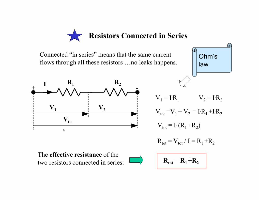
Resistors Connected in Series
Connected “in series” means that the same current
flows through all these resistors …no leaks happens.
I R1 R2
V2V1
Vto
t
+ -
V1 = I.R1
Ohm’s
law
V2 = I.R2
Vtot =V1 + V2 = I.R1 +I.R2
Vtot = I. (R1 +R2)
Rtot = Vtot / I = R1 +R2
Rtot = R1 +R2
The effective resistance of the
two resistors connected in series:

Resistors Connected in Parallel
R1 R2V
+
-
I
I2I1
Connected “in parallel” means
that the current entering the node
splits as a river that branches in
more channels.
V = I2.R2
KCL
Ohm’s
law
I1 = V / R1
I2 = V / R2
I = V / R1 + V / R2 = V. (1 / R1 + 1 / R2)
V = I1.R1
I = I1 + I2
I / V = 1 / R1 + 1 / R2
1 / Rtot = 1 / R1 + 1 / R2
RR R
R Rtot =
•
+1 2
1 2
The effective resistance:

Rtot
Generalization => “n” resistors in parallel
-
V
+ I
R1
I1
Rn
Ik
Rk
Ik
- - - - - -
I = I1+…+Ik …+In
Ik = V/Rk ; k= 1, 2, …, n
V/Rtot = V/R1+ … +V/Rk … +V/Rn
V =I . Rtot
Rtot = the effective resistance of
the n resistors in parallel:
Rk ; k =1, 2, …, n
1/Rtot = 1/R1+ … +1/Rk … +1/Rn

Power Dissipated in a Resistor
P = I . V
V = I . RP = I2 . R P = V2 / R
RI+ -
V

Schematics
wire connection no connection
(archaic)
resistor
+
-
voltage
source
current
source
terminalbattery
+
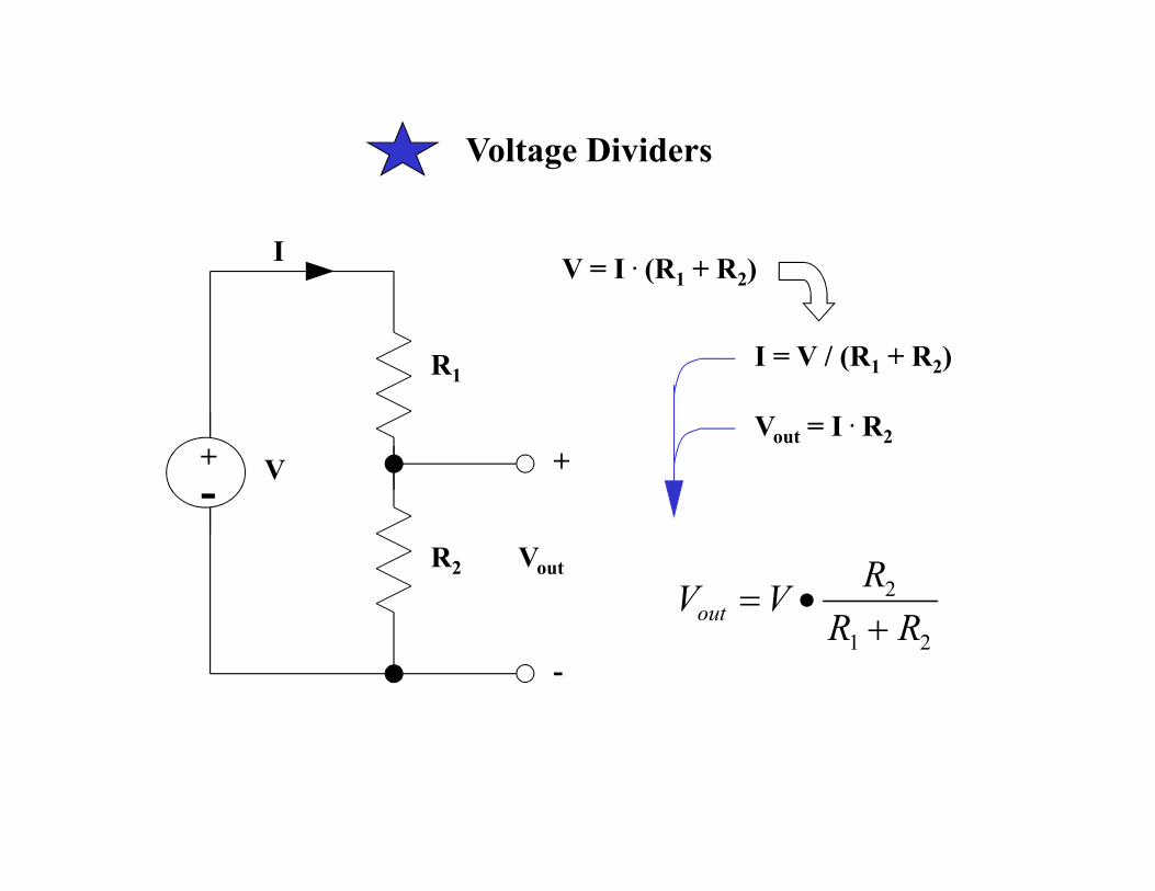
Voltage Dividers
+
-
R1
R2
V
Vout
+
-
IV = I . (R1 + R2)
Vout = I . R2
I = V / (R1 + R2)
V VR
R Rout = •
+2
1 2
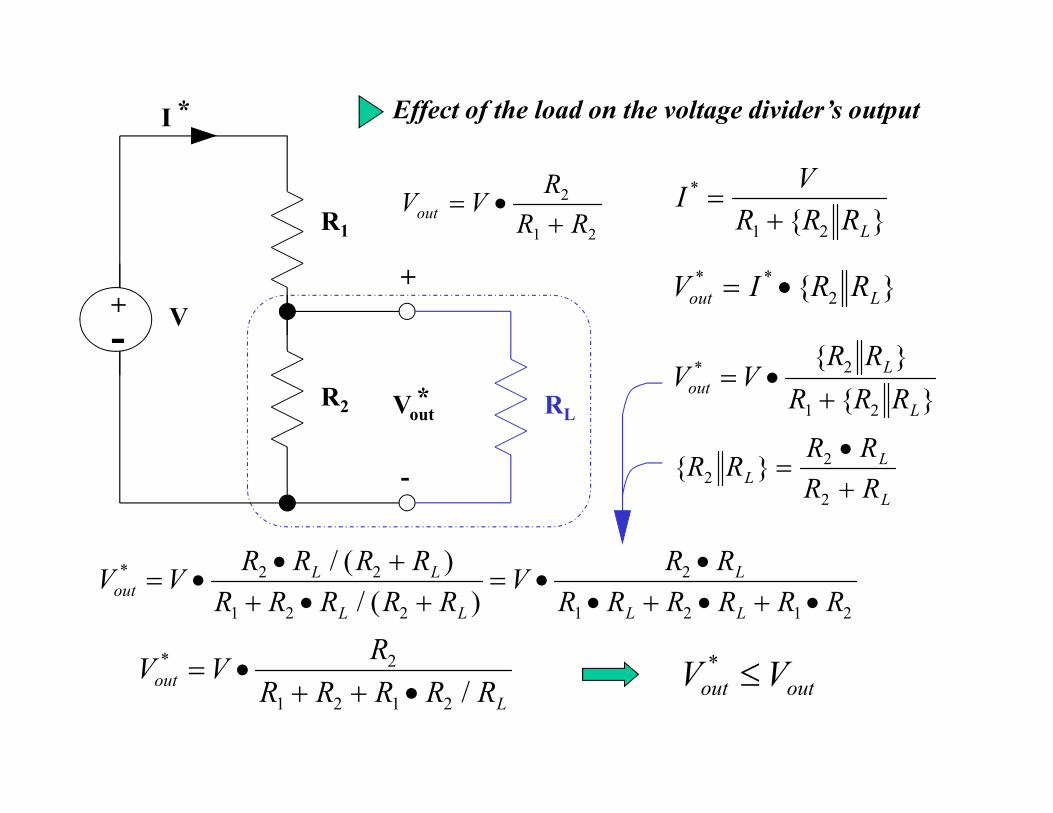
Effect of the load on the voltage divider’s output
+
-
R1
R2
V
Vout
+
-
I
RL*
*
V VR
R Rout = •
+2
1 2
R RR R
R RL
L
L
2
2
2
=•
+
IV
R R RL
*
=
+1 2
V I R Rout L
* * = • 2
V VR R
R R Rout
L
L
*
= •
+2
1 2
V VR R R R
R R R R RV
R R
R R R R R Rout
L L
L L
L
L L
* / ( )
/ ( )= •
• +
+ • += •
•
• + • + •2 2
1 2 2
2
1 2 1 2
V VR
R R R R Rout
L
*
/= •
+ + •2
1 2 1 2
V Vout out
* ≤

Ground
In the early days of the telegraph only a single wire was used to carry the
current. The return path was provided by making a connection to the
ground on both ends: emission and reception. This does make sense because
the moisture and the ion content allows the soil to conduct electricity.
The term ground has come to mean any common connection point to
which other points in an electric circuit are referenced.
• In a circuit schematic drawing all the nodes that are drawn using the same
same type of ground symbol are connected to a common conductor.This
saves having to draw all of these wires, which might clutter the schematic.
• Voltages marked on a schematic are usually referred to ground.
• Some electronic devices housed in metal enclosures or chassis make use of
what is known as a chassis ground.
Digital
ground
Analog
ground
Chassis
or earth
ground

Thevenin Equivalent Circuits/
The Thevenin equivalent circuit
can represent any collection of
DC voltage sources and resistors
as an equivalent circuit that
consists of a single voltage
VTh and a single resistor RTh.
RTh
VTh+
-
??? For any given circuit (even
a very complex one) what would
be the voltage and the resistance
which a user can see looking from
outside at these two terminals ???

• connect a voltmeter (having a very high internal resistance so it consumes
a practically negligible current from the tested circuit) across the two output
terminals to measure the open-circuit voltage, Voc ;
• replace the voltmeter with an ammeter (which has a practically negligible
internal resistance) to measure the short-circuit current, Isc ;
• calculate the Thevenin voltage, VTh= Voc, and the Thevenin resistance
RTh = VTh/Isc= Voc/Isc .
Measurement approach to find the Thevenin equivalent circuit:
N.B. - This method allows to see the effects of a load resistance across two
points in a given circuit.
- It is an easy to apply method if you have a physical circuit measure,
or if Voc and Isc can be easily calculated from the schematic.

+
-
+ -
V1
V2
R1 R2
A
B
RTh
VTh+
-
A
B
V1 = 12 V
V2 = 8 V
R1 = 6.8 Ω
R2 = 5.2 Ω
VTh = -V2 +V1 = -8V +12V = 4V
RTh= R2 + R1 = 5.2 Ω + 6.8 Ω
Example
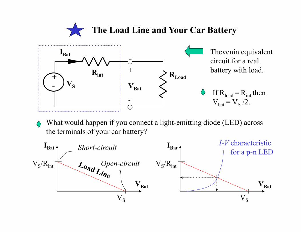
The Load Line and Your Car Battery
What would happen if you connect a light-emitting diode (LED) across
the terminals of your car battery?
Rint
VS
+
-
+
-
IBat
VBat
RLoad
Thevenin equivalent
circuit for a real
battery with load.
If Rload = Rint then
Vbat = VS /2.
VS
VS/Rint
IBat
VBat
Short-circuit
Open-circuit VS/Rint
IBat
VS
VBat
I-V characteristic
for a p-n LED