Electric Bicycle - Motorino · 4 Welcome Your new MOTORINO™ is the culmination of our decade-long...
52
Owner’s Manual Electric Bicycle
-
Upload
nguyendiep -
Category
Documents
-
view
214 -
download
0
Transcript of Electric Bicycle - Motorino · 4 Welcome Your new MOTORINO™ is the culmination of our decade-long...

Owner’s Manual
ElectricBicycle

2 MOTORINO™ ELECTRIC BICYCLE OWNER`S MANUAL
© 2013 by Greenwit Technologies Limited
Revised October 2013
All Rights Reserved
Any reprinting or unauthorized use without the written permission of Greenwit Technologies Inc. is expressly prohibited.
All trademarks remain the property of their respective owners.
Important Information About This Manual

3
Important Information About This ManualA “WARNING!” label indicates that failure to abide by the following instructions may result in serious personal injury or death to the rider or others, as well as damage to equipment.
A “CAUTION!” label indicates that failure to abide by the following in-structions may result in damage to your MOTORINO™ and related equip-ment and/or legal consequences and/or fines and/or denial of warranty coverage.
A “Note:” label indicates information that is especially useful but does not have safety consequences.
WARNING! Please fully read and understand all sections of this manual before operating this MOTORINO™ electric vehicle. Do not at-tempt to charge or operate this vehicle until you have attained adequate knowledge of its features and controls and you have been trained in safe riding techniques. Failure to do so could re-sult in serious injury or death and/or damage to the vehicle and/or denial of warranty coverage.
CAUTION!In our constant efforts to improve and upgrade our products, your MOTORINO™ may incorporate updated components and/or features that are not specifically covered by this version of the Owner’s Manual. If you are not clear on how to operate or make use of any components or features, contact your local MO-TORINO™ dealer for clarification. Product design, features, and specifications are subject to change without notice.
Important Information About This Manual

4
WelcomeYour new MOTORINO™ is the culmination of our decade-long experience in the engineering, sale, and maintenance of light electric vehicles. We’ve put everything we know into our work and want to share, so please read this manual carefully. It will help you to fully enjoy the benefits of, and ensure a long life for, your MOTORINO™.
“Thank you for purchasing a MOTORINO™!” The Greenwit Technologies Team
Welcome

5
Table of Contents
ContentsImportant Information About This Manual . . . . . . . . . . . . . . . . . . . 2
Welcome . . . . . . . . . . . . . . . . . . . . . . . . . . . . . . . . . . 4
Safety Information . . . . . . . . . . . . . . . . . . . . . . . . . . . . . 9
General Safety Warnings . . . . . . . . . . . . . . . . . . . . . . . . . 9
Rider Fitness . . . . . . . . . . . . . . . . . . . . . . . . . . . . 10
Protective Apparel . . . . . . . . . . . . . . . . . . . . . . . . . 10
Vehicle Fitness . . . . . . . . . . . . . . . . . . . . . . . . . . . 10
Loading . . . . . . . . . . . . . . . . . . . . . . . . . . . . . . 10
The MOTORINO Code of Rider Conduct . . . . . . . . . . . . . . . . . . . 11
Pre-Operation Checks . . . . . . . . . . . . . . . . . . . . . . . . . . 12
Common Instructions . . . . . . . . . . . . . . . . . . . . . . . . . . . . 13
Charging . . . . . . . . . . . . . . . . . . . . . . . . . . . . . . . . 13
Interpreting the Battery Level Gauge . . . . . . . . . . . . . . . . . . . 14
Model-Specific Instructions: LTi and LTb . . . . . . . . . . . . . . . . . . . . 15
LTi and LTb . . . . . . . . . . . . . . . . . . . . . . . . . . . . . . . 15
Switching-On . . . . . . . . . . . . . . . . . . . . . . . . . . . 15
Switching Off . . . . . . . . . . . . . . . . . . . . . . . . . . . 15
In-Bike Battery Charging . . . . . . . . . . . . . . . . . . . . . . 15
Out-of-Bike Battery Charging . . . . . . . . . . . . . . . . . . . . 15
Battery Installation. . . . . . . . . . . . . . . . . . . . . . . . . 16
King-Meter SW-LCD Control Panel . . . . . . . . . . . . . . . . . . 17
Display Functions . . . . . . . . . . . . . . . . . . . . . . . . . 17
Power Assist Level Select . . . . . . . . . . . . . . . . . . . . . . 17
Headlight and Display Backlight On/Off . . . . . . . . . . . . . . . 17
Low-Speed Cruise . . . . . . . . . . . . . . . . . . . . . . . . . 18
Instantaneous Power Useage Display. . . . . . . . . . . . . . . . . 18
6
Diagnostic Error Codes Display . . . . . . . . . . . . . . . . . . . . 18
Shifting Gears . . . . . . . . . . . . . . . . . . . . . . . . . . . 20
Model-Specific Instructions: LTn . . . . . . . . . . . . . . . . . . . . . . . 21
In-Bike Charging . . . . . . . . . . . . . . . . . . . . . . . . . . 21
Out-of-Bike Charging . . . . . . . . . . . . . . . . . . . . . . . 21
Battery Installation. . . . . . . . . . . . . . . . . . . . . . . . . 21
Switching-On . . . . . . . . . . . . . . . . . . . . . . . . . . . 22
Switching-Off . . . . . . . . . . . . . . . . . . . . . . . . . . . 22
King-Meter J-LCD Control Panel . . . . . . . . . . . . . . . . . . . 22
Display Functions . . . . . . . . . . . . . . . . . . . . . . . . . 22
Power Assist Level Select . . . . . . . . . . . . . . . . . . . . . . 23
Headlight and Display Backlight On/Off . . . . . . . . . . . . . . . 23
Low-Speed Cruise . . . . . . . . . . . . . . . . . . . . . . . . . 23
Clock . . . . . . . . . . . . . . . . . . . . . . . . . . . . . . . 23
Diagnostic Error Codes Display . . . . . . . . . . . . . . . . . . . . 24
Programming System Settings . . . . . . . . . . . . . . . . . . . 24
Shifting Gears . . . . . . . . . . . . . . . . . . . . . . . . . . . 25
Braking . . . . . . . . . . . . . . . . . . . . . . . . . . . . . . 25
Battery Pack Fuse . . . . . . . . . . . . . . . . . . . . . . . . . 26
Model-Specific Instructions: LTf . . . . . . . . . . . . . . . . . . . . . . . . 27
In-Bike Charging . . . . . . . . . . . . . . . . . . . . . . . . . 27
Out of Bike Charging . . . . . . . . . . . . . . . . . . . . . . . . 27
Battery Installation. . . . . . . . . . . . . . . . . . . . . . . . . 27
Switching-On . . . . . . . . . . . . . . . . . . . . . . . . . . . 27
Switching-Off . . . . . . . . . . . . . . . . . . . . . . . . . . . 28
Auto Shut-Off . . . . . . . . . . . . . . . . . . . . . . . . . . . 28
Battery Charge Level Display . . . . . . . . . . . . . . . . . . . . 28
Power Assist Level Select . . . . . . . . . . . . . . . . . . . . . . 28
Table of Contents

7
Headlight On/Off . . . . . . . . . . . . . . . . . . . . . . . . . . 28
Shifting Gears . . . . . . . . . . . . . . . . . . . . . . . . . . . 29
Battery Pack Fuse . . . . . . . . . . . . . . . . . . . . . . . . . 29
Folding . . . . . . . . . . . . . . . . . . . . . . . . . . . . . . 30
Frame Hinge Lock Adjustment . . . . . . . . . . . . . . . . . . . . 30
Model-Specific Instructions: CTr . . . . . . . . . . . . . . . . . . . . . . . 31
Charging . . . . . . . . . . . . . . . . . . . . . . . . . . . . . 31
Switching-On . . . . . . . . . . . . . . . . . . . . . . . . . . . 31
Switching-Off . . . . . . . . . . . . . . . . . . . . . . . . . . . 31
Battery Charge Level Display . . . . . . . . . . . . . . . . . . . . 31
Power Assist Level Select . . . . . . . . . . . . . . . . . . . . . . 31
Headlight On/Off . . . . . . . . . . . . . . . . . . . . . . . . . . 32
Shifting Gears . . . . . . . . . . . . . . . . . . . . . . . . . . . 32
About the Electric Drive Train . . . . . . . . . . . . . . . . . . . . . . . . 33
How it Works . . . . . . . . . . . . . . . . . . . . . . . . . . . . . . 33
E-Riding Tips . . . . . . . . . . . . . . . . . . . . . . . . . . . . . . 33
Battery Information, Care, and Feeding . . . . . . . . . . . . . . . . . . . . 34
Caring for your Lithium Battery Pack . . . . . . . . . . . . . . . . . 34
Battery Lifespan . . . . . . . . . . . . . . . . . . . . . . . . . . 34
A Word on Replacement Batteries . . . . . . . . . . . . . . . . . . 35
Battery Disposal and Recycling . . . . . . . . . . . . . . . . . . . 35
Maintenance . . . . . . . . . . . . . . . . . . . . . . . . . . . . . . . . 36
Service Information . . . . . . . . . . . . . . . . . . . . . . . . 36
Daily/Every Ride . . . . . . . . . . . . . . . . . . . . . . . . . . 37
Weekly . . . . . . . . . . . . . . . . . . . . . . . . . . . . . . 37
Monthly . . . . . . . . . . . . . . . . . . . . . . . . . . . . . . 37
Maintenance . . . . . . . . . . . . . . . . . . . . . . . . . . . . . . . . 37
Maintenance Procedures . . . . . . . . . . . . . . . . . . . . . . . . . 38
Table of Contents

8
Cleaning and Lubricating the Chain . . . . . . . . . . . . . . . . . 38
Checking Brake Pads and Rims/Rotors for Wear . . . . . . . . . . . . 38
Checking Brake Adjustment . . . . . . . . . . . . . . . . . . . . . 39
Checking Wheel Bearing Play . . . . . . . . . . . . . . . . . . . . 39
Checking for Steering Bearing (Headset) Play . . . . . . . . . . . . . 39
Tires . . . . . . . . . . . . . . . . . . . . . . . . . . . . . . . . . . 40
Tire Pressure . . . . . . . . . . . . . . . . . . . . . . . . . . . . 40
Checking Tires for Condition and Foreign Objects . . . . . . . . . . . 40
Tire Replacement . . . . . . . . . . . . . . . . . . . . . . . . . 41
Dealing with a Flat Tire . . . . . . . . . . . . . . . . . . . . . . . 41
Preemptive Tire Sealant . . . . . . . . . . . . . . . . . . . . . . 41
MOTORINO™ Love . . . . . . . . . . . . . . . . . . . . . . . . . . . . . . 42
Washing . . . . . . . . . . . . . . . . . . . . . . . . . . . . . 42
Waxing . . . . . . . . . . . . . . . . . . . . . . . . . . . . . . 42
Protecting Metal Surfaces . . . . . . . . . . . . . . . . . . . . . . 42
Storage. . . . . . . . . . . . . . . . . . . . . . . . . . . . . . . . . 43
Short-Term Storage (Under 1 Month). . . . . . . . . . . . . . . . . 43
Long-Term Storage . . . . . . . . . . . . . . . . . . . . . . . . . 43
Troubleshooting . . . . . . . . . . . . . . . . . . . . . . . . . . . . . . 44
Specifications . . . . . . . . . . . . . . . . . . . . . . . . . . . . . . . . 46
Consumer Information . . . . . . . . . . . . . . . . . . . . . . . . . . . . 47
Warranty . . . . . . . . . . . . . . . . . . . . . . . . . . . . . . . . 47
Warranty Frequently Asked Questions . . . . . . . . . . . . . . . . 48
Legal Classification and Regulatory Compliance. . . . . . . . . . . . . . . 49
Owner’s Information and Notes . . . . . . . . . . . . . . . . . . . . . . . . 50

9
Safety Information
General Safety WarningsWARNING! Risks Inherent to Operation: Operating a Light Electric Vehicle (LEV) involves risks and dangers that may cause serious bodily injury. These include, but are not limited to, paralysis, disabil-ity, dismemberment, and death. These inherent risks may be the result of purchaser’s own actions or non-actions involving themselves, others, specific circumstances of the activity, and/or the negligence of themselves or others. There may be other risks known and/or unknown to the operator. The operator assumes all risks and responsibility for events that may not be foreseeable including economic loss, social distress, losses, costs, and dam-ages caused as a result of operating the vehicle.
USE ONLY MOTORINO™-approved chargers specifically designed for your exact type and voltage of battery pack - severe damage may otherwise result.
DO NOT attempt to open batteries - no servicing is required or possible.
DO NOT switch on ignition until properly seated and ready to ride.
DO NOT attempt to walk bike or place on stand with ignition on.
DO NOT ride on roadways where the posted speed limit is in excess of 60 km/h.
DO NOT ride on sidewalks or pedestrian-only pathways.
DO NOT ride on sand, grass, gravel, or on bumpy, rough or loose unpaved surfaces.
DO NOT ride in darkness without proper illumination.
DO NOT operate the bike at speeds in excess of 32 km/h (20 mph), with or without motor propulsion (i.e. coasting downhill).
DO NOT ride without two hands on the handle bars.
DO NOT operate while not properly seated.
DO NOT jump ramps, curbs, or otherwise attempt any form of stunt rid-ing.

10
Safety Information
Rider FitnessRider MUST be tall enough to be able to place feet firmly on ground.
Rider MUST be physically and mentally competent to operate a two-wheeled motorized vehicle.
DO NOT ride while eating, drinking, smoking, wearing headphones, or using any handheld electronic device.
DO NOT ride while under the influence of alcohol or drugs.
DO NOT ride beyond your ability and experience.
Protective ApparelDO NOT ride barefoot or with open-toed, high-heeled, platform, loose and/or slip-on footwear.
DO wear an approved helmet, eye protection, highly visible protective clothing, and gloves.
DO NOT wear or carry anything that obstructs your vision or interferes with your complete control of the vehicle or which could become en-tangled in moving parts.
Vehicle FitnessALWAYS DO thorough pre-ride checks as outlined (Page12).DO NOT operate the bike if it is materially defective in operation, dam-aged, or missing safety-related equipment.
LoadingTotal payload, including the rider, is NOT TO EXCEED the bicycle’s maxi-mum weight rating (see specifications for your specific model).
Cargo and accessories MUST BE SECURELY ATTACHED OR STOWED, kept as low on and as close to the centerline of the bike as possible, and weight distributed evenly to avoid imbalance or instability.
FREQUENTLY CHECK all mounts and cargo restraints.
NEVER ATTACH heavy items to the front fork, fender, or handlebar as poor

11
handling and instability may result.
If more cargo capacity is required, a trailer is a good option. Please refer installation to your MOTORINO™ dealer.
The MOTORINO Code of Rider ConductIn the interests of harmonious co-existence with other road users MO-TORINO™ suggests the following common-sense code of conduct be followed in addition to any formal rules of the road:
Always assume you are invisible to all other road users, regardless of the lights and reflectors you may have. Your life depends on it.
Share the road or path with others: motorists, pedestrians and cyclists alike. Respect their rights and try to be forgiving if they infringe on yours. Remember, your MOTORINO™ is probably the fastest vehicle on the bi-cycle path but the smallest vehicle on the road.
Ride defensively. You, and only you, are responsible for the safe opera-tion of your vehicle.
Constantly scan from nearby to well ahead of where you are so you may anticipate, and be ready to avoid road surface hazards as well as other vehicles. Such hazards include:
Vehicles slowing or turning in front of you, entering the road ahead, •or coming up behind you.
Car doors opening in front of you.•
Pedestrians stepping out in front of you.•
Children or dogs playing near the road.•
Potholes, sewer gratings, railroad tracks, expansion joints, road or •sidewalk construction, debris and other road hazards that could cause you to swerve, catch a wheel, lose traction, or otherwise have a crash.
Always signal when turning and stopping.
Ride in a calm, smooth, predictable manner. Don’t weave through traffic or make sudden moves that may startle, provoke, or require evasive action from other road users or pedestrians.
Never hitch a ride by holding on to another vehicle.
Safety Information

12
Pre-Operation Checks
WARNING! Failure to perform checks on a regular basis could result in un-safe and/or unreliable vehicle condition leading to serious injury or death and/or damage to the vehicle and/or denial of warranty coverage.
Before Every RideCharge battery (page 13).
Walk-around inspection. Make sure all parts are securely fastened.
Check tire pressure and condition (page 40).
Check brake operation front and rear; check cables for fraying and/or make sure there is no leakage of brake fluid on hydraulic systems.
Check for smooth throttle grip operation and proper return to the off position.
Check operation of lights and warning devices.
Ensure the wheels spin freely and are well aligned.
Only turn the power on once you are seated and ready to ride.
After Every RideBe sure the power is turned off.
Plug the charger in and check for charging indicator confirmation (see specific model information).
Be sure the charger will stay dry during operation while still maintaining proper ventilation.
If stored outside, lock and cover the bike.
Safety Information

13
ChargingWARNING!DO NOT plug the AC power cable directly into the charging socket on the bike.
WARNING! Risk of overheating. Maintain air-flow around the charger at all times. DO NOT enclose it in a storage compartment or other unventilated space when charging.
Chargers are designed for indoor, dry-area use only.
WARNING! DO NOT expose charger to water.
Connecting the ChargerSee sections on specific bicycle models for the locations of charge jacks and power switches, as well as any specific charger operating instruc-tions.
1. Plug the charger’s AC power cable into the charger.
2. Plug the charger into a standard household 120V AC Power outlet.
3. Plug the charger output cable into the charging socket on the bike.
Understanding The Charger’s Indicator LightsThe chargers supplied with MOTORINO™ Electric Bicycles are fully auto-matic. Generally, all chargers have at least one indicator light that will change from red while charging to green when charging is complete. Models with two indicator lights usually have a “power on” indicator of a single colour and a red/green charge indicator as for single-light chargers.
Normal charger/indicator behaviour is as follows:
When the charger is connected to AC power but not plugged into •the bike’s charge socket, you will see at least 1 green light.
Common Instructions

14
When the charger is then connected to a bike that needs charging, it •will enter the “charging” mode and the green light will turn red and the fan (if so equipped) will run.
When a full charge is reached the charge indicator light will return to •green.
NOTE: Because the un-connected charge indicator state matches the fully-charged state, always verify that charging has begun by looking for the indicator change to red when plugged into the bike. If you are not certain the bike needs charging, ride it for a minute to make it start the charge cycle.
NOTE: With some chargers, if you should happen to connect the charger only to the bike but not to AC power, an LED may still light. This light is being powered by the battery pack and will only help drain it, so don’t leave your charger plugged into the bike when not also con-nected to AC power.
Approximate Charging TimeTime to fully charge an empty pack varies from model to model, however they all fall within 4-7 hours. Charging time is proportionally shorter when a battery is only partially discharged.
Interpreting the Battery Level Gauge The battery charge level gauge requires a bit of interpretation based on your own experience. Since it is based on battery voltage, the meaning-ful readings only happen when power is being drawn.
Initially, the gauge may not drop at all but as you ride, the gauge will start to read lower under acceleration, when the most demand is being placed on the battery. How far it drops as you accelerate is a good indication of the charge level. Eventually, as the baterry is depleted, the gauge will read lower even when stopped.
Since every model is slightly different, the meaning of various gauge behaviours will be slightly different. Eventually, you will develop a feel for how much range you have left based on the gauge’s reaction to various riding conditions.
Common Instructions

15
LTi and LTb
Switching-OnEnsure the battery is charged. Turn the power key-switch clockwise to the ON position. Press and hold the handlebar control panel’s middle button (MODE) for approximately 2-5 seconds until the display comes to life.
Switching OffTurn the the power key-switch counter-clockwise to the off position. Using the key switch is the recommended method of shutting down but you can also do a “soft” shutdown by pressing and holding the handle-bar control panel’s middle button for approximately 5 seconds until the display goes blank.
In-Bike Battery ChargingTurn off the bike’s power key-switch.
Plug the charger’s AC power cord into the charger and then into a stan-dard 120V AC power receptacle; the charger’s Charge State indicator LED should light up green.
Plug the coaxial connector into the bike’s charging jack located on the upper-left side of the downtube (when viewed from rider’s perspective, facing forward).
After a few moments (assuming the battery actually needs charging), the Charge State led should turn red and the charger’s fan should come on.
Charging is complete when the Charge State led turns green and the fan stops.
Out-of-Bike Battery Charging NOTE: Although the LTi and LTb have removable battery packs, frequent out of bike charging is not recommended owing to the tight fit and defi-nite possibility of damage to connectors and surrounding paint if removal and installation is not done very carefully.
Model-Specific Instructions: LTi and LTb

16
To remove the battery pack, first turn the bike’s power key-switch to the off position. Unlock and slightly lift the bottom edge of the battery com-partment cover panel while pulling the panel downward and wiggling it from side to side to help disengage the upper hooks.
Lift the bottom end of the battery just enough to remove the bike’s internal charging cable from the socket in the end of the battery and then raise the bottom of the battery further but only just enough to clear the opening and finally slide it downward so that the top of the battery clears the opening and it can be lifted out.
Charging is now performed exactly as described for in-bike however the charger’s output cable is instead plugged directly into the socket on the end of the battery.
Battery Installation
NOTE: The “forward” end of the battery is the end with no connections and the “bottom” is the narrow side with slots for the power con-nector.
Insert the battery into the downtube compartment top-end first, angling the battery to slide up into the compartment. As you lower the battery into the bottom end, connect the bike’s internal charging cable to the battery’s charge socket.
CAUTION!Ensure that the charging plug clears the power connector block and that no wires get caught and possibly damaged while lower-ing the bottom end of the battery fully home.
It may be necessary to use a lever to get enough clearance between the battery and the controller housing (it’s the silver box in the down tube, below the battery power connector). If necessary, move the battery slightly side to side to align the slots in the battery case with the power connector’s blades. When properly seated the battery housing will be about flush with the side edges of the downtube opening.
Reinstall the battery compartment cover by sliding-in the top-end hooks first, then press down on the bottom end (where the lock is) until it latches into place.
Model-Specific Instructions: LTi and LTb

17
Model-Specific Instructions: LTi and LTb
King-Meter SW-LCD Control PanelThe control panel consists of the display and three-button panel. The system controls main power on-off, headlight on-off, and power assist modes. All functions are accessed through the rubber three-button (UP-ARROW, MODE, DOWN-ARROW) panel, either by a single momentary press, press-and-hold, or two-button simultaneous press.
Display FunctionsThe backlit LCD panel displays battery level, motor power assist level, rid-ing speed, trip and total distance, instantaneous power, and (should there be an electronic problem in the drive system) diagnostic error codes.
NOTE: At temperatures below -10C, the LCD screen may become dark. This is a characteristic of LCDs; the screen will return to normal when temperature rises.
Battery Charge Level DisplayWhen the battery is full, all five segments of the battery icon are shown. As the battery charge level drops, the segments will disapear one by one. Should the battery reach a critically-low level, the icon will also blink slowly and the motor may be disabled; at this point the battery should be recharged as soon as possible.
Power Assist Level SelectMomentarily press the UP- or DOWN-ARROW buttons to change the output power of the motor relative to the speed of pedalling. Level 1 is minimum assist, 5 is maximum, and 0 disables power assist altogether. Assist level can be adjusted any time, including while in motion.
Headlight and Display Backlight On/OffSimultaneously press and hold the UP-ARROW and MODE buttons for 3-5 seconds to turn on the LCD backlight and bike headlight. The backlight brightness can be adjusted (see “Programming System Settings” below)

18
Model-Specific Instructions: LTi and LTb
Riding Distance / Total Distance DisplayMomentarily press MODE to switch between showing trip distance (TRIP) or total distance (ODO). The trip distance is reset to zero whenever the bike is switched off.
Low-Speed CruisePress and hold DOWN-ARROW to engage a low-speed “cruising” mode that holds the bike at a steady 8-10Km/h on level ground.
WARNING!
Do not activate this mode unless riding; misuse may cause unintended acceleration.
Instantaneous Power Useage DisplayThe real-time power consumption of the motor (as reported by the con-troller) is shown in Watts. Please bear in mind that this is only an approxi-mate reading intended as an aid to practicing more efficient riding. It is also not a measure of battery capacity or charge level.
Diagnostic Error Codes Displayln the event that a serious electronic control system fault is detected, the motor power will be cut and a numerical error code will be displayed on the LCD. While the code may be very helpful in troubleshooting the prob-lem, it is not always a definitive pointer to the root cause of a problem. If basic checks associated with each code do not solve the problem, refer service to qualified technicians.
Error Code
21 Abnormal Current
Possible causes: Shorted motor wiring, excessive vehicle weight, long uphills.
22 Throttle Fault
Possible causes: Disconnected plugs or damage wires between the throttle and controller.
23 Motor Phase Defect

19
Possible cause: damaged or disconnected motor power wire(s). Check that the motor-to-harness cable connector at the chainstay is fully en-gaged.
24 Motor Hall Sensor Defect
Possible cause: damaged or disconnected motor hall sensor wire(s). Check that the motor-to-harness cable connector at the chainstay is fully engaged.
25 Brake Switch Circuit
Possible cause: the brake switch input circuits are checked for shorts at power-on; operating either brake during power-on may cause this code to display but it will clear as soon as both levers are released.
Programming System SettingsTurn on ignition switch and press and hold the MODE button for 1.5 sec-onds to switch-on the bike.
To enter setting programming mode, simultaneously press and hold both the UP-ARROW and DOWN-ARROW buttons for 2.5 seconds. Momentarily pressing MODE cycles through the four programmable parameters, press-ing the UP- or DOWN-ARROW buttons cycles though the available values for each parameter.
“Set.1” is the wheel diameter in inches; affects the speedometer calibra-tion and speed limit function. It should be set to 26”.
“Set.2” is the maximum speed limit and must be set no higher than 32km/h or 20mph (or other limit applicable to your jurisdiction) to remain within government regulations.
“Set.3” Sets the LCD backlight brightness to one of three levels.
“Set.4” sets the readout of speed and distance to Miles or Kilometers
To save all settings and exit at any point, press and hold the MODE button for 2.5 seconds until the display returns to normal.
Model-Specific Instructions: LTi and LTb

20
Shifting GearsGear shifting is done like any other bicycle with derailleurs and trigger shifters. You must be pedalling to make a proper shift.
CAUTION!Shifting when stopped can result in jamming or breakage of the chain.
The rear eight gears are selected with the right shifter; pushing the thumb lever forward shifts onto the bigger rings (lower gear, slower, easier) while pulling the index finger lever shifts to the smaller rings (higher gear, faster, harder to pedal).
Throttle GripJust like most motorcycles and scooters, a collar on the right-hand handlebar grip twists to control power delivery.
WARNING!Make sure that the throttle grip rotates smoothly and freely re-turns to the off position when released.
WARNING!Always make sure the power is off before trying to walk or move the bike by pushing or grabbing the handlebars since it is very easy to unintentionally twist the throttle grip.
Model-Specific Instructions: LTi and LTb

21
Model-Specific Instructions: LTn
LTn
In-Bike ChargingTurn off the bike’s ignition key-switch. Plug the charger’s AC power cord into the charger and then into a standard 120V AC power receptacle and tun the charger’s power switch on; both of the charger’s status indicator LEDs should light up, one green (Charge State) and one red (AC Input Power) in colour. Plug the coaxial connector into the charging jack located under the battery-pack’s carry handle, on the right-rear side of the bike (when viewed from rider’s perspective, facing forward). After a few moments (assuming the battery actually needs charging), the Charge State led should turn red and the charger’s fan should come on. Charging is complete when the Charge State led turns green and the fan turns off.
Out-of-Bike Charging Turn the bike’s ignition key-switch completely counter-clockwise while pressing the key inward. The lock should turn past the normal off posi-tion to the fully-unlocked position and the locking plunger should rise up into the battery - if it is hard to unlock, jiggle the battery forward or backward to relieve any side force on the plunger. Grasp the battery box handle and slide the battery backward out of the carrier bracket. Be sure to support the weight of the battery with your other hand as it comes free of the carrier. All care must be taken not to drop the battery box. Charging is now performed exactly as described for in-bike.
Battery InstallationSlide the battery forward into the carrier making certain that the chan-nels in the bottom of the aluminum battery housing slide over the flanges on the bottom plate of the carrier. Misalignment will make the battery difficult or impossible to slide fully into place and/or may result in incorrect connection and operating problems. To lock, turn the key clockwise until the plunger descends from the battery box through the hole in the carrier bottom plate. If it is hard to lock, jiggle the battery forward or backward to help align the hole with the plunger.
NOTE: If sliding the battery in and out of the carrier is especially difficult (but you are certain it is correctly aligned), rub a wax candle or crayon along the flanges on the carrier bottom plate.
22
Model-Specific Instructions: LTn
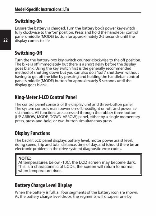
Switching-OnEnsure the battery is charged. Turn the battery box’s power key-switch fully clockwise to the “on” position. Press and hold the handlebar control panel’s middle (MODE) button for approximately 2-5 seconds until the display comes to life.
Switching-OffTurn the the battery-box key-switch counter-clockwise to the off position. The bike is off immediately but there is a short delay before the display goes blank. Using the key switch first is the generally recommended method of shutting down but you can also do a “soft” shutdown without having to get off the bike by pressing and holding the handlebar control panel’s middle (MODE) button for approximately 5 seconds until the display goes blank.
King-Meter J-LCD Control PanelThe control panel consists of the display unit and three-button panel. The system controls main power on-off, headlight on-off, and power as-sist modes. All functions are accessed through the rubber three-button (UP-ARROW, MODE, DOWN-ARROW) panel, either by a single momentary press, press-and-hold, or two-button simultaneous press.
Display FunctionsThe backlit LCD panel displays battery level, motor power assist level, riding speed, trip and total distance, time of day, and (should there be an electronic problem in the drive system) diagnostic error codes.
NOTE: At temperatures below -10C, the LCD screen may become dark. This is a characteristic of LCDs; the screen will return to normal when temperature rises.
Battery Charge Level DisplayWhen the battery is full, all four segments of the battery icon are shown. As the battery charge level drops, the segments will disapear one by

23
one. Should the battery reach a critically-low level, the icon will also blink slowly and the motor may be disabled; at this point the battery should be recharged as soon as possible.
The battery pack also has its own charge level display on the left rear, hidden under the carry handle. It is activated by pressing the red button of the display. The battery’s power switch must be on for the display to work.
Power Assist Level SelectMomentarily press the UP- or DOWN-ARROW buttons to change the output power of the motor relative to the speed of pedalling. Level 1 is minimum assist, 5 is maximum, and 0 disables power assist altogether. Assist level can be adjusted any time, including while in motion.
Headlight and Display Backlight On/OffSimultaneously press and hold the UP-ARROW and MODE buttons for 3-5 seconds to turn on the LCD backlight and bike headlight. The backlight brightness can be adjusted (see “Programming System Settings” below).
Riding Distance / Total Distance DisplayMomentarily press MODE to switch between showing trip distance (TRIP) or total distance (ODO). The trip distance is reset to zero whenever the bike is switched off.
Low-Speed CruisePress and hold DOWN-ARROW to engage a low-speed “cruising” mode that holds the bike at a steady 6-10Km/h on level ground.
WARNING!
Do not activate this mode unless riding; misuse may cause unintended acceleration.
ClockShows the time of day in 24hr format. To set the clock, see “Programming System Settings” below.
Model-Specific Instructions: LTn

24
Diagnostic Error Codes Displayln the event that a serious electronic control system fault is detected, the motor power will be cut and a numerical error code will be displayed on the LCD. While the code may be very helpful in troubleshooting the problem, it is not always a definitive pointer to the root cause. If basic checks associated with each code do not solve the problem, refer service to qualified technicians.
Error Code
21 Abnormal Current Possible causes: Shorted motor wiring, excessive vehicle weight, long uphills.
22 Throttle Fault Possible causes: Disconnected plugs, damaged wires between the throttle and controller, faulty throttle unit.
23 Motor Phase Defect Possible cause: damaged or disconnected motor power wire(s). Check that the motor-to-harness cable connector at the chainstay is fully en-gaged.
24 Motor Hall Sensor Defect Possible cause: damaged or disconnected motor hall sensor wire(s). Check that the motor-to-harness cable connector at the chainstay is fully engaged.
25 Brake Switch Circuit Possible cause: the brake switch input circuits are checked for shorts at power-on; operating either brake during power-on may cause this code to display but it will clear as soon as both levers are released.
Programming System SettingsTurn on the battery box key-switch and press and hold the MODE button for 1.5 seconds to switch-on the bike.
To enter programming mode, simultaneously press and hold both the UP-ARROW and DOWN-ARROW buttons for 2.5 seconds. Momentarily pressing MODE cycles through the programmable parameters, pressing the UP- or DOWN-ARROW buttons cycles though the available values for each parameter. Settings are accessed in the following order:
Clock: HH and MM, in 24hr format.
Model-Specific Instructions: LTn

25
Model-Specific Instructions: LTn
Maximum Speed Limit: this must be set no higher than 32km/h or 20mph (or other limit applicable to your jurisdiction) to remain within government regulations.
Units: Choose between reading speed and distance in Miles or Kilome-ters
Wheel Diameter: In inches, this setting affects the speedometer calibra-tion and speed limit function. It should be set to 26”.
LCD Backlight: Backlight brightness can be set to one of three levels.
To save all settings and exit at any point, press and hold the MODE button for 2.5 seconds until the dsplay returns to normal.
Shifting GearsGear shifting is like any bike with derailleurs and trigger shifters. You must be pedalling to make a proper shift.
CAUTION!Shifting when stopped can result in jamming or breakage of the chain.
The front three gears are selected with the left shifter; pushing the thumb lever forward shifts onto the bigger rings (higher gear, faster, harder to pedal) while pulling the index finger lever shifts to the smaller rings (lower gear, slower, easier).
The rear eight gears are selected with the right shifter; pushing the thumb lever forward shifts onto the bigger rings (lower gear, slower, easier) while pulling the index finger lever shifts to the smaller rings (higher gear, faster, harder to pedal).
BrakingBraking is like any conventional bicycle with similar equipment, but there is one added feature: when either brake lever is squeezed, the motor is shut off regardless of throttle or crank-sensor input.

26
Model-Specific Instructions: LTn
WARNING! It is important to frequently verify the proper operation of the brake switches, both for safety and to prevent undue stress on brakes and drive system.
Throttle GripJust like most motorcycles and scooters, a collar on the right-hand handlebar grip twists to control power delivery.
WARNING!Make sure that the throttle grip rotates smoothly and freely re-turns to the off position when released.
WARNING!Always make sure the power is off before trying to walk or move the bike by pushing or grabbing the handlebars since it is very easy to unintentionally twist the throttle grip.
Battery Pack FuseThe battery main fuse is located on the “front” end of the battery pack and is accessed with the pack removed from the bike. Remove the fuse cover (marked FUSE) by grasping with needle-nosed pliers. The fuse itself is removed in the same way. It is a standard 30A automotive-style “ATO” or “ATC” blade fuse.
CAUTION!Replace only with the same rating of fuse. Use of a higher-rated fuse can result in severe damage to protected equipment and possibly fire.

27
Model-Specific Instructions: LTf
LTf
In-Bike ChargingTurn off the power switch on the front-left side of the battery pack (based on the rider’s perspective, facing forward). Plug the charger’s AC power cord into the charger and then into a standard 120V AC power receptacle; the charger’s Charge State indicator LED should light up green. Plug the charger’s three-pin connector into the bike’s charging jack, located on the front-right side of battery box (there is no need to screw-on the plug’s ring - just make sure that the plug is all the way in the jack). After a few moments, assuming the battery actually needs charging, the Charge State led should turn red. Charging is complete when the Charge State led turns green.
Out of Bike ChargingTurn off the power switch on the front left side of the battery. Insert the bike’s ignition key into the battery box lock on the right-rear of the bat-tery box. Turn the key clockwise and hold it there while lifting the rear of the battery box upward using the handle. Charging is now performed exactly as described for in-bike.
Battery InstallationThe key does not need to be in the lock to install the battery. Angle the front of the battery slightly downward and lower it into the battery car-rier, followed by lowering the rear and pressing it firmly until it clicks into place. Lift up the battery handle to make sure the battery has latched securely.
Switching-OnEnsure the battery is charged. Turn on the power switch on the front-left side of the battery pack. Hold the body of the ignition key to the top of the display panel on the left handlebar grip - there is a magnet in the key that is sensed by the panel - until the display lights up. The red taillight will also illumiate whenever the bike is powered on.

28
Switching-OffTurn off the battery-box power switch. Using the battery switch first is the generally recommended method of shutting down but you can also do a “soft” shutdown without having to get off the bike by holding the key to the display panel on the left grip for approximately 5 seconds until the display goes dark.
Auto Shut-OffThe bike will switch itself off after approximately five minutes of inactivity.
Battery Charge Level DisplayWhen the battery is full, all four LEDs of the battery gauge will light. As the battery charge level drops, the LEDs will go out one by one. Should the battery reach a critically-low level the motor may be disabled; at this point the battery should be recharged as soon as possible.
The battery pack also has its own charge level display on its top. It is activated by pressing the red button of the display. The battery’s power switch must be on for the display to work.
Power Assist Level SelectThe output power of the motor, relative to the speed of pedalling, is adjustable in four levels. To increase the level, momentarily twist-and-hold the left grip collar upward for 1 second - the green LED will advance upward upon releasing the collar. To decrease the level, momentarily twist the collar downward for 1 second. The power-on default is always the lowest level. The setting is indicated by which of the four LEDs is lit. Assist level can be adjusted any time, including while in motion.
Headlight On/OffThe headlight is powered by its own (non-rechargeable) battery. Press the button switch on the top of the light housing to turn it on or off.
Model-Specific Instructions: LTf

29
Model-Specific Instructions: LTf
Shifting GearsThe three-speed internally-geared rear hub is controlled by twisting the right-hand grip collar up or down, with the selected gear displayed in the shifter window. 1 is the lowest (easisest, slowest) gear. You can shift gears both when moving or stopped.
Thumb ThrottlePower-on-demand is controlled by the thumb throttle near the right hand grip. Push the lever downward to accellerate.
WARNING!Always make sure that the throttle lever moves smoothly and freely returns to the off position when released.
WARNING!Always make sure the power is off before trying to walk or move the bike by pushing or grabbing the handlebars since it is very easy to unintentionally activate the throttle.
Battery Pack FuseThe battery main fuse is located on the bottom “forward” end of the bat-tery pack and is accessed with the pack removed from the bike. Unscrew the fuse holder cover using a Philips #2 screwdriver and withdraw the fuse. It is a standard 6.3x32mm (1/4”x1 1/4”) tubular glass or ceramic bodied “cartridge” style fuse, quick-acting, rated at 30A.
CAUTION!Replace only with the same rating of fuse. Use of a higher-rated fuse can result in severe damage to protected equipment and possibly fire.

30
FoldingTurn off power switch.
Loosen the seat adjustment quick-release lever and lower seat to bottom of travel.
Loosen handlebar stem height adjustment quick-release lever and lower handlebars to bottom of travel.
Unlock the handlebar stem hinge (pull lock lever out and downward against the spring presure) and flip the stem and bars downward.
Flip the safety cover of the frame centre hinge lock upward to clear the lock lever and pull lever away from top tube to release. Fold frame.
Frame Hinge Lock AdjustmentThe tension of the frame hinge lock can be adjusted to remove any play in the joint. Use a 5mm allen wrench to tighten (clockwise) the adjusting bolt (visible when the lever is open) until the the hinge is play-free but does not require excessive force to lock.
Model-Specific Instructions: LTf

31
Model-Specific Instructions: CTr
CTr
ChargingTurn off the power key-switch on the front left side of the top tube (right or left are based on rider’s perspective, facing forward). Plug the charger’s AC power cord into the charger and then into a standard 120V AC power receptacle; the charger’s Charge State indicator LED should light up green. Plug the charger’s coaxial output connector into the bike’s charg-ing jack located near the power key-switch. After a few moments (assum-ing the battery actually needs charging), the Charge State led should turn red. Charging is complete when the Charge State led turns green.
Switching-OnEnsure the battery is charged. Turn the key-switch on the front-right side of the top-tube clockwise to the “on” position. The control panel battery and assist level LEDs will light.
Switching-OffTurn the the key-switch counter-clockwise to the off position.
Battery Charge Level DisplayWhen the battery is full, all four LEDs of the battery gauge will light. As the battery charge level drops, the LEDs will go out one by one. Should the battery reach a critically-low level the motor may be disabled; at this point the battery should be recharged as soon as possible.
Power Assist Level SelectThe output power of the motor, relative to the speed of pedalling, is adjustable in three levels. The power-on default is “low”. To increase the level, momentarily press the “+” button. To decrease the level, momen-tarily press the “-” button. The setting is indicated by which of the three LEDs is lit; when no LED is lit, power assist is disabled. Assist level can be adjusted any time, including while in motion.

32
Headlight On/OffThe headlight is powered by the bicycle’s battery. Press the headlight icon button on the control panel to turn the headlight on or off.
Shifting GearsGear shifting is like any bike with a derailleur and trigger shifter. You must be pedalling to make a proper shift.
CAUTION!Shifting when stopped can result in jamming or breakage of the chain.
The eight rear gears are selected by the right-hand shifter. Push forward on the thumb lever to shift “down” to the larger cogs (lower gears, easier, slower) and press the button to shift “up”, one gear per click.
Throttle GripJust like most motorcycles and scooters, a collar on the right-hand handlebar grip twists to control power delivery.
WARNING!Make sure that the throttle grip rotates smoothly and freely re-turns to the off position when released.
WARNING!Always make sure the power is off before trying to walk or move the bike by pushing or grabbing the handlebars since it is very easy to unintentionally twist the throttle grip.
Model-Specific Instructions: CTr

33
About the Electric Drive Train
How it WorksCompared to an internal combustion engine, your MOTORINO Bicycle’s drive system is elegantly simple.
Electric power stored in the battery pack is supplied to the motor control-ler.
The controller converts the battery’s direct-current to three-phase alternating-current and sends it to the direct-drive brush-less motor built into either the front or the rear wheel hub. There is no chain between the motor and the road - it is there for the human-powered drivetrain only.
The controller receives rider input from the throttle grip and/or crank rotation sensor to determine how much power to send to the motor; the power developed depends on the amplitude, frequency, and shape of the AC waveform the controller produces.
When the controller receives a signal from the brake lever switches that the brakes have been applied it cuts power to the motor.
E-Riding Tips Accelerate gradually, ride smoothly.
Avoid deep battery discharge.
Charge as soon as possible after each ride.

34
Battery Information, Care, and FeedingAll MOTORINO™ Electric Bicycles use lithium-chemistry batteries, combin-ing high energy storage capacity with light weight, small size, and low self-discharge.
Caring for your Lithium Battery PackLithium batteries are maintenance-free and do not quickly self discharge or degrade in storage. However, keeping these points in mind will help you get the most from them:
1. They do not like over-charging or under-voltage.
No batteries really do, of course, but lithium-chemistry cells are particu-larly picky. The batteries in your MOTORINO™ have internal protection circuitry that disconnects the cells when at risk of being over or under charged to the point of serious damage. That said, it is still very impor-tant that the battery be recharged promptly if the low voltage cut-out is tripped. This is because “self-discharge”, although very slow compared to other types of batteries, can still take the cells into dangerously low-voltage territory.
2. They prefer not to be deeply discharged
Similar to lead-acid cells but to a much lesser degree, a lithium battery pack will give more mileage over its lifetime if you minimize the depth of discharge. The trade-offs are hard to quantify in real world use, so just do what you can.
NOTE: There is no such thing as a “memory effect” in relation to lithium batteries; the “advice” to fully discharge before recharging only ever applied to old-tech Nickel Cadmium batteries.
Battery LifespanReplacing the battery pack is an inevitable part of riding an EV. Even when you do everything right, the natural order of things is for the capac-ity of batteries to decrease ever so slightly with every charging cycle, and the deeper the discharge, the proportionally greater the loss. They also
Battery Information, Care, and Feeding

35
age chemically when sitting on the shelf, but proper storage will make that far less of a factor than actual use.
“How long will my batteries last?” is almost impossible to answer since it will be highly dependent on how far you ride, both in-total and between charges, and what your needs are. There is no set schedule for replace-ment; it falls to the owner to decide when the range of the bike can no longer meet their needs.
A Word on Replacement BatteriesUnlike many e-scooters, battery packs for electric bicycles are very model-specific in both physical and electrical characteristics. Correct replace-ments may be purchased from your MOTORINO™ dealer.
Battery Disposal and RecyclingWhen the battery pack is no longer viable, it should be removed from the bike and delivered to a recycling facility. Laws prohibit disposal of any large lithium batteries in everyday trash. Please contact your local solid waste or recycling authority for recycling information in your area.
Battery Information, Care, and Feeding

36
MaintenanceNobody can keep an eye on the condition of your MOTORINO™ Elelctric Bicycle like you can. It is up to you keep it maintained and obtain ser-vicing as required. Being fully familiar with your MOTORINO™’s regular operation will also help you spot potential trouble before it becomes a breakdown.
WARNING!Failure to maintain your MOTORINO™ can result in unsafe opera-tion, regulatory non-compliance, damage to components, and possible denial of warranty coverage.
Fortunately, unlike an internal-combustion vehicle, the electric drive system requires very little maintenance beyond charging the battery and regular inspections of the exposed cabling.
The rest of the maintenance and adjustment items are the same as on conventional bicycles. And just as with conventional bicycles, some items are very simple but others require special tools and a fair bit of skill and experience to do correctly. If you have any doubts about your own abili-ties, refer servicing to your MOTORINO™ dealer or a competent bicycle mechanic. Bear in mind that in-warranty repairs must be referred to your MOTORINO™ dealer.
Service InformationRather than attempt to explain how to maintain a bicycle in this limited space, the focus will be on a few general yet critical areas. The Internet offers a wealth of articles and videos on every aspect of bicycle main-tenance and repair, but two very reliable sources to start you off are bicycling.com and sheldonbrown.com
Detailed manufacturers’ technical service information for the various components used on MOTORINO™ electric bicycles has been compiled and listed by model in the Support section at motorino.ca
Maintenance
37
Periodic Maintenance ScheduleMaintenance time periods are approximates based on semi-daily use in moderate weather. Heavy use, winter weather or otherwise harsh condi-tions may necessitate shorter intervals between checks and service. Refer to the applicable section of this user guide or the specific component manufacturers’ technical documentation for detailed service procedures.
Daily/Every RidePre-Ride Checks (page 12).
WeeklyClosely inspect tires for tread wear, foreign objects, and damage.
Check that wheels spin freely, bearings feel smooth, and rims run true.
MonthlyClosely inspect wheels for damage and loose spokes.
Lubricate chain and cables.
Inspect brake pads and rims/rotors for excessive wear.
Check all axle nuts/skewers and brake hardware.
Inspect wires and cables, especially on front fork and around other mov-ing parts. Check cable connectors.
Check steering column (aka “headset” ) for bearing play.
Check crank bolts.
Maintenance

38
Maintenance ProceduresWARNING!The instructions here are intended for people with sufficient me-chanical aptitude and experience to work on motor vehicles and bicycles. If in doubt about your abilities to carry out any of these procedures, refer inspection and servicing to your MOTORINO™ dealer.
Cleaning and Lubricating the ChainThere are many bicycle-specific chain lubricants on the market but any non-detergent machine oil is likely suitable; the trade-off is cleanliness vs duration of effectiveness with the thinner lubricants requiring more frequent application but attracting less dirt. That said, WD-40 is not at all suitable as a lubricant, although it can be used as a cleaning solvent.
A drop of oil on each chain link roller/pin, between the side plates, is all that is needed. Remove excess oil with a rag but always leave a slight film to prevent rust. A spray-on chain lube can also be used as long as care is taken to keep oil or grease off of the brake parts (including wheel rims) and tires.
To clean the chain without removing it from the bike, you can use a solvent-soaked rag. Care must be taken to avoid getting solvent into the bottom bracket or motor bearings, etc.
Checking Brake Pads and Rims/Rotors for WearYour brakes are the most critical of safety components and should be checked regularly for security of fasteners and wear. Worn-through brake pads will very quickly ruin the brake rotor or wheel rim, compounding the costs and increasing downtime, so it is a false economy to ever delay replacement.
Rim-brake pads should be replaced before the friction material reaches the “wear limit” line usually cast into the top of the pad. This line almost always coincides with the bottom of the grooves, or “tread”, of the pad.
Disc brake pads can usually be checked in-place with the help of a bright flashlight by sighting along the surface of the brake rotor. Be sure not to confuse the pad backing plates with pad friction material.
Maintenance

39
Refer to the brake manufacturer’s technical documentation for specific measurements and replacement procedures.
Rim and rotor braking surfaces should be free of deep grooves. Check for signs of cracking. The minimum allowable disc brake rotor thickness is specified by the manufacturer but sometimes also marked on the rotor.
Checking Brake AdjustmentGenerally, the brake levers should move about half way toward the grip with moderate force. They should no more than just begin to touch the grip with full “panic” force applied.
There is often a compromise between solid brake action and risk of drag. With rim brakes, rim trueness plays a big part in determining the mini-mum clearance (and there fore “slack”) needed to prevent rubbing. Disc brakes are sensitive to rotor warp and caliper alignment. Excessive friction in pivot points or cables can lead to dragging or inability to attain correct action.
Please refer to the technical documents for your model and specific com-ponents for definitive servicing and adjustment information.
Checking Wheel Bearing PlayIn normal use, the sealed ball bearings in motor hubs do not require adjsutment or lubrication and only need to be checked for abnormal wear or damage. Non-powered hubs may have adjustable “cup-and-cone” bearings and these may need adjustment, cleaning and repacking, or complete bearing ball repalacement from time to time depending on their design and operating conditions.
To check, grab the top of the wheel and try to rock it perpendicular to the axle axis. Play will be felt as a looseness between two hard stops. Only the slightest perception of play is acceptable.
Once you have ascertained that any play is not because of loose axle nuts, refer motor bearing replacement to your MOTORINO™ dealer.
Checking for Steering Bearing (Headset) PlayThe steering column runs on upper and lower ball bearings. Depending on the model, they may be adjustable or fully sealed. In normal use they
Maintenance

40
do not require servicing other than an occasional adjustment. Problems usually only arise due to hard impacts.
To check for play, stand over the bike and squeeze the front wheel’s brake lever so that the wheel is locked. Rock forward and backward slightly as if to roll the bike. Play will be felt as a looseness between two hard stops and should be distinct from a bit of natural flexing of parts.
Refer bearing adjustment or replacement to your MOTORINO™ dealer.
TiresYour tires are the only thing between you, your MOTORINO™, and the hard, unforgiving pavement. All going, turning, and stopping happens through your tires. Take good care of them.
Tire PressureTire pressure is one of the most critical factors determining the effective range and efficiency of your MOTORINO™. We recommend maintaining the maximum pressure indicated on the sidewalls of your tires for maxi-mum efficiency and handling safety.
WARNING!In addition to poor range, high pedalling effort, and bad handling performance, low tire pressures can increase the load on the controller and motor causing overheating and possible failure. Riding with the tires at very low pressures can also result in the tire bead coming unseated from the rim, leading to a sudden flat, rim, tube and tire damage, and a possible crash.
CAUTION!Always use a suitable, accurate tire pressure gauge when filling tires from any air source.
Checking Tires for Condition and Foreign ObjectsRegularly inspect your tires for signs of damage or wear such as penetra-tion by nails and other sharp objects, objects stuck in tread grooves, pinched or bulged sidewalls, cracking, delamination, and flat-spotted or worn-through tread.
Maintenance
41
Tire Replacement
WARNING!Replace only with a correctly-sized tire and/or tube.
Choose a high-quality tire that can handle the extra weight of an elec-tric bike. Higher-pressure tires with smooth tread generally give better efficiency, making for easier pedalling and longer electric range, but may rid a bit harder as well. Tires specifically labeled as suitable for electric bicycles are a safe bet.
If replacing an inner-tube, be sure to purchase one of the correct size for the tire and with the correct style (Schrader or Presta) and length of valve stem (to suit deep or shallow rim profiles).
Dealing with a Flat Tire
CAUTION!Special care must be taken when removing the powered wheel to avoid damage to the cabling or connector. Extra attention should be paid to where the motor cable exits the axle.
Flats and slow leaks can come from damage to the tube/tire itself or a loose valve core.
A tube patch kit can often allow a quick roadside repair to most punc-tures, so long as you have a way to reinflate the tube. It is often possible to apply a patch without removing the wheel from the bike which is an important advantage when dealing with a flat on the powered wheel.
Preemptive Tire Sealant As a preemptive measure, your MOTORINO™ dealer can install a product which is capable of nearly immediately sealing a puncture, often without you even noticing. Since it remains a liquid until it’s forced out of a leak, it also acts as a kind of dynamic balancer, potentially making your bike run even smoother.
Maintenance

42
MOTORINO™ LoveYour MOTORINO™ will run even better when it is clean and shiny. :-)
WashingUse only a soft cloth, water, and a mild soap suitable for automotive fin-ishes. Gently rain water down onto the bike, being especially careful not to force it into areas it does not normally go. Wash from top to bottom to avoid scratching the more visible parts of the frame grit from the lower areas. Rinse off any soap residue before it can dry. Dry the finish with a scratch-free, soft, perfectly clean chamois cloth.
Rinsing the bike immediately after riding in on muddy or salted roads is strongly recommended.
CAUTION!DO NOT use a pressure washer or other concentrated jet of wa-ter. There is considerable risk of forcing water past seals and into bearings, shocks, the motor, electrical connectors, controls, light fixtures, and even damaging the finish.
WaxingWax will help protect painted and chromed surfaces and make it easier to remove dirt and road tar. Only use products suitable for fine automo-tive finishes. and keep them off of the rim braking surfaces and/or brake rotors.
Protecting Metal SurfacesExposed chromed and other metal surfaces are subject to rust and corro-sion, especially when used on salted streets. Regular use of a protective wax or spray product is recommended.
WARNING!DO NOT allow wax, oil, grease, or other contaminants to remain on brake parts or tires. Use alcohol to clean the rim or disc brake friction surfaces and pads if necessary. Use dish soap and warm water to clean tires.
MOTORINO™ Love

43
StorageAll vehicles seem to do better when in regular use; components have a chance to warm up and air out, batteries stay charged, and tires and other rubber parts are kept pliable.
CAUTION!The battery is the most perishable component on the bike; it must be stored at least 70% charged to avoid degradation or serious damage.
Short-Term Storage (Under 1 Month)As long as the battery is charged to at least 70% and the hardware power switch is off (or the battery remocved from the bike), there is no worry in short term storage. Keep dry.
Long-Term StorageFully charge your battery and turn off the hardware power switch. Bring indoors if possible.
At least once every six months, charge the battery.
Keep tires fully inflated.
Beware of high humidity; it can cause corrosion of electrical connections and possible internal rusting of the motor magnets. Finding a low-humid-ity well-ventilated indoor location should be a priority. Beware of using a cover when over moist ground since that can act as a moisture trap and be worse than no cover at all.
Storage

44
TroubleshootingThe following information may help you get going in the case of a simple problem but is not a repair guide; always refer repairs to qualified person-nel. The causes/solutions are presented with the most-likely ones first.
Nothing happens when the power is turned ON; the motor does not activate at all, no lights appear on the dash, and there’s no reading on the battery display.
Battery pack circuit breaker or fuse has blown or is loose.1.
Check removable battery seating and connections.2.
The power key switch may not be fully in the ON position. Make sure 3. you are using the correct key. Wiggle the key in the switch while watching for any display response. If wiggling works, this could indicate a problem requiring replacement of the ignition switch. Refer repair to your MOTORINO™ dealer.
Bad connection to battery pack, controller, or in wiring harness. Refer 4. repair to your MOTORINO™ dealer.
The motor does not run at all, however control panel comes on as normal.
Check that the brake levers are not stuck in the on position. Push the 1. brake levers forward (away from the grip) to see if one might be stick-ing.
If the battery gauge drops then recovers quickly when the throttle is 2. activated, the battery may be too depleted and the low-voltage cut-out is being triggered. Charge the bike.
Make sure the throttle body is secure and not turning with the grip3.
The bike has limited range.
Tire pressures may be low. Check and inflate1.
Bike is over-loaded. Reduce cargo weight; remove unnecessary items. 2.
Review charging procedures, make sure a full charge is being given3.
Troubleshooting

45
Battery is aged or failing.4.
The bike runs fine on flat ground but dies on hills. The motor pulses on and off.
Low voltage cut-out is being triggered. Charge batteries.1.
See solutions for limited range, above.2.
The bike feels slow.
See limited range solutions above.1.
Make sure the throttle body is secure and not turning with the grip, 2. and that the grip’s range of motion is normal.
A brake is weak and/or the brake lever touches the grip.
Brake cable needs adjustment / hydraulic fluid level low or needs 1. bleeding.
Contamination (oil, grease, wax etc.) on brake rotor and/or pads. 2. Clean with dish detergent and/or alcohol.
Brake pads worn or out of alignment.3.
Brakes are noisy.
1. Metal-on-metal contact. Check brake pads for wear.
2. Non-wear related brake squeal. This is mainly just an annoyance and is quite common. If the pads are OK, clean all braking surfaces (rim sides or rotor) with alcohol and/or dish detergent.
The speedometer readout is always zero or is fluctuating wildly.
1. Sensor misaligned or too far from wheel magnet; magnet missing. When aligning a sensor with the magnet, pay attention to any markings on the sensor to find the precise alignment point.
2. Damaged or disconnected sensor wiring.
Troubleshooting

46
Specifications
SpecificationsOur policy is to incorporate improvements in design and features as they become available. Therefore, specifications are subject to change without notice. Visit www.motorino.ca for information on your specific model.

47
WarrantyTo activate your warranty, visit:
www.motorino.ca/warranty
or fill out the warranty form at your Greenwit-authorized MOTORINO™ retailer.
Limited Warranty Greenwit Technologies Inc. (“Greenwit”) warrants to the original retail purchaser (“you”) that the Greenwit MOTORINO™-brand electric bicycle for which this warranty has been issued is free from defects in materials and workmanship as follows:
Frame: 24 months (excluding kick stands) Electric Motor: 12 months Controller and electric circuits: 12 months Chargers: 6 months Lithium Batteries: 24 months
This warranty is not transferable to a subsequent purchaser. Greenwit’s dealers’ sole obligation under this warranty is to repair or replace the product, at their option. Greenwit’s dealer must be notified in writing of any claim under this warranty within 10 days of the discovery of any fault or defect.
Immediately report any abnormal product behavior to Greenwit or a Greenwit-authorized dealer.
Warranty LimitationsThe duration of any implied warranty or condition, of merchantability for a particular purpose, or otherwise, on this product shall be limited to the duration of the warranty expressed above. In no event shall Greenwit or Greenwit dealers be liable for any loss, inconvenience or damage, wheth-er direct, incidental, consequential or otherwise, resulting from a breach of any expressed or implied warranty condition, of merchantability for a particular purpose, or otherwise with respect to this product, except as set forth herein. This warranty gives you specific legal rights, in addition to other consumer rights bestowed by your province or state.
This warranty will be interpreted pursuant to the laws of Canada and USA. The original English language version of this warranty supersedes all
Consumer Information

48
Consumer Information
translations and Greenwit is not responsible for any errors in translation of this warranty or any product literature.
This warranty is not intended to confer any additional legal, jurisdictional or warranty rights to you other that those set forth herein or required by law. If any portion of this warranty is held to be invalid or unenforceable for any reason, such finding will not invalidate any other provision. For products purchased outside Canada please contact Greenwit’s authorized distributor in that country.
Under no circumstances is Greenwit liable for any consequences of the assembly, inspection, or service work of their dealers.
Warranty Frequently Asked QuestionsQ. What costs are my responsibility during the warranty period? A. The customer is responsible for the cost of all normal maintenance services and parts, non-warranty repairs, accident and crash damage, and items normally considered as consumables such as, but not limited to, tires, brake pads, brake fluid, and lubricants.
Q. Does the warranty cover costs of towing or transport due to a failure? A. No. The warranty is limited to the repair of the machine itself.
Q. What responsibility does my dealer have under this warranty? A. Each authorized MOTORINO™ dealer is expected to set up every new machine before sale; explain operation, maintenance, and warranty at time of sale and upon request afterward; and is responsible for their setup, service, and warranty repair work.
Q. Can I transfer the warranty to the new owner if I sell my MOTORI-NO™? A. No. The warranty extends only to the original purchaser.

49
Legal Classification and Regulatory ComplianceCAUTION!It is entirely the rider’s responsibility to know, understand, and obey all applicable vehicle and traffic laws wherever they may go. It is the rider’s responsibility to comply with all applicable regulations. Un-authorized modifications made to this bike can result in the vehicle becoming unsafe and/or illegal to use.
NOTE: Neither Greenwit Technologies Inc. nor its retailers are responsible for the consequences of failure to comply with any applicable laws and regulations.
Your MOTORINO™ bike complies with and is classified as a Power Assisted Bicycle as defined under section 2(1) of the Canadian Motor Vehicle Safety Regulation Act (c.1038). It is also compliant with US Public Law 107-319 for importation and use in states where it is in force. In all cases, pedals must be attached and operational to maintain compliance.
Local and regional governments may have additional helmet laws, minimum-age requirements, passenger and cargo limitations, or other restrictions beyond those covered by federal regulation.
Some Canadian and US jurisdictions may classify your MOTORINO™ as a Limited Speed Motorcycle or Moped. Check with the applicable motor vehicle authority and/or insurance company for information specific to your area.
Consumer Information

50
Owner’s Information and Notes
Owner’s Name:
Bike Model:
Bike Colour:
Frame Serial Number:
Motor Serial Number:
Battery Type:


Rev. 2013-10-001 DRAFT 002
ww
w.m
otor
ino.
ca