
ELECTIVE –II - TCP/IP(18MIT35E)
110
ELECTIVE –II - TCP/IP(18MIT35E) UNIT-I: A Brief History: Arpanet – (TCP/IP) – Milnet – Csnet – Nsfnet – Ansnet – Protocols and Standards – Standards Organisations – TCP/IP Protocol Suite – Addressing – Connection Devices. Introduction – Classful addressing – Subnetting – Supernetting – Classless addressing. Text Book : 1.Behrouz A. Forouzan, “TCP/IP Protocol Suite”, Tata Mcgraw-Hill Publishing Company, Second edition. Reference Books: 1.W. Richard Stevens, “TCP/IP Illustrated: The Protocols”, Vol.1, Pearson Education. 2. Comer , ” Inter networking with TCP/IP : Principles ,protocols & Architecture”,Vol.1,fourth Edition, Pearson Education. Prepared by Dr.M.Soranamageswari 1
Transcript of ELECTIVE –II - TCP/IP(18MIT35E)
ELECTIVE –II - TCP/IP(18MIT35E)UNIT-I: A Brief History: Arpanet – (TCP/IP) – Milnet – Csnet –Nsfnet – Ansnet – Protocols and Standards – Standards Organisations – TCP/IP Protocol Suite – Addressing – Connection Devices. Introduction – Classful addressing – Subnetting –Supernetting – Classless addressing. Text Book :1.Behrouz A. Forouzan, “TCP/IP Protocol Suite”, Tata Mcgraw-HillPublishing Company, Second edition.Reference Books:1.W. Richard Stevens, “TCP/IP Illustrated: The Protocols”, Vol.1, Pearson Education. 2. Comer , ” Inter networking with TCP/IP : Principles ,protocols & Architecture”,Vol.1,fourth Edition, Pearson Education.
Prepared byDr.M.Soranamageswari
1
1.1 A Brief History of networks
• A network is a group of connected, communicating devicessuch as computers and printers.
• An internet is two or more networks that can communicatewith each other. The most notable internet is called the Internet, composed of hundreds of thousands of interconnectednetworks.
• Private individuals as well as various organizations such asgovernment agencies, schools, research facilities, corporations,and libraries in more than 100 countries use the Internet.•Millions of people are used internet.
2

1.1.1 ARPANET :
• In the mid-1960s, mainframe computers in research organizations were stand-alone devices.
• Computers from different manufacturers were unable to communicate with one another.
• The Advanced Research Projects Agency (ARPA) in the Department of Defense (DOD) was interested in finding a way to connect computers together.
3
Cont…
• In 1967, at an Association for Computing Machinery (ACM) meeting, ARPA presented its ideas for ARPANET, a small network of connected computers.
• The idea was that each host computer (not necessarily from the same manufacturer) would be attached to a specialized computer, called an interface message processor (IMP).
• The IMPs, in turn, would be connected to each other. Each IMP had to be able to communicate with other IMPs as well as with its own attached host.
4

1.1.2 Transmission Control Protocol/Internetworking Protocol (TCP/IP)
• This was a new version of NCP.
• Transmission control protocol (TCP) included concepts such as encapsulation, the datagram, and the functions of a gateway.
• A radical idea was the transfer of responsibility for error correction from the IMP to the host machine.
• In October 1977, an internet consisting of three different networks (ARPANET, packet radio, and packet satellite) was successfully demonstrated.
•Communication between networks was now possible. 5
TCP has two protocols:
1. Transmission Control Protocol (TCP) and2. Internet Protocol (IP).
• IP would handle datagram routing while TCP would be responsible for higher level functions such as segmentation, reassembly, and error detection. • The new combination became known as TCP/IP.• In 1981, UC Berkeley modified the UNIX operating system to include the TCP/IP.• In 1983, authorities abolished the original ARPANET protocols, and TCP/IP became the official protocol for the ARPANET. • Those who wanted to use the Internet to access a computer on a different network had to be running TCP/IP. 6
1.1. 3 MILNET
• In 1983, ARPANET split into two networks: MILNET for military users and ARPANET for nonmilitary users.
1.1.4 CSNET(Computer Science Network)
• Another milestone in Internet history was the creation of CSNET in 1981. • CSNET was a network sponsored by the National Science Foundation (NSF). • The network was conceived by universities that were ineligible to join ARPANET due to an absence of defense ties to DARPA. • CSNET was a less expensive network, there were no redundant links and the transmission rate was slower.
7
1.1. 5 NSFNET
• With the success of CSNET, the NSF, in 1986, sponsored NSFNET, a backbone that connected five supercomputer centers located throughout the United States. • Community networks were allowed access to this backbone, a T-1 line with a 1.544-Mbps data rate, thus providing connectivity throughout the United States.
• In 1990, ARPANET was officially retired and replaced by NSFNET.
• In 1995, NSFNET reverted back to its original concept of a research network.
8
1.1. 6 ANSNET
• In 1991, the U.S. government decided that NSFNET was notcapable of supporting the rapidly increasing Internet traffic.
• Three companies, IBM, Merit, and MCI(microwavecommunication inc), filled the void by forming a nonprofitorganization called Advanced Network and Services (ANS) tobuild a new, high-speed Internet backbone called ANSNET.
9
1.2 Protocols and StandardsProtocols• Communication between two people or two devices needs tofollow some protocol.• A protocol is a set of rules that governs communication.• For example, in a face-to-face communication between twopersons, there is a set of implicit rules in each culture that definehow two persons should start the communication, how tocontinue the communication, and how to end the communication.• In computer networks, communication occurs between entitiesin different systems.• An entity is anything capable of sending or receivinginformation. However, two entities cannot simply send bitstreams to each other and expect to be understood.
10

The key elements of a protocol are syntax, semantics, and timing.
• Syntax: Syntax refers to the structure or format of the data,meaning the order in which they are presented.
• Semantics: Semantics refers to the meaning of each section ofbits. How is a particular pattern to be interpreted, and what actionis to be taken based on that interpretation?
• Timing : Timing refers to two characteristics : when datashould be sent and how fast it can be sent.
11
Standards:
• Standards are essential in creating and maintaining an open andcompetitive market for equipment manufacturers and also inguaranteeing national and international interoperabilityof data and telecommunications technology and processes.
• They provide guidelines to manufacturers, vendors, governmentagencies, and other service.
• The service providers ensure the kind of interconnectivity andalso necessary to marketplace in internationalcommunications.
12

Data communication standards fall into two categories: 1. de facto (meaning “by fact” or “by convention”) 2. de jure (meaning “by law” or “by regulation”).
1. De facto: • Standards that have not been approved by an organized body but have been adopted as standards through widespread use are de facto standards. • De facto standards are MS Office and various DVD (Digital Versatile Disc)standards.
2. De jure: • De jure standards are those that have been legislated by an officially recognized body.
13

1.3 Standards organization
Standards are developed through the cooperation ofstandards creation committees, forums, and governmentregulatory agencies.
Standards Creation Committees
• While many organizations are dedicated to theestablishment of standards, data communications
14

1.International Standards Organization (ISO):
• The International Standards Organization (ISO), alsoreferred to as the International Organization forStandardization) is a multinational body.
• The membership is drawn mainly from the standardscreation committees of various governments throughout theworld.
• It is Created in 1947, the ISO is an entirely voluntaryorganization dedicated to worldwide agreement oninternational standards.
15

2. International Telecommunications Union–Telecommunications Standards Sector (ITU-T):
• The early 1970s, a number of countries were defining nationalstandards for telecommunications, but there was still littleinternational compatibility.
• The International Telecommunications Union (ITU)committee is Consultative Committee for InternationalTelegraphy and Telephony (CCITT).
• The CCITT committee was devoted to the research andestablishment of standards for telecommunications in generaland phone and data systems.
16

3.American National Standards Institute (ANSI)
•The American National Standards Institute (ANSI) is a completely private, nonprofit corporation .
•It is not affiliated with the U.S. federal government.
•ANSI activities are undertaken with the welfare of the United States and its citizens to occupying primary importance.
•ANSI members include professional societies, industry associations, governmental and regulatory bodies, and consumer groups.
17
4. Institute of Electrical and Electronics Engineers (IEEE):
• The Institute of Electrical and Electronics Engineers (IEEE) is the largest professional engineering society in the world. International.
• It aims to advance theory, creativity, and product quality in the fields of electrical engineering, electronics, and radio.
• The IEEE to development and adoption of international standards for computing and communication.
18
5. Electronic Industries Association (EIA) :
• The Electronic Industries Association (EIA) is anonprofit organization.• The promotion of electronics manufacturing concerns todevoted.• Its activities include public awareness education andlobbying efforts in addition to standards development.• In the field of information technology, the EIA hasmade significant contributions by defining thephysical connection interfaces .• It also connected to electronic signaling specificationsfor data communications.
19

6. World Wide Web Consortium (W3C) :
•Tim Berners-Lee founded this consortium at MassachusettsInstitute of Technology Laboratory for Computer Science.•It was founded to provide computability in industry for newstandards.•W3C has created regional offices around the world.
7. Open Mobile Alliance (OMA) :
• The standards organisation OMA was created to differentforums in computer networking and wireless technology.• The umbrella of one single authority. Its mission is toprovide unified standards for application protocols.
20
1.4 TCP/ IP Protocol Suite
The TCP/IP protocol suite became the dominant commercial architecture because it was used and tested extensively in the Internet.
TCP/IP as a protocol suite objectives:
❑ To discuss the idea of multiple layering in data communication and networking and the interrelationship between layers.❑ To discuss the OSI model and its layer architecture and to show the interface between the layers.
21
❑ To briefly discuss the functions of each layer in theOSI model.
❑ To introduce the TCP/IP protocol suite and compareits layers with the ones in the OSI model.
❑ To show the functionality of each layer in theTCP/IP protocol with some examples.
❑ To discuss the addressing mechanism used in somelayers of the TCP/IP protocol suite for the delivery of amessage from the source to the destination.
22
1.4 TCP/IP protocol suite
The TCP/IP protocol suite was developed prior to the OSImodel.
The original TCP/IP protocol suite was defined as foursoftware layers built upon the hardware.
Today, TCP/IP is thought of as a five-layer model with thelayers named similarly to the ones in the OSI model.
23

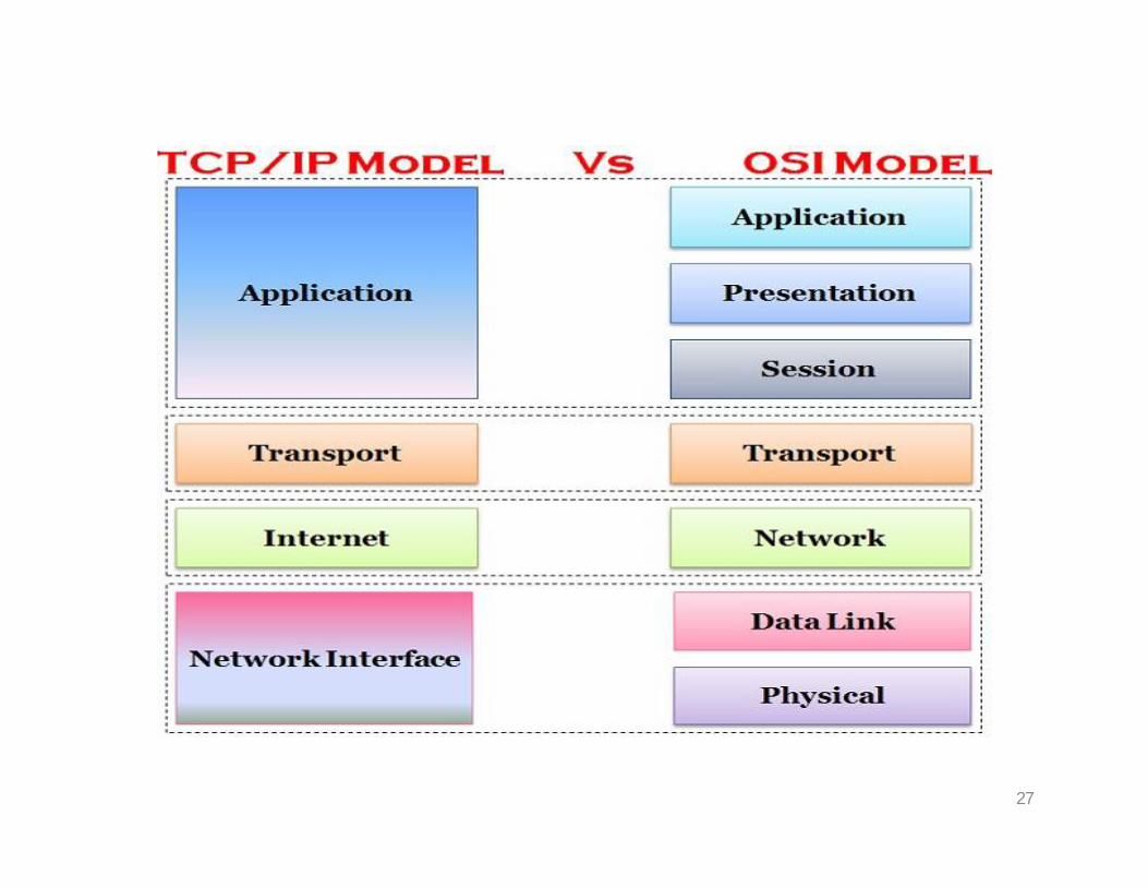
1.4.1 Comparison between OSI and TCP/IP Protocol Suite:
When we compare the two models, we find that two layers,session and presentation, are missing from the TCP/IPprotocol suite.
The application layer in the suite is considered to be thecombination of three layers in the OSI model.
TCP/IP has more than one transport-layer protocol. Someof the functionalities of the session layer are available in someof the transport layer protocols. Second, the application layer is not only one piece ofsoftware. Many applications can be developed at this layer.
24
TCP/IP is a hierarchical protocol made up of interactivemodules, each of which provides a specific functionality,but the modules are not necessarily interdependent.
Whereas the OSI model specifies which functions belongto each of its layers, the layers of the TCP/IP protocol suitecontain relatively independent protocols that can be mixedand matched, depending on the needs of the system.
The term hierarchical means that each upper levelprotocol is supported by one or more lower level protocols.
25
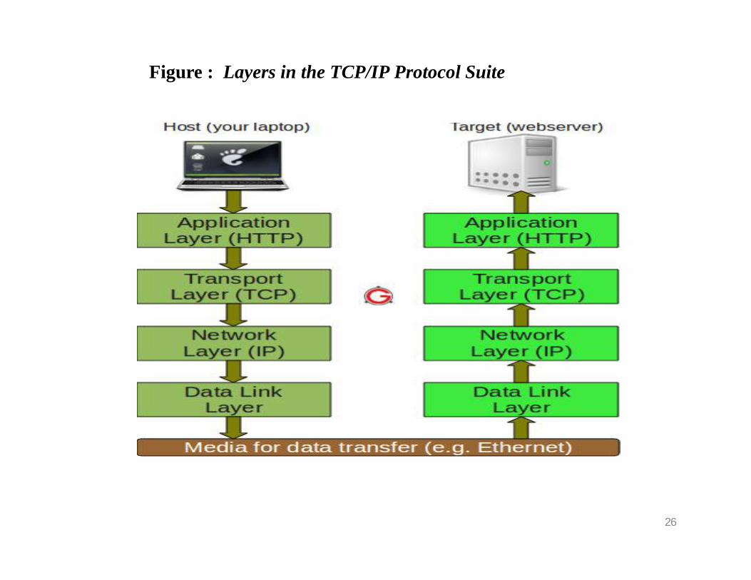
Figure : Layers in the TCP/IP Protocol Suite
26
27
1.4.2 Layers in the TCP/IP Protocol Suite
In this section, we briefly discuss the purpose of each layer in the TCP/IP protocol suite
When we study the purpose of each layer, it is easier to think of a private internet, instead of the global Internet. We assume that we want to use the TCP/IP suite in a small, private internet.
Such an internet is made up of several small networks, which we call links.
A link is a network that allows a set of computers to communicate with each other.
28
Cont…
If several computers belonging to a private company are connected via a satellite channel, the connection is a link. A link, can be a LAN (local area network) serving a small area or a WAN (wide area network) serving a larger area.
Different links are connected together by devices called routers or switches that route the data to reach their final destinations.
29
1. Physical Layer:
TCP/IP does not define any specific protocol for the physical layer.
It supports all of the standard and proprietary protocols. At this level, the communication is between two hops or nodes, either a computer or router.
The unit of communication is a single bit. When theconnection is established between the two nodes, a stream of bits is flowing between them.
The physical layer, however, treats each bit individually.
We are assuming that at this moment the two computershave discovered that the most efficient way to communicate with each other is via routers R1, R3, and R4.
30
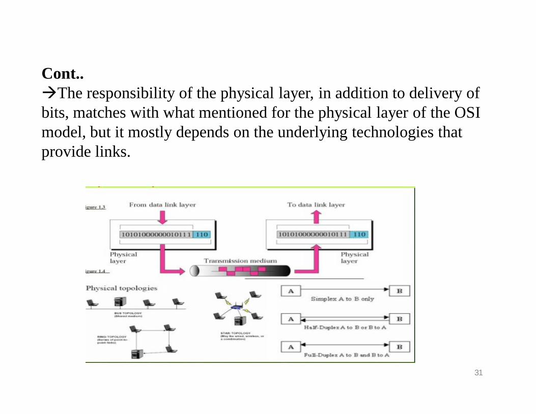
Cont..The responsibility of the physical layer, in addition to delivery of bits, matches with what mentioned for the physical layer of the OSI model, but it mostly depends on the underlying technologies that provide links.
31
2. Data Link Layer:
TCP/IP does not define any specific protocol for the data link layer either.
It supports all of the standard and proprietary protocols. At this level, the communication is also between two hops or nodes.
The unit of communication however, is a packet called aframe.
A frame is a packet that encapsulates the data received from the network layer with an added header and sometimes a trailer. The head includes the source and destination of frame.
32
Cont…
The destination address is needed to define the right recipient of the frame because many nodes may have been connected to the link.
The source address is needed for possible response or acknowledgment as may be required by some protocols.
The frame that is travelling between computer A and router R1 may be different from the one travelling between router R1 and R3.
When the frame is received by router R1, this router passes the frame to the data link layer protocol
The frame is opened, the data are removed.33

Figure: Data Link Layer
34
The data link layer protocol shown at the right to create a new frame to be sent to the router R3
The two nodes communicate logically at the data link layer, not physically.
In other words, the data link layer at router R1 only thinks that a frame has been sent directly from the data link layer at computer A, may be using different protocols and require frames of different formats.
A is transformed to a stream of bits, and the bits at R1 are transformed to a frame, it gives this impression to the two data link layer that a frame has been exchanged.
35

3. Network Layer
At the network layer (or, more accurately, the internetwork layer), TCP/IP supports the Internet Protocol (IP).
The Internet Protocol (IP) is the transmission mechanism used by the TCP/IP protocols.
IP transports data in packets called datagrams, each of whichis transported separately.
Datagrams can travel along different routes and can arrive out of sequence or be duplicated.
IP does not keep track of the routes and has no facility forreordering datagrams once they arrive at their destination.
36

Cont…
There is a main difference between the communication at the network layer and the communication at data link or physical layers. Communication at the network layer is end to end while the communication at the other two layers are node tonode. The datagram started at computer A is the one that reaches computer B. The network layers of the routers can inspect the source and destination of the packet for finding the best route, but they are not allowed to change the contents of the packet.. Although the network layer of computer A and B think that they are sending and receiving datagrams, the actual communication again is done at the physical level.
37

Figure: Network Layer
38
4. Transport Layer
There is a main difference between the transport layer and the network layer.
Although all nodes in a network need to have the network layer, only the two end computers need to have the transport layer.
The network layer is responsible for sendingindividual datagrams from computer A to computer B.
The transport layer is responsible for delivering the whole message, which is called a segment, a user datagram,or a packet, from A to B.
39
Cont…
A segment may consist of a few or tens of datagrams.
The segments need to be broken into datagrams and each datagram has to be delivered to the network layer for transmission.
Since the Internet defines a different route for each datagram, the datagrams may arrive out of order and may be lost.
The transport layer at computer B needs to wait until all of these datagrams to arrive.
40

Cont…
Traditionally, the transport layer was represented in the TCP/IP suite by two protocols:
1. User Datagram Protocol (UDP) and2. Transmission C1ontrol Protocol (TCP).
A new protocol called Stream Control Transmission Protocol (SCTP) has been introduced in the last few years.
41
5. Application Layer
The application layer in TCP/IP is equivalent to the combinedsession, presentation, and application layers in the OSI model.
The application layer allows a user to access the services ofour private internet or the global Internet.
Many protocols are defined at this layer to provide servicessuch as electronic mail, file transfer, accessing the World WideWeb, and so on.
42
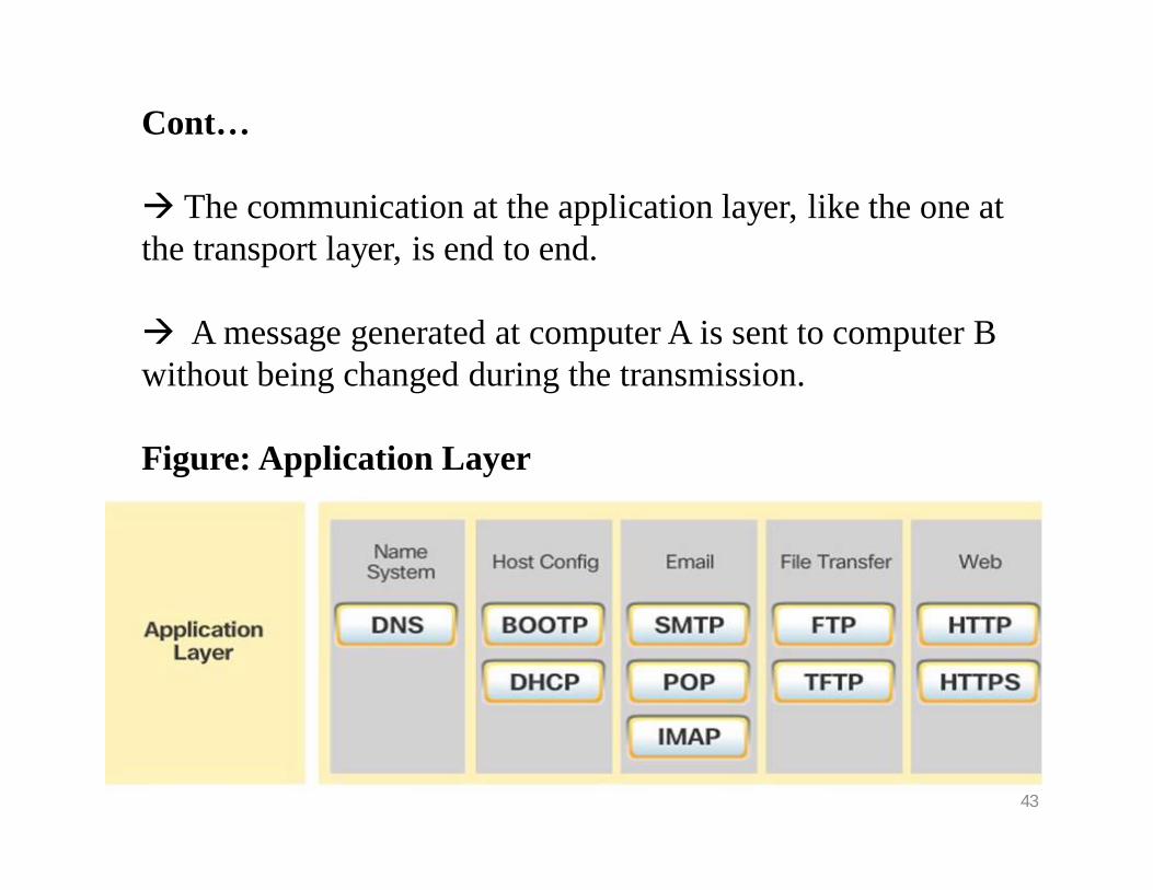
Cont…
The communication at the application layer, like the one at the transport layer, is end to end.
A message generated at computer A is sent to computer B without being changed during the transmission.
Figure: Application Layer
43

1.5 ADDRESSING
Four levels of addresses are used in an internet employing the TCP/IP protocols:
1. physical address, 2. logical address, 3. port address, 4. application-specific address.

1. Physical Addresses
The physical address, also known as the link address, is the address of a node as defined by its LAN or WAN.
It is included in the frame used by the data link layer. It is thelowest-level address.
The physical addresses have authority over the link (LAN orWAN). The size and format of these addresses vary depending on the network.
Ethernet uses a 6-byte (48-bit) physical address that is imprinted on the network interface card (NIC).
Unicast, Multicast, and Broadcast Physical Addresses:
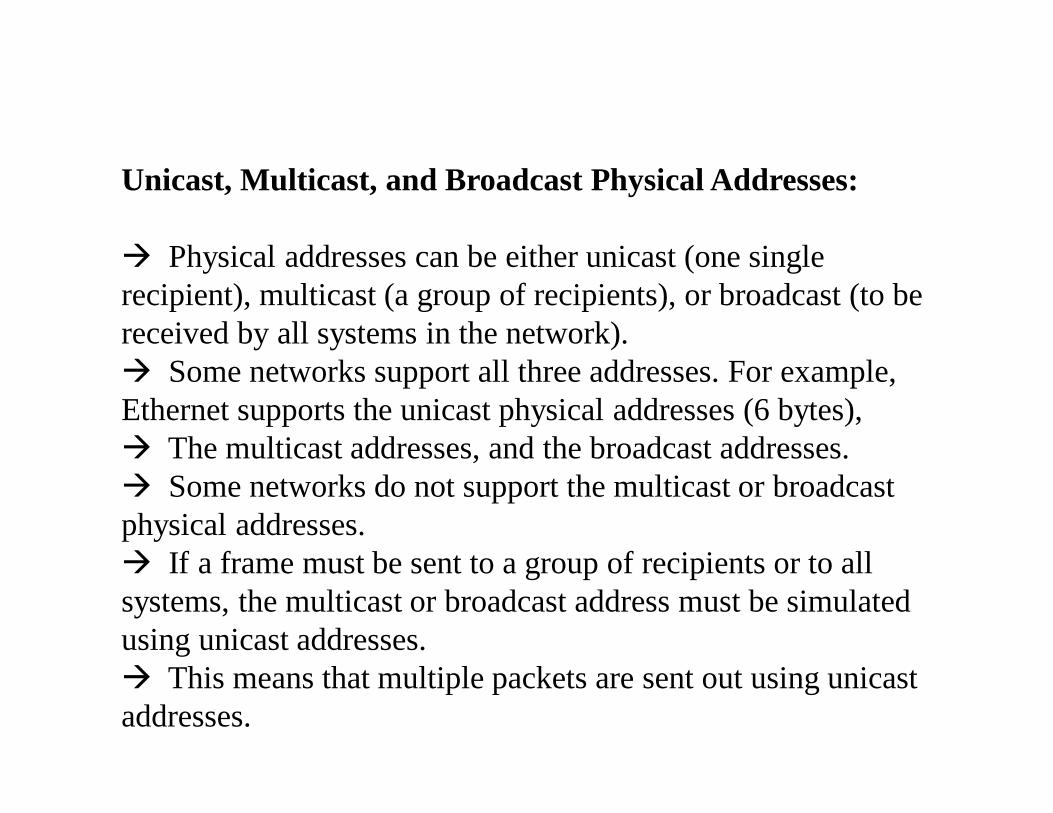
Physical addresses can be either unicast (one single recipient), multicast (a group of recipients), or broadcast (to be received by all systems in the network). Some networks support all three addresses. For example, Ethernet supports the unicast physical addresses (6 bytes), The multicast addresses, and the broadcast addresses. Some networks do not support the multicast or broadcast physical addresses. If a frame must be sent to a group of recipients or to all systems, the multicast or broadcast address must be simulated using unicast addresses. This means that multiple packets are sent out using unicastaddresses.

Figure: Physical Addresses
2. Logical Addresses
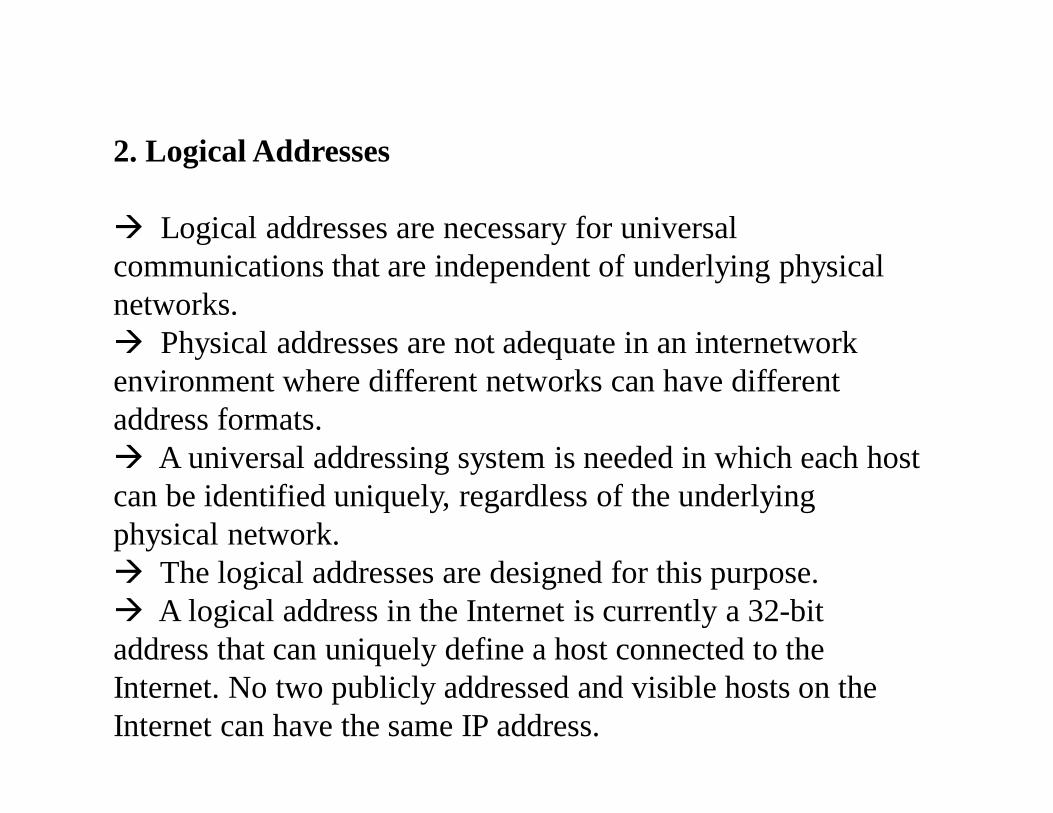
Logical addresses are necessary for universal communications that are independent of underlying physical networks. Physical addresses are not adequate in an internetworkenvironment where different networks can have different address formats. A universal addressing system is needed in which each host can be identified uniquely, regardless of the underlying physical network. The logical addresses are designed for this purpose. A logical address in the Internet is currently a 32-bit address that can uniquely define a host connected to the Internet. No two publicly addressed and visible hosts on the Internet can have the same IP address.
Unicast, Multicast, and Broadcast Addresses
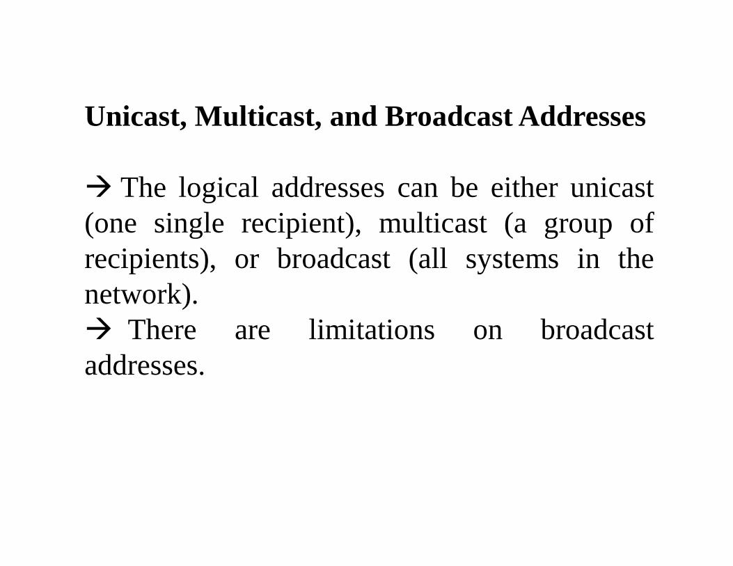
The logical addresses can be either unicast(one single recipient), multicast (a group ofrecipients), or broadcast (all systems in thenetwork). There are limitations on broadcastaddresses.

3. Port Addresses
The IP address and the physical address are necessary for aquantity of data to travel from a source to the destination host.
However, arrival at the destination host is not thefinal objective of data communications on the Internet.
A system that sends nothing but data from one computer toanother is not complete. Today, computers are devices that canrun multiple processes at the same time.
The end objective of Internet communication is a processcommunicating with another process. 3.
Cont…
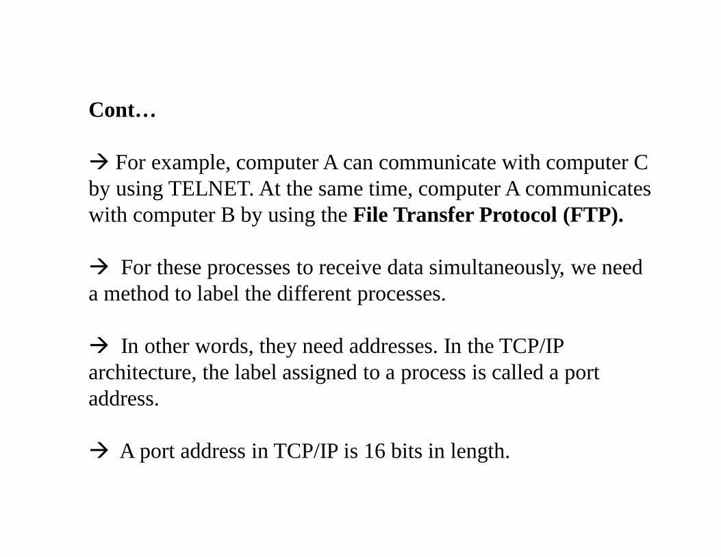
For example, computer A can communicate with computer C by using TELNET. At the same time, computer A communicates with computer B by using the File Transfer Protocol (FTP).
For these processes to receive data simultaneously, we need a method to label the different processes.
In other words, they need addresses. In the TCP/IP architecture, the label assigned to a process is called a port address.
A port address in TCP/IP is 16 bits in length.
4. Application-Specific Addresses
Some applications have user-friendly addresses that are designed for that specific application.
Examples include the e-mail address (for example, [email protected]) and the Universal Resource Locator (URL) (for example, www.mhhe.com).
The first defines the recipient of an e-mail; the second is used to find a document on the World WideWeb.
These addresses, however, get changed to the corresponding port and logical addresses by the sending computer.

1.5 CONNECTING DEVICES
LANs or WANs do not normally operate in isolation. They are connected to one another or to the Internet. To connect LANs and WANs together we use connectingdevices. Connecting devices can operate in different layers of the Internet model. We discuss three kinds of connecting devices: 1) repeaters (or hubs), 2) bridges (or two-layer switches), and 3) routers (or three-layer switches). Repeaters and hubs operate in the first layer of the Internet model. Bridges and two-layer switches operate in the first two layers. Routers and three-layer switches operate in the first three layers.
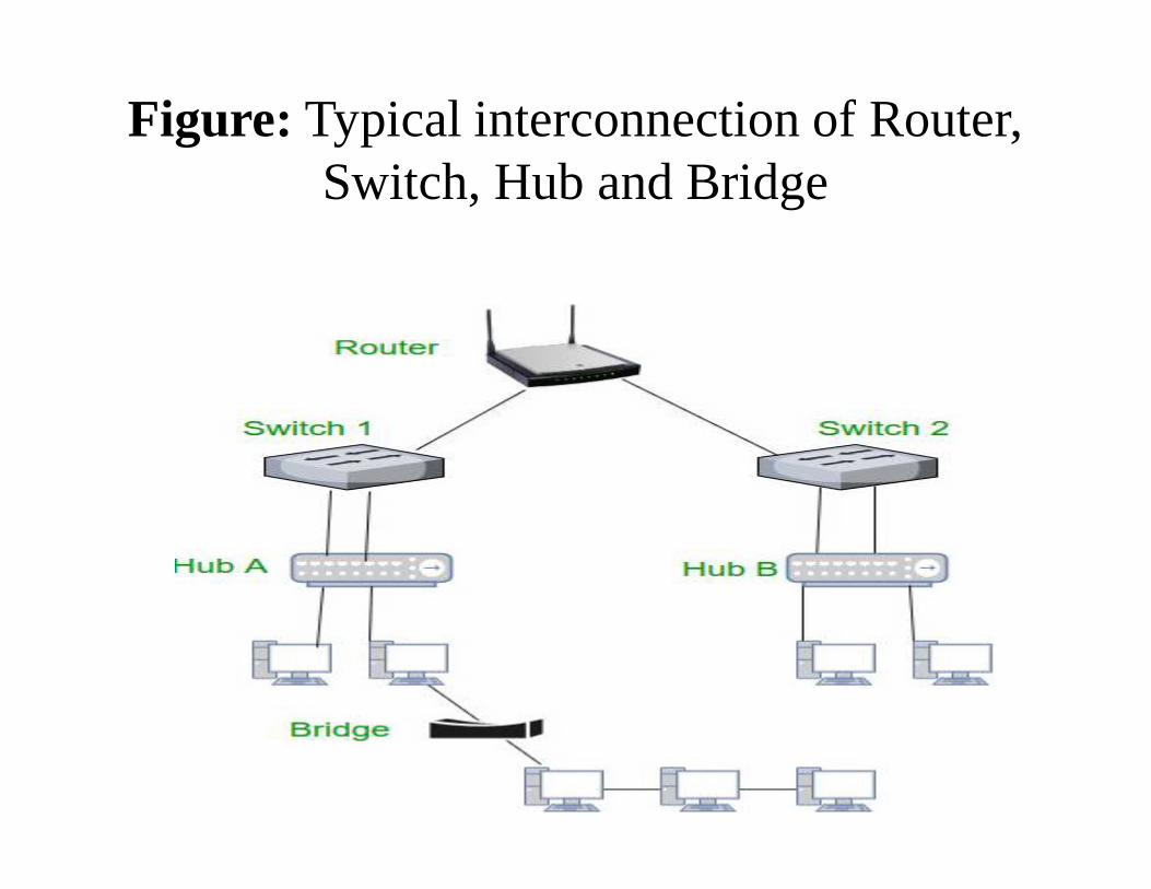
Figure: Typical interconnection of Router, Switch, Hub and Bridge

1) Repeaters:
A repeater is a device that operates only in the physicallayer. Signals that carry information within a network cantravel a fixed distance before attenuation endangers theintegrity of the data.
A repeater receives a signal and, before it becomes tooweak or corrupted, regenerates and retimes the original bitpattern.
The repeater then sends the refreshed signal. In thepast, when Ethernet LANs were using bus topology, arepeater
Cont…
Today, however, Ethernet LANs use star topology. In a star topology, a repeater is a multiport device, often called a hub, that can be used to serve as the connecting point and at the same time function as a repeater.
when a packet from station A to B arrives at the hub, the signal representing the frame is regenerated to remove any possible corrupting noise, but the hub forwards the packet from all outgoing port to all stations in the LAN.
In other words, the frame is broadcast. All stations in the LAN receive the frame, but only station B keeps it.
Bridges:
A bridge operates in both the physical and the data link layers.As a physical-layer device, it regenerates the signal it receives. As a data link layer device, the bridge can check the addresses (source and destination) contained in the frame.
Filtering:
One may ask what is the difference in functionality between a bridge and a repeater. A bridge has filtering capability. It can check the destination address of a frame and can decide from which outgoing port the frame should be send out.

Transparent Bridges:
A transparent bridge is a bridge in which the stations are completely unaware of the bridge’s existence.
If a bridge is added or deleted from the system, reconfiguration of the stations is unnecessary.
According to the IEEE 802.1d specification, a systemequipped with transparent bridges must meet three criteria:
1. Frames must be forwarded from one station to another.2. The forwarding table is automatically made by learning frame movements in the network.3. Loops in the system must be prevented.
Forwarding : A transparent bridge must correctly forward the frames, as discussed in the previous section.
Learning :
The earliest bridges had forwarding tables that were static. The system administrator would manually enter each table entry during bridge setup. Although the process was simple, it was not practical. If a station was added or deleted, the table had tobe modified manually. The same was true if a station’s MAC address changed, which is not a rare event.
1. When station A sends a frame to station D, the bridge does not have an entry for either D or A. The frame goes out from all three ports; the frame floods the network. However, by looking at the source address, the bridge learns that station A must be connected to port 1. This means that frames destined for A, in the future,must be sent out through port 1. The bridge adds this entry to its table. The table has its first entry now.
2. When station D sends a frame to station B, the bridge has no entry for B, so it floods the network again. However, it adds one more entry to the table.
3. The learning process continues until the table has information about every port.
Two-Layer Switch:
When we use the term switch, we must be careful because a switch can mean two differentthings.
We must clarify the term by adding the level at which the device operates.
We can have a two-layer switch or a three-layer switch.
A two-layer switch performs at the physical and data link layer; it is a sophisticated bridge with faster forwarding capability.
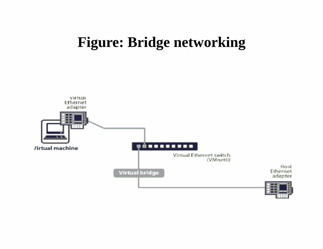
Figure: Bridge networking
Routers:
A router is a three-layer device; it operates in the physical, data link, and network layers.
As a physical layer device, it regenerates the signal it receives.
As a data link layer device, the router checks the physical addresses (source and destination) contained inthe packet.
As a network layer device, a router checks the network layer addresses (addresses in the IP layer). Note that bridges change collision domains, but routers limit broadcast domains.
There are three major differences between a router and a repeater or a bridge,
1. A router has a physical and logical (IP) address for each of its interfaces.
2. A router acts only on those packets in which the physical destination address matches the address of the interface at which the packet arrives.
3. A router changes the physical address of the packet (both source and destination) when it forwards the packet.
Three-Layer Switch:
A three-layer switch is a router; a router with an improved design to allow better performance.
A three-layer switch can receive, process, and dispatch a packet much faster than a traditional router even though the functionality is the same.
To avoid confusion, we use the term router for a three-layer switch.

1.6 CLASSFUL ADDRESSING
The identifier used in the IP layer of the TC/IP protocol suite is used to identify each device connected to internet is called Internet address or IP address.
At early few decades IP addresses use the concept of classes. This architecture is called classful addressing.
In the mid-1990s, a new architecture, calledclassless addressing, was introduced that supersedes the original architecture.
Classes:
In classful addressing, the IP address space is divided into five classes: A, B, C, D, and E.
Each class occupies some part of the whole address space.
Recognizing Classes:
We can find the class of an address, when the address is given either in binary or dotted decimal notation. In the binary notation, the first few bits can immediately tell the class of the address. In the dotted-decimal notation, the value of the first byte can give the class of an address .
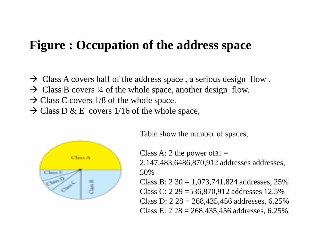
Figure : Occupation of the address space
Class A covers half of the address space , a serious design flow . Class B covers ¼ of the whole space, another design flow. Class C covers 1/8 of the whole space. Class D & E covers 1/16 of the whole space,
Table show the number of spaces,
Class A: 2 the power of31 = 2,147,483,6486,870,912 addresses addresses, 50%Class B: 2 30 = 1,073,741,824 addresses, 25%Class C: 2 29 =536,870,912 addresses 12.5%Class D: 2 28 = 268,435,456 addresses, 6.25%Class E: 2 28 = 268,435,456 addresses, 6.25%
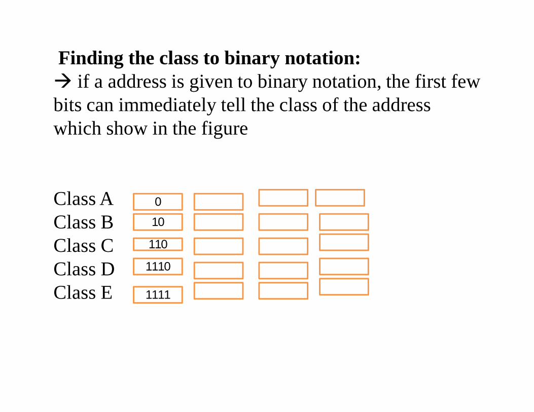
Finding the class to binary notation: if a address is given to binary notation, the first few bits can immediately tell the class of the address which show in the figure
Class A Class BClass CClass DClass E
10
1110
0
1111
110
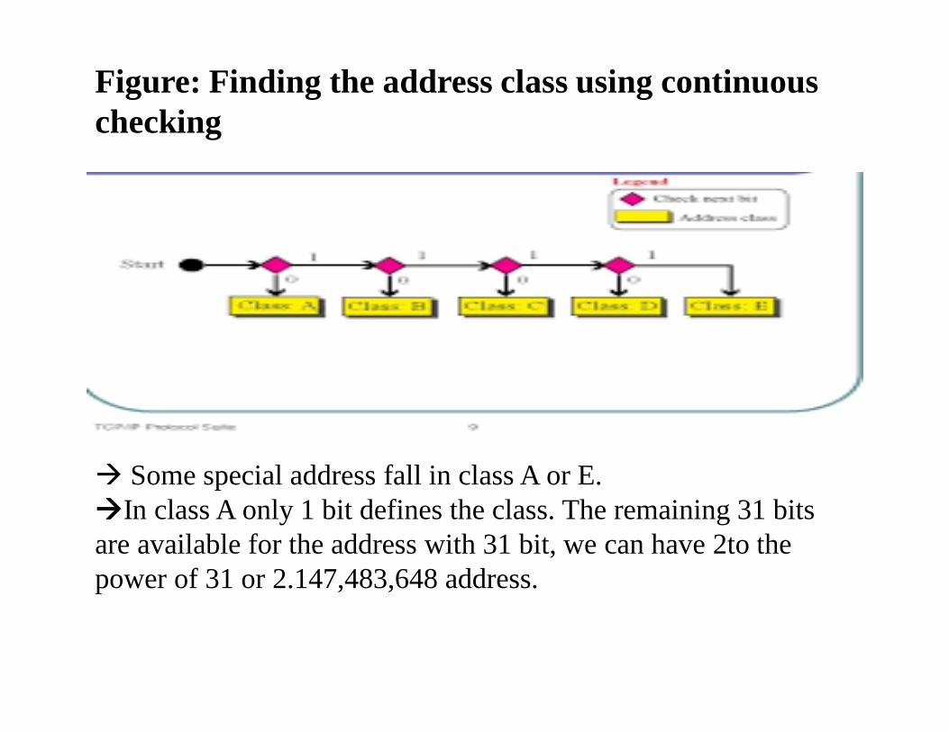
Figure: Finding the address class using continuous checking
Some special address fall in class A or E.In class A only 1 bit defines the class. The remaining 31 bits are available for the address with 31 bit, we can have 2to the power of 31 or 2.147,483,648 address.
egendCheck next bit
Addrs class

Finding the class to decimal notation:First byte of the class determine the class addressEach class has a specific range of numbers.Class A Class BClass CClass DClass E
128-191
224-239
0-127
240-255
192-223
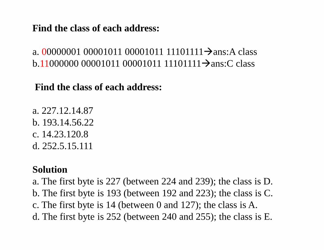
Find the class of each address:
a. 00000001 00001011 00001011 11101111ans:A classb.11000000 00001011 00001011 11101111ans:C class
Find the class of each address:
a. 227.12.14.87b. 193.14.56.22c. 14.23.120.8d. 252.5.15.111
Solutiona. The first byte is 227 (between 224 and 239); the class is D.b. The first byte is 193 (between 192 and 223); the class is C.c. The first byte is 14 (between 0 and 127); the class is A.d. The first byte is 252 (between 240 and 255); the class is E.

Netid and Hostid :
In classful addressing, an IP address in classes A, B, and C is divided into netid and hostid.The classes D and E are not divided into netid and hostid.
In class A, 1 byte defines the netid and 3 bytes define the hostid.
In class B, 2 bytes define the netid and 2 bytes define the hostid.
In class C, 3 bytes define the netid and 1 byte defines the hostid.
Classes and Blocks:
In classful addressing each class is divided into fixed to different netid.
One problem with classful addressing is that each class is divided into a fixed number of blocks with each block having a fixed size.

Figure: Netid and hostid
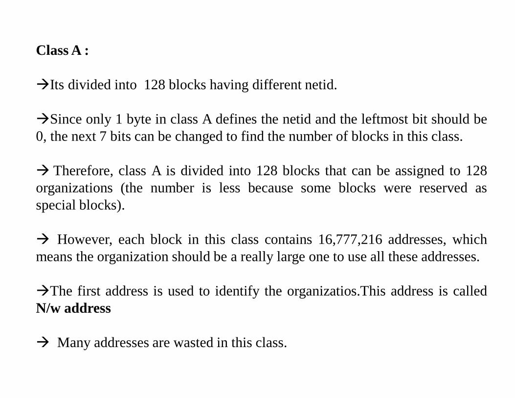
Class A :
Its divided into 128 blocks having different netid.
Since only 1 byte in class A defines the netid and the leftmost bit should be0, the next 7 bits can be changed to find the number of blocks in this class.
Therefore, class A is divided into 128 blocks that can be assigned to 128organizations (the number is less because some blocks were reserved asspecial blocks).
However, each block in this class contains 16,777,216 addresses, whichmeans the organization should be a really large one to use all these addresses.
The first address is used to identify the organizatios.This address is calledN/w address
Many addresses are wasted in this class.
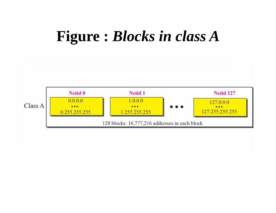
Figure : Blocks in class A
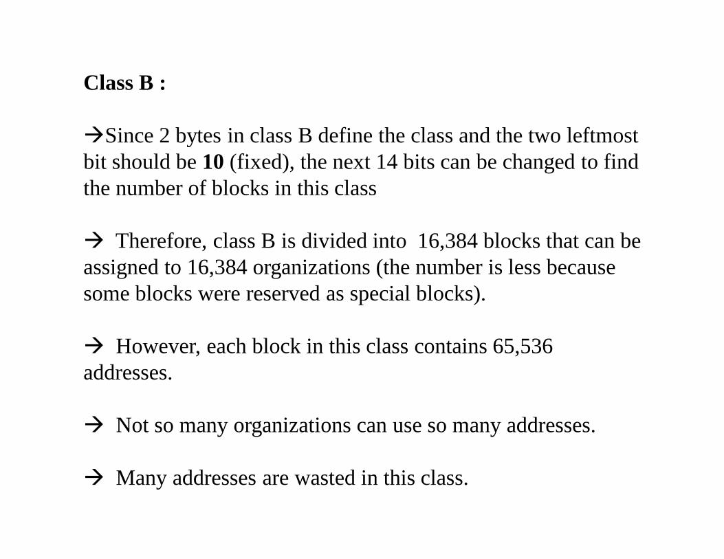
Class B :
Since 2 bytes in class B define the class and the two leftmost bit should be 10 (fixed), the next 14 bits can be changed to find the number of blocks in this class
Therefore, class B is divided into 16,384 blocks that can be assigned to 16,384 organizations (the number is less because some blocks were reserved as special blocks).
However, each block in this class contains 65,536 addresses.
Not so many organizations can use so many addresses.
Many addresses are wasted in this class.

Figure : Class B
Class C :
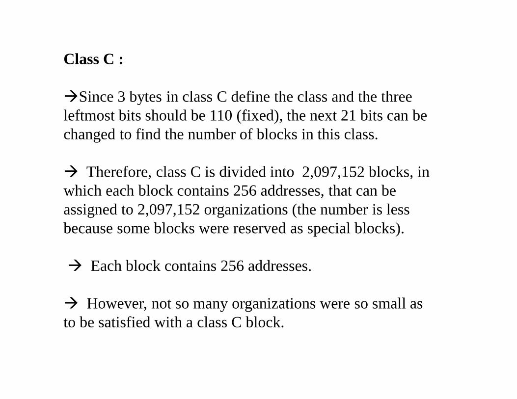
Since 3 bytes in class C define the class and the three leftmost bits should be 110 (fixed), the next 21 bits can be changed to find the number of blocks in this class.
Therefore, class C is divided into 2,097,152 blocks, in which each block contains 256 addresses, that can be assigned to 2,097,152 organizations (the number is less because some blocks were reserved as special blocks).
Each block contains 256 addresses.
However, not so many organizations were so small as to be satisfied with a class C block.
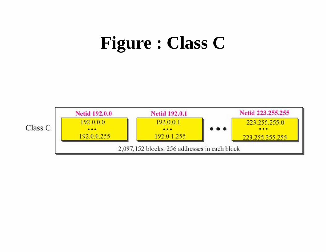
Figure : Class C

Class D : There is just one block of class D addresses. It is designed for multicasting. Each address in this class is used to define one group of hosts on the Internet. Class E: There is just one block of class E addresses. It was designed for use as reserved addresses.
SubnettingIn subnetting,a N/W is divided into several smaller subnet having its own subnetwork addressTwo-Level Addressing: The whole purpose of IPv4 addressing is to define a destination for an Internet packet (at the network layer).
When classful addressing was designed, it was assumed that thewhole Internet is divided into many networks and each network connects many hosts.
In other words, the Internet was seen as a network of networks.A network was normally created by an organization that wanted to be connected to the Internet.
The Internet authorities allocated a block of addresses to the organization (in class A, B, or C).
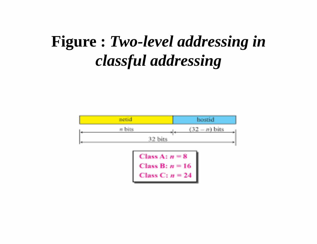
Figure : Two-level addressing in classful addressing

Extracting Information in a Block:
A block is a range of addresses. Given any address in the block, it provides three pieces of information about the block: the number of addresses, the first address, and the last address.
Before we can extract these pieces of information, weneed to know the class of the address, which we showed how to find in the previous section.
After the class of the block is found, we know the value of n, the length of netid in bits.
We can now find these three pieces of information
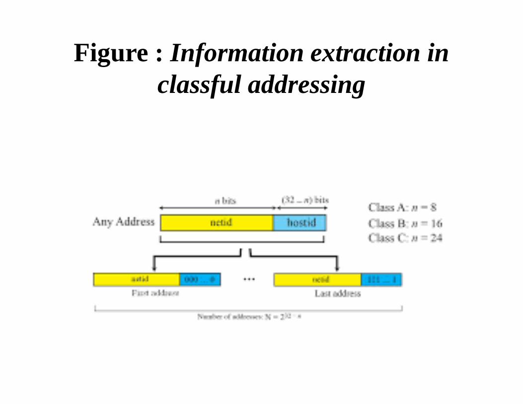
Figure : Information extraction in classful addressing
Network Address :
The above example show that, given any address, we can find all information about the block.
The first address ie. network address, is particularly important because it is used in routing a packet to its destination network.
For the moment, let us assume that an internet is made of m networks and a router with m interfaces.
When a packet arrives at the router from any source host, the router needs to know to which network the packet should be sent
The router needs to know from which interface the packet should be sent out. When the packet arrives at the network,
Network Mask :
The methods we described previously for extracting thenetwork address. The routers in the Internet normally use an algorithm toextract the network address from the destination address of apacket ie. network mask.
A network mask or a default mask in classful addressing is a32-bit number with n leftmost bits all set to 1s and (32 − n)rightmost bits all set to 0s.
Since n is different for each class in classful addressing,

Figure : Network Mask
Three-Level Addressing: Subnetting :
As we discussed before, the IP addresses were originallydesigned with two levels of addressing. To reach a host on the Internet, we must first reach thenetwork and then the host.First, an organization that was granted a block in class A orB needed to divide its large network into several subnetworksfor better security and management. Second, since the blocks in class A and B were almostdepleted and the blocks in class C were smaller than the needsof most organizations, an organization that has been granted ablock in class A or B could divide the block into smallersubblocks and share them with other organizations..

Subnet Mask
We discussed the network mask (default mask) before. Thenetwork mask is used when a network is not subnetted. Whenwe divide a network to several subnetworks, we need to createa subnetwork mask (or subnet mask) for each subnetwork..
Subnet AddressWhen a network is subnetted, the first address in the subnetis the identifier of the subnet and is used by the router to routethe packets destined for that subnetwork. Given any address in the subnet, the router can find thesubnet mask using the same procedure we discussed to find thenetwork mask, the given address with the subnet mask. Theshort cuts we discussed in the previous section can be used tofind the subnet address.

Figure : Network mask and subnetwork mask

Example :In Example 5.19, we show that a network is divided into four subnets. Since one of the addresses in subnet 2 is 141.14.120.77, we can find the subnet address as:
Address 141 14 120 77
Mask 255 255 192 0
Subnet Mask
141 14 64 0
The values of the first, second, and fourth bytes are calculated using the first short cut for AND operation. The value of the third byte is calculated using the second short cut for the ANDoperation.
Designing Subnets:
We show how to design a subnet when we discuss classless addressing.
Since classful addressing is a special case of classless addressing, what is discussed later can also be applied to classfuladdressing.
Subnetting could not completely solve address depletion problems in classful addressing because most organizations did not want to share their granted blocks with others.
Since class C blocks were still available but the size of the block did not meet the requirement of new organizations that wanted to join the Internet
Supernetting:
In supernetting, an organization can combine several class C blocks to create a larger range of addresses. In other words, several networks are combined to create a supernetwork. By doing this, an organization can apply for several class Cblocks instead of just one. For example, an organization that needs 1000 addresses can be granted four class C blocks.
Supernet Mask :
A supernet mask is the reverse of a subnet mask. A subnet mask for class C has more is than the default mask for this class. A supernet mask for class C has less 1s than thedefault mask for this class.
1.6 CLASSLESS ADDRESSING
Subnetting and supernetting in classful addressing did not really solve the address depletion problem and made the distribution of addresses and the routing process more difficult.
With the growth of the Internet, it was clear that a larger address space was needed as a long-term solution.
The larger address space, however, requires that thelength of IP addresses to be increased, which means the format of the IP packets needs to be changed.
The long-range solution has already been devised and is called IPv6.The short-term solution still uses IPv4 addresses, but it is called classless addressing. .

Cont…There was another motivation for classless addressing. During the 1990s, Internet service providers (ISPs) cameinto prominence.An ISP is an “organization that provides Internet access forindividuals, small businesses, and midsize organizations that donot want to create an Internet site and become involved inproviding Internet services (such as e-mail services) for theiremployees”.An ISP can provide these services. An ISP isgranted a large range of addresses and then subdivides theaddresses.In 1996, the Internet authorities announced a new architecturecalled classless addressing. In classless addressing, variable-length blocks are used thatbelong to no classes.We can have a block of 1 address, 2 addresses, 4 addresses,
Variable-Length Blocks :
In classful addressing the whole address space was dividedinto five classes.
Although each organization was granted one block in class A,B, or C, the size of the blocks was predefined; the organizationneeded to choose one of the three block sizes.
The only block in class D and the only block in class E werereserved for a special purpose.
In classless addressing, the whole address space is dividedinto variable length blocks.
Theoretically, we can have a block of 20, 21, 22, . . . , 232addresses..
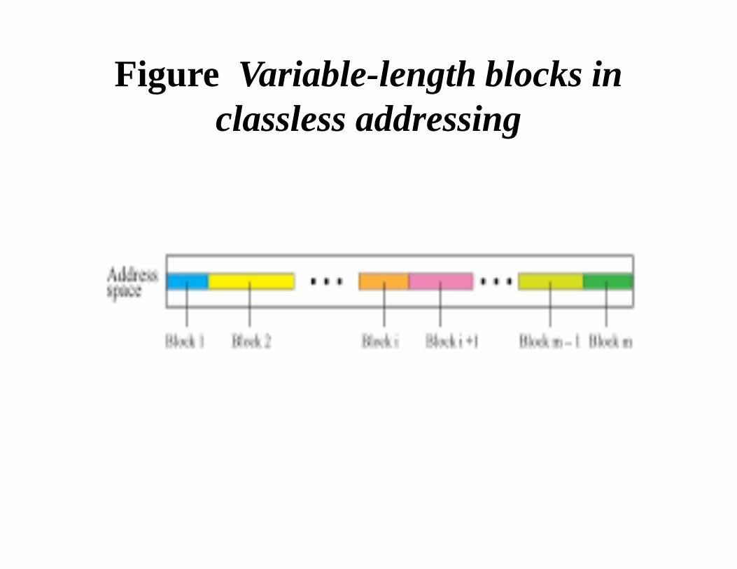
Figure Variable-length blocks in classless addressing
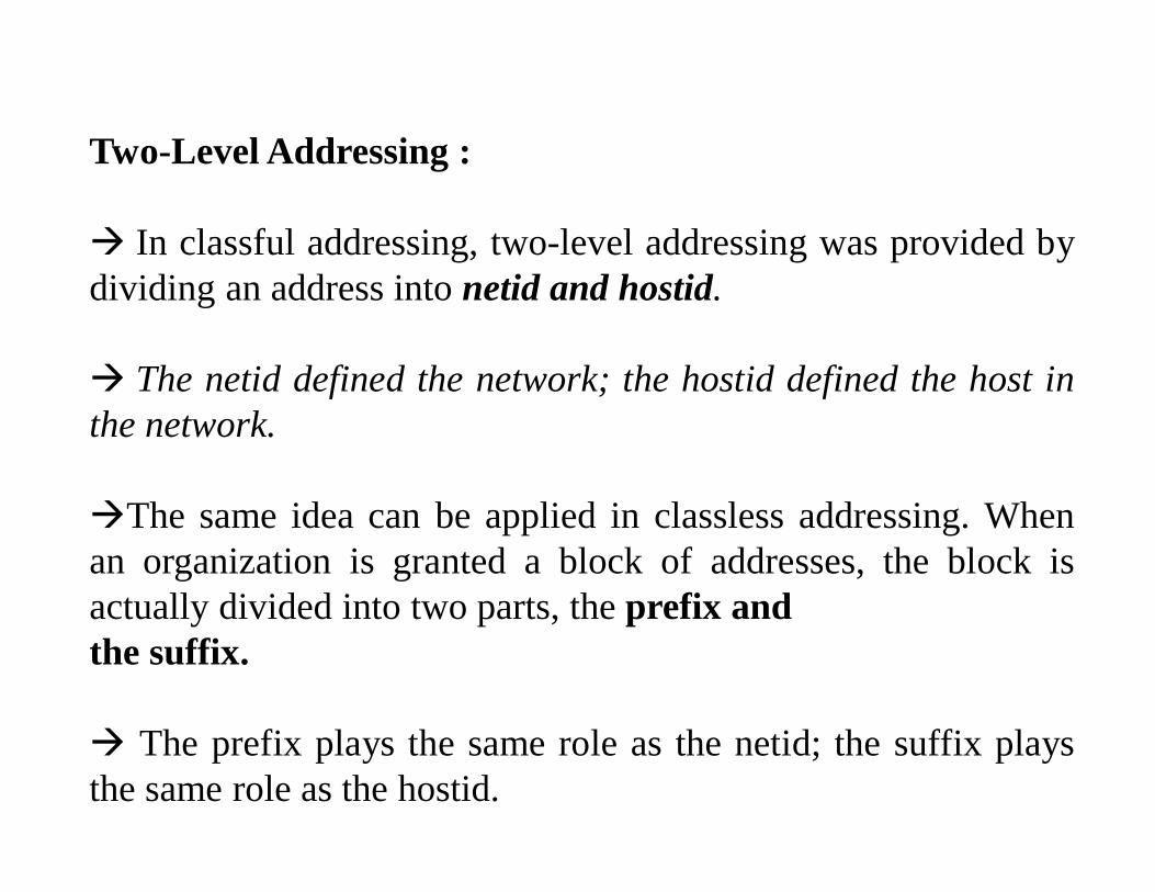
Two-Level Addressing :
In classful addressing, two-level addressing was provided bydividing an address into netid and hostid.
The netid defined the network; the hostid defined the host inthe network.
The same idea can be applied in classless addressing. Whenan organization is granted a block of addresses, the block isactually divided into two parts, the prefix andthe suffix.
The prefix plays the same role as the netid; the suffix playsthe same role as the hostid.

Figure Prefix and suffix
Slash Notation : The netid length in classful addressing or the prefix length in classless addressing is very important role to extract the information about the block from a given address in the block.
❑ In classful addressing, the netid length is inherent in the address. Given an address,we know the class of the address that allows us to find the netidlength (8, 16, or 24)❑ In classless addressing, the prefix length cannot be found if we are given only address in the block. The given address can belong to a block with any prefix length.
In classless addressing, we need to include the prefix length to each address if we need to find the block of the address.Ex.130.11.232.156/16 ie. The mask has 16 1s and 16 0s .The prefix length is 16 and suffix length is 16.

Network Mask : The idea of network mask in classless addressing is the same as the one in classful addressing. A network mask is a 32-bit number with the n leftmost bits all set to 0s and the rest of the bits all set to 1s.Extracting Block InformationAn address in slash notation is referred classless inter domain routing(CIDR) contains all information we need about the block:i.The first address (network address)ii. the number of addressesiii. and the last address.These three pieces of information can be found as follows:❑ The number of addresses in the block can be found as:
N =232 − n
N- no.of addresses in the block and n is the prefix lengthEx. 17.63.110.114/24 The network mask is 255.255.255.0
The first address is N=2 32-24
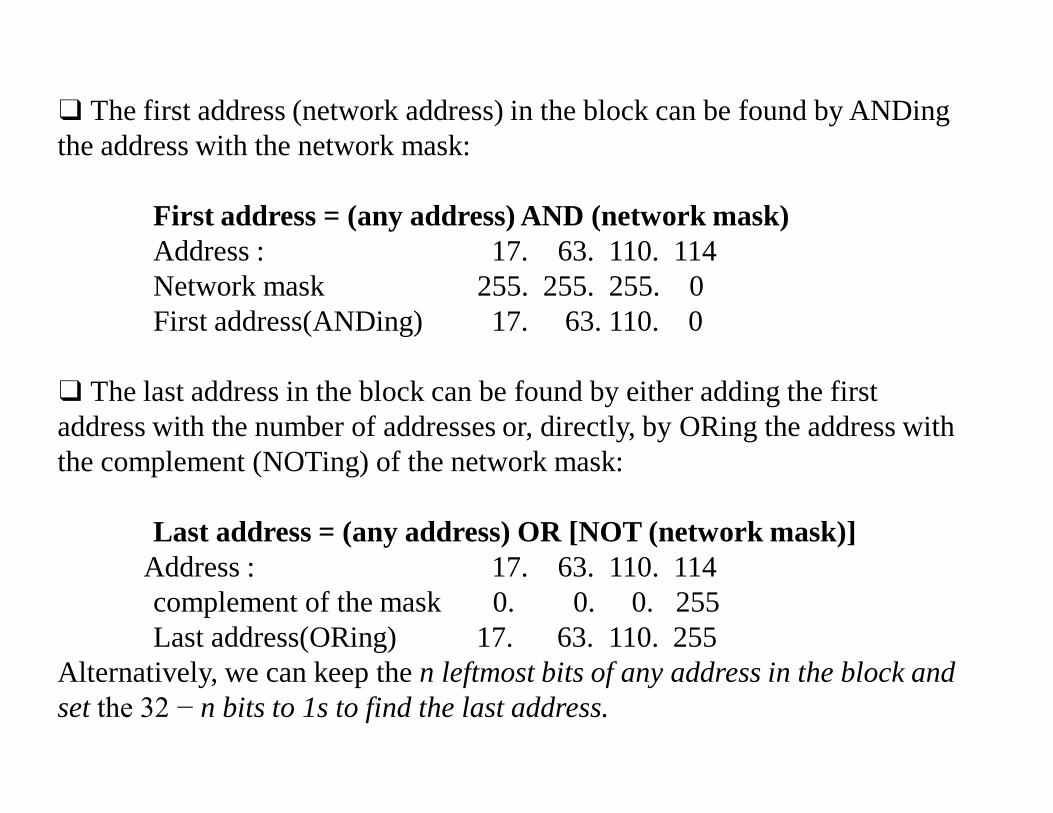
❑ The first address (network address) in the block can be found by ANDingthe address with the network mask:
First address = (any address) AND (network mask)Address : 17. 63. 110. 114Network mask 255. 255. 255. 0First address(ANDing) 17. 63. 110. 0
❑ The last address in the block can be found by either adding the first address with the number of addresses or, directly, by ORing the address with the complement (NOTing) of the network mask:
Last address = (any address) OR [NOT (network mask)]Address : 17. 63. 110. 114complement of the mask 0. 0. 0. 255 Last address(ORing) 17. 63. 110. 255
Alternatively, we can keep the n leftmost bits of any address in the block and set the 32 − n bits to 1s to find the last address.
Block Allocation:
The next issue in classless addressing is block allocation.
The ultimate responsibility of block allocation is given to a global authority called the Internet Corporation for Assigned Names and Addresses (ICANN) .
However, ICANN does not normally allocate addresses to individual Internet users.
It assigns a large block of addresses to an ISP (or a larger organization that is considered an ISP in this case).
For the proper operation of the CIDR, three restrictions need to be applied to the allocated block.
1. The number of requested addresses, N, needs to be a power of 2. This is needed to provide an integer value for the prefix length, n and the second restriction is the number of addresses can be 1, 2, 4, 8, 16, and so on.
2. The value of prefix length can be found from the number of addresses in the block.
Since N = 232 − n, then n = log2 (232/N) = 32 − log2N. That is the reason why N needs to be a power of 2.
3. The requested block needs to be allocated where there are a contiguous number of unallocated addresses in the address space.
However, there is a restriction on choosing the beginning addresses of the block. The beginning address needs to be divisible by the number of addresses in the block. To see this restriction, we can show that the beginning address can be calculated as X × 2n − 32 in which X is the decimal value of the prefix. In other words, the beginning address is X × N.
Relation to Classful Addressing :
All issues discussed for classless addressing can be applied to classful addressing.
As a matter of fact, classful addressing is a special case of the classless addressing in which the blocks in class A, B, and C have the prefix length nA = 8, nB = 16, and nC = 24.
A block in classful addressing can be easily changed to a block in class addressing if

Subnetting
Three levels of hierarchy can be created using subnetting. An organization (or an ISP) that is granted a range of addresses may divide the range into several subranges and assign each subrangeto a subnetwork (or subnet).
The concept is the same as we discussed for classfuladdressing.
A subnetwork can be divided into several sub-subnetworks.
A sub-subnetwork can be divided into several sub-sub-subnetworks. And so on.
Designing Subnets :
The subnetworks in a network should be carefully designed to enable the routing of packets. We assume the total number of addresses granted to the organization is N, the prefix length is n, the assigned number of addresses to each subnetwork is Nsub, the prefix length for each subnetwork is nsub, and the total number of subnetworks is s. Then, the following steps need to be carefully followed to guarantee the proper operation of the subnetworks.It should be followed
1. The number of addresses in each subnetwork should be a power of 2.2. The prefix length for each subnetwork should be found using the following formula:
nsub = n + log2 (N/Nsub)3. The starting address in each subnetwork should be divisible by the number of addresses in that subnetwork.

Finding Information about Each Subnetwork :
After designing the subnetworks, the information about each subnetwork, such as first and last address, can be found using the process.To identify the information about each network in the Internet address aggregation is used.
Address Aggregation:
One of the advantages of CIDR architecture is address aggregation. ICANN assigns a large block of addresses to an ISP.
Each ISP in turn divides its assigned block into smaller sublocksand grants the subblocks to its customers; many blocks of addresses are aggregated in one block and granted to one ISP.Many blocks of addresses are aggregated in one block and granted to one ISP.