el-dv.com · 1 Yaroslavl Electric Machine Building Plant Ордена Отечественной...
71
1 Yaroslavl Electric Machine Building Plant Ордена Отечественной войны I степени Открытое акционерное общество «Ярославский электромашиностроительный завод» (ОАО «ЭЛДИН») Система менеджмента качества сертифицирована по ГОСТ ISO 9001-2011 (ISO 9001:2008) Quality system is certificated according to GOST ISO 9001-2011 (ISO 9001:2008) Содержание Стр. Contents Page 1. Идентификационный код продукции..... 2. Введение................................................................................... 3. Вводные данные................................................................... 4. Вводные устройства. Конструктивные исполнения станин 5. Конструктивные исполнения электрических машин по способу монтажа ....................... 6. Уровни звукового давления и звуковой мощности.......... 7. Подшипники............................................................................ 8. Предельно-допустимые нагрузки........................................ 9. Показатели энергоэффективности ..................................... 10. Допустимый момент инерции нагрузки 11. Энергетические показатели 11.1. 3-фазные асинхронные двигатели по DIN................. 11.2. 3-фазные асинхронные двигатели по ГОСТ.............. 11.3. Многоскоростные двигатели....................................... 11.4. Двигатели с повышенным скольжением.................... 11.5. Двигатели с фазным ротором...................................... 11.6. 3-фазные асинхронные двигатели IP 23……… 11.7. Двигатели для привода лифтов................................... 11.8. 1-фазные асинхронные двигатели............................... 11.9. Двигатели постоянного тока....................................... 11.10. 3- фазные синхронные генераторы …………. 11.11. Двигатели со встроенным тормозом........................ 11.12. Допуски на установочно-присоединительные размеры двигателей.......................................... 12. Габаритные чертежи 12.1. IM 1001 - RA, A........................................................... 12.2. IM 2001 - RA, A........................................................... 12.3. IM 3001 - RA,A............................................................ 12.4. IM 3601 - RA,A............................................................ 12.5. IM 2101- RA,A............................................................. 12.6. Запасные части............................................................. 2 3 4 6 7 8 9 11 15 16 17 21 26 33 34 35 36 39 40 41 42 48 49 55 61 67 68 69 1. Identification production code......................................... 2. Preface................................................................................ 3. Introductory provisions.................................................... 4. Terminal boxes. Frame construction............................... 5. Type of construction and mounting of electrical machines...................................................................... 6. Levels of sound pressure and sound power..................... 7. Bearings............................................................................. 8. Permissible shaft load........................................................ 9. Energy efficiency data................................ 10. Allowable load inertia 11. Energy data 11.1. 3-phase induction motors to DIN............................. 11.2. 3-phase induction motors to GOST.......................... 11.3. Multi-speed motors..............................……………… 11.4. High slip motors....................................................... 11.5. Motors with phase-wound rotor............................... 11.6 3-phase induction motors IP 23 ................................ 11.7. Motors for lift drives................................................ 11.8. 1-phase induction motors......................................... 11.9. Direct current motors................................................ 11.10. 3-phase synchronous generators………………. 11.11. Built-in brake motors…………………………….. 11.12. Tolerance for overall dimensions of the motors............................................................... 12. Dimension drawings 12.1. IM B3 - RA,A.......................................................... 12.2. IM B35 - RA,A........................................................ 12.3. IM B5 - RA,A.......................................................... 12.4. IM B14 - RA,A........................................................ 12.5. IM B34 - RA,A........................................................ 12.6. Spare parts…………………………………………. 2 3 4 6 7 8 9 11 15 16 17 17 21 26 33 34 35 36 39 40 41 42 48 49 55 61 67 68 69 Редакция 24.11.2016 - - - - - - - - - - - - - - - - - - - - - - - - - - - - - - - - - - - Russia, 150040, Yaroslavl, Prosp. Oktyabrya, 74 tel: +7 (4852) 78-00-00, 78-01-91 fax: +7 (4852) 78-00-01 e-mail: [email protected], internet: http://www.eldin.ru - - - - - - - - - - - - - - - - - - - - - - - - - - - - - - - - - - - - - - Россия, 150040, г. Ярославль, проспект Октября, 74 тел.: (4852) 78-00-00,78-01-10 факс: (4852) 78-00-01 e-mail: [email protected], internet: http://www.eldin.ru
Transcript of el-dv.com · 1 Yaroslavl Electric Machine Building Plant Ордена Отечественной...
1
Yaroslavl Electric Machine Building Plant
Ордена Отечественной войны I степени
Открытое акционерное общество
«Ярославский электромашиностроительный завод»
(ОАО «ЭЛДИН»)
Система менеджмента качества
сертифицирована по
ГОСТ ISO 9001-2011 (ISO 9001:2008)
Quality system is certificated
according to
GOST ISO 9001-2011 (ISO 9001:2008)
Содержание
Стр.
Contents
Page
1. Идентификационный код продукции.....
2. Введение.....................................................................................
3. Вводные данные...................................................................
4. Вводные устройства. Конструктивные исполнения
станин
5. Конструктивные исполнения электрических
машин по способу монтажа .......................
6. Уровни звукового давления и звуковой мощности...........
7. Подшипники..............................................................................
8. Предельно-допустимые нагрузки..........................................
9. Показатели энергоэффективности .......................................
10. Допустимый момент инерции нагрузки
11. Энергетические показатели
11.1. 3-фазные асинхронные двигатели по DIN....................
11.2. 3-фазные асинхронные двигатели по ГОСТ.................
11.3. Многоскоростные двигатели.........................................
11.4. Двигатели с повышенным скольжением....................
11.5. Двигатели с фазным ротором........................................
11.6. 3-фазные асинхронные двигатели IP 23………
11.7. Двигатели для привода лифтов.....................................
11.8. 1-фазные асинхронные двигатели.................................
11.9. Двигатели постоянного тока.........................................
11.10. 3- фазные синхронные генераторы ………….
11.11. Двигатели со встроенным тормозом...........................
11.12. Допуски на установочно-присоединительные
размеры двигателей..........................................
12. Габаритные чертежи
12.1. IM 1001 - RA, A.............................................................
12.2. IM 2001 - RA, A.............................................................
12.3. IM 3001 - RA,A..............................................................
12.4. IM 3601 - RA,A..............................................................
12.5. IM 2101- RA,A...............................................................
12.6. Запасные части...............................................................
2
3
4
6
7
8
9
11
15
16
17
21
26
33
34
35
36
39
40
41
42
48
49
55
61
67
68
69
1. Identification production code...........................................
2. Preface..................................................................................
3. Introductory provisions.......................................................
4. Terminal boxes. Frame construction..................................
5. Type of construction and mounting of electrical
machines......................................................................
6. Levels of sound pressure and sound power........................
7. Bearings................................................................................
8. Permissible shaft load..........................................................
9. Energy efficiency data................................
10. Allowable load inertia
11. Energy data
11.1. 3-phase induction motors to DIN...............................
11.2. 3-phase induction motors to GOST............................
11.3. Multi-speed motors..............................………………
11.4. High slip motors.........................................................
11.5. Motors with phase-wound rotor..................................
11.6 3-phase induction motors IP 23 ..................................
11.7. Motors for lift drives...................................................
11.8. 1-phase induction motors............................................
11.9. Direct current motors..................................................
11.10. 3-phase synchronous generators……………….
11.11. Built-in brake motors……………………………..
11.12. Tolerance for overall dimensions of the
motors...............................................................
12. Dimension drawings
12.1. IM B3 - RA,A............................................................
12.2. IM B35 - RA,A..........................................................
12.3. IM B5 - RA,A............................................................
12.4. IM B14 - RA,A..........................................................
12.5. IM B34 - RA,A..........................................................
12.6. Spare parts…………………………………………..
2
3
4
6
7
8
9
11
15
16
17
17
21
26
33
34
35
36
39
40
41
42
48
49
55
61
67
68
69
Редакция 24.11.2016
- - - - - - - - - - - - - - - - - - - - - - - - - - - - - - - - - - -
Russia, 150040, Yaroslavl, Prosp. Oktyabrya, 74
tel: +7 (4852) 78-00-00, 78-01-91
fax: +7 (4852) 78-00-01
e-mail: [email protected], internet: http://www.eldin.ru
- - - - - - - - - - - - - - - - - - - - - - - - - - - - - - - - - - - - - -
Россия, 150040, г. Ярославль, проспект Октября, 74
тел.: (4852) 78-00-00,78-01-10
факс: (4852) 78-00-01
e-mail: [email protected], internet: http://www.eldin.ru
2
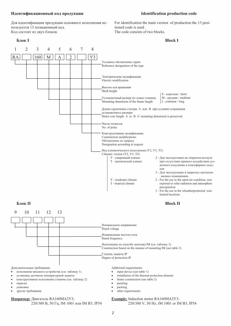
��������������� ��� ��������� Identification production code
��� ����������� ������� ��������� �� ������� ��-
��������� 13 ���������� ��.
��� ������� �� ���� �����.
For identification the main version of production the 13 posi-
tioned code is used .
The code consists of two blocks.
���� I Block I
1 2 3 4 5 6 7 8
RA 160 M A 2 �3�������� ����������� �����
Reference designation of the type
����������� ���������
Electric modification
������ ��� ��� ����
Shaft height
������������ ������ � ����� �������
Mounting dimension of the frame length
����� ��������� ������� ! ��� � �� ������� ����������
������������� �������
Stator core length ! or � if mounting dimension is preserved
"���� ��#���
No. of poles
������������� ���������
Construction modifications
$���������� � �� ����
Designation according to request
��� ������������ �� ������� (�2, �3, %2)
Climatic version (Y2, Y3, %2)
� - ��������� �����
% - ��� ������ �����
2 - ��� &� �������� �� ������� �������
�� ���������� ������ ����������� ���-
������� ��������� � ���������� ����-
��
3 - ��� &� �������� � ������� ����� ��-
������ ��� �����.
� - moderate climate
% - tropical climate
2 - For the use in the open-air-condition, non
exposed to solar radiation and atmosphers
precipitation
3 - For the use in the wheatherprotected non-
heated locations
���� II Block II
9 10 11 12 13
'���������� �� ��(����
Rated voltage
'���������� ������� ����
Rated frequency
)� ������� � � ����� �����(� IM (��. ������� 3)
Construction based on the manner of mounting IM (see table 3)
*�� ��� �� ��� IP
Degree of protection IP
�� ����������� ����������:
• �� ������� �������� ���������� (��. ������� 1)
• �������� ������� ��� ��������� �� ���
• ������������ �� ������� ������� (��. ������� 2)
• �����
• � ����
• ������ ����������
Additional requirements:
• input device (see table 1)
• installation of the thermal protection element
• frame construction (see table 2)
• painting
• packing
• other requirements
�������: ��������� RA160MA2�3;
220/380 �, 50 +�, IM 1001 ��� IM B3, IP54
Example: Induction motor RA160MA2�3;
220/380 V, 50 Hz, IM 1001 or IM B3, IP54
S - ������ / short
M - ������� / medium
L -������� / long
3
�������� ������������ ���� � � ��������� ��������� �����-
��� ��������� ��� �� �� ��� ������� ��������-
����. �� ������������� ��� ����� ������������
������ ���. ������������� ���������� ��������
����������� ���� ������ ��� ��� «�� ��» ��������
���!������� ����!����� � ���� "������������ ����-
�����, ������ ���������� �����, �!������� ���!�-
����# ��$��� ���"%��$�# �� �, ���"���&�����#
�� �%����.
'�"������ �������� ����� �� "�$�� ����"$��-
��:
• �������� �������������� !���� ��� ������ ()
• "����������� ��������� � ��%���� ��� ���
���� �� !���� ��� ���#���" �������� � ���-
��� ��$��� IP54 ��� IP55 � ��������� *����� ��
• �����%���� �������# ����!�� - ����", ���� ���
����
• ��������# ��� ���"���&��, �� �%���� � �����-
���"� �����"����"� ��!���� !���� ��� ����-
����� �����&�� ���� ���������#���� F (�������
�!����� �������� � 85 °C)
• ��%����� ��"������� ���������
������ � ����� ���
�������� �������� ��������"�$�� ��&��������� �
��% "���� ��� ��� ����� � �� ������.
����� ����� ��� � ���������� �����
�������� ����������� ���������� ���� �����������-
�"��� ������� ��"����� � �"� ���������.
�� ���� RA - ��� �&�� ��$���� � ���� ����������
�������� � DIN EN 50347.
�� ���� A, ��� - ��� �&�� ��$���� � ���� ���-
������� �������� � +�,- 31606.
��������� � ����������
�������� ��!%��� �� �������� ������������� ��
������ ��� ������������ ����, ��!����$���
��������� �� ���������� ���$����.
�� ���
�"����� ����� ��!��&�� ��������# "��������� �
+�,- IEC 60034-14-2014.
' ������� �������� - ����� ��!��&�� �.
)� �����" - ����� ��!��&�� B.
'� ������ ��������# ��������� !������"���
��"�����#.
�����! ����
��������� "����� ��"�� ������ ��� � +�,- 11929
(DIN EN 21680 ���� 1) � ��%��� �������� �� � ��
����������� ����%���� � ������ ���.
�� �
,��� ������ ������ ��������"�� "������� ��������#
� ���$����� ��� � ������ �� �������� ��� "�� ��
"�������# �������"��. .��� - RAL 5017 (���������#).
"���� ��
�������� ����� ����� � ��� � �����, �������-
��� � +�,- 23360, �������� 2 (DIN 6885, ����� ').
���� ����� �������� +�,- 23360 (DIN 748, ���� 3).
�������� ��������� ���%����# �����#.
)� ���!� ��������� �������� ���"� !��� �����������
�"�� ���&��� ����.
)��� ������� ��$���� �� ������� ���&� ���� - � ��-
��".
���%������� �� ��� �������� ���� � (����, �"���)
���!�� ��� ��!����������� "����� !���������� ��-
���� ��������.
Introduction Electrical drives in their many variations are now in use in
every branch of industry. Their characteristics determine the
efficiency of production. Low voltage three-phase asynchronous
motors of ELDIN production meet the needs of customer with
regard to all-round versatility, superior performance parameters,
environmental compatibility and a high standard of reliability.
The motors produced by have the following advantages:
• energy savings, due to high motor efficiencies
• versatility of application and reduction of stock due to series
version in IP 54 or IP 55 degree of protection and the use of
the removable feet
• terminal box position - top, right or left
• increased lifetime, reliability and thermal overload capacity
owing to insulation class F (overheating of the motor wind-
ing - 85° C)
• reduced acoustic indexes
Standards and regulations
The motors comply with the relevant national and international
standards and regulations.
Correspondence between power and overall dimensions
Three-phase asynchronous motors with squirrel cage rotor are
produced in two versions.
Power and mounting dimensions gradation for the series RA as
specified in DIN EN 50347.
Power and mounting dimensions gradation for the series A,
�IR as specified in GOST 31606.
Cooling and ventilation
Motors are equipped with radial plastic or aluminium alloy fans
which cool the motor, whatever its direction of rotation.
Vibration characteristics
The permissible vibration intensities of electric motors are
specified in GOST IEC 60034-14-2014.
In the basic version - vibration intensity stage A.
By order - vibration intensity stage B.
All rotors are dinamically balanced with a half key.
Noise level
Noise measurement is carried out as specified in GOST 11929
(DIN EN 21680, part 1) under no-load operation at rated volt-
age and rated freguency.
Painting
Standard painting corresponds to the wheatherprotected and
non-wheatherprotected locations, open-air-conditions at the
moderate temperature. Colour - RAL 5017 (blue).
Shaft end
The motors are supplied with keys and slots for the keys as
specified in GOST 23360, version 2 (DIN 6885, shape B). The
lenght of the key is as specified in GOST 23360 (DIN 748, part
3). The motors are supplied with key fitted.
The motors with two shaft ends are available on request.
The power transmitted for the second shaft end is available on
request.
The drive elements used, such as belt pulleys or couplings are
to be balanced with the rotor balancing taken into consideration.
4
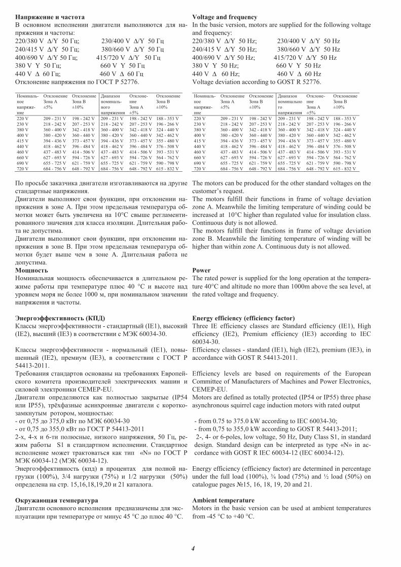
��������� ��� ��
� �������� �������� ���� �� ���������� �� � -
������� � � �����:
220/380 V ∆/Y 50 ��; 230/400 V ∆/Y 50 ��
240/415 V ∆/Y 50 ��; 380/660 V ∆/Y 50 ��
400/690 V ∆/Y 50 ��; 415/720 V ∆/Y 50 ��
380 V Y 50 ��; 660 V Y 50 ��
440 V ∆ 60 ��; 460 V ∆ 60 ��
������� � ������� �� ���� � 52776.
����� �-
��
� ����-
��
�������
��� �
±5%
�������
��� �
±10%
� � !��
����� �-
����
� �������
�����-
��
��� �
±5%
�������
��� �
±10%
220 V 209 - 231 V 198 - 242 V 209 - 231 V 198 - 242 V 188 - 353 V
230 V 218 - 242 V 207 - 253 V 218 - 242 V 207 - 253 V 196 - 266 V
380 V 360 - 400 V 342 - 418 V 360 - 400 V 342 - 418 V 324 - 440 V
400 V 380 - 420 V 360 - 440 V 380 - 420 V 360 - 440 V 342 - 462 V
415 V 394 - 436 V 373 - 457 V 394 - 436 V 373 - 457 V 355 - 480 V
440 V 418 - 462 V 396 - 484 V 418 - 462 V 396 - 484 V 376 - 508 V
460 V 437 - 483 V 414 - 506 V 437 - 483 V 414 - 506 V 393 - 531 V
660 V 627 - 693 V 594 - 726 V 627 - 693 V 594 - 726 V 564 - 762 V
690 V 655 - 725 V 621 - 759 V 655 - 725 V 621 - 759 V 590 - 798 V
720 V 684 - 756 V 648 - 792 V 684 - 756 V 648 - 792 V 615 - 832 V
"� �����# ! � !��� ���� �� �!��� ��� ���� � ��$��
�� �� ���� � �������.
��� �� �������� ���� %$�����, ��� �������� � -
������� � !�� �. "�� &��� ����� � ���� �$� �#-
����� ���� #��� $���� � 10°� ���' �� ����-
��� ����� !� ���� �� � �� �!�����. ���� � � #�-
� � ���$���� .
��� �� �������� ���� %$�����, ��� �������� � -
������� � !�� �. "�� &��� ����� � ���� �$� �#-
����� #$�� ��' �� � !�� �. ���� � � #�� �
���$���� .
Voltage and frequency
In the basic version, motors are supplied for the following voltage
and frequency:
220/380 V ∆/Y 50 Hz; 230/400 V ∆/Y 50 Hz
240/415 V ∆/Y 50 Hz; 380/660 V ∆/Y 50 Hz
400/690 V ∆/Y 50 Hz; 415/720 V ∆/Y 50 Hz
380 V Y 50 Hz; 660 V Y 50 Hz
440 V ∆ 60 Hz; 460 V ∆ 60 Hz
Voltage deviation according to GOST R 52776.
����� �-
��
� ����-
��
�������
��� �
±5%
�������
��� �
±10%
� � !��
����� ���
��
� �������
�����-
��
��� �
±5%
�������
��� �
±10%
220 V 209 - 231 V 198 - 242 V 209 - 231 V 198 - 242 V 188 - 353 V
230 V 218 - 242 V 207 - 253 V 218 - 242 V 207 - 253 V 196 - 266 V
380 V 360 - 400 V 342 - 418 V 360 - 400 V 342 - 418 V 324 - 440 V
400 V 380 - 420 V 360 - 440 V 380 - 420 V 360 - 440 V 342 - 462 V
415 V 394 - 436 V 373 - 457 V 394 - 436 V 373 - 457 V 355 - 480 V
440 V 418 - 462 V 396 - 484 V 418 - 462 V 396 - 484 V 376 - 508 V
460 V 437 - 483 V 414 - 506 V 437 - 483 V 414 - 506 V 393 - 531 V
660 V 627 - 693 V 594 - 726 V 627 - 693 V 594 - 726 V 564 - 762 V
690 V 655 - 725 V 621 - 759 V 655 - 725 V 621 - 759 V 590 - 798 V
720 V 684 - 756 V 648 - 792 V 684 - 756 V 648 - 792 V 615 - 832 V
The motors can be produced for the other standard voltages on the
customer�s request.
The motors fulfill their functions in frame of voltage deviation
zone A. Meanwhile the limiting temperature of winding could be
increased at 10°� higher than regulated value for insulation class.
Continuous duty is not allowed.
The motors fulfill their functions in frame of voltage deviation
zone �. Meanwhile the limiting temperature of winding will be
higher than within zone �. Continuous duty is not allowed.
� �� ���
����� �� � ��(����� �#����� ��� � ������� �-
��� � #��� ��� ���� �$� ��� 40 °� � ����� � �
$����� ���� � #� 1000 �, ��� ����� ���� !� ����
� ������� � � �����.
����� �������� ��� (���)
) ��� &����&%%��������� - �� �� ����* (IE1), ������*
(IE2), ���'�* (IE3) � ����������� � +,) 60034-30.
) ��� &����&%%��������� - ���� ���* (IE1), ����-
'���* (IE2), ����$� (IE3), � ����������� � ���� �
54413-2011.
��#�� ��� �� �� ���� ����� �� � ��#�� ���- .����*-
����� ������ ����!�����* &��������- � '�� �
�����* &�������� �.+.�-EU.
��� �� ��������� � � �������� ! ����� (IP54
�� IP55), ��/-% !�� ���-����� ���� �� � �������-
! ���$��� �������, ��(������:
- �� 0,75 �� 375,0 ��� �� +,) 60034-30
- �� 0,75 �� 355,0 ��� �� ���� � 54413-2011
2--, 4-- � 6-�� ������, ��!���� � �������, 50 ��, �-
��� � #��� S1 � �� �� ����� ��������. �� �� ����
������� ���� �� ���� ���� � � ��� «N» �� ���� �
+,) 60034-12 (+,) 60034-12).
,����&%%��������� (���) � ������ - �� ����* � -
��$!�� (100%), 3/4 � ��$!�� (75%) � 1/2 � ��$!�� (50%)
����� � ���. 15,16,18,19,20 � 21 � � �� .
���������� �����������
��� �� ��������� �������� ���� !� ��� �� &��-
�$ � ��� ��� ���� �$� �� ���$� 45 °� �� ��� 40 °�.
Power
The rated power is supplied for the long operation at the tempera-
ture 40°C and altitude no more than 1000m above the sea level, at
the rated voltage and frequency.
Energy efficiency (efficiency factor)
Three IE efficiency classes are Standard efficiency (IE1), High
efficiency (IE2), Premium efficiency (IE3) according to IEC
60034-30.
Efficiency classes - standard (IE1), high (IE2), premium (IE3), in
accordance with GOST R 54413-2011.
Efficiency levels are based on requirements of the European
Committee of Manufacturers of Machines and Power Electronics,
CEMEP-EU.
Motors are defined as totally protected (IP54 or IP55) three phase
asynchronous squirrel cage induction motors with rated output
- from 0.75 to 375.0 kW according to IEC 60034-30;
- from 0,75 to 355,0 kW according to GOST R 54413-2011;
2-, 4- or 6-poles, low voltage, 50 Hz, Duty Class S1, in standard
design. Standard design can be interpreted as type «N» in ac-
cordance with GOST R IEC 60034-12 (IEC 60034-12).
Energy efficiency (efficiency factor) are determined in percentage
under the full load (100%), ¾ load (75%) and ½ load (50%) on
catalogue pages 015, 16, 18, 19, 20 and 21.
Ambient temperature
Motors in the basic version can be used at ambient temperatures
from -45 °C to +40 °C.
5
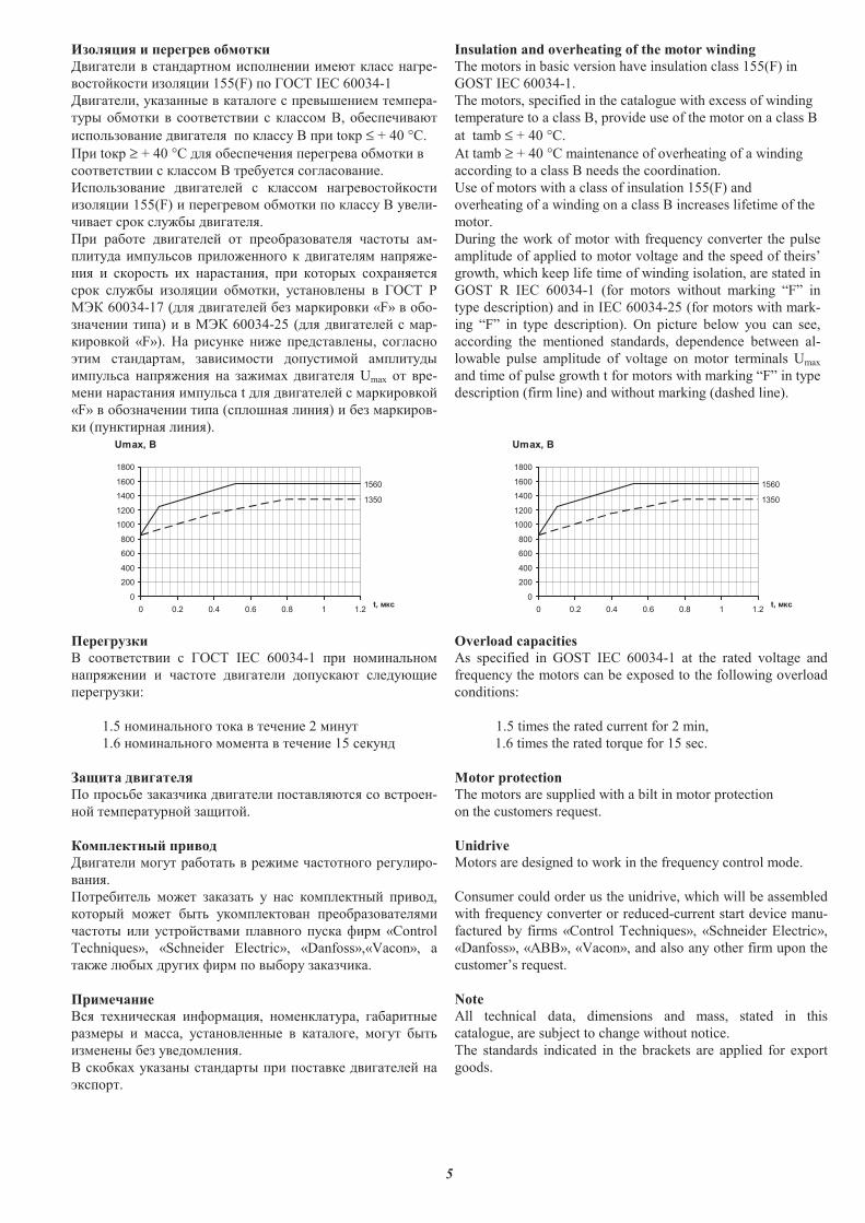
#������� � ��� � �����
��������� � ������ � �� ���� ����� ��� ����-
� � �� �� �� ����� 155(F) � ���� IEC 60034-1
���������, ������� � ����� �� ���������� �������-
���� �� ��� � �������� ��� � �, ����������
�� � � ���� ��������� � ���� � ��� t �� ≤ + 40 °�.
!�� t �� ≥ + 40 °� ��� �������� ��������� �� ��� �
�������� ��� � � �������� ��� ����.
"� � � ���� ���������� ��� � ����� � �� ��
�� ����� 155(F) � �������� � �� ��� � ���� � �����-
������ � � ��#�� ���������.
!�� ��� �� ���������� � ��� ���� ������ ��� �� ��-
������� ����� � ���� #� � � ���������� ����#�-
�� � � � � �$ �������, ��� � � ��$ $������
� � ��#�� �� ����� �� ���, ��� ���� � ���� %
&'( 60034-17 (��� ���������� ��� ������ ��� «F» � � -
������ ����) � � &'( 60034-25 (��� ���������� ���-
��� �� � «F»). )� ����� �#� ����������, ���
*��� ��������, ������ �� � ����� � ���������
����� � ����#��� � ��#���$ ��������� Umax � ���-
��� ������� ����� � t ��� ���������� ������ �� �
«F» � � ������ ���� (�� ��� ����) � ��� ������ �-
�� (�������� ����). Umax, �
1560
1350
0
200
400
600
800
1000
1200
1400
1600
1800
0 0.2 0.4 0.6 0.8 1 1.2t, ���
������
� �������� ���� IEC 60034-1 ��� ���� �
����#��� � ��� �� ��������� � ������ �����+��
����������:
1.5 ���� � � �� � ������ 2 ����
1.6 ���� � � ���� � ������ 15 ����
������ ��������
! �� �� ��������� ��������� � �������� ��� �-
� ���������� � ��+�� �.
���������� �����
��������� � ��� ��� ��� � ��#��� ��� � � ������� -
����.
! �������� � #�� ������� � � � �������� ���� �,
� � ��� � #�� ��� �� ������ �� ��� ���� ��������
��� �� ��� ��� ������ ���� � ���� ,��� «Control
Techniques», «Schneider Electric», «Danfoss»,«Vacon», �
���#� ����$ �����$ ,��� � ��� �� ���������.
�������
�� ��$������ �, ������, ���������, ���������
������� � ���, ��� ����� � ����� ��, � ��� ���
������ ��� ���� �����.
� � ���$ ������ ������� ��� � ����� ���������� �
*�� ��.
Insulation and overheating of the motor winding
The motors in basic version have insulation class 155(F) in
GOST IEC 60034-1.
The motors, specified in the catalogue with excess of winding
temperature to a class B, provide use of the motor on a class B
at tamb ≤ + 40 °�.
At tamb ≥ + 40 °� maintenance of overheating of a winding
according to a class B needs the coordination.
Use of motors with a class of insulation 155(F) and
overheating of a winding on a class B increases lifetime of the
motor.
During the work of motor with frequency converter the pulse
amplitude of applied to motor voltage and the speed of theirs�
growth, which keep life time of winding isolation, are stated in
GOST R IEC 60034-1 (for motors without marking �F� in
type description) and in IEC 60034-25 (for motors with mark-
ing �F� in type description). On picture below you can see,
according the mentioned standards, dependence between al-
lowable pulse amplitude of voltage on motor terminals Umax
and time of pulse growth t for motors with marking �F� in type
description (firm line) and without marking (dashed line).
Umax, �
1560
1350
0
200
400
600
800
1000
1200
1400
1600
1800
0 0.2 0.4 0.6 0.8 1 1.2t, ���
Overload capacities
As specified in GOST IEC 60034-1 at the rated voltage and
frequency the motors can be exposed to the following overload
conditions:
1.5 times the rated current for 2 min,
1.6 times the rated torque for 15 sec.
Motor protection
The motors are supplied with a bilt in motor protection
on the customers request.
Unidrive
Motors are designed to work in the frequency control mode.
Consumer could order us the unidrive, which will be assembled
with frequency converter or reduced-current start device manu-
factured by firms «Control Techniques», «Schneider Electric»,
«Danfoss», «ABB», «Vacon», and also any other firm upon the
customer�s request.
Note
All technical data, dimensions and mass, stated in this
catalogue, are subject to change without notice.
The standards indicated in the brackets are applied for export
goods.
6
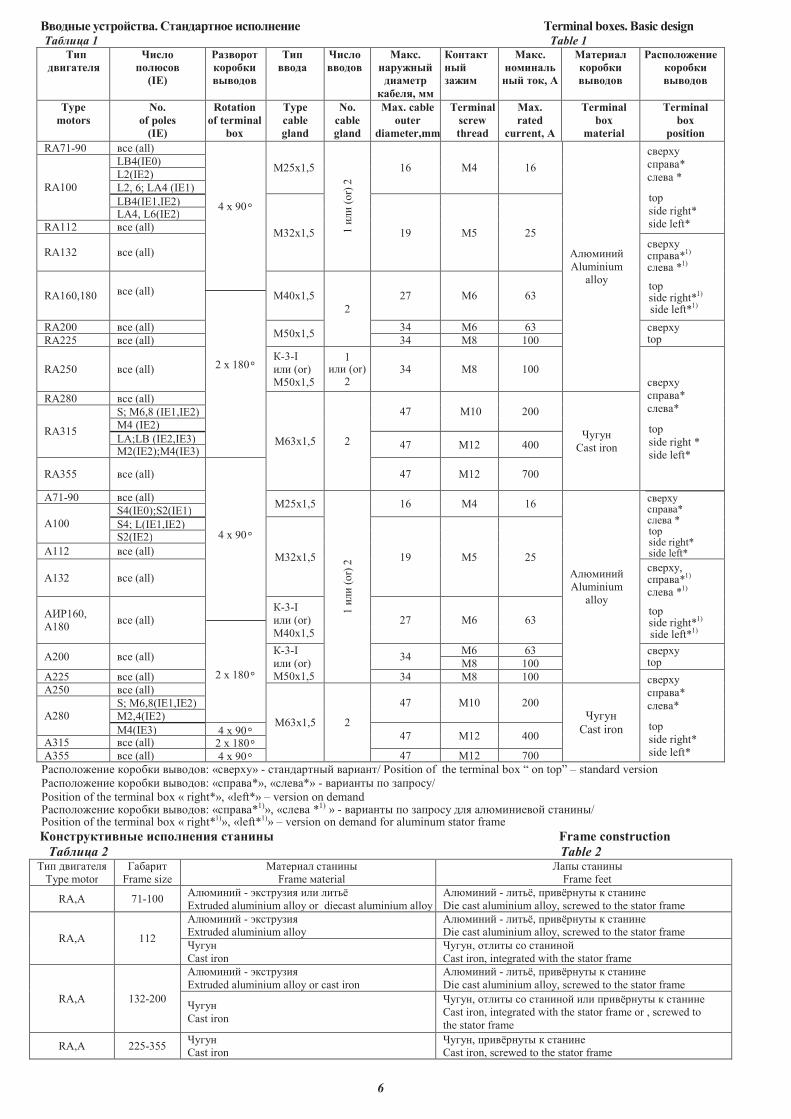
!������ ����� . � �� ���� ��������� Terminal boxes. Basic design ������� 1 Table 1
���
���� ���
����
������
(IE)
� �����
�������
�������
���
����
����
������
# �.
� ������
�� ���
� ����, ��
��� �
���
� ���
# �.
����� ��
��� ��, "
# ��� �
�������
�������
� ���������
�������
�������
Type
motors
No.
of poles
(IE)
Rotation
of terminal
box
Type
cable
gland
No.
cable
gland
Max. cable
outer
diameter,mm
Terminal
screw
thread
Max.
rated
current, "
Terminal
box
material
Terminal
box
position
RA71-90 ��� (all)
4 � 90°
�25�1,5
1 ���
(o
r) 2
16 M4 16
������
Aluminium
alloy
��� ��
�� ���*
����� *
top
side right*
side left*
RA100
LB4(IE0)
L2(IE2)
L2, 6; LA4 (IE1)
LB4(IE1,IE2)
�32�1,5 19 �5 25
L�4, L6(IE2)
RA112 ��� (all)
RA132 ��� (all) ��� ���� ���*
1)
����� *1)
top side right*
1)
side left*1)
RA160,180 ��� (all)
2 � 180°
�40�1,5
2
27 �6 63
RA200 ��� (all)�50�1,5
34 �6 63 ��� ��top RA225 ��� (all) 34 �8 100
RA250 ��� (all)
�-3-I
��� (or)
�50�1,5
1 ��� (or)
2 34 �8 100
��� ��
�� ���*
�����*
top
side right *
side left*
RA280 ��� (all)
�63�1,5 2
47 �10 200
�����
Cast iron
RA315
S; �6,8 (IE1,IE2)
�4 (IE2)
LA;LB (IE2,IE3)47 �12 400
�2(IE2);�4(IE3)
RA355 ��� (all)
4 � 90°
47 �12 700
�71-90 ��� (all)�25�1,5
1 ���
(o
r) 2
16 M4 16
������
Aluminium
alloy
��� ���� ���* ����� * top side right* side left*
�100
S4(IE0);S2(IE1)
S4; L(IE1,IE2)
�32�1,5 19 �5 25
S2(IE2)
�112 ��� (all)
�132 ��� (all) ��� ��, �� ���*
1)
����� *1)
top side right*
1)
side left*1)
���160,
�180 ��� (all)
�-3-I
��� (or)
�40�1,5
27 �6 63
2 � 180°
�200 ��� (all) �-3-I
��� (or)
�50�1,5
34 �6 63 ��� ��
top �8 100
�225 ��� (all) 34 �8 100 ��� ��
�� ���*
�����*
top
side right*
side left*
�250 ��� (all)
�63�1,5 2
47 �10 200
�����
Cast iron
�280 S; �6,8(IE1,IE2)
�2,4(IE2)
�4(IE3) 4 � 90°47 �12 400
�315 ��� (all) 2 � 180°A355 ��� (all) 4 � 90° 47 �12 700
������������ �� ���� �������: «��� ��» - ������ ���� �� ����/ Position of the terminal box � on top� � standard version
������������ �� ���� �������: «�� ���*», «�����*» - �� ����� �� ��� ���/
Position of the terminal box « right*», «left*» � version on demand ������������ �� ���� �������: «�� ���*1)», «����� *1) » - �� ����� �� ��� ��� ��� ��������� �������/ Position of the terminal box « right*1)», «left*1)» � version on demand for aluminum stator frame
����������� ��������� ���� Frame construction
������� 2 Table 2 ��� ���������
Type motor
��� ��
Frame size
���� ��� �������
Frame aterial
!��� �������
Frame feet
RA,A 71-100 A����� - "��� ���� ��� ���#$
%xtruded aluminium alloy or diecast aluminium alloy
������ - ���#$, � ��$ ���� � �������
Die cast aluminium alloy, screwed to the stator frame
RA,� 112
A����� - "��� ����
%xtruded aluminium alloy
������ - ���#$, � ��$ ���� � �������
Die cast aluminium alloy, screwed to the stator frame
�����
&ast iron
�����, ������ �� ��������
&ast iron, integrated with the stator frame
RA,� 132-200
A����� - "��� ����
%xtruded aluminium alloy or cast iron
������ - ���#$, � ��$ ���� � �������
Die cast aluminium alloy, screwed to the stator frame
�����
&ast iron
�����, ������ �� �������� ��� � ��$ ���� � �������
&ast iron, integrated with the stator frame or , screwed to
the stator frame
RA,� 225-355 �����
&ast iron
�����, � ��$ ���� � �������
&ast iron, screwed to the stator frame
7
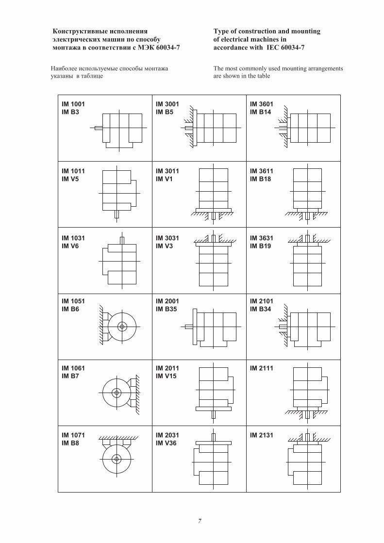
������������ � ������ Type of construction and mounting
����������� ���� � � ����� of electrical machines in
������� �������� � ��� 60034-7 accordance with IEC 60034-7
�������� ������� �� ������ ������ The most commonly used mounting arrangements
������� � ������� are shown in the table
IM 1001
IM B3
IM 3001
IM B5
IM 3601
IM B14
IM 3611
IM B18
IM 3011
IM V1
IM 1011
IM V5
IM 1031
IM V6
IM 3031
IM V3
IM 3631
IM B19
IM 1051
IM B6
IM 2001
IM B35
IM 2101
IM B34
IM 1061
IM B7
IM 2011
IM V15
IM 2111
IM 1071
IM B8
IM 2031
IM V36
IM 2131
8
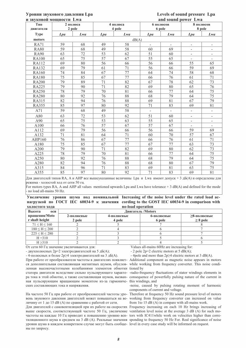
������ ������� ��� ���� Lpa Levels of sound pressure Lpa
� ������� �������� Lwa and sound power Lwa ���
������ �
Type
motors
2 �� ���
2 pole
4 �� ���
4 pole
6 �� ����
6 pole
8 �� ����
8 pole
Lpa Lwa Lpa Lwa Lpa Lwa Lpa Lwa
dB(A)
RA71 59 68 49 58 - - - -RA80 59 68 49 58 60 69 - -
RA90 63 72 53 62 51 60 - -
RA100 65 75 57 67 55 65 - -RA112 69 80 56 66 56 66 55 65
RA132 69 79 61 71 56 66 59 69RA160 74 84 67 77 64 74 58 68
RA180 75 85 67 77 66 76 61 71
RA200 79 89 71 82 67 78 62 73RA225 79 90 71 82 69 80 65 76
RA250 78 79 70 81 66 77 64 75RA280 80 92 76 88 68 79 64 75
RA315 82 94 76 88 69 81 67 79RA355 85 97 80 92 71 83 69 81
A71 59 68 49 58 - - - -
A80 63 72 53 62 51 60 - -
A90 65 75 53 63 55 65 - -
A100 66 76 57 67 57 67 - -A112 69 79 56 66 56 66 59 69
A132 71 81 64 71 60 70 57 67���160 76 86 67 77 66 76 61 71
�180 75 85 67 77 67 77 63 73�200 79 90 71 82 69 80 62 73
�225 78 79 70 81 66 77 64 75
�250 80 92 76 88 68 79 64 75�280 82 94 76 88 68 80 67 79
�315 84 96 71 83 69 81 63 75�355 85 97 80 92 71 83 69 81
��� ���� � � ���� RA, � ��� �� ��� �������� � ���� Lpa Lwa � �� ������ + 3 ��(�) ��� � � �� ���
� ��� - �������� ��� �� � � 50 �.
For motors types RA, � and ��� all values mentioned upwards Lpa and Lwa have tolerance + 3 dB(A) and defined for the mode
- no load all-mains 50 Hz.
��� ������ ������ ���� ��� ������ ����
������� �� ���� IEC 60034-9 ��������
�� ����� ����
Increasing of the noise level under the rated load ac-
cording to the GOST IEC 60034-9 in comparison with
no-load operation
# ���� ���
��������/Moto
r shaft height
!����� � /Motors
2-�� ��� �
2 pole
4-�� ��� �
4 pole
6-�� ��� �
6 pole
"8-�� ��� �
" 8 pole
71 ! 160 2 5 7 8
180 ! 200 2 4 6 7
225 ! 280 2 3 6 7
! =310 2 3 5 6
! "310 2 2 4 5
#� � � 60 $� ���� � �� �������� ���:
- ������������ 2�=2 %� �������� � � �� 5 ��(�);
- 4-�������� &�� 2�"4 %� �������� � � �� 3 ��(�).
Values all-mains 60Hz are increasing for:
- 2 pole 2p=2 electric motors at 5 dB(A);
- 4pole and more than 2p"4 electric motors at 3 dB(A).
'� ��&�� �� �� �&������� �� ������� � ���� ��� ������ �-
�� ������� �(��� ���������)�� ������� �����, �&�����-
� ���� ��������������� ��� &���� %� � ���� �&����
������� ���� �� ��� ���� ��(�� ���(����) � ������ -
�� ���� � %��� �&���� , � ���� ���������)�� �����, ������-
��� ���(����)� ���)��)� ��� ���� �-�� ������ -
��� ���������)� ���� ������ ��.
!� ������ 50 $� �� ��&�� �� �� �&������� � � ������� ���-
� �( �������� ���� �� ���� � � ��� � �������(�� �� � -
���� �� 1 �� 15 dB (A) �� ����� �� � ��&���� �� � �.
��� ���� � � � ����� ����� � �� � ��&�� �� ���������
��� �������, ����� ������) � ������ 50 $�, �� �� �
������� �� ����� 10 $� ������ � ����� �� ������ � �-
��������� ���� � �� �� � �� 3 dB (A). � ��(�� ���� ��
������ ���� � ������ ����� ���� ����� ���� &��( ���&) -
�� �� �������.
Additional component as magnetic noise appears in motors
while working from frequency converter. This noise condi-
tioned by
-radio-frequency fluctuations of stator windings elements in
consequence of powerfully pulsing nature of the current in
this windings, and
-noise, caused by pulsing rotating moment of harmonic
components of current and voltage.
Therefore at frequency 50 Hz sound pressure level of motors
working from frequency converter can increased on value
from 1to 15 dB (A) in compare with all-mains work.
Frequency increasing on each 10 Hz brings increasing of
ventilation level noise at the average 3 dB (A) for such mo-
tors with IC411while work on velocities higher than corre-
sponding to frequency 50 Hz For. Real significance of noise
level in every case study will be informed on request.
9
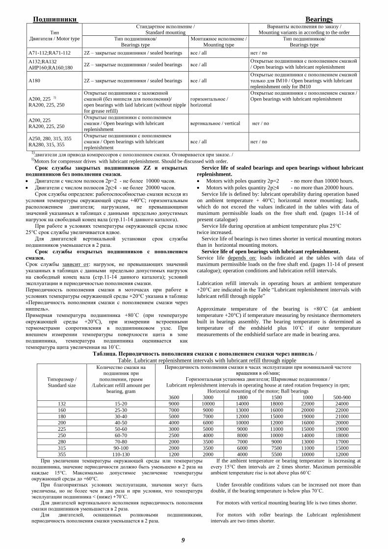
Подшипники Bearings
Тип
Двигателя / Motor type
Стандартное исполнение / Standard mounting
Варианты исполнения по заказу / Mounting variants in according to the order
Тип подшипников/
Bearings type
Монтажное исполнение /
Mounting type
Тип подшипников/
Bearings type
А71-112;RA71-112 2Z – закрытые подшипники / sealed bearings все / all нет / no
А132;RA132
АИР160;RA160;180 2Z – закрытые подшипники / sealed bearings все / all
Открытые подшипники с пополнением смазкой
/ Open bearings with lubricant replenishment
А180 2Z – закрытые подшипники / sealed bearings все / all
Открытые подшипники с пополнением смазкой
только для IM10 / Open bearings with lubricant replenishment only for IM10
А200, 225 1) RA200, 225, 250
Открытые подшипники с заложенной
смазкой (без ниппеля для пополнения)/ open bearings with laid lubricant (without nipple
for grease refill)
горизонтальное / horizontal
Открытые подшипники с пополнением смазки /
Open bearings with lubricant replenishment
А200, 225
RA200, 225, 250
Открытые подшипники с пополнением
смазки / Open bearings with lubricant replenishment
вертикальное / vertical нет / no
А250, 280, 315, 355
RA280, 315, 355
Открытые подшипники с пополнением
смазки / Open bearings with lubricant replenishment
все / all нет / no
1)двигатели для привода компрессоров с пополнением смазки. Оговаривается при заказе. /
1)Motors for compressor drives with lubricant replenishment. Should be discussed with order. Срок службы закрытых подшипников ZZ и открытых
подшипников без пополнения смазки.
Двигатели с числом полюсов 2р=2 - не более 10000 часов.
Двигатели с числом полюсов 2р≥4 - не более 20000 часов.
Срок службы определен: работоспособностью смазки исходя из
условия температуры окружающей среды +40°С; горизонтальным
расположением двигателя; нагрузками, не превышающими
значений указанных в таблицах с данными предельно допустимых
нагрузок на свободный конец вала (стр.11-14 данного каталога).
При работе в условиях температуры окружающей среды плюс
25°С срок службы увеличивается вдвое.
Для двигателей вертикальной установки срок службы
подшипников уменьшается в 2 раза.
Service life of sealed bearings and open bearings without lubricant
replenishment.
Motors with poles quantity 2р=2 - no more than 10000 hours.
Motors with poles quantity 2р≥4 - no more than 20000 hours.
Service life is defined by: lubricant operability during operation based
on ambient temperature + 40°С; horizontal motor mounting; loads,
which do not exceed the values indicated in the tables with data of
maximum permissible loads on the free shaft end. (pages 11-14 of
present catalogue)
Service life during operation at ambient temperature plus 25°С
twice increased.
Service life of bearings is two times shorter in vertical mounting motors
than in horizontal mounting motors.
Срок службы открытых подшипников с пополнением
смазки.
Срок службы зависит от: нагрузок, не превышающих значений
указанных в таблицах с данными предельно допустимых нагрузок
на свободный конец вала (стр.11-14 данного каталога); условий
эксплуатации и периодичностью пополнения смазки.
Периодичность пополнения смазки в моточасах при работе в
условиях температуры окружающей среды +20°С указана в таблице «Периодичность пополнения смазки с пополнением смазки через
ниппель».
Примерная температура подшипника +80˚С (при температуре
окружающей среды +20°С), при измерении встроенными
термометрами сопротивления в подшипниковом узле. При
внешнем измерении температуры поверхности щита в зоне
подшипника, температура подшипника оценивается как
температура щита увеличенная на 10˚С.
Service life of open bearings with lubricant replenishment.
Service life depends on: loads indicated at the tables with data of
maximum permissible loads on the free shaft end. (pages 11-14 of present
catalogue); operation conditions and lubrication refill intervals.
Lubrication refill intervals in operating hours at ambient temperature
+20°С are indicated in the Table “Lubricant replenishment intervals with
lubricant refill through nipple”
Approximate temperature of the bearing is +80˚С (at ambient
temperature +20°С) if temperature measuring by resistance thermometers
built in bearings assembly. The bearing temperature is determined as
temperature of the endshield plus 10˚С if outer temperature
measurements of the endshield surface are made in bearing area.
Таблица. Периодичность пополнения смазки с пополнением смазки через ниппель /
Table. Lubricant replenishment intervals with lubricant refill through nipple
Типоразмер /
Standard size
Количество смазки на подшипник при
пополнении, грамм
/Lubricant refill amount per bearing, gram
Периодичность пополнения смазки в часах эксплуатации при номинальной частоте вращения в об/мин;
Горизонтальная установка двигателя; Шариковые подшипники /
Lubricant replenishment intervals in operating house at rated rotation frequency in rpm; Horizontal mounting of the motor; Ball bearings
3600 3000 1800 1500 1000 500-900
132 15-20 9000 10000 14000 18000 22000 24000
160 25-30 7000 9000 13000 16000 20000 22000
180 30-40 5000 7000 12000 15000 19000 21000
200 40-50 4000 6000 10000 12000 16000 20000
225 50-60 3000 5000 9000 11000 15000 19000
250 60-70 2500 4000 8000 10000 14000 18000
280 70-80 2000 3500 7000 9000 13000 17000
315 90-100 2000 3500 6000 7500 11000 15000
355 110-130 1200 2000 4000 5500 10000 12000
При увеличении температуры окружающей среды или температуры
подшипника, значение периодичности должно быть уменьшено в 2 раза на
каждые 15°С. Максимально допустимое увеличение температуры окружающей среды до +60°С.
При благоприятных условиях эксплуатации, значения могут быть
увеличены, но не более чем в два раза и при условии, что температура эксплуатации подшипника < (ниже) +70˚С.
Для двигателей вертикального исполнения периодичность пополнения
смазки подшипников уменьшается в 2 раза. Для двигателей, оснащенных роликовыми подшипниками,
периодичность пополнения смазки уменьшается в 2 раза.
If the ambient temperature or bearing temperature is increasing at
every 15°С then intervals are 2 times shorter. Maximum permissible
ambient temperature rise is not above plus 60˚С
Under favorable conditions values can be increased not more than
double, if the bearing temperature is below plus 70˚С.
For motors with vertical mounting bearing life is two times shorter.
For motors with roller bearings the Lubricant replenishment
intervals are two times shorter.
10
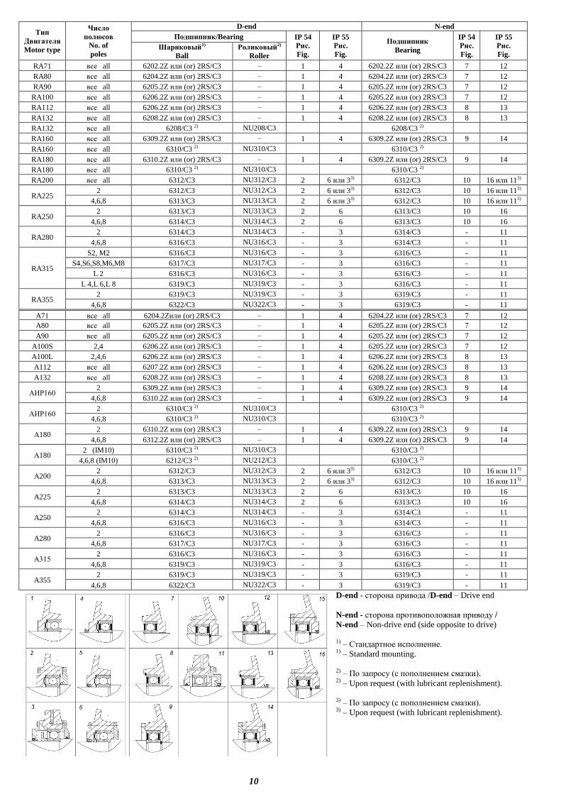
Тип
Двигателя
Motor type
Число
полюсов
No. of
poles
D-end N-end
Подшипник/Bearing IP 54
Рис.
Fig.
IP 55
Рис.
Fig.
Подшипник
Bearing
IP 54
Рис.
Fig.
IP 55
Рис.
Fig. Шариковый1)
Ball
Роликовый2)
Roller
RA71 все all 6202.2Z или (or) 2RS/C3 – 1 4 6202.2Z или (or) 2RS/C3 7 12
RA80 все all 6204.2Z или (or) 2RS/C3 – 1 4 6204.2Z или (or) 2RS/C3 7 12
RA90 все all 6205.2Z или (or) 2RS/C3 – 1 4 6205.2Z или (or) 2RS/C3 7 12
RA100 все all 6206.2Z или (or) 2RS/C3 – 1 4 6205.2Z или (or) 2RS/C3 7 12
RA112 все all 6206.2Z или (or) 2RS/C3 – 1 4 6206.2Z или (or) 2RS/C3 8 13
RA132 все all 6208.2Z или (or) 2RS/C3 – 1 4 6208.2Z или (or) 2RS/C3 8 13
RA132 все all 6208/C3 2) NU208/C3 6208/C3 2)
RA160 все all 6309.2Z или (or) 2RS/C3 – 1 4 6309.2Z или (or) 2RS/C3 9 14
RA160 все all 6310/C3 2) NU310/C3 6310/C3 2)
RA180 все all 6310.2Z или (or) 2RS/C3 – 1 4 6309.2Z или (or) 2RS/C3 9 14
RA180 все all 6310/C3 2) NU310/C3 6310/C3 2)
RA200 все all 6312/C3 NU312/C3 2 6 или 33) 6312/C3 10 16 или 113)
RA225 2 6312/C3 NU312/C3 2 6 или 33) 6312/C3 10 16 или 113)
4,6,8 6313/C3 NU313/C3 2 6 или 33) 6312/C3 10 16 или 113)
RA250 2 6313/C3 NU313/C3 2 6 6313/C3 10 16
4,6,8 6314/C3 NU314/C3 2 6 6313/C3 10 16
RA280 2 6314/C3 NU314/C3 - 3 6314/C3 - 11
4,6,8 6316/C3 NU316/C3 - 3 6314/C3 - 11
RA315
S2, M2 6316/C3 NU316/C3 - 3 6316/C3 - 11
S4,S6,S8,M6,M8 6317/C3 NU317/C3 - 3 6316/C3 - 11
L 2 6316/C3 NU316/C3 - 3 6316/C3 - 11
L 4,L 6,L 8 6319/C3 NU319/C3 - 3 6316/C3 - 11
RA355 2 6319/C3 NU319/C3 - 3 6319/C3 - 11
4,6,8 6322/C3 NU322/C3 - 3 6319/C3 - 11
A71 все all 6204.2Zили (or) 2RS/C3 – 1 4 6204.2Z или (or) 2RS/C3 7 12
A80 все all 6205.2Z или (or) 2RS/C3 – 1 4 6205.2Z или (or) 2RS/C3 7 12
A90 все all 6205.2Z или (or) 2RS/C3 – 1 4 6205.2Z или (or) 2RS/C3 7 12
A100S 2,4 6206.2Z или (or) 2RS/C3 – 1 4 6205.2Z или (or) 2RS/C3 7 12
A100L 2,4,6 6206.2Z или (or) 2RS/C3 – 1 4 6206.2Z или (or) 2RS/C3 8 13
A112 все all 6207.2Z или (or) 2RS/C3 – 1 4 6206.2Z или (or) 2RS/C3 8 13
A132 все all 6208.2Z или (or) 2RS/C3 – 1 4 6208.2Z или (or) 2RS/C3 8 13
АИР160 2 6309.2Z или (or) 2RS/C3 – 1 4 6309.2Z или (or) 2RS/C3 9 14
4,6,8 6310.2Z или (or) 2RS/C3 – 1 4 6309.2Z или (or) 2RS/C3 9 14
АИР160 2 6310/C3 2) NU310/C3 6310/C3 2)
4,6,8 6310/C3 2) NU310/C3 6310/C3 2)
А180 2 6310.2Z или (or) 2RS/C3 – 1 4 6309.2Z или (or) 2RS/C3 9 14
4,6,8 6312.2Z или (or) 2RS/C3 – 1 4 6309.2Z или (or) 2RS/C3 9 14
А180 2 (IM10) 6310/C3 2) NU310/C3 6310/C3 2)
4,6,8 (IM10) 6212/C3 2) NU212/C3 6310/C3 2)
А200 2 6312/C3 NU312/C3 2 6 или 33) 6312/C3 10 16 или 113)
4,6,8 6313/C3 NU313/C3 2 6 или 33) 6312/C3 10 16 или 113)
A225 2 6313/C3 NU313/C3 2 6 6313/C3 10 16
4,6,8 6314/C3 NU314/C3 2 6 6313/C3 10 16
A250 2 6314/C3 NU314/C3 - 3 6314/C3 - 11
4,6,8 6316/C3 NU316/C3 - 3 6314/C3 - 11
A280 2 6316/C3 NU316/C3 - 3 6316/C3 - 11
4,6,8 6317/C3 NU317/C3 - 3 6316/C3 - 11
А315 2 6316/C3 NU316/C3 - 3 6316/C3 - 11
4,6,8 6319/C3 NU319/C3 - 3 6316/C3 - 11
A355 2 6319/C3 NU319/C3 - 3 6319/C3 - 11
4,6,8 6322/C3 NU322/C3 - 3 6319/C3 - 11
D-end - сторона привода /D-end – Drive end
N-end - сторона противоположная приводу /
N-end – Non-drive end (side opposite to drive)
1) – Стандартное исполнение.
1) – Standard mounting.
2) – По запросу (с пополнением смазки). 2) – Upon request (with lubricant replenishment).
3) – По запросу (с пополнением смазки). 3) – Upon request (with lubricant replenishment).
11
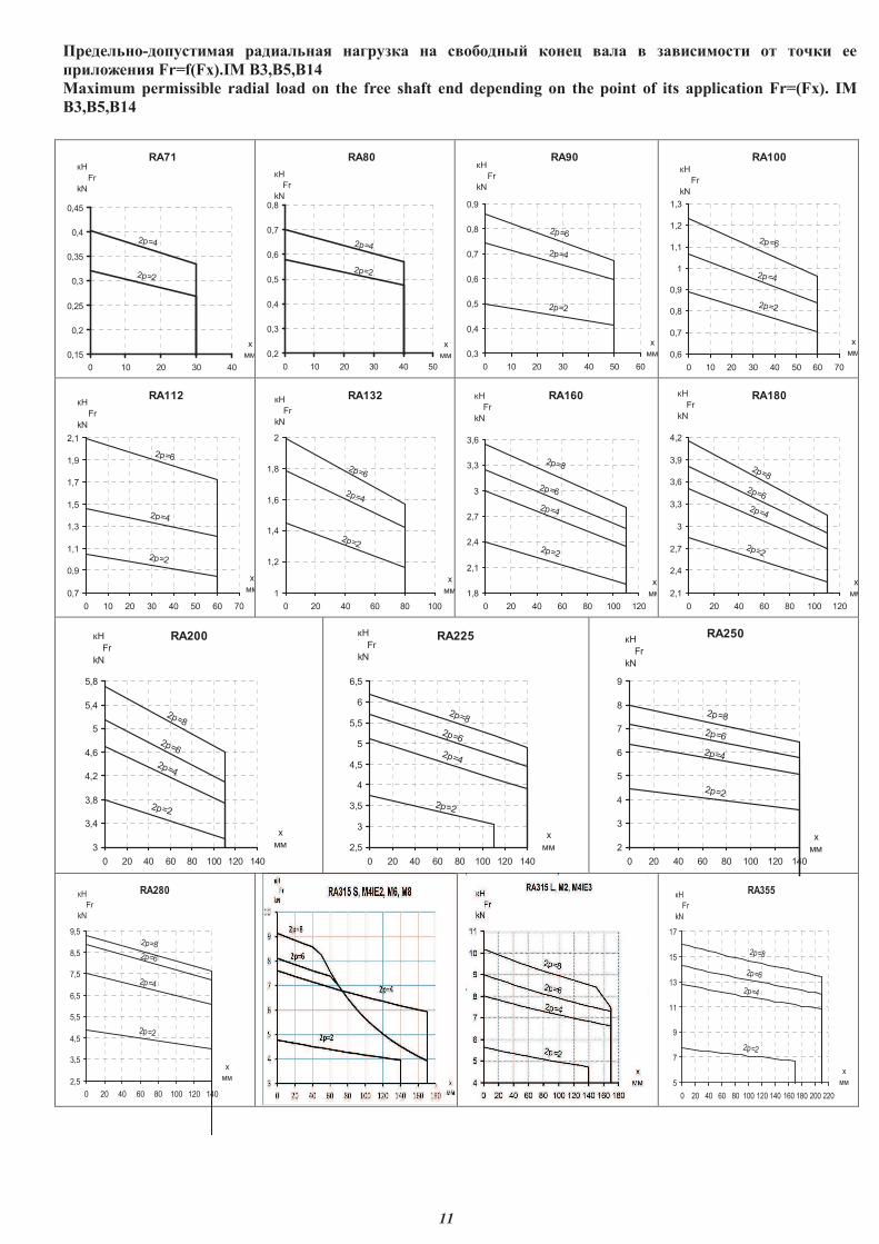
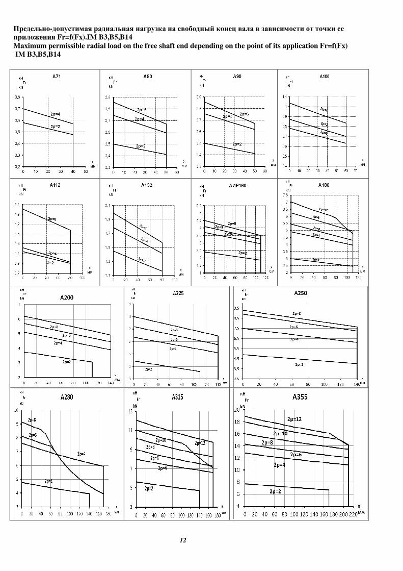
���������-���� ��� ��� ������ ������� �� ��������� ����� ���� � ��� � ���� �� ���� ��
� ����� � Fr=f(Fx).IM B3,B5,B14
Maximum permissible radial load on the free shaft end depending on the point of its application Fr=(Fx). IM
B3,B5,B14
RA71
2p=2
2p=4
0,15
0,2
0,25
0,3
0,35
0,4
0,45
0 10 20 30 40
x
��
��
Fr
kN
RA80
2p=2
2p=4
0,2
0,3
0,4
0,5
0,6
0,7
0,8
0 10 20 30 40 50
x
��
��
Fr
kN
RA90
2p=2
2p=4
2p=6
0,3
0,4
0,5
0,6
0,7
0,8
0,9
0 10 20 30 40 50 60
x
��
��
Fr
kN
RA100
2p=2
2p=4
2p=6
0,6
0,7
0,8
0,9
1
1,1
1,2
1,3
0 10 20 30 40 50 60 70
x
��
��
Fr
kN
RA112
2p=4
2p=2
2p=6
0,7
0,9
1,1
1,3
1,5
1,7
1,9
2,1
0 10 20 30 40 50 60 70
x
��
��
Fr
kN
RA132
2p=2
2p=4
2p=6
1
1,2
1,4
1,6
1,8
2
0 20 40 60 80 100
x
��
��
Fr
kN
RA160
2p=2
2p=4
2p=6
2p=8
1,8
2,1
2,4
2,7
3
3,3
3,6
0 20 40 60 80 100 120
x
��
��
Fr
kN
RA180
2p=2
2p=4
2p=6
2p=8
2,1
2,4
2,7
3
3,3
3,6
3,9
4,2
0 20 40 60 80 100 120
x
��
��
Fr
kN
RA200
2p=2
2p=4
2p=6
2p=8
3
3,4
3,8
4,2
4,6
5
5,4
5,8
0 20 40 60 80 100 120 140
x
��
��
Fr
kN
RA225
2p=2
2p=4
2p=6
2p=8
2,5
3
3,5
4
4,5
5
5,5
6
6,5
0 20 40 60 80 100 120 140
x
��
��
Fr
kN
RA250
2p=2
2p=4
2p=6
2p=8
2
3
4
5
6
7
8
9
0 20 40 60 80 100 120 140
x
��
��
Fr
kN
RA280
2p=2
2p=4
2p=6
2p=8
2,5
3,5
4,5
5,5
6,5
7,5
8,5
9,5
0 20 40 60 80 100 120 140
x
��
��
Fr
kN
RA355
2p=2
2p=4
2p=6
2p=8
5
7
9
11
13
15
17
0 20 40 60 80 100 120 140 160 180 200 220
x
��
��
Fr
kN
���������-���� ��� ��� ������ ������� �� ��������� ����� ���� � ��� � ���� �� ���� ��
� ����� � Fr=f(Fx).IM B3,B5,B14
Maximum permissible radial load on the free shaft end depending on the point of its application Fr=f(Fx)
IM B3,B5,B14
12
13
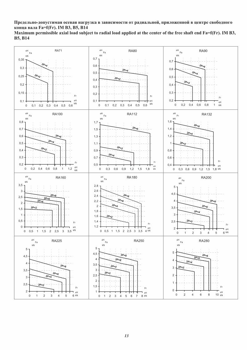
���������-���� ��� ������ ������� � ��� � ���� �� ��� ������, � �������� � ������ ����������
����� ���� Fa=f(Fr). IM B3, B5, B14
Maximum permissible axial load subject to radial load applied at the center of the free shaft end Fa=f(Fr). IM B3,
B5, B14
RA71
��
Fa
kN
2P=2
2P=4
0,1
0,15
0,2
0,25
0,3
0,35
0 0,1 0,2 0,3 0,4 0,5 0,6
Fr
��
kN
RA80
2P=2
2P=4
��
Fa
kN
0,1
0,2
0,3
0,4
0,5
0,6
0,7
0 0,1 0,2 0,3 0,4 0,5 0,6
Fr
��
kN
RA90
2P=2
2P=4
2P=6
��
Fa
kN
0,2
0,3
0,4
0,5
0,6
0,7
0 0,2 0,4 0,6 0,8 1
Fr
��
kN
RA100
2P=2
2P=4
2P=6
��
Fa
kN
0,2
0,3
0,4
0,5
0,6
0,7
0,8
0 0,2 0,4 0,6 0,8 1 1,2
Fr
��
kN
RA112
2P=2
2P=4
2P=6
��
Fa
kN
0,5
0,7
0,9
1,1
1,3
1,5
1,7
0 0,3 0,6 0,9 1,2 1,5 1,8
Fr
��
kN
RA132
2P=2
��
Fr
kN
2P=4
2P=6
0,4
0,6
0,8
1
1,2
1,4
1,6
0 0,3 0,6 0,9 1,2 1,5 1,8
Fr
��
kN
RA160
2P=2
��
Fa
kN
2P=4
2P=6
2P=8
0
0,5
1
1,5
2
2,5
3
3,5
0 0,5 1 1,5 2 2,5 3 3,5
Fr
��
kN
RA180
2P=2
��Fa
kN
2P=4
2P=6
2P=8
1,2
1,4
1,6
1,8
2
2,2
2,4
2,6
2,8
0 0,5 1 1,5 2 2,5 3 3,5 4
Fr
��
kN
RA200
2P=2
�� Fa
kN
2P=4
2P=6
2P=8
2
2,5
3
3,5
4
4,5
5
0 1 2 3 4 5 6
Fr
��
kN
RA225
2P=2
��Fa
kN
2P=4
2P=6
2P=8
2
2,5
3
3,5
4
4,5
5
0 1 2 3 4 5 6
Fr
��
kN
RA250
2P=2
2P=4
2P=6
2P=8
1
1,5
2
2,5
3
3,5
4
4,5
5
0 1 2 3 4 5 6 7 8
Fr
��
kN
��Fa
kN
RA280
2P=2
��Fa
kN
2P=4
2P=6
2P=8
0
1
2
3
4
5
0 2 4 6 8 10
Fr
��
kN
14
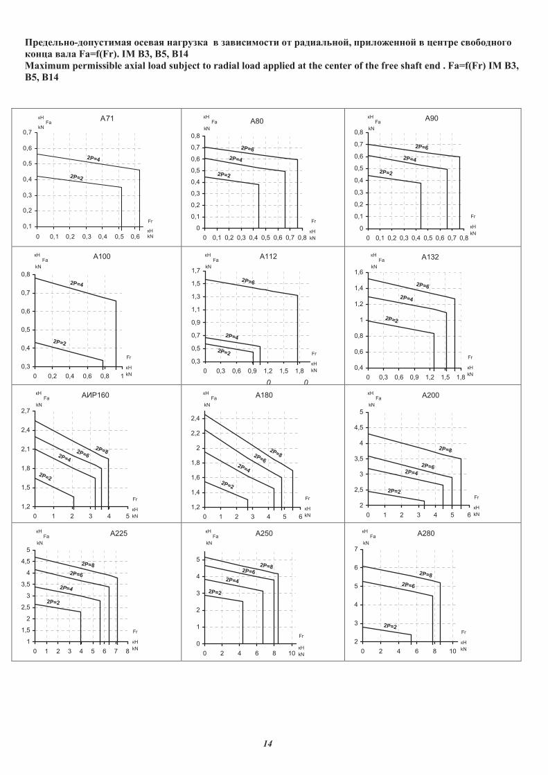
���������-���� ��� ������ ������� � ��� � ���� �� ��� ������, � �������� � ������ ����������
����� ���� Fa=f(Fr). IM B3, B5, B14
Maximum permissible axial load subject to radial load applied at the center of the free shaft end . Fa=f(Fr) IM B3,
B5, B14
A71
2P=2
2P=4
��Fa
kN
0,1
0,2
0,3
0,4
0,5
0,6
0,7
0 0,1 0,2 0,3 0,4 0,5 0,6
Fr
��
kN
A80
2P=2
2P=4
2P=6
0
0,1
0,2
0,3
0,4
0,5
0,6
0,7
0,8
0 0,1 0,2 0,3 0,4 0,5 0,6 0,7 0,8
Fr
��
kN
��Fa
kN
A90 ��Fa
kN
2P=2
2P=4
2P=6
0
0,1
0,2
0,3
0,4
0,5
0,6
0,7
0,8
0 0,1 0,2 0,3 0,4 0,5 0,6 0,7 0,8
Fr
��
kN
A100 ��Fa
kN
2P=2
2P=4
0,3
0,4
0,5
0,6
0,7
0,8
0 0,2 0,4 0,6 0,8 1
Fr
��
kN
A112
0
��Fa
kN
0
2P=2
2P=4
2P=6
0,3
0,5
0,7
0,9
1,1
1,3
1,5
1,7
0 0,3 0,6 0,9 1,2 1,5 1,8
Fr
��
kN
A132 ��Fa
kN
2P=2
2P=4
2P=6
0,4
0,6
0,8
1
1,2
1,4
1,6
0 0,3 0,6 0,9 1,2 1,5 1,8
Fr
��
kN
���160
2P=2
��Fa
kN
2P=4
2P=6
2P=8
1,2
1,5
1,8
2,1
2,4
2,7
0 1 2 3 4 5
Fr
��
kN
A180 ��Fa
kN
2P=2
2P=4
2P=6
2P=8
1,2
1,4
1,6
1,8
2
2,2
2,4
0 1 2 3 4 5 6
Fr
��
kN
A200
2P=2
��Fa
kN
2P=4
2P=6
2P=8
2
2,5
3
3,5
4
4,5
5
0 1 2 3 4 5 6
Fr
��
kN
A225
2P=2
2P=4
2P=6
2P=8
1
1,5
2
2,5
3
3,5
4
4,5
5
0 1 2 3 4 5 6 7 8
Fr
��
kN
��Fa
kN
A250
2P=2
��Fa
kN
2P=4
2P=6
2P=8
0
1
2
3
4
5
0 2 4 6 8 10
Fr
��
kN
A280
2P=2
��Fa
kN
2P=6
2P=8
2
3
4
5
6
7
0 2 4 6 8 10
Fr
��
kN
15
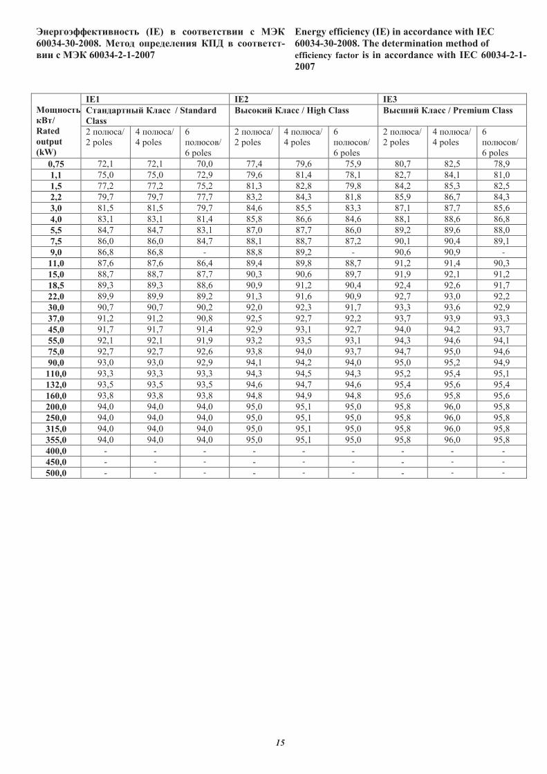
�������������� � (IE) � ���� ��� ���
60034-30-2008. ���� ����������� ��� � ���� -
��� ��� 60034-2-1-2007
Energy efficiency (IE) in accordance with IEC
60034-30-2008. The determination method of
efficiency factor is in accordance with IEC 60034-2-1-
2007
����� �
#/
Rated
output
(kW)
IE1 IE2 IE3
��������� ��� / Standard
Class
#� ��� ��� / High Class #� ��� ��� / Premium Class
2 ������/
2 poles
4 ������/
4 poles
6
�������/
6 poles
2 ������/
2 poles
4 ������/
4 poles
6
�������/
6 poles
2 ������/
2 poles
4 ������/
4 poles
6
�������/
6 poles
0,75 72,1 72,1 70,0 77,4 79,6 75,9 80,7 82,5 78,9
1,1 75,0 75,0 72,9 79,6 81,4 78,1 82,7 84,1 81,0
1,5 77,2 77,2 75,2 81,3 82,8 79,8 84,2 85,3 82,5
2,2 79,7 79,7 77,7 83,2 84,3 81,8 85,9 86,7 84,3
3,0 81,5 81,5 79,7 84,6 85,5 83,3 87,1 87,7 85,6
4,0 83,1 83,1 81,4 85,8 86,6 84,6 88,1 88,6 86,8
5,5 84,7 84,7 83,1 87,0 87,7 86,0 89,2 89,6 88,0
7,5 86,0 86,0 84,7 88,1 88,7 87,2 90,1 90,4 89,1
9,0 86,8 86,8 - 88,8 89,2 - 90,6 90,9 -
11,0 87,6 87,6 86,4 89,4 89,8 88,7 91,2 91,4 90,3
15,0 88,7 88,7 87,7 90,3 90,6 89,7 91,9 92,1 91,2
18,5 89,3 89,3 88,6 90,9 91,2 90,4 92,4 92,6 91,7
22,0 89,9 89,9 89,2 91,3 91,6 90,9 92,7 93,0 92,2
30,0 90,7 90,7 90,2 92,0 92,3 91,7 93,3 93,6 92,9
37,0 91,2 91,2 90,8 92,5 92,7 92,2 93,7 93,9 93,3
45,0 91,7 91,7 91,4 92,9 93,1 92,7 94,0 94,2 93,7
55,0 92,1 92,1 91,9 93,2 93,5 93,1 94,3 94,6 94,1
75,0 92,7 92,7 92,6 93,8 94,0 93,7 94,7 95,0 94,6
90,0 93,0 93,0 92,9 94,1 94,2 94,0 95,0 95,2 94,9
110,0 93,3 93,3 93,3 94,3 94,5 94,3 95,2 95,4 95,1
132,0 93,5 93,5 93,5 94,6 94,7 94,6 95,4 95,6 95,4
160,0 93,8 93,8 93,8 94,8 94,9 94,8 95,6 95,8 95,6
200,0 94,0 94,0 94,0 95,0 95,1 95,0 95,8 96,0 95,8
250,0 94,0 94,0 94,0 95,0 95,1 95,0 95,8 96,0 95,8
315,0 94,0 94,0 94,0 95,0 95,1 95,0 95,8 96,0 95,8
355,0 94,0 94,0 94,0 95,0 95,1 95,0 95,8 96,0 95,8
400,0 - - - - - - - - -
450,0 - - - - - - - - -
500,0 - - - - - - - - -
16
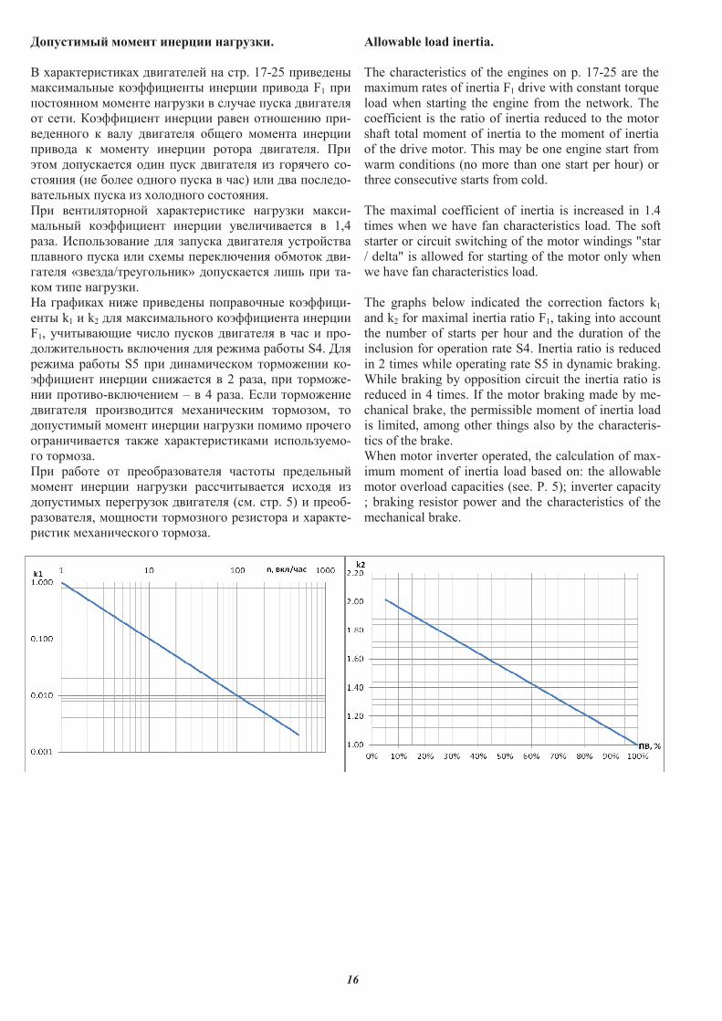
�������� ������ ��� ��� ��� ����.
� �������������� ������ �� �� ��. 17-25 ��������
������ ���� ������������ ������� ������ F1 ���
��������� ������� �������� � ���� ���� ������ �
�� ���. ����������� ������� ����� ��������� ���-
�������� � �� � ������ � �� ��� ������� �������
������ � ������� ������� ������ ������ �. !��
���� �������� ��� ��� ������ � �� �������� �-
������ (�� �� �� ����� ���� � ��) � � �� �� ��-
���� ���� ���� �� �� ����� �������.
!�� ����� ������� ������������� �������� ����-
�� ���� ����������� ������� ��� �������� � 1,4
����. "�� �������� � ������ ������ � ��������
� ������ ���� � � ���� ����� ������ ������� ��-
���� � «�����/������ ����» �������� ��� ��� ��-
��� ���� ��������.
#� �������� ��$� �������� ����������� ��������-
���� k1 � k2 � ������ ����� ������������ �������
F1, �������� �� �� � ����� ������ � � �� � ���-
� $��� ����� �� ������ � ��$��� ������ S4. % �
��$��� ������ S5 ��� ���������� �����$���� ��-
��������� ������� ��$���� � 2 ����, ��� �����$�-
��� �������-�� ������� � � 4 ����. & � �����$����
������ � ���������� ����������� ��������, ��
�������� ������ ������� �������� ������ �������
������������� ���$� ��������������� ��� ������-
�� �������.
!�� ������ �� ������������� � ������ ���� ����
������ ������� �������� ����������� ���� ��
�������� ���������� ������ � (�. ��. 5) � �����-
�������� �, �� ���� ���������� �������� � �������-
����� ������������ �������.
Allowable load inertia.
The characteristics of the engines on p. 17-25 are the
maximum rates of inertia F1 drive with constant torque
load when starting the engine from the network. The
coefficient is the ratio of inertia reduced to the motor
shaft total moment of inertia to the moment of inertia
of the drive motor. This may be one engine start from
warm conditions (no more than one start per hour) or
three consecutive starts from cold.
The maximal coefficient of inertia is increased in 1.4
times when we have fan characteristics load. The soft
starter or circuit switching of the motor windings "star
/ delta" is allowed for starting of the motor only when
we have fan characteristics load.
The graphs below indicated the correction factors k1
and k2 for maximal inertia ratio F1, taking into account
the number of starts per hour and the duration of the
inclusion for operation rate S4. Inertia ratio is reduced
in 2 times while operating rate S5 in dynamic braking.
While braking by opposition circuit the inertia ratio is
reduced in 4 times. If the motor braking made by me-
chanical brake, the permissible moment of inertia load
is limited, among other things also by the characteris-
tics of the brake.
When motor inverter operated, the calculation of max-
imum moment of inertia load based on: the allowable
motor overload capacities (see. P. 5); inverter capacity
; braking resistor power and the characteristics of the
mechanical brake.
17
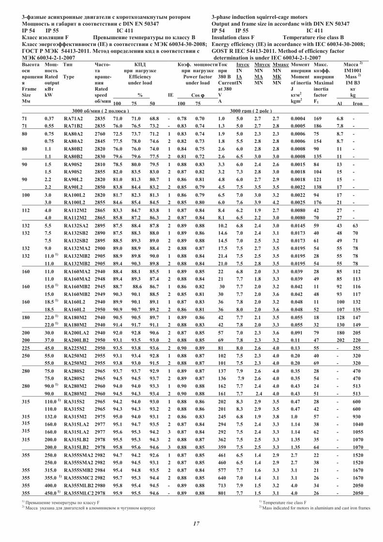
3-������ ��������� � ������� � ��������������� ����� 3-phase induction squirrel-cage motors
�������� � ������ ���� ���� �� � DIN EN 50347 Output and frame size in accordanc with DIN EN 50347
IP 54 IP 55 IC 411 IP 54 IP 55 IC 411
����� �������� F �� ������ ��������� �� ������ � Insulation class F Temperature rise class B
����� ������������ ����� (IE) ���� ���� �� � � � 60034-30-2008; Energy efficiency (IE) in accordance with IEC 60034-30-2008;
!"#$ % � � 54413-2011. ����� ���������� ��� ���� ���� �� � GOS$ R IEC 54413-2011. Method of efficiency factor
� � 60034-2-1-2007 determination is under IEC 60034-2-1-2007
������
���
�����
�
Frame
Size
��
mm
���-
�����
Rated
output
���
kW
$��
Type
&����-
��
���-
���
Rated
speed
��/���
rpm
��'
�� �������
Efficiency
under load
% IE
����. ��������
�� �������
Power factor
under load
Cos ϕϕϕϕ
$��
��
380 �
Current
at 380
V
(
I����
IN
IA
IN
M����
MN
MA
MN
M����
MN
M�
MN
������
������
Moment
of inertia
J
���2
kgm2
����.
�����.
������
Maximal
inertia
factor
F1
����� 2)
IM1001
Mass 2)
IM B3
��
kg
100 75 50 100 75 Al Iron
3000 ��/��� ( 2 ���)�� ) 3000 rpm ( 2 pole )
71 0.37 RA71A2 2835 71.0 71.0 68.8 - 0.78 0.70 1.0 5.0 2.7 2.7 0.0004 169 6.8 -
71 0.55 RA71B2 2835 76.0 76.5 73.2 - 0.83 0.74 1.3 5.0 2.7 2.8 0.0005 186 7.8 -
80 0.75 RA80A2 2760 72.5 73.7 71.2 1 0.83 0.74 1.9 5.0 2.3 2.3 0.0006 75 8.7 -
0.75 RA80A2 2845 77.5 78.0 74.6 2 0.82 0.73 1.8 5.5 2.8 2.8 0.0006 154 8.7 -
80 1.1 RA80B2 2820 76.0 76.0 74.0 1 0.84 0.75 2.6 6.0 2.8 2.8 0.0008 90 11 -
1.1 RA80B2 2830 79.6 79.6 77.5 2 0.81 0.72 2.6 6.5 3.0 3.0 0.0008 135 11 -
90 1.5 RA90S2 2810 78.5 80.0 79.5 1 0.88 0.83 3.3 6.0 2.4 2.6 0.0015 84 13 -
1.5 RA90S2 2855 82.0 83.5 83.0 2 0.87 0.82 3.2 7.3 2.8 3.0 0.0018 104 15 -
90 2.2 RA90L2 2820 81.0 81.3 80.7 1 0.86 0.81 4.8 6.0 2.7 2.9 0.0018 121 15 -
2.2 RA90L2 2850 83.8 84.4 83.2 2 0.85 0.79 4.5 7.5 3.5 3.5 0.0022 138 17 -
100 3.0 RA100L2 2820 81.7 82.3 81.3 1 0.86 0.79 6.5 7.0 3.0 3.2 0.0022 94 17 -
3.0 RA100L2 2855 84.6 85.4 84.5 2 0.85 0.80 6.0 7.6 3.9 4.2 0.0025 176 21 -
112 4.0 RA112M2 2865 83.3 84.7 83.8 1 0.87 0.84 8.4 6.2 1.9 2.7 0.0080 42 27 -
4.0 RA112M2 2865 85.8 87.2 86.3 2 0.87 0.84 8.1 6.5 2.2 3.0 0.0080 70 27 -
132 5.5 RA132SA2 2895 87.5 88.4 87.8 2 0.89 0.88 10.2 6.8 2.4 3.0 0.0145 59 43 63
132 7.5 RA132SB2 2890 87.5 88.3 88.0 1 0.89 0.86 14.6 7.0 2.4 3.1 0.0173 40 48 70
7.5 RA132SB2 2895 88.5 89.3 89.0 2 0.89 0.88 14.5 7.0 2.5 3.2 0.0173 61 49 71
132 9.0 RA132MA2 2900 89.0 88.9 88.4 2 0.88 0.87 17.5 7.5 2.7 3.5 0.0195 54 55 78
132 11.0 1) RA132��2 2905 88.9 89.8 90.0 1 0.88 0.84 21.4 7.5 2.5 3.5 0.0195 28 55 78
11.0 RA132M�2 2905 89.4 90.3 89.8 2 0.88 0.84 21.0 7.5 2.8 3.5 0.0195 54 55 78
160 11.0 RA160MA2 2940 88.4 88.1 85.5 1 0.89 0.85 22 6.8 2.0 3.3 0.039 28 85 112
11.0 RA160MA2 2948 89.4 89.3 87.4 2 0.88 0.84 21 7.7 1.8 3.3 0.039 49 85 113
160 15.0 1) RA160MB2 2945 88.7 88.6 86.7 1 0.86 0.82 30 7.7 2.0 3.2 0.042 11 92 116
15.0 RA160MB2 2949 90.3 90.1 88.5 2 0.85 0.81 30 7.7 2.0 3.6 0.042 48 93 117
160 18.5 1) RA160L2 2940 89.9 90.1 89.1 1 0.87 0.83 36 7.8 2.0 3.2 0.048 11 100 132
18.5 RA160L2 2950 90.9 90.7 89.2 2 0.86 0.81 36 8.0 2.0 3.6 0.048 52 107 135
180 22.0 1) RA180M2 2940 90.5 90.5 89.7 1 0.89 0.86 42 7.7 2.1 3.5 0.055 18 128 147
22.0 1) RA180M2 2940 91.4 91.7 91.1 2 0.88 0.83 42 7.8 2.0 3.3 0.055 32 130 149
200 30.0 RA200LA2 2940 92.0 92.8 90.6 2 0.87 0.85 57 7.0 2.3 3.6 0.091 79 180 205
200 37.0 RA200LB2 2950 93.1 93.5 93.0 2 0.88 0.85 69 7.8 2.3 3.2 0.11 47 202 220
225 45.0 RA225M2 2950 93.5 93.8 93.6 2 0.90 0.89 81 8.0 2.6 4.0 0.13 55 - 255
250 55.0 RA250M2 2955 93.1 93.4 92.8 1 0.88 0.87 102 7.5 2.3 4.0 0.20 40 - 320
55.0 RA250M2 2955 93.8 93.0 91.5 2 0.88 0.87 101 7.5 2.3 4.0 0.20 69 - 320
280 75.0 RA280S2 2965 93.7 93.7 92.9 1 0.89 0.87 137 7.9 2.6 4.0 0.35 28 - 470
75.0 RA280S2 2965 94.5 94.5 93.7 2 0.89 0.87 136 7.9 2.6 4.0 0.35 54 - 470
280 90.0 1) RA280M2 2960 94.0 94.0 93.3 1 0.90 0.88 162 7.7 2.4 4.0 0.43 24 - 513
90.0 RA280M2 2960 94.5 94.3 93.4 2 0.90 0.88 161 7.7 2.4 4.0 0.43 51 - 513
315 110.0 1) RA315S2 2965 94.2 94.0 93.0 1 0.88 0.86 202 8.3 2.9 3.5 0.47 28 - 600
110.0 RA315S2 2965 94.3 94.3 93.2 2 0.88 0.86 201 8.3 2.9 3.5 0.47 42 - 600
315 132.0 RA315M2 2975 95.0 94.0 93.1 2 0.86 0.83 245 6.8 1.9 3.8 1.0 57 - 930
315 160.0 RA315LA2 2977 95.1 94.7 93.5 2 0.87 0.84 294 7.5 2.4 3.3 1.14 38 - 1040
315 160.0 RA315LA2 2977 95.6 95.3 94.2 3 0.87 0.84 292 7.5 2.4 3.3 1.14 62 - 1055
315 200.0 RA315LB2 2978 95.5 95.3 94.3 2 0.88 0.87 362 7.5 2.5 3.3 1.35 35 - 1070
200.0 RA315LB2 2978 95.8 95.6 94.6 3 0.88 0.85 359 7.5 2.5 3.3 1.35 64 - 1070
355 250.0 RA355S�(2 2982 94.7 94.2 92.6 1 0.87 0.85 461 6.5 1.4 2.9 2.7 22 - 1520
250.0 RA355S�(2 2982 95.0 94.5 93.1 2 0.87 0.85 460 6.5 1.4 2.9 2.7 38 - 1520
355 315.0 RA355S�B2 2984 95.4 94.8 93.5 2 0.87 0.84 577 7.7 1.6 3.3 3.1 21 - 1670
355 355.0 1) RA355S�C2 2982 95.7 95.3 94.4 2 0.88 0.85 640 7.0 1.4 3.1 3.1 26 - 1670
355 400.0 RA355�LB2 2980 95.8 95.4 94.5 - 0.89 0.88 713 7.9 1.5 3.2 4.0 34 - 2050
355 450.0 1) RA355�LC2 2978 95.9 95.5 94.6 - 0.89 0.88 801 7.7 1.5 3.1 4.0 26 - 2050
1) ���������� ����� �� �� ����� F 1) Temperature rise class F 2) ����� ������ ��� ��������� � ��������� � � � ��� ���� �� 2) Mass indicated for motors in aluminium and cast iron frames
14
1395
1095
18
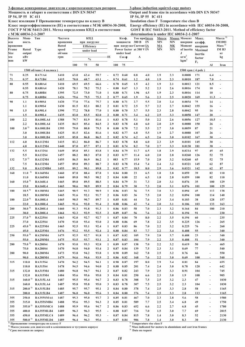
3-������ ��������� � ������� � ��������������� ����� 3-phase induction squirrel-cage motors
�������� � ������ ���� ���� �� � DIN EN 50347 Output and frame size in accordance with DIN EN 50347
IP 54, IP 55 IC 411 IP 54, IP 55 IC 411
����� �������� F �� ������ ��������� �� ������ � Insulation class F Temperature rise class B
����� ������������ ����� (IE) ���� ���� �� � � � 60034-30-2008, Energy efficiency (IE) in accordance with IEC 60034-30-2008,
!"#$ % � � 54413-2011. ����� ���������� ��& ���� ���� �� GOS$ R IEC 54413-2011. Method of efficiency factor
� � � 60034-2-1-2007 determination is under IEC 60034-2-1-2007 ������
���
������
Frame
Size
��
mm
���-
�����
Rated
output
���
kW
$��
Type
'������
������
Rated
speed
��/���
rpm
��&
�� �������
Efficiency
under load
% IE
����.
��������
�� �������
Power factor
under load
Cos ϕϕϕϕ
$�� ��
380 �
Current
at 380 V
(
I����
IN
IA
IN
M����
MN
MA
MN
M����
MN
M�
MN
������
������
Moment
of inertia
J
���2
kgm2
����.
�����.
������
Maximal
inertia
factor
F1
�����2)
IM1001
Mass 2)
IM B3
��
kg
100 75 50 100 75 Al Iron
1500 ��/��� ( 4 ���)�� ) 1500 rpm ( 4 pole )
71 0.25 RA71A4 1410 63.0 62.4 59.7 - 0.72 0.60 0.8 4.0 1.9 2.3 0.0008 171 6.4 -
71 0.37 RA71B4 1415 70.0 68.7 63.1 - 0.74 0.61 1.2 4.0 1.9 2.3 0.0010 187 7.0 -
80 0.55 RA80A4 69.5 69.5 66.6 - 0.78 0.65 1.5 4.2 1.9 2.1 0.0012 121 8.5 -
0.55 RA80A4 1420 78.1 78.2 75.2 - 0.80 0.67 1.3 5.2 2.3 2.6 0.0016 174 10 -
80 0.75 RA80B4 72.5 73.0 71.0 1 0.80 0.71 1.96 4.5 1.9 2.3 0.0016 114 10 -
0.75 RA80B4 1426 79.6 79.5 75.3 2 0.77 0.65 1.9 5.6 2.3 2.5 0.0020 169 11.3 -
90 1.1 RA90S4 1420 77.0 77.6 75.7 1 0.80 0.71 2.7 5.5 2.0 2.4 0.0034 75 14 -
1.1 RA90S4 1430 81.5 82.1 80.2 2 0.81 0.72 2.5 5.7 2.2 2.7 0.0042 155 16 -
90 1.5 RA90L4 1390 77.2 78.8 77.0 1 0.80 0.70 3.7 5.5 2.3 2.8 0.0042 95 16 -
1.5 RA90L4 1435 83.0 83.5 82.0 2 0.80 0.71 3.4 6.2 2.5 3.3 0.0058 147 20 -
100 2.2 RA100LA4 1388 79.7 81.9 81.6 1 0.83 0.78 5.1 5.0 2.2 2.6 0.0056 127 18.5 -
2.2 RA100LA4 1435 84.5 85.4 84.5 2 0.83 0.78 4.8 6.0 2.0 2.9 0.0088 150 26 -
100 3.0 1)
RA100LB4 1395 79.0 80.8 79.3 0 0.80 0.70 7.2 5.5 2.7 3.0 0.0059 87 21 -
3.0 RA100LB4 1425 81.5 82.6 81.6 1 0.82 0.77 6.8 5.5 1.9 2.7 0.0088 107 26 -
3.0 RA100LB4 1435 85.8 86.8 86.5 2 0.82 0.74 6.2 6.5 2.6 3.0 0.0102 167 30 -
112 4.0 RA112M4 1415 83.2 86.0 86.7 1 0.83 0.78 8.8 6.0 2.3 2.9 0.0101 145 30 -
4.0 RA112M4 1440 87.0 87.7 87.1 2 0.81 0.74 8.2 7.0 2.7 3.3 0.0130 181 38 -
132 5.5 RA132S4 1449 85.0 85.1 83.8 1 0.84 0.79 11.7 6.5 1.8 2.9 0.0214 97 45 65
5.5 RA132S4 1457 88.2 88.3 87.0 2 0.83 0.77 11.4 6.0 2.0 2.8 0.0260 126 52 75
132 7.5 1)
RA132M4 1455 86.5 86.9 86.2 1 083 0.77 15.9 7.0 2.8 3.2 0.0260 65 52 75
7.5 RA132M4 1457 89.0 89.3 88.7 2 0.83 0.78 15.4 7.4 2.4 3.2 0.0321 145 62 87
132 9.0 RA132MB4 1455 89.2 90.1 89.8 2 0.82 0.77 18.5 8.0 2.9 3.6 0.0321 142 62 87
160 11.0 1)
RA160M4 1460 87.8 88.4 87.8 1 0.84 0.80 23 6.5 1.8 2.8 0.059 39 82 110
11.0 RA160M4 1460 89.8 90.5 90.2 2 0.84 0.80 22 6.5 1.8 2.8 0.059 100 82 110
160 15.0 1)
RA160L4 1465 89.0 89.5 88.5 1 0.84 0.79 31 7.3 2.0 3.1 0.076 35 100 129
15.0 RA160L4 1465 90.6 90.9 89.9 2 0.84 0.79 30 7.3 2.0 3.1 0.076 101 100 129
180 18.5 1)
RA180M4 1465 90.5 91.2 90.9 1 0.86 0.83 36 7.5 2.0 3.2 0.094 45 112 138
18.5 RA180M4 1465 91.6 92.1 91.7 2 0.86 0.83 36 7.5 2.0 3.2 0.094 100 114 140
180 22.0 1)
RA180L4 1465 90.5 90.7 89.7 1 0.85 0.81 44 7.6 2.3 3.4 0.103 38 128 157
22.0 RA180L4 1465 91.6 92.0 91.4 2 0.88 0.86 42 7.4 2.0 3.1 0.106 103 133 163
200 30.0 1)
RA200L4 1460 91.3 91.8 91.3 1 0.86 0.83 58 7.0 2.3 3.2 0.164 84 180 210
30.0 RA200L4 1464 92.3 92.9 92.5 2 0.89 0.87 56 7.6 2.2 3.2 0.194 91 230
225 37.0 1)
RA225S4 1463 92.0 92.7 92.7 1 0.87 0.84 70 8.0 2.2 3.5 0.194 60 - 235
37.0 RA225S4 1470 93.0 93.4 93.0 2 0.88 0.86 69 7.8 2.2 3.5 0.225 126 - 265
225 45.0 1)
RA225�4 1465 92.5 93.1 92.4 1 0.87 0.83 86 7.0 2.2 3.2 0.225 76 - 260
45.0 RA225M4 1476 93.2 93.5 92.4 2 0.88 0.84 83 7.7 2.2 3.4 0.408 55 - 340
250 55.0 1)
RA250M4 1475 92.5 92.7 91.8 1 0.87 0.82 105 7.9 2.8 3.7 0.408 23 - 340
55.0 RA250M4 1475 93.5 93.7 93.1 2 0.87 0.83 104 7.9 2.2 3.5 0.408 51 - 340
280 75.0 1)
RA280S4 1470 93.0 93.3 92.8 1 0.89 0.87 138 7.0 2.2 3.2 0.619 50 - 465
75.0 RA280S4 1470 94.0 94.0 93.4 2 0.87 0.84 139 7.5 2.3 3.1 0.69 77 540
280 90.0 RA280M4 1473 93.8 94.2 93.8 1 0.90 0.89 162 7.8 2.5 3.2 0.76 66 - 550
90.0 RA280M4 1479 94.6 94.6 93.9 2 0.86 0.82 168 7.6 2.2 3.0 0.69 100 - 540
315 110.0 RA315S4 1470 94.2 94.5 94.1 1 0.90 0.87 197 8.0 2.9 3.4 0.81 84 - 655
110.0 RA315S4 1478 94.5 94.6 94.0 2 0.88 0.85 201 7.4 2.4 3.0 0.78 120 - 642
315 132.0 RA315M4 1480 94.8 94.7 94.1 2 0.87 0.82 243 7.9 2.5 3.3 0.91 104 - 745
132.0 RA315M4 1484 95.6 95.6 95.0 3 0.84 0.81 250 6.6 2.3 3.0 1.9 108 - 905
315 160.01)
RA315LA4 1487 95.5 95.4 94.7 2 0.83 0.78 308 7.5 2.5 3.2 2.3 47 - 1030
160.0 RA315LA4 1487 95.8 95.8 95.0 3 0.83 0.78 307 7.5 2.5 3.2 2.3 104 - 1030
315 200.01)
RA315LB4 1485 95.7 95.7 95.1 2 0.84 0.80 378 7.4 2.5 3.3 2.8 58 - 1165
200.0 RA315LB4 1487 96.0 96.0 95.6 3 0.84 0.80 376 7.4 2.5 3.3 2.8 113 - 1165
355 250.0 RA355S�(4 1487 95.3 95.0 93.7 2 0.85 0.81 467 7.0 2.3 2.8 5.6 58 - 1580
355 315.0 RA355S��4 1488 95.6 95.3 94.3 2 0.85 0.81 589 7.7 2.5 3.4 6.8 49 - 1750
355 355.0 1)
R(355SMC4 1488 95.9 95.6 94.7 2 0.86 0.83 652 6.6 2.2 2.7 6.8 45 - 1780
355 400.0 R(355MLB4 1489 96.3 96.3 95.5 - 0.88 0.87 716 7.0 1.5 3.0 7.7 69 - 2015
355 450.0 RA355MLC4 1489 96.4 96.2 95.3 - 0.87 0.84 815 7.8 1.4 3.0 8.3 52 - 2130
355 500.01)
RA355MLD4 1489 96.4 96.3 95.6 - 0.87 0.84 906 7.8 1.4 3.0 8.3 30 - 21301) �� ������ ��������� �� ������ F 1) Temperature rise class F 2) ����� ������� ��� � �������* ��)����� �� � +������� ������ 2) Mass indicated for motors in aluminium and cast iron frames 3) #�� ����� �� �� ������ 3) Data on request
19
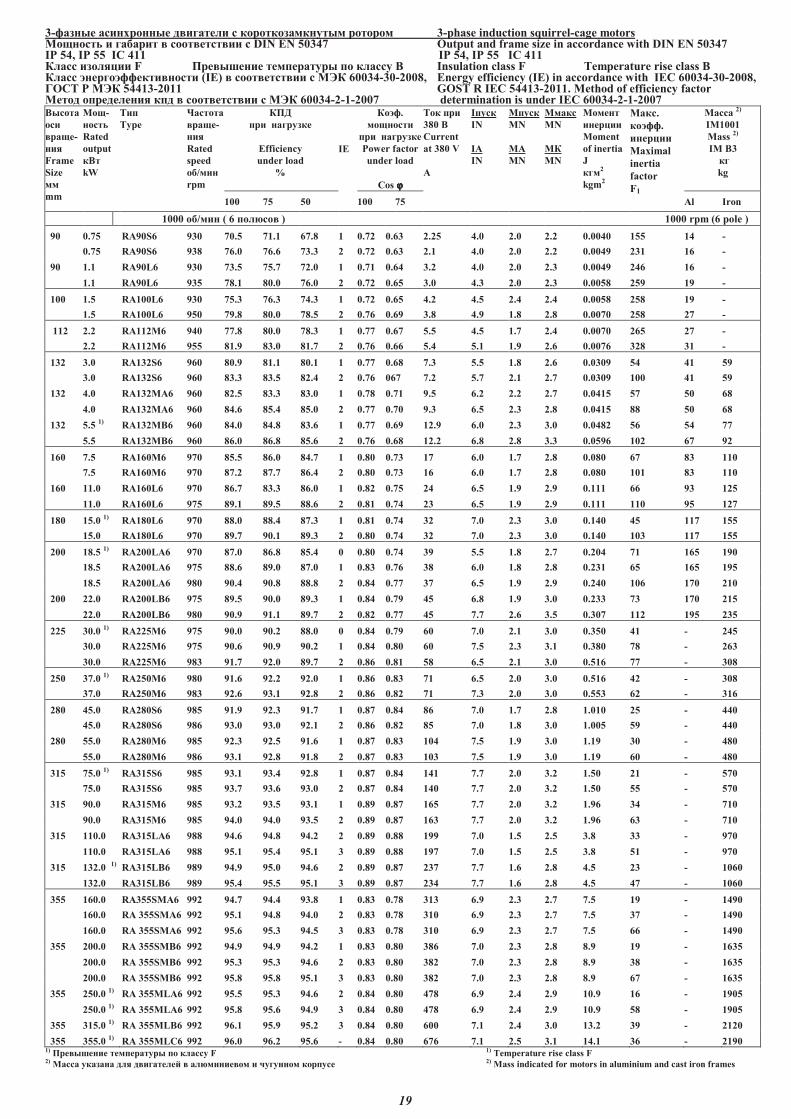
3-������ ��������� � ������� � ��������������� ����� 3-phase induction squirrel-cage motors �������� � ������ ���� ���� �� � DIN EN 50347 Output and frame size in accordance with DIN EN 50347 IP 54, IP 55 IC 411 IP 54, IP 55 IC 411 ����� �������� F �� ������ ��������� �� ������ � Insulation class F Temperature rise class B ����� ������������ ����� (IE) ���� ���� �� � � � 60034-30-2008, Energy efficiency (IE) in accordance with IEC 60034-30-2008, !"#$ % � � 54413-2011 GOS$ R IEC 54413-2011. Method of efficiency factor ����� ���������� ��� ���� ���� �� � � � 60034-2-1-2007 determination is under IEC 60034-2-1-2007 ������
���
���-
���
Frame
Size
��
mm
���-
�����
Rated
output
���
kW
$��
Type
&������
���-
���
Rated
speed
��/���
rpm
��'
�� �������
Efficiency
under load
%
IE
����.
��������
�� �������
Power factor
under load
Cos ϕϕϕϕ
$�� ��
380 �
Current
at 380 V
(
I����
IN
IA
IN
M����
MN
MA
MN
M����
MN
M�
MN
������
������
Moment
of inertia
J
���2
kgm2
����.
�����.
������
Maximal
inertia
factor
F1
�����2)
IM1001
Mass 2)
IM B3
��
kg
100 75 50 100 75 Al Iron
1000 ��/��� ( 6 ���)�� ) 1000 rpm (6 pole )
90 0.75 RA90S6 930 70.5 71.1 67.8 1 0.72 0.63 2.25 4.0 2.0 2.2 0.0040 155 14 -
0.75 RA90S6 938 76.0 76.6 73.3 2 0.72 0.63 2.1 4.0 2.0 2.2 0.0049 231 16 -
90 1.1 RA90L6 930 73.5 75.7 72.0 1 0.71 0.64 3.2 4.0 2.0 2.3 0.0049 246 16 -
1.1 RA90L6 935 78.1 80.0 76.0 2 0.72 0.65 3.0 4.3 2.0 2.3 0.0058 259 19 -
100 1.5 RA100L6 930 75.3 76.3 74.3 1 0.72 0.65 4.2 4.5 2.4 2.4 0.0058 258 19 -
1.5 RA100L6 950 79.8 80.0 78.5 2 0.76 0.69 3.8 4.9 1.8 2.8 0.0070 258 27 -
112 2.2 RA112M6 940 77.8 80.0 78.3 1 0.77 0.67 5.5 4.5 1.7 2.4 0.0070 265 27 -
2.2 RA112M6 955 81.9 83.0 81.7 2 0.76 0.66 5.4 5.1 1.9 2.6 0.0076 328 31 -
132 3.0 RA132S6 960 80.9 81.1 80.1 1 0.77 0.68 7.3 5.5 1.8 2.6 0.0309 54 41 59
3.0 RA132S6 960 83.3 83.5 82.4 2 0.76 067 7.2 5.7 2.1 2.7 0.0309 100 41 59
132 4.0 RA132MA6 960 82.5 83.3 83.0 1 0.78 0.71 9.5 6.2 2.2 2.7 0.0415 57 50 68
4.0 RA132MA6 960 84.6 85.4 85.0 2 0.77 0.70 9.3 6.5 2.3 2.8 0.0415 88 50 68
132 5.5 1)
RA132MB6 960 84.0 84.8 83.6 1 0.77 0.69 12.9 6.0 2.3 3.0 0.0482 56 54 77
5.5 RA132MB6 960 86.0 86.8 85.6 2 0.76 0.68 12.2 6.8 2.8 3.3 0.0596 102 67 92
160 7.5 RA160M6 970 85.5 86.0 84.7 1 0.80 0.73 17 6.0 1.7 2.8 0.080 67 83 110
7.5 RA160M6 970 87.2 87.7 86.4 2 0.80 0.73 16 6.0 1.7 2.8 0.080 101 83 110
160 11.0 RA160L6 970 86.7 83.3 86.0 1 0.82 0.75 24 6.5 1.9 2.9 0.111 66 93 125
11.0 RA160L6 975 89.1 89.5 88.6 2 0.81 0.74 23 6.5 1.9 2.9 0.111 110 95 127
180 15.0 1)
RA180L6 970 88.0 88.4 87.3 1 0.81 0.74 32 7.0 2.3 3.0 0.140 45 117 155
15.0 RA180L6 970 89.7 90.1 89.3 2 0.80 0.74 32 7.0 2.3 3.0 0.140 103 117 155
200 18.5 1)
RA200LA6 970 87.0 86.8 85.4 0 0.80 0.74 39 5.5 1.8 2.7 0.204 71 165 190
18.5 RA200LA6 975 88.6 89.0 87.0 1 0.83 0.76 38 6.0 1.8 2.8 0.231 65 165 195
18.5 RA200LA6 980 90.4 90.8 88.8 2 0.84 0.77 37 6.5 1.9 2.9 0.240 106 170 210
200 22.0 RA200LB6 975 89.5 90.0 89.3 1 0.84 0.79 45 6.8 1.9 3.0 0.233 73 170 215
22.0 RA200LB6 980 90.9 91.1 89.7 2 0.82 0.77 45 7.7 2.6 3.5 0.307 112 195 235
225 30.0 1)
RA225M6 975 90.0 90.2 88.0 0 0.84 0.79 60 7.0 2.1 3.0 0.350 41 - 245
30.0 RA225M6 975 90.6 90.9 90.2 1 0.84 0.80 60 7.5 2.3 3.1 0.380 78 - 263
30.0 RA225M6 983 91.7 92.0 89.7 2 0.86 0.81 58 6.5 2.1 3.0 0.516 77 - 308
250 37.0 1)
RA250M6 980 91.6 92.2 92.0 1 0.86 0.83 71 6.5 2.0 3.0 0.516 42 - 308
37.0 RA250M6 983 92.6 93.1 92.8 2 0.86 0.82 71 7.3 2.0 3.0 0.553 62 - 316
280 45.0 RA280S6 985 91.9 92.3 91.7 1 0.87 0.84 86 7.0 1.7 2.8 1.010 25 - 440
45.0 RA280S6 986 93.0 93.0 92.1 2 0.86 0.82 85 7.0 1.8 3.0 1.005 59 - 440
280 55.0 RA280M6 985 92.3 92.5 91.6 1 0.87 0.83 104 7.5 1.9 3.0 1.19 30 - 480
55.0 RA280M6 986 93.1 92.8 91.8 2 0.87 0.83 103 7.5 1.9 3.0 1.19 60 - 480
315 75.01)
RA315S6 985 93.1 93.4 92.8 1 0.87 0.84 141 7.7 2.0 3.2 1.50 21 - 570
75.0 RA315S6 985 93.7 93.6 93.0 2 0.87 0.84 140 7.7 2.0 3.2 1.50 55 - 570
315 90.0 RA315M6 985 93.2 93.5 93.1 1 0.89 0.87 165 7.7 2.0 3.2 1.96 34 - 710
90.0 RA315M6 985 94.0 94.0 93.5 2 0.89 0.87 163 7.7 2.0 3.2 1.96 63 - 710
315 110.0 RA315LA6 988 94.6 94.8 94.2 2 0.89 0.88 199 7.0 1.5 2.5 3.8 33 - 970
110.0 RA315LA6 988 95.1 95.4 95.1 3 0.89 0.88 197 7.0 1.5 2.5 3.8 51 - 970
315 132.0 1)
RA315LB6 989 94.9 95.0 94.6 2 0.89 0.87 237 7.7 1.6 2.8 4.5 23 - 1060
132.0 RA315LB6 989 95.4 95.5 95.1 3 0.89 0.87 234 7.7 1.6 2.8 4.5 47 - 1060
355 160.0 RA355S�(6 992 94.7 94.4 93.8 1 0.83 0.78 313 6.9 2.3 2.7 7.5 19 - 1490
160.0 RA 355S�(6 992 95.1 94.8 94.0 2 0.83 0.78 310 6.9 2.3 2.7 7.5 37 - 1490
160.0 RA 355S�(6 992 95.6 95.3 94.5 3 0.83 0.78 310 6.9 2.3 2.7 7.5 66 - 1490
355 200.0 RA 355S��6 992 94.9 94.9 94.2 1 0.83 0.80 386 7.0 2.3 2.8 8.9 19 - 1635
200.0 RA 355S��6 992 95.3 95.3 94.6 2 0.83 0.80 382 7.0 2.3 2.8 8.9 38 - 1635
200.0 RA 355S��6 992 95.8 95.8 95.1 3 0.83 0.80 382 7.0 2.3 2.8 8.9 67 - 1635
355 250.0 1)
RA 355MLA6 992 95.5 95.3 94.6 2 0.84 0.80 478 6.9 2.4 2.9 10.9 16 - 1905
250.0 1)
RA 355MLA6 992 95.8 95.6 94.9 3 0.84 0.80 478 6.9 2.4 2.9 10.9 58 - 1905
355 315.0 1)
RA 355MLB6 992 96.1 95.9 95.2 3 0.84 0.80 600 7.1 2.4 3.0 13.2 39 - 2120
355 355.0 1)
RA 355ML#6 992 96.0 96.2 95.6 - 0.84 0.80 676 7.1 2.5 3.1 14.1 36 - 21901) �� ������ ��������� �� ������ F 1) Temperature rise class F 2) ����� ������� ��� � �������* ��)����� �� � +������� ������ 2) Mass indicated for motors in aluminium and cast iron frames
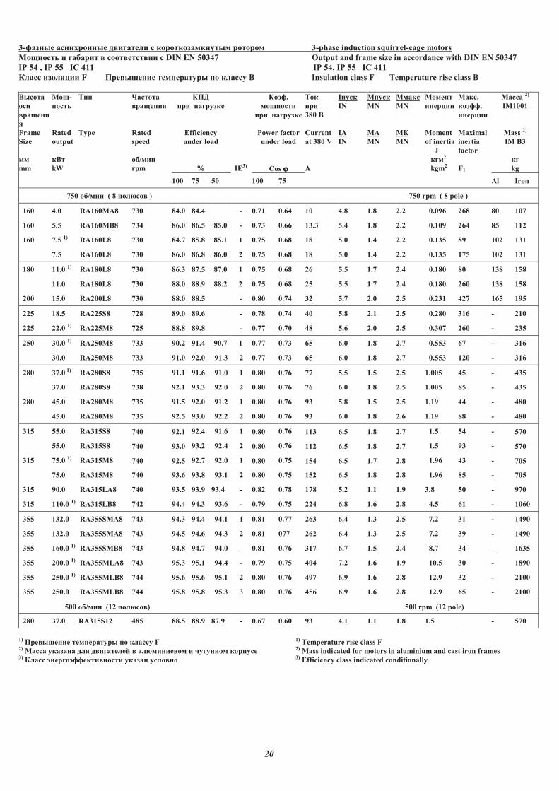
20
3-������ ��������� � ������� � ��������������� ����� 3-phase induction squirrel-cage motors
�������� � ������ ���� ���� �� � DIN EN 50347 Output and frame size in accordance with DIN EN 50347
IP 54 , IP 55 IC 411 IP 54, IP 55 IC 411
����� �������� F �� ������ ��������� �� ������ � Insulation class F Temperature rise class B
������
���
�����
�
Frame
Size
��
mm
���-
�����
Rated
output
���
kW
���
Type
������
������
Rated
speed
��/���
rpm
��!
�� �������
Efficiency
under load
% IE3)
��"�.
��������
�� �������
Power factor
under load
Cos ϕϕϕϕ
���
��
380 �
Current
at 380 V
#
I����
IN
IA
IN
M����
MN
MA
MN
M����
MN
M�
MN
������
������
Moment
of inertia
J
���2
kgm2
����.
��"��.
������
Maximal
inertia
factor
F1
����� 2)
IM1001
Mass 2)
IM B3
��
kg
100 75 50 100 75 Al Iron
750 ��/��� ( 8 ���$�� ) 750 rpm ( 8 pole )
160 4.0 RA160MA8 730 84.0 84.4 - 0.71 0.64 10 4.8 1.8 2.2 0.096 268 80 107
160 5.5 RA160MB8 734 86.0 86.5 85.0 - 0.73 0.66 13.3 5.4 1.8 2.2 0.109 264 85 112
160 7.5 1) RA160L8 730 84.7 85.8 85.1 1 0.75 0.68 18 5.0 1.4 2.2 0.135 89 102 131
7.5 RA160L8 730 86.0 86.8 86.0 2 0.75 0.68 18 5.0 1.4 2.2 0.135 175 102 131
180 11.0 1) RA180L8 730 86.3 87.5 87.0 1 0.75 0.68 26 5.5 1.7 2.4 0.180 80 138 158
11.0 RA180L8 730 88.0 88.9 88.2 2 0.75 0.68 25 5.5 1.7 2.4 0.180 260 138 158
200 15.0 RA200L8 730 88.0 88.5 - 0.80 0.74 32 5.7 2.0 2.5 0.231 427 165 195
225 18.5 RA225S8 728 89.0 89.6 - 0.78 0.74 40 5.8 2.1 2.5 0.280 316 - 210
225 22.0 1) RA225M8 725 88.8 89.8 - 0.77 0.70 48 5.6 2.0 2.5 0.307 260 - 235
250 30.0 1) RA250M8 733 90.2 91.4 90.7 1 0.77 0.73 65 6.0 1.8 2.7 0.553 67 - 316
30.0 RA250M8 733 91.0 92.0 91.3 2 0.77 0.73 65 6.0 1.8 2.7 0.553 120 - 316
280 37.0 1) RA280S8 735 91.1 91.6 91.0 1 0.80 0.76 77 5.5 1.5 2.5 1.005 45 - 435
37.0 RA280S8 738 92.1 93.3 92.0 2 0.80 0.76 76 6.0 1.8 2.5 1.005 85 - 435
280 45.0 RA280M8 735 91.5 92.0 91.2 1 0.80 0.76 93 5.8 1.5 2.5 1.19 44 - 480
45.0 RA280M8 735 92.5 93.0 92.2 2 0.80 0.76 93 6.0 1.8 2.6 1.19 88 - 480
315 55.0 RA315S8 740 92.1 92.4 91.6 1 0.80 0.76 113 6.5 1.8 2.7 1.5 54 - 570
55.0 RA315S8 740 93.0 93.2 92.4 2 0.80 0.76 112 6.5 1.8 2.7 1.5 93 - 570
315 75.0 1) RA315M8 740 92.5 92.7 92.0 1 0.80 0.75 154 6.5 1.7 2.8 1.96 43 - 705
75.0 RA315M8 740 93.6 93.8 93.1 2 0.80 0.75 152 6.5 1.8 2.8 1.96 85 - 705
315 90.0 RA315LA8 740 93.5 93.9 93.4 - 0.82 0.78 178 5.2 1.1 1.9 3.8 50 - 970
315 110.0 1) RA315LB8 742 94.4 94.3 93.6 - 0.79 0.75 224 6.8 1.6 2.8 4.5 61 - 1060
355 132.0 RA355S�#8 743 94.3 94.4 94.1 1 0.81 0.77 263 6.4 1.3 2.5 7.2 31 - 1490
355 132.0 RA355S�#8 743 94.5 94.6 94.3 2 0.81 077 262 6.4 1.3 2.5 7.2 39 - 1490
355 160.0 1) RA355S��8 743 94.8 94.7 94.0 - 0.81 0.76 317 6.7 1.5 2.4 8.7 34 - 1635
355 200.0 1) RA355MLA8 743 95.3 95.1 94.4 - 0.79 0.75 404 7.2 1.6 1.9 10.5 30 - 1890
355 250.0 1) RA355MLB8 744 95.6 95.6 95.1 2 0.80 0.76 497 6.9 1.6 2.8 12.9 32 - 2100
355 250.0 RA355MLB8 744 95.8 95.8 95.3 3 0.80 0.76 456 6.9 1.6 2.8 12.9 65 - 2100
500 ��/��� (12 ���$�� ) 500 rpm (12 pole)
280 37.0 R#315S12 485 88.5 88.9 87.9 - 0.67 0.60 93 4.1 1.1 1.8 1.5 - 570
1) �� ������ ��������� �� ������ F 1) Temperature rise class F 2) ����� ������� ��� � �������% ��$����� �� � &������� ������ 2) Mass indicated for motors in aluminium and cast iron frames 3) ����� "����"������ ����� ������ ���� �� 3) Efficiency class indicated conditionally
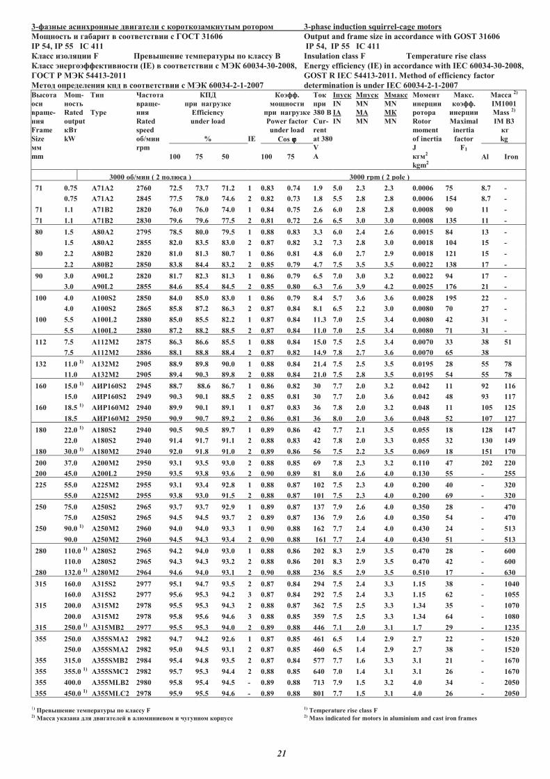
21
3-������ ��������� � ������� � ��������������� ����� 3-phase induction squirrel-cage motors
�������� � ������ ���� ���� �� � ���� 31606 Output and frame size in accordance with GOST 31606
IP 54, IP 55 IC 411 IP 54, IP 55 IC 411
����� �������� F �� � ���� ���!����� !� ������ " Insulation class F Temperature rise class
����� #����#������ ����� (IE) ���� ���� �� � �$� 60034-30-2008, Energy efficiency (IE) in accordance with IEC 60034-30-2008,
���� % �$� 54413-2011 GOS� R IEC 54413-2011. Method of efficiency factor
����� �!�������� �!� ���� ���� �� � �$� 60034-2-1-2007 determination is under IEC 60034-2-1-2007
"�����
���
���-
���
Frame
Size
��
mm
���-
�����
Rated
output
�"�
kW
��!
Type
&������
���-
���
Rated
speed
��/���
rpm
��'
!� �������
Efficiency
under load
% IE
��#��.
��������
!� �������
Power factor
under load
Cos ϕϕϕϕ
���
!�
380 "
Cur-
rent
at 380
V
(
I!���
IN
IA
IN
M!���
MN
MA
MN
M����
MN
M�
MN
������
������
����
Rotor
moment
of inertia
J
���2
kgm2
����.
��#��.
������
Maximal
inertia
factor
F1
����� 2)
IM1001
Mass 2)
IM B3
��
kg
100 75 50 100 75 Al Iron
3000 ��/��� ( 2 !��)�� ) 3000 rpm ( 2 pole )
71 0.75 A71A2 2760 72.5 73.7 71.2 1 0.83 0.74 1.9 5.0 2.3 2.3 0.0006 75 8.7 -
0.75 A71A2 2845 77.5 78.0 74.6 2 0.82 0.73 1.8 5.5 2.8 2.8 0.0006 154 8.7 -
71 1.1 A71B2 2820 76.0 76.0 74.0 1 0.84 0.75 2.6 6.0 2.8 2.8 0.0008 90 11 -
71 1.1 A71B2 2830 79.6 79.6 77.5 2 0.81 0.72 2.6 6.5 3.0 3.0 0.0008 135 11 -
80 1.5 A80A2 2795 78.5 80.0 79.5 1 0.88 0.83 3.3 6.0 2.4 2.6 0.0015 84 13 -
1.5 A80A2 2855 82.0 83.5 83.0 2 0.87 0.82 3.2 7.3 2.8 3.0 0.0018 104 15 -
80 2.2 A80B2 2820 81.0 81.3 80.7 1 0.86 0.81 4.8 6.0 2.7 2.9 0.0018 121 15 -
2.2 A80B2 2850 83.8 84.4 83.2 2 0.85 0.79 4.7 7.5 3.5 3.5 0.0022 138 17 -
90 3.0 A90L2 2820 81.7 82.3 81.3 1 0.86 0.79 6.5 7.0 3.0 3.2 0.0022 94 17 -
3.0 A90L2 2855 84.6 85.4 84.5 2 0.85 0.80 6.3 7.6 3.9 4.2 0.0025 176 21 -
100 4.0 A100S2 2850 84.0 85.0 83.0 1 0.86 0.79 8.4 5.7 3.6 3.6 0.0028 195 22 -
4.0 A100S2 2865 85.8 87.2 86.3 2 0.87 0.84 8.1 6.5 2.2 3.0 0.0080 70 27 -
100 5.5 A100L2 2880 85.0 85.5 82.2 1 0.87 0.84 11.3 7.0 2.5 3.4 0.0080 42 31 -
5.5 A100L2 2880 87.2 88.2 88.5 2 0.87 0.84 11.0 7.0 2.5 3.4 0.0080 71 31 -
112 7.5 A112M2 2875 86.3 86.6 85.5 1 0.88 0.84 15.0 7.5 2.5 3.4 0.0070 33 38 51
7.5 A112M2 2886 88.1 88.8 88.4 2 0.87 0.82 14.9 7.8 2.7 3.6 0.0070 65 38
132 11.0 1) (132�2 2905 88.9 89.8 90.0 1 0.88 0.84 21.4 7.5 2.5 3.5 0.0195 28 55 78
11.0 A132M2 2905 89.4 90.3 89.8 2 0.88 0.84 21.0 7.5 2.8 3.5 0.0195 54 55 78
160 15.0 1) (*%160S2 2945 88.7 88.6 86.7 1 0.86 0.82 30 7.7 2.0 3.2 0.042 11 92 116
15.0 (*%160S2 2949 90.3 90.1 88.5 2 0.85 0.81 30 7.7 2.0 3.6 0.042 48 93 117
160 18.5 1) (*%160�2 2940 89.9 90.1 89.1 1 0.87 0.83 36 7.8 2.0 3.2 0.048 11 105 125
18.5 (*%160�2 2950 90.9 90.7 89.2 2 0.86 0.81 36 8.0 2.0 3.6 0.048 52 107 127
180 22.0 1) A180S2 2940 90.5 90.5 89.7 1 0.89 0.86 42 7.7 2.1 3.5 0.055 18 128 147
22.0 A180S2 2940 91.4 91.7 91.1 2 0.88 0.83 42 7.8 2.0 3.3 0.055 32 130 149
180 30.0 1) A180M2 2940 92.0 91.8 91.0 2 0.89 0.86 56 7.5 2.2 3.5 0.069 18 151 170
200 37.0 A200M2 2950 93.1 93.5 93.0 2 0.88 0.85 69 7.8 2.3 3.2 0.110 47 202 220
200 45.0 A200L2 2950 93.5 93.8 93.6 2 0.90 0.89 81 8.0 2.6 4.0 0.130 55 - 255
225 55.0 A225M2 2955 93.1 93.4 92.8 1 0.88 0.87 102 7.5 2.3 4.0 0.200 40 - 320
55.0 A225M2 2955 93.8 93.0 91.5 2 0.88 0.87 101 7.5 2.3 4.0 0.200 69 - 320
250 75.0 A250S2 2965 93.7 93.7 92.9 1 0.89 0.87 137 7.9 2.6 4.0 0.350 28 - 470
75.0 A250S2 2965 94.5 94.5 93.7 2 0.89 0.87 136 7.9 2.6 4.0 0.350 54 - 470
250 90.0 1) A250M2 2960 94.0 94.0 93.3 1 0.90 0.88 162 7.7 2.4 4.0 0.430 24 - 513
90.0 A250M2 2960 94.5 94.3 93.4 2 0.90 0.88 161 7.7 2.4 4.0 0.430 51 - 513
280 110.0 1) A280S2 2965 94.2 94.0 93.0 1 0.88 0.86 202 8.3 2.9 3.5 0.470 28 - 600
110.0 A280S2 2965 94.3 94.3 93.2 2 0.88 0.86 201 8.3 2.9 3.5 0.470 42 - 600
280 132.0 1) A280M2 2964 94.6 94.0 93.1 2 0.90 0.88 236 8.5 2.9 3.5 0.510 17 - 630
315 160.0 A315S2 2977 95.1 94.7 93.5 2 0.87 0.84 294 7.5 2.4 3.3 1.15 38 - 1040
160.0 A315S2 2977 95.6 95.3 94.2 3 0.87 0.84 292 7.5 2.4 3.3 1.15 62 - 1055
315 200.0 (315�2 2978 95.5 95.3 94.3 2 0.88 0.87 362 7.5 2.5 3.3 1.34 35 - 1070
200.0 (315�2 2978 95.8 95.6 94.6 3 0.88 0.85 359 7.5 2.5 3.3 1.34 64 - 1080
315 250.0 1) (315�"2 2977 95.5 95.3 94.0 2 0.89 0.88 446 7.1 2.0 3.1 1.7 29 - 1235
355 250.0 A355S�(2 2982 94.7 94.2 92.6 1 0.87 0.85 461 6.5 1.4 2.9 2.7 22 - 1520
250.0 A355S�(2 2982 95.0 94.5 93.1 2 0.87 0.85 460 6.5 1.4 2.9 2.7 38 - 1520
355 315.0 A355S�B2 2984 95.4 94.8 93.5 2 0.87 0.84 577 7.7 1.6 3.3 3.1 21 - 1670
355 355.0 1) A355S�C2 2982 95.7 95.3 94.4 2 0.88 0.85 640 7.0 1.4 3.1 3.1 26 - 1670
355 400.0 A355�LB2 2980 95.8 95.4 94.5 - 0.89 0.88 713 7.9 1.5 3.2 4.0 34 - 2050
355 450.0 1) A355�LC2 2978 95.9 95.5 94.6 - 0.89 0.88 801 7.7 1.5 3.1 4.0 26 - 2050
1) �� � ���� ���!����� !� ������ F 1) Temperature rise class F 2) ����� ������� ��� � �������+ ��)����� �� � ,������� ��!��� 2) Mass indicated for motors in aluminium and cast iron frames
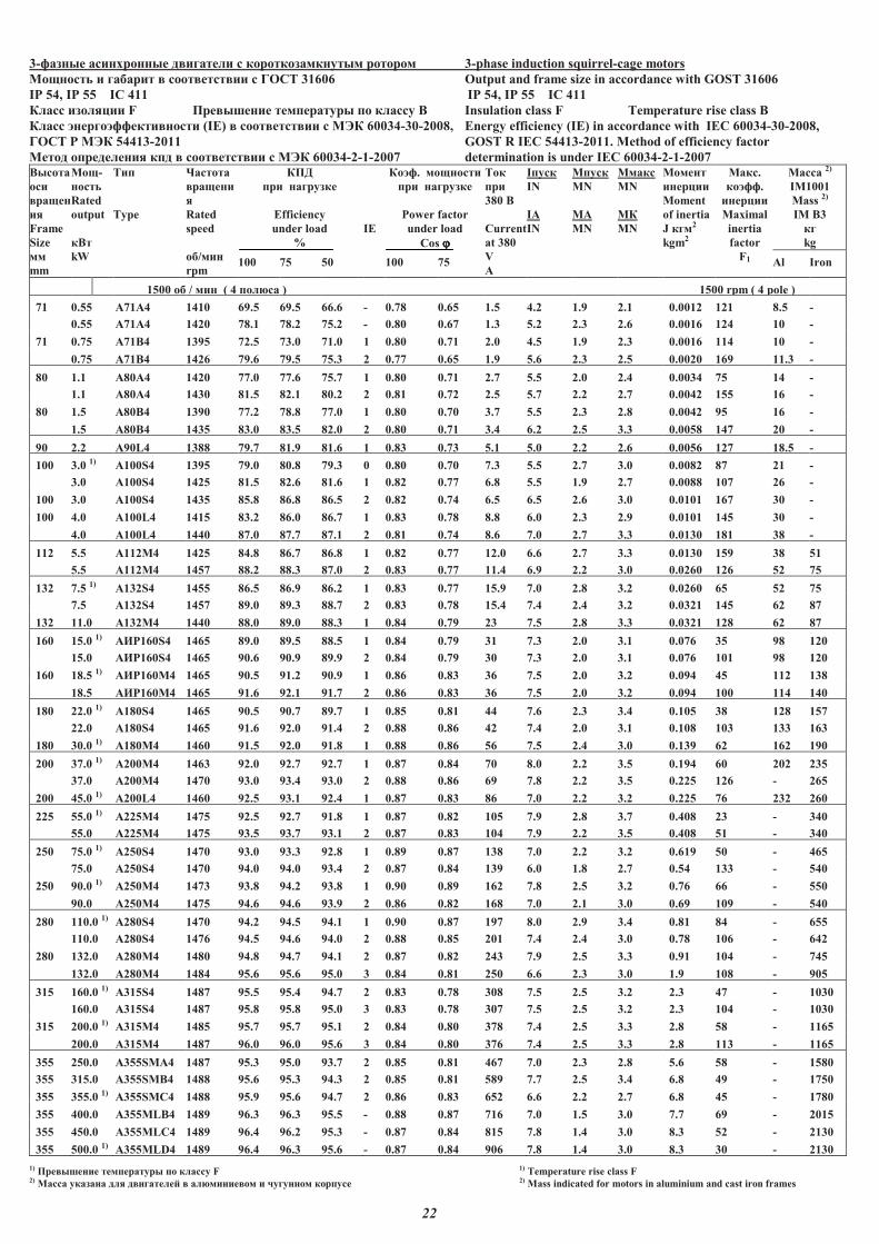
10
22
3-������ ��������� � ������� � ��������������� ����� 3-phase induction squirrel-cage motors
�������� � ������ ���� ���� �� � ���� 31606 Output and frame size in accordance with GOST 31606
IP 54, IP 55 IC 411 IP 54, IP 55 IC 411
����� �������� F �� � ���� ���!����� !� ������ " Insulation class F Temperature rise class B
����� #����#������ ����� (IE) ���� ���� �� � �$� 60034-30-2008, Energy efficiency (IE) in accordance with IEC 60034-30-2008,
���� % �$� 54413-2011 GOS� R IEC 54413-2011. Method of efficiency factor
����� �!�������� �!� ���� ���� �� � �$� 60034-2-1-2007 determination is under IEC 60034-2-1-2007
"�����
���
����
��
Frame
Size
��
mm
���-
�����
Rated
output
�"�
kW
��!
Type
&������
�����
�
Rated
speed
��/���
rpm
��'
!� �������
Efficiency
under load
%
IE
��#�. ��������
!� �������
Power factor
under load
Cos ϕϕϕϕ
���
!�
380 "
Current
at 380
V
(
I!���
IN
IA
IN
M!���
MN
MA
MN
M����
MN
M�
MN
������
������
Moment
of inertia
J ���2
kgm2
����.
��#��.
������
Maximal
inertia
factor
F1
����� 2)
IM1001
Mass 2)
IM B3
��
kg
100 75 50 100 75 Al Iron
1500 �� / ��� ( 4 !��)�� ) 1500 rpm ( 4 pole )
71 0.55 A71A4 14 69.5 69.5 66.6 - 0.78 0.65 1.5 4.2 1.9 2.1 0.0012 121 8.5 -
0.55 A71A4 1420 78.1 78.2 75.2 - 0.80 0.67 1.3 5.2 2.3 2.6 0.0016 124 10 -
71 0.75 A71B4 1395 72.5 73.0 71.0 1 0.80 0.71 2.0 4.5 1.9 2.3 0.0016 114 10 -
0.75 A71B4 1426 79.6 79.5 75.3 2 0.77 0.65 1.9 5.6 2.3 2.5 0.0020 169 11.3 -
80 1.1 A80A4 1420 77.0 77.6 75.7 1 0.80 0.71 2.7 5.5 2.0 2.4 0.0034 75 14 -
1.1 A80A4 1430 81.5 82.1 80.2 2 0.81 0.72 2.5 5.7 2.2 2.7 0.0042 155 16 -
80 1.5 A80B4 1390 77.2 78.8 77.0 1 0.80 0.70 3.7 5.5 2.3 2.8 0.0042 95 16 -
1.5 A80B4 1435 83.0 83.5 82.0 2 0.80 0.71 3.4 6.2 2.5 3.3 0.0058 147 20 -
90 2.2 A90L4 1388 79.7 81.9 81.6 1 0.83 0.73 5.1 5.0 2.2 2.6 0.0056 127 18.5 -
100 3.0 1) A100S4 1395 79.0 80.8 79.3 0 0.80 0.70 7.3 5.5 2.7 3.0 0.0082 87 21 -
3.0 A100S4 1425 81.5 82.6 81.6 1 0.82 0.77 6.8 5.5 1.9 2.7 0.0088 107 26 -
100 3.0 A100S4 1435 85.8 86.8 86.5 2 0.82 0.74 6.5 6.5 2.6 3.0 0.0101 167 30 -
100 4.0 A100L4 1415 83.2 86.0 86.7 1 0.83 0.78 8.8 6.0 2.3 2.9 0.0101 145 30 -
4.0 A100L4 1440 87.0 87.7 87.1 2 0.81 0.74 8.6 7.0 2.7 3.3 0.0130 181 38 -
112 5.5 A112M4 1425 84.8 86.7 86.8 1 0.82 0.77 12.0 6.6 2.7 3.3 0.0130 159 38 51
5.5 A112M4 1457 88.2 88.3 87.0 2 0.83 0.77 11.4 6.9 2.2 3.0 0.0260 126 52 75
132 7.5 1) A132S4 1455 86.5 86.9 86.2 1 0.83 0.77 15.9 7.0 2.8 3.2 0.0260 65 52 75
7.5 A132S4 1457 89.0 89.3 88.7 2 0.83 0.78 15.4 7.4 2.4 3.2 0.0321 145 62 87
132 11.0 A132M4 1440 88.0 89.0 88.3 1 0.84 0.79 23 7.5 2.8 3.3 0.0321 128 62 87
160 15.0 1) (*%160S4 1465 89.0 89.5 88.5 1 0.84 0.79 31 7.3 2.0 3.1 0.076 35 98 120
15.0 (*%160S4 1465 90.6 90.9 89.9 2 0.84 0.79 30 7.3 2.0 3.1 0.076 101 98 120
160 18.5 1) (*%160M4 1465 90.5 91.2 90.9 1 0.86 0.83 36 7.5 2.0 3.2 0.094 45 112 138
18.5 (*%160M4 1465 91.6 92.1 91.7 2 0.86 0.83 36 7.5 2.0 3.2 0.094 100 114 140
180 22.0 1) (180S4 1465 90.5 90.7 89.7 1 0.85 0.81 44 7.6 2.3 3.4 0.105 38 128 157
22.0 (180S4 1465 91.6 92.0 91.4 2 0.88 0.86 42 7.4 2.0 3.1 0.108 103 133 163
180 30.0 1) (180M4 1460 91.5 92.0 91.8 1 0.88 0.86 56 7.5 2.4 3.0 0.139 62 162 190
200 37.0 1) A200M4 1463 92.0 92.7 92.7 1 0.87 0.84 70 8.0 2.2 3.5 0.194 60 202 235
37.0 A200M4 1470 93.0 93.4 93.0 2 0.88 0.86 69 7.8 2.2 3.5 0.225 126 - 265
200 45.0 1) A200L4 1460 92.5 93.1 92.4 1 0.87 0.83 86 7.0 2.2 3.2 0.225 76 232 260
225 55.0 1) A225M4 1475 92.5 92.7 91.8 1 0.87 0.82 105 7.9 2.8 3.7 0.408 23 - 340
55.0 A225M4 1475 93.5 93.7 93.1 2 0.87 0.83 104 7.9 2.2 3.5 0.408 51 - 340
250 75.0 1) A250S4 1470 93.0 93.3 92.8 1 0.89 0.87 138 7.0 2.2 3.2 0.619 50 - 465
75.0 A250S4 1470 94.0 94.0 93.4 2 0.87 0.84 139 6.0 1.8 2.7 0.54 133 - 540
250 90.0 1) A250M4 1473 93.8 94.2 93.8 1 0.90 0.89 162 7.8 2.5 3.2 0.76 66 - 550
90.0 A250M4 1475 94.6 94.6 93.9 2 0.86 0.82 168 7.0 2.1 3.0 0.69 109 - 540
280 110.0 1) A280S4 1470 94.2 94.5 94.1 1 0.90 0.87 197 8.0 2.9 3.4 0.81 84 - 655
110.0 A280S4 1476 94.5 94.6 94.0 2 0.88 0.85 201 7.4 2.4 3.0 0.78 106 - 642
280 132.0 A280M4 1480 94.8 94.7 94.1 2 0.87 0.82 243 7.9 2.5 3.3 0.91 104 - 745
132.0 A280M4 1484 95.6 95.6 95.0 3 0.84 0.81 250 6.6 2.3 3.0 1.9 108 - 905
315 160.0 1) (315S4 1487 95.5 95.4 94.7 2 0.83 0.78 308 7.5 2.5 3.2 2.3 47 - 1030
160.0 (315S4 1487 95.8 95.8 95.0 3 0.83 0.78 307 7.5 2.5 3.2 2.3 104 - 1030
315 200.0 1) (315�4 1485 95.7 95.7 95.1 2 0.84 0.80 378 7.4 2.5 3.3 2.8 58 - 1165
200.0 (315�4 1487 96.0 96.0 95.6 3 0.84 0.80 376 7.4 2.5 3.3 2.8 113 - 1165
355 250.0 A355S�(4 1487 95.3 95.0 93.7 2 0.85 0.81 467 7.0 2.3 2.8 5.6 58 - 1580
355 315.0 A355S�"4 1488 95.6 95.3 94.3 2 0.85 0.81 589 7.7 2.5 3.4 6.8 49 - 1750
355 355.0 1) (355SMC4 1488 95.9 95.6 94.7 2 0.86 0.83 652 6.6 2.2 2.7 6.8 45 - 1780
355 400.0 (355MLB4 1489 96.3 96.3 95.5 - 0.88 0.87 716 7.0 1.5 3.0 7.7 69 - 2015
355 450.0 A355MLC4 1489 96.4 96.2 95.3 - 0.87 0.84 815 7.8 1.4 3.0 8.3 52 - 2130
355 500.0 1) A355MLD4 1489 96.4 96.3 95.6 - 0.87 0.84 906 7.8 1.4 3.0 8.3 30 - 2130
1) �� � ���� ���!����� !� ������ F 1) Temperature rise class F 2) ����� ������� ��� � �������+ ��)����� �� � ,������� ��!��� 2) Mass indicated for motors in aluminium and cast iron frames

23
3-������ ��������� � ������� � ��������������� ����� 3-phase induction squirrel-cage motors�������� � ������� ���� ���� �� � ���� 31606 Output and frame size in accordance with GOS� 31606 IP 54 IP 55 IC 411 IP 54 IP 55 IC 411 ����� �������� F �� � ���� ���!����� !� ������ " Insulation class F Temperature rise class B ����� #����#������ ����� (IE) ���� ���� �� � �$� 60034-30-2008, Energy efficiency (IE) in accordance with IEC 60034-30-2008, ���� % �$� 54413-2011 GOS� R IEC 54413-2011. Method of efficiency factor ����� �!�������� �!� ���� ���� �� � �$� 60034-2-1-2007 determination is under IEC 60034-2-1-2007 "�����
���
����
���
Frame
Size
��
mm
���-
�����
Rated
output
�"�
kW
��!
Type
&������
"���-
���
Rated
speed
��/���
rpm
��'
!� �������
Efficiency
under load
%
IE
��#�.
��������
!� �������
Power factor
under load
Cos ϕϕϕϕ
��� !�
380 "
Current
at 380 V
(
I!���
IN
IA
IN
M!���
MN
MA
MN
M����
MN
M�
MN
������
������
Moment
of inertia
J
���2
kgm2
����.
��#��.
������
Maximal
inertia
factor
F1
�����2)
IM1001
Mass 2)
IM B3
��
kg
100 75 50 100 75 Al Iron
1000 ��/��� ( 6 !��)�� ) 1000 rpm (6 pole )
80 0.75 A80A6 930 70.5 71.1 67.8 1 0.72 0.63 2.25 4.0 2.0 2.2 0.0040 155 14 -
80 0.75 A80A6 938 76.0 76.6 73.3 2 0.72 0.63 2.1 4.0 2.0 2.2 0.0049 231 16 -
80 1.1 A80B6 930 73.5 75.7 72.0 1 0.71 0.64 3.2 4.0 2.0 2.3 0.0049 246 16 -
80 1.1 A80B6 935 78.1 80.0 76.0 2 0.72 0.65 3.0 4.3 2.0 2.3 0.0058 259 19 -
90 1.5 A90L6 930 75.3 76.3 74.3 1 0.72 0.65 4.2 4.5 2.4 2.4 0.0058 258 19 -
100 2.2 A100L6 940 77.8 80.0 78.3 1 0.77 0.67 5.5 4.5 1.7 2.4 0.0070 265 27 -
100 2.2 A100L6 955 81.9 83.0 81.7 2 0.76 0.66 5.4 5.1 1.9 2.6 0.0076 328 31 -
112 3.0 A112MA6 945 81.0 82.0 80.4 1 0.75 0.66 7.5 5.4 2.1 2.9 0.0076 341 31 -
112 3.0 A112MA6 955 83.3 83.5 82.5 2 0.74 0.66 7.4 6.0 2.6 3.3 0.0116 363 42 -
112 4.0 A112MB6 940 81.5 82.5 82.2 1 0.76 0.71 9.8 5.7 2.2 2.8 0.0116 278 42 -
132 5.5 1)
A132S6 960 84.0 84.8 83.6 1 0.77 0.69 12.9 6.0 2.3 3.0 0.0482 56 54 77
5.5 A132S6 960 86.0 86.8 85.6 2 0.76 0.68 12.7 6.8 2.8 3.3 0.0596 102 67 92
132 7.5 A132M6 960 85.0 85.4 84.0 1 0.77 0.69 17.5 6.5 2.8 3.1 0.0596 91 67 92
160 11.0 (*%160S6 970 86.7 83.3 86.0 1 0.82 0.75 24 6.5 1.9 2.9 0.111 66 93 125
11.0 (*%160S6 975 89.1 89.5 88.6 2 0.81 0.74 23.1 6.5 1.9 2.9 0.111 110 95 127
160 15.0 1)
(*%160�6 970 88.0 88.4 87.3 1 0.81 0.74 32 7.0 2.3 3.0 0.140 45 125 145
15.0 (*%160�6 970 89.7 90.1 89.3 2 0.80 0.74 32 7.0 2.3 3.0 0.140 103 117 145
180 18.5 1)
(180M6 970 89.0 90.0 89.5 1 0.85 0.81 37 6.0 2.2 3.0 0.161 56 132 180
200 22.0 A200M6 975 89.5 90.0 89.3 1 0.84 0.79 45 6.8 1.9 3.0 0.233 73 170 215
22.0 A200M6 980 90.9 91.1 89.7 2 0.82 0.77 45 7.7 2.6 3.5 0.307 112 195 235
200 30.0 1)
A200L6 975 90.0 90.2 88.0 0 0.84 0.79 60 7.0 2.1 3.0 0.350 41 205 245
30.0 A200L6 975 90.6 90.9 90.2 1 0.84 0.80 60 7.5 2.3 3.1 0.380 78 - 263
225 37.0 1)
A225M6 980 91.6 92.2 92.0 1 0.86 0.83 71 6.5 2.0 3.0 0.516 42 - 308
37.0 A225M6 983 92.6 93.1 92.8 2 0.86 0.82 71 7.3 2.0 3.0 0.553 62 - 316
250 45.0 A250S6 985 91.9 92.3 91.7 1 0.87 0.84 86 7.0 1.7 2.8 1.01 25 - 440
45.0 A250S6 986 93.0 93.0 92.1 2 0.86 0.83 85 7.5 1.8 3.0 1.01 59 - 440
250 55.0 A250M6 985 92.3 92.5 91.6 1 0.87 0.83 104 7.5 1.9 3.0 1.19 30 - 480
55.0 A250M6 986 93.1 92.8 91.8 2 0.87 0.83 103 7.5 1.9 3.0 1.19 60 - 480
280 75.0 1)
A280S6 985 93.1 93.4 92.8 1 0.87 0.84 141 7.7 2.0 3.2 1.5 21 - 570
75.0 A280S6 985 93.7 93.6 93.0 2 0.87 0.84 140 7.7 2.0 3.2 1.5 55 - 570
280 90.0 A280M6 985 93.2 93.5 93.1 1 0.89 0.87 165 7.7 2.0 3.2 1.96 34 - 710
90.0 A280M6 985 94.0 94.0 93.5 2 0.89 0.87 163 7.7 2.0 3.2 1.96 63 - 710
315 110.0 A315S6 988 94.6 94.8 94.2 2 0.89 0.88 199 7.0 1.5 2.5 3.8 33 - 970
110.0 A315S6 988 95.1 95.4 95.1 3 0.89 0.88 197 7.0 1.5 2.5 3.8 51 - 970
315 132.0 1)
A315M6 989 94.9 95.0 94.6 2 0.89 0.87 237 7.7 1.6 2.8 4.5 23 1060
132.0 A315M6 989 95.4 95.4 95.1 3 0.89 0.87 234 7.7 1.6 2.8 4.5 47 - 1060
355 160.0 A355S�(6 992 94.7 94.4 93.8 1 0.83 0.78 313 6.9 2.3 2.7 7.5 19 - 1490
160.0 A355S�(6 992 95.1 94.8 94.0 2 0.83 0.78 310 6.9 2.3 2.7 7.5 37 - 1490
160.0 A355S�(6 992 95.6 95.3 94.5 3 0.83 0.78 310 6.9 2.3 2.7 7.5 66 - 1490
355 200.0 A355S�"6 992 94.9 94.9 94.2 1 0.83 0.80 386 7.0 2.3 2.8 8.9 19 - 1635
200.0 A355S�"6 992 95.3 95.3 94.6 2 0.83 0.80 382 7.0 2.3 2.8 8.9 38 - 1635
200.0 A355S�"6 992 95.8 95.8 95.1 3 0.83 0.80 382 7.0 2.3 2.8 8.9 67 - 1635
355 250.0 1)
A355MLA6 992 95.5 95.3 94.6 2 0.84 0.80 478 6.9 2.4 2.9 10.9 16 - 1905
250.0 1)
A355MLA6 992 95.8 95.6 94.9 3 0.84 0.80 478 6.9 2.4 2.9 10.9 58 - 1905
355 315.0 1)
A355MLB6 992 96.1 95.9 95.2 3 0.84 0.80 600 7.1 2.4 3.0 13.2 39 - 2120
355 355.0 1)
A355ML�6 992 96.0 96.2 95.6 - 0.84 0.80 676 7.1 2.5 3.1 14.1 36 - 2190
1) �� � ���� ���!����� !� ������ F 1) Temperature rise class F 2) ����� ������� ��� � �������+ ��)����� �� � ,������� ��!��� 2) Mass indicated for motors in aluminium and cast
iron frames
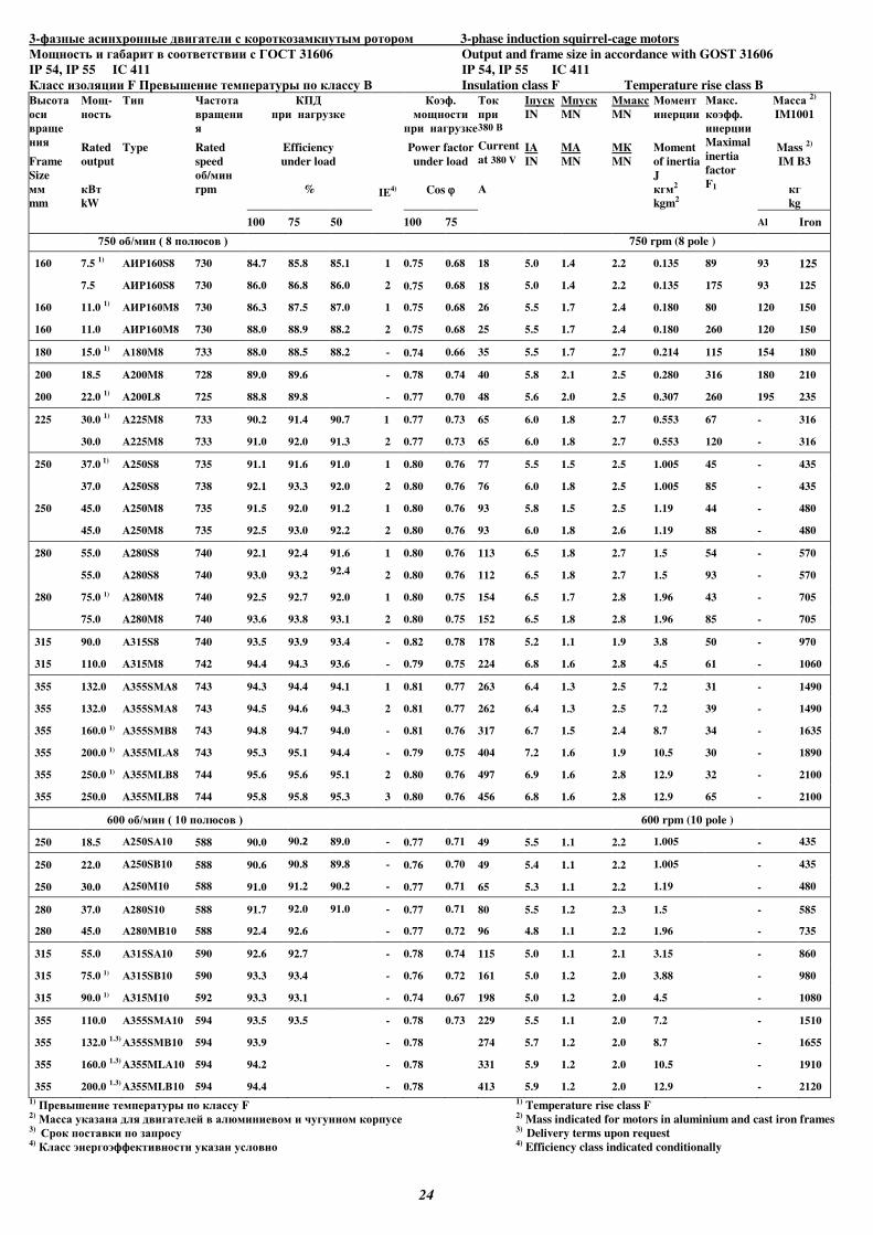
24
3- 3-phase induction squirrel-cage motors
М 31606 Output and frame size in accordance with GOST 31606
IP 54, IP 55 IC 411 IP 54, IP 55 IC 411
К F Insulation class F Temperature rise class B
Frame
Size
mm
М -
Rated
output
kW
Type
Ч
Rated
speed
/
rpm
К
Efficiency
under load
%
IE4)
К .
Power factor
under load
Cos
380
Current
at 380 V
А
I
IN
IA
IN
M
MN
MA
MN
M
MN
MК
MN
М
Moment
of inertia
J 2
kgm2
М .
.
Maximal
inertia
factor
F1
М 2)
IM1001
Mass 2)
IM B3
kg
100 75 50 100 75 Al Iron
750 / ( 8 ) 750 rpm (8 pole )
160 7.5 1)
АИ 160S8 730 84.7 85.8 85.1 1 0.75 0.68 18 5.0 1.4 2.2 0.135 89 93 125
7.5 АИ 160S8 730 86.0 86.8 86.0 2 0.75 0.68 18 5.0 1.4 2.2 0.135 175 93 125
160 11.0 1)
АИ 160M8 730 86.3 87.5 87.0 1 0.75 0.68 26 5.5 1.7 2.4 0.180 80 120 150
160 11.0 АИ 160M8 730 88.0 88.9 88.2 2 0.75 0.68 25 5.5 1.7 2.4 0.180 260 120 150
180 15.0 1) А180M8 733 88.0 88.5 88.2 - 0.74 0.66 35 5.5 1.7 2.7 0.214 115 154 180
200 18.5 A200M8 728 89.0 89.6 - 0.78 0.74 40 5.8 2.1 2.5 0.280 316 180 210
200 22.0 1)
A200L8 725 88.8 89.8 - 0.77 0.70 48 5.6 2.0 2.5 0.307 260 195 235
225 30.0 1)
A225M8 733 90.2 91.4 90.7 1 0.77 0.73 65 6.0 1.8 2.7 0.553 67 - 316
30.0
A225M8 733 91.0 92.0 91.3 2 0.77 0.73 65 6.0 1.8 2.7 0.553 120 - 316
250 37.0 1)
A250S8 735 91.1 91.6 91.0 1 0.80 0.76 77 5.5 1.5 2.5 1.005 45 - 435
37.0
A250S8 738 92.1 93.3 92.0 2 0.80 0.76 76 6.0 1.8 2.5 1.005 85 - 435
250 45.0
A250M8 735 91.5 92.0 91.2 1 0.80 0.76 93 5.8 1.5 2.5 1.19 44 - 480
45.0
A250M8 735 92.5 93.0 92.2 2 0.80 0.76 93 6.0 1.8 2.6 1.19 88 - 480
280 55.0 A280S8 740 92.1 92.4 91.6 1 0.80 0.76 113 6.5 1.8 2.7 1.5 54 - 570
55.0 A280S8 740 93.0 93.2 92.4 2 0.80 0.76 112 6.5 1.8 2.7 1.5 93 - 570
280 75.0 1) A280M8 740 92.5 92.7 92.0 1 0.80 0.75 154 6.5 1.7 2.8 1.96 43 - 705
75.0 A280M8 740 93.6 93.8 93.1 2 0.80 0.75 152 6.5 1.8 2.8 1.96 85 - 705
315 90.0 А315S8 740 93.5 93.9 93.4 - 0.82 0.78 178 5.2 1.1 1.9 3.8 50 - 970
315 110.0 A315M8 742 94.4 94.3 93.6 - 0.79 0.75 224 6.8 1.6 2.8 4.5 61 - 1060
355 132.0 A355SМА8 743 94.3 94.4 94.1 1 0.81 0.77 263 6.4 1.3 2.5 7.2 31 - 1490
355 132.0 A355SМА8 743 94.5 94.6 94.3 2 0.81 0.77 262 6.4 1.3 2.5 7.2 39 - 1490
355 160.0 1) A355SМ 8 743 94.8 94.7 94.0 - 0.81 0.76 317 6.7 1.5 2.4 8.7 34 - 1635
355 200.0 1) A355MLA8 743 95.3 95.1 94.4 - 0.79 0.75 404 7.2 1.6 1.9 10.5 30 - 1890
355 250.0 1) A355MLB8 744 95.6 95.6 95.1 2 0.80 0.76 497 6.9 1.6 2.8 12.9 32 - 2100
355 250.0 A355MLB8 744 95.8 95.8 95.3 3 0.80 0.76 456 6.8 1.6 2.8 12.9 65 - 2100
600 / ( 10 ) 600 rpm (10 pole )
250 18.5 A250SА10 588 90.0 90.2 89.0 - 0.77 0.71 49 5.5 1.1 2.2 1.005 - 435
250 22.0 A250SB10 588 90.6 90.8 89.8 - 0.76 0.70 49 5.4 1.1 2.2 1.005 - 435
250 30.0 A250M10 588 91.0 91.2 90.2 - 0.77 0.71 65 5.3 1.1 2.2 1.19 - 480
280 37.0 А280S10 588 91.7 92.0 91.0 - 0.77 0.71 80 5.5 1.2 2.3 1.5 - 585
280 45.0 А280М 10 588 92.4 92.6 - 0.77 0.72 96 4.8 1.1 2.2 1.96 - 735
315 55.0 А315SА10 590 92.6 92.7 - 0.78 0.74 115 5.0 1.1 2.1 3.15 - 860
315 75.0 1) А315S 10 590 93.3 93.4 - 0.76 0.72 161 5.0 1.2 2.0 3.88 - 980
315 90.0 1) A315M10 592 93.3 93.1 - 0.74 0.67 198 5.0 1.2 2.0 4.5 - 1080
355 110.0 A355SМА10 594 93.5 93.5 - 0.78 0.73 229 5.5 1.1 2.0 7.2 - 1510
355 132.0 1.3)
A355SМ 10 594 93.9 - 0.78 274 5.7 1.2 2.0 8.7 - 1655
355 160.0 1.3)
A355MLA10 594 94.2 - 0.78 331 5.9 1.2 2.0 10.5 - 1910
355 200.0 1.3)
A355MLB10 594 94.4 - 0.78 413 5.9 1.2 2.0 12.9 - 2120
1) F 1) Temperature rise class F 2) М 2) Mass indicated for motors in aluminium and cast iron frames 3) 3) Delivery terms upon request 4) К 4) Efficiency class indicated conditionally
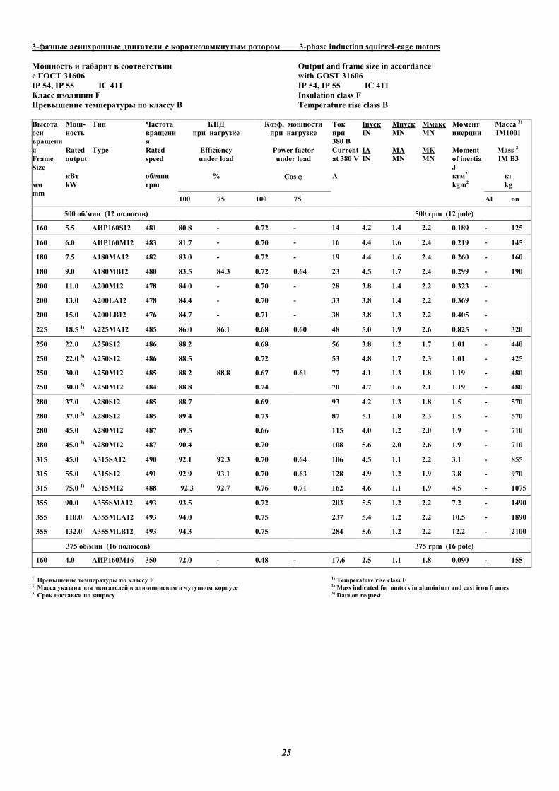
25
3-фазные асинхронные двигатели с короткозамкнутым ротором 3-phase induction squirrel-cage motors
Мощность и габарит в соответствии Output and frame size in accordance
с ГОСТ 31606 with GOST 31606
IP 54, IP 55 IC 411 IP 54, IP 55 IC 411
Класс изоляции F Insulation class F
Превышение температуры по классу В Temperature rise class B
КПД
при нагрузке
Efficiency
under load
%
Коэф. мощности
при нагрузке
Power factor
under load
Cos ϕ
Масса 2)
IM1001
Mass 2)
IM B3
кг
kg
Высота
оси
вращени
я
Frame
Size
мм
mm
Мощ-
ность
Rated
output
кВт
kW
Тип
Type
Частота
вращени
я
Rated
speed
об/мин
rpm
100 75 100 75
Ток
при
380 В
Current
at 380 V
А
Iпуск
IN
IA
IN
Mпуск
MN
MA
MN
Mмакс
MN
MК
MN
Момент
инерции
Moment
of inertia
J
кгм2
kgm2
Al Iron
500 об/мин (12 полюсов) 500 rpm (12 pole)
160 5.5 АИР160S12 481 80.8 - 0.72 - 14 4.2 1.4 2.2 0.189 - 125
160 6.0 АИР160М12 483 81.7 - 0.70 - 16 4.4 1.6 2.4 0.219 - 145
180 7.5 A180MA12 482 83.0 - 0.72 - 19 4.4 1.6 2.4 0.260 - 160
180 9.0 A180MB12 480 83.5 84.3 0.72 0.64 23 4.5 1.7 2.4 0.299 - 190
200 11.0 A200M12 478 84.0 - 0.70 - 28 3.8 1.4 2.2 0.323 -
200 13.0 A200LA12 478 84.4 - 0.70 - 33 3.8 1.4 2.2 0.369 -
200 15.0 A200LB12 476 84.7 - 0.71 - 38 3.8 1.3 2.2 0.405 -
225 18.5 1) A225MА12 485 86.0 86.1 0.68 0.60 48 5.0 1.9 2.6 0.825 - 320
250 22.0 А250S12 486 88.2 0.68 56 3.8 1.2 1.7 1.01 - 440
250 22.0 3) А250S12 486 88.5 0.72 53 4.8 1.7 2.3 1.01 - 425
250 30.0 А250М12 485 88.2 88.8 0.67 0.61 77 4.1 1.3 1.8 1.19 - 480
250 30.0 3) А250М12 484 88.8 0.74 70 4.7 1.6 2.1 1.19 - 480
280 37.0 А280S12 485 88.7 0.69 93 4.2 1.3 1.8 1.5 - 570
280 37.0 3) А280S12 485 89.4 0.73 87 5.1 1.8 2.3 1.5 - 570
280 45.0 А280М12 487 89.5 0.66 115 4.0 1.2 2.0 1.9 - 710
280 45.0 3) А280М12 487 90.4 0.70 108 5.6 2.0 2.6 1.9 - 710
315 45.0 A315SА12 490 92.1 92.3 0.70 0.64 106 4.5 1.1 2.2 3.1 - 855
315 55.0 A315S12 491 92.9 93.1 0.70 0.63 128 4.9 1.2 1.9 3.8 - 970
315 75.0 1) A315M12 488 92.3 92.7 0.76 0.71 162 4.6 1.1 1.9 4.5 - 1075
355 90.0 A355SMA12 493 93.5 0.72 203 5.5 1.2 2.2 7.2 - 1490
355 110.0 A355МLA12 493 94.0 0.75 237 5.4 1.2 2.2 10.5 - 1890
355 132.0 A355MLB12 493 94.3 0.75 284 5.6 1.2 2.2 12.2 - 2100
375 об/мин (16 полюсов) 375 rpm (16 pole)
160 4.0 АИР160М16 350 72.0 - 0.48 - 17.6 2.5 1.1 1.8 0.090 - 155
1) Превышение температуры по классу F 1) Temperature rise class F 2) Масса указана для двигателей в алюминиевом и чугунном корпусе 2) Mass indicated for motors in aluminium and cast iron frames 3) Срок поставки по запросу 3) Data on request
26
����������� ���������� �� � �� ����� ���������
Technical features of multiple-speed motors
������������� ������ ������� ��������� �� ��� � -
����������� � ������� ��� �������.
���������� ���������� �� �� � �������:
� ��������������� � ����� ����������� �����
�� � ��������,
� ��� ��� - �� ��� �� ���������� ������ ���� � �����-
������� �������. ���� ������� ���������� � ������
��� � �����.
�� �������� (�������� ������) ������������� ���-
��� ������� ��� ������ �� �� �� �:
� � ��������� ������� �������� �� ����. ���������� ��
����� ��, ����� �������� ������ � ������ ��� ����-
��� ��������.
� � ������������ ��������������. ���������� �� ���-
�� ��, ����� �������� ������ �������� � ��� ��������
����������� �� ������� �������� (���������, �����).
��� ������ ������� �� ��������.
�����!�� ��������� ������ ������� ����������� ���-
����� �� ��� �� �������� �������������� �� ������� �-
��������� ������ ������� �������. "�� ����������� �-
���� ������ ������� ����� ��� ����� ����� ��������
(���������� ��������) ����� ���� �������� ��� ����-
��� ��������.
���� ����
��� �� � ������� � � �� ����� � ���� � ������
����� ��� ������� ��������� �� ����� �� ��� ���������
- 3000 � 1500 ��/��� � ������� �������� 53 #*�. ��������
�� � ���������� ���:
- 1500 ��/��� � 1500 (��/���)*53 (#*�)/9550=8,3 � �;
- 3000 ��/��� � 3000 (��/���)*53 (#*�)/9550=16,6 � �;
"�� ������ �������� ������� ������ ������� � �����-
��� ������� 4/2 (3000/1500��/���). �� �����! ������
������ ������� $%&160�4/2 � ���������������� ���-
������ 17� � ��� 2950��/���. '� ��������, ����� ��-
������ ������ ������� 17(� �)/2950(��/���)*9550=55 #*�,
��� �� 4% ����( ������ �������� ����� ���� ��������.
��� � ��� 1475 ��/��� ������� �� � �������� � �������
��������� �� ���� 1475(��/���)*53(#*�)/9550=8,2� �, ���
��������� 59% �� ���������������� ����������� �����-
��� (14 � �).
#�� � � ���������������� �������� ������ ������� ��
��� �������� ����� ��� ����( ��� ����� ��������
�������� �������� ��� �������������� ��������� ����-
���.
������������� ������ ������� ���������� �� �����-
���� 380, 400, 660 � 690 � ������ ��� 50 )!.
�� ��������� ��������� ������� ����� ��� ������
�� ���� ���� ���� ��������� � ������� ���.
� ��� ���� ������ � ��� ���� ��� � ����� �����
�� � �� ����� ����� ��������, ������������ �
��� � ����� ��� � � ��� � � �� ������ 71-355
��.
Multiple-speed electric motors are made on base of one-speed
ones with changing winding schemes. .
In practice two types of windings are used:
� pole-changing � which have electrical connection between
poles,
� separate � on each pole direction its own one-speed wind-
ing is put. Such windings are not bound to each other electri-
cally.
By power (rotational moment) multi-speed electric motors are
divided on two types:
� with constant load moment on the shaft. They used for
drives, the load moment of which do not change by rotation
change.
� with fan characteristic. They used for drives, which load
moment varies in quadratic dependence of rotation changes
(fans, pumps).
Selection of the motor according to the power.
The rated power for each speed of the multiple-speed electric
motor fixed in motor characteristics tables. The data are regu-
lated in according with allowable stator winding overheating.
In order to choose the right motor it is necessary to know the
load moment (power consumption) of drive mechanism in
working rotations.
Calculation example
Drive mechanism with constant load moment
Drive mechanism is calculated for work on two speeds - 3000
and 1500 rpm with load moment 53 N*m. The power will be:
- 1500 rpm � 1500 (rpm)*53 (N*m)/9550=8,3 kW;
- 3000 rpm � 3000 (rpm)*53 (N*m)/9550=16,6 kW;
For this mechanism you should use electric motor with pole
combination 4/2 (3000/1500 rpm). According to the table we
choose the electric motor $IR160�4/2 with regulated power
17 kW by 2950 rpm. Consequently, motor load moment
17(kW)/2950(rpm)*9550=55 N*m, that for 4% more than load
moment of drive mechanism. So by 1475 rpm motor will work
with useful power on shaft 1475(rpm)*53(N*m)/9550= 8,2kW,
that is 59% from regulated rated power (14 kW).
Conclusion � regulated motor power on all rotations should be
higher or equal to the rated load power by the appropriate rotat-
ing speeds.
Multiple-speed electric motors are made for voltages 380, 400,
660 and 690 V and power frequency 50 Hz.
Upon the customer request it is possible to make the motors for
other standard voltages and power frequency.
Upon the customer request it is possible to produce any
multiple-speed electric motors with shaft height 71-355mm,
which are absent in this catalogue chapter.
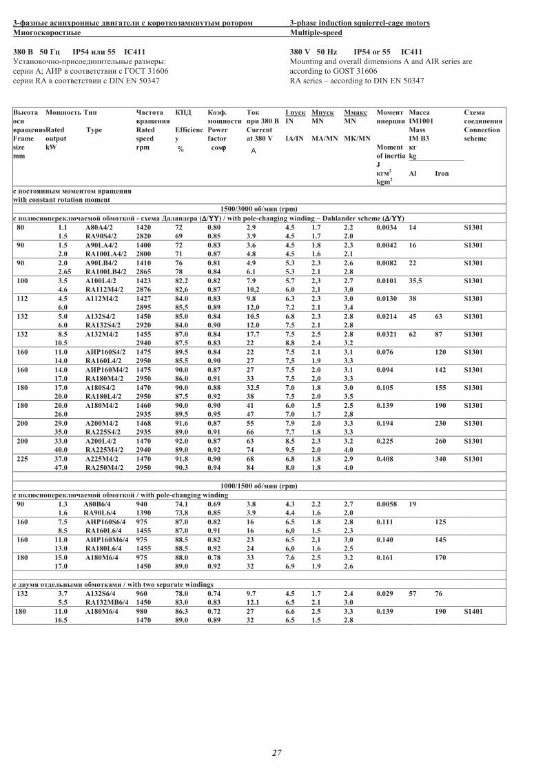
27
3-������ ��������� � ������� � ��������������� ����� 3-phase induction squierrel-cage motors
�������������� Multiple-speed
380 � 50 �� IP54 ��� 55 IC411 380 V 50 Hz IP54 or 55 IC411
�����������-���� ���������� �����: Mounting and overall dimensions A and AIR series are
���� �; ��� � ������������ � ���� 31606 according to GOST 31606
���� RA � ������������ � DIN EN 50347 RA series � according to DIN EN 50347
������
���
������
Frame
size
mm
��������
Rated
output
kW
���
Type
�������
������
Rated
speed
rpm
��
Efficienc
y
%
��!�.
��������
Power
factor
cosϕϕϕϕ
���
�� 380 �
Current
at 380 V
A
I ����
IN
IA/IN
M����
MN
MA/MN
M����
MN
M�/MN
������
������
Moment
of inertia
J
���2
kgm2
�����
IM1001
Mass
IM B3
��
kg
"���
����������
Connection
scheme
Al Iron
� ���������� �������� ������
with constant rotation moment
1500/3000 �#/��� (rpm)
c ���$��������$%����& �#�����& - ���� ������� (∆∆∆∆/ΥΥΥΥΥΥΥΥ) / with pole-changing winding � Dahlander scheme (∆∆∆∆/ΥΥΥΥΥΥΥΥ)
80 1.1
1.5
A80A4/2
RA90S4/2
1420
2820
72
69
0.80
0.85
2.9
3.9
4.5
4.5
1.7
1.7
2.2
2.0
0.0034 14 S1301
90 1.5
2.0
A90LA4/2
RA100LA4/2
1400
2800
72
71
0.83
0.87
3.6
4.8
4.5
4.5
1.8
1.6
2.3
2.1
0.0042 16 S1301
90 2.0
2.65
A90LB4/2
RA100LB4/2
1410
2865
76
78
0.81
0.84
4.9
6.1
5.3
5.3
2.3
2.1
2.6
2.8
0.0082 22 S1301
100 3.5
4.6
A100L4/2
RA112M4/2
1423
2876
82.2
82,6
0.82
0.87
7.9
10,2
5.7
6.0
2,3
2,1
2.7
3,0
0.0101 35,5 S1301
112 4.5
6,0
A112M4/2 1427
2895
84.0
85,5
0.83
0.89
9.8
12,0
6.3
7.2
2.3
2.1
3,0
3,4
0.0130 38 S1301
132 5.0
6.0
A132S4/2
RA132S4/2
1450
2920
85.0
84.0
0.84
0.90
10.5
12.0
6.8
7.5
2.3
2.1
2.8
2.8
0.0214 45 63 S1301
132 8.5
10.5
A132M4/2 1455
2940
87.0
87.5
0.84
0.83
17.7
22
7.5
8.8
2.5
2.4
2.8
3.2
0.0321 62 87 S1301
160 11.0
14.0
'()160S4/2
RA160L4/2
1475
2950
89.5
85.5
0.84
0.90
22
27
7.5
7,5
2.1
1.9
3.1
3.3
0.076 120 S1301
160 14.0
17.0
'()160M4/2
RA180M4/2
1475
2950
90.0
86.0
0.87
0.91
27
33
7.5
7.5
2.0
2,0
3.1
3.3
0.094 142 S1301
180 17.0
20.0
'180S4/2
RA180L4/2
1470
2950
90.0
87.5
0.88
0.92
32.5
38
7.0
7.5
1.8
2.0
3.0
3.5
0.105 155 S1301
180 20.0
26.0
'180�4/2 1460
2935
90.0
89.5
0.90
0.95
41
47
6.0
7.0
1.5
1.7
2.5
2,8
0.139 190 S1301
200 29.0
35.0
'200M4/2
RA225S4/2
1468
2935
91.6
89.0
0.87
0.91
55
66
7.9
7.7
2.0
1.8
3.3
3.3
0.194 230 S1301
200 33.0
40.0
'200L4/2
RA225M4/2
1470
2940
92.0
89.0
0.87
0.92
63
74
8.5
9.5
2.3
2.0
3.2
4.0
0.225 260 S1301
225 37.0
47.0
'225�4/2
RA250M4/2
1470
2950
91.8
90.3
0.90
0.94
68
84
6.8
8.0
1.8
1.8
2.9
4.0
0.408 340 S1301
1000/1500 �#/��� (rpm)
c ���$��������$%����& �#�����& / with pole-changing winding
90 1.3
1.6
'80B6/4
RA90L6/4
940
1390
74.1
73.8
0.69
0.85
3.8
3.9
4.3
4.4
2.2
1.6
2.7
2.0
0.0058 19
160 7.5
8.5
'()160S6/4
RA160L6/4
975
1455
87.0
87.0
0.82
0.91
16
16
6.5
6,0
1.8
1.5
2.8
2.3
0.111 125
160 11.0
13.0
'()160M6/4
RA180L6/4
975
1455
88.5
88.5
0.82
0.92
23
24
6.5
6,0
2,1
1.6
3,0
2.5
0.140 145
180 15.0
17.0
A180M6/4
975
1450
88.0
89.0
0.78
0.92
33
32
7.6
6.9
2.5
1.9
3.2
2.6
0.161 170
c � ��� ���������� �#������� / with two separate windings
132 3.7
5.5
'132S6/4
RA132MB6/4
960
1450
78.0
83.0
0.74
0.83
9.7
12.1
4.5
6.5
1.7
2.1
2.4
3.0
0.029 57 76
180 11.0
16.5
'180M6/4 980
1470
86.3
89.0
0.72
0.89
27
32
6.6
6.5
2.5
1.5
3.3
2.8
0.139 190 S1401
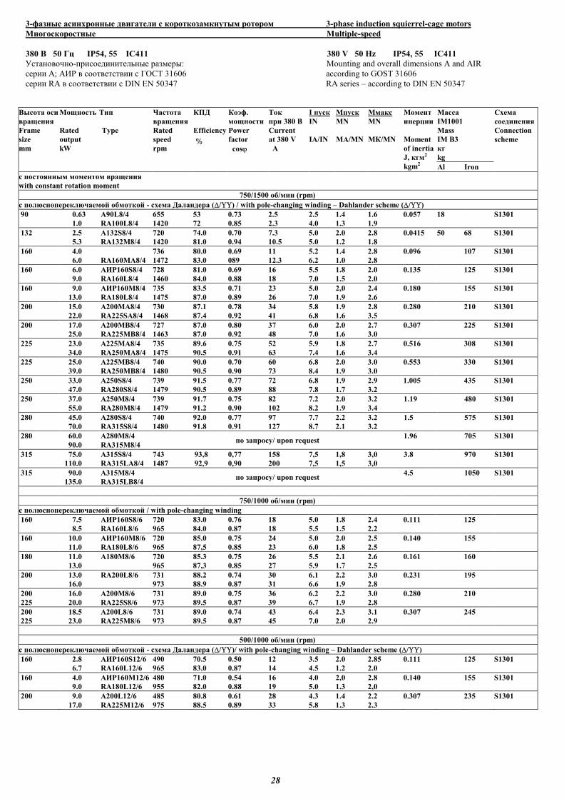
28
3-фазные асинхронные двигатели с короткозамкнутым ротором 3-phase induction squierrel-cage motors
Многоскоростные Multiple-speed
380 В 50 Гц IP54, 55 IC411 380 V 50 Hz IP54, 55 IC411
Установочно-присоединительные размеры: Mounting and overall dimensions A and AIR
серии А; АИР в соответствии с ГОСТ 31606 according to GOST 31606
серии RA в соответствии с DIN EN 50347 RA series – according to DIN EN 50347
Масса
IM1001
Mass
IM B3
кг
kg
Высота оси
вращения
Frame
size
mm
Мощность
Rated
output
kW
Тип
Type
Частота
вращения
Rated
speed
rpm
КПД
Efficiency
%
Коэф.
мощности
Power
factor
cosϕ
Ток
при 380 В
Current
at 380 V
A
I пуск
IN
IA/IN
Mпуск
MN
MA/MN
Mмакс
MN
MК/MN
Момент
инерции
Moment
of inertia
J, кгм2
kgm2 Al Iron
Схема
соединения
Connection
scheme
с постоянным моментом вращения
with constant rotation moment
750/1500 об/мин (rpm)
c полюснопереключаемой обмоткой - схема Даландера (∆/ΥΥ) / with pole-changing winding – Dahlander scheme (∆/ΥΥ)
90 0.63
1.0
A90L8/4
RA100L8/4
655
1420
53
72
0.73
0.85
2.5
2.3
2.5
4.0
1.4
1.3
1.6
1.9
0.057 18 S1301
132 2.5
5.3
A132S8/4
RA132M8/4
720
1420
74.0
81.0
0.70
0.94
7.3
10.5
5.0
5.0
2.0
1.2
2.8
1.8
0.0415 50 68 S1301
160 4.0
6.0
RA160MA8/4
736
1472
80.0
83.0
0.69
089
11
12.3
5.2
6.2
1.4
1.0
2.8
2.8
0.096 107 S1301
160 6.0
9.0
АИР160S8/4
RA160L8/4
728
1460
81.0
84.0
0.69
0.88
16
18
5.5
7.0
1.8
1.5
2.0
2.0
0.135 125 S1301
160 9.0
13.0
АИР160M8/4
RA180L8/4
735
1475
83.5
87.0
0.71
0.89
23
26
5.0
7.0
2,0
1.9
2.4
2.6
0.180 155 S1301
200
15.0
22.0
А200MA8/4
RA225SA8/4
730
1468
87.1
87.4
0.78
0.92
34
41
5.8
6.8
1.9
1.6
2.8
3.5
0.280 210 S1301
200 17.0
25.0
А200MB8/4
RA225MB8/4
727
1463
87.0
87.0
0.80
0.92
37
48
6.0
7.0
2.0
1.6
2.7
3.0
0.307 225 S1301
225
23.0
34.0
А225MA8/4
RA250MA8/4
735
1475
89.6
90.5
0.75
0.91
52
63
5.9
7.4
1.8
1.6
2.7
3.4
0.516 308 S1301
225
25.0
39.0
А225MB8/4
RA250MB8/4
740
1480
90.0
90.5
0.70
0.90
60
73
6.8
8.4
2.0
1.9
3.0
3.0
0.553 330 S1301
250
33.0
47.0
А250S8/4
RA280S8/4
739
1479
91.5
90.5
0.77
0.89
72
88
6.8
7.8
1.9
1.7
2.9
3.2
1.005 435 S1301
250
37.0
55.0
А250M8/4
RA280M8/4
739
1479
91.7
91.2
0.75
0.90
82
102
7.2
8.2
2.0
1.9
3.2
3.4
1.19 480 S1301
280
45.0
70.0
А280S8/4
RA315S8/4
740
1480
92.0
91.8
0.77
0.91
97
127
7.7
8.7
2.2
2.1
3.2
3.2
1.5 575 S1301
280
60.0
90.0
А280M8/4
RA315M8/4 по запросу/ upon request
1.96 705 S1301
315
75.0
110.0
А315S8/4
RA315LA8/4
743
1487
93,8
92,9
0,77
0,90
158
200
7,5
7,5
1,8
1,5
3,0
3,0
3.8 970 S1301
315
90.0
135.0
А315M8/4
RA315LB8/4 по запросу/ upon request
4.5 1050 S1301
750/1000 об/мин (rpm)
c полюснопереключаемой обмоткой / with pole-changing winding
160 7.5
8.5
АИР160S8/6
RA160L8/6
720
965
83.0
84.0
0.76
0.87
18
18
5.0
5.5
1.8
1.5
2.4
2.2
0.111 125
160 10.0
11.0
АИР160M8/6
RA180L8/6
720
965
85.0
87,5
0.75
0.85
24
23
5.0
6.0
2.0
1.8
2.5
2.5
0.140 155
180 11.0
13.0
А180M8/6
720
965
85.3
87,3
0.75
0.85
26
27
5.5
5.9
2.1
1.7
2.6
2.5
0.161 160
200 13.0
16.0
RA200L8/6 731
973
88.2
88.9
0.74
0.87
30
31
6.1
6.6
2.2
1.9
3.0
2.8
0.231 195
200
225
16.0
20.0
А200М8/6
RA225S8/6
731
973
89.0
89.5
0.75
0.87
36
39
6.2
6.7
2.2
1.9
3.0
2.8
0.280 210
200
225
18.5
23.0
А200L8/6
RA225M8/6
731
973
89.0
89.5
0.74
0.87
43
45
6.4
7.0
2.3
2.0
3.1
2.9
0.307 245
500/1000 об/мин (rpm)
c полюснопереключаемой обмоткой - схема Даландера (∆/ΥΥ)/ with pole-changing winding – Dahlander scheme (∆/ΥΥ)
160 2.8
6.7
АИР160S12/6
RA160L12/6
490
965
70.5
83.0
0.50
0.87
12
14
3.5
4.5
2.0
1.2
2.85
2.0
0.111 125 S1301
160 4.0
9.0
АИР160M12/6
RA180L12/6
480
955
71.0
82.0
0.54
0.88
16
19
4.0
5.0
2,0
1.3
2.8
2,0
0.140 155 S1301
200 9.0
17.0
А200L12/6
RA225M12/6
485
975
80.8
88.5
0.61
0.89
28
33
4.3
5.8
1.4
1.3
2.2
2.3
0.307 235 S1301
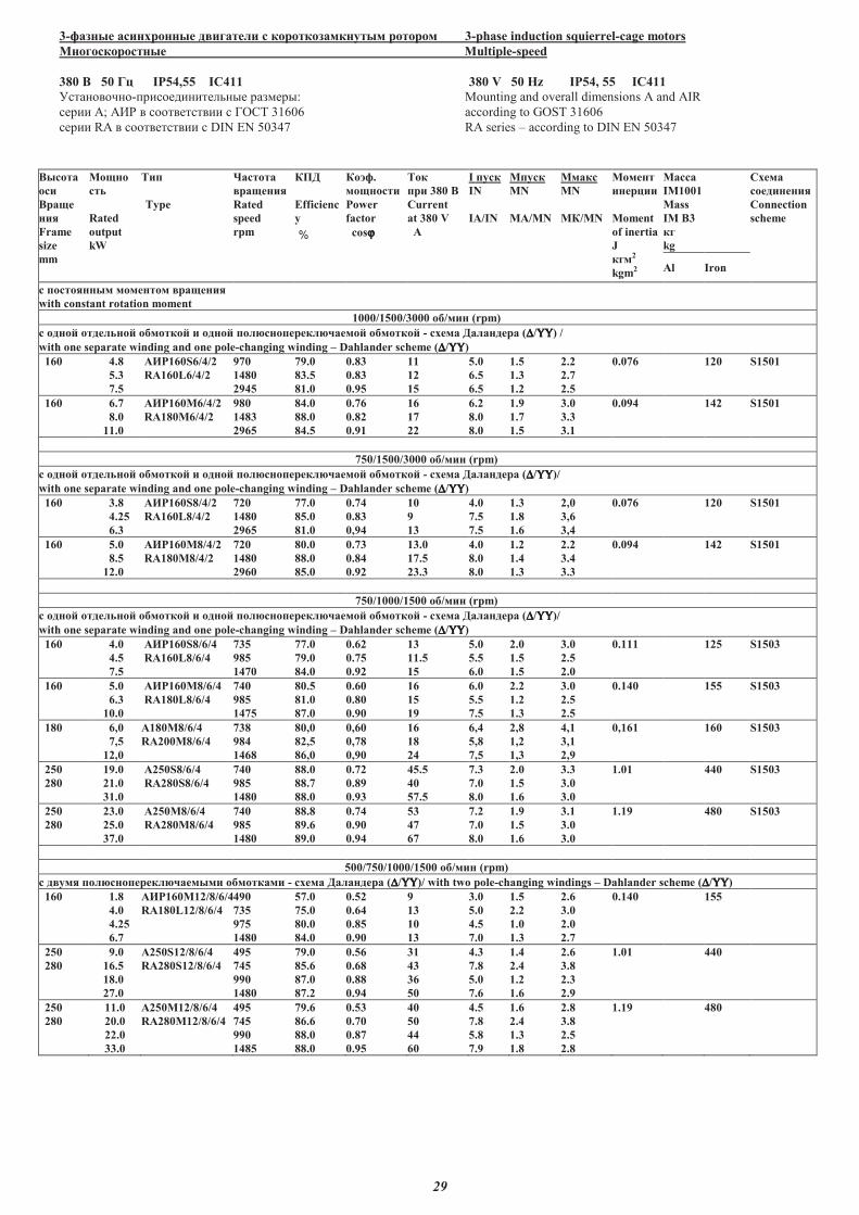
29
3-������ ��������� � ������� � ��������������� ����� 3-phase induction squierrel-cage motors
�������������� Multiple-speed
380 � 50 �� IP54,55 IC411 380 V 50 Hz IP54, 55 IC411
�����������-���� ���������� �����: Mounting and overall dimensions A and AIR
���� �; ��� � ������������ � ���� 31606 according to GOST 31606
���� RA � ������������ � DIN EN 50347 RA series � according to DIN EN 50347
������
���
����
���
Frame
size
mm
�����
���
Rated
output
kW
���
Type
�������
������
Rated
speed
rpm
��
Efficienc
y
%
��!�.
��������
Power
factor
cosϕϕϕϕ
���
�� 380 �
Current
at 380 V
A
I ����
IN
IA/IN
M����
MN
MA/MN
M����
MN
M�/MN
������
������
Moment
of inertia
J
���2
kgm2
�����
IM1001
Mass
IM B3
��
kg
"���
����������
Connection
scheme
Al Iron
� ���������� �������� ������
with constant rotation moment
1000/1500/3000 �#/��� (rpm)
c ����$ ��������$ �#�����$ � ����$ ���%��������%&����$ �#�����$ - ���� ������� (∆∆∆∆/ΥΥΥΥΥΥΥΥ) /
with one separate winding and one pole-changing winding � Dahlander scheme (∆∆∆∆/ΥΥΥΥΥΥΥΥ)
160 4.8
5.3
7.5
'()160S6/4/2
RA160L6/4/2
970
1480
2945
79.0
83.5
81.0
0.83
0.83
0.95
11
12
15
5.0
6.5
6.5
1.5
1.3
1.2
2.2
2.7
2.5
0.076 120 S1501
160 6.7
8.0
11.0
'()160M6/4/2
RA180M6/4/2
980
1483
2965
84.0
88.0
84.5
0.76
0.82
0.91
16
17
22
6.2
8.0
8.0
1.9
1.7
1.5
3.0
3.3
3.1
0.094 142 S1501
750/1500/3000 �#/��� (rpm)
c ����$ ��������$ �#�����$ � ����$ ���%��������%&����$ �#�����$ - ���� ������� (∆∆∆∆/ΥΥΥΥΥΥΥΥ)/
with one separate winding and one pole-changing winding � Dahlander scheme (∆∆∆∆/ΥΥΥΥΥΥΥΥ)
160 3.8
4.25
6.3
'()160S8/4/2
RA160L8/4/2
720
1480
2965
77.0
85.0
81.0
0.74
0.83
0,94
10
9
13
4.0
7.5
7.5
1.3
1.8
1.6
2,0
3,6
3,4
0.076 120 S1501
160 5.0
8.5
12.0
'()160M8/4/2
RA180M8/4/2
720
1480
2960
80.0
88.0
85.0
0.73
0.84
0.92
13.0
17.5
23.3
4.0
8.0
8.0
1.2
1.4
1.3
2.2
3.4
3.3
0.094 142 S1501
750/1000/1500 �#/��� (rpm)
c ����$ ��������$ �#�����$ � ����$ ���%��������%&����$ �#�����$ - ���� ������� (∆∆∆∆/ΥΥΥΥΥΥΥΥ)/
with one separate winding and one pole-changing winding � Dahlander scheme (∆∆∆∆/ΥΥΥΥΥΥΥΥ)
160 4.0
4.5
7.5
'()160S8/6/4
RA160L8/6/4
735
985
1470
77.0
79.0
84.0
0.62
0.75
0.92
13
11.5
15
5.0
5.5
6.0
2.0
1.5
1.5
3.0
2.5
2.0
0.111 125 S1503
160 5.0
6.3
10.0
'()160M8/6/4
RA180L8/6/4
740
985
1475
80.5
81.0
87.0
0.60
0.80
0.90
16
15
19
6.0
5.5
7.5
2.2
1.2
1.3
3.0
2.5
2.5
0.140 155 S1503
180 6,0
7,5
12,0
A180�8/6/4
RA200�8/6/4
738
984
1468
80,0
82,5
86,0
0,60
0,78
0,90
16
18
24
6,4
5,8
7,5
2,8
1,2
1,3
4,1
3,1
2,9
0,161 160 S1503
250
280
19.0
21.0
31.0
A250S8/6/4
RA280S8/6/4
740
985
1480
88.0
88.7
88.0
0.72
0.89
0.93
45.5
40
57.5
7.3
7.0
8.0
2.0
1.5
1.6
3.3
3.0
3.0
1.01 440 S1503
250
280
23.0
25.0
37.0
'250M8/6/4
R'280M8/6/4
740
985
1480
88.8
89.6
89.0
0.74
0.90
0.94
53
47
67
7.2
7.0
8.0
1.9
1.5
1.6
3.1
3.0
3.0
1.19 480 S1503
500/750/1000/1500 �#/��� (rpm)
c � ��� ���%��������%&������ �#������� - ���� ������� (∆∆∆∆/ΥΥΥΥΥΥΥΥ)/ with two pole-changing windings � Dahlander scheme (∆∆∆∆/ΥΥΥΥΥΥΥΥ)
160 1.8
4.0
4.25
6.7
'()160M12/8/6/4
RA180L12/8/6/4
490
735
975
1480
57.0
75.0
80.0
84.0
0.52
0.64
0.85
0.90
9
13
10
13
3.0
5.0
4.5
7.0
1.5
2.2
1.0
1.3
2.6
3.0
2.0
2.7
0.140 155
250
280
9.0
16.5
18.0
27.0
A250S12/8/6/4
RA280S12/8/6/4
495
745
990
1480
79.0
85.6
87.0
87.2
0.56
0.68
0.88
0.94
31
43
36
50
4.3
7.8
5.0
7.6
1.4
2.4
1.2
1.6
2.6
3.8
2.3
2.9
1.01 440
250
280
11.0
20.0
22.0
33.0
'250M12/8/6/4
R'280M12/8/6/4
495
745
990
1485
79.6
86.6
88.0
88.0
0.53
0.70
0.87
0.95
40
50
44
60
4.5
7.8
5.8
7.9
1.6
2.4
1.3
1.8
2.8
3.8
2.5
2.8
1.19 480
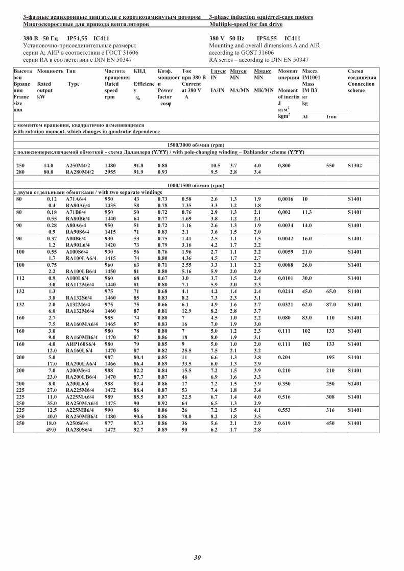
30
3-������ ��������� � ������� � ��������������� ����� 3-phase induction squierrel-cage motors
�������������� ��� �� ��� ��������� Multiple-speed for fan drive
380 � 50 �� IP54,55 IC411 380 V 50 Hz IP54,55 IC411
�����������-���� ���������� �����: Mounting and overall dimensions A and AIR
���� �; ��� � ������������ � ���� 31606 according to GOST 31606
���� RA � ������������ � DIN EN 50347 RA series � according to DIN EN 50347
������
���
����
���
Frame
size
mm
��������
Rated
output
kW
���
Type
�������
������
Rated
speed
rpm
��
Efficienc
y
%
��!�.
�������
�
Power
factor
cosϕϕϕϕ
���
�� 380 �
Current
at 380 V
"
I ����
IN
IA/IN
M����
MN
MA/MN
M����
MN
M�/MN
������
������
Moment
of inertia
J
���2
kgm2
�����
IM1001
Mass
IM B3
��
kg
#���
����������
Connection
scheme
Al Iron
� �������� ������, � �����$�� ������%�����
with rotation moment, which changes in quadratic dependence
1500/3000 �&/��� (rpm)
c ���%��������%$����' �&�����' - ���� ������� (ΥΥΥΥ/ΥΥΥΥΥΥΥΥ) / with pole-changing winding � Dahlander scheme (ΥΥΥΥ/ΥΥΥΥΥΥΥΥ)
250
280
14.0
80.0
"250�4/2
RA280M4/2
1480
2955
91.8
91.9
0.88
0.93
10.5
9.5
3.7
2.8
4.0
3.4
0,800 550 S1302
1000/1500 �&/��� (rpm)
c � ��� ���������� �&������� / with two separate windings
80 0.12
0.4
"71"6/4
RA80A6/4
950
1435
43
58
0.73
0.78
0.58
1.35
2.6
3.3
1.3
1.2
1.9
1.8
0,0016 10 S1401
80 0.18
0.55
"71B6/4
RA80B6/4
950
1440
50
64
0.72
0.77
0.76
1.69
2.9
3.8
1.3
1.2
2.1
2.1
0,002 11.3 S1401
90 0.28
0.9
A80A6/4
RA90S6/4
950
1415
51
71
0.72
0.83
1.16
2.1
2.6
3.6
1.3
1.5
1.9
2.0
0.0034 14.0 S1401
90 0.37
1.2
A80B6/4
RA90L6/4
930
1420
53
73
0.75
0.79
1.41
3.16
2.5
4.2
1.1
1.7
1.5
2.2
0.0042 16.0 S1401
100 0.55
1.7
A100S6/4
RA100LA6/4
930
1415
56
74
0.76
0.80
1.96
4.36
2.7
4.5
1.1
1.7
2.2
2.7
0.0059 21.0 S1401
100 0.75
2.2 RA100LB6/4
960
1450
63
81
0.71
0.80
2.55
5.16
3.3
5.9
1.1
2.0
2.2
2.9
0.0088 26.0 S1401
112 0.9
3.0
A100L6/4
RA112M6/4
960
1440
68
81
0.67
0.80
3.0
7.1
3.7
5.9
1.5
2.0
2.4
2.3
0.0101 30.0 S1401
132 1.3
3.8 RA132S6/4
975
1460
71
85
0.68
0.83
4.1
8.2
4.2
7.3
1.4
2.3
2.4
3.1
0.0214 45.0 65.0 S1401
132 2.0
6.0
A132M6/4
RA132M6/4
975
1460
75
87
0.66
0.81
6.1
12.9
4.9
8.2
1.6
2.8
2.7
3.7
0.0321 62.0 87.0 S1401
160 2.7
7.5 RA160MA6/4
985
1465
74
87
0.80
0.83
7
16
4.5
7.0
1.0
1.9
2.2
3.0
0.080 83.0 110 S1401
160 3.0
9.0 RA160MB6/4
980
1470
78
87
0.80
0.86
7
18
5.0
8.0
1.2
1.9
2.3
3.1
0.111 102 133 S1401
160 4.0
12.0
"()160S6/4
RA160L6/4
980
1470
79
87
0.85
0.82
9
25.5
5.0
7.5
1.0
2.1
2.0
3.2
0.111 102 133 S1401
200 5.0
17.0 RA200LA6/4
987
1466
80.4
86.4
0.85
0.89
11
33.5
6.6
6.0
1.3
1.3
3.8
2.9
0.204 195 S1401
200 7.0
23.0
A200M6/4
RA200LB6/4
988
1470
82.2
87.7
0.84
0.87
15.5
46
7.2
6.9
1.5
1.6
3.9
3.3
0.210 210 S1401
200
225
8.0
27.0
A200L6/4
RA225M6/4
988
1472
83.4
88.4
0.86
0.87
17
53
7.2
7.4
1.5
1.8
3.9
3.4
0.350 250 S1401
225
250
11.0
35.0
"225�"6/4
RA250MA6/4
989
1475
85.5
90
0.87
0.92
22.5
64
6.7
6.5
1.4
1.3
4.0
2.9
0.516 308 S1401
225
250
12.5
40.0
"225��6/4
RA250M�6/4
990
1480
86
90.6
0.86
0.86
26
78.0
7.2
8.2
1.5
1.8
4.1
3.5
0.553 316 S1401
250 18.0
49.0
A250S6/4
RA280S6/4
977
1472
87.3
92.7
0.86
0.89
36
90
5.6
6.2
2.1
1.7
2.9
2.8
0.619 450 S1401
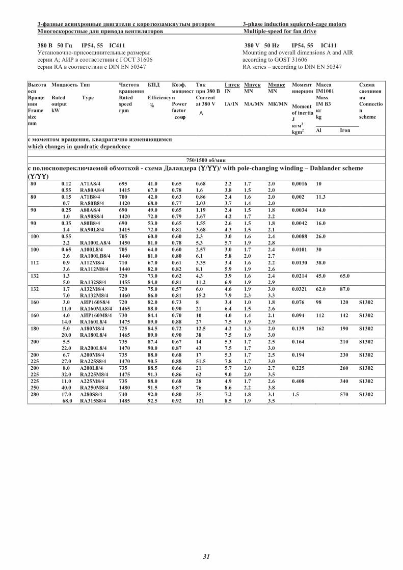
31
3-������ ��������� � ������� � ��������������� ����� 3-phase induction squierrel-cage motors
�������������� ��� �� ��� ��������� Multiple-speed for fan drive
380 � 50 �� IP54, 55 IC411 380 V 50 Hz IP54, 55 IC411
�����������-���� ���������� �����: Mounting and overall dimensions A and AIR
���� �; ��� � ������������ � ���� 31606 according to GOST 31606
���� RA � ������������ � DIN EN 50347 RA series � according to DIN EN 50347 �
������
���
����
���
Frame
size
mm
��������
Rated
output
kW
���
Type
�������
������
Rated
speed
rpm
��
Efficiency
%
��!�.
�������
�
Power
factor
cosϕϕϕϕ
���
�� 380 �
Current
at 380 V
A
I ����
IN
IA/IN
M����
MN
MA/MN
M����
MN
M�/MN
������
������
Moment
of inertia
J
���2
kgm2
�����
IM1001
Mass
IM B3
��
kg
"���
��������
��
Connectio
n
scheme
Al Iron
� �������� ������, � �����#�� ������$�����
which changes in quadratic dependence
750/1500 �%/���
c ���$��������$#����& �%�����& - ���� ������� (ΥΥΥΥ/ΥΥΥΥΥΥΥΥ)/ with pole-changing winding � Dahlander scheme
(ΥΥΥΥ/ΥΥΥΥΥΥΥΥ) 80 0.12
0.55
A71A8/4
RA80A8/4
695
1415
41.0
67.0
0.65
0.78
0.68
1.6
2.2
3.8
1.7
1.5
2.0
2.0
0,0016 10
80 0.15
0.7
A71B8/4
RA80B8/4
700
1420
42.0
68.0
0.63
0.77
0.86
2.03
2.4
3.7
1.6
1.4
2.0
2.0
0,002 11.3
90 0.25
1.0
A80A8/4
RA90S8/4
690
1420
49.0
72.0
0.65
0.79
1.19
2.67
2.4
4.2
1.5
1.7
1.8
2.2
0.0034 14.0
90 0.35
1.4
A80B8/4
RA90L8/4
690
1415
53.0
72.0
0.65
0.81
1.55
3.68
2.6
4.3
1.5
1.5
1.8
2.1
0.0042 16.0
100 0.55
2.2 RA100LA8/4
705
1450
60.0
81.0
0.60
0.78
2.3
5.3
3.0
5.7
1.6
1.9
2.4
2.8
0.0088 26.0
100 0.65
2.6
A100L8/4
RA100LB8/4
705
1440
64.0
81.0
0.60
0.80
2.57
6.1
3.0
5.8
1.7
2.0
2.4
2.7
0.0101 30
112 0.9
3.6
A112M8/4
RA112M8/4
710
1440
67.0
82.0
0.61
0.82
3.35
8.1
3.4
5.9
1.6
1.9
2.2
2.6
0.0130 38.0
132 1.3
5.0 RA132S8/4
720
1455
73.0
84.0
0.62
0.81
4.3
11.2
3.9
6.9
1.6
1.9
2.4
2.9
0.0214 45.0 65.0
132 1.7
7.0
A132M8/4
RA132M8/4
720
1460
75.0
86.0
0.57
0.81
6.0
15.2
4.6
7.9
1.9
2.3
3.0
3.3
0.0321 62.0 87.0
160 3.0
11.0
'()160S8/4
RA160MA8/4
720
1465
82.0
88.0
0.73
0.90
8
21
3.4
6.4
1.0
1.5
1.8
2.6
0.076 98 120 S1302
160 4.0
14.0
'()160�8/4
RA160L8/4
730
1475
84.4
89.0
0.70
0.88
10
27
4.0
7.5
1.4
1.9
2.1
2.9
0.094 112 142 S1302
180 5.0
20.0
'180�8/4
RA180L8/4
725
1465
84.5
89.0
0.72
0.90
12.5
38
4.2
7.5
1.3
1.9
2.0
3.0
0.139 162 190 S1302
200 5.5
22.0 RA200L8/4
735
1470
87.4
90.0
0.67
0.87
14
43
5.3
7.5
1.7
1.7
2.5
3.0
0.164 210 S1302
200
225
6.7
27.0
A200M8/4
RA225S8/4
735
1470
88.0
90.5
0.68
0.88
17
51.5
5.3
7.8
1.7
1.7
2.5
3.0
0.194 230 S1302
200
225
8.0
32.0
A200L8/4
RA225M8/4
735
1475
88.5
91.3
0.66
0.86
21
62
5.7
9.0
2.0
2.0
2.7
3.5
0.225 260 S1302
225
250
11.0
40.0
'225�8/4
RA250M8/4
735
1480
88.0
91.5
0.68
0.87
28
76
4.9
8.6
1.7
2.2
2.6
3.8
0.408 340 S1302
280 17.0
68.0
A280S8/4
RA315S8/4
740
1485
92.0
92.5
0.80
0.92
35
121
7.2
8.5
1.8
1.9
3.1
3.5
1.5 570 S1302
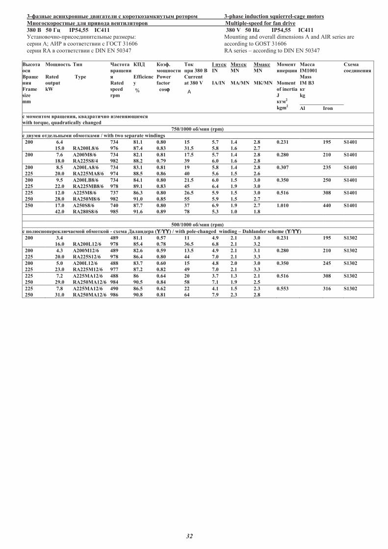
32
3-������ ��������� � ������� � ��������������� ����� 3-phase induction squierrel-cage motors
�������������� ��� �� ��� ��������� Multiple-speed for fan drive
380 � 50 �� IP54,55 IC411 380 V 50 Hz IP54,55 IC411
�����������-���� ���������� �����: Mounting and overall dimensions A and AIR series are
���� �; ��� � ������������ � ���� 31606 according to GOST 31606
���� RA � ������������ � DIN EN 50347 RA series � according to DIN EN 50347
������
���
����
���
Frame
size
mm
��������
Rated
output
kW
���
Type
�������
�����
�
Rated
speed
rpm
��
Efficienc
y
%
��!�.
��������
Power
factor
cosϕϕϕϕ
���
�� 380 �
Current
at 380 V
A
I ����
IN
IA/IN
M����
MN
MA/MN
M����
MN
M�/MN
������
������
Moment
of inertia
J
���2
kgm2
�����
IM1001
Mass
IM B3
��
kg
"���
����������
Al Iron
� �������� ������, � �����#�� ������$�����
with torque, quadratically changed
750/1000 �%/��� (rpm)
c � ��� ���������� �%������� / with two separate windings
200 6.4
15.0 RA200L8/6
734
976
81.1
87.4
0.80
0.83
15
31.5
5.7
5.8
1.4
1.6
2.8
2.7
0.231 195 S1401
200 7.6
18.0
A200�8/6
RA225S8/4
734
982
82.1
88.2
0.81
0.79
17.5
39
5.7
6.0
1.4
1.6
2.8
2.8
0.280 210 S1401
200
225
8.5
20.0
A200LA8/6
RA225MA8/6
734
974
83.1
88.5
0.81
0.86
19
40
5.8
5.6
1.4
1.5
2.8
2.6
0.307 235 S1401
200
225
9.5
22.0
A200LB8/6
RA225MB8/6
734
978
84.1
89.1
0.80
0.83
21.5
45
6.0
6.4
1.5
1.9
3.0
3.0
0.350 250 S1401
225
250
12.0
28.0
&225�8/6
RA250M8/6
737
982
86.3
91.0
0.80
0.85
26.5
55
5.9
5.9
1.5
1.5
3.0
2.7
0.516 308 S1401
250 17.0
42.0
A250S8/6
RA280S8/6
740
985
87.7
91.6
0.80
0.89
37
78
6.9
5.3
1.9
1.0
2.7
1.8
1.010 440 S1401
500/1000 �%/��� (rpm)
c ���$��������$#����' �%�����' - ���� ������� (ΥΥΥΥ/ΥΥΥΥΥΥΥΥ) / with pole-changed winding � Dahlander scheme (ΥΥΥΥ/ΥΥΥΥΥΥΥΥ)
200 3.4
16.0 RA200L12/6
489
978
81.1
85.4
0.57
0.78
11
36.5
4.9
6.8
2.1
2.1
3.0
3.2
0.231 195 S1302
200
225
4.3
20.0
A200M12/6
RA225S12/6
489
978
82.6
86.4
0.59
0.80
13.5
44
4.9
7.0
2.1
2.1
3.1
3.3
0.280 210 S1302
200
225
5.0
23.0
A200L12/6
RA225M12/6
488
977
83.7
87.2
0.60
0.82
15
49
4.8
7.0
2.0
2.1
3.0
3.3
0.350 245 S1302
225
250
7.2
29.0
&225�A12/6
RA250MA12/6
488
984
86
90.5
0.64
0.84
20
58
3.7
7.1
1.3
1.9
2.1
2.5
0.516 308 S1302
225
250
7.8
31.0
&225�A12/6
RA250MA12/6
490
986
86.5
90.8
0.62
0.81
22
64
4.1
7.9
1.5
2.3
2.3
2.8
0.553 316 S1302
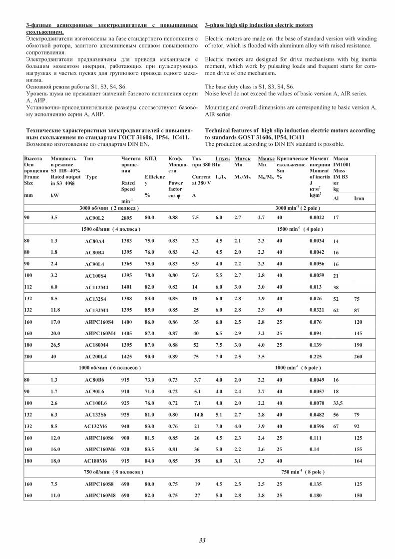
33
3-������ ��������� � ����������� � � ����������
��� �������.
������������� �������� �� �� � ������������ �������� �
�������� ������, ������ �������� ������ ����������
����������.
������������� ������ ������ ��� ����� ����� �� �
������ �������� ����, ��������� �� ����������
����� ��� ������ ������ ��� ��������� ����� ������ ����-
� ��.
������� ���� ������ S1, S3, S4, S6.
����� ���� �� �������� ������ �� ���� �������� ���
!, !"#.
���������-�������������� �� ���� ����������� �� ��-
�� �������� ��� !, !"#.
3-phase high slip induction electric motors
Electric motors are made on the base of standard version with winding
of rotor, which is flooded with aluminum alloy with raised resistance.
Electric motors are designed for drive mechanisms with big inertia
moment, which work by pulsating loads and frequent starts for com-
mon drive of one mechanism.
The base duty class is S1, S3, S4, S6.
Noise level do not exceed the values of basic version A, AIR series.
Mounting and overall dimensions are corresponding to basic version A,
AIR series.
���������� ����������� � ����������� �� � �������-
��� ��� ������� �� ��������� ���� 31606, IP54, IC411.
$� ����� �������� �� ���������� DIN EN.
Technical features of high slip induction electric motors according
to standards GOST 31606, IP54, IC411
The production according to DIN EN standard is possible.
������
���
������
Frame
Size
mm
!�������
� �����
S3 "�=40%
Rated output
in S3 40%%%%
kW
���
Type
#������
����-
��
Rated
Speed
min-1
$"%
Effi�ienc
y
%
$���.
!����-
���
Power
factor
cos ϕϕϕϕ
���
�� 380 �
Current
at 380 V
&
I �'��
I�
IA/IN
M�'��
M�
MA/MN
M����
M�
M$/MN
$���������
��� ������
Sm
%
!�����
���(��
Moment
of inertia
J
���2
kgm2
!����
IM1001
Mass
IM B3
��
kg
Al Iron
3000 �)/��� ( 2 �� *�� ) 3000 min-1 ( 2 pole )
90 3,5 AC90L2 2895 80.0 0.88 7.5 6.0 2.7 2.7 40 0.0022 17
1500 �)/��� ( 4 �� *�� ) 1500 min-1 ( 4 pole )
80 1.3 AC80&4 1383 75.0 0.83 3.2 4.5 2.1 2.3 40 0.0034 14
80 1.8 &�80�4 1395 76.0 0.83 4.3 4.5 2.0 2.3 40 0.0042 16
90 2.4 &�90L4 1365 75.0 0.83 5.9 4.0 2.2 2.3 40 0.0056 16
100 3.2 AC100S4 1395 78.0 0.80 7.6 5.5 2.7 2.8 40 0.0059 21
112 6.0 AC112M4 1401 82.0 0.82 14 6.0 3.0 3.0 40 0.013 38
132 8.5 AC132S4 1388 83.0 0.85 18 6.0 2.8 2.9 40 0.026 52 75
132 11.8 AC132M4 1395 85.0 0.85 25 6.0 2.8 2.9 40 0.0321 62 87
160 17.0 A+,C160S4 1400 86.0 0.86 35 6.0 2.5 2.8 25 0.076 120
160 20.0 A+,C160M4 1405 87.0 0.87 40 6.5 2.9 3.2 25 0.094 145
180 26,5 &�180!4 1395 87.0 0.88 52 7.5 3.0 4.0 25 0.139 190
200 40 &�200L4 1425 90.0 0.89 75 7.0 2.5 3.5 0.225 260
1000 �)/��� ( 6 �� *��� ) 1000 min-1 ( 6 pole )
80 1.3 &�80�6 915 73.0 0.73 3.7 4.0 2.0 2.2 40 0.0049 16
90 1.7 &�90L6 910 71.0 0.72 5.1 4.0 2.4 2.7 40 0.0057 18
100 2.6 AC100L6 925 76.0 0.72 7.1 4.0 2.0 2.2 40 0.0070 33,5
132 6.3 &�132S6 925 81.0 0.80 14.8 5.1 2.7 2.8 40 0.0482 56 79
132 8.5 &�132M6 940 83.0 0.76 21 7.0 4.0 3.9 40 0.0596 67 92
160 12.0 &+,C160S6 900 81.5 0.85 26 4.5 2.3 2.4 25 0.111 125
160 16.0 &+,C160M6 920 83.5 0.81 36 5.0 2.2 2.6 25 0.14 155
180 18,0 &�180!6 915 84.0 0,85 38 6,0 3,1 3,3 40 164
750 �)/��� ( 8 �� *��� ) 750 min-1 ( 8 pole )
160 7.5 &+,C160S8 690 80.0 0.75 19 4.5 2.5 2.5 25 0.135 125
160 11.0 &+,C160M8 690 82.0 0.75 27 5.0 2.8 2.8 25 0.180 150
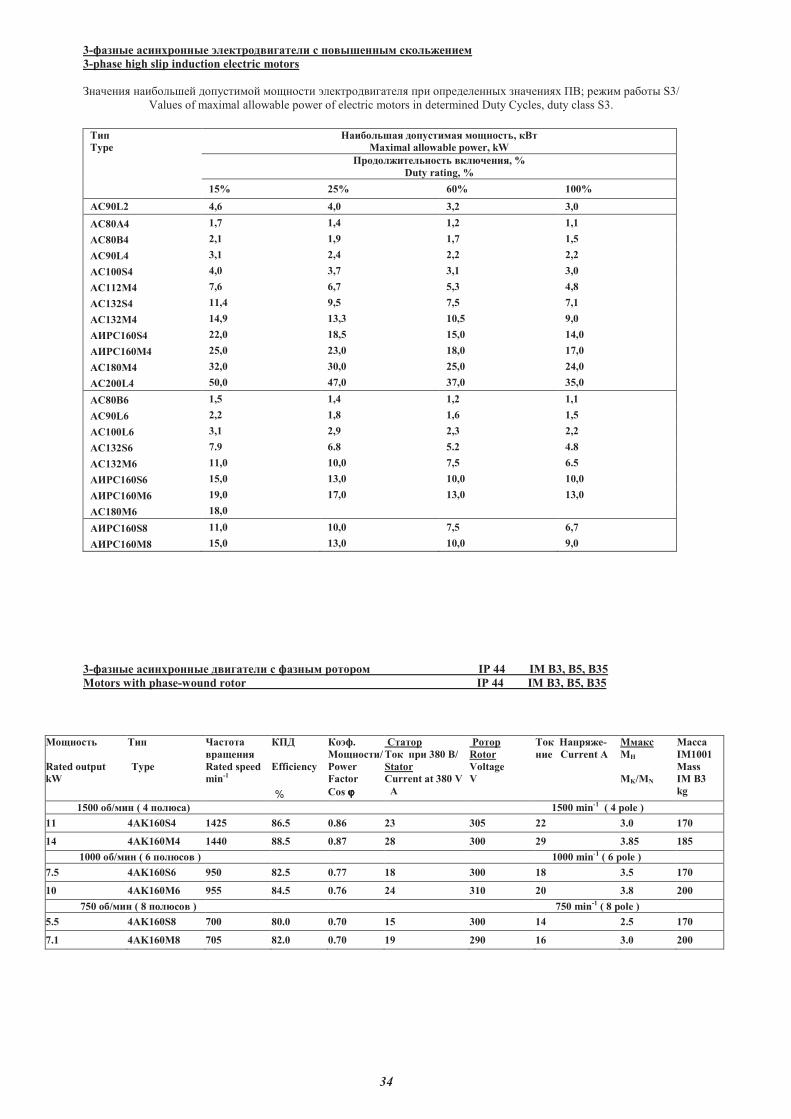
34
3-������ ��������� � ����������� � � ���������� ��� �������
3-phase high slip induction electric motors
�������� ������� ������� ������ ������������� ��� ���������� ��������� ��; ����� ����� S3/
Values of maximal allowable power of electric motors in determined Duty Cycles, duty class S3.
���
Type
����� ���� ���������� ��������, ���
Maximal allowable power, kW
���� ���� ������ �� !����, %
Duty rating, %
15% 25% 60% 100%
AC90L2 4,6 4,0 3,2 3,0
AC80"4 1,7 1,4 1,2 1,1
"#80�4 2,1 1,9 1,7 1,5
"#90L4 3,1 2,4 2,2 2,2
AC100S4 4,0 3,7 3,1 3,0
AC112M4 7,6 6,7 5,3 4,8
AC132S4 11,4 9,5 7,5 7,1
AC132M4 14,9 13,3 10,5 9,0
A$%C160S4 22,0 18,5 15,0 14,0
A$%C160M4 25,0 23,0 18,0 17,0
"#180&4 32,0 30,0 25,0 24,0
"#200L4 50,0 47,0 37,0 35,0
"#80�6 1,5 1,4 1,2 1,1
"#90L6 2,2 1,8 1,6 1,5
AC100L6 3,1 2,9 2,3 2,2
"#132S6 7.9 6.8 5.2 4.8
"#132M6 11,0 10,0 7,5 6.5
"$%C160S6 15,0 13,0 10,0 10,0
"$%C160M6 19,0 17,0 13,0 13,0
"#180&6 18,0
"$%C160S8 11,0 10,0 7,5 6,7
"$%C160M8 15,0 13,0 10,0 9,0
3-������ ��������� ������� � � ������ ����� IP 44 IM �3, B5, �35
Motors with phase-wound rotor IP 44 IM �3, B5, �35
&�������
Rated output
kW
���
Type
'������
�������
Rated speed
min-1
(�)
Efficiency
%
(���.
&�������/
Power
Factor
Cos ϕϕϕϕ
#����
��� �� 380 �/
Stator
Current at 380 V
A
%���
Rotor
Voltage
V
��� ������-
��� #urrent A
M����
M�
MK/MN
&����
IM1001
Mass
IM B3
kg
1500 ��/��� ( 4 �� ��) 1500 min-1 ( 4 pole )
11 4AK160S4 1425 86.5 0.86 23 305 22 3.0 170
14 4AK160M4 1440 88.5 0.87 28 300 29 3.85 185
1000 ��/��� ( 6 �� ��� ) 1000 min-1 ( 6 pole )
7.5 4AK160S6 950 82.5 0.77 18 300 18 3.5 170
10 4AK160M6 955 84.5 0.76 24 310 20 3.8 200
750 ��/��� ( 8 �� ��� ) 750 min-1 ( 8 pole )
5.5 4AK160S8 700 80.0 0.70 15 300 14 2.5 170
7.1 4AK160M8 705 82.0 0.70 19 290 16 3.0 200
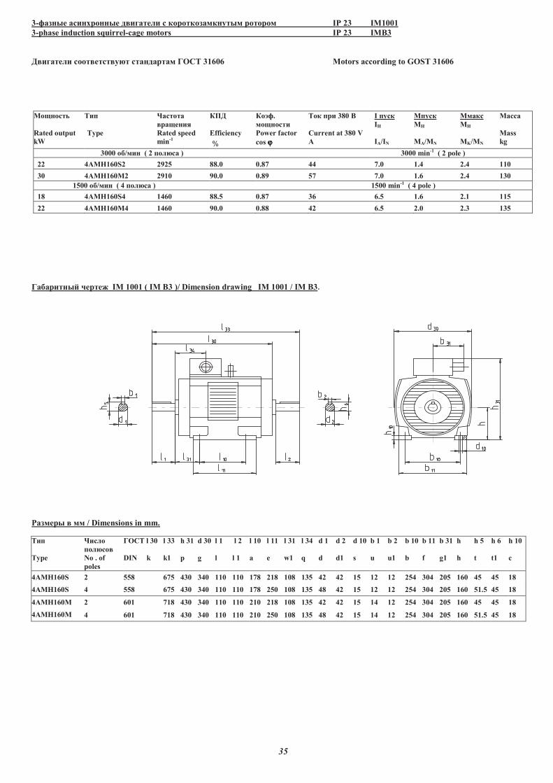
35
3-������ ��������� � ������� � ��������������� ����� IP 23 IM1001
3-phase induction squirrel-cage motors IP 23 IMB3
� ������� ���� ���� ��� ��������� ���� 31606 Motors according to GOST 31606
��������
Rated output
kW
���
Type
�������
������
Rated speed
min-1
!�
Efficiency
%
�"�.
��������
Power factor
cos ϕϕϕϕ
��� �� 380 #
Current at 380 V
A
I ����
I$
IA/IN
M����
M$
MA/MN
M����
M$
MK/MN
�����
Mass
kg
3000 �%/��� ( 2 ������ ) 3000 min-1 ( 2 pole )
22 4AMH160S2 2925 88.0 0.87 44 7.0 1.4 2.4 110
30 4AMH160M2 2910 90.0 0.89 57 7.0 1.6 2.4 130
1500 �%/��� ( 4 ������ ) 1500 min-1 ( 4 pole )
18 4AMH160S4 1460 88.5 0.87 36 6.5 1.6 2.1 115
22 4AMH160M4 1460 90.0 0.88 42 6.5 2.0 2.3 135
��%�����& '���( IM 1001 ( IM B3 )/ Dimension drawing IM 1001 / IM B3.
)����� �� / Dimensions in mm.
���
Type
�����
������
No . of
poles
���� l 30
DIN k
l 33
k1
h 31
p
d 30
g
l 1
l
l 2
l 1
l 10
a
l 11
e
l 31
w1
l 34
q
d 1
d
d 2
d1
d 10
s
b 1
u
b 2
u1
b 10
b
b 11
f
b 31
g1
h
h
h 5
t
h 6
t1
h 10
c
4*�$160S
4*�$160S
2 558 675 430 340 110 110 178 218 108 135 42 42 15 12 12 254 304 205 160 45 45 18
4 558 675 430 340 110 110 178 250 108 135 48 42 15 12 12 254 304 205 160 51.5 45 18
4*�$160M
4*�$160M
2 601 718 430 340 110 110 210 218 108 135 42 42 15 14 12 254 304 205 160 45 45 18
4 601 718 430 340 110 110 210 250 108 135 48 42 15 14 12 254 304 205 160 51.5 45 18
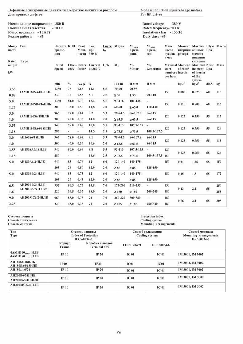
36
3-������ ��������� � ������� � ��������������� ����� 3-phase induction squirrel-cage motors
��� �� ��� ����� For lift drives______________________
����������� ��������� - 380 � Rated voltage - 380 V
����������� ������� - 50 �� Rated frequency- 50 Hz
����� �������� - 155(F) Insulation class - 155(F)
����� � ��� - S5 Duty class �S5
!�"-
�����
Rated
output
kW
#��
Type
$������
�"�-
���
Rated
Speed
min-1
�%�
Effici-
ency
%
��&�.
!�"-
�����
Power
factor
cos ϕϕϕϕ
#��
��
380 �
Current
at 380 V
A
I ����
I�
IA/IN
M����
MA
H x m
M ���� ��.
� ��.
MK
Motor
H x m
M ���� ��.
���.
MK
Generator
H x m
!���.
�����
�����
���
Maximal
start
numbers
per hour
!�����
������
����
Moment
of rotor
inertia
kg�2
!�����
�����'
������
������
�������
Maximal
moment
of inertia
of the
system
kg�2
(��
Lpa
Noise
Lpa
dBA
!����
Mass
kg
3.55 4AMH160SA4/16�)*
1380 75 0.65 11.1 5.5 70-90 70-95 - 150 0.088 0.625 60 115
0.88 330 30 0.55 8.1 2.5 ≥≥≥≥ 50 ≥≥≥≥ 55 90-110
5.0 4AMH160SB4/16�)*
1380 81.0 0.70 13,4 5.5 97-116 101-136 - 150 0.110 0.800 60 115
1.25 300 32.0 0.50 11,8 2.0 60-70 ≥≥≥≥ 65.0 110-130
3.0 4AMH160S6/18�)*
965 77.0 0.64 9.2 5.3 78-94.5 86-107.8 86-115 120 0.125 0.750 55 115
1.0 300 40.0 0,36 14.0 2.0 ≥≥≥≥ 63.5 ≥≥≥≥ 63.5 86-115
3.55 4AMH180SA6/18�)*
940 78.0 0.69 10,0 5,5 93-113 107.5-135 - 120 0.125 0.750 55 124
1.18 283 - - 14.5 2.5 ≥≥≥≥ 73.5 ≥≥≥≥ 73.5 109.5-137.5
3.0 +�160S6/18�)* 965 78.0 0.64 9.1 5.3 78-94.5 86-107.8 86-115 120 0.125 0.750 55 115
1.0 300 40.0 0,36 10.6 2.0 ≥≥≥≥ 63.5 ≥≥≥≥ 63.5 86-115
3.55 +�180S+6/18�)* 940 80.0 0.69 9.8 5,5 93-113 107.5-135 - 120 0.125 0.750 55 124
1.18 280 - - 14.6 2.5 ≥≥≥≥ 73.5 ≥≥≥≥ 73.5 109.5-137.5 150
5.0 +�180+6/24�)* 940 83 0.76 12 6.0 120-140 140-175 150 0.21 1.26 55 159
205 26 0.50 12.9 2.0 ≥≥≥≥ 85 ≥≥≥≥ 85 125-150
5.0 +�180�6/24�)* 940 85 0.75 12 6.0 120-140 140-175 180 0.25 1.3 55 172
205 29 0.45 12.9 2.0 ≥≥≥≥ 85 ≥≥≥≥ 85 125-150
6.5 +�200�6/24�)*
+�200�6/24�)*,
955 86,5 0,77 14,8 7,0 175-200 210-255 - 150 0,43 2,1 55
250
1.6 220 36,5 0,37 18,0 2,0 ≥≥≥≥ 150 ≥≥≥≥ 150 200-245 180 255
9.0 +�200!-6/24�)* 960 88,0 0,73 21 7,0 260-320 300-380 - 180 0,76 2,1 55 305
2.25 220 43,0 0,35 22 2,0 ≥≥≥≥ 185 ≥≥≥≥ 185 260-340 180
-������ ��"��� Protection index
-���� ��������� Cooling system
-���� ������� Mounting arrangements
#��
Type
-������ ��"���
Index of Protection
IEC 60034-5
-���� ���������
Cooling system
-���� �������
Mounting arrangements
IEC 60034-7
�����
Frame
K�� �� � ���
Terminal box �.-# 20459 IEC 60034-6
4AMH160���)*
4AMH180���)*IP 10 IP 20 IC 01 IC 01 IM 3001, IM 3002
+�160S6/18�)*
+�180S+6/18�)*IP10 IP20 IC01 IC01 IM 3002, IM 3009
+�180�.6/24 IP 10 IP 20 IC 01 IC 01 IM 3001, IM 3002
+�200�6/24�)*
+�200�6/24�)*,IP 10 IP 20 IC 01 IC 01 IM 3001; IM 3002
+�200!-6/24�)* IP 10 IP 20 IC 01 IC 01 IM 3001; IM 3002
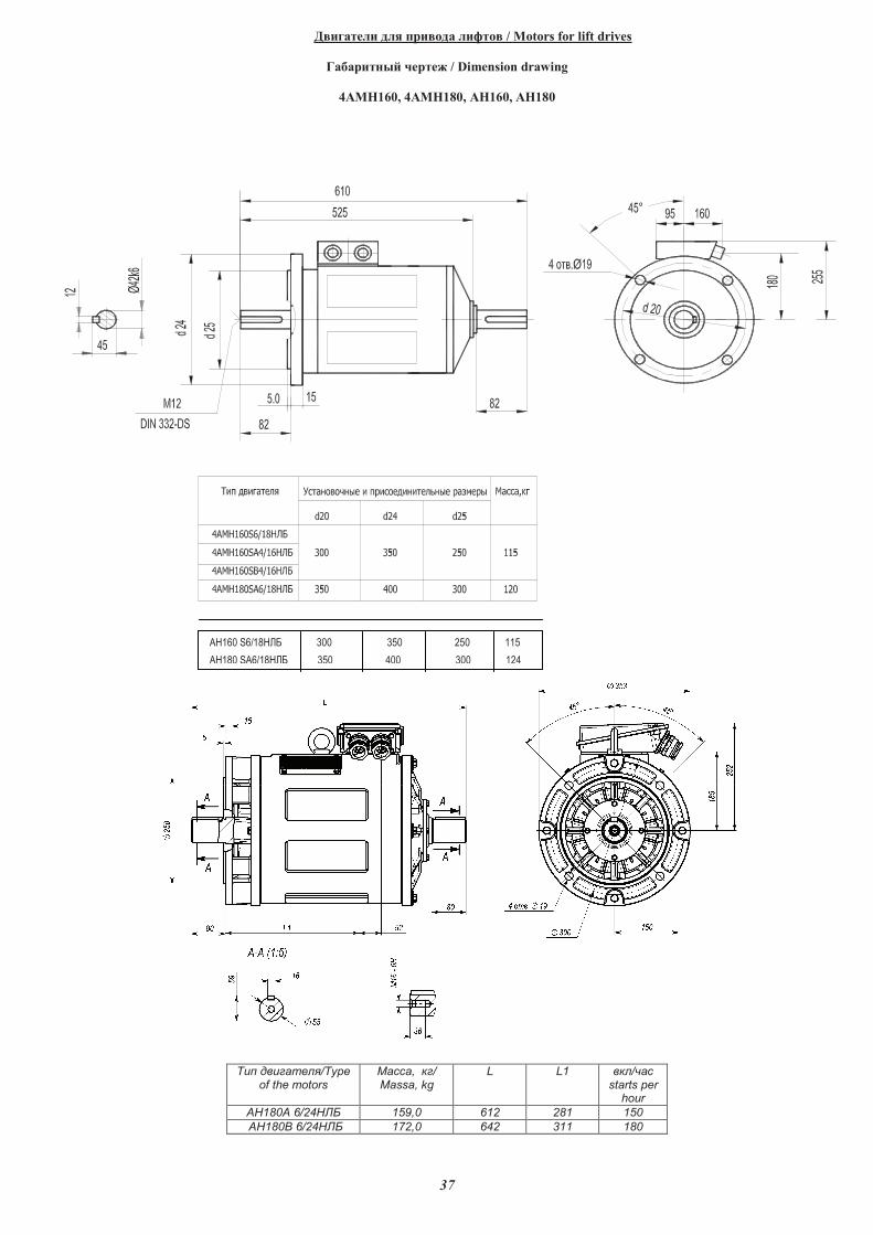
37
��������� � ���� � ���� � / Motors for lift drives
���������� ������ / Dimension drawing
4���160, 4���180, ��160, ��180
��180_6/24
��� �������/Type of the motors
�� �, ��/ Massa, kg
L L1 ��/�� starts per
hour
��180� 6/24��� 159,0 612 281 150
��180� 6/24��� 172,0 642 311 180
���������������������������������������������������� ����������������������� ����������������� ��
������������������������� ����������������������������������������������������������������������������
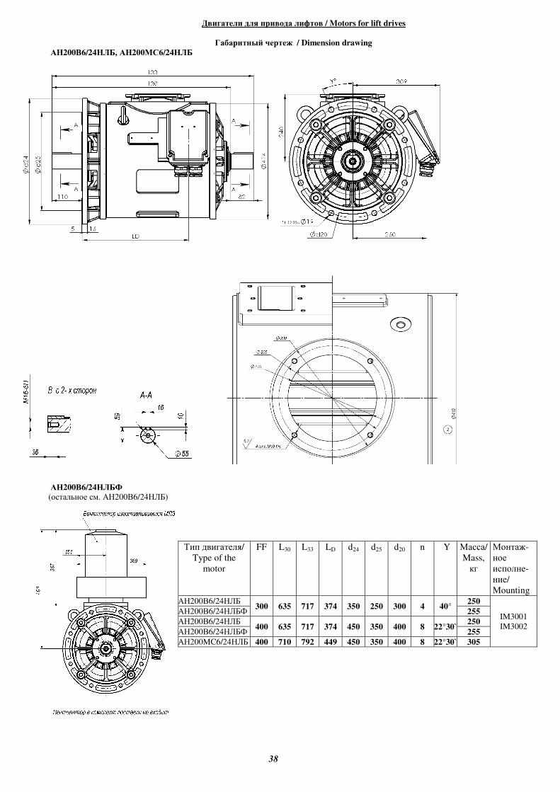
38
Двигатели для привода лифтов / Motors for lift drives
Габаритный чертеж / Dimension drawing
АН200В6/24НЛБ, АН200МС6/24НЛБ
АН200В6/24НЛБФ
(остальное см. АН200В6/24НЛБ)
Тип двигателя/
Type of the
motor
FF L30 L33 LD d24 d25 d20 n Y Масса/
Mass,
кг
Монтаж-
ное
исполне-
ние/
Mounting АН200В6/24НЛБ
300 635 717 374 350 250 300 4 40° 250
IM3001
IM3002
АН200В6/24НЛБФ 255
АН200В6/24НЛБ 400 635 717 374 450 350 400 8 22°30`
250
АН200В6/24НЛБФ 255
АН200MC6/24НЛБ 400 710 792 449 450 350 400 8 22°30` 305
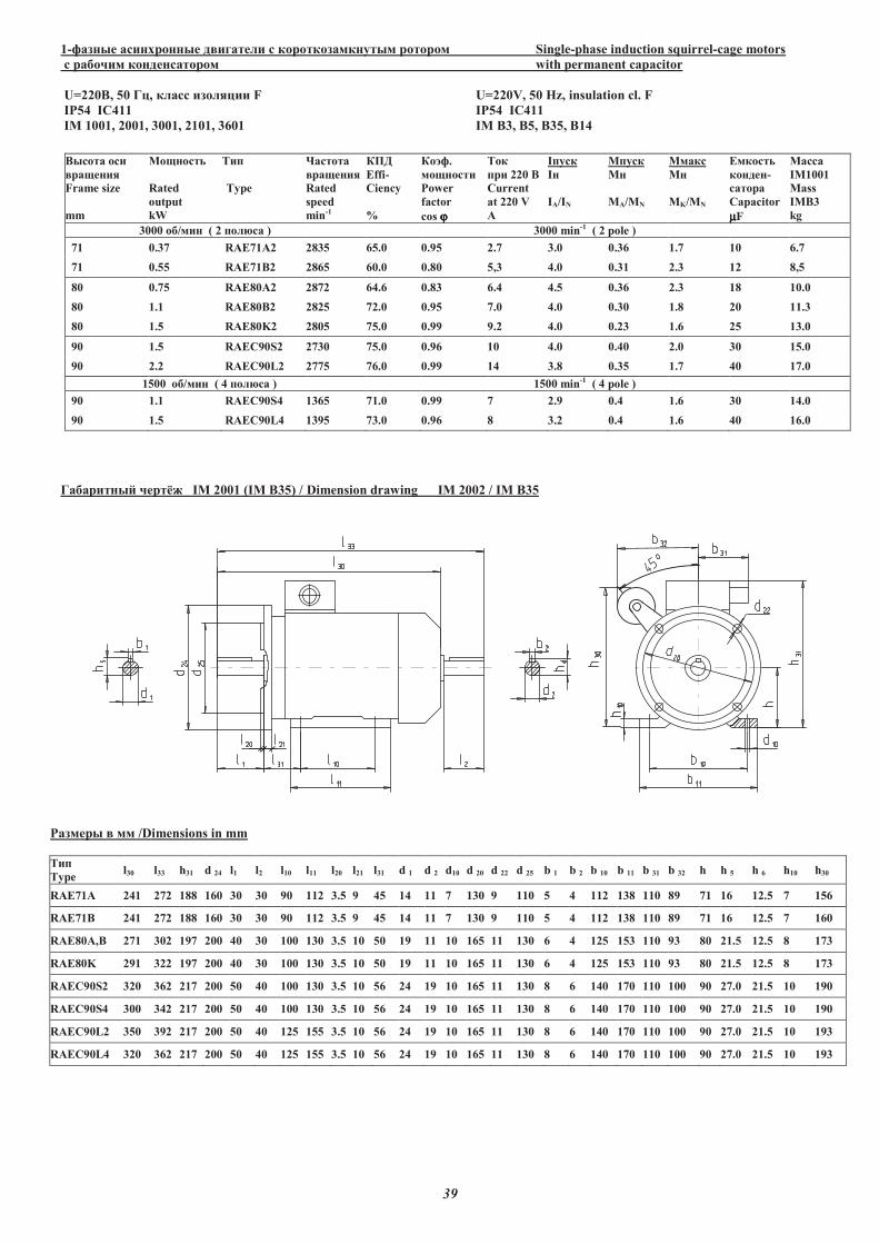
39
1-������ ��������� � ������� � ��������������� ����� Single-phase induction squirrel-cage motors
� ������ ������������ with permanent capacitor
U=220B, 50 ��, ����� �������� F U=220V, 50 Hz, insulation cl. F
IP54 IC411 IP54 IC411
IM 1001, 2001, 3001, 2101, 3601 IM B3, B5, B35, B14
������ ���
������
Frame size
mm
��������
Rated
output
kW
���
Type
�������
������
Rated
speed
min-1
!"
Effi-
Ciency
%
�#�.
��������
Power
factor
cos ϕϕϕϕ
���
�� 220 �
Current
at 220 V
A
I����
I�
IA/IN
M����
M�
MA/MN
M����
M�
MK/MN
$������
������-
�����
%apacitor
µµµµF
�����
IM1001
Mass
IMB3
kg
3000 ��/��� ( 2 ���&�� ) 3000 min-1 ( 2 pole )
71 0.37 RAE71A2 2835 65.0 0.95 2.7 3.0 0.36 1.7 10 6.7
71 0.55 RAE71B2 2865 60.0 0.80 5,3 4.0 0.31 2.3 12 8,5
80 0.75 RAE80A2 2872 64.6 0.83 6.4 4.5 0.36 2.3 18 10.0
80 1.1 RAE80B2 2825 72.0 0.95 7.0 4.0 0.30 1.8 20 11.3
80 1.5 RAE80K2 2805 75.0 0.99 9.2 4.0 0.23 1.6 25 13.0
90 1.5 RAEC90S2 2730 75.0 0.96 10 4.0 0.40 2.0 30 15.0
90 2.2 RAEC90L2 2775 76.0 0.99 14 3.8 0.35 1.7 40 17.0
1500 ��/��� ( 4 ���&�� ) 1500 min-1 ( 4 pole )
90 1.1 RAEC90S4 1365 71.0 0.99 7 2.9 0.4 1.6 30 14.0
90 1.5 RAEC90L4 1395 73.0 0.96 8 3.2 0.4 1.6 40 16.0
��������' ���() IM 2001 (IM B35) / Dimension drawing IM 2002 / IM B35
*����� �� /Dimensions in mm
���
Type l30 l33 h31 d 24 l1 l2 l10 l11 l20 l21 l31 d 1 d 2 d10 d 20 d 22 d 25 b 1 b 2 b 10 b 11 b 31 b 32 h h 5 h 6 h10 h30
RAE71A 241 272 188 160 30 30 90 112 3.5 9 45 14 11 7 130 9 110 5 4 112 138 110 89 71 16 12.5 7 156
RAE71B 241 272 188 160 30 30 90 112 3.5 9 45 14 11 7 130 9 110 5 4 112 138 110 89 71 16 12.5 7 160
RAE80A,B 271 302 197 200 40 30 100 130 3.5 10 50 19 11 10 165 11 130 6 4 125 153 110 93 80 21.5 12.5 8 173
RAE80K 291 322 197 200 40 30 100 130 3.5 10 50 19 11 10 165 11 130 6 4 125 153 110 93 80 21.5 12.5 8 173
RAEC90S2 320 362 217 200 50 40 100 130 3.5 10 56 24 19 10 165 11 130 8 6 140 170 110 100 90 27.0 21.5 10 190
RAEC90S4 300 342 217 200 50 40 100 130 3.5 10 56 24 19 10 165 11 130 8 6 140 170 110 100 90 27.0 21.5 10 190
RAEC90L2 350 392 217 200 50 40 125 155 3.5 10 56 24 19 10 165 11 130 8 6 140 170 110 100 90 27.0 21.5 10 193
RAEC90L4 320 362 217 200 50 40 125 155 3.5 10 56 24 19 10 165 11 130 8 6 140 170 110 100 90 27.0 21.5 10 193
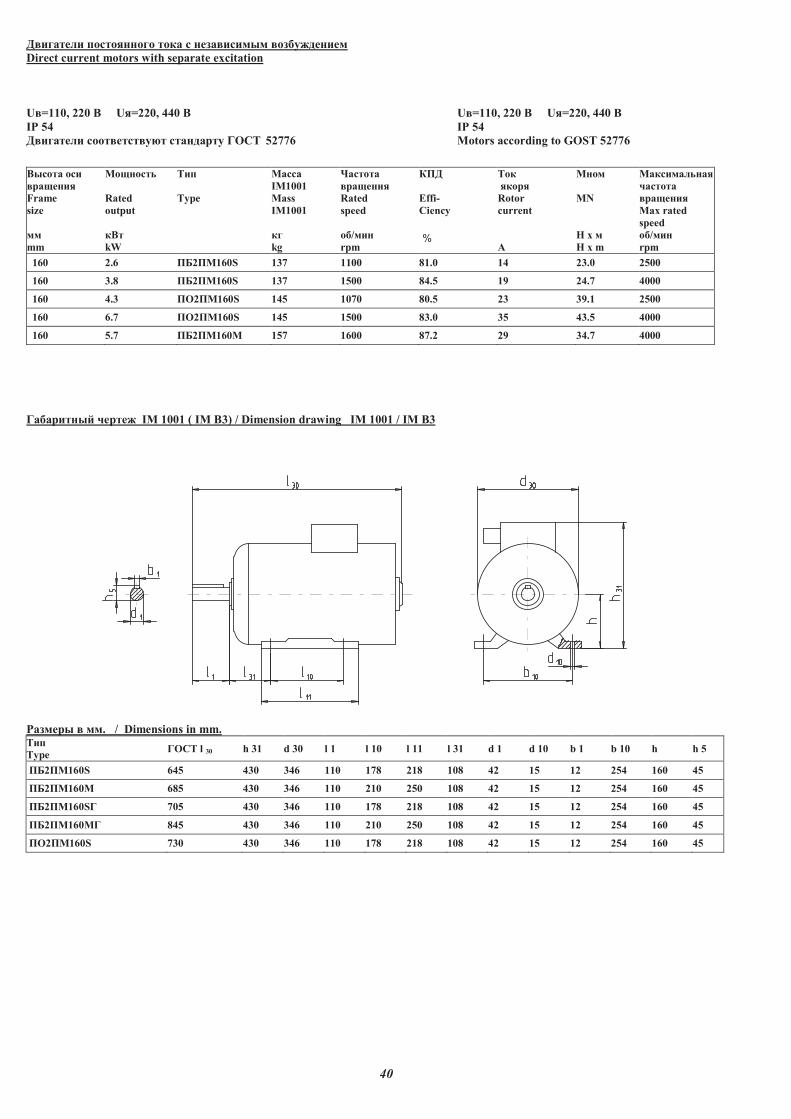
40
��������� ��� � ��� c ���������� ������� ���
Direct current motors with separate excitation
U�=110, 220 � U�=220, 440 � U�=110, 220 � U�=220, 440 �
IP 54 IP 54
��������� ����������� ��� ����� ���� 52776 Motors according to GOST 52776
����� ��
����� ��
Frame
size
��
mm
�� ���
Rated
output
���
kW
��
Type
�����
IM1001
Mass
IM1001
��
kg
�����
����� ��
Rated
speed
�/��
rpm
!"�
Effi-
Ciency
%
��
����
Rotor
current
#
M �
MN
H x �
H x m
��������� ��
$�����
����� ��
Max rated
speed
�/��
rpm
160 2.6 "%2"�160S 137 1100 81.0 14 23.0 2500
160 3.8 "%2"�160S 137 1500 84.5 19 24.7 4000
160 4.3 "O2"�160S 145 1070 80.5 23 39.1 2500
160 6.7 "O2"�160S 145 1500 83.0 35 43.5 4000
160 5.7 "%2"�160M 157 1600 87.2 29 34.7 4000
������� �& $����� IM 1001 ( IM B3) / Dimension drawing IM 1001 / IM B3
'������ � ��. / Dimensions in mm. ��
Type ���� l 30 h 31 d 30 l 1 l 10 l 11 l 31 d 1 d 10 b 1 b 10 h h 5
"%2"�160S 645 430 346 110 178 218 108 42 15 12 254 160 45
"%2"�160M 685 430 346 110 210 250 108 42 15 12 254 160 45
"%2"�160S� 705 430 346 110 178 218 108 42 15 12 254 160 45
"%2"�160M� 845 430 346 110 210 250 108 42 15 12 254 160 45
"�2"�160S 730 430 346 110 178 218 108 42 15 12 254 160 45
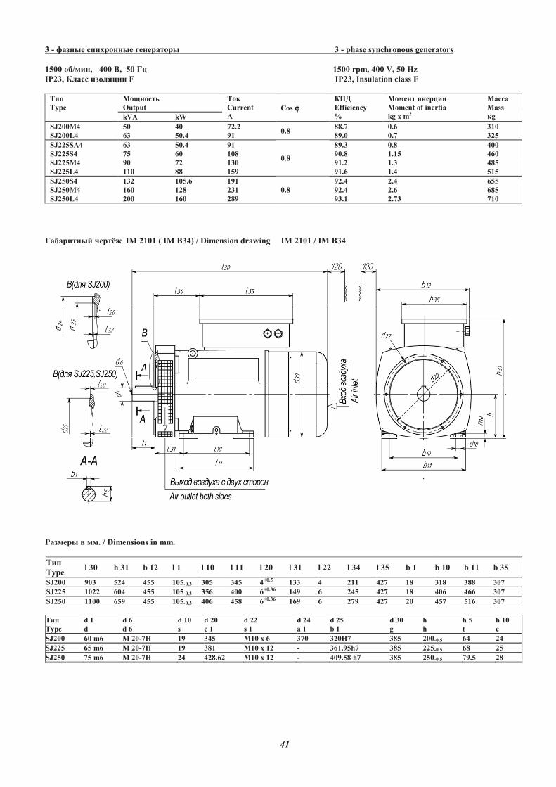
41
3 - ������ �������� ����� �� 3 - phase synchronous generators
1500 ��/���, 400 �, 50 �� 1500 rpm, 400 V, 50 Hz
IP23, ����� �������� F IP23, Insulation class F
���
Type
������ �
Output
���
Current
A
Cos ϕϕϕϕ
���
Efficiency
%
����� ������
Moment of inertia
kg x m2
�����
Mass
�g kVA kW
SJ200M4 50 40 72.2 0.8
88.7 0.6 310
SJ200L4 63 50.4 91 89.0 0.7 325
SJ225S�4 63 50.4 91
0.8
89.3 0.8 400
SJ225S4 75 60 108 90.8 1.15 460
SJ225M4 90 72 130 91.2 1.3 485
SJ225L4 110 88 159 91.6 1.4 515
SJ250S4 132 105.6 191
0.8
92.4 2.4 655
SJ250M4 160 128 231 92.4 2.6 685
SJ250L4 200 160 289 93.1 2.73 710
����� ��� � !" IM 2101 ( IM B34) / Dimension drawing IM 2101 / IM B34
#����� $ ��. / Dimensions in mm.
���
Type l 30 h 31 b 12 l 1 l 10 l 11 l 20 l 31 l 22 l 34 l 35 b 1 b 10 b 11 b 35
SJ200 903 524 455 105-0.3 305 345 4+0.5 133 4 211 427 18 318 388 307
SJ225 1022 604 455 105-0.3 356 400 6+0.36 149 6 245 427 18 406 466 307
SJ250 1100 659 455 105-0.3 406 458 6+0.36 169 6 279 427 20 457 516 307
���
Type
d 1
d
d 6
d 6
d 10
s
d 20
e 1
d 22
s 1
d 24
a 1
d 25
b 1
d 30
g
h
h
h 5
t
h 10
c
SJ200 60 m6 M 20-7H 19 345 M10 x 6 370 320H7 385 200-0.5 64 24
SJ225 65 m6 M 20-7H 19 381 M10 x 12 - 361.95h7 385 225-0.5 68 25
SJ250 75 m6 M 20-7H 24 428.62 M10 x 12 - 409.58 h7 385 250-0.5 79.5 28
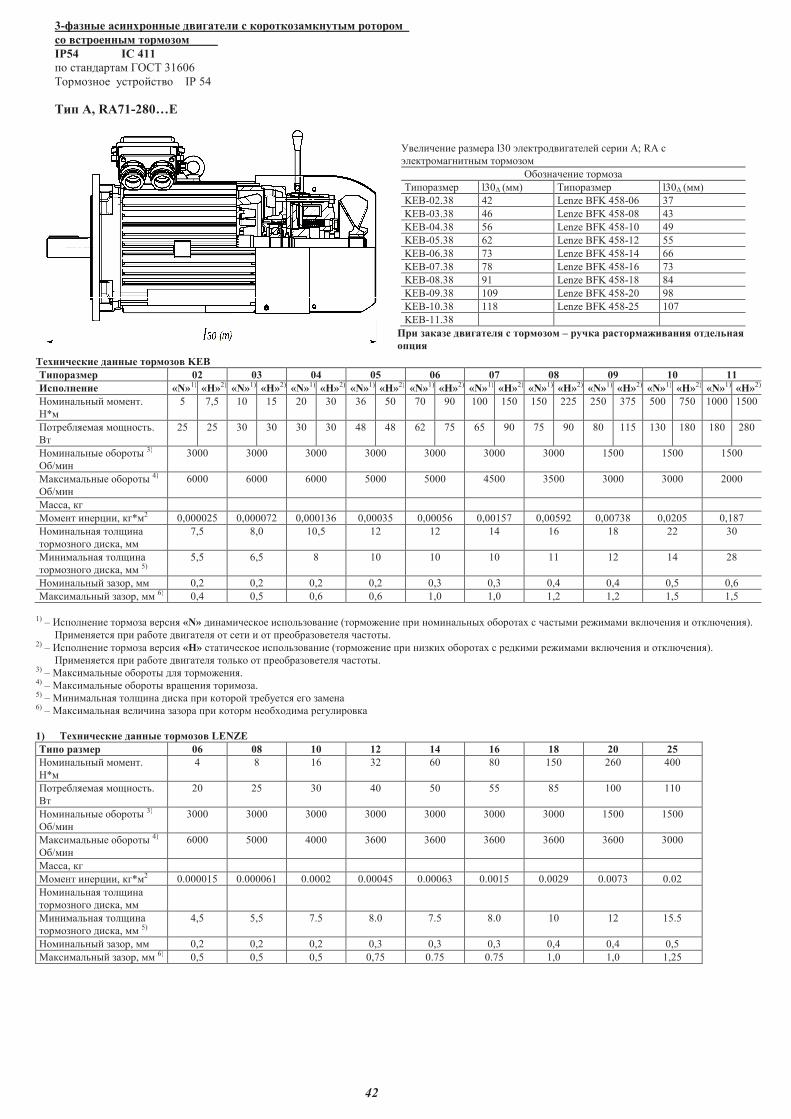
42
3-������ ��������� � ������� � ��������������� �����
c� �������� �������
IP54 IC 411
�� ��������� �� 31606
������� ���������� IP 54
��� �, RA71-280��
���������� ������ l30 ����������������� ����� �; RA �
�������������� ������
����������� ������
�������� l30� () �������� l30� ()
KEB-02.38 42 Lenze BFK 458-06 37
KEB-03.38 46 Lenze BFK 458-08 43
KEB-04.38 56 Lenze BFK 458-10 49
KEB-05.38 62 Lenze BFK 458-12 55
KEB-06.38 73 Lenze BFK 458-14 66
KEB-07.38 78 Lenze BFK 458-16 73
KEB-08.38 91 Lenze BFK 458-18 84
KEB-09.38 109 Lenze BFK 458-20 98
KEB-10.38 118 Lenze BFK 458-25 107
KEB-11.38
�� ������ � ������� � ������� � ���� �������� ���� ���������
�����
���������� ������ ������ KEB
�������� 02 03 04 05 06 07 08 09 10 11
���������� «N»1) «�»2) «N»1) «�»2) «N»1) «�»2) «N»1) «�»2) «N»1) «�»2) «N»1) «�»2) «N»1) «�»2) «N»1) «�»2) «N»1) «�»2) «N»1) «�»2)
���������� ����.
�*
5 7,5 10 15 20 30 36 50 70 90 100 150 150 225 250 375 500 750 1000 1500
������!��! �"�����.
#�
25 25 30 30 30 30 48 48 62 75 65 90 75 90 80 115 130 180 180 280
���������� ������� 3)
��/��
3000 3000 3000 3000 3000 3000 3000 1500 1500 1500
$���������� ������� 4)
��/��
6000 6000 6000 5000 5000 4500 3500 3000 3000 2000
$����, ��
$���� ����%��, ��*2 0,000025 0,000072 0,000136 0,00035 0,00056 0,00157 0,00592 0,00738 0,0205 0,187
���������! ���"���
��������� �����,
7,5 8,0 10,5 12 12 14 16 18 22 30
$��������! ���"���
��������� �����, 5)5,5 6,5 8 10 10 10 11 12 14 28
���������� �����, 0,2 0,2 0,2 0,2 0,3 0,3 0,4 0,4 0,5 0,6
$���������� �����, 6) 0,4 0,5 0,6 0,6 1,0 1,0 1,2 1,2 1,5 1,5
1) � &��������� ������ �����! «N» ����������� ������������� (����'���� ��� ���������( �������( � ������ ��'��� ���)����! � ����)����!).
����!���! ��� ������ ��������! �� ���� � �� ��������������! �������.2) � &��������� ������ �����! «�» ����������� ������������� (����'���� ��� �����( �������( � ������ ��'��� ���)����! � ����)����!).
����!���! ��� ������ ��������! ������ �� ��������������! �������. 3) � $���������� ������� ��! ����'���!. 4) � $���������� ������� ���"���! �������. 5) � $��������! ���"��� ����� ��� ������� ��������! ��� �����6) � $���������! �������� ������ ��� ����� ����(���� �����������
1) ���������� ������ ������ LENZE
���� ���� 06 08 10 12 14 16 18 20 25
���������� ����.
�*
4 8 16 32 60 80 150 260 400
������!��! �"�����.
#�
20 25 30 40 50 55 85 100 110
���������� ������� 3)
��/��
3000 3000 3000 3000 3000 3000 3000 1500 1500
$���������� ������� 4)
��/��
6000 5000 4000 3600 3600 3600 3600 3600 3000
$����, ��
$���� ����%��, ��*2 0.000015 0.000061 0.0002 0.00045 0.00063 0.0015 0.0029 0.0073 0.02
���������! ���"���
��������� �����,
$��������! ���"���
��������� �����, 5)4,5 5,5 7.5 8.0 7.5 8.0 10 12 15.5
���������� �����, 0,2 0,2 0,2 0,3 0,3 0,3 0,4 0,4 0,5
$���������� �����, 6) 0,5 0,5 0,5 0,75 0.75 0.75 1,0 1,0 1,25
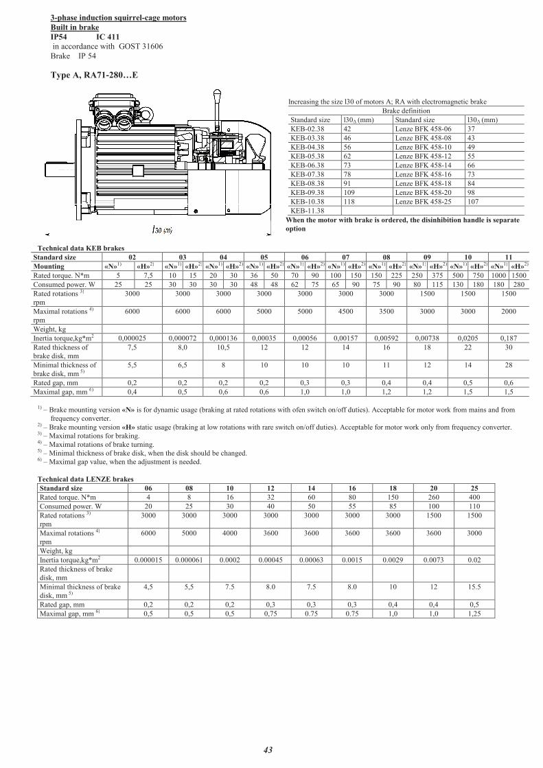
43
3-phase induction squirrel-cage motors
Built in brake
IP54 IC 411
in accordance with GOST 31606
Brake IP 54
Type �, RA71-280�$
Increasing the size l30 of motors �; RA with electromagnetic brake
Brake definition
Standard size l30� (mm) Standard size l30� (mm)
KEB-02.38 42 Lenze BFK 458-06 37
KEB-03.38 46 Lenze BFK 458-08 43
KEB-04.38 56 Lenze BFK 458-10 49
KEB-05.38 62 Lenze BFK 458-12 55
KEB-06.38 73 Lenze BFK 458-14 66
KEB-07.38 78 Lenze BFK 458-16 73
KEB-08.38 91 Lenze BFK 458-18 84
KEB-09.38 109 Lenze BFK 458-20 98
KEB-10.38 118 Lenze BFK 458-25 107
KEB-11.38
When the motor with brake is ordered, the disinhibition handle is separate
option
Technical data KEB brakes
Standard size 02 03 04 05 06 07 08 09 10 11
Mounting «N»1) «�»2) «N»1) «�»2) «N»1) «�»2) «N»1) «�»2) «N»1) «�»2) «N»1) «�»2) «N»1) «�»2) «N»1) «�»2) «N»1) «�»2) «N»1) «�»2)
Rated torque. N*m 5 7,5 10 15 20 30 36 50 70 90 100 150 150 225 250 375 500 750 1000 1500
Consumed power. W 25 25 30 30 30 30 48 48 62 75 65 90 75 90 80 115 130 180 180 280
Rated rotations 3)
rpm
3000 3000 3000 3000 3000 3000 3000 1500 1500 1500
Maximal rotations 4)
rpm
6000 6000 6000 5000 5000 4500 3500 3000 3000 2000
Weight, kg
Inertia torque,kg*m2 0,000025 0,000072 0,000136 0,00035 0,00056 0,00157 0,00592 0,00738 0,0205 0,187
Rated thickness of
brake disk, mm
7,5 8,0 10,5 12 12 14 16 18 22 30
Minimal thickness of
brake disk, mm 5)5,5 6,5 8 10 10 10 11 12 14 28
Rated gap, mm 0,2 0,2 0,2 0,2 0,3 0,3 0,4 0,4 0,5 0,6
Maximal gap, mm 6) 0,4 0,5 0,6 0,6 1,0 1,0 1,2 1,2 1,5 1,5
1) � Brake mounting version «N» is for dynamic usage (braking at rated rotations with ofen switch on/off duties). Acceptable for motor work from mains and from
frequency converter.2) � Brake mounting version «�» static usage (braking at low rotations with rare switch on/off duties). Acceptable for motor work only from frequency converter.3) � Maximal rotations for braking. 4) � Maximal rotations of brake turning. 5) � Minimal thickness of brake disk, when the disk should be changed. 6) � Maximal gap value, when the adjustment is needed.
Technical data LENZE brakes
Standard size 06 08 10 12 14 16 18 20 25
Rated torque. N*m 4 8 16 32 60 80 150 260 400
Consumed power. W 20 25 30 40 50 55 85 100 110
Rated rotations 3)
rpm
3000 3000 3000 3000 3000 3000 3000 1500 1500
Maximal rotations 4)
rpm
6000 5000 4000 3600 3600 3600 3600 3600 3000
Weight, kg
Inertia torque,kg*m2 0.000015 0.000061 0.0002 0.00045 0.00063 0.0015 0.0029 0.0073 0.02
Rated thickness of brake
disk, mm
Minimal thickness of brake
disk, mm 5)4,5 5,5 7.5 8.0 7.5 8.0 10 12 15.5
Rated gap, mm 0,2 0,2 0,2 0,3 0,3 0,3 0,4 0,4 0,5
Maximal gap, mm 6) 0,5 0,5 0,5 0,75 0.75 0.75 1,0 1,0 1,25
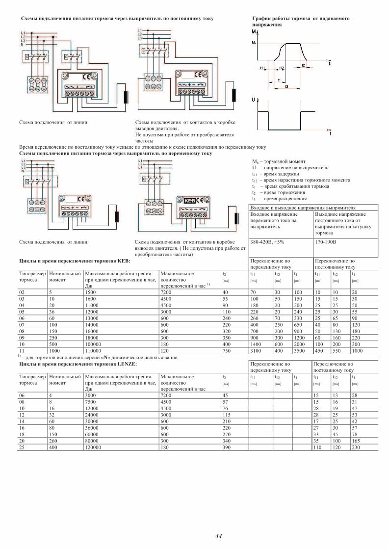
44
����� ������ �� ���� �� ������� ����� ���������� �� ������ ��� ��� ����� ������ ������� �� �����������
������ ��
� �
����� ������ �� �� � ��. ����� ������ �� �� � ����� � �����
������� ��������.
�� �������� ��� ������ �� ��������������
�������
����� ������� �� �� ������ ��� ��� �� ��� �� �� ��� �� ����� ������ �� �� ������ ��� ���
����� ������ �� ���� �� ������� ����� ���������� �� ������ ��� ���
� � � ������ �� ���� �
U � ������ �� � ����������.
t11 � ����� �������
t12 � ����� ������ �� ������ ��� ���� ��
t1 � ����� ��������� �� �������
t2 � ����� ������� ��
t3 � ����� ��� ��� ��
���� �� � ����� �� ������ �� ����������
���� �� ������ ��
������ ��� ��� �
����������
����� �� ������ ��
������ ��� ��� ��
���������� � �����
�������
����� ������ �� �� � ��. ����� ������ �� �� � ����� � �����
������� ��������. ( �� ��������� ��� ������ ��
�������������� �������)
380-420�, ±5% 170-190�
��� � ����� ������� �� �������� KEB: !������ �� ��
������ ��� ���
!������ �� ��
������ ��� ���
"���������
�������
���� �� ��
���� �
������� �� ������ ��� ��
��� �� �� ������� �� � ���,
#�
������� ��
��������
������� �� � ��� 1)
t2
[ms]
t11
[ms]
t12
[ms]
t1
[ms]
t11
[ms]
t12
[ms]
t1
[ms]
02 5 1500 7200 40 70 30 100 10 10 20
03 10 1600 4500 55 100 50 150 15 15 30
04 20 11000 4500 90 180 20 200 25 25 50
05 36 12000 3000 110 220 20 240 25 30 55
06 60 13000 600 240 260 70 330 25 65 90
07 100 14000 600 220 400 250 650 40 80 120
08 150 16000 600 320 700 200 900 50 130 180
09 250 18000 300 350 900 300 1200 60 160 220
10 500 100000 180 400 1400 600 2000 100 200 300
11 1000 110000 120 750 3100 400 3500 450 550 1000 1) � �� �������� ���� � �� ������ «N» �� �������� ��������� ��.
��� � ����� ������� �� �������� LENZE: !������ �� ��
������ ��� ���
!������ �� ��
������ ��� ���
"���������
�������
���� �� ��
���� �
������� �� ������ ��� ��
��� �� �� ������� �� � ���,
#�
������� ��
��������
������� �� � ���
t2
[ms]
t11
[ms]
t12
[ms]
t1
[ms]
t11
[ms]
t12
[ms]
t1
[ms]
06 4 3000 7200 45 15 13 28
08 8 7500 4500 57 15 16 31
10 16 12000 4500 76 28 19 47
12 32 24000 3000 115 28 25 53
14 60 30000 600 210 17 25 42
16 80 36000 600 220 27 30 57
18 150 60000 600 270 33 45 78
20 260 80000 300 340 35 100 165
25 400 120000 180 390 110 120 230
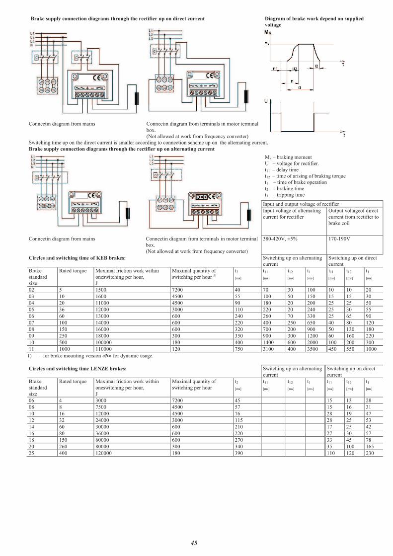
45
Brake supply connection diagrams through the rectifier up on direct current Diagram of brake work depend on supplied
voltage
� �
Connectin diagram from mains Connectin diagram from terminals in motor terminal
box.
(Not allowed at work from frequency converter)
Switching time up on the direct current is smaller according to connection scheme up on the alternating current.
Brake supply connection diagrams through the rectifier up on alternating current
� �� � braking moment
U � voltage for rectifier.
t11 � delay time
t12 � time of arising of braking torque
t1 � time of brake operation
t2 � braking time
t3 � tripping time
Input and output voltage of rectifier
Input voltage of alternating
current for rectifier
Output voltageof direct
current from rectifier to
brake coil
Connectin diagram from mains Connectin diagram from terminals in motor terminal
box.
(Not allowed at work from frequency converter)
380-420V, ±5% 170-190V
Circles and switching time of KEB brakes: Switching up on alternating
current
Switching up on direct
current
Brake
standard
size
Rated torque Maximal friction work within
oneswitching per hour,
J
Maximal quantity of
switching per hour 1)t2
[ms]
t11
[ms]
t12
[ms]
t1
[ms]
t11
[ms]
t12
[ms]
t1
[ms]
02 5 1500 7200 40 70 30 100 10 10 20
03 10 1600 4500 55 100 50 150 15 15 30
04 20 11000 4500 90 180 20 200 25 25 50
05 36 12000 3000 110 220 20 240 25 30 55
06 60 13000 600 240 260 70 330 25 65 90
07 100 14000 600 220 400 250 650 40 80 120
08 150 16000 600 320 700 200 900 50 130 180
09 250 18000 300 350 900 300 1200 60 160 220
10 500 100000 180 400 1400 600 2000 100 200 300
11 1000 110000 120 750 3100 400 3500 450 550 1000
1) � for brake mounting version «N» for dynamic usage.
Circles and switching time LENZE brakes: Switching up on alternating
current
Switching up on direct
current
Brake
standard
size
Rated torque Maximal friction work within
oneswitching per hour,
J
Maximal quantity of
switching per hour
t2
[ms]
t11
[ms]
t12
[ms]
t1
[ms]
t11
[ms]
t12
[ms]
t1
[ms]
06 4 3000 7200 45 15 13 28
08 8 7500 4500 57 15 16 31
10 16 12000 4500 76 28 19 47
12 32 24000 3000 115 28 25 53
14 60 30000 600 210 17 25 42
16 80 36000 600 220 27 30 57
18 150 60000 600 270 33 45 78
20 260 80000 300 340 35 100 165
25 400 120000 180 390 110 120 230
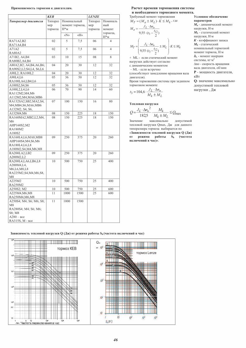
46
����������� ������ � � �������. ���� ������ ��������� ���� �
������������������������������������������������������������������������������������������������������������������������������������������������ ������������ ��������� ������.
KEB LENZE ��������� ���� ����� �
kLa� MKMMM ≤⋅±= )( , ���
)2
(55,9 123
tt
nJM oL
a
−⋅
∆⋅=
kLoL
� MKMt
t
nJM ≤⋅
����
�
�
����
�
�
±
−⋅
∆⋅=
)2
(55,9 123
+ ML - ��� ���� ���� � ����
������ ��������� �����
� � �� ���� � �����
� ML - ��� ������
(���������� ������� � ����� � ����
�� ������).
����� ����� � � ����� �� �����
����� �����
Lk
oL
MM
nJt
±
∆⋅⋅= 6,1043
����� �� ��������
max
2
5,182Q
MM
MnJQ
Lk
koL ≤±
⋅∆⋅
=
���� � ���� ���� ����� ��
������ ������ Qmax, �� ��� ���
� �������� ����� ��� ������ �
«�� ����� ���� �� �������� Q (��)
� ������ ����� Sh (����
�������� ��)».
�� ��� �����������
��������
Ma - � �� ���� � ����
������ , � �
ML - ���� ���� � ����
������ , � �
� - �!"" # �� ������
�k - ���� ���� �
� ����� �����
���� �����, � �
JL - ���� ��#
� �����, �� �2
$no - ������ ����� �
���� �� ������, �/�
� - ����� �� ������,
���
Q������ � ���� ����
����� �� ������
������ , ��
�������� � ������� � ����
���
�����
�� �����
���� �����,
�*�
� ����
���
�����
�� ���
��
����
�����,
�*�«N» «�»
RA71A2,B2
RA71A4,B4
02 5 7,5 06 4
A71A2
RA80A2
02 5 7,5 06 4
A71B2, A4,�4
RA80B2,A4,�4
03 10 15 08 8
A80A2,B2; A4,B4,A6,B6;
RA90S2,L2;S4,L4, S6,L6
04 20 30 12 32
A90L2; RA100L2 04 20 30 12 32
A90L4,L6
RA100LA4,LB4;L6
05 36 50 12 32
A100S2,S4,S6 05 36 50 12 32
A100L2,L4,L6
RA112M2,M4,M6
A112M2,M4,MA6,MB6
06 70 90 14 60
RA132SA2,SB2,MA2,S4,
M4,MB4,S6,MA6,MB6
A132M2, S4, S6,
07 100 150 16 80
A132M4,M6 08 150 225 18 150
RA160%&2,%�2,L2,%4,
M6
A'(160S2,M2
RA180M2
A180S2
08 150 225 18 150
RA160L4,L6,MA8,MB8
A'(160S4,M4,S6,M6
RA180L4,L6,L8
A180M2,S4,M4,M6,M8
09 250 375 20 260
RA200LA2,LB2
A200M2,L2
09 250 375 20 260
RA200L4,LA6,LB6,L8
A200M4,L4,
M6,L6,M8,L8
RA225M2,S4,M4,M6,S8,
M8
10 500 750 25 400
A225M2
RA250M2
10 500 750 25 400
&250S2; %2 10 500 750 25 600
A225M4,M6,M8
RA250M4,M6,M8
11 1000 1500 25 600
&250S4; %4; S6; %6; S8;
%8
RA280S4; %4; S6; %6;
S8; %8
&280 � ���
RA315S, % - ���
11 1000 1500
�
�� ����� ���� �� �������� Q (��) � ������ ����� Sh (���� �������� ��)
�
����������
� ��
���
����� �
����
��������� ��
�
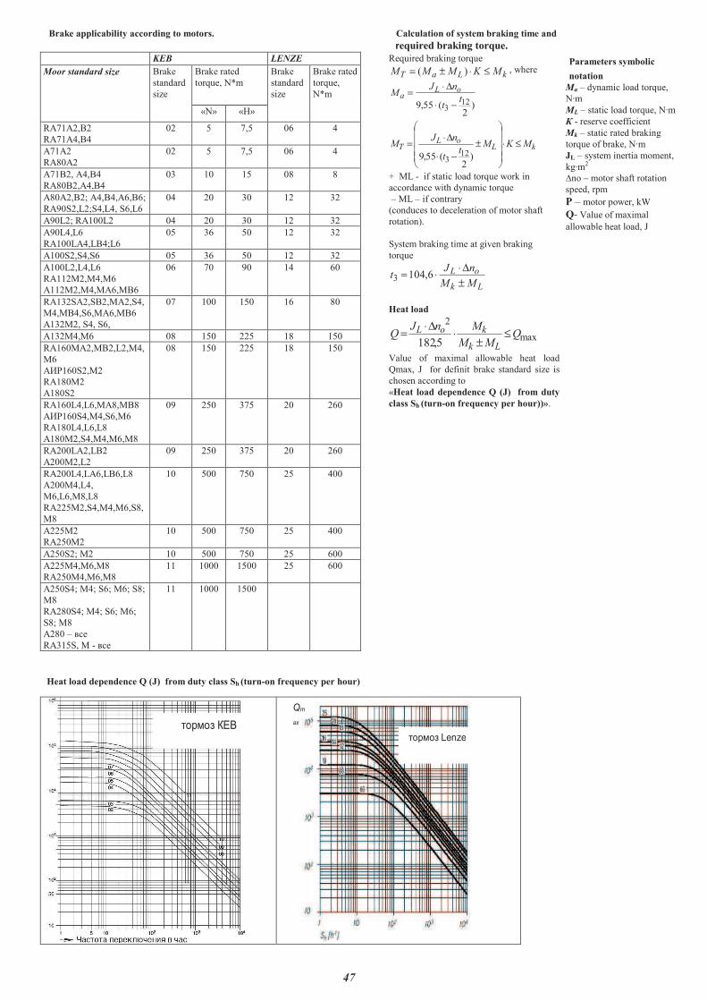
47
Brake applicability according to motors. Calculation of system braking time and �
������������������������������������������������������������������������������������������������������������������������������������������������equired braking torque.
KEB LENZE Required braking torque
kLa� MKMMM ≤⋅±= )( , where
)2
(55,9 123
tt
nJM oL
a
−⋅
∆⋅=
kLoL
� MKMt
t
nJM ≤⋅
����
�
�
����
�
�
±
−⋅
∆⋅=
)2
(55,9 123
+ ML - if static load torque work in
accordance with dynamic torque
� ML � if contrary
(conduces to deceleration of motor shaft
rotation).
System braking time at given braking
torque
Lk
oL
MM
nJt
±
∆⋅⋅= 6,1043
Heat load
max
2
5,182Q
MM
MnJQ
Lk
koL ≤±
⋅∆⋅
=
Value of maximal allowable heat load
Qmax, J for definit brake standard size is
chosen according to
«Heat load dependence Q (J) from duty
class Sh (turn-on frequency per hour))».
Parameters symbolic
notation
Ma � dynamic load torque,
N�m
ML � static load torque, N�m
� - reserve coefficient
�k � static rated braking
torque of brake, N�m
JL � system inertia moment,
kg�m2
�no � motor shaft rotation
speed, rpm
� � motor power, kW
Q��Value of maximal
allowable heat load, J
Moor standard size Brake
standard
size
Brake rated
torque, N*m
Brake
standard
size
Brake rated
torque,
N*m
«N» «�»
RA71A2,B2
RA71A4,B4
02 5 7,5 06 4
A71A2
RA80A2
02 5 7,5 06 4
A71B2, A4,�4
RA80B2,A4,�4
03 10 15 08 8
A80A2,B2; A4,B4,A6,B6;
RA90S2,L2;S4,L4, S6,L6
04 20 30 12 32
A90L2; RA100L2 04 20 30 12 32
A90L4,L6
RA100LA4,LB4;L6
05 36 50 12 32
A100S2,S4,S6 05 36 50 12 32
A100L2,L4,L6
RA112M2,M4,M6
A112M2,M4,MA6,MB6
06 70 90 14 60
RA132SA2,SB2,MA2,S4,
M4,MB4,S6,MA6,MB6
A132M2, S4, S6,
07 100 150 16 80
A132M4,M6 08 150 225 18 150
RA160��2,��2,L2,�4,
M6
A��160S2,M2
RA180M2
A180S2
08 150 225 18 150
RA160L4,L6,MA8,MB8
A��160S4,M4,S6,M6
RA180L4,L6,L8
A180M2,S4,M4,M6,M8
09 250 375 20 260
RA200LA2,LB2
A200M2,L2
09 250 375 20 260
RA200L4,LA6,LB6,L8
A200M4,L4,
M6,L6,M8,L8
RA225M2,S4,M4,M6,S8,
M8
10 500 750 25 400
A225M2
RA250M2
10 500 750 25 400
�250S2; �2 10 500 750 25 600
A225M4,M6,M8
RA250M4,M6,M8
11 1000 1500 25 600
�250S4; �4; S6; �6; S8;
�8
RA280S4; �4; S6; �6;
S8; �8
�280 � �
RA315S, � - �
11 1000 1500
�
Heat load dependence Q (J) from duty class Sh (turn-on frequency per hour)
�
����������
� ��
���
����� �
����
��������� ��
�
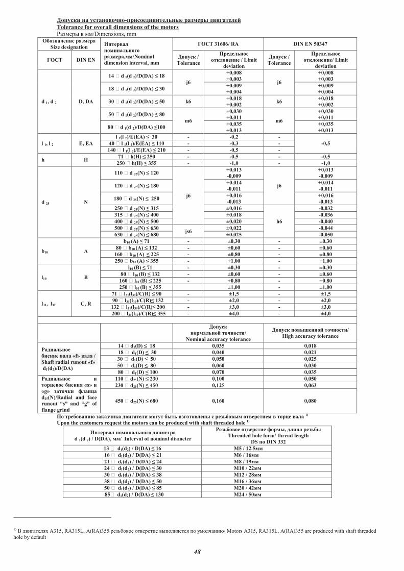
48
������� � ���������-� �������������� ��� � ��������
Tolerance for overall dimensions of the motors
������� � ��/Dimensions, mm ���������� ���
Size designation ��� ��
�����������
��� ,��/Nominal
dimension interval, mm
���� 31606/ RA DIN EN 50347
���� DIN EN ������ /
Tolerance
� ��������
��������� / Limit
deviation
������ /
Tolerance
� ��������
���������/ Limit
deviation
d 1, d 2 D, DA
14 � d 1(d 2)/D(DA) � 18
j6
+0,008
+0,003 j6
+0,008
+0,003
18 � d 1(d 2)/D(DA) � 30 +0,009
+0,004
+0,009
+0,004
30 � d 1(d 2)/D(DA) � 50 k6 +0,018
+0,002 k6
+0,018
+0,002
50 � d 1(d 2)/D(DA) � 80
m6
+0,030
+0,011 m6
+0,030
+0,011
80 � d 1(d 2)/D(DA) �100 +0,035
+0,013
+0,035
+0,013
l 1, l 2 E, EA
l 1(l 2)/E(EA) � 30 - -0,2 -
-0,5 40 � l 1(l 2)/E(EA) � 110 - -0,3 -
140 � l 1(l 2)/E(EA) � 210 - -0,5 -
h H 71 � h(H) � 250 - -0,5 - -0,5
250 � h(H) � 355 - -1,0 - -1,0
d 25 N
110 � d 25(N) � 120
j6
+0,013
-0,009
j6
+0,013
-0,009
120 � d 25(N) � 180 +0,014
-0,011
+0,014
-0,011
180 � d 25(N) � 250 +0,016
-0,013
+0,016
-0,013
250 � d 25(N) � 315 ±0,016
h6
-0,032
315 � d 25(N) � 400 ±0,018 -0,036
400 � d 25(N) � 500 ±0,020 -0,040
500 � d 25(N) � 630 js6
±0,022 -0,044
630 � d 25(N) � 680 ±0,025 -0,050
b10 A
b10 (A) � 71 - ±0,30 - ±0,30
80 � b10 (A) � 132 - ±0,60 - ±0,60
160 � b10 (A) � 225 - ±0,80 - ±0,80
250 � b10 (A) � 355 - ±1,00 - ±1,00
l10 B
l10 (B) � 71 - ±0,30 - ±0,30
80 � l10 (B) � 132 - ±0,60 - ±0,60
160 � l10 (B) � 225 - ±0,80 - ±0,80
250 � l10 (B) � 355 ±1,00 - ±1,00
l31, l39 C, R
71 � l31(l39)/C(R) � 90 - ±1,5 - ±1,5
90 � l31(l39)/C(R)� 132 - ±2,0 - ±2,0
132 � l31(l39)/C(R)� 200 - ±3,0 - ±3,0
200 � l31(l39)/C(R)� 355 - ±4,0 - ±4,0
������
�� ������ ������/
Nominal accuracy tolerance
������ ���� ����� ������/
High accuracy tolerance
!�������
������ �� «f» �� /
Shaft radial runout «f»
d1(d2)/D(DA)
14 � d1(D) � 18 0,035 0,018
18 � d1(D) � 30 0,040 0,021
30 � d1(D) � 50 0,050 0,025
50 � d1(D) � 80 0,060 0,030
80 � d1(D) � 100 0,070 0,035
!������� �
� "���� �����# «s» �
«g» ����� $��"
d25(N)/Radial and face
runout �s� and �g� of
flange grind
110 � d25(N) � 230 0,100 0,050
230 � d25(N) � 450 0,125 0,063
450 � d25(N) � 680 0,160 0,080
�� ������% ������ ������� ���� ��� ���������� � �������� ��� ���� � � "� �� 1)
Upon the customers request the motors can be produced with shaft threaded hole 1)
1) ���� ���� A315, RA315L, A(RA)355 ��������� � ���� �� �������� �� �� ���������/ Motors A315, RA315L, A(RA)355 are produced with shaft threaded hole by default
��� �� ����������� ����
d 1(d 2) / D(DA), ��/ Interval of nominal diameter
!�������� ��� ��� $� ��, ���� �����
Threaded hole form/ thread length
DS �� DIN 332
13 � d1(d2) / D(DA) � 16 &5 / 12.5��
16 � d1(d2) / D(DA) � 21 &6 / 16��
21 � d1(d2) / D(DA) � 24 &8 / 19��
24 � d1(d2) / D(DA) � 30 &10 / 22��
30 � d1(d2) / D(DA) � 38 &12 / 28��
38 � d1(d2) / D(DA) � 50 &16 / 36��
50 � d1(d2) / D(DA) � 85 &20 / 42��
85� d1(d2) / D(DA) � 130 &24 / 50��
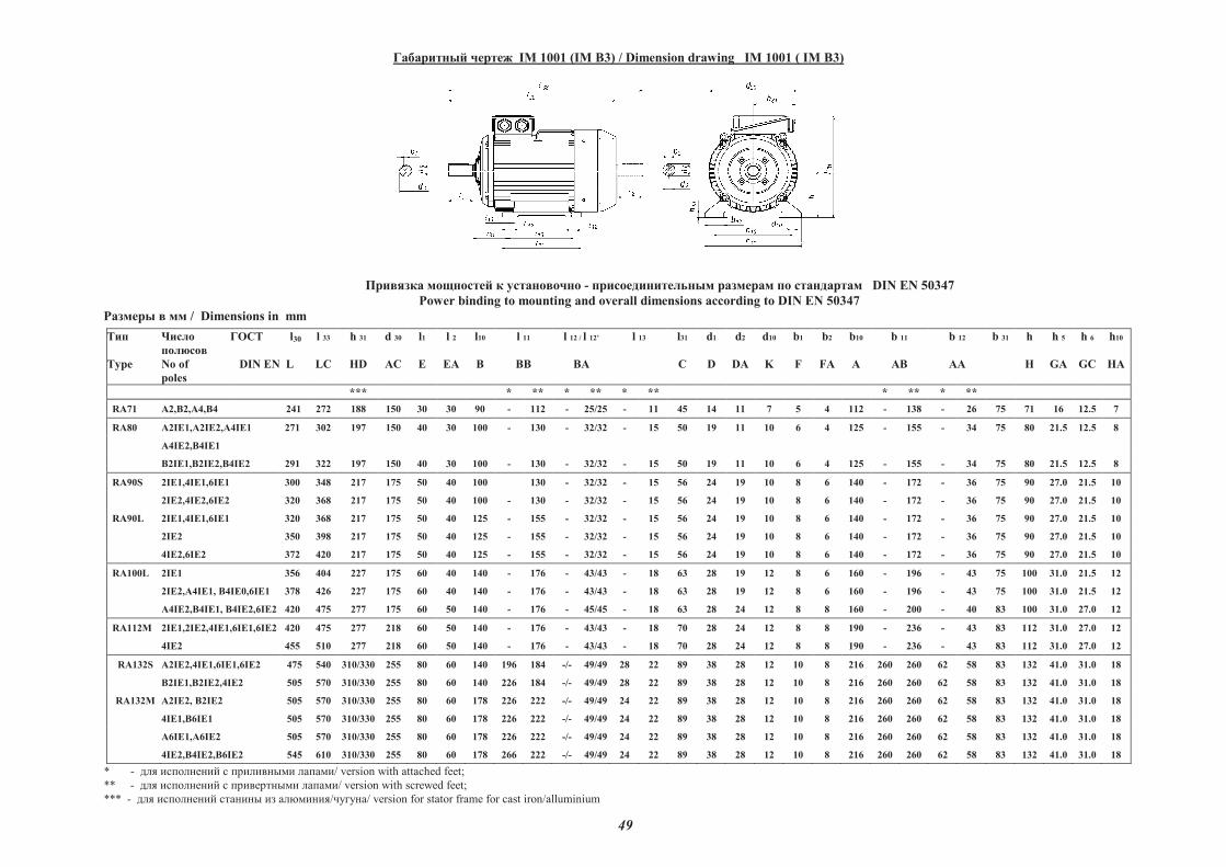
49
��������� ����� IM 1001 (IM B3) / Dimension drawing IM 1001 ( IM B3)
������� �������� � ���������� - ����������������� �������� �� ���������� DIN EN 50347
Power binding to mounting and overall dimensions according to DIN EN 50347
������� � �� / Dimensions in mm
���
Type
�����
�������
No of
poles
�� � l30
DIN EN L
l 33
LC
h 31
HD
d 30
AC
l1
E
l 2
EA
l10
B
l 11
BB
l 12 / l 12�
BA
l 13 l31
C
d1
D
d2
DA
d10
K
b1
F
b2
FA
b10
A
b 11
AB
b 12
AA
b 31 h
H
h 5
GA
h 6
GC
h10
HA
*** * ** * ** * ** * ** * **
RA71 !2,"2,!4,"4 241 272 188 150 30 30 90 - 112 - 25/25 - 11 45 14 11 7 5 4 112 - 138 - 26 75 71 16 12.5 7
RA80 !2I#1,!2I#2,!4I#1 271 302 197 150 40 30 100 - 130 - 32/32 - 15 50 19 11 10 6 4 125 - 155 - 34 75 80 21.5 12.5 8
!4I#2,"4I#1
"2I#1,"2I#2,"4I#2 291 322 197 150 40 30 100 - 130 - 32/32 - 15 50 19 11 10 6 4 125 - 155 - 34 75 80 21.5 12.5 8
RA90S 2I#1,4I#1,6I#1 300 348 217 175 50 40 100 130 - 32/32 - 15 56 24 19 10 8 6 140 - 172 - 36 75 90 27.0 21.5 10
2I#2,4I#2,6I#2 320 368 217 175 50 40 100 - 130 - 32/32 - 15 56 24 19 10 8 6 140 - 172 - 36 75 90 27.0 21.5 10
RA90L 2I#1,4I#1,6I#1 320 368 217 175 50 40 125 - 155 - 32/32 - 15 56 24 19 10 8 6 140 - 172 - 36 75 90 27.0 21.5 10
2I#2 350 398 217 175 50 40 125 - 155 - 32/32 - 15 56 24 19 10 8 6 140 - 172 - 36 75 90 27.0 21.5 10
4I#2,6I#2 372 420 217 175 50 40 125 - 155 - 32/32 - 15 56 24 19 10 8 6 140 - 172 - 36 75 90 27.0 21.5 10
RA100L 2I#1 356 404 227 175 60 40 140 - 176 - 43/43 - 18 63 28 19 12 8 6 160 - 196 - 43 75 100 31.0 21.5 12
2I#2,A4I#1, B4I#0,6I#1
A4I#2,"4I#1, "4I#2,6I#2
378
420
426
475
227
277
175
175
60
60
40
50
140
140
-
-
176
176
-
-
43/43
45/45
-
-
18
18
63
63
28
28
19
24
12
12
8
8
6
8
160
160
-
-
196
200
-
-
43
40
75
83
100
100
31.0
31.0
21.5
27.0
12
12
RA112M
2I#1,2I#2,4I#1,6I#1,6I#2
4I#2
420
455
475
510
277
277
218
218
60
60
50
50
140
140
-
-
176
176
-
-
43/43
43/43
-
-
18
18
70
70
28
28
24
24
12
12
8
8
8
8
190
190
-
-
236
236
-
-
43
43
83
83
112
112
31.0
31.0
27.0
27.0
12
12
RA132S
A2I#2,4I#1,6I#1,6I#2
"2I#1,"2I#2,4I#2
475
505
540
570
310/330
310/330
255
255
80
80
60
60
140
140
196
226
184
184
-/-
-/-
49/49
49/49
28
28
22
22
89
89
38
38
28
28
12
12
10
10
8
8
216
216
260
260
260
260
62
62
58
58
83
83
132
132
41.0
41.0
31.0
31.0
18
18
RA132M A2I#2, "2I#2
4I#1,"6I#1
505
505
570
570
310/330
310/330
255
255
80
80
60
60
178
178
226
226
222
222
-/-
-/-
49/49
49/49
24
24
22
22
89
89
38
38
28
28
12
12
10
10
8
8
216
216
260
260
260
260
62
62
58
58
83
83
132
132
41.0
41.0
31.0
31.0
18
18
!6I#1,!6I#2
4I#2,"4I#2,"6I#2
505
545
570
610
310/330
310/330
255
255
80
80
60
60
178
178
226
266
222
222
-/-
-/-
49/49
49/49
24
24
22
22
89
89
38
38
28
28
12
12
10
10
8
8
216
216
260
260
260
260
62
62
58
58
83
83
132
132
41.0
41.0
31.0
31.0
18
18
* - ��� �������� � ������� �� ������/ version with attached feet;
** - ��� �������� � ������� �� ������/ version with screwed feet;
*** - ��� �������� ������ �� ��������/������/ version for stator frame for cast iron/alluminium

50
��������� ����� IM 1001 ( IM B3) / Dimension drawing IM 1001 ( IM B3)
������� �������� � ���������� - ����������������� �������� �� ���������� DIN EN 50347
Power binding to mounting and overall dimensions in according to DIN EN 50347
������� � �� / Dimensions in mm
Type
�����
�������
� of poles
�� ! l30
DIN EN L
l 33
LC
h 31
HD
d 30
AC
l1
E
l 2
EA
l10
B
l 11
BB
l 12 / l 12�
BA
l 13 l31
C
d1
D
d2
DA
d10
K
b1
F
b2
FA
b10
A
b 11
AB
b 12
AA
b 31 h
H
h 5
GA
h 6
GC
h10
HA
* ** * ** * ** * **
RA160M "2IE1,"2IE2, #2IE1,#2IE2,
4IE1,4IE2, 6IE1, 6IE2,"8,#8
605 720 405 350 110 110 210 257 253 -/- 45/45 19 20 108 42 42 15 12 12 254 300 45 65 160 160 45.0 45.0 20
RA160L 2IE1,2IE2,4IE1,4IE2,6IE1,6IE2,8 645 760 405 350 110 110 254 297 297 -/- 45/45 19 20 108 42 42 15 12 12 254 300 45 65 160 160 45.0 45.0 20
RA180M 2IE1,2IE2,4IE1, 4IE2 645 760 425 350 110 110 241 290 290 -/- 90/90 19 23 121 48 42 15 14 12 279 330 75 80 160 180 51.5 45.0 23
RA180L 4IE1,6IE1,6IE2,8 645 760 425 350 110 110 279 - 328 - 70/70 - 23 121 48 42 15 14 12 279 330 - 80 160 180 51.5 45.0 23
RA180L 4IE2 705 820 425 350 110 110 279 - 328 - 90/90 - 23 121 48 42 15 14 12 279 330 - 80 160 180 51.5 45.0 23
RA200L "2IE2, #2IE2 720 835 475 380 110 110 305 360 375 -/- 85/85 31 35 133 55 55 19 16 16 318 390 80 95 205 200 59.0 59.0 28
RA200L 4IE1,4IE2, "6IE1,"6IE2,B6IE1,8 720 835 475 380 110 110 305 360 375 -/- 85/85 31 35 133 55 55 19 16 16 318 390 80 95 205 200 59.0 59.0 28
RA200L B6IE2 805 920 475 380 110 110 305 360 375 -/- 85/85 31 35 133 55 55 19 16 16 318 390 80 95 205 200 59.0 59.0 28
RA225M 2IE2 805 920 500 380 110 110 311 - 380 - 85/85 - 35 149 55 55 19 16 16 356 420 - 108 205 225 59.0 59.0 28
RA225S 4IE1,8 750 865 500 380 140 110 286 - 355 - 85/85 - 35 149 60 55 19 18 16 356 420 - 108 205 225 64.0 59.0 28
RA225S 4IE2 835 950 500 380 140 110 286 - 355 - 85/85 - 35 149 60 55 19 18 16 356 420 - 108 205 225 64.0 59.0 28
RA225M 4IE1,6IE1, 6$I0,8 835 950 500 380 140 110 311 - 380 - 85/85 - 35 149 60 55 19 18 16 356 420 - 108 205 225 64.0 59.0 28
RA225M 4IE2,6IE2 870 985 515 420 140 110 311 370 380 -/- 85/85 30 30 149 60 55 19 18 16 356 438 80 80 205 225 69.0 64.0 32
RA250M 2IE1,2IE2 870 985 540 420 140 110 349 - 425 - 85/85 - 36 168 60 55 24 18 16 406 482 - 107 205 250 64.0 59.0 32
RA250M 4IE1,4IE2, 6IE1,6IE2,8 870 1015 540 420 140 140 349 - 425 - 85/85 - 36 168 65 60 24 18 18 406 482 - 107 205 250 69.0 64.0 32
RA280S 2IE1,2IE2 905 1045 645 495 140 110 368 - 440 - 85/85 - 34 190 65 55 24 18 16 457 535 - 105 225 280 69.0 59.0 32
RA280S 4IE1,4IE2,6IE1,6IE2,8 905 1075 645 495 140 140 368 - 440 - 85/85 - 34 190 75 65 24 20 18 457 535 - 105 225 280 79.5 69.0 32
RA280M 2IE1,2IE2 965 1080 645 495 140 110 419 - 495 - 85/85 - 36 190 65 55 24 18 16 457 535 - 105 225 280 69.0 59.0 32
RA280M 4IE1,4IE2,6IE1,6IE2,8 965 1110 645 495 140 140 419 - 495 - 85/85 - 36 190 75 65 24 20 18 457 535 - 105 225 280 79.5 69.0 32
* - ��� �������� � ������� �� ������/ version with attached feet
** - ��� �������� � ������� �� ������/ version with screwed feet
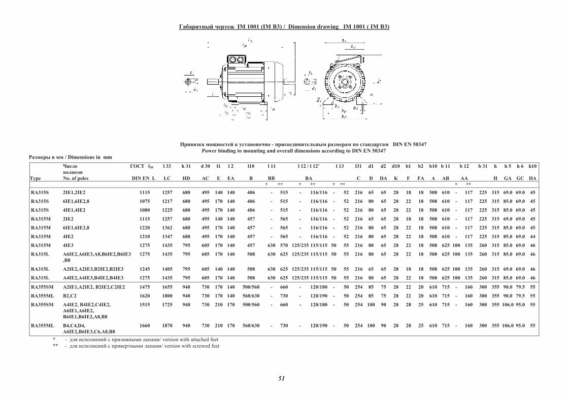
51
��������� ����� IM 1001 (IM B3) / Dimension drawing IM 1001 ( IM B3)
������� �������� � ���������� - ����������������� �������� �� ���������� DIN EN 50347
Power binding to mounting and overall dimensions according to DIN EN 50347
������� � �� / Dimensions in mm
Type
�����
�������
No. of poles
��� l30
DIN EN L
l 33
LC
h 31
HD
d 30
AC
l1
E
l 2
EA
l10
B
l 11
BB
l 12 / l 12�
BA
l 13 l31
C
d1
D
d2
DA
d10
K
b1
F
b2
FA
b10
A
b 11
AB
b 12
AA
b 31 h
H
h 5
GA
h 6
GC
h10
HA
* ** * ** * ** * **
RA315S 2IE1,2IE2 1115 1257 680 495 140 140 406 - 515 - 116/116 - 52 216 65 65 28 18 18 508 610 - 117 225 315 69.0 69.0 45
RA315S 6IE1,6IE2,8 1075 1217 680 495 170 140 406 - 515 - 116/116 - 52 216 80 65 28 22 18 508 610 - 117 225 315 85.0 69.0 45
RA315S 4IE1,4IE2 1080 1225 680 495 170 140 406 - 515 - 116/116 - 52 216 80 65 28 22 18 508 610 - 117 225 315 85.0 69.0 45
RA315M 2IE2 1115 1257 680 495 140 140 457 - 565 - 116/116 - 52 216 65 65 28 18 18 508 610 - 117 225 315 69.0 69.0 45
RA315M 6IE1,6IE2,8 1220 1362 680 495 170 140 457 - 565 - 116/116 - 52 216 80 65 28 22 18 508 610 - 117 225 315 85.0 69.0 45
RA315M 4IE2 1210 1347 680 495 170 140 457 - 565 - 116/116 - 52 216 80 65 28 22 18 508 610 - 117 225 315 85.0 69.0 44
RA315M 4IE3 1275 1435 795 605 170 140 457 630 570 125/235 115/115 50 55 216 80 65 28 22 18 508 625 100 135 260 315 85.0 69.0 46
RA315L !6IE2,!6IE3,A8,"6IE2,"6IE3
,"8
1275 1435 795 605 170 140 508 630 625 125/235 115/115 50 55 216 80 65 28 22 18 508 625 100 135 260 315 85.0 69.0 46
RA315L !2IE2,!2IE3,"2IE2,"2IE3 1245 1405 795 605 140 140 508 630 625 125/235 115/115 50 55 216 65 65 28 18 18 508 625 100 135 260 315 69.0 69.0 46
RA315L !4IE2,!4IE3,"4IE2,"4IE3 1275 1435 795 605 170 140 508 630 625 125/235 115/115 50 55 216 80 65 28 22 18 508 625 100 135 260 315 85.0 69.0 46
RA355SM !2IE1,!2IE2, "2IE2,�2IE2 1475 1655 940 730 170 140 500/560 - 660 - 120/180 - 50 254 85 75 28 22 20 610 715 - 160 300 355 90.0 79.5 55
RA355ML "2,�2 1620 1800 940 730 170 140 560/630 - 730 - 120/190 - 50 254 85 75 28 22 20 610 715 - 160 300 355 90.0 79.5 55
RA355SM !4IE2, "4IE2,�4IE2,
!6IE1,!6IE2,
"6IE1,"6IE2,!8,"8
1515 1725 940 730 210 170 500/560 - 660 - 120/180 - 50 254 100 90 28 28 25 610 715 - 160 300 355 106.0 95.0 55
RA355ML "4,�4,D4,
!6IE2,"6IE3,�6,!8,"8
1660 1870 940 730 210 170 560/630 - 730 - 120/190 - 50 254 100 90 28 28 25 610 715 - 160 300 355 106.0 95.0 55
* - ��� �������� � ������� �� ������/ version with attached feet
** - ��� �������� � ������� �� ������/ version with screwed feet
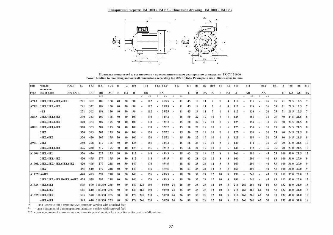
52
��������� ����� IM 1001 ( IM B3) / Dimension drawing IM 1001 ( IM B3)
������� �������� � ���������� - ����������������� �������� �� ���������� ��� 31606
Power binding to mounting and overall dimensions according to GOST 31606 ������� � �� / Dimensions in mm
���
Type
�����
��� ���
No of poles
���� l30
DIN EN L
l 33
LC
h 31
HD
d 30
AC
l1
E
l 2
EA
l10
B
l 11
BB
l 12 / l 12�
BA
l 13 l31
C
d1
D
d2
DA
d10
K
b1
F
b2
FA
b10
A
b11
AB
b12
AA
b31 h
H
h5
GA
h6
GC
h10
HA
*** * ** * ** * ** * ** * **
A71A 2I!1,2I!2,4I!1,4I!2 271 302 188 150 40 30 90 - 112 - 25/25 - 11 45 19 11 7 6 4 112 - 138 - 26 75 71 21.5 12.5 7
A71B 2I!1,2I!2,4I!2 291 322 188 150 40 30 90 - 112 - 25/25 - 11 45 19 11 7 6 4 112 - 138 - 26 75 71 21.5 12.5 7
4!1 271 302 188 150 40 30 90 - 112 - 25/25 - 11 45 19 11 7 6 4 112 - 138 - 26 75 71 21.5 12.5 7
A80A
2I!1,4I!1,6I!1
2I!2,4I!2,6I!2
300
320
343
363
207
207
175
175
50
50
40
40
100
100
-
-
130
130
-
-
32/32
32/32
-
-
15
15
50
50
22
22
19
19
10
10
6
6
6
6
125
125
-
-
159
159
-
-
31
31
75
75
80
80
24.5
24.5
21.5
21.5
8
8
A80B
2I!1,4I!1,6I!1
2I!2
4I!2,6I!2
320
350
376
363
393
420
207
207
207
175
175
175
50
50
50
40
40
40
100
100
100
-
-
-
130
130
130
-
-
-
32/32
32/32
32/32
-
-
-
15
15
15
50
50
50
22
22
22
19
19
19
10
10
10
6
6
6
6
6
6
125
125
125
-
-
-
159
159
159
-
-
-
31
31
31
75
75
75
80
80
80
24.5
24.5
24.5
21.5
21.5
21.5
8
8
8
A90L 2I!1
2I!2,4I!1,6I!1
350
376
398
420
217
217
175
175
50
50
40
40
125
125
-
-
155
155
-
-
32/32
32/32
-
-
15
15
56
56
24
24
19
19
10
10
8
8
6
6
140
140
-
-
172
172
-
-
36
36
75
75
90
90
27.0
27.0
21.5
21.5
10
10
A100S
2I!1,4I!0
2I!2,4I!1,4I!2
376
420
426
475
227
277
175
175
60
60
40
50
112
112
-
-
148
148
-
-
43/43
45/45
-
-
18
18
63
63
28
28
19
24
12
12
8
8
6
8
160
160
-
-
196
200
-
-
43
40
75
83
100
100
31.0
31.0
21.5
27.0
12
9
A100L 2I!1,2I!2,4I!1,6I!1,6I!2
4I!2
420
455
475
510
277
277
218
218
60
60
50
50
140
140
-
-
176
176
-
-
45/45
45/45
-
-
18
18
63
63
28
28
24
24
12
12
8
8
8
8
160
160
-
-
200
200
-
-
40
40
83
83
100
100
31.0
31.0
27.0
27.0
9
9
A112M A6I!1 440 493 297 218 80 50 140 - 176 - 43/43 - 18 70 32 24 12 10 8 190 - 240 - 43 83 112 35.0 27.0 12
2I!1,2I!2,4I!1,"6I!1,#6I!2 475 528 297 218 80 50 140 - 176 - 43/43 - 18 70 32 24 12 10 8 190 - 240 - 43 83 112 35,0 27.0 12
A132S 4I!1,6I!1
4I!2,6I!2
505
545
570
610
310/330
310/330
255
255
80
80
60
60
140
140
226
266
190
190
-
-
50/50
50/50
24
24
25
25
89
89
38
38
28
28
12
12
10
10
8
8
216
216
260
260
266
266
62
62
50
50
83
83
132
132
41.0
41.0
31.0
31.0
18
18
A132M 2I!1,2I!2 505 570 310/330 255 80 60 178 226 230 - 50/50 24 26 89 38 28 12 10 8 216 260 266 62 50 83 132 41.0 31.0 18
4I!1,6I!1 545 610 310/330 255 80 60 178 266 230 - 50/50 24 26 89 38 28 12 10 8 216 260 266 62 50 83 132 41.0 31.0 18
* - ��� �������� � ������� �� ������/ version with attached feet;
** - ��� �������� � ������� �� ������/ version with screwed feet;
*** - ��� �������� ������ �� ��������/������/ version for stator frame for cast iron/alluminium
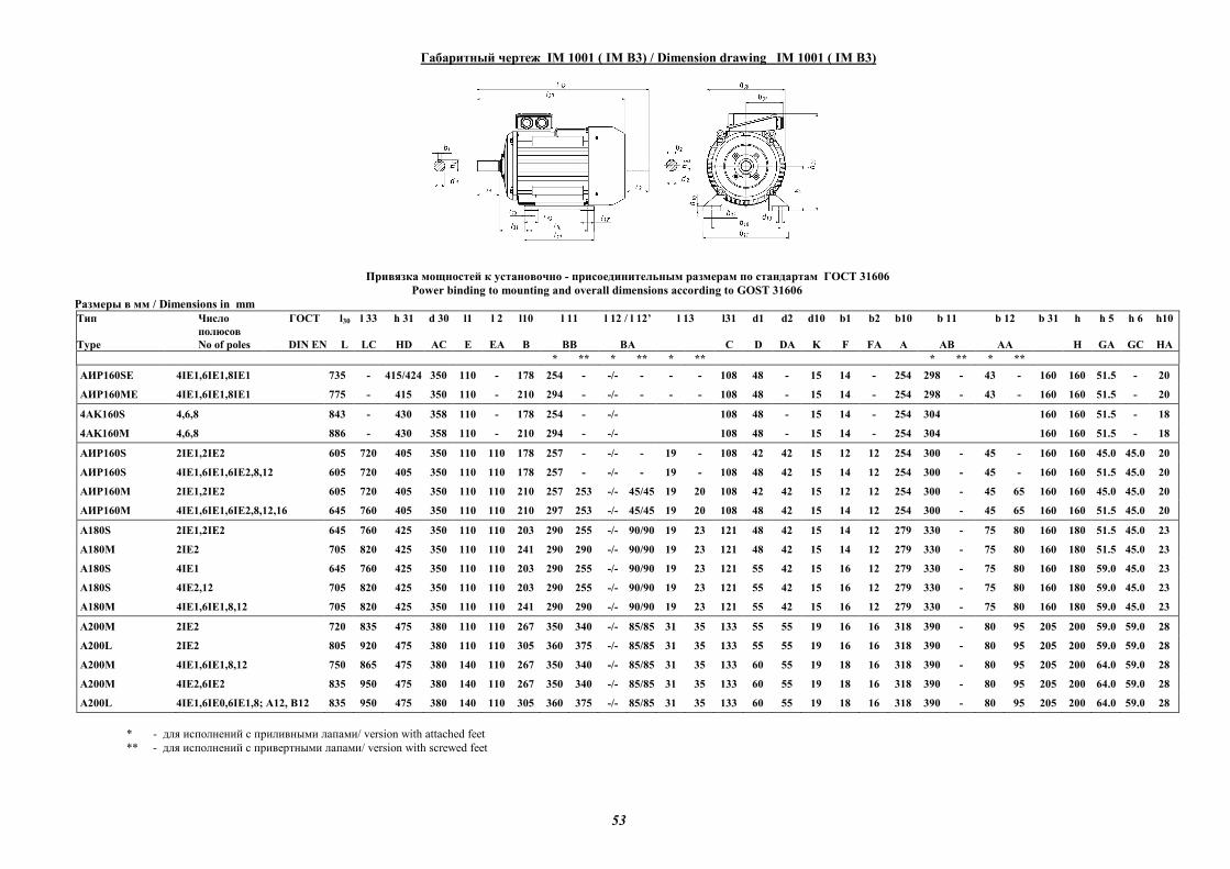
53
Габаритный чертеж IM 1001 ( IM B3) / Dimension drawing IM 1001 ( IM B3)
Привязка мощностей к установочно - присоединительным размерам по стандартам ГОСТ 31606
Power binding to mounting and overall dimensions according to GOST 31606
Размеры в мм / Dimensions in mm
Тип
Type
Число
полюсов
No of poles
ГОСТ l30
DIN EN L
l 33
LC
h 31
HD
d 30
AC
l1
E
l 2
EA
l10
B
l 11
BB
l 12 / l 12’
BA
l 13
l31
C
d1
D
d2
DA
d10
K
b1
F
b2
FA
b10
A
b 11
AB
b 12
AA
b 31
h
H
h 5
GA
h 6
GC
h10
HA
* ** * ** * ** * ** * **
АИР160SE 4IЕ1,6IЕ1,8IЕ1 735 - 415/424 350 110 - 178 254 - -/- - - - 108 48 - 15 14 - 254 298 - 43 - 160 160 51.5 - 20
АИР160ME 4IЕ1,6IЕ1,8IЕ1 775 - 415 350 110 - 210 294 - -/- - - - 108 48 - 15 14 - 254 298 - 43 - 160 160 51.5 - 20
4AK160S 4,6,8 843 - 430 358 110 - 178 254 - -/- 108 48 - 15 14 - 254 304 160 160 51.5 - 18
4AK160M 4,6,8 886 - 430 358 110 - 210 294 - -/- 108 48 - 15 14 - 254 304 160 160 51.5 - 18
АИР160S 2IЕ1,2IЕ2 605 720 405 350 110 110 178 257 - -/- - 19 - 108 42 42 15 12 12 254 300 - 45 - 160 160 45.0 45.0 20
АИР160S 4IE1,6IE1,6IE2,8,12 605 720 405 350 110 110 178 257 - -/- - 19 - 108 48 42 15 14 12 254 300 - 45 - 160 160 51.5 45.0 20
АИР160M 2IЕ1,2IЕ2 605 720 405 350 110 110 210 257 253 -/- 45/45 19 20 108 42 42 15 12 12 254 300 - 45 65 160 160 45.0 45.0 20
АИР160M 4IE1,6IE1,6IE2,8,12,16 645 760 405 350 110 110 210 297 253 -/- 45/45 19 20 108 48 42 15 14 12 254 300 - 45 65 160 160 51.5 45.0 20
А180S 2IЕ1,2IЕ2 645 760 425 350 110 110 203 290 255 -/- 90/90 19 23 121 48 42 15 14 12 279 330 - 75 80 160 180 51.5 45.0 23
А180M 2IЕ2 705 820 425 350 110 110 241 290 290 -/- 90/90 19 23 121 48 42 15 14 12 279 330 - 75 80 160 180 51.5 45.0 23
А180S 4IE1 645 760 425 350 110 110 203 290 255 -/- 90/90 19 23 121 55 42 15 16 12 279 330 - 75 80 160 180 59.0 45.0 23
А180S 4IE2,12 705 820 425 350 110 110 203 290 255 -/- 90/90 19 23 121 55 42 15 16 12 279 330 - 75 80 160 180 59.0 45.0 23
А180M 4IE1,6IE1,8,12 705 820 425 350 110 110 241 290 290 -/- 90/90 19 23 121 55 42 15 16 12 279 330 - 75 80 160 180 59.0 45.0 23
A200M 2IЕ2 720 835 475 380 110 110 267 350 340 -/- 85/85 31 35 133 55 55 19 16 16 318 390 - 80 95 205 200 59.0 59.0 28
A200L 2IЕ2 805 920 475 380 110 110 305 360 375 -/- 85/85 31 35 133 55 55 19 16 16 318 390 - 80 95 205 200 59.0 59.0 28
A200M 4IE1,6IE1,8,12 750 865 475 380 140 110 267 350 340 -/- 85/85 31 35 133 60 55 19 18 16 318 390 - 80 95 205 200 64.0 59.0 28
A200M 4IE2,6IE2 835 950 475 380 140 110 267 350 340 -/- 85/85 31 35 133 60 55 19 18 16 318 390 - 80 95 205 200 64.0 59.0 28
A200L 4IE1,6IЕ0,6IE1,8; А12, В12 835 950 475 380 140 110 305 360 375 -/- 85/85 31 35 133 60 55 19 18 16 318 390 - 80 95 205 200 64.0 59.0 28
* - для исполнений с приливными лапами/ version with attached feet
** - для исполнений с привертными лапами/ version with screwed feet
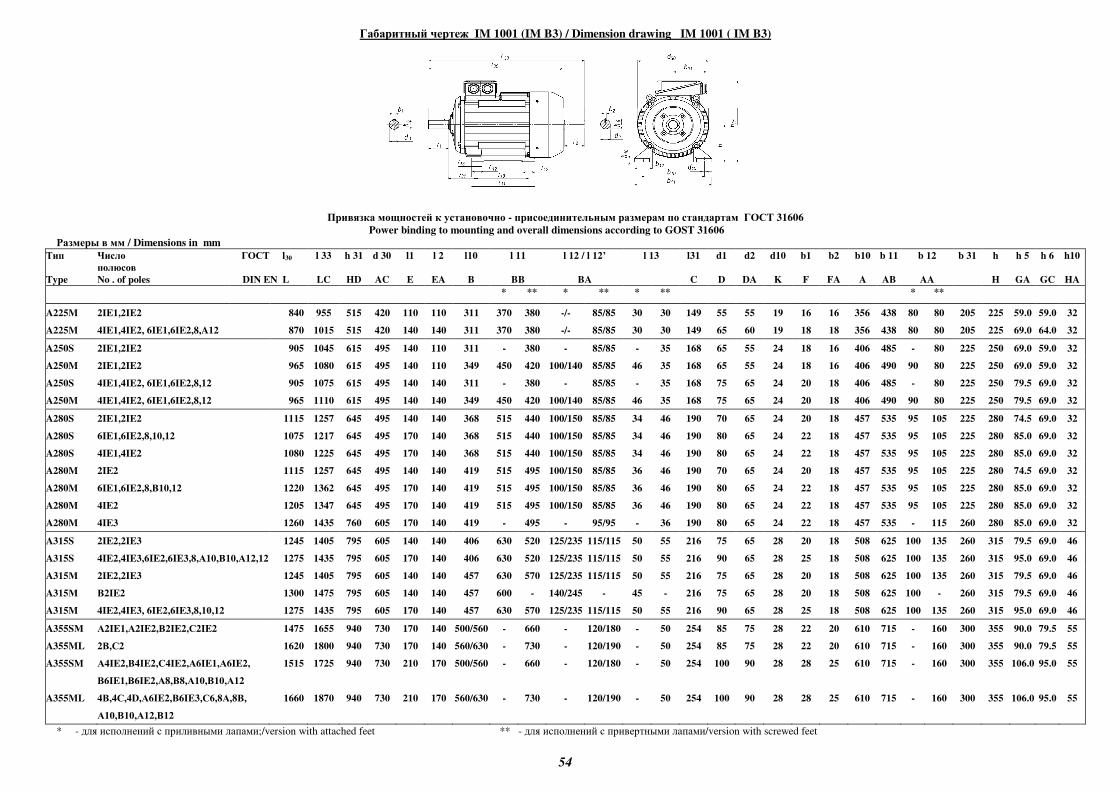
54
Габаритный чертеж IM 1001 (IM B3) / Dimension drawing IM 1001 ( IM B3)
Привязка мощностей к установочно - присоединительным размерам по стандартам ГОСТ 31606
Power binding to mounting and overall dimensions according to GOST 31606
Размеры в мм / Dimensions in mm
Тип
Type
Число
полюсов
No . of poles
ГОСТ l30
DIN EN L
l 33
LC
h 31
HD
d 30
AC
l1
E
l 2
EA
l10
B
l 11
BB
l 12 / l 12’
BA
l 13
l31
C
d1
D
d2
DA
d10
K
b1
F
b2
FA
b10
A
b 11
AB
b 12
AA
b 31
h
H
h 5
GA
h 6
GC
h10
HA
* ** * ** * ** * **
A225M 2IE1,2IE2 840 955 515 420 110 110 311 370 380 -/- 85/85 30 30 149 55 55 19 16 16 356 438 80 80 205 225 59.0 59.0 32
A225M 4IE1,4IE2, 6IE1,6IE2,8,A12 870 1015 515 420 140 140 311 370 380 -/- 85/85 30 30 149 65 60 19 18 18 356 438 80 80 205 225 69.0 64.0 32
A250S 2IE1,2IE2 905 1045 615 495 140 110 311 - 380 - 85/85 - 35 168 65 55 24 18 16 406 485 - 80 225 250 69.0 59.0 32
A250M 2IE1,2IE2 965 1080 615 495 140 110 349 450 420 100/140 85/85 46 35 168 65 55 24 18 16 406 490 90 80 225 250 69.0 59.0 32
A250S 4IE1,4IE2, 6IE1,6IE2,8,12 905 1075 615 495 140 140 311 - 380 - 85/85 - 35 168 75 65 24 20 18 406 485 - 80 225 250 79.5 69.0 32
A250M 4IE1,4IE2, 6IE1,6IE2,8,12 965 1110 615 495 140 140 349 450 420 100/140 85/85 46 35 168 75 65 24 20 18 406 490 90 80 225 250 79.5 69.0 32
A280S 2IE1,2IE2 1115 1257 645 495 140 140 368 515 440 100/150 85/85 34 46 190 70 65 24 20 18 457 535 95 105 225 280 74.5 69.0 32
A280S 6IE1,6IE2,8,10,12 1075 1217 645 495 170 140 368 515 440 100/150 85/85 34 46 190 80 65 24 22 18 457 535 95 105 225 280 85.0 69.0 32
A280S 4IE1,4IE2 1080 1225 645 495 170 140 368 515 440 100/150 85/85 34 46 190 80 65 24 22 18 457 535 95 105 225 280 85.0 69.0 32
A280M 2IE2 1115 1257 645 495 140 140 419 515 495 100/150 85/85 36 46 190 70 65 24 20 18 457 535 95 105 225 280 74.5 69.0 32
A280M 6IE1,6IE2,8,В10,12 1220 1362 645 495 170 140 419 515 495 100/150 85/85 36 46 190 80 65 24 22 18 457 535 95 105 225 280 85.0 69.0 32
A280M 4IE2 1205 1347 645 495 170 140 419 515 495 100/150 85/85 36 46 190 80 65 24 22 18 457 535 95 105 225 280 85.0 69.0 32
A280M 4IE3 1260 1435 760 605 170 140 419 - 495 - 95/95 - 36 190 80 65 24 22 18 457 535 - 115 260 280 85.0 69.0 32
A315S 2IE2,2IE3 1245 1405 795 605 140 140 406 630 520 125/235 115/115 50 55 216 75 65 28 20 18 508 625 100 135 260 315 79.5 69.0 46
A315S 4IE2,4IE3,6IE2,6IE3,8,А10,В10,А12,12 1275 1435 795 605 170 140 406 630 520 125/235 115/115 50 55 216 90 65 28 25 18 508 625 100 135 260 315 95.0 69.0 46
A315М 2IE2,2IE3 1245 1405 795 605 140 140 457 630 570 125/235 115/115 50 55 216 75 65 28 20 18 508 625 100 135 260 315 79.5 69.0 46
A315М В2IE2 1300 1475 795 605 140 140 457 600 - 140/245 - 45 - 216 75 65 28 20 18 508 625 100 - 260 315 79.5 69.0 46
A315M 4IE2,4IE3, 6IE2,6IE3,8,10,12 1275 1435 795 605 170 140 457 630 570 125/235 115/115 50 55 216 90 65 28 25 18 508 625 100 135 260 315 95.0 69.0 46
A355SМ А2IE1,А2IE2,В2IE2,С2IE2 1475 1655 940 730 170 140 500/560 - 660 - 120/180 - 50 254 85 75 28 22 20 610 715 - 160 300 355 90.0 79.5 55
A355ML 2В,С2 1620 1800 940 730 170 140 560/630 - 730 - 120/190 - 50 254 85 75 28 22 20 610 715 - 160 300 355 90.0 79.5 55
A355SM А4IE2,В4IE2,С4IE2,А6IE1,А6IE2,
В6IE1,В6IE2,А8,В8,А10,В10,А12
1515 1725 940 730 210 170 500/560 - 660 - 120/180 - 50 254 100 90 28 28 25 610 715 - 160 300 355 106.0 95.0 55
A355ML 4В,4С,4D,А6IE2,В6IE3,С6,8А,8В,
А10,В10,А12,В12
1660 1870 940 730 210 170 560/630 - 730 - 120/190 - 50 254 100 90 28 28 25 610 715 - 160 300 355 106.0 95.0 55
* - для исполнений с приливными лапами;/version with attached feet ** - для исполнений с привертными лапами/version with screwed feet
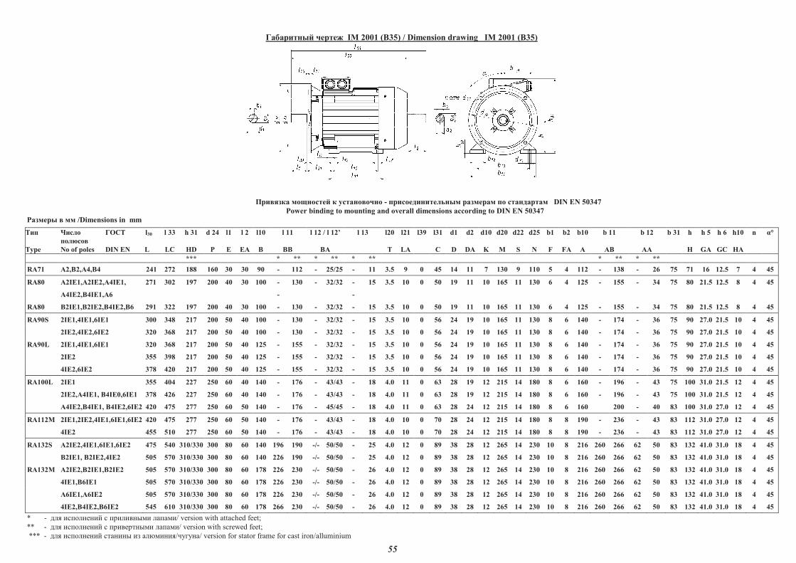
55
��������� ����� IM 2001 (B35) / Dimension drawing IM 2001 (B35)
������� �������� � ���������� - ����������������� �������� �� ���������� DIN EN 50347
Power binding to mounting and overall dimensions according to DIN EN 50347
������� � �� /Dimensions in mm
���
Type
�����
�������
No of poles
�� � l30
DIN EN L
l 33
LC
h 31
HD
d 24
�
l1
E
l 2
EA
l10
B
l 11
BB
l 12 / l 12�
BA
l 13 l20
T
l21
LA
l39 l31
C
d1
D
d2
DA
d10
K
d20
M
d22
S
d25
N
b1
F
b2
FA
b10
A
b 11
AB
b 12
AA
b 31 h
H
h 5
GA
h 6
GC
h10
HA
n !°
*** * ** * ** * ** * ** * **
RA71 "2,#2,"4,#4 241 272 188 160 30 30 90 - 112 - 25/25 - 11 3.5 9 0 45 14 11 7 130 9 110 5 4 112 - 138 - 26 75 71 16 12.5 7 4 45
RA80 "2I$1,"2I$2,"4I$1, 271 302 197 200 40 30 100 - 130 - 32/32 - 15 3.5 10 0 50 19 11 10 165 11 130 6 4 125 - 155 - 34 75 80 21.5 12.5 8 4 45
"4I$2,#4I$1,"6 - -
RA80 #2I$1,#2I$2,#4I$2,#6 291 322 197 200 40 30 100 - 130 - 32/32 - 15 3.5 10 0 50 19 11 10 165 11 130 6 4 125 - 155 - 34 75 80 21.5 12.5 8 4 45
RA90S 2I$1,4I$1,6I$1 300 348 217 200 50 40 100 - 130 - 32/32 - 15 3.5 10 0 56 24 19 10 165 11 130 8 6 140 - 174 - 36 75 90 27.0 21.5 10 4 45
2I$2,4I$2,6I$2 320 368 217 200 50 40 100 - 130 - 32/32 - 15 3.5 10 0 56 24 19 10 165 11 130 8 6 140 - 174 - 36 75 90 27.0 21.5 10 4 45
RA90L 2I$1,4I$1,6I$1 320 368 217 200 50 40 125 - 155 - 32/32 - 15 3.5 10 0 56 24 19 10 165 11 130 8 6 140 - 174 - 36 75 90 27.0 21.5 10 4 45
2I$2 355 398 217 200 50 40 125 - 155 - 32/32 - 15 3.5 10 0 56 24 19 10 165 11 130 8 6 140 - 174 - 36 75 90 27.0 21.5 10 4 45
4I$2,6I$2 378 420 217 200 50 40 125 - 155 - 32/32 - 15 3.5 10 0 56 24 19 10 165 11 130 8 6 140 - 174 - 36 75 90 27.0 21.5 10 4 45
RA100L 2I$1 355 404 227 250 60 40 140 - 176 - 43/43 - 18 4.0 11 0 63 28 19 12 215 14 180 8 6 160 - 196 - 43 75 100 31.0 21.5 12 4 45
2I$2,A4I$1, B4I$0,6I$1
A4I$2,#4I$1, #4I$2,6I$2
378
420
426
475
227
277
250
250
60
60
40
50
140
140
-
-
176
176
-
-
43/43
45/45
-
-
18
18
4.0
4.0
11
11
0
0
63
63
28
28
19
24
12
12
215
215
14
14
180
180
8
8
6
6
160
160
- 196
200
-
-
43
40
75
83
100
100
31.0
31.0
21.5
27.0
12
12
4
4
45
45
RA112M
2I$1,2I$2,4I$1,6I$1,6I$2
4I$2
420
455
475
510
277
277
250
250
60
60
50
50
140
140
-
-
176
176
-
-
43/43
43/43
-
-
18
18
4.0
4.0
10
10
0
0
70
70
28
28
24
24
12
12
215
215
14
14
180
180
8
8
8
8
190
190
-
-
236
236
-
-
43
43
83
83
112
112
31.0
31.0
27.0
27.0
12
12
4
4
45
45
RA132S
A2I$2,4I$1,6I$1,6I$2
#2I$1, #2I$2,4I$2
475
505
540
570
310/330
310/330
300
300
80
80
60
60
140
140
196
226
190
190
-/-
-/-
50/50
50/50
-
-
25
25
4.0
4.0
12
12
0
0
89
89
38
38
28
28
12
12
265
265
14
14
230
230
10
10
8
8
216
216
260
260
266
266
62
62
50
50
83
83
132
132
41.0
41.0
31.0
31.0
18
18
4
4
45
45
RA132M A2I$2,#2I$1,#2I$2
4I$1,#6I$1
505
505
570
570
310/330
310/330
300
300
80
80
60
60
178
178
226
226
230
230
-/-
-/-
50/50
50/50
-
-
26
26
4.0
4.0
12
12
0
0
89
89
38
38
28
28
12
12
265
265
14
14
230
230
10
10
8
8
216
216
260
260
266
266
62
62
50
50
83
83
132
132
41.0
41.0
31.0
31.0
18
18
4
4
45
45
"6I$1,"6I$2
4I$2,#4I$2,#6I$2
505
545
570
610
310/330
310/330
300
300
80
80
60
60
178
178
226
266
230
230
-/-
-/-
50/50
50/50
-
-
26
26
4.0
4.0
12
12
0
0
89
89
38
38
28
28
12
12
265
265
14
14
230
230
10
10
8
8
216
216
260
260
266
266
62
62
50
50
83
83
132
132
41.0
41.0
31.0
31.0
18
18
4
4
45
45
* - ��� �������� � ������� �� ������/ version with attached feet;
** - ��� �������� � ������� �� ������/ version with screwed feet;
*** - ��� �������� ������ �� ��������/������/ version for stator frame for cast iron/alluminium
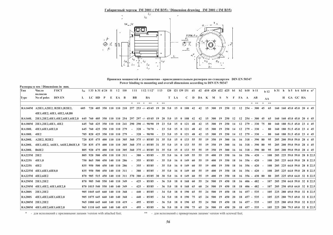
56
��������� ����� IM 2001 ( IM B35) / Dimension drawing IM 2001 ( IM B35)
������� �������� � ���������� - ����������������� �������� �� ���������� DIN EN 50347
Power binding to mounting and overall dimensions according to DIN EN 50347
������� � �� / Dimensions in mm.
���
Type
�����
�������
No of poles
�� � l30
DIN EN L
l 33
LC
h 31
HD
d 24
�
l1
E
l 2
EA
l10
B
l 11
BB
l 12 / l 12�
BA
l 13 l20
T
l21
LA
l39 l31
C
d1
D
d2
DA
d10
K
d20
M
d22
S
d25
N
b1
F
b2
FA
b10
A
b 11
AB
b 12
AA
b 31 h
H
h 5
GA
h 6
GC
h10
HA
n !°
* ** * ** * ** * ** * **
RA160M "2IE1,"2IE2, #2IE1,#2IE2, 605
4IE1,4IE2, 6IE1, 6IE2,"8,#8
720 405 350 110 110 210 257 253 -/- 45/45 19 20 5.0 15 0 108 42 42 15 300 19 250 12 12 254 - 300 45 65 160 160 45.0 45.0 20 4 45
RA160L 2IE1,2IE2,4IE1,4IE2,6IE1,6IE2,8 645 760 405 350 110 110 254 297 297 -/- 45/45 19 20 5.0 15 0 108 42 42 15 300 19 250 12 12 254 - 300 45 65 160 160 45.0 45.0 20 4 45
RA180M 2IE1,2IE2,4IE1, 4IE2 645 760 425 350 110 110 241 290 290 -/- 90/90 19 23 5.0 15 0 121 48 42 15 300 19 250 14 12 279 - 330 75 80 160 180 51.5 45.0 23 4 45
RA180L 4IE1,6IE1,6IE2,8 645 760 425 350 110 110 279 - 328 - 70/70 - 23 5.0 15 0 121 48 42 15 300 19 250 14 12 279 - 330 - 80 160 180 51.5 45.0 23 4 45
RA180L 4IE2 705 820 425 350 110 110 279 - 328 - 90/90 - 23 5.0 15 0 121 48 42 15 300 19 250 14 12 279 - 330 - 80 160 180 51.5 45.0 23 4 45
RA200L "2IE2, #2IE2 720 835 475 400 110 110 305 360 375 -/- 85/85 31 35 5.0 15 0 133 55 55 19 350 19 300 16 16 318 - 390 80 95 205 200 59.0 59.0 28 4 45
RA200L 4IE1,4IE2, "6IE1, "6IE2,B6IE1,8 720 835 475 400 110 110 305 360 375 -/- 85/85 31 35 5.0 15 0 133 55 55 19 350 19 300 16 16 318 - 390 80 95 205 200 59.0 59.0 28 4 45
RA200L B6IE2 805 920 475 400 110 110 305 360 375 -/- 85/85 31 35 5.0 15 0 133 55 55 19 350 19 300 16 16 318 - 390 80 95 205 200 59.0 59.0 28 4 45
RA225M 2IE2 805 920 500 450 110 110 311 - 380 - 85/85 - 35 5.0 16 0 149 55 55 19 400 19 350 16 16 356 - 420 - 108 205 225 59.0 59.0 28 8 22.5
RA225S 4IE1,8 750 865 500 450 140 110 286 - 355 - 85/85 - 35 5.0 16 0 149 60 55 19 400 19 350 18 16 356 - 420 - 108 205 225 64.0 59.0 28 8 22.5
RA225S 4IE2 835 950 500 450 140 110 286 - 355 - 85/85 - 35 5.0 16 0 149 60 55 19 400 19 350 18 16 356 - 420 - 108 205 225 64.0 59.0 28 8 22.5
RA225M 4IE1,6IE1,6IE0,8 835 950 500 450 140 110 311 - 380 - 85/85 - 35 5.0 16 0 149 60 55 19 400 19 350 18 16 356 - 420 - 108 205 225 64.0 59.0 28 8 22.5
RA225M 4IE2,6IE2 870 985 515 450 140 110 311 370 380 -/- 85/85 30 30 5.0 16 0 149 60 55 19 400 19 350 18 16 356 - 438 80 80 205 225 69.0 64.0 32 8 22.5
RA250M 2IE1,2IE2 870 985 540 550 140 110 349 - 425 - 85/85 - 36 5.0 18 0 168 60 55 24 500 19 450 18 16 406 - 482 - 107 205 250 64.0 59.0 32 8 22.5
RA250M 4IE1,4IE2, 6IE1,6IE2,8 870 1015 540 550 140 140 349 - 425 - 85/85 - 36 5.0 18 0 168 65 60 24 500 19 450 18 18 406 - 482 - 107 205 250 69.0 64.0 32 8 22.5
RA280S 2IE1,2IE2 905 1045 645 660 140 110 368 - 440 - 85/85 - 34 5.0 18 0 190 65 55 24 500 19 450 18 16 457 - 535 - 105 225 280 69.0 59.0 32 8 22.5
RA280S 4IE1,4IE2,6IE1,6IE2,8 905 1075 645 660 140 140 368 - 440 - 85/85 - 34 5.0 18 0 190 75 65 24 500 19 450 20 18 457 - 535 - 105 225 280 79.5 69.0 32 8 22.5
RA280M 2IE1,2IE2 965 1080 645 660 140 110 419 - 495 - 85/85 - 36 5.0 18 0 190 65 55 24 500 19 450 18 16 457 - 535 - 105 225 280 69.0 59.0 32 8 22.5
RA280M 4IE1,4IE2,6IE1,6IE2,8 965 1110 645 660 140 140 419 - 495 - 85/85 - 36 5.0 18 0 190 75 65 24 500 19 450 20 18 457 - 535 - 105 225 280 79.5 69.0 32 8 22.5
* - ��� �������� � ������� �� ������ /version with attached feet; ** - ��� �������� � ������� �� ������/ version with screwed feet;
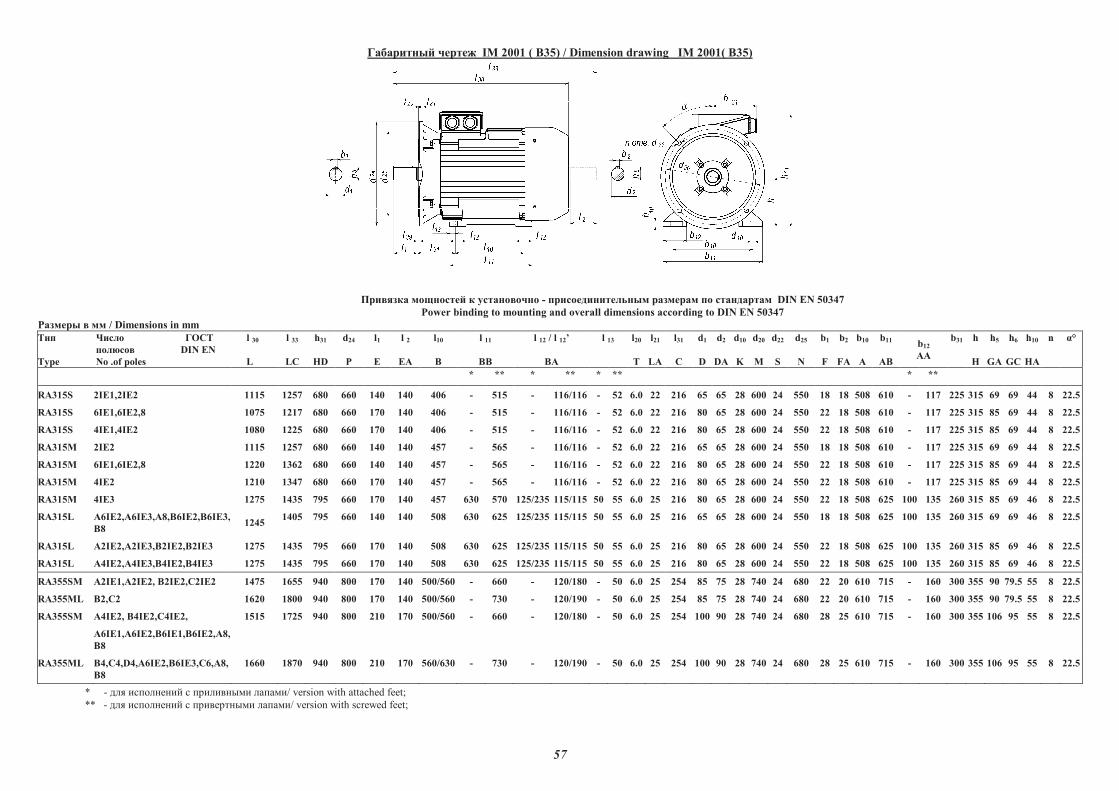
57
��������� ����� IM 2001 ( B35) / Dimension drawing IM 2001( B35)
������� �������� � ���������� - ����������������� �������� �� ���������� DIN EN 50347
Power binding to mounting and overall dimensions according to DIN EN 50347
������� � �� / Dimensions in mm
���
Type
����� ����
��� ��� DIN EN
No .of poles
l 30
L
l 33
LC
h31
HD
d24
P
l1
E
l 2
EA
l10
B
l 11
BB
l 12 / l 12�
BA
l 13 l20
T
l21
LA
l31
C
d1
D
d2
DA
d10
K
d20
M
d22
S
d25
N
b1
F
b2
FA
b10
A
b11
AB
b12
AA
b31 h
H
h5
GA
h6
GC
h10
HA
n !°
* ** * ** * ** * **
RA315S 2IE1,2IE2 1115 1257 680 660 140 140 406 - 515 - 116/116 - 52 6.0 22 216 65 65 28 600 24 550 18 18 508 610 - 117 225 315 69 69 44 8 22.5
RA315S 6IE1,6IE2,8 1075 1217 680 660 170 140 406 - 515 - 116/116 - 52 6.0 22 216 80 65 28 600 24 550 22 18 508 610 - 117 225 315 85 69 44 8 22.5
RA315S 4IE1,4IE2 1080 1225 680 660 170 140 406 - 515 - 116/116 - 52 6.0 22 216 80 65 28 600 24 550 22 18 508 610 - 117 225 315 85 69 44 8 22.5
RA315M 2IE2 1115 1257 680 660 140 140 457 - 565 - 116/116 - 52 6.0 22 216 65 65 28 600 24 550 18 18 508 610 - 117 225 315 69 69 44 8 22.5
RA315M 6IE1,6IE2,8 1220 1362 680 660 140 140 457 - 565 - 116/116 - 52 6.0 22 216 80 65 28 600 24 550 22 18 508 610 - 117 225 315 85 69 44 8 22.5
RA315M 4IE2 1210 1347 680 660 170 140 457 - 565 - 116/116 - 52 6.0 22 216 80 65 28 600 24 550 22 18 508 610 - 117 225 315 85 69 44 8 22.5
RA315M 4IE3 1275 1435 795 660 170 140 457 630 570 125/235 115/115 50 55 6.0 25 216 80 65 28 600 24 550 22 18 508 625 100 135 260 315 85 69 46 8 22.5
RA315L "6IE2,"6IE3,A8,#6IE2,#6IE3,
#8 1245
1405 795 660 140 140 508 630 625 125/235 115/115 50 55 6.0 25 216 65 65 28 600 24 550 18 18 508 625 100 135 260 315 69 69 46 8 22.5
RA315L "2IE2,"2IE3,#2IE2,#2IE3 1275 1435 795 660 170 140 508 630 625 125/235 115/115 50 55 6.0 25 216 80 65 28 600 24 550 22 18 508 625 100 135 260 315 85 69 46 8 22.5
RA315L "4IE2,"4IE3,#4IE2,#4IE3 1275 1435 795 660 170 140 508 630 625 125/235 115/115 50 55 6.0 25 216 80 65 28 600 24 550 22 18 508 625 100 135 260 315 85 69 46 8 22.5
RA355SM "2IE1,"2IE2, #2IE2,�2IE2 1475 1655 940 800 170 140 500/560 - 660 - 120/180 - 50 6.0 25 254 85 75 28 740 24 680 22 20 610 715 - 160 300 355 90 79.5 55 8 22.5
RA355ML #2,�2 1620 1800 940 800 170 140 500/560 - 730 - 120/190 - 50 6.0 25 254 85 75 28 740 24 680 22 20 610 715 - 160 300 355 90 79.5 55 8 22.5
RA355SM "4IE2, #4IE2,�4IE2,
"6IE1,"6IE2,#6IE1,#6IE2,"8,
#8
1515 1725 940 800 210 170 500/560 - 660 - 120/180 - 50 6.0 25 254 100 90 28 740 24 680 28 25 610 715 - 160 300 355 106 95 55 8 22.5
RA355ML #4,�4,D4,"6IE2,#6IE3,�6,"8,
#8
1660 1870 940 800 210 170 560/630 - 730 - 120/190 - 50 6.0 25 254 100 90 28 740 24 680 28 25 610 715 - 160 300 355 106 95 55 8 22.5
--
* - ��� �������� � ������� �� ������/ version with attached feet;
** - ��� �������� � ������� �� ������/ version with screwed feet;
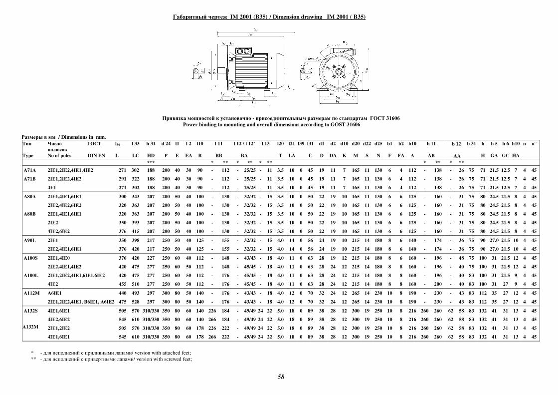
58
Габаритный чертеж IM 2001 (B35) / Dimension drawing IM 2001 ( B35)
Привязка мощностей к установочно - присоединительным размерам по стандартам ГОСТ 31606
Power binding to mounting and overall dimensions according to GOST 31606
Размеры в мм / Dimensions in mm.
Тип
Type
Число
полюсов
No of poles
ГОСТ l30
DIN EN L
l 33
LC
h 31
HD
d 24
Р
l1
E
l 2
EA
l10
B
l 11
BB
l 12 / l 12’
BA
l 13
l20
T
l21
LA
l39
l31
C
d1
D
d2
DA
d10
K
d20
M
d22
S
d25
N
b1
F
b2
FA
b10
A
b 11
AB
b 12
AA
b 31
h
H
h 5
GA
h 6
GC
h10
HA
n α°
*** * ** * ** * ** * ** * **
A71A 2IЕ1,2IЕ2,4IЕ1,4IЕ2 271 302 188 200 40 30 90 - 112 - 25/25 - 11 3.5 10 0 45 19 11 7 165 11 130 6 4 112 - 138 - 26 75 71 21.5 12.5 7 4 45
A71B 2IЕ1,2IЕ2,4IЕ2 291 322 188 200 40 30 90 - 112 - 25/25 - 11 3.5 10 0 45 19 11 7 165 11 130 6 4 112 - 138 - 26 75 71 21.5 12.5 7 4 45
4Е1 271 302 188 200 40 30 90 - 112 - 25/25 - 11 3.5 10 0 45 19 11 7 165 11 130 6 4 112 - 138 - 26 75 71 21.5 12.5 7 4 45
A80A
2IЕ1,4IЕ1,6IЕ1
2IЕ2,4IЕ2,6IЕ2
300
320
343
363
207
207
200
200
50
50
40
40
100
100
-
-
130
130
-
-
32/32
32/32
-
-
15
15
3.5
3.5
10
10
0
0
50
50
22
22
19
19
10
10
165
165
11
11
130
130
6
6
6
6
125
125
-
-
160
160
-
-
31
31
75
75
80
80
24.5
24.5
21.5
21.5
8
8
4
4
45
45
A80B
2IЕ1,4IЕ1,6IЕ1
2IЕ2
4IЕ2,6IЕ2
320
350
376
363
393
415
207
207
207
200
200
200
50
50
50
40
40
40
100
100
100
-
-
-
130
130
130
-
-
-
32/32
32/32
32/32
-
-
-
15
15
15
3.5
3.5
3.5
10
10
10
0
0
0
50
50
50
22
22
22
19
19
19
10
10
10
165
165
165
11
11
11
130
130
130
6
6
6
6
6
6
125
125
125
-
-
-
160
160
160
-
-
-
31
31
31
75
75
75
80
80
80
24.5
24.5
24.5
21.5
21.5
21.5
8
8
8
4
4
4
45
45
45
A90L 2IЕ1
2IЕ2,4IЕ1,6IЕ1
350
376
398
420
217
217
250
250
50
50
40
40
125
125
-
-
155
155
-
-
32/32
32/32
-
-
15
15
4.0
4.0
14
14
0
0
56
56
24
24
19
19
10
10
215
215
14
14
180
180
8
8
6
6
140
140
-
-
174
174
-
-
36
36
75
75
90
90
27.0
27.0
21.5
21.5
10
10
4
4
45
45
A100S
2IЕ1,4IЕ0
2IЕ2,4IЕ1,4IЕ2
376
420
420
475
227
277
250
250
60
60
40
50
112
112
-
-
148
148
-
-
43/43
45/45
-
-
18
18
4.0
4.0
11
11
0
0
63
63
28
28
19
24
12
12
215
215
14
14
180
180
8
8
6
8
160
160
-
-
196
196
-
-
48
40
75
75
100
100
31
31
21.5
21.5
12
12
4
4
45
45
A100L 2IЕ1,2IЕ2,4IЕ1,6IЕ1,6IЕ2
4IЕ2
420
455
475
510
277
277
250
250
60
60
50
50
112
112
-
-
176
176
-
-
45/45
45/45
-
-
18
18
4.0
4.0
11
11
0
0
63
63
28
28
24
24
12
12
215
215
14
14
180
180
8
8
8
8
160
160
-
-
196
200
-
-
40
40
83
83
100
100
31
31
21.5
27
9
9
4
4
45
45
A112M A6IЕ1 440 493 297 300 80 50 140 - 176 - 43/43 - 18 4.0 12 0 70 32 24 12 265 14 230 10 8 190 - 230 - 43 83 112 35 27 12 4 45
2IЕ1,2IЕ2,4IЕ1, В6IЕ1, А6IЕ2 475 528 297 300 80 50 140 - 176 - 43/43 - 18 4.0 12 0 70 32 24 12 265 14 230 10 8 190 - 230 - 43 83 112 35 27 12 4 45
A132S 4IЕ1,6IЕ1
4IЕ2,6IЕ2
505
545
570
610
310/330
310/330
350
350
80
80
60
60
140
140
226
266
184
184
-
-
49/49
49/49
24
24
22
22
5.0
5.0
18
18
0
0
89
89
38
38
28
28
12
12
300
300
19
19
250
250
10
10
8
8
216
216
260
260
260
260
62
62
58
58
83
83
132
132
41
41
31
31
13
13
4
4
45
45
A132M 2IЕ1,2IЕ2
4IЕ1,6IЕ1
505
545
570
610
310/330
310/330
350
350
80
80
60
60
178
178
226
266
222
222
-
-
49/49
49/49
24
24
22
22
5.0
5.0
18
18
0
0
89
89
38
38
28
28
12
12
300
300
19
19
250
250
10
10
8
8
216
216
260
260
260
260
62
62
58
58
83
83
132
132
41
41
31
31
13
13
4
4
45
45
* - для исполнений с приливными лапами/ version with attached feet;
** - для исполнений с привертными лапами/ version with screwed feet;
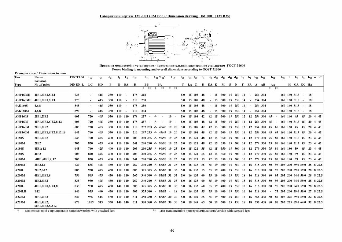
59
Габаритный чертеж IM 2001 ( IM B35) / Dimension drawing IM 2001 ( IM B35)
Привязка мощностей к установочно - присоединительным размерам по стандартам ГОСТ 31606
Power binding to mounting and overall dimensions according to GOST 31606
Размеры в мм / Dimensions in mm.
Тип
Type
Число
полюсов
No .of poles
ГОСТ l 30
DIN EN L
l 33
LC
h31
HD
d24
P
l1
E
l 2
EA
l10
B
l 11
BB
l 12 / l 12’
BA
l 13
l20
T
l21
LA
l31
C
d1
D
d2
DA
d10
K
d20
M
d22
S
d25
N
b1
F
b2
FA
b10
A
b11
AB
b12
AA
b31
h
H
h5
GA
h6
GC
h10
HA
n α°
* ** * ** * ** * **
АИР160SE 4IЕ1,6IЕ1,8IЕ1 735 - 415 350 110 - 178 218 5.0 15 108 48 - 15 300 19 250 14 - 254 304 160 160 51.5 - 18
АИР160ME 4IЕ1,6IЕ1,8IЕ1 775 - 415 350 110 - 210 250 5.0 15 108 48 - 15 300 19 250 14 - 254 304 160 160 51.5 - 18
4AK160S 4,6,8 845 - 415 350 110 - 178 250 5.0 15 108 48 - 15 300 19 250 14 - 254 304 160 160 51.5 - 18
4AK160M 4,6,8 890 - 415 350 110 - 210 294 5.0 15 108 48 - 15 300 19 250 14 - 254 304 160 160 51.5 - 18
АИР160S 2IЕ1,2IЕ2 605 720 405 350 110 110 178 257 - -/- - 19 - 5.0 15 108 42 42 15 300 19 250 12 12 254 300 45 - 160 160 45 45 20 4 45
АИР160S 4IE1,6IE1,6IE2,8;12 605 720 405 350 110 110 178 257 - -/- - 19 - 5.0 15 108 48 42 15 300 19 250 14 12 254 300 45 - 160 160 51.5 45 20 4 45
АИР160M 2IЕ1,2IЕ2 605 720 405 350 110 110 210 257 253 -/- 45/45 19 20 5.0 15 108 42 42 15 300 19 250 12 12 254 300 45 65 160 160 45 45 20 4 45
АИР160M 4IE1,6IE1,6IE2,8,12,16 645 760 405 350 110 110 210 297 253 -/- 45/45 19 20 5.0 15 108 48 42 15 300 19 250 14 12 254 300 45 65 160 160 51.5 45 20 4 45
А180S 2IЕ1,2IЕ2 645 760 425 400 110 110 203 290 255 -/- 90/90 19 23 5.0 15 121 48 42 15 350 19 300 14 12 279 330 75 80 160 180 51.5 45 23 4 45
А180M 2IЕ2 705 820 425 400 110 110 241 290 290 -/- 90/90 19 23 5.0 15 121 48 42 15 350 19 300 14 12 279 330 75 80 160 180 51.5 45 23 4 45
А180S 4IE1; 12 645 760 425 400 110 110 203 290 255 -/- 90/90 19 23 5.0 15 121 55 42 15 350 19 300 16 12 279 330 75 80 160 180 59 45 23 4 45
А180S 4IE2 705 820 425 400 110 110 203 290 255 -/- 90/90 19 23 5.0 15 121 55 42 15 350 19 300 16 12 279 330 75 80 160 180 59 45 23 4 45
А180M 4IE1,6IE1,8, 12 705 820 425 400 110 110 241 290 290 -/- 90/90 19 23 5.0 15 121 55 42 15 350 19 300 16 12 279 330 75 80 160 180 59 45 23 4 45
A200M 2IЕ2,12 720 835 475 450 110 110 267 340 340 -/- 85/85 31 35 5.0 16 133 55 55 19 400 19 350 16 16 318 390 80 95 205 200 59.0 59.0 28 8 22.5
A200L 2IЕ2,А12 805 920 475 450 110 110 305 375 375 -/- 85/85 31 35 5.0 16 133 55 55 19 400 19 350 16 16 318 390 80 95 205 200 59.0 59.0 28 8 22.5
A200M 4IE1,6IE1,8 750 865 475 450 140 110 267 340 340 -/- 85/85 31 35 5.0 16 133 60 55 19 400 19 350 18 16 318 390 80 95 205 200 64.0 59.0 28 8 22.5
A200M 4IE2,6IE2 835 950 475 450 140 110 267 340 340 -/- 85/85 31 35 5.0 16 133 60 55 19 400 19 350 18 16 318 390 80 95 205 200 64.0 59.0 28 8 22.5
A200L 4IE1,6IЕ0,6IE1,8 835 950 475 450 140 110 305 375 375 -/- 85/85 31 35 5.0 16 133 60 55 19 400 19 350 18 16 318 390 80 95 205 200 64.0 59.0 28 8 22.5
A200LB В12 840 955 490 450 110 110 305 375 380 - 85/85 - 18 5.0 16 133 55 55 19 400 19 350 16 16 318 390 - 75 205 200 59.0 59.0 27 8 22.5
A225M 2IE1,2IE2 840 955 515 550 110 110 311 380 380 -/- 85/85 30 30 5.0 16 149 55 55 19 500 19 450 16 16 356 438 80 80 205 225 59.0 59.0 32 8 22.5
A225M 4IE1,4IE2,
6IE1,6IE2,8,A12
870 1015 515 550 140 140 311 380 380 -/- 85/85 30 30 5.0 18 149 65 60 19 500 19 450 18 18 356 438 80 80 205 225 69.0 64.0 32 8 22.5
* - для исполнений с приливными лапами;/version with attached feet ** - для исполнений с привертными лапами/version with screwed feet
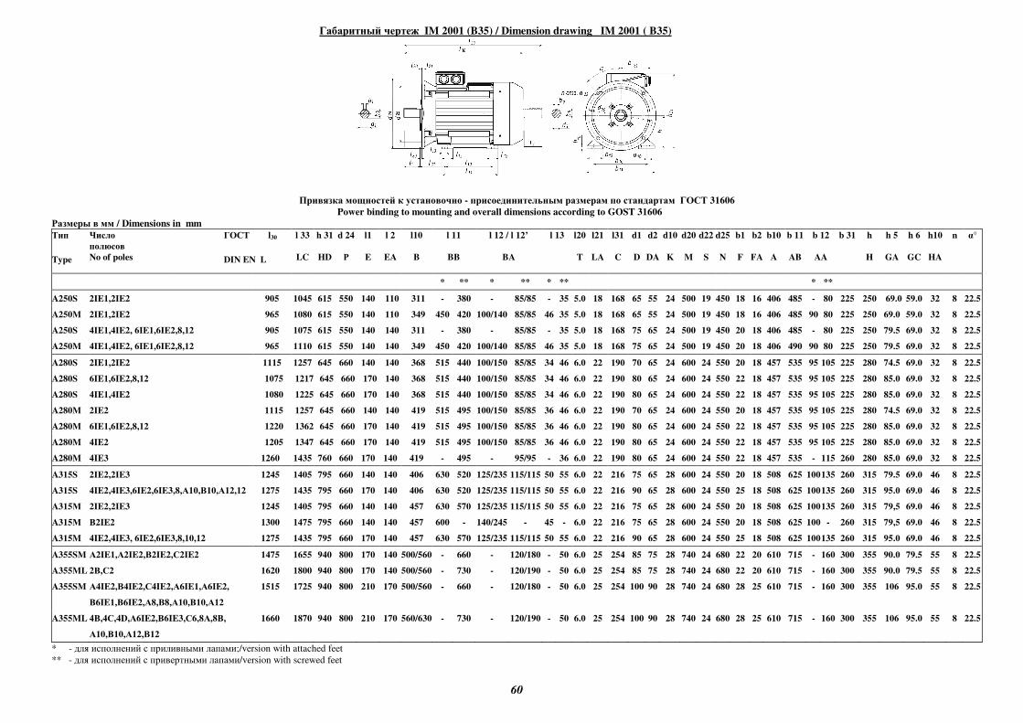
60
Габаритный чертеж IM 2001 (B35) / Dimension drawing IM 2001 ( B35)
Привязка мощностей к установочно - присоединительным размерам по стандартам ГОСТ 31606
Power binding to mounting and overall dimensions according to GOST 31606
Размеры в мм / Dimensions in mm
Тип
Type
Число
полюсов
No of poles
ГОСТ l30
DIN EN L
l 33
LC
h 31
HD
d 24
Р
l1
E
l 2
EA
l10
B
l 11
BB
l 12 / l 12’
BA
l 13
l20
T
l21
LA
l31
C
d1
D
d2
DA
d10
K
d20
M
d22
S
d25
N
b1
F
b2
FA
b10
A
b 11
AB
b 12
AA
b 31
h
H
h 5
GA
h 6
GC
h10
HA
n α°
* ** * ** * ** * **
A250S 2IE1,2IE2 905 1045 615 550 140 110 311 - 380 - 85/85 - 35 5.0 18 168 65 55 24 500 19 450 18 16 406 485 - 80 225 250 69.0 59.0 32 8 22.5
A250M 2IE1,2IE2 965 1080 615 550 140 110 349 450 420 100/140 85/85 46 35 5.0 18 168 65 55 24 500 19 450 18 16 406 485 90 80 225 250 69.0 59.0 32 8 22.5
A250S 4IE1,4IE2, 6IE1,6IE2,8,12 905 1075 615 550 140 140 311 - 380 - 85/85 - 35 5.0 18 168 75 65 24 500 19 450 20 18 406 485 - 80 225 250 79.5 69.0 32 8 22.5
A250M 4IE1,4IE2, 6IE1,6IE2,8,12 965 1110 615 550 140 140 349 450 420 100/140 85/85 46 35 5.0 18 168 75 65 24 500 19 450 20 18 406 490 90 80 225 250 79.5 69.0 32 8 22.5
A280S 2IE1,2IE2 1115 1257 645 660 140 140 368 515 440 100/150 85/85 34 46 6.0 22 190 70 65 24 600 24 550 20 18 457 535 95 105 225 280 74.5 69.0 32 8 22.5
A280S 6IE1,6IE2,8,12 1075 1217 645 660 170 140 368 515 440 100/150 85/85 34 46 6.0 22 190 80 65 24 600 24 550 22 18 457 535 95 105 225 280 85.0 69.0 32 8 22.5
A280S 4IE1,4IE2 1080 1225 645 660 170 140 368 515 440 100/150 85/85 34 46 6.0 22 190 80 65 24 600 24 550 22 18 457 535 95 105 225 280 85.0 69.0 32 8 22.5
A280M 2IE2 1115 1257 645 660 140 140 419 515 495 100/150 85/85 36 46 6.0 22 190 70 65 24 600 24 550 20 18 457 535 95 105 225 280 74.5 69.0 32 8 22.5
A280M 6IE1,6IE2,8,12 1220 1362 645 660 170 140 419 515 495 100/150 85/85 36 46 6.0 22 190 80 65 24 600 24 550 22 18 457 535 95 105 225 280 85.0 69.0 32 8 22.5
A280M 4IE2 1205 1347 645 660 170 140 419 515 495 100/150 85/85 36 46 6.0 22 190 80 65 24 600 24 550 22 18 457 535 95 105 225 280 85.0 69.0 32 8 22.5
A280M 4IE3 1260 1435 760 660 170 140 419 - 495 - 95/95 - 36 6.0 22 190 80 65 24 600 24 550 22 18 457 535 - 115 260 280 85.0 69.0 32 8 22.5
A315S 2IE2,2IE3 1245 1405 795 660 140 140 406 630 520 125/235 115/115 50 55 6.0 22 216 75 65 28 600 24 550 20 18 508 625 100 135 260 315 79.5 69.0 46 8 22.5
A315S 4IE2,4IE3,6IE2,6IE3,8,А10,В10,А12,12 1275 1435 795 660 170 140 406 630 520 125/235 115/115 50 55 6.0 22 216 90 65 28 600 24 550 25 18 508 625 100 135 260 315 95.0 69.0 46 8 22.5
A315М 2IE2,2IE3 1245 1405 795 660 140 140 457 630 570 125/235 115/115 50 55 6.0 22 216 75 65 28 600 24 550 20 18 508 625 100 135 260 315 79,5 69.0 46 8 22.5
A315М В2IE2 1300 1475 795 660 140 140 457 600 - 140/245 - 45 - 6.0 22 216 75 65 28 600 24 550 20 18 508 625 100 - 260 315 79,5 69.0 46 8 22.5
A315M 4IE2,4IE3, 6IE2,6IE3,8,10,12 1275 1435 795 660 170 140 457 630 570 125/235 115/115 50 55 6.0 22 216 90 65 28 600 24 550 25 18 508 625 100 135 260 315 95.0 69.0 46 8 22.5
A355SM А2IE1,А2IE2,В2IE2,С2IE2 1475 1655 940 800 170 140 500/560 - 660 - 120/180 - 50 6.0 25 254 85 75 28 740 24 680 22 20 610 715 - 160 300 355 90.0 79.5 55 8 22.5
A355ML 2В,С2 1620 1800 940 800 170 140 500/560 - 730 - 120/190 - 50 6.0 25 254 85 75 28 740 24 680 22 20 610 715 - 160 300 355 90.0 79.5 55 8 22.5
A355SM А4IE2,В4IE2,С4IE2,А6IE1,А6IE2,
В6IE1,В6IE2,А8,В8,А10,В10,А12
1515 1725 940 800 210 170 500/560 - 660 - 120/180 - 50 6.0 25 254 100 90 28 740 24 680 28 25 610 715 - 160 300 355 106 95.0 55 8 22.5
A355ML 4В,4С,4D,А6IE2,В6IE3,С6,8А,8В,
А10,В10,А12,В12
1660 1870 940 800 210 170 560/630 - 730 - 120/190 - 50 6.0 25 254 100 90 28 740 24 680 28 25 610 715 - 160 300 355 106 95.0 55 8 22.5
* - для исполнений с приливными лапами;/version with attached feet
** - для исполнений с привертными лапами/version with screwed feet
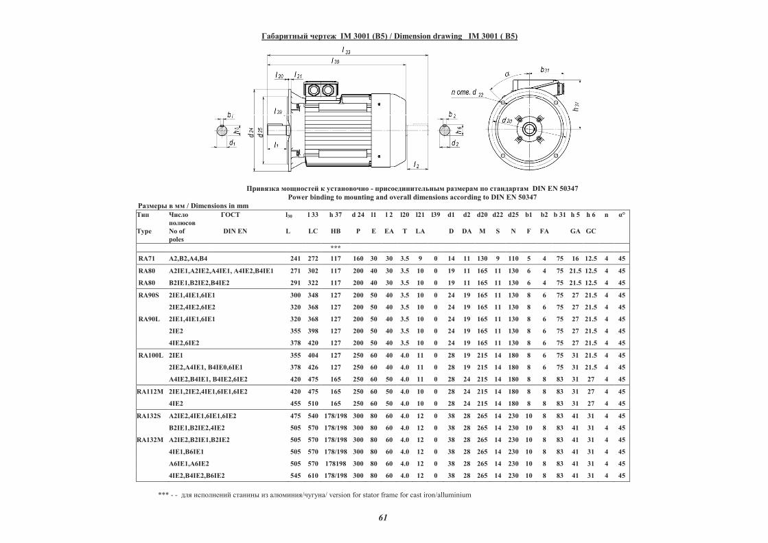
61
��������� ����� IM 3001 (B5) / Dimension drawing IM 3001 ( B5)
������� �������� � ���������� - ����������������� �������� �� ���������� DIN EN 50347
Power binding to mounting and overall dimensions according to DIN EN 50347
������� � �� / Dimensions in mm
���
Type
�����
�������
No of
poles
�� � l30
DIN EN L
l 33
LC
h 37
HB
d 24
P
l1
E
l 2
EA
l20
T
l21
LA
l39 d1
D
d2
DA
d20
M
d22
S
d25
N
b1
F
b2
FA
b 31 h 5
GA
h 6
GC
n !°
***
RA71 "2,#2,"4,#4 241 272 117 160 30 30 3.5 9 0 14 11 130 9 110 5 4 75 16 12.5 4 45
RA80 "2I$1,"2I$2,"4I$1, "4I$2,#4I$1 271 302 117 200 40 30 3.5 10 0 19 11 165 11 130 6 4 75 21.5 12.5 4 45
RA80 #2I$1,#2I$2,#4I$2 291 322 117 200 40 30 3.5 10 0 19 11 165 11 130 6 4 75 21.5 12.5 4 45
RA90S 2I$1,4I$1,6I$1 300 348 127 200 50 40 3.5 10 0 24 19 165 11 130 8 6 75 27 21.5 4 45
2I$2,4I$2,6I$2 320 368 127 200 50 40 3.5 10 0 24 19 165 11 130 8 6 75 27 21.5 4 45
RA90L 2I$1,4I$1,6I$1 320 368 127 200 50 40 3.5 10 0 24 19 165 11 130 8 6 75 27 21.5 4 45
2I$2 355 398 127 200 50 40 3.5 10 0 24 19 165 11 130 8 6 75 27 21.5 4 45
4I$2,6I$2 378 420 127 200 50 40 3.5 10 0 24 19 165 11 130 8 6 75 27 21.5 4 45
RA100L 2I$1 355 404 127 250 60 40 4.0 11 0 28 19 215 14 180 8 6 75 31 21.5 4 45
2I$2,A4I$1, B4I$0,6I$1 378 426 127 250 60 40 4.0 11 0 28 19 215 14 180 8 6 75 31 21.5 4 45
A4I$2,#4I$1, #4I$2,6I$2 420 475 165 250 60 50 4.0 11 0 28 24 215 14 180 8 8 83 31 27 4 45
RA112M 2I$1,2I$2,4I$1,6I$1,6I$2 420 475 165 250 60 50 4.0 10 0 28 24 215 14 180 8 8 83 31 27 4 45
4I$2 455 510 165 250 60 50 4.0 10 0 28 24 215 14 180 8 8 83 31 27 4 45
RA132S A2I$2,4I$1,6I$1,6I$2 475 540 178/198 300 80 60 4.0 12 0 38 28 265 14 230 10 8 83 41 31 4 45
#2I$1,#2I$2,4I$2 505 570 178/198 300 80 60 4.0 12 0 38 28 265 14 230 10 8 83 41 31 4 45
RA132M A2I$2,#2I$1,#2I$2 505 570 178/198 300 80 60 4.0 12 0 38 28 265 14 230 10 8 83 41 31 4 45
4I$1,#6I$1 505 570 178/198 300 80 60 4.0 12 0 38 28 265 14 230 10 8 83 41 31 4 45
"6I$1,"6I$2 505 570 178198 300 80 60 4.0 12 0 38 28 265 14 230 10 8 83 41 31 4 45
4I$2,#4I$2,#6I$2 545 610 178/198 300 80 60 4.0 12 0 38 28 265 14 230 10 8 83 41 31 4 45
*** - - ��� �������� ������ �� ��������/������/ version for stator frame for cast iron/alluminium
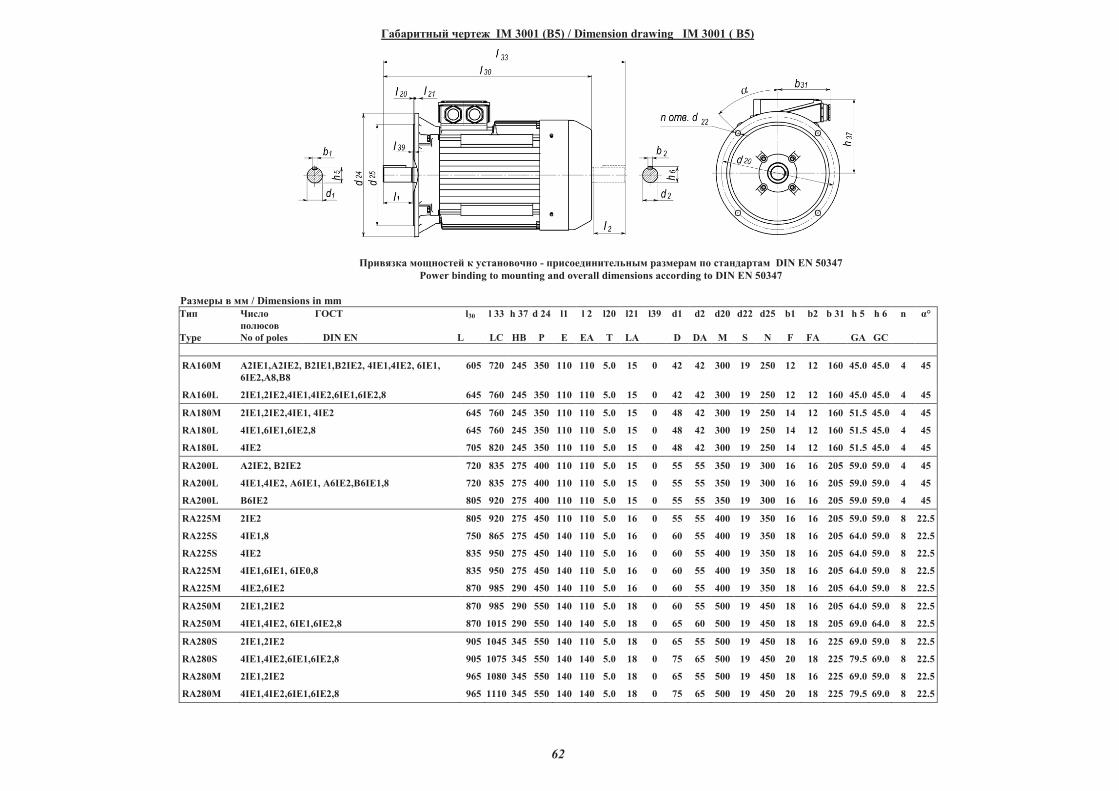
62
��������� ����� IM 3001 (B5) / Dimension drawing IM 3001 ( B5)
������� �������� � ���������� - ����������������� �������� �� ���������� DIN EN 50347
Power binding to mounting and overall dimensions according to DIN EN 50347
������� � �� / Dimensions in mm
���
Type
�����
�������
No of poles
�� � l30
DIN EN L
l 33
LC
h 37
HB
d 24
P
l1
E
l 2
EA
l20
T
l21
LA
l39 d1
D
d2
DA
d20
M
d22
S
d25
N
b1
F
b2
FA
b 31 h 5
GA
h 6
GC
n !°
RA160M "2IE1,"2IE2, #2IE1,#2IE2, 4IE1,4IE2, 6IE1,
6IE2,"8,#8
605 720 245 350 110 110 5.0 15 0 42 42 300 19 250 12 12 160 45.0 45.0 4 45
RA160L 2IE1,2IE2,4IE1,4IE2,6IE1,6IE2,8 645 760 245 350 110 110 5.0 15 0 42 42 300 19 250 12 12 160 45.0 45.0 4 45
RA180M 2IE1,2IE2,4IE1, 4IE2 645 760 245 350 110 110 5.0 15 0 48 42 300 19 250 14 12 160 51.5 45.0 4 45
RA180L 4IE1,6IE1,6IE2,8 645 760 245 350 110 110 5.0 15 0 48 42 300 19 250 14 12 160 51.5 45.0 4 45
RA180L 4IE2 705 820 245 350 110 110 5.0 15 0 48 42 300 19 250 14 12 160 51.5 45.0 4 45
RA200L "2IE2, #2IE2 720 835 275 400 110 110 5.0 15 0 55 55 350 19 300 16 16 205 59.0 59.0 4 45
RA200L 4IE1,4IE2, "6IE1, "6IE2,B6IE1,8 720 835 275 400 110 110 5.0 15 0 55 55 350 19 300 16 16 205 59.0 59.0 4 45
RA200L B6IE2 805 920 275 400 110 110 5.0 15 0 55 55 350 19 300 16 16 205 59.0 59.0 4 45
RA225M 2IE2 805 920 275 450 110 110 5.0 16 0 55 55 400 19 350 16 16 205 59.0 59.0 8 22.5
RA225S 4IE1,8 750 865 275 450 140 110 5.0 16 0 60 55 400 19 350 18 16 205 64.0 59.0 8 22.5
RA225S 4IE2 835 950 275 450 140 110 5.0 16 0 60 55 400 19 350 18 16 205 64.0 59.0 8 22.5
RA225M 4IE1,6IE1, 6IE0,8 835 950 275 450 140 110 5.0 16 0 60 55 400 19 350 18 16 205 64.0 59.0 8 22.5
RA225M 4IE2,6IE2 870 985 290 450 140 110 5.0 16 0 60 55 400 19 350 18 16 205 64.0 59.0 8 22.5
RA250M 2IE1,2IE2 870 985 290 550 140 110 5.0 18 0 60 55 500 19 450 18 16 205 64.0 59.0 8 22.5
RA250M 4IE1,4IE2, 6IE1,6IE2,8 870 1015 290 550 140 140 5.0 18 0 65 60 500 19 450 18 18 205 69.0 64.0 8 22.5
RA280S 2IE1,2IE2 905 1045 345 550 140 110 5.0 18 0 65 55 500 19 450 18 16 225 69.0 59.0 8 22.5
RA280S 4IE1,4IE2,6IE1,6IE2,8 905 1075 345 550 140 140 5.0 18 0 75 65 500 19 450 20 18 225 79.5 69.0 8 22.5
RA280M 2IE1,2IE2 965 1080 345 550 140 110 5.0 18 0 65 55 500 19 450 18 16 225 69.0 59.0 8 22.5
RA280M 4IE1,4IE2,6IE1,6IE2,8 965 1110 345 550 140 140 5.0 18 0 75 65 500 19 450 20 18 225 79.5 69.0 8 22.5
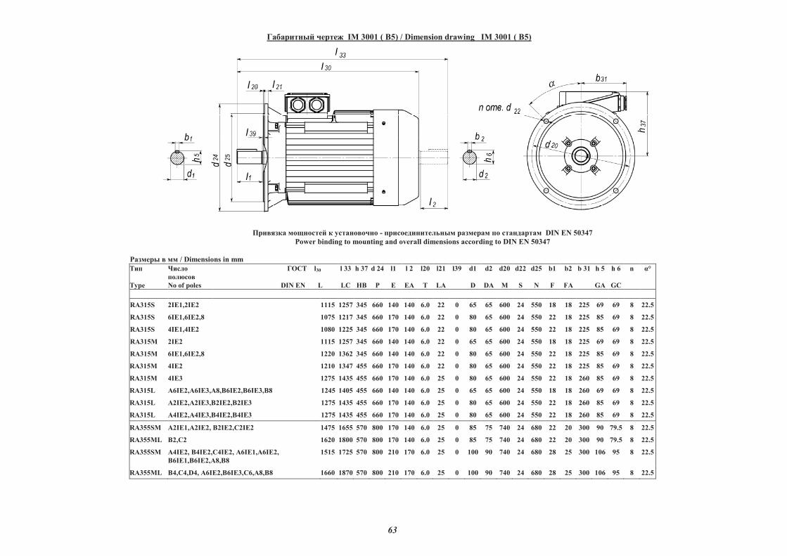
63
��������� ����� IM 3001 ( B5) / Dimension drawing IM 3001 ( B5)
������� �������� � ���������� - ����������������� �������� �� ���������� DIN EN 50347
Power binding to mounting and overall dimensions according to DIN EN 50347
������� � �� / Dimensions in mm
���
Type
�����
�������
No of poles
�� � l30
DIN EN L
l 33
LC
h 37
HB
d 24
P
l1
E
l 2
EA
l20
T
l21
LA
l39 d1
D
d2
DA
d20
M
d22
S
d25
N
b1
F
b2
FA
b 31 h 5
GA
h 6
GC
n !°
RA315S 2IE1,2IE2 1115 1257 345 660 140 140 6.0 22 0 65 65 600 24 550 18 18 225 69 69 8 22.5
RA315S 6IE1,6IE2,8 1075 1217 345 660 170 140 6.0 22 0 80 65 600 24 550 22 18 225 85 69 8 22.5
RA315S 4IE1,4IE2 1080 1225 345 660 170 140 6.0 22 0 80 65 600 24 550 22 18 225 85 69 8 22.5
RA315M 2IE2 1115 1257 345 660 140 140 6.0 22 0 65 65 600 24 550 18 18 225 69 69 8 22.5
RA315M 6IE1,6IE2,8 1220 1362 345 660 140 140 6.0 22 0 80 65 600 24 550 22 18 225 85 69 8 22.5
RA315M 4IE2 1210 1347 455 660 170 140 6.0 22 0 80 65 600 24 550 22 18 225 85 69 8 22.5
RA315M 4IE3 1275 1435 455 660 170 140 6.0 25 0 80 65 600 24 550 22 18 260 85 69 8 22.5
RA315L "6IE2,"6IE3,A8,#6IE2,#6IE3,#8 1245 1405 455 660 140 140 6.0 25 0 65 65 600 24 550 18 18 260 69 69 8 22.5
RA315L "2IE2,"2IE3,#2IE2,#2IE3 1275 1435 455 660 170 140 6.0 25 0 80 65 600 24 550 22 18 260 85 69 8 22.5
RA315L "4IE2,"4IE3,#4IE2,#4IE3 1275 1435 455 660 170 140 6.0 25 0 80 65 600 24 550 22 18 260 85 69 8 22.5
RA355SM "2IE1,"2IE2, #2IE2, 2IE2 1475 1655 570 800 170 140 6.0 25 0 85 75 740 24 680 22 20 300 90 79.5 8 22.5
RA355ML #2, 2 1620 1800 570 800 170 140 6.0 25 0 85 75 740 24 680 22 20 300 90 79.5 8 22.5
RA355SM "4IE2, #4IE2, 4IE2, "6IE1,"6IE2,
#6IE1,#6IE2,"8,#8
1515 1725 570 800 210 170 6.0 25 0 100 90 740 24 680 28 25 300 106 95 8 22.5
RA355ML #4, 4,D4, "6IE2,#6IE3, 6,"8,#8 1660 1870 570 800 210 170 6.0 25 0 100 90 740 24 680 28 25 300 106 95 8 22.5
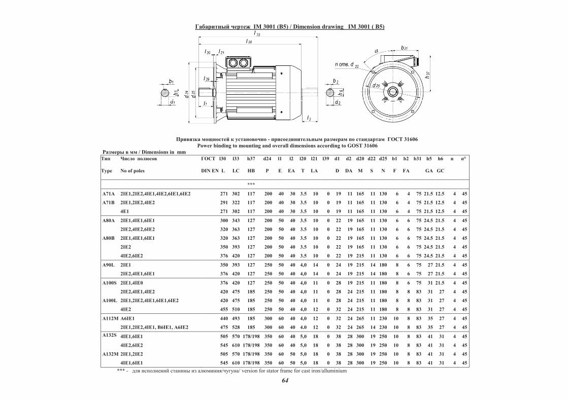
64
��������� ����� IM 3001 (B5) / Dimension drawing IM 3001 ( B5)
������� �������� � ���������� - ����������������� �������� �� ���������� ГОСТ 31606
Power binding to mounting and overall dimensions according to GOST 31606
Размеры в мм / Dimensions in mm
Тип
Type
Число полюсов
No of poles
ГОСТ l30
DIN EN L
l33
LC
h37
HB
d24
P
l1
E
l2
EA
l20
T
l21
LA
l39 d1
D
d2
DA
d20
M
d22
S
d25
N
b1
F
b2
FA
b31 h5
GA
h6
GC
n !°
***
A71A 2I"1,2I"2,4I"1,4I"2,6I"1,6I"2 271 302 117 200 40 30 3.5 10 0 19 11 165 11 130 6 4 75 21.5 12.5 4 45
A71B 2I"1,2I"2,4I"2 291 322 117 200 40 30 3.5 10 0 19 11 165 11 130 6 4 75 21.5 12.5 4 45
4"1 271 302 117 200 40 30 3.5 10 0 19 11 165 11 130 6 4 75 21.5 12.5 4 45
A80A
2I"1,4I"1,6I"1
2I"2,4I"2,6I"2
300
320
343
363
127
127
200
200
50
50
40
40
3.5
3.5
10
10
0
0
22
22
19
19
165
165
11
11
130
130
6
6
6
6
75
75
24.5
24.5
21.5
21.5
4
4
45
45
A80B
2I"1,4I"1,6I"1
2I"2
4I"2,6I"2
320
350
376
363
393
420
127
127
127
200
200
200
50
50
50
40
40
40
3.5
3.5
3.5
10
10
10
0
0
0
22
22
22
19
19
19
165
165
215
11
11
11
130
130
130
6
6
6
6
6
6
75
75
75
24.5
24.5
24.5
21.5
21.5
21.5
4
4
4
45
45
45
A90L 2I"1
2I"2,4I"1,6I"1
350
376
393
420
127
127
250
250
50
50
40
40
4,0
4,0
14
14
0
0
24
24
19
19
215
215
14
14
180
180
8
8
6
6
75
75
27
27
21.5
21.5
4
4
45
45
A100S
2I"1,4I"0
2I"2,4I"1,4I"2
376
420
420
475
127
185
250
250
50
50
40
40
4,0
4,0
11
11
0
0
28
28
19
24
215
215
11
11
180
180
8
8
6
8
75
83
31
31
21.5
27
4
4
45
45
A100L 2I"1,2I"2,4I"1,6I"1,6I"2
4I"2
420
455
475
510
185
185
250
250
50
50
40
40
4,0
4,0
11
12
0
0
28
32
24
24
215
215
11
11
180
180
8
8
8
8
83
83
31
31
27
27
4
4
45
45
A112M A6I"1 440 493 185 300 60 40 4,0 12 0 32 24 265 11 230 10 8 83 35 27 4 45
2I"1,2I"2,4I"1, #6I"1, $6I"2 475 528 185 300 60 40 4.0 12 0 32 24 265 14 230 10 8 83 35 27 4 45
A132S 4I"1,6I"1
4I"2,6I"2
505
545
570
610
178/198
178/198
350
350
60
60
40
40
5,0
5,0
18
18
0
0
38
38
28
28
300
300
19
19
250
250
10
10
8
8
83
83
41
41
31
31
4
4
45
45
A132M 2I"1,2I"2 505 570 178/198 350 60 50 5,0 18 0 38 28 300 19 250 10 8 83 41 31 4 45
4I"1,6I"1 545 610 178/198 350 60 50 5,0 18 0 38 28 300 19 250 10 8 83 41 31 4 45
*** - ��� �������� ������ �� ��������/������/ version for stator frame for cast iron/alluminium
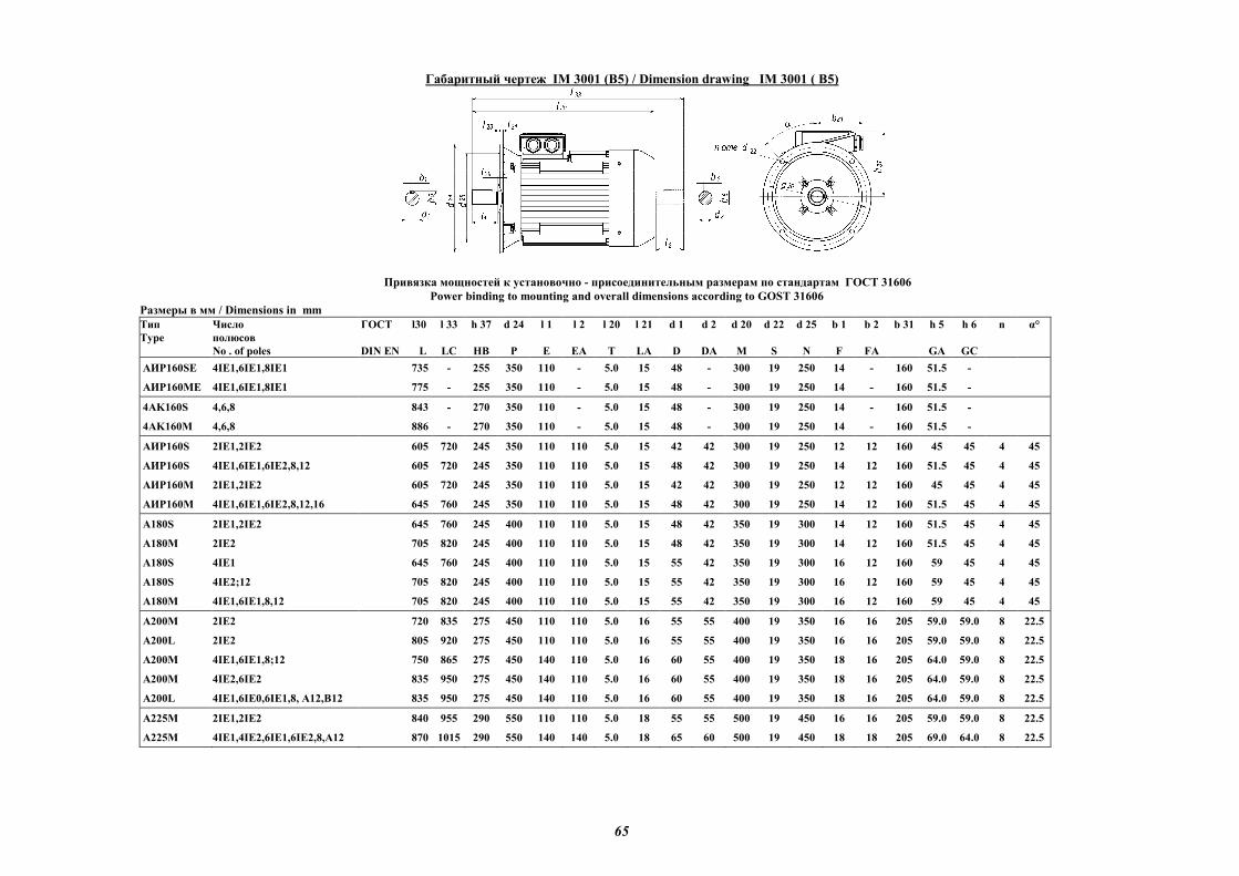
65
Габаритный чертеж IM 3001 (B5) / Dimension drawing IM 3001 ( B5)
Привязка мощностей к установочно - присоединительным размерам по стандартам ГОСТ 31606
Power binding to mounting and overall dimensions according to GOST 31606
Размеры в мм / Dimensions in mm
Тип
Type
Число
полюсов
No . of poles
ГОСТ l30
DIN EN L
l 33
LC
h 37
HB
d 24
P
l 1
E
l 2
EA
l 20
T
l 21
LA
d 1
D
d 2
DA
d 20
M
d 22
S
d 25
N
b 1
F
b 2
FA
b 31
h 5
GA
h 6
GC
n α°
АИР160SE 4IЕ1,6IЕ1,8IЕ1 735 - 255 350 110 - 5.0 15 48 - 300 19 250 14 - 160 51.5 -
АИР160ME 4IЕ1,6IЕ1,8IЕ1 775 - 255 350 110 - 5.0 15 48 - 300 19 250 14 - 160 51.5 -
4AK160S 4,6,8 843 - 270 350 110 - 5.0 15 48 - 300 19 250 14 - 160 51.5 -
4AK160M 4,6,8 886 - 270 350 110 - 5.0 15 48 - 300 19 250 14 - 160 51.5 -
АИР160S 2IЕ1,2IЕ2 605 720 245 350 110 110 5.0 15 42 42 300 19 250 12 12 160 45 45 4 45
АИР160S 4IE1,6IE1,6IE2,8,12 605 720 245 350 110 110 5.0 15 48 42 300 19 250 14 12 160 51.5 45 4 45
АИР160M 2IЕ1,2IЕ2 605 720 245 350 110 110 5.0 15 42 42 300 19 250 12 12 160 45 45 4 45
АИР160M 4IE1,6IE1,6IE2,8,12,16 645 760 245 350 110 110 5.0 15 48 42 300 19 250 14 12 160 51.5 45 4 45
А180S 2IЕ1,2IЕ2 645 760 245 400 110 110 5.0 15 48 42 350 19 300 14 12 160 51.5 45 4 45
А180M 2IЕ2 705 820 245 400 110 110 5.0 15 48 42 350 19 300 14 12 160 51.5 45 4 45
А180S 4IE1 645 760 245 400 110 110 5.0 15 55 42 350 19 300 16 12 160 59 45 4 45
А180S 4IE2;12 705 820 245 400 110 110 5.0 15 55 42 350 19 300 16 12 160 59 45 4 45
А180M 4IE1,6IE1,8,12 705 820 245 400 110 110 5.0 15 55 42 350 19 300 16 12 160 59 45 4 45
A200M 2IЕ2 720 835 275 450 110 110 5.0 16 55 55 400 19 350 16 16 205 59.0 59.0 8 22.5
A200L 2IЕ2 805 920 275 450 110 110 5.0 16 55 55 400 19 350 16 16 205 59.0 59.0 8 22.5
A200M 4IE1,6IE1,8;12 750 865 275 450 140 110 5.0 16 60 55 400 19 350 18 16 205 64.0 59.0 8 22.5
A200M 4IE2,6IE2 835 950 275 450 140 110 5.0 16 60 55 400 19 350 18 16 205 64.0 59.0 8 22.5
A200L 4IE1,6IЕ0,6IE1,8, А12,В12 835 950 275 450 140 110 5.0 16 60 55 400 19 350 18 16 205 64.0 59.0 8 22.5
A225M 2IE1,2IE2 840 955 290 550 110 110 5.0 18 55 55 500 19 450 16 16 205 59.0 59.0 8 22.5
A225M 4IE1,4IE2,6IE1,6IE2,8,A12 870 1015 290 550 140 140 5.0 18 65 60 500 19 450 18 18 205 69.0 64.0 8 22.5
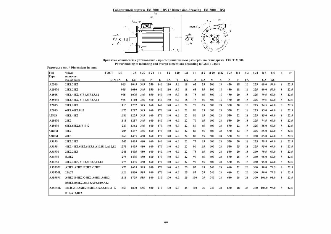
66
Габаритный чертеж IM 3001 ( B5 ) / Dimension drawing IM 3001 ( B5)
Привязка мощностей к установочно - присоединительным размерам по стандартам ГОСТ 31606
Power binding to mounting and overall dimensions according to GOST 31606
Размеры в мм. / Dimensions in mm.
Тип
Type
Число
полюсов
No. of poles
ГОСТ l30
DIN EN L
l 33
LC
h 37
HB
d 24
P
l 1
E
l 2
EA
l 20
T
l 21
LA
d 1
D
d 2
DA
d 20
M
d 22
S
d 25
N
b 1
F
b 2
FA
b 31 h 5
GA
h 6
GC
n α°
A250S 2IE1,2IE2 905 1045 345 550 140 110 5.0 18 65 55 500 19 450 18 16 225 69.0 59.0 8 22.5
A250M 2IE1,2IE2 965 1080 345 550 140 110 5.0 18 65 55 500 19 450 18 16 225 69.0 59.0 8 22.5
A250S 4IE1,4IE2, 6IE1,6IE2,8,12 905 1075 345 550 140 140 5.0 18 75 65 500 19 450 20 18 225 79.5 69.0 8 22.5
A250M 4IE1,4IE2, 6IE1,6IE2,8,12 965 1110 345 550 140 140 5.0 18 75 65 500 19 450 20 18 225 79.5 69.0 8 22.5
A280S 2IE1,2IE2 1115 1257 345 660 140 140 6.0 22 70 65 600 24 550 20 18 225 74.5 69.0 8 22.5
A280S 6IE1,6IE2,8,12 1075 1217 345 660 170 140 6.0 22 80 65 600 24 550 22 18 225 85.0 69.0 8 22.5
A280S 4IE1,4IE2 1080 1225 345 660 170 140 6.0 22 80 65 600 24 550 22 18 225 85.0 69.0 8 22.5
A280M 2IE2 1115 1257 345 660 140 140 6.0 22 70 65 600 24 550 20 18 225 74.5 69.0 8 22.5
A280M 6IE1,6IE2,8,"1012 1220 1362 345 660 170 140 6.0 22 80 65 600 24 550 22 18 225 85.0 69.0 8 22.5
A280M 4IE2 1205 1347 345 660 170 140 6.0 22 80 65 600 24 550 22 18 225 85.0 69.0 8 22.5
A280M 4IE3 1260 1435 480 660 170 140 6.0 22 80 65 600 24 550 22 18 260 85.0 69.0 8 22.5
A315S 2IE2,2IE3 1245 1405 480 660 140 140 6.0 22 75 65 600 24 550 20 18 225 79.5 69.0 8 22.5
A315S 4IE2,4IE3,6IE2,6IE3,8,#10,"10,#12,12 1275 1435 480 660 170 140 6.0 22 90 65 600 24 550 25 18 225 95.0 69.0 8 22.5
A315$ 2IE2,2IE3 1245 1405 480 660 140 140 6.0 22 75 65 600 24 550 20 18 260 79,5 69.0 8 22.5
A315M "2IE2 1275 1435 480 660 170 140 6.0 22 90 65 600 24 550 25 18 260 95.0 69.0 8 22.5
A315M 4IE2,4IE3, 6IE2,6IE3,8,10,12 1275 1435 480 660 170 140 6.0 22 90 65 600 24 550 25 18 260 95.0 69.0 8 22.5
A355SM #2IE1,#2IE2,"2IE2,�2IE2 1475 1635 585 800 170 140 6.0 25 85 65 740 24 680 22 20 300 90.0 79.5 8 22.5
A355ML 2",�2 1620 1800 585 800 170 140 6.0 25 85 75 740 24 680 22 20 300 90.0 79.5 8 22.5
A355SM #4IE2,"4IE2,�4IE2,#6IE1,#6IE2,
"6IE1,"6IE2,#8,"8,#10,"10,#12
1515 1725 585 800 210 170 6.0 25 100 75 740 24 680 28 25 300 106.0 95.0 8 22.5
A355ML 4",4�,4D,#6IE2,"6IE3,�6,8#,8", #10,
"10,#12,"12
1660 1870 585 800 210 170 6.0 25 100 75 740 24 680 28 25 300 106.0 95.0 8 22.5
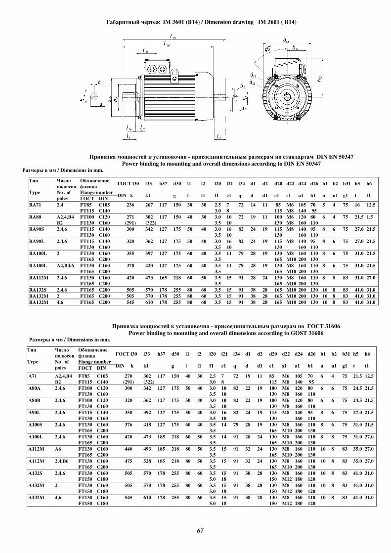
67
Габаритный чертеж IM 3601 (B14) / Dimension drawing IM 3601 ( B14)
Привязка мощностей к установочно - присоединительным размерам по стандартам DIN EN 50347
Power binding to mounting and overall dimensions according to DIN EN 50347 Размеры в мм / Dimensions in mm.
Тип
Type
Число
полюсов
No . of
poles
Обозначение
фланца
Flange number
ГОСТ l30
DIN k
l33
k1
h37
d30
g
l1
l
l2
l1
l20
f1
l21
c1
l34
q
d1
d
d2
d1
d20
e1
d22
s1
d24
a1
d26
b1
b1
u
b2
u1
b31
g1
h5
t
h6
t1 ГОСТ DIN
RA71 2,4 FT85 C105 236 267 117 150 30 30 2.5 7 72 14 11 85 M6 105 70 5 4 75 16 12.5
FT115 C140 3.0 8 115 M8 140 95
RA80 А2,4,В4 FT100 C120 271 302 117 150 40 30 3.0 10 72 19 11 100 M6 120 80 6 4 75 21.5 1.5
В2 FT130 C160 (291) (322) 3.5 10 130 M8 160 110
RA90S 2,4,6 FT115 C140 300 342 127 175 50 40 3.0 16 82 24 19 115 M8 140 95 8 6 75 27.0 21.5
FT130 C160 3.5 10 130 160 110
RA90L 2,4,6 FT115 C140 320 362 127 175 50 40 3.0 16 82 24 19 115 M8 140 95 8 6 75 27.0 21.5
FT130 C160 3.5 10 130 160 110
RA100L 2 FT130 C160 355 397 127 175 60 40 3.5 11 79 28 19 130 M8 160 110 8 6 75 31.0 21.5
FT165 C200 3.5 165 M10 200 130
RA100L A4,B4,6 FT130 C160 378 420 127 175 60 40 3.5 11 79 28 19 130 M8 160 110 8 6 75 31.0 21.5
FT165 C200 3.5 165 M10 200 130
RA112M 2,4,6 FT130 C160 420 473 165 218 60 50 3.5 15 91 28 24 130 M8 160 110 8 8 83 31.0 27.0
FT165 C200 3.5 165 M10 200 130
RA132S 2,4,6 FT165 C200 505 570 178 255 80 60 3.5 15 91 38 28 165 M10 200 130 10 8 83 41.0 31.0
RA132M 2 FT165 C200 505 570 178 255 80 60 3.5 15 91 38 28 165 M10 200 130 10 8 83 41.0 31.0
RA132M 4,6 FT165 C200 545 610 178 255 80 60 3.5 15 91 38 28 165 M10 200 130 10 8 83 41.0 31.0
Привязка мощностей к установочно - присоединительным размерам по ГОСТ 31606
Power binding to mounting and overall dimensions according to GOST 31606 Размеры в мм / Dimensions in mm.
Тип
Type
Число
полюсов
No . of
poles
Обозначение
фланца
Flange number
ГОСТ l30
DIN k
l33
k1
h37
d30
g
l1
l
l2
l1
l20
f1
l21
c1
l34
q
d1
d
d2
d1
d20
e1
d22
s1
d24
a1
d26
b1
b1
u
b2
u1
b31
g1
h5
t
h6
t1 ГОСТ DIN
A71 А2,4,В4 FT85 C105 270 302 117 150 40 30 2.5 7 72 19 11 85 M6 105 70 6 4 75 21.5 12.5
В2 FT115 C140 (291) (322) 3.0 8 115 M8 140 95
A80A 2,4,6 FT100 C120 300 342 127 175 50 40 3.0 10 82 22 19 100 M6 120 80 6 6 75 24.5 21.5
FT130 C160 3.5 10 130 M8 160 110
A80В 2,4,6 FT100 C120 320 362 127 175 50 40 3.0 10 82 22 19 100 M6 120 80 6 6 75 24.5 21.5
FT130 C160 3.5 10 130 M8 160 110
A90L 2,4,6 FT115 C140 350 392 127 175 50 40 3.0 16 82 24 19 115 M8 140 95 8 6 75 27.0 21.5
FT130 C160 3.5 10 130 160 110
A100S 2,4,6 FT130 C160 376 418 127 175 60 40 3.5 14 79 28 19 130 M8 160 110 8 6 75 31.0 21.5
FT165 C200 3.5 165 M10 200 130
A100L 2,4,6 FT130 C160 420 473 185 218 60 50 3.5 14 91 28 24 130 M8 160 110 8 8 75 31.0 27.0
FT165 C200 3.5 165 M10 200 130
A112М A6 FT130 C160 440 493 185 218 80 50 3.5 15 91 32 24 130 M8 160 110 10 8 83 35.0 27.0
FT165 C200 3.5 165 M10 200 130
A112М 2,4,В6 FT130 C160 475 528 185 218 80 50 3.5 15 91 32 24 130 M8 160 110 10 8 83 35.0 27.0
FT165 C200 3.5 165 M10 200 130
A132S 2,4,6 FT130 C160 505 570 178 255 80 60 3.5 15 91 38 28 130 M8 160 110 10 8 83 41.0 31.0
FT150 C180 5.0 18 150 M12 180 120
A132M 2 FT130 C160 505 570 178 255 80 60 3.5 15 91 38 28 130 M8 160 110 10 8 83 41.0 31.0
FT150 C180 5.0 18 150 M12 180 120
A132M 4,6 FT130 C160 545 610 178 255 80 60 3.5 15 91 38 28 130 M8 160 110 10 8 83 41.0 31.0
FT150 C180 5.0 18 150 M12 180 120
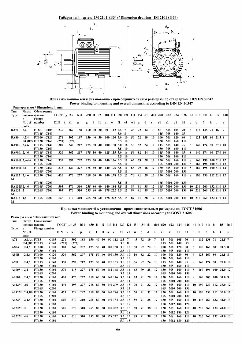
68
Габаритный чертеж IM 2101 (B34) / Dimension drawing IM 2101 ( B34)
Привязка мощностей к установочно - присоединительным размерам по стандартам DIN EN 50347
Power binding to mounting and overall dimensions according to DIN EN 50347 Размеры в мм / Dimensions in mm.
Тип
Type
Число
полюсо
в
No . of
poles
Обозначение
фланца
Flange
number
ГОСТ l 30
DIN k
l33
k1
h31
p
d30
g
l1
l
l2
l1
l10
a
l11
e
l20
f1
l21
c1
l31
w1
l34
q
d1
d
d10
s
d20
e1
d22
s1
d24
a1
d26
b1
b1
u
b10
b
b11
f
h
h
h5
t
h10
s
RA71 2,4 FT85 C105 236 267 188 150 30 30 90 112 2.5 7 45 72 14 7 85 M6 105 70 5 112 138 71 16 7
FT115 C140 3.0 8 115 M8 140 95
RA80 А2,4, FT100 C120 271 302 197 150 40 30 100 130 3.0 10 50 72 19 10 100 M6 120 80 6 125 155 80 21.5 8
В4 (В2) FT130 C160 (291) (322) 3.5 10 130 M8 160 110
RA90S 2,4,6 FT115 C140 300 342 217 175 50 40 100 130 3.0 16 56 82 24 10 115 M8 140 95 8 140 174 90 27.0 10
FT130 C160 3.5 10 130 M8 160 110
RA90L 2,4,6 FT115 C140 320 362 217 175 50 40 125 155 3.0 16 56 82 24 10 115 M8 140 95 8 140 174 90 27.0 10
FT130 C160 3.5 10 130 M8 160 110
RA100L 2,A4,6 FT130 C160 355 397 227 175 60 40 140 176 3.5 11 63 79 28 12 130 M8 160 110 8 160 196 100 31.0 12
FT165 C200 3.5 11 165 M10 200 130 8 160 196 100 31.0 12
RA100L B4 FT130 C160 378 420 227 175 60 40 140 176 3.5 11 63 79 28 12 130 M8 160 110 8 160 196 100 31.0 12
FT165 C200 3.5 11 165 M10 200 130
RA112
M
2,4,6 FT130 C160 420 473 277 218 60 50 140 178 3.5 15 70 91 28 12 130 M8 160 110 8 190 230 112 31.0 12
FT165 C200 3.5 15 165 M10 200 130
RA132S 2,4,6 FT165 C200 505 570 310 255 80 60 140 184 3.5 15 89 91 38 12 165 M10 200 130 10 216 260 132 41.0 13
RA132
M
2 FT165 C200 505 570 310 255 80 60 178 222 3.5 15 89 91 38 12 165 M10 200 130 10 216 260 132 41.0 13
RA132
M
4,6 FT165 C200 545 610 310 255 80 60 178 222 3.5 15 89 91 38 12 165 M10 200 130 10 216 260 132 41.0 13
Привязка мощностей к установочно - присоединительным размерам по ГОСТ 31606
Power binding to mounting and overall dimensions according to GOST 31606 Размеры в мм / Dimensions in mm.
Тип
Type
Число
полюсо
в
No . of
poles
Обозначение
фланца
Flange number
ГОСТ l 30
DIN k
l 33
k1
h31
p
d30
g
l1
l
l2
l1
l10
a
l11
e
l20
f1
l21
c1
l31
w1
l34
q
d1
d
d10
s
d20
e1
d22
s1
d24
a1
d26
b1
b1
u
b10
b
b11
f
h
h
h5
t
h10
s
A71 А2,A4, FT85 C105 271 302 188 150 40 30 90 112 2.5 7 45 72 19 7 85 M6 105 70 6 112 138 71 21.5 7
В4,(В2) FT115 C140 (291) (322) 3.0 8 115 M8 140 95
A80A 2,4,6 FT100 C120 300 342 207 175 50 40 100 130 3.0 10 50 82 22 10 100 M6 120 80 6 125 160 80 24.5 8
FT130 C160 3.5 10 130 M8 160 110
A80В 2,4,6 FT100 C120 320 362 207 175 50 40 100 130 3.0 10 50 82 22 10 100 M6 120 80 6 125 160 80 24.5 8
FT130 C160 3.5 10 130 M8 160 110
A90L 2,4,6 FT115 C140 350 392 217 175 50 40 125 155 3.0 16 56 82 24 10 115 M8 140 95 8 140 174 90 27.0 10
FT130 C160 3.5 10 130 M8 160 110
A100S 2,4 FT130 C160 376 418 227 175 60 40 112 148 3.5 14 63 79 28 12 130 M8 160 110 8 160 196 100 31.0 12
FT165 C200 3.5 14 165 M10 200 130
A100L 2,4,6 FT130 C160 420 473 277 218 60 50 140 176 3.5 14 63 91 28 12 130 M8 160 110 8 160 200 100 31.0 9
FT165 C200 3.5 14 165 M10 200 130
A112М A6 FT130 C160 440 493 297 218 80 50 140 209 3.5 15 70 91 32 12 130 M8 160 110 10 190 230 112 35.0 12
FT165 C200 3.5 15 165 M10 200 130
A112М 2,4,В6 FT130 C160 475 528 297 218 80 50 140 244 3.5 15 70 91 32 12 130 M8 160 110 10 190 230 112 35.0 12
FT165 C200 3.5 15 165 M10 200 130
A132S 2,4,6 FT130 C160 505 570 310 255 80 60 140 184 3.5 15 89 91 38 12 130 M8 160 110 10 216 260 132 41.0 13
FT150 C180 5.0 18 150 M12 180 120
A132M 2 FT130 C160 505 570 310 255 80 60 178 222 3.5 15 89 91 38 12 130 M8 160 110 10 216 260 132 41.0 13
FT150 C180 5.0 18 150 M12 180 120
A132M 4,6 FT130 C160 545 610 310 255 80 60 178 222 3.5 15 89 91 38 12 130 M8 160 110 10 216 260 132 41.0 13
FT150 C180 5.0 18 150 M12 180 120
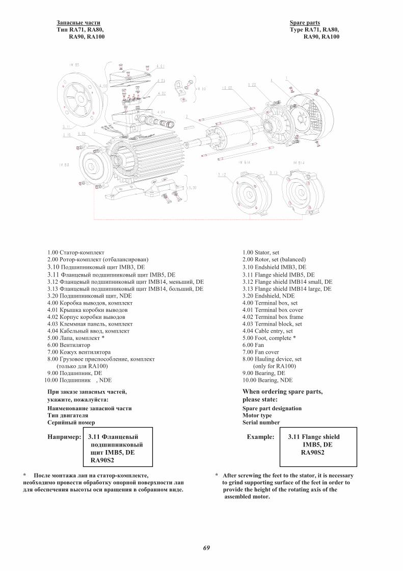
69
�������� ��� Spare parts
�� RA71, RA80, Type RA71, RA80,
RA90, RA100 RA90, RA100
1.00 ������-������ 1.00 Stator, set
2.00 �����-������ (����� ������ ) 2.00 Rotor, set (balanced)
3.10 ������ ������ ��� IMB3, DE 3.10 Endshield IMB3, DE
3.11 �� ���� ������ ������ ��� IMB5, DE 3.11 Flange shield IMB5, DE
3.12 �� ���� ������ ������ ��� IMB14, � ����, DE 3.12 Flange shield IMB14 small, DE
3.13 �� ���� ������ ������ ��� IMB14, ������, DE 3.13 Flange shield IMB14 large, DE
3.20 ������ ������ ���, NDE 3.20 Endshield, NDE
4.00 ������� �������, ������ 4.00 Terminal box, set
4.01 ������ ������� ������� 4.01 Terminal box cover
4.02 ������ ������� ������� 4.02 Terminal box frame
4.03 ��� �� �� �, ������ 4.03 Terminal block, set
4.04 ���� �� ����, ������ 4.04 Cable entry, set
5.00 ����, ������ * 5.00 Foot, complete *
6.00 � ������ 6.00 Fan
7.00 ���� � ������� 7.00 Fan cover
8.00 !��"��� ��������� �, ������ 8.00 Hauling device, set
(����� �� RA100) (only for RA100)
9.00 ������ ��, DE 9.00 Bearing, DE
10.00 ������ �� , NDE 10.00 Bearing, NDE
� ������ �������� �����, When ordering spare parts,
�����, ���������: please state:
���������� �������� ��� Spare part designation
�� ������� Motor type
�� ���� ���� Serial number
��� �� : 3.11 ��������� Example: 3.11 Flange shield
����������� IMB5, DE
IMB5, DE RA90S2
RA90S2
* ����� ������ ��� �� ��� -��������, * After screwing the feet to the stator, it is necessary
���!����� � ���� �! �!��� ��� ��� ���� ���� ��� to grind supporting surface of the feet in order to
��� �!�������� ����� �� � � ��� � ��! ����� ���. provide the height of the rotating axis of the
assembled motor.
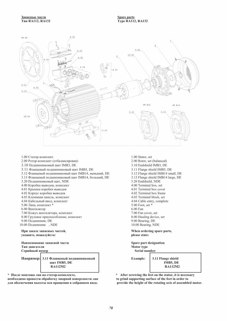
70
�������� ��� Spare parts
�� RA112, RA132 Type RA112, RA132
1.00 ������-������ 1.00 Stator, set
2.00 �����-������ (����� ������ ) 2.00 Rotor, set (balanced)
3.10 ������ ������ ��� IMB3, DE 3.10 Endshield IMB3, DE
3.11 �� ���� ������ ������ ��� IMB5, DE 3.11 Flange shield IMB5, DE
3.12 �� ���� ������ ������ ��� IMB14, � ����, DE 3.12 Flange shield IMB14 small, DE
3.13 �� ���� ������ ������ ��� IMB14, ������, DE 3.13 Flange shield IMB14 large, DE
3.20 ������ ������ ���, NDE 3.20 Endshield, NDE
4.00 ������� �������, ������ 4.00 Terminal box, set
4.01 ������ ������� ������� 4.01 Terminal box cover
4.02 ������ ������� ������� 4.02 Terminal box frame
4.03 ��� �� �� �, ������ 4.03 Terminal block, set
4.04 ���� �� ����, ������ 4.04 Cable entry, complete
5.00 ����, ������ * 5.00 Foot, set *
6.00 � ������ 6.00 Fan
7.00 ���� � �������, ������ 7.00 Fan cover, set
8.00 !��"��� ��������� �, ������ 8.00 Hauling device, set
9.00 ������ ��, DE 9.00 Bearing, DE
10.00 ������ �� , NDE 10.00 Bearing, NDE
� ������ �������� �����, When ordering spare parts,
�����, ���������: please state:
���������� �������� ��� Spare part designation
�� ������� Motor type
�� ���� ���� Serial number
��� �� : 3.11 ��������� ����������� Example: 3.11 Flange shield
IMB5, DE IMB5, DE
RA112M2 RA112M2
* ����� ������ ��� �� ��� -��������, * After screwing the feet on the stator, it is necessary
���!����� � ���� �! �!��� ��� ��� ���� ���� ��� to grind supporting surface of the feet in order to
��� �!�������� ����� �� � � ��� � ��! ����� ���. provide the height of the rotating axis of assembled motor.
IM B14 IM B14
1
2
3.10
3.20
6
7
IM B3
IM B5
4.00
5.00
8.00
4.04
4.03
4.01
4.02
3.11
3.12 3.13
9.00
10.00
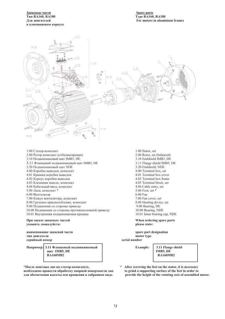
71
�������� ��� Spare parts
�� RA160, RA180 Type RA160, RA180
� � ����� �� For motors in aluminium frames
� � ������� �������
1.00 ������-������ 1.00 Stator, set
2.00 �����-������ (����� ������ ) 2.00 Rotor, set (balanced)
3.10 ������ ������ ��� IMB3, DE 3.10 Endshield IMB3, DE
3.11 �� ���� ������ ������ ��� IMB5, DE 3.11 Flange shield IMB5, DE
3.20 ������ ������ ��� NDE 3.20 Endshield, NDE
4.00 ������� �������, ������ 4.00 Terminal box, set
4.01 ������ ������� ������� 4.01 Terminal box cover
4.02 ������ ������� ������� 4.02 Terminal box frame
4.03 ��� �� �� �, ������ 4.03 Terminal block, set
4.04 ���� �� ����, ������ 4.04 Cable entry, set
5.00 ����, ������ * 5.00 Foot, set *
6.00 � ������ 6.00 Fan
7.00 ���� � �������, ������ 7.00 Fan cover, set
8.00 !��"��� ��������� �, ������ 8.00 Hauling device, set
9.00 ������ �� �� ����� � ������� 9.00 Bearing, DE
10.00 ������ �� �� ����� � ����������� �� ������� 10.00 Bearing, NDE
10.01 � ��� �� ������ ������ ������ 10.01 Inner bearing cap, NDE
�� ������ �������� ����� When ordering spare parts
�����, ���� ����: please state:
���������� �������� ��� spare part designation
� ����� � motor type
������� ����� serial number
�������: 3.11 � ������� ��� ������� Example: 3.11 Flange shield
! IMB5, DE IMB5, DE
RA160MB2 RA160MB2
*��� � ������ �� �� ����-���� ���, * After screwing the feet on the stator, it is necessary
���"����� ������ �"��"��� ������� ��������� �� to grind a supporting surface of the feet in order to
� � �"�������� ����� �� ���!��� � ��"������ ���. provide the height of the rotating axis of assembled motor.