El diseño de uniones metálicas reinventado -...
65
El diseño de uniones metálicas – reinventado Juraj Sabatka, CSO&CFO
Transcript of El diseño de uniones metálicas reinventado -...

El diseño de uniones metálicas –reinventado
Juraj Sabatka, CSO&CFO

3
Este es David, un ingeniero estructural…
4
¿Puede calcular estas uniones, David?

¿Cuál es el problema?
Unión diseñada, de forma laboriosa. ¿Qué pasa si la unión cambia un poco? Hay que empezar desde cero…
5
David no ha encontrado un
ejemplo verificado como este
¿Puede entrarlo en un modelo de EF
avanzado?
¿Puede verificar a partir del modelo
EF según una norma?
No
La unión no puede diseñarse
Se necesita una nueva aproximación
Sí
Sí
No

6
David conoce IDEA RS
IDEA RS con base en Brno,
República Checa, desde 2009
22 personas
Producto = IDEA StatiCa Acero,
Hormigón y Pretensado
Escritorio: 800 licencias, 30
países
Cloud (beta): 3000 usuarios,
mundial
IDEA StatiCa
Connection
IDEA StatiCa Steel
FEA links
CAD links
Trayectoria de nuestros líderes
Liderando equipos de desarrollo desde 1986
La primera solución de software en Europa
para análisis estructural basada en Windows
en los 90
Director de desarrollo en Nemetschek SCIA
Programas: ESA Prima Win, SCIA Engineer

Socios

8
IDEA RS = Autodesk AEC Solution Associate
Advance Steel, Robot Structural Analysis, Revit, Tekla
Socios

Simplifica y automatiza
9
Modelo ideal plástico del material (Línea verde)
Crea el modelo de análisis automáticamente
Realiza todas verificaciones a la vez
Proporciona resultados claros de pasa/no pasa
Realiza el proceso entero en minutos
Cualquier tipología, cualquier carga, en minutos

Diseñado por IDEA StatiCa Connection
10
Deformación plástica equivalente
12%
4,5%
0,5%
Cartela o
rigidizador
añadido
Diseño con IDEA StatiCa Connection
11
Basado en un Nuevo método – Modelo de Componentes Basado en
Elementos Finitos (CBFEM)
Sinergia del Método de los Componentes Estándar y el Análisis de Elementos
Finitos
Solución única patentada

Verificación – Tipologías simples
12
CBFEM da resultados de acuerdo al AISC/Eurocódigo
Unión con placa y tapa para perfil CHSUnión a cortante con placa simple

Verificación – Tipologías simples
13
CBFEM da resultados de acuerdo al AISC/Eurocódigo
Tubo – Cartela en arriostramiento Empalme por alas de viga en doble T
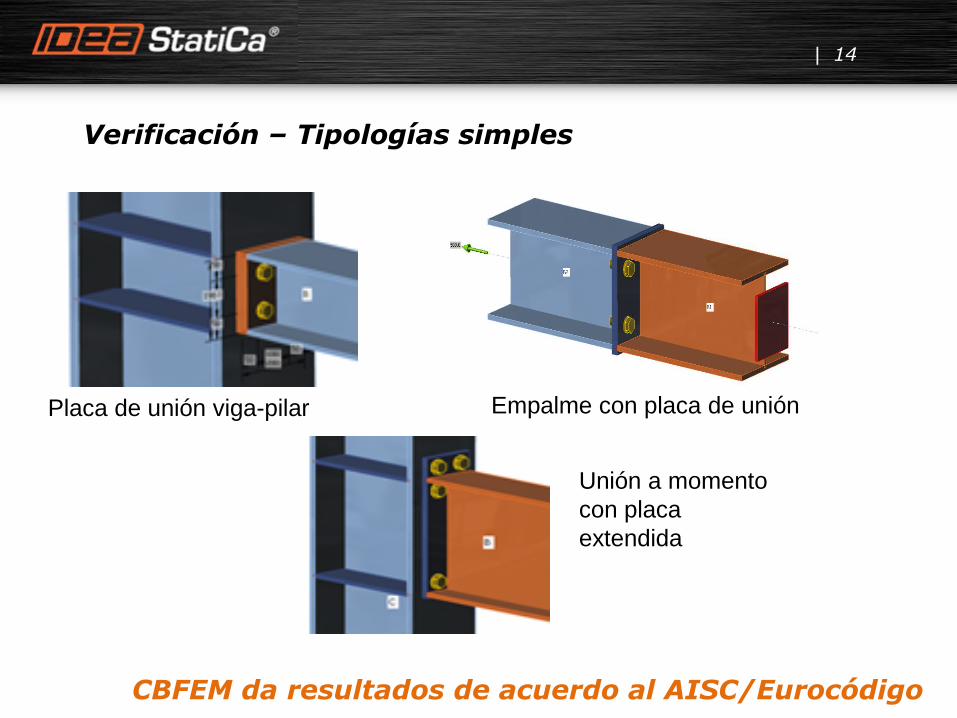
Verificación – Tipologías simples
14
Placa de unión viga-pilar
Unión a momento
con placa
extendida
Empalme con placa de unión
CBFEM da resultados de acuerdo al AISC/Eurocódigo

Verificación – Tipologías complejas
Modelos únicos creados y
comparados con varios softwares
Ensayos en laboratorio
Todos los estudios publicados
Dos equipos universitarios
invirtieron 3 años en ello

Cooperación con universidades = Solución verificada
16

¿Es realmente tan rápido?
17
… en 10 minutos

18
Carga = 25%
Eps = 0,1%
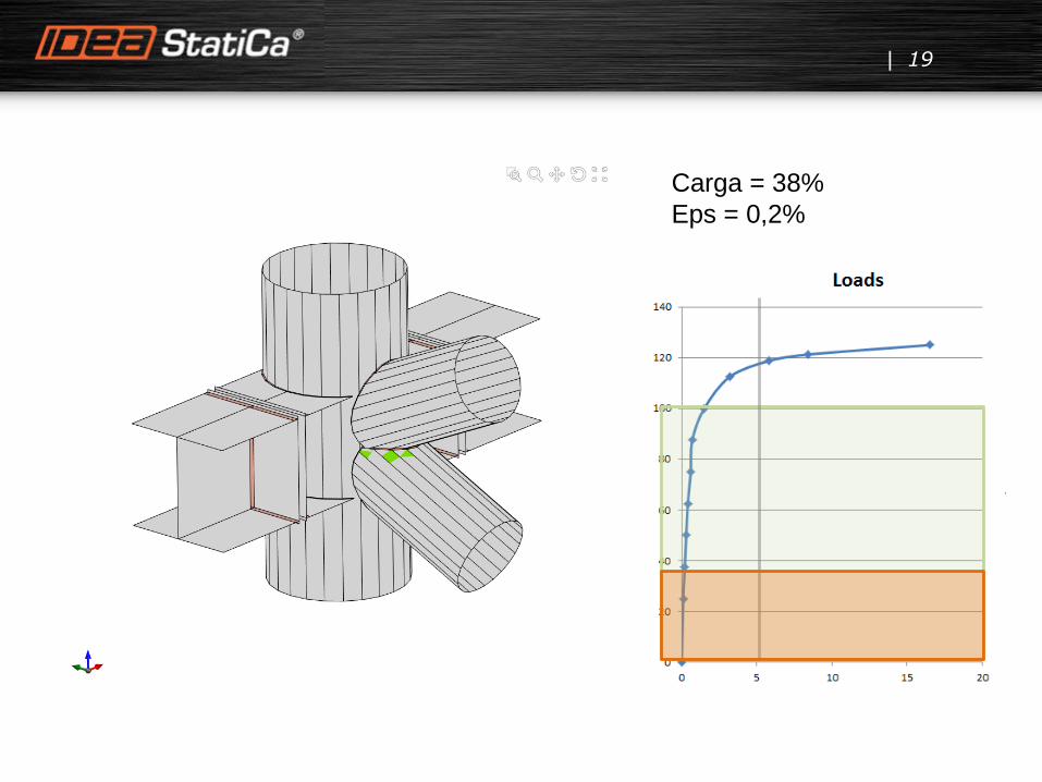
19
Carga = 38%
Eps = 0,2%
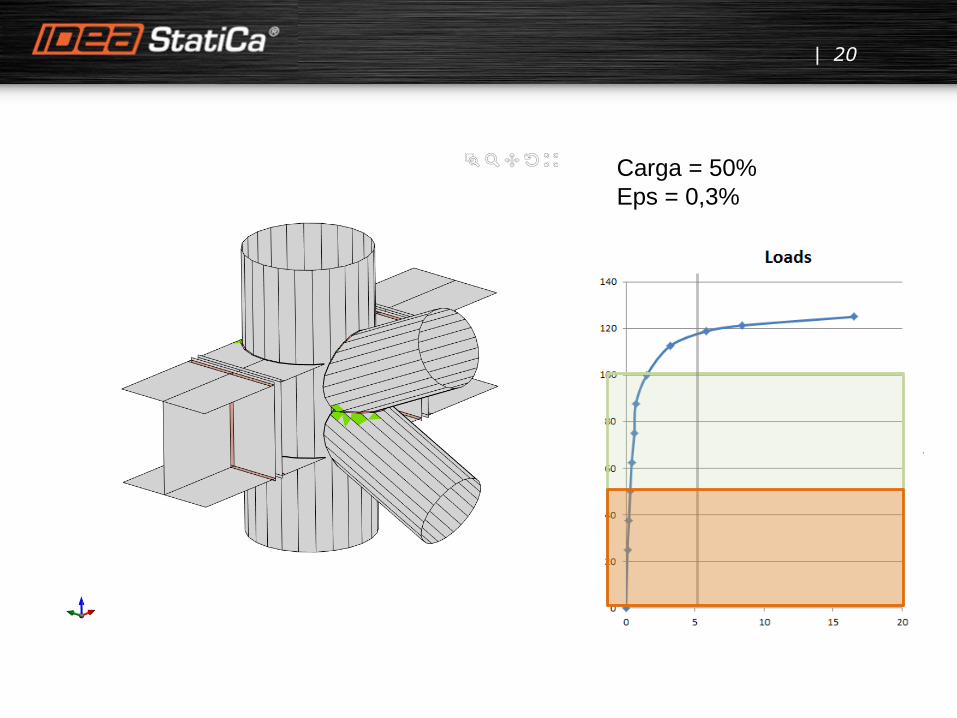
20
Carga = 50%
Eps = 0,3%

21
Carga = 63%
Eps = 0,4%
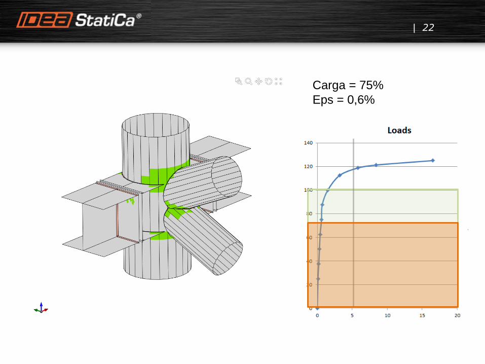
22
Carga = 75%
Eps = 0,6%
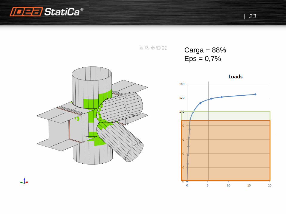
23
Carga = 88%
Eps = 0,7%

24
Carga = 100%
Eps = 1,5%

25
Carga = 113%
Eps = 3,2%

26
Carga = 119%
Eps = 5,8%

27
Carga = 121%
Eps = 8,4%

28
Carga = 125%
Eps = 16,5%

Modelo Método de los Componentes Basado en Elemento Finito (CBFEM)
29
El punto débil del Método de los Componentes / Guías de diseño es
que la tipología de uniones es limitada
Usamos elementos finitos para conocer las tensiones y las deformaciones
Aplicamos las verificaciones de los códigos sobre ello
Cualquier tipología cualquier carga, en cuestión de minutos

Características innovadoras
30
Placas malladas de forma independiente, tensiones por contacto

Características innovadoras
31
Tornillos a cortante, tornillos a tracción, Placas en contacto

Características innovadoras
32
Operaciones de detallado

Interfaz BIM – programas de análisis por EF
33
Robot Structural Analysis, SCIA Engineer, AxisVM, RFEM, MIDAS Civil/Gen
SAP 2000 versión 7 (Junio 2016)

Interfaz BIM – programas de diseño BIM
34
Enlaces ya desarrollados para Advance Steel y Tekla Structures
400 licencias de acero en 25 países
35

Ejemplos de nuestros clientes – placa transversal en el eje débil de la columna
36
Aumentar la placa Aumentar grosor de alma Rigidizadores
Colapso del alma de la
columna.
Deformación equivalente
es del 15%.

Ejemplos de nuestros clientes – arriostramiento en cruz de diagonales
37
Deformación de CHS. La rigidez perpendicular de CHS es más débil.
Todos los CHS soldados a una placa. La rigidez es 10 veces más alta.
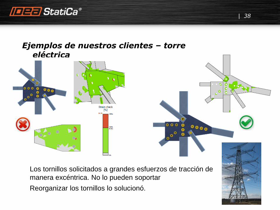
Ejemplos de nuestros clientes – torre eléctrica
38
Los tornillos solicitados a grandes esfuerzos de tracción de
manera excéntrica. No lo pueden soportar
Reorganizar los tornillos lo solucionó.

Ejemplos de nuestros clientes – pasarela puente
39
La unión no se podía diseñar con los
requerimientos prescritos y los modelos del EC3,
era necesario adoptar una aproximación más
genérica.

40
Diseño de uniones de acero - IDEA StatiCa Connection
Cálculos manuales
Hojas de cálculo en Excel
Modelos avanzados científicos
Cualquier tipología, cualquier carga,
en minutos
Verificaciones pasa/no pasa EN/AISC
Standalone, vínculos a CAD/FEA
Resultados verificados por universidades
Tecnología única patentada

41
¿Las recuerdan?

42
David puede calcular lo que antes solo estimaba

Steel connection design –selected issues
Lubomir Sabatka, CEO

44
This is David, an experienced user of IDEA StatiCa Connection…

45
… but he still has questions.

Topics and issues
46
• CBFEM model – plates, stress, plastic hinge
• CBFEM model – how to apply loads
• Bolts – block tearing, bearing resistance, distance between bolts, tension forces
• Anchors checks
• Buckling – limits
• Stiffness
Any topology, any loading, in minutes

CBFEM model – plates, stress
47
The resulting equivalent stress (HMH,
von Mieses) and plastic strain are
calculated on plates. The stress check
cannot be performed, because the stress
reaches the yield strength only. Thus the
check of equivalent plastic strain is
performed. The limit value 5% is
suggested in Eurocode (EN1993-1-5
app. C par. C8 note 1), this value can be
modified in project settings.
Plate element is divided to 7 layers and
elastic/plastic behavior is investigated in
each of them. Program shows the worst
result of stress or strain from all of them.

48
CBFEM model – plastic hinge

CBFEM model – how to apply loads
49
1. IDEA StatiCa Connection does not calculate the whole structure – there is a
lot of appropriate tools to do that (Robot, SAP2000, Consteel etc). We are the
next step in the design process, making more precise model of a part of that
3D structure (frame). All internal (dead weight) and external (wind, snow,
traffic) loads are put on the 3D structure, not on the model of connection.
2. IDEA StatiCa Connection takes out one node of analyzed 3D frame, adds end
stubs of connected members and construct their connection like in reality.
IDEA StatiCa Connection resolves only the node and it close neighborhood..
3. IDEA StatiCa Connection takes end internal forces of all connected members
and transfer them as loads on ends of related stubs. Forces are extrapolated
from end of stub closer to node to the farther end of stub.
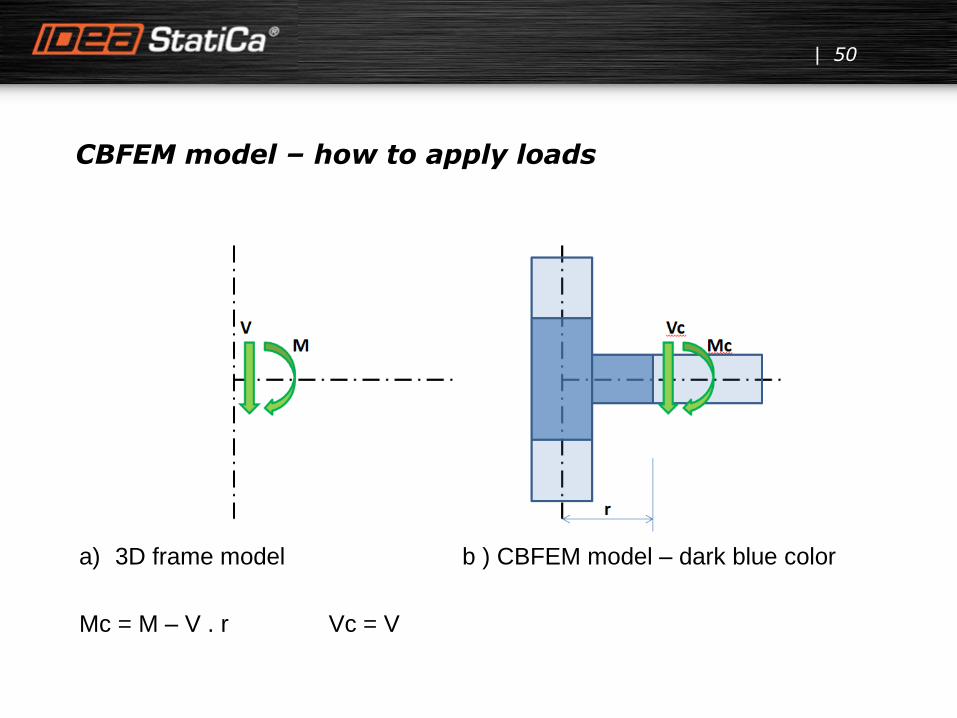
CBFEM model – how to apply loads
50
a) 3D frame model b ) CBFEM model – dark blue color
Mc = M – V . r Vc = V

CBFEM model – how to apply loads
51
Real forces in connection are used.
Problem appears when both models are not
coincident. Then position of internal forces has
to be shifted.
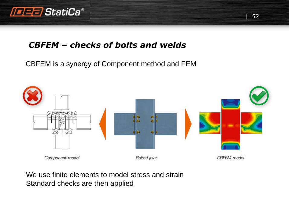
CBFEM – checks of bolts and welds
52
CBFEM is a synergy of Component method and FEM
We use finite elements to model stress and strain
Standard checks are then applied

Cooperation with universities = Verified solution
53

Check of bolts - block tearing
54
IDEA Connection covers all such effect directly in FE model of plates
Vy shear – strain Vy and N – strain check

Check of bolts - block tearing
55
Vy shear Vy and N

Check of bolts – bearing check with alpha b
56
IDEA Connection takes into account the effect of more bolts in one line in
direction of load force.

Check of bolts – bearing check with alpha b
57
Shear force Tensile force

Fillet welds – evaluation of stress
58
The stress in the throat section of fillet weld is determined according to art.
4.5.3.
Program calculates precise values in weld link. User can decide how to
evaluate the value for the check. There are 3 options:
Maximal stress Average stress Linear interpolation

Fillet welds – evaluation of stress
59
Method 1 can be too conservative in many cases. Method 2 simulates the
situation when the whole weld can be plastic. In majority of cases it is close
to the reality, but for instance for long welds this method is not appropriate.
Similar situation is with method 3.
New model with full plastic behavior of welds is under the development. It
will replace all 3 current method. The release is expected in version 7.1.

Anchoring – contact stress
60
Effective area is calculated according to the real course of contact stress and
assumptions defined in Eurocode. Graphical representation shows the way
of checking. Calculated effective area is marked as green. Final effective
area for contact stress check is highlighted as shaded.

Stiffness of connection
61
Stiffness of one member connection to the whole joint can be analyzed.
2 models are created and compared – CBFEM and 1D member model.
The difference between them is expected as a flexible hinge stiffness.

Stiffness of connection
62
Level of design load
Limit value of capacity of connection for 5% equivalent strain
Limit value of capacity of connected member (useful also for seismic design)
2/3 of limit capacity for calculation of initial stiffness
Value of initial stiffness
Limits for the classification ofconnection – rigid and pinned
.

Local buckling
63
The advantage of the procedure is the advanced FEM analysis of the whole joint, which can be applied to general geometry. It is included in valid Eurocode standards.
The limit slenderness λp is provided in Annex B of EN 1993-1-5 and sets all cases which must be assessed according to previous procedure. The resistance is limited by buckling for plate slenderness higher than 0.7. With the decreasing slenderness is the resistance governed by plastic strain. The limit critical buckling factor for plate slenderness equal to 0.7 and buckling resistance can be derived from it.
0.0
0.2
0.4
0.6
0.8
1.0
1.2
0 1 2 3 4
Buck
lin
g r
edu
ctio
n f
acto
r ρ
[-]
Plate slenderness λp [-]
Annex B
Buckling reduction factor ρ according to EN 1993-1-5 Annex B
It is recommended to check the buckling resistance for critical buckling resistance smaller than 3.

Local buckling
64
It is recommended to check the buckling resistance for critical buckling resistance smaller than 3.

BIM interface – CAD programs
65
Links already developed for Advance Steel and Tekla Structures

66
David is now happy.