EL 2835 67-11S-C80600H-AM - Everlight ElectronicsDATASHEET 67-11S-C80600H-AM Copyright © 2017,...
26
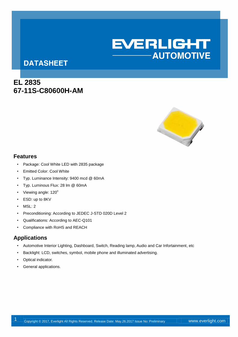
1 Copyright © 2017, Everlight All Rights Reserved. Release Date: May.26.2017 Issue No: Preliminary www.everlight.com EL 2835 67-11S-C80600H-AM Features • Package: Cool White LED with 2835 package • Emitted Color: Cool White • Typ. Luminance Intensity: 9400 mcd @ 60mA • Typ. Luminous Flux: 28 lm @ 60mA • Viewing angle: 120 o • ESD: up to 8KV • MSL: 2 • Preconditioning: According to JEDEC J-STD 020D Level 2 • Qualifications: According to AEC-Q101 • Compliance with RoHS and REACH Applications • Automotive Interior Lighting, Dashboard, Switch, Reading lamp, Audio and Car Infortainment, etc • Backlight: LCD, switches, symbol, mobile phone and illuminated advertising. • Optical indicator. • General applications.
Transcript of EL 2835 67-11S-C80600H-AM - Everlight ElectronicsDATASHEET 67-11S-C80600H-AM Copyright © 2017,...
1 Copyright © 2017, Everlight All Rights Reserved. Release Date: May.26.2017 Issue No: Preliminary www.everlight.com
EL 2835 67-11S-C80600H-AM
Features
• Package: Cool White LED with 2835 package
• Emitted Color: Cool White
• Typ. Luminance Intensity: 9400 mcd @ 60mA
• Typ. Luminous Flux: 28 lm @ 60mA
• Viewing angle: 120o
• ESD: up to 8KV
• MSL: 2
• Preconditioning: According to JEDEC J-STD 020D Level 2
• Qualifications: According to AEC-Q101
• Compliance with RoHS and REACH
Applications
• Automotive Interior Lighting, Dashboard, Switch, Reading lamp, Audio and Car Infortainment, etc
• Backlight: LCD, switches, symbol, mobile phone and illuminated advertising.
• Optical indicator.
• General applications.
DATASHEET 67-11S-C80600H-AM
2 Copyright © 2017, Everlight All Rights Reserved. Release Date: May.26.2017 Issue No: Preliminary www.everlight.com
Contents Characteristics .............................................................................................................................. 3
Absolute Maximum Ratings ............................................................................................ 4
Characteristics Graph ........................................................................................................... 5
Binning Information ............................................................................................................... 10
Part Number ................................................................................................................................... 19
Ordering Information ............................................................................................................ 20
Mechanical Dimension ........................................................................................................ 21
Recommended Soldering Pad .................................................................................... 22
Reflow Soldering Profile ................................................................................................... 22
Packaging Information ........................................................................................................ 23
Precaution for Use................................................................................................................... 25
DATASHEET 67-11S-C80600H-AM
3 Copyright © 2017, Everlight All Rights Reserved. Release Date: May.26.2017 Issue No: Preliminary www.everlight.com
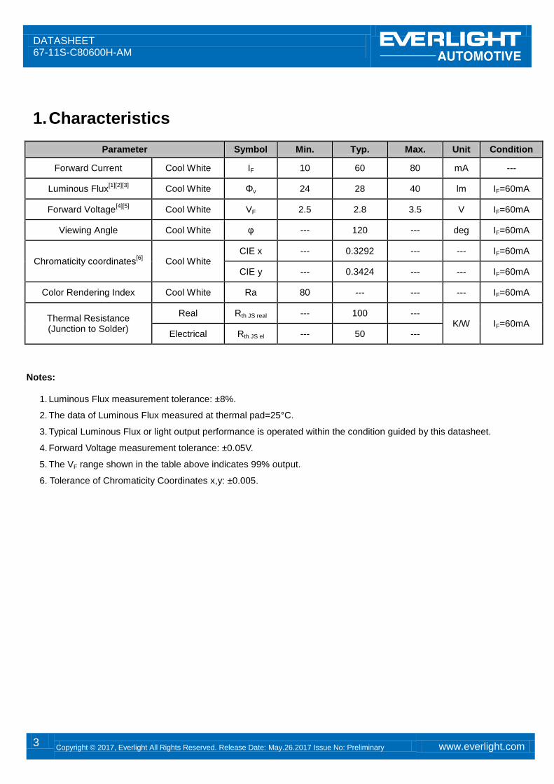
1. Characteristics
Parameter Symbol Min. Typ. Max. Unit Condition
Forward Current Cool White IF 10 60 80 mA ---
Luminous Flux[1][2][3] Cool White Φv 24 28 40 lm IF=60mA
Forward Voltage[4][5] Cool White VF 2.5 2.8 3.5 V IF=60mA
Viewing Angle Cool White φ --- 120 --- deg IF=60mA
Chromaticity coordinates[6] Cool White
CIE x --- 0.3292 --- --- IF=60mA
CIE y --- 0.3424 --- --- IF=60mA
Color Rendering Index Cool White Ra 80 --- --- --- IF=60mA
Thermal Resistance (Junction to Solder)
Real Rth JS real --- 100 --- K/W IF=60mA
Electrical Rth JS el --- 50 ---
Notes:
1. Luminous Flux measurement tolerance: ±8%.
2. The data of Luminous Flux measured at thermal pad=25°C.
3. Typical Luminous Flux or light output performance is operated within the condition guided by this datasheet.
4. Forward Voltage measurement tolerance: ±0.05V.
5. The VF range shown in the table above indicates 99% output.
6. Tolerance of Chromaticity Coordinates x,y: ±0.005.
DATASHEET 67-11S-C80600H-AM
4 Copyright © 2017, Everlight All Rights Reserved. Release Date: May.26.2017 Issue No: Preliminary www.everlight.com
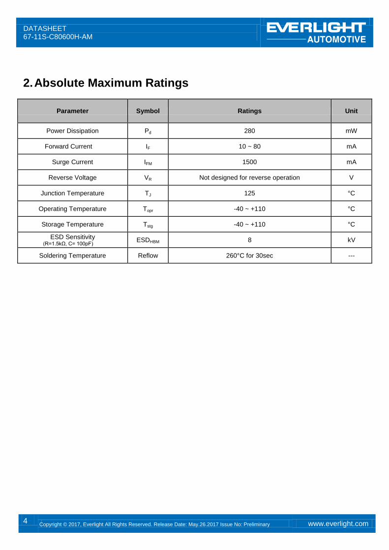
2. Absolute Maximum Ratings
Parameter Symbol Ratings Unit
Power Dissipation Pd 280 mW
Forward Current IF 10 ~ 80 mA
Surge Current IFM 1500 mA
Reverse Voltage VR Not designed for reverse operation V
Junction Temperature TJ 125 °C
Operating Temperature Topr -40 ~ +110 °C
Storage Temperature Tstg -40 ~ +110 °C
ESD Sensitivity (R=1.5kΩ, C= 100pF)
ESDHBM 8 kV
Soldering Temperature Reflow 260°C for 30sec ---
DATASHEET 67-11S-C80600H-AM
5 Copyright © 2017, Everlight All Rights Reserved. Release Date: May.26.2017 Issue No: Preliminary www.everlight.com
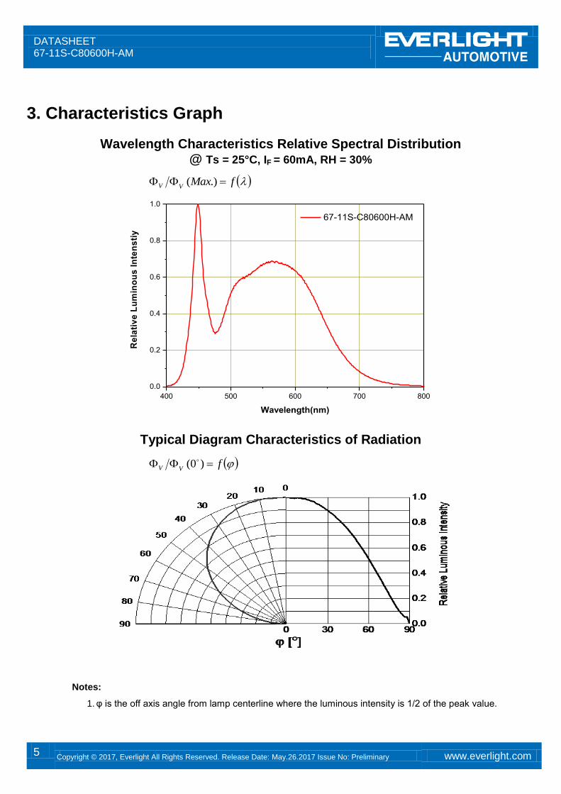
3. Characteristics Graph
Wavelength Characteristics Relative Spectral Distribution @ Ts = 25°C, IF = 60mA, RH = 30%
400 500 600 700 800
0.0
0.2
0.4
0.6
0.8
1.0
67-11S-C80600H-AM
Re
lati
ve
Lu
min
ou
s I
nte
ns
tiy
Wavelength(nm)
Typical Diagram Characteristics of Radiation
Notes:
1. φ is the off axis angle from lamp centerline where the luminous intensity is 1/2 of the peak value.
fVV )0(
fMaxVV .)(
DATASHEET 67-11S-C80600H-AM
6 Copyright © 2017, Everlight All Rights Reserved. Release Date: May.26.2017 Issue No: Preliminary www.everlight.com
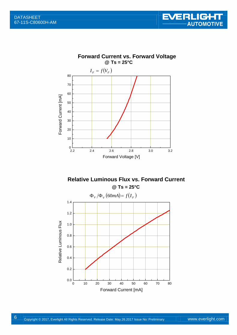
Forward Current vs. Forward Voltage @ Ts = 25°C
2.2 2.4 2.6 2.8 3.0 3.20
10
20
30
40
50
60
70
80
Forw
ard
Curr
en
t [m
A]
Forward Voltage [V]
Relative Luminous Flux vs. Forward Current
@ Ts = 25°C
0 10 20 30 40 50 60 70 800.0
0.2
0.4
0.6
0.8
1.0
1.2
1.4
Rela
tive L
um
inous F
lux
Forward Current [mA]
FVV IfmA 60
FF VfI
DATASHEET 67-11S-C80600H-AM
7 Copyright © 2017, Everlight All Rights Reserved. Release Date: May.26.2017 Issue No: Preliminary www.everlight.com
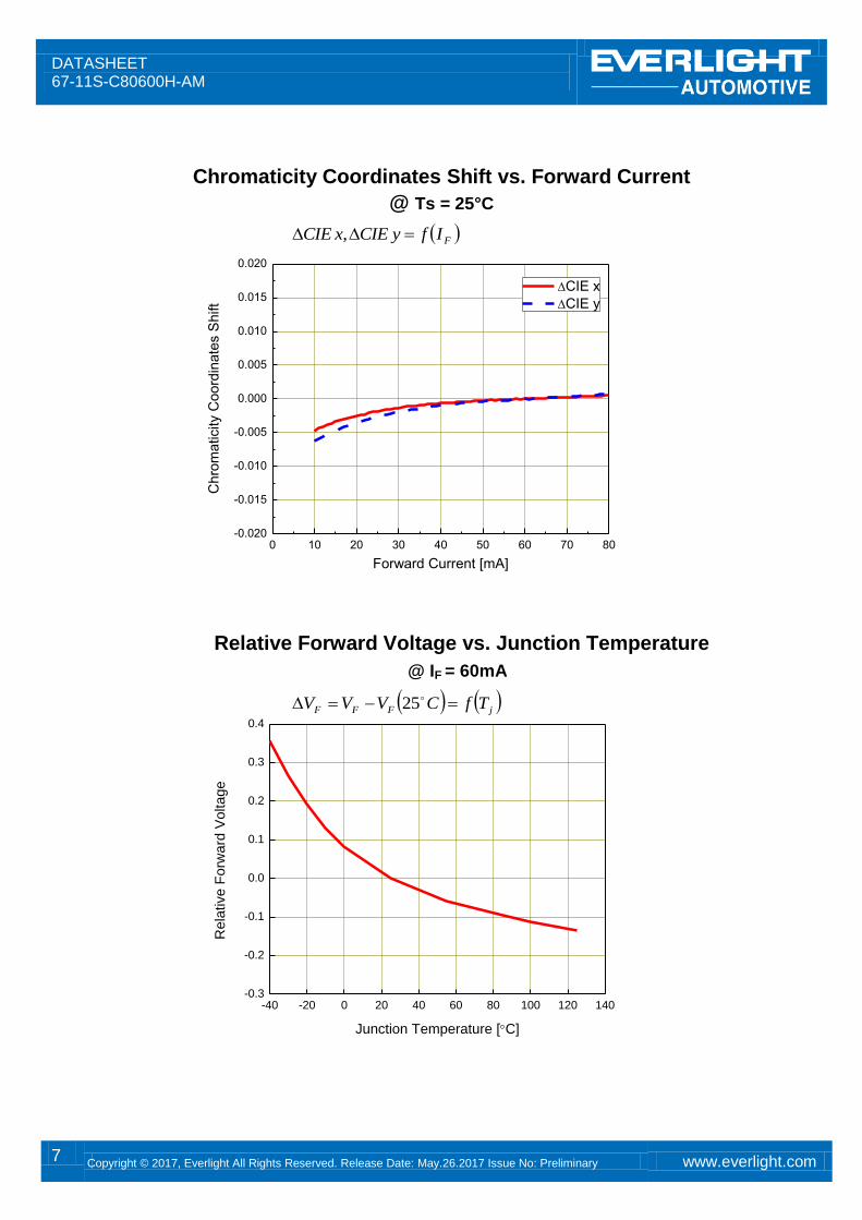
Chromaticity Coordinates Shift vs. Forward Current
@ Ts = 25°C
0 10 20 30 40 50 60 70 80-0.020
-0.015
-0.010
-0.005
0.000
0.005
0.010
0.015
0.020
Chro
maticity C
oord
inate
s S
hift
Forward Current [mA]
CIE x
CIE y
Relative Forward Voltage vs. Junction Temperature
@ IF = 60mA
-40 -20 0 20 40 60 80 100 120 140-0.3
-0.2
-0.1
0.0
0.1
0.2
0.3
0.4
Re
lative
Fo
rwa
rd V
olta
ge
Junction Temperature [C]
FIfyCIExCIE ,
jFFF TfCVVV 25

DATASHEET 67-11S-C80600H-AM
8 Copyright © 2017, Everlight All Rights Reserved. Release Date: May.26.2017 Issue No: Preliminary www.everlight.com
Relative Luminous Flux vs. Junction Temperature
@ IF = 60mA
-40 -20 0 20 40 60 80 100 120 1400.0
0.2
0.4
0.6
0.8
1.0
1.2
1.4
1.6
Rela
tive L
um
inous F
lux
Junction Temperature [C]
Chromaticity Coordinates Shift vs. Junction Temperature
@ IF = 60mA
-40 -20 0 20 40 60 80 100 120 140-0.020
-0.015
-0.010
-0.005
0.000
0.005
0.010
0.015
0.020
CIE x
CIE y
Ch
rom
ati
cit
y C
oo
rdin
ate
s S
hif
t
Junction Temperature[oC]
jVV TfC 25
jTfyCIExCIE ,
DATASHEET 67-11S-C80600H-AM
9 Copyright © 2017, Everlight All Rights Reserved. Release Date: May.26.2017 Issue No: Preliminary www.everlight.com
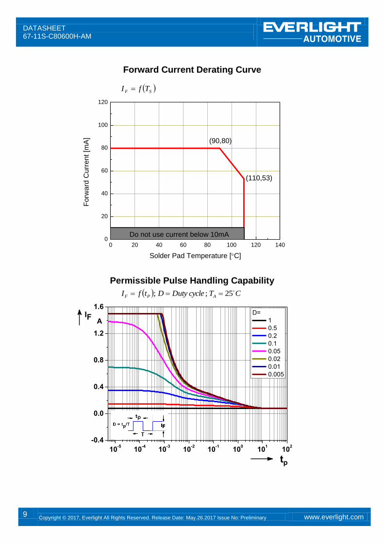
Forward Current Derating Curve
0 20 40 60 80 100 120 1400
20
40
60
80
100
120
Do not use current below 10mA
(110,53)
Forw
ard
Cu
rre
nt
[mA
]
Solder Pad Temperature [C]
(90,80)
Permissible Pulse Handling Capability
10-5
10-4
10-3
10-2
10-1
100
101
102
-0.4
0.0
0.4
0.8
1.2
1.6D=
1
0.5
0.2
0.1
0.05
0.02
0.01
0.005
tp
IFA
SF TfI
CTcycleDutyDtfI APF
25;;
DATASHEET 67-11S-C80600H-AM
10 Copyright © 2017, Everlight All Rights Reserved. Release Date: May.26.2017 Issue No: Preliminary www.everlight.com
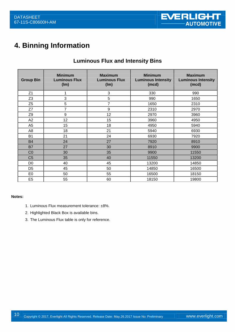
4. Binning Information
Luminous Flux and Intensity Bins
Notes:
1. Luminous Flux measurement tolerance: ±8%.
2. Highlighted Black Box is available bins.
3. The Luminous Flux table is only for reference.
Group Bin Minimum
Luminous Flux (lm)
Maximum Luminous Flux
(lm)
Minimum Luminous Intensity
(mcd)
Maximum Luminous Intensity
(mcd)
Z1 1 3 330 990
Z3 3 5 990 1650
Z5 5 7 1650 2310
Z7 7 9 2310 2970
Z9 9 12 2970 3960
A2 12 15 3960 4950
A5 15 18 4950 5940
A8 18 21 5940 6930
B1 21 24 6930 7920
B4 24 27 7920 8910
B7 27 30 8910 9900
C0 30 35 9900 11550
C5 35 40 11550 13200
D0 40 45 13200 14850
D5 45 50 14850 16500
E0 50 55 16500 18150
E5 55 60 18150 19800
DATASHEET 67-11S-C80600H-AM
11 Copyright © 2017, Everlight All Rights Reserved. Release Date: May.26.2017 Issue No: Preliminary www.everlight.com
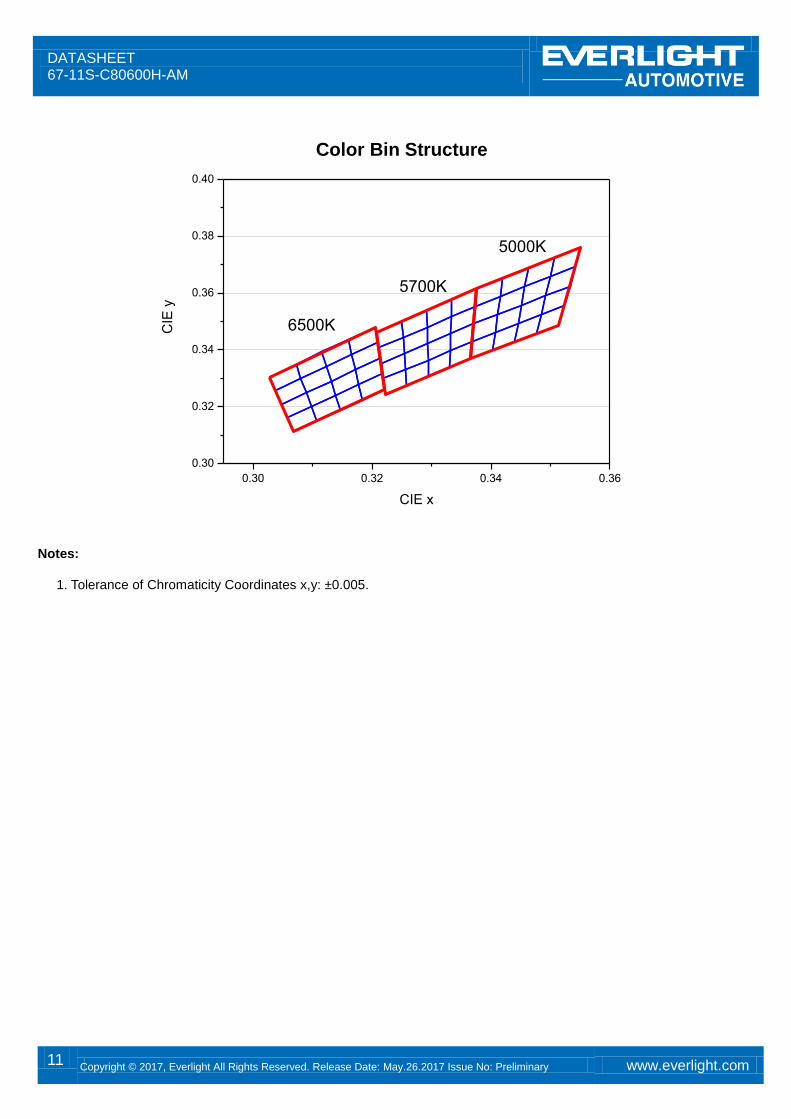
Color Bin Structure
0.30 0.32 0.34 0.36
0.30
0.32
0.34
0.36
0.38
0.40
6500K
5700K
5000K
C
IE y
CIE x
Notes:
1. Tolerance of Chromaticity Coordinates x,y: ±0.005.
DATASHEET 67-11S-C80600H-AM
12 Copyright © 2017, Everlight All Rights Reserved. Release Date: May.26.2017 Issue No: Preliminary www.everlight.com
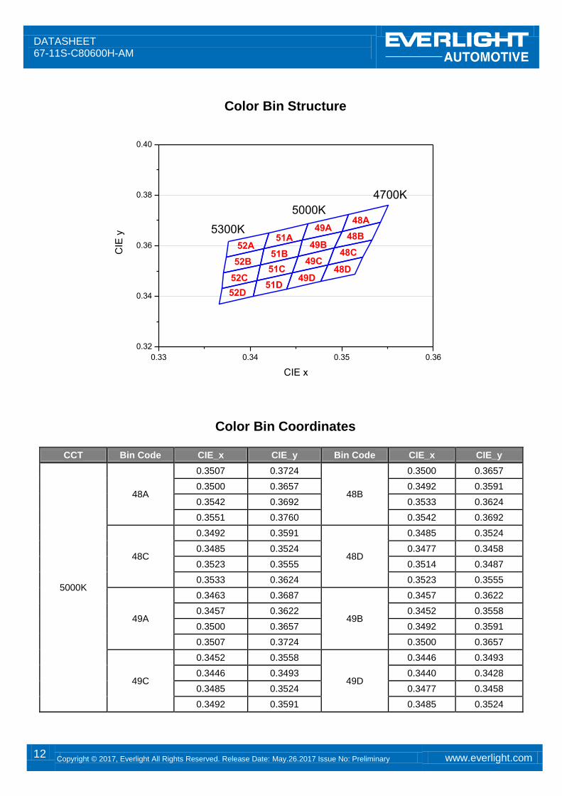
Color Bin Structure
0.33 0.34 0.35 0.36
0.32
0.34
0.36
0.38
0.40
5300K
5000K
52A51A
49A
4700K
48A
CIE
y
CIE x
52B51B
49B48B
52C51C
49C48C
52D51D
49D48D
Color Bin Coordinates
CCT Bin Code CIE_x CIE_y Bin Code CIE_x CIE_y
5000K
48A
0.3507 0.3724
48B
0.3500 0.3657
0.3500 0.3657 0.3492 0.3591
0.3542 0.3692 0.3533 0.3624
0.3551 0.3760 0.3542 0.3692
48C
0.3492 0.3591
48D
0.3485 0.3524
0.3485 0.3524 0.3477 0.3458
0.3523 0.3555 0.3514 0.3487
0.3533 0.3624 0.3523 0.3555
49A
0.3463 0.3687
49B
0.3457 0.3622
0.3457 0.3622 0.3452 0.3558
0.3500 0.3657 0.3492 0.3591
0.3507 0.3724 0.3500 0.3657
49C
0.3452 0.3558
49D
0.3446 0.3493
0.3446 0.3493 0.3440 0.3428
0.3485 0.3524 0.3477 0.3458
0.3492 0.3591 0.3485 0.3524

DATASHEET 67-11S-C80600H-AM
13 Copyright © 2017, Everlight All Rights Reserved. Release Date: May.26.2017 Issue No: Preliminary www.everlight.com
CCT Bin Code CIE_x CIE_y Bin Code CIE_x CIE_y
5000K
51A
0.3420 0.3652
51B
0.3415 0.3588
0.3415 0.3588 0.3411 0.3525
0.3457 0.3622 0.3452 0.3558
0.3463 0.3687 0.3457 0.3622
51C
0.3411 0.3525
51D
0.3407 0.3462
0.3407 0.3462 0.3403 0.3399
0.3446 0.3493 0.3440 0.3428
0.3452 0.3558 0.3446 0.3493
52A
0.3376 0.3616
52B
0.3374 0.3554
0.3374 0.3554 0.3371 0.3493
0.3415 0.3588 0.3411 0.3525
0.3420 0.3652 0.3415 0.3588
52C
0.3371 0.3493
52D
0.3369 0.3431
0.3369 0.3431 0.3366 0.3369
0.3407 0.3462 0.3403 0.3399
0.3411 0.3525 0.3407 0.3462
DATASHEET 67-11S-C80600H-AM
14 Copyright © 2017, Everlight All Rights Reserved. Release Date: May.26.2017 Issue No: Preliminary www.everlight.com
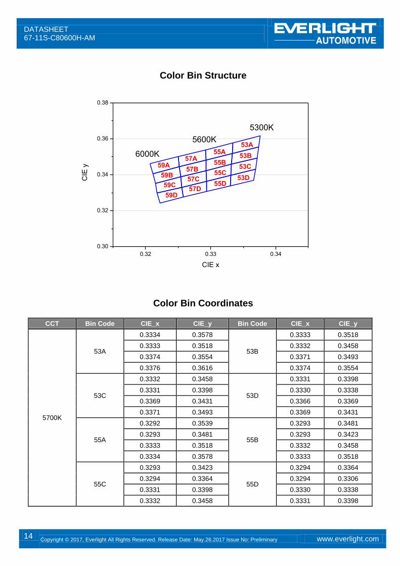
Color Bin Structure
0.32 0.33 0.34
0.30
0.32
0.34
0.36
0.38
6000K
5600K
59A57A
55A
5300K
53A
CIE
y
CIE x
59B57B
55B53B
59C57C
55C53C
59D57D
55D53D
Color Bin Coordinates
CCT Bin Code CIE_x CIE_y Bin Code CIE_x CIE_y
5700K
53A
0.3334 0.3578
53B
0.3333 0.3518
0.3333 0.3518 0.3332 0.3458
0.3374 0.3554 0.3371 0.3493
0.3376 0.3616 0.3374 0.3554
53C
0.3332 0.3458
53D
0.3331 0.3398
0.3331 0.3398 0.3330 0.3338
0.3369 0.3431 0.3366 0.3369
0.3371 0.3493 0.3369 0.3431
55A
0.3292 0.3539
55B
0.3293 0.3481
0.3293 0.3481 0.3293 0.3423
0.3333 0.3518 0.3332 0.3458
0.3334 0.3578 0.3333 0.3518
55C
0.3293 0.3423
55D
0.3294 0.3364
0.3294 0.3364 0.3294 0.3306
0.3331 0.3398 0.3330 0.3338
0.3332 0.3458 0.3331 0.3398
DATASHEET 67-11S-C80600H-AM
15 Copyright © 2017, Everlight All Rights Reserved. Release Date: May.26.2017 Issue No: Preliminary www.everlight.com
CCT Bin Code CIE_x CIE_y Bin Code CIE_x CIE_y
5700K
57A
0.3250 0.3501
57B
0.3252 0.3444
0.3252 0.3444 0.3254 0.3388
0.3293 0.3481 0.3293 0.3423
0.3292 0.3539 0.3293 0.3481
57C
0.3254 0.3388
57D
0.3256 0.3331
0.3256 0.3331 0.3258 0.3275
0.3294 0.3364 0.3294 0.3306
0.3293 0.3423 0.3294 0.3364
59A
0.3207 0.3462
59B
0.3211 0.3407
0.3211 0.3407 0.3215 0.3353
0.3252 0.3444 0.3254 0.3388
0.3250 0.3501 0.3252 0.3444
59C
0.3215 0.3353
59D
0.3218 0.3298
0.3218 0.3298 0.3222 0.3243
0.3256 0.3331 0.3258 0.3275
0.3254 0.3388 0.3256 0.3331
DATASHEET 67-11S-C80600H-AM
16 Copyright © 2017, Everlight All Rights Reserved. Release Date: May.26.2017 Issue No: Preliminary www.everlight.com
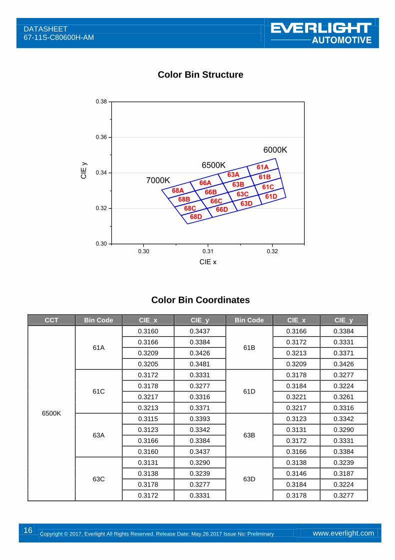
Color Bin Structure
0.30 0.31 0.32
0.30
0.32
0.34
0.36
0.38
7000K
6500K
68A66A
63A
6000K
61A
CIE
y
CIE x
68B66B
63B61B
68C66C
63C61C
68D66D
63D61D
Color Bin Coordinates
CCT Bin Code CIE_x CIE_y Bin Code CIE_x CIE_y
6500K
61A
0.3160 0.3437
61B
0.3166 0.3384
0.3166 0.3384 0.3172 0.3331
0.3209 0.3426 0.3213 0.3371
0.3205 0.3481 0.3209 0.3426
61C
0.3172 0.3331
61D
0.3178 0.3277
0.3178 0.3277 0.3184 0.3224
0.3217 0.3316 0.3221 0.3261
0.3213 0.3371 0.3217 0.3316
63A
0.3115 0.3393
63B
0.3123 0.3342
0.3123 0.3342 0.3131 0.3290
0.3166 0.3384 0.3172 0.3331
0.3160 0.3437 0.3166 0.3384
63C
0.3131 0.3290
63D
0.3138 0.3239
0.3138 0.3239 0.3146 0.3187
0.3178 0.3277 0.3184 0.3224
0.3172 0.3331 0.3178 0.3277
DATASHEET 67-11S-C80600H-AM
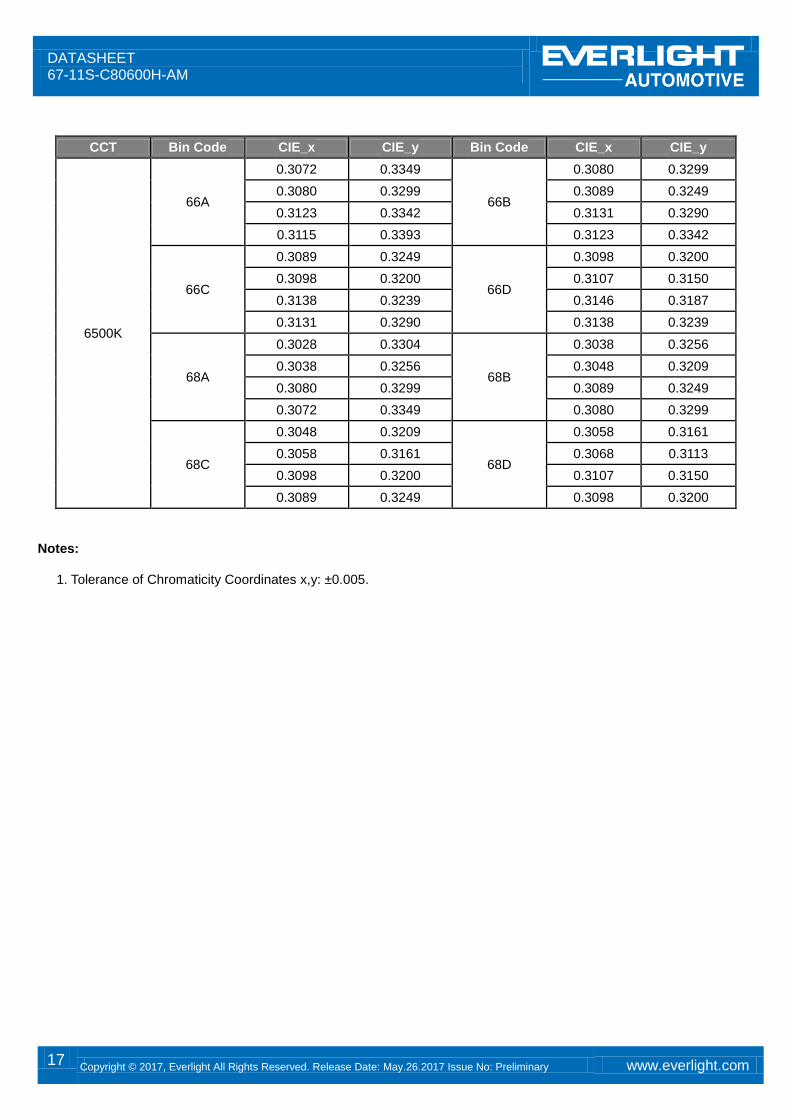
17 Copyright © 2017, Everlight All Rights Reserved. Release Date: May.26.2017 Issue No: Preliminary www.everlight.com
CCT Bin Code CIE_x CIE_y Bin Code CIE_x CIE_y
6500K
66A
0.3072 0.3349
66B
0.3080 0.3299
0.3080 0.3299 0.3089 0.3249
0.3123 0.3342 0.3131 0.3290
0.3115 0.3393 0.3123 0.3342
66C
0.3089 0.3249
66D
0.3098 0.3200
0.3098 0.3200 0.3107 0.3150
0.3138 0.3239 0.3146 0.3187
0.3131 0.3290 0.3138 0.3239
68A
0.3028 0.3304
68B
0.3038 0.3256
0.3038 0.3256 0.3048 0.3209
0.3080 0.3299 0.3089 0.3249
0.3072 0.3349 0.3080 0.3299
68C
0.3048 0.3209
68D
0.3058 0.3161
0.3058 0.3161 0.3068 0.3113
0.3098 0.3200 0.3107 0.3150
0.3089 0.3249 0.3098 0.3200
Notes:
1. Tolerance of Chromaticity Coordinates x,y: ±0.005.
DATASHEET 67-11S-C80600H-AM
18 Copyright © 2017, Everlight All Rights Reserved. Release Date: May.26.2017 Issue No: Preliminary www.everlight.com
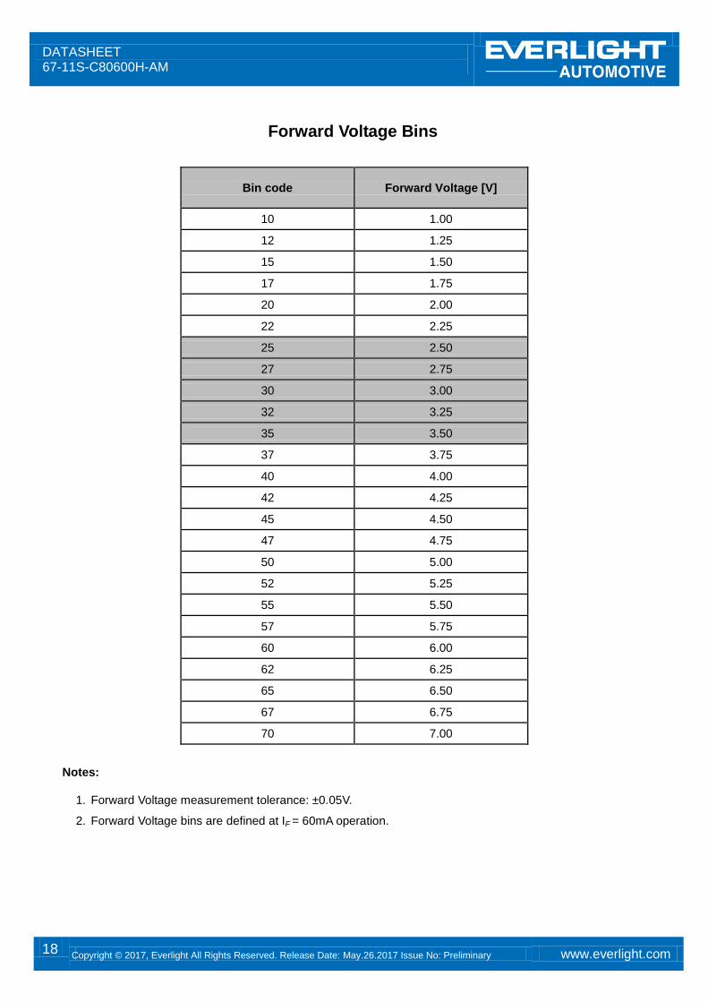
Forward Voltage Bins
Bin code Forward Voltage [V]
10 1.00
12 1.25
15 1.50
17 1.75
20 2.00
22 2.25
25 2.50
27 2.75
30 3.00
32 3.25
35 3.50
37 3.75
40 4.00
42 4.25
45 4.50
47 4.75
50 5.00
52 5.25
55 5.50
57 5.75
60 6.00
62 6.25
65 6.50
67 6.75
70 7.00
Notes:
1. Forward Voltage measurement tolerance: ±0.05V.
2. Forward Voltage bins are defined at IF = 60mA operation.
DATASHEET 67-11S-C80600H-AM
19 Copyright © 2017, Everlight All Rights Reserved. Release Date: May.26.2017 Issue No: Preliminary www.everlight.com
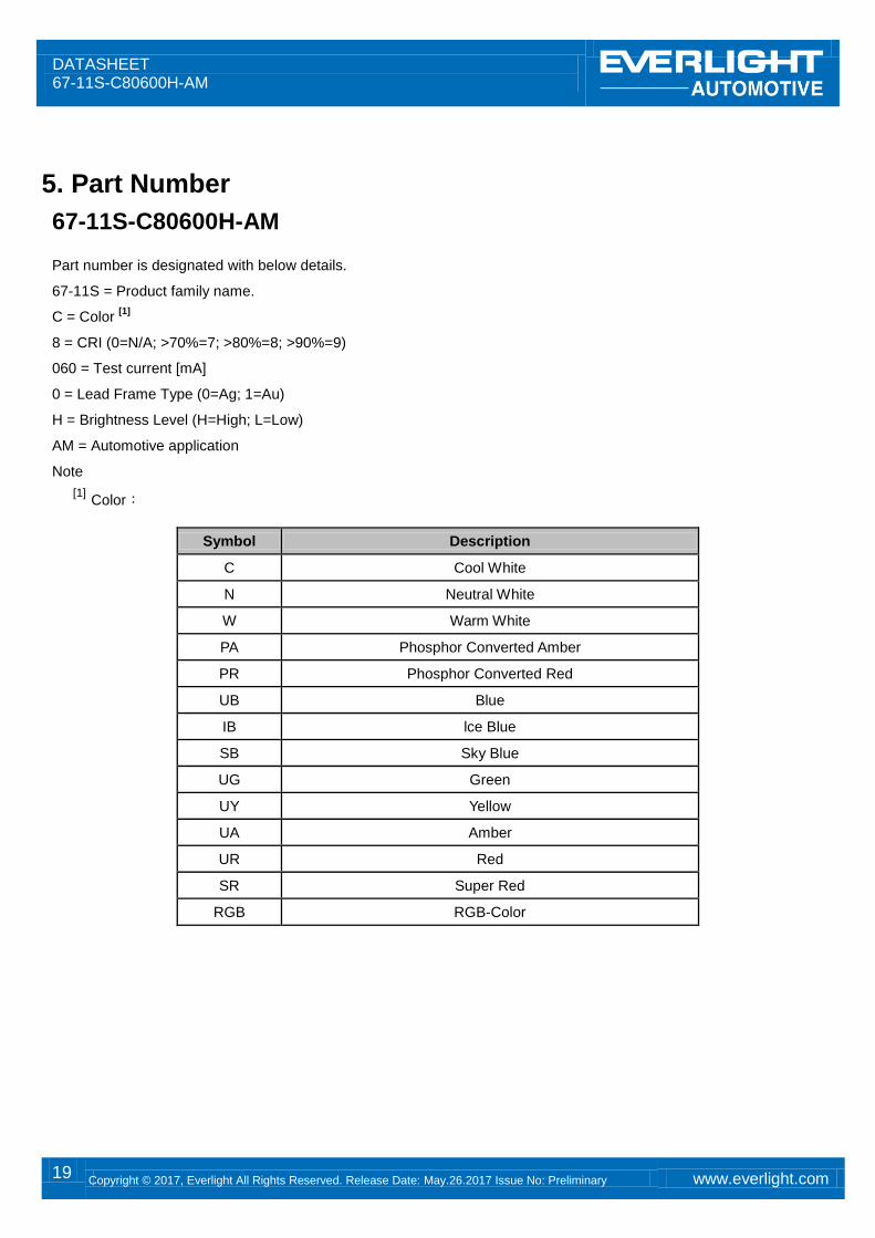
5. Part Number
67-11S-C80600H-AM
Part number is designated with below details.
67-11S = Product family name.
C = Color [1]
8 = CRI (0=N/A; >70%=7; >80%=8; >90%=9)
060 = Test current [mA]
0 = Lead Frame Type (0=Ag; 1=Au)
H = Brightness Level (H=High; L=Low)
AM = Automotive application
Note
[1] Color:
Symbol Description
C Cool White
N Neutral White
W Warm White
PA Phosphor Converted Amber
PR Phosphor Converted Red
UB Blue
IB lce Blue
SB Sky Blue
UG Green
UY Yellow
UA Amber
UR Red
SR Super Red
RGB RGB-Color
DATASHEET 67-11S-C80600H-AM
20 Copyright © 2017, Everlight All Rights Reserved. Release Date: May.26.2017 Issue No: Preliminary www.everlight.com
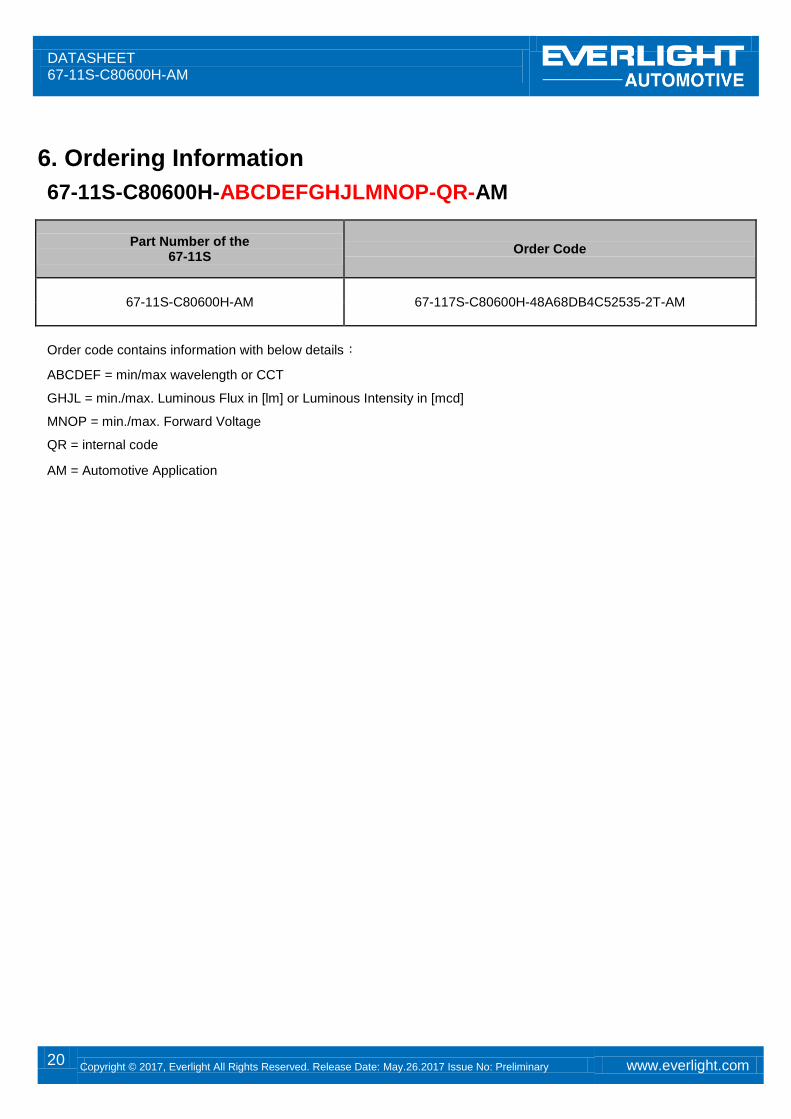
6. Ordering Information
67-11S-C80600H-ABCDEFGHJLMNOP-QR-AM
Part Number of the 67-11S
Order Code
67-11S-C80600H-AM 67-117S-C80600H-48A68DB4C52535-2T-AM
Order code contains information with below details:
ABCDEF = min/max wavelength or CCT
GHJL = min./max. Luminous Flux in [lm] or Luminous Intensity in [mcd]
MNOP = min./max. Forward Voltage
QR = internal code
AM = Automotive Application
DATASHEET 67-11S-C80600H-AM
21 Copyright © 2017, Everlight All Rights Reserved. Release Date: May.26.2017 Issue No: Preliminary www.everlight.com
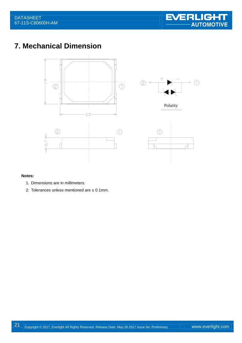
7. Mechanical Dimension
Polarity
Notes:
1. Dimensions are in millimeters.
2. Tolerances unless mentioned are ± 0.1mm.
DATASHEET 67-11S-C80600H-AM
22 Copyright © 2017, Everlight All Rights Reserved. Release Date: May.26.2017 Issue No: Preliminary www.everlight.com
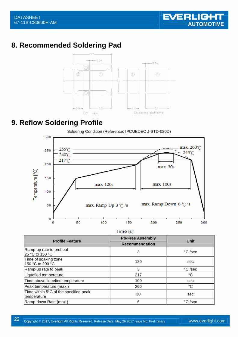
8. Recommended Soldering Pad Polarity
9. Reflow Soldering Profile
Soldering Condition (Reference: IPC/JEDEC J-STD-020D)
Profile Feature Pb-Free Assembly
Unit Recommendation
Ramp-up rate to preheat 25 °C to 150 °C
3 °C /sec
Time of soaking zone 150 °C to 200 °C
120 sec
Ramp-up rate to peak 3 °C /sec
Liquefied temperature 217 °C
Time above liquefied temperature 100 sec
Peak temperature (max.) 260 °C
Time within 5°C of the specified peak temperature
30 sec
Ramp-down Rate (max.) 6 °C /sec
DATASHEET 67-11S-C80600H-AM
23 Copyright © 2017, Everlight All Rights Reserved. Release Date: May.26.2017 Issue No: Preliminary www.everlight.com
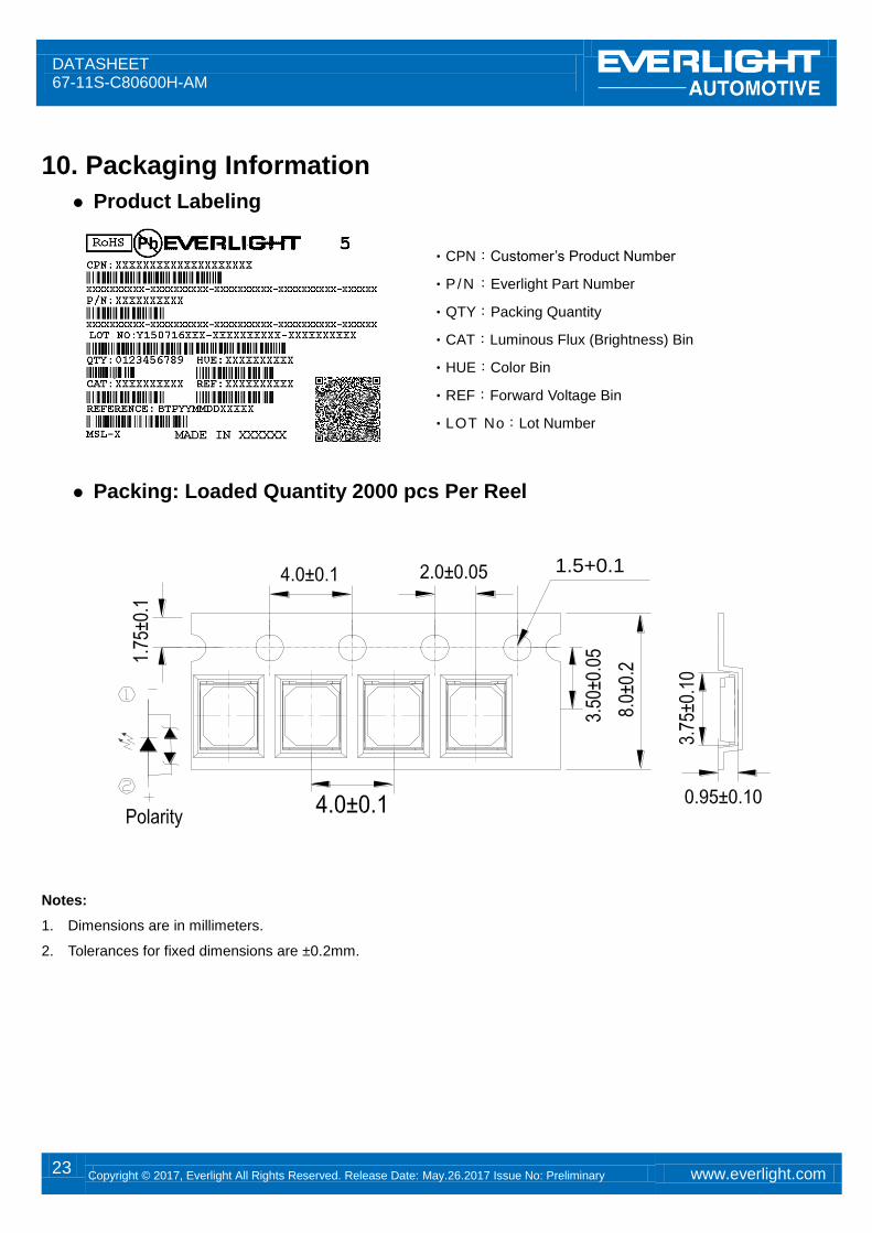
10. Packaging Information
Product Labeling
‧CPN:Customer’s Product Number
‧P/N:Everlight Part Number
‧QTY:Packing Quantity
‧CAT:Luminous Flux (Brightness) Bin
‧HUE:Color Bin
‧REF:Forward Voltage Bin
‧LOT No:Lot Number
Packing: Loaded Quantity 2000 pcs Per Reel
1.5+0.1
Progressive direction
Notes:
1. Dimensions are in millimeters.
2. Tolerances for fixed dimensions are ±0.2mm.
DATASHEET 67-11S-C80600H-AM
24 Copyright © 2017, Everlight All Rights Reserved. Release Date: May.26.2017 Issue No: Preliminary www.everlight.com
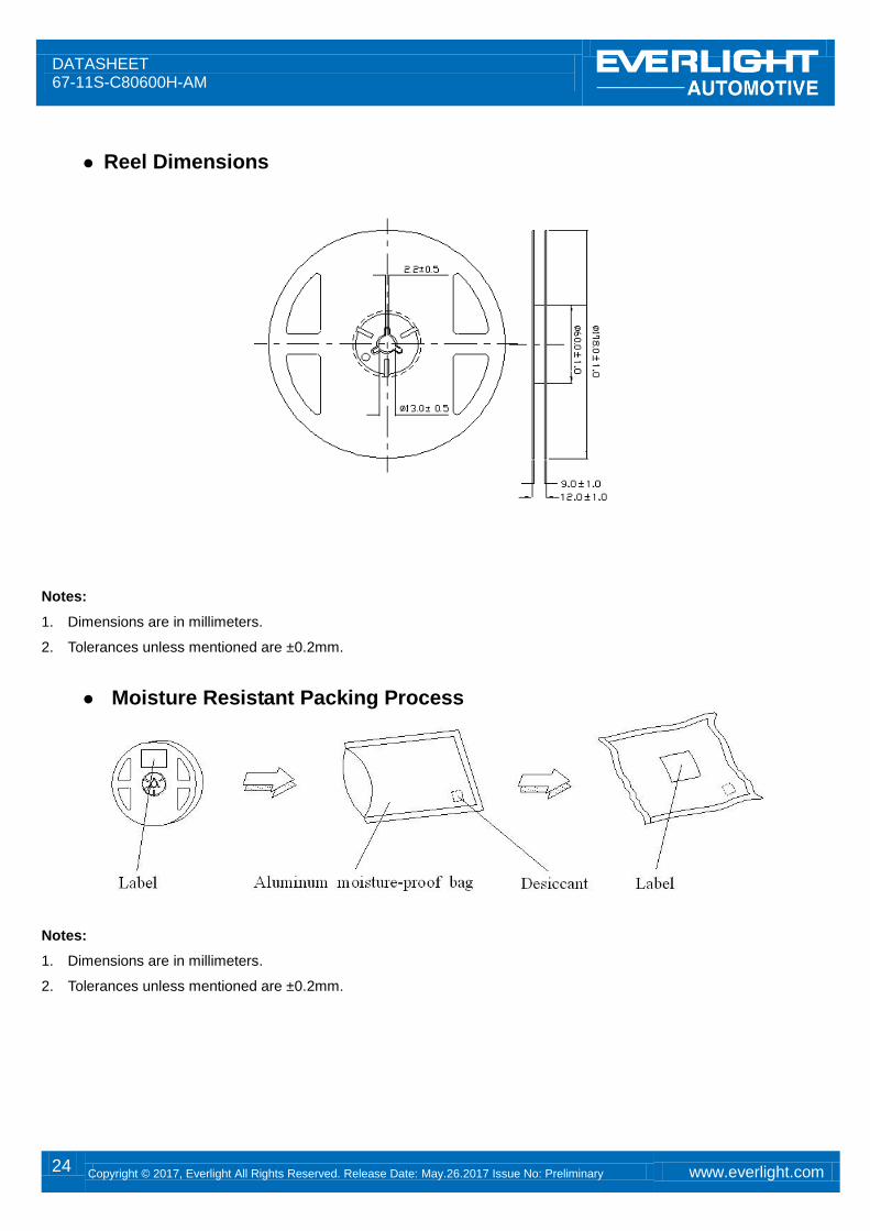
Reel Dimensions
Notes:
1. Dimensions are in millimeters.
2. Tolerances unless mentioned are ±0.2mm.
Moisture Resistant Packing Process
Notes:
1. Dimensions are in millimeters.
2. Tolerances unless mentioned are ±0.2mm.
DATASHEET 67-11S-C80600H-AM
25 Copyright © 2017, Everlight All Rights Reserved. Release Date: May.26.2017 Issue No: Preliminary www.everlight.com
11. Precaution for Use 1. Over-current-proof
Customer must apply resistors for protection; otherwise slight voltage shift will cause big current change (burn out will happen).
2. Assemblies Do not stack assemblies containing LEDs to prevent damage to the optical surface of LEDs. Forces applied to the
optical surface may result in the surface being damaged.
3. Soldering Condition 3.1 When soldering, do not put stress on the LEDs during heating. 3.2 After soldering, do not warp the circuit board.
4. Soldering Iron Each terminal is to go to the tip of soldering iron temperature less than 350℃ for 3 seconds within once in less than the soldering iron capacity 25W. Leave two seconds and more intervals, and do soldering of each terminal. Be careful because the damage of the product is often started at the time of the hand solder.
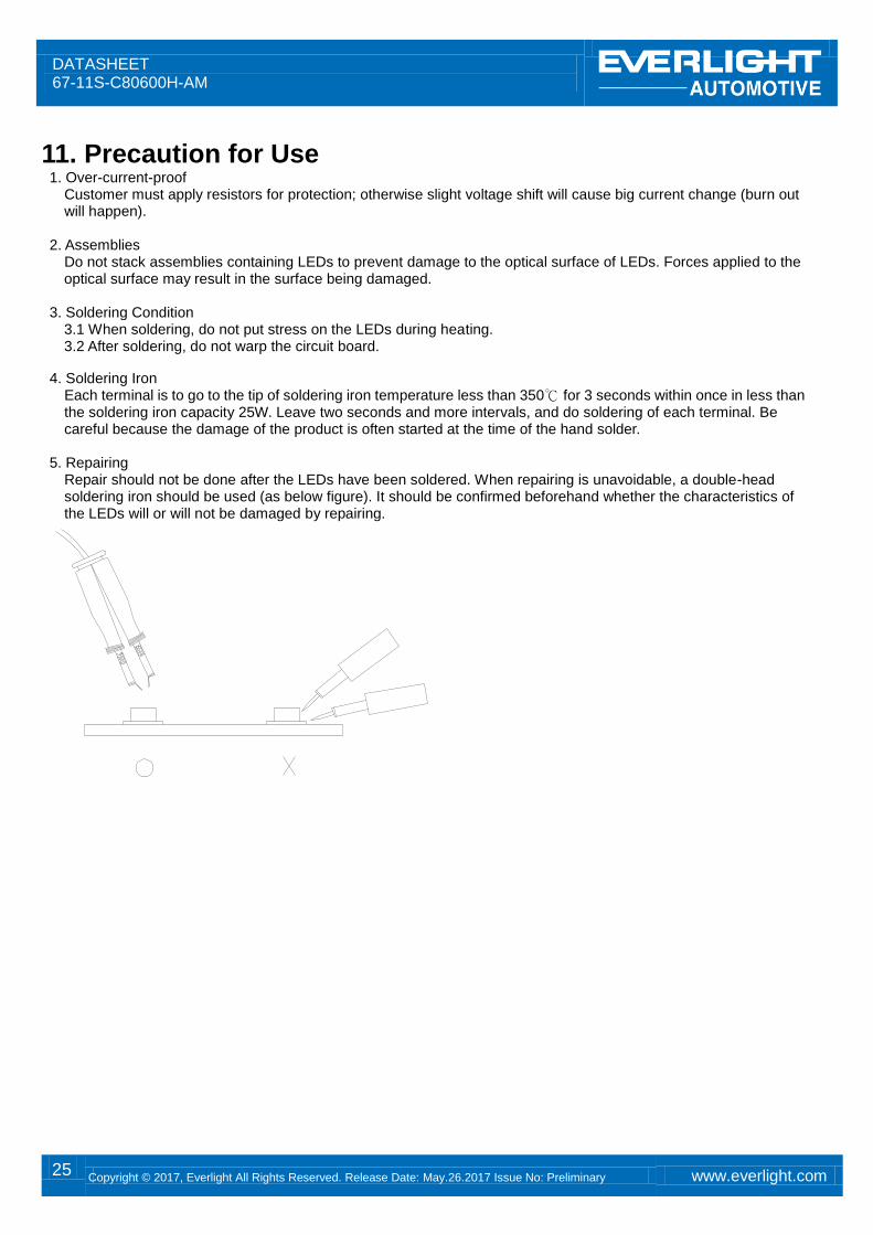
5. Repairing Repair should not be done after the LEDs have been soldered. When repairing is unavoidable, a double-head soldering iron should be used (as below figure). It should be confirmed beforehand whether the characteristics of the LEDs will or will not be damaged by repairing.
DATASHEET 67-11S-C80600H-AM
26 Copyright © 2017, Everlight All Rights Reserved. Release Date: May.26.2017 Issue No: Preliminary www.everlight.com
Revision History
Current version: May.26.2017
Issue No:
Version: 1.0
Created by: Sherry Chen
Rev. Subjects (major change in previous version) Modified date
1.0 Standard data sheet 2017/05/26