
EK307A1 F17 Lecture08
53
EK 307: Electric Circuits Fall 2017 Lecture 8 Sep 28, 2017 Prof. Miloš Popović Departmentof Electrical and Computer Engineering Boston University
Transcript of EK307A1 F17 Lecture08

EK 307:Electric Circuits
Fall 2017
Lecture 8Sep 28, 2017
Prof. Miloš PopovićDepartment of Electrical and Computer Engineering
Boston University

Administrivia
• Homework 1 back

Lecture 7 (last time) reminder:
1. Mesh current analysis (2 examples)
2. Linearity, superposition3. Dependent sources, transistor model circuits

Lecture 8 (today): What you should know at end of this lecture1. Source transformations, Thevenin and Norton
theorems2. Equivalent resistance (max power transfer)

Review:Linearity, superposition, source transformation

Linearity
• Any output is proportional to any input

Superposition
• For multiple inputs (e.g. sources):• Any output is the sum of outputs due to each input turned on separately• “Turned off input” means V=0 for voltage sources, I=0 for current sources.• Dependent sources stay.
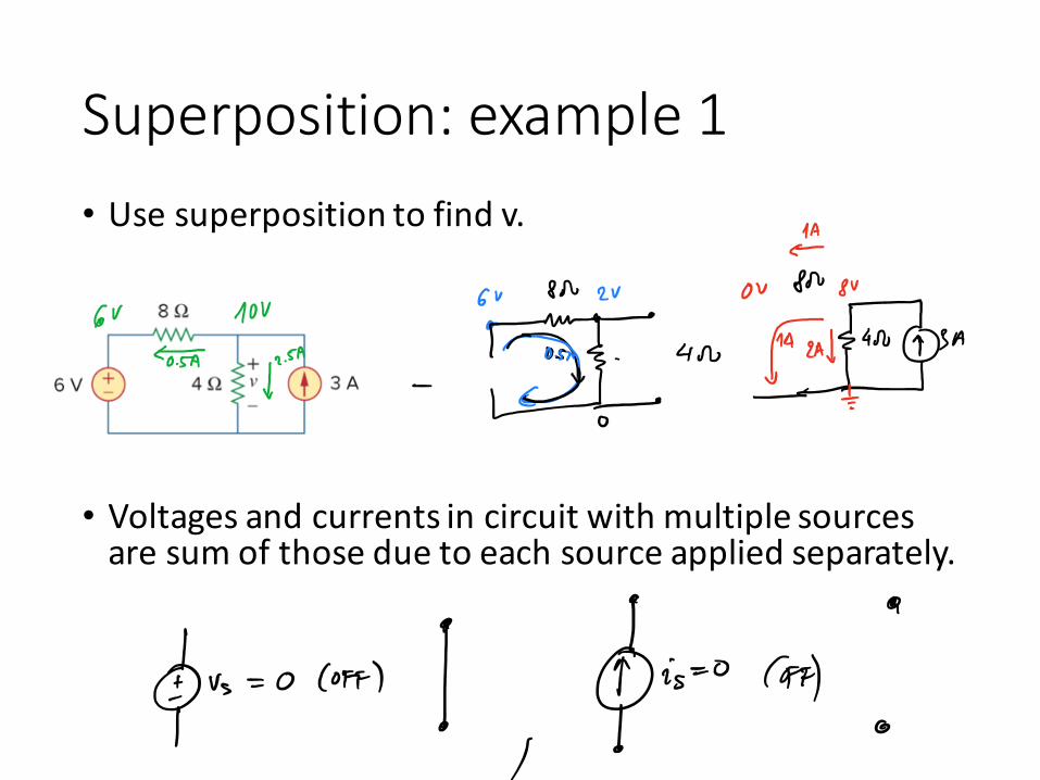
Superposition: example 1• Use superposition to find v.
• Voltages and currents in circuit with multiple sources are sum of those due to each source applied separately.

Superposition: example 2

Source transformations

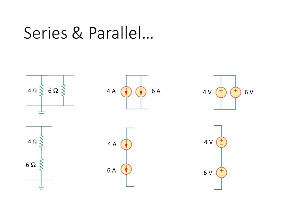
Series & Parallel…
6 Ω

Series & Parallel…
6 Ω
6 Ω

Series & Parallel…
6 Ω
6 Ω
4 A 6 A

Series & Parallel…
6 Ω
6 Ω
4 A 6 A
4 A
6 A

Series & Parallel…
6 Ω
6 Ω
4 A 6 A
4 A
6 A
4 V
6 V
Series & Parallel…
6 Ω
6 Ω
4 A 6 A
4 A
6 A
4 V 6 V
4 V
6 V

Series & Parallel…
6 Ω
6 Ω
4 A 6 A
4 A
6 A
4 V 6 V
4 V
6 V
How can these be impossible? Can’t I just go in the lab and connect them up…?

Real sources have internal resistance
For a voltage source, it *has* to be in series. See next few slides. A parallel resistor does nothing. In the limit where R approaches 0 ohms, we recover the ideal source.


Source transformations: IV curve
A voltage source can be replaced by a current source, with the connected load circuit unable to tell the difference between them! See next slide.


Source transformations

Source transformations

Source transformations: exampleFind vo.


Maximum power transfer


Let’s see what happens… (let’s plot power burned in RL vs load resistance RL in Mathematica).
At low load resistances RL, the voltage is near zero and the current is higher.At high load resistances RL, the voltage is equal to the source voltage, but the current approaches zero.In both cases, the power P=vi approaches zero.In between at some arbitrary RL, both voltage and current can be non-‐zero, so it seems there is a sweet spot: an ideal choice of resistance to dissipate the most power.
vv
RL
RL
RL
PP
ii
Sweet spot

Thevenin and Norton Theorems

Thevenin Theorem

Thevenin Theorem
Thevenin’s theorem states that a linear two-‐terminal circuit can be replaced by an equivalent circuit consisting of a voltage source VTh in series with a resistor RTh, where VTh is the open-‐circuit voltage at the terminals and RTh is the input or equivalent resistance at the terminals when the independent sources are turned off.

Thevenin Theorem

Thevenin exampleFind the Thevenin equivalent of the circuit to the left of the terminals a-‐b. Then find the current through RL = 6, 16, and 36 Ω.


Thevenin exampleFind the Thevenin equivalent of the circuit to the left of the terminals a-‐b. Then find the current through RL = 6, 16, and 36 Ω.

Thevenin example 2

Norton Theorem
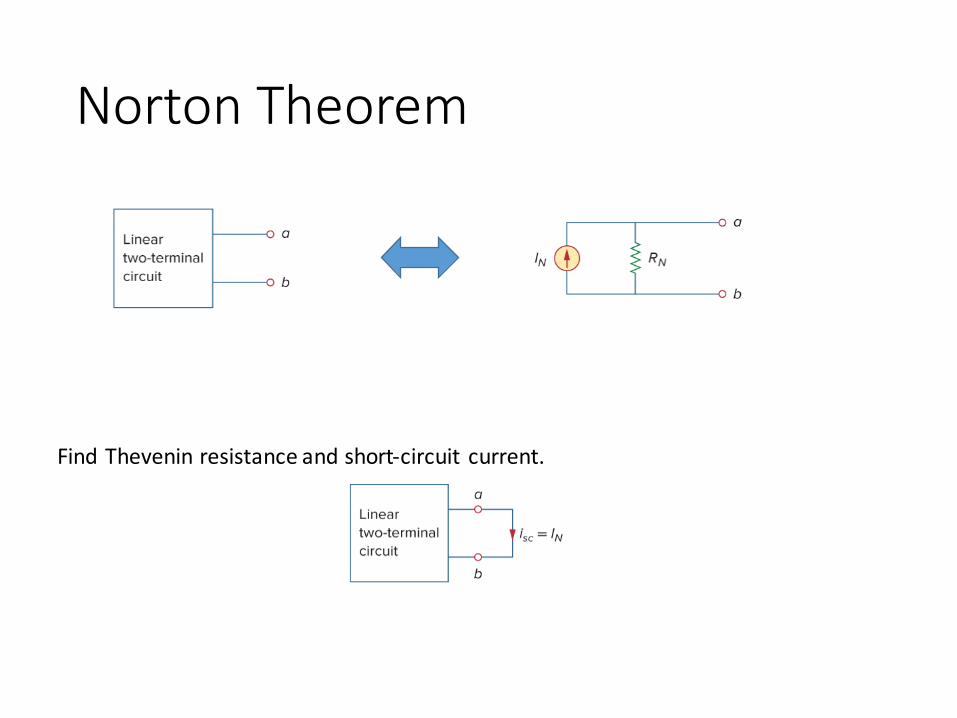
Norton Theorem
Find Thevenin resistance and short-‐circuit current.

Source modeling, bridge circuits, interface ccts

Models of real sources

Models of real sources

ExampleThe terminal voltage of a voltage source is 12 V when connected to a 2-‐W load. When the load is disconnected, the terminal voltage rises to 12.4 V. (a) Calculate the source voltage vs and internal resistance Rs. (b) Determine the voltage when an 8-‐Ω load is connected to the source.

Operational Amplifiers (Op-‐Amps)

Op-‐Amps

Op-‐Amps

Op-‐Amps

Op-‐Amps

We skipped in this lecture…
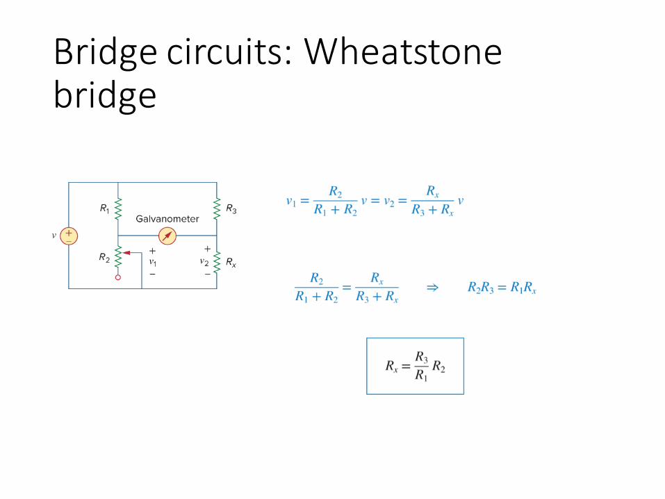
Bridge circuits: Wheatstone bridge

Example: unbalanced bridge
Find the current through the galvanometer.


![Lecture08 OMNetTutorial.ppt [호환 모드]](https://static.fdocuments.net/doc/165x107/61abcdb10f582e004b2e8069/lecture08-.jpg)