Eindhoven University of Technology MASTER The design of a ... fileThe design of a simulator...
73
Eindhoven University of Technology MASTER The design of a simulator generator for parallel architectures Waucomont, M.J.P.H. Award date: 1993 Link to publication Disclaimer This document contains a student thesis (bachelor's or master's), as authored by a student at Eindhoven University of Technology. Student theses are made available in the TU/e repository upon obtaining the required degree. The grade received is not published on the document as presented in the repository. The required complexity or quality of research of student theses may vary by program, and the required minimum study period may vary in duration. General rights Copyright and moral rights for the publications made accessible in the public portal are retained by the authors and/or other copyright owners and it is a condition of accessing publications that users recognise and abide by the legal requirements associated with these rights. • Users may download and print one copy of any publication from the public portal for the purpose of private study or research. • You may not further distribute the material or use it for any profit-making activity or commercial gain
Transcript of Eindhoven University of Technology MASTER The design of a ... fileThe design of a simulator...

Eindhoven University of Technology
MASTER
The design of a simulator generator for parallel architectures
Waucomont, M.J.P.H.
Award date:1993
Link to publication
DisclaimerThis document contains a student thesis (bachelor's or master's), as authored by a student at Eindhoven University of Technology. Studenttheses are made available in the TU/e repository upon obtaining the required degree. The grade received is not published on the documentas presented in the repository. The required complexity or quality of research of student theses may vary by program, and the requiredminimum study period may vary in duration.
General rightsCopyright and moral rights for the publications made accessible in the public portal are retained by the authors and/or other copyright ownersand it is a condition of accessing publications that users recognise and abide by the legal requirements associated with these rights.
• Users may download and print one copy of any publication from the public portal for the purpose of private study or research. • You may not further distribute the material or use it for any profit-making activity or commercial gain

The Design ofA Simulator Generator for
Parallel Architectures
M.J.P.R. Waucomont
Department of Electrical EngineeringDigital Information Systems SectionEindhoven University of Technology
October 25, 1993
Coach: ir. W.J. WithagenSupervisor: prof. ir. M.P.J. Stevens
The department of Electrical Engineering of the Eindhoven University of Technology does notaccept any responsibility regarding the contents of student projects and graduation reports.

Abstract
This paper reports the research into enhancing the existing sequential simulator generator SIMGEN (and the accompanying sequential processor descriptionlanguage SIMDES) to accomodate the simulation of parallel processors. In thecontext of this report, 'parallel' refers to instruction level parallelism within asingle processor. The research deals with finding a new model and the impact ofthis model on the description language.
Adapting the simulator generator requires finding a new simulation model. Inorder to be able to simulate architectures with instruction level parallelism, themodel must incorporate implementation details such as pipeline registers andcontrol. Control consists of a control unit which resembles the control unit of asequential implementation plus additional units like a hazard detection unit, anda forwarding unit. It also contains provisions to cope with control hazards as wellas interrupts.
Research on the description language has shown that the modification has a severeimpact on the nature of the description language. For sequential simulation thedescription of the behavior of the instructions plays the key role. Description ofthe behavior of the instructions suffices to describe the behavior of a sequentialprocessor. For parallel processors the behavioral description of the instructionsmust be replaced by a description of the behavior of the implementation. Thisrequires descriptive constructs to describe the behavior of the pipe stages and thecontrol units.
This report describes the complications involved in describing and simulatinghigh performance pipelines. First the theory of pipelining is presented. Then,the hardware required is shown at an appropriate level of abstraction. Finally,the problem space is narrowed down by choosing a simplified example in orderto be able to present a definition of the description language.

Contents
1 Introduction
1.1 Microprocessor Simulation
1.2 SIMPROACH 0
1.3 Levell ....
1.4 A Parallel Simulator Generator at Levell
2 Levels of Abstraction
2.1 An Extremely Abstract Model.
2.2 An Implementation Oriented Model .
3 The Theory of Pipelining
3.1 Pipelining ..... 0 •••••••••
3.2 Performance of Pipelined Processors
3.3 Pipeline Hazards .....
3.3.1 Structural Hazards
3.3.2 Data Hazards . .
3.3.3 Control Hazards.
3.4 Interrupts .
3.5 Multicycle Operations
4 The Hardware
4.1 Adding Implementation Details
4.1.1 Sequential Implementation .
4.1.2 Unfolding the Datapath ..
4.1.3 Parallel Implementation ..
4.1.4 The Main Control of a Pipelined Datapath .
III
1
1
1
2
4
5
5
6
9
9
11
13
13
15
17
18
20
23
23
24
25
27
29

IV
4.2 The Other Control Units.
4.2.1 Data Hazards ..
4.2.2 Control Hazards.
4.2.3 Interrupts....
4.2.4 Parallel Function Units.
5 Describing and Simulating the Hardware
5.1 Terminology and Conventions .
5.2 A Primitive Model .
5.2.1 What Is Wrong with the Primitive Model
5.3 The Improved Model
5.3.1 Control '"
5.3.2 Data Hazards
5.3.3 Forwarding .
5.3.4 Branch Hazards .
5.3.5 Interrupts....
5.3.6 Putting it All Together .
6 The Language
6.1 Pipeline Registers.
6.2 Pipe Stages . . . .
6.2.1 Main Control
6.3 Control Units
6.4 One Cycle
7 Conclusions
7.1 Effect on the Model .
7.2 Effect on the Language
7.3 Recommendations...
A SimDes Grammar and Production rules
CONTENTS
31
31
32
32
32
35
36
36
39
40
42
46
49
50
50
51
53
54
55
55
56
56
57
57
58
59
61

Chapter 1
Introduction
"Simulare certe est hominis"
(To simulate is certainly a human trait)Terentiu8, Adelphi 734
1.1 Microprocessor Simulation
Over the past years simulation of microprocessor architectures has become in
creasingly important. Designers of microprocessors want to be able to evaluatethe performance of an architecture prior to its implementation. This evaluationcan be done at different levels of abstraction.
1.2 SIMPROACH
One of the current research projects at the Digital Information Systems Section ofthe department of Electrical Engineering at the Eindhoven University of Technology is the SIMulator design system for PROcessor ArCHitectures (SIMPROACH).SIMPROACH will become a toolkit that can be used to obtain quantitative information about the performance of different microprocessor architectures. InSIMPROACH three levels of abstraction are distinguished. Increasing level numbers indicate an increasing level of detail and a decreasing level of abstraction.
1

2 CHAPTER 1. INTRODUCTION
Level 0 is represented by the Architecture Workbench [BCFZ89, MuI90], a processor performance analysis system developed at the Stanford University ComputerScience Laboratory. At this level only the elementary processor characteristicsare described. Slight alterations of these characteristics immediately translateinto changes of the simulation results. This tool is used to get a first impressionof the performance of an architecture.
Levell is used to model the Instruction Set Architecture (ISA). At this levelthere is minimal information regarding the implementation of the processor. Itsbehavior is specified by its instructions and the resources on which it operates,like registers and memory. The result of the research done so far is a sequentialinstruction set simulator generator [Tak92]. Takken's work uses a description ofthe architecture to produce a simulator for it.
Level 2 will be used to model the processor implementation. At this level eithera more detailed behavioral or even a structural simulation using a hardwaredescription language like VHDL or IDaSS will be provided.
Currently, little research regarding Level 2 has been done. The research describedin this report focusses on the possibilities of simulating processors with instructionlevel parallelism at Level 1 by adding a little bit more information about theimplementation to the sequential description.
1.3 Levell
Distinguishing different levels of abstraction is the way to cope with the complexity of the design of microprocessors. The Instruction Set Architecture or ISA isa very important interface between the levels of abstraction. It is the interfacebetween the hardware and the low-level software. Often the ISA is defined as theabstraction or definition of the system as seen by a machine language programmer or compiler writer. It is considered to be the definition of the conceptualstructure and the functional behavior of a processor as opposed to factors suchas the processor's logic design and circuit technology.
The approach most often found in literature to gather information at this levelof abstraction is to describe the architecture in a description language [MJ76,Cor8I, KT87, Tak92]. Either the description is interpreted or a simulator for thearchitecture is generated. In the case where a simulator is generated, it bears

1.3. LEVEL 1 3
a model of the processor in it that is chosen by the designer of the simulatorgenerator, and not by the designer of the architecture. This type of simulatorthus has a fixed number of execution phases, for example Instruction Fetch (IF),DEcode (DE), and EXecute (EX). This division into phases limits the designer'sfreedom in taking decisions.
Sequential simulators use this three stage cycle: IF, DE and EX. The phasesare executed sequentially and repeatedly, until either the end of the code to besimulated is reached or program execution is interrupted to monitor the simulation progress. Executing IF, DE and EX simulates the behavior of exactly oneinstruction.
In the instruction fetch phase the instruction is fetched from the simulator'smemory. In the decode phase the instruction type is determined and the appropriate syllables are extracted. There are many ways to recognize the differentinstruction types. Takken discusses different instruction decoding strategies inhis Master's thesis [Tak92]. In the execute phase the behavior of the instructionis simulated by calling the appropriate function.
Front End Back End
BEG Simulator
D program
UtileSimGen
Figure 1.1: Overview of the components of LevelL
Takken recently finished a simulator generator. It generates simulators that workaccording to the principles just described. The simulator generator is called SIMulator GENerator (SIMGEN). It uses an input language called processor SIMulation DEScription language (8IMDES). The output is C code that implementsthe architecture as well as a mechanism to gather statistics.
On Level 1 of 81M PROACH the information regarding the performance of an

4 CHAPTER 1. INTRODUCTION
architecture is gathered by simulating instructions on such a generated simulator. Benchmarks are compiled to obtain executables consisting of a sequenceof instructions to be simulated. The term 'benchmarks' should be taken in thebroadest sense of the word. A benchmark is a set of programs designed to getan overall impression of the performance of a processor. The compiler back endis generated by a so called Back End Generator (BEG) which, just like the simulator generator, has a description of the architecture as its input. Right nowthese two descriptions are different, but for future versions a generic architecturedescription for the simulator generator as well as the back end generator will bedesigned.
At the time of this writing, an ANSI C front end for the compiler is finished. SIMGEN is being tested, with SIMDES getting a lot of attention. Several processorsare being modelled in this language to determine the usability of the languagerather than to test the suitability of SIMGEN.
1.4 A Parallel Simulator Generator at Levell
The rest of this report describes the research done to investigate the possibilitiesto develop a new simulator generator for SIMPROACH, to be called Parallel Simulator Generator (PSIMGEN), and a new description language, Parallel SimulationDescription Language (PSIMDES). The simulators generated by PSIMGEN willbe used to gather information about the parallel execution of instructions, suchas Clocks Per Instruction (CPI), information about pipeline stalls, etc. In thecontext of SIMPROACH this is the logical next step after the simulators generatedby SIMGEN, which only perform a purely functional simulation of instructionsand provide information like instruction count, register usage, etc.
In order to be able to simulate parallel architectures an appropriate model of aprocessor has to be developed. In this report, first an indication of the level ofabstraction is given. Much attention is paid to the theory of pipelining. Then, anindication is given of the amount of implementation detail required to correctlymodel pipelined processors.
This information is used to complete a detailed design of a model and a description language for a simplified example. This can be a guideline for a possibleimplementation, but it also indicates how rapidly the complexity of the modeland the language increase when more detail is added.

Chapter 2
Levels of Abstraction
"People here don't know the art of leveling"Bruce Watson, Stratums Eind, 1992
An important complication in defining a suitable model for the simulation of aprocessor with instruction level parallelism, is to reach the right level of abstraction within the limits set by Levell. This chapter shows two different abstractionlevels at which a processor can be viewed. Both are extremes. For ease of explanation a sequential implementation is used, but the line of reasoning can beextended to the more complicated case of an implementation with instructionlevel parallelism.
2.1 An Extremely Abstract Model
The von Neumann architecture (Figure 2.1) is the predominant model of computer architectures. There is one read-write memory which contains both dataand instructions. This memory is addressable by location. The Central Processing Unit (CPU) or processor executes instructions from consecutive locationsunless an instruction modifies the control flow explicitly.
Von Neumann's model therefore is strictly sequential. A simulator based onthis model fetches an instruction, decodes it, and finally applies the appropriateoperations on the resources-registers, memory, and I/O ports. All instructions
5

6 CHAPTER 2. LEVELS OF ABSTRACTION
t...adresses MEWRY
vInstruction ninstruction n+1branch Instr. -
'" 7
Instruction n+3 i+-
.A ....CPU dala & Instructions
'I vdatailem
Figure 2.1: The von Neumann architecture.
are executed sequentially in the same manner. This describes the behavior of theprocessor. Basically, this is the model as used by Takken [Tak92].
The information about the architecture that is required to generate a simulatorof this type can be split into three categories. The first category describes theresources. The second category describes the layout of the instruction types, sothey can be recognized by the decode portion of the simulator. The last categoryprovides a functional description of the behavior of each instruction type. Thisdescription is used in the execute section to simulate the instruction's behavior.
The von Neumann model results in simulators that stress the importance of theinstruction set. More exactly, the importance of the functional specification of theeffect of the instructions. The model itself is implicitly present in the simulator.The input of the simulator generator consists mainly of the semantics of theinstructionset.
2.2 An Implementation Oriented Model
The processor is the part that executes the instructions. It consists of a controlunit and a datapath. The datapath is the part of the processor through whichdata flows. It includes functional units such as an Arithmetic and Logic Unit(ALU) as well as registers that may contain data, all organized around buses. Abus is a shared path between registers and/or functional units.

2.2. AN IMPLEMENTATION ORIENTED MODEL 7
The control unit controls the actions of the datapath during every clock cycleof the execution of any instruction. The behavior of the control unit can bedescribed by a finite state machine (with output-as in a Mealy or a Mooremachine), which changes state each clock cycle. Operations to be performedare associated with the states. Each instruction takes several clock cycles tocomplete. If we consider the processor to be a finite state machine, the contentsof the datapath determines the state the processor is in.
HardwiredLogic
Control linesto Datapath
n
MicroprogramMemory
Control linesto Datapath
n
k
Inputs fromDatapath
2 Ik+l+m) entries. m+n bits wide
Inputs fromDatapath
Figure 2.2: Hardwired versus Microprogrammed Control.
There are two major techniques for implementing the control unit. The firstis called hardwired control. In this technique the opcode field of the currentinstruction is fed into the hardwired control, together with the previous stateand some control inputs from the datapath. This results in a new state and incontrol signals that tell the datapath how to manipulate the data. Hardwiredcontrols tend to be large. Straightforward implementation would require a tableof several megabytes of Read Only Memory (ROM). Fortunately this is in generala sparse table, so its size can be reduced by keeping only the rows with uniqueinformation. This approach increases the complexity of the address decodinglogic. The implementation is known as a Programmed Logic Array (PLA).
Further reduction of hardware requirements can be achieved by using computeraided design programs to minimize the number of minterms. Yet another thingthat has to be taken in account here is that the size of the PLA also dependson the assignment of ordinal numbers to the states. There are computer-aideddesign programs that help to assign similar state numbers to states that performsimilar operations. This reduces the size of the PLA considerably. Lastly, theinstruction bits are also inputs to the control PLA. Just like the numbering ofstates, the selection of appropriate opcodes affects the cost of control.

8 CHAPTER 2. LEVELS OF ABSTRACTION
The second technique is called microprogrammed control. Essentially the controlunit is implemented as a miniature computer with its own instruction set. Itconsists of a table that specifies the control of the datapath and a second tablethat determines the control flow at the micro level. Thus, the microinstructionscalled this way by their inventor M. Wilkes in 1949 [Wi169]-specify all the controlsignals for the datapath, plus the ability to decide which microinstruction shouldbe executed next.
In this case the control unit is an interpreter for the instruction set, written forthe microarchitecture. The structure of the resulting microprogram resemblesthe state diagram that describes the processor very closely. For each state in thediagram there is one microinstruction.
The brief descriptions of these two ways for implementing control indicate thatchoosing a model that is very close to the hardware results in simulators that areboth extremely laborious to describe as well as very difficult to simulate. This isnot very useful in the context of simulation at SIMPROACH Levell. To obtain amore useful model of the hardware a higher level of abstraction is required. Thisis not only true for the sequential architecture described in this section, but alsofor architectures with instruction level parallelism.

Chapter 3
The Theory of Pipelining
"Fallacy: pipelining is easy."Hennessy & Patterson [HP93}
It is clear that the von Neumann model presented in the previous chapter is notan appropriate model to describe architectures with instruction level parallelism.To be able to describe such architectures information about the parallel implementation has to be added. But too much detail has to be avoided since it leadsto overwhelming descriptions as well as extremely complex simulators.
Before trying to determine the amount of implementation detail that needs tobe incorporated in the model, the technical evolution that has led to processorswith instruction level parallelism deserves a closer look. This will give a betterunderstanding of the complications involved in designing a parallel implementation. At the end of each section that covers one of these complications, its impacton the model is treated briefly.
3.1 Pipelining
The performance of a system based on the von Neumann model can be increasedby speeding up the clock. This can be done up to the point where one of thecomponents of the system fails. This component determines the maximum performance of such a system.
9

10 CHAPTER 3. THE THEORY OF PIPELINING
The performance can also be increased by partitioning the instruction execution in a number of phases. Overlapping these phases for successive instructionsensures that the limiting component is always busy. This leads to a dramaticimprovement of the performance without the risks that come with only speedingup the clock. Partitioning the instruction execution reduces the complexity ofthe tasks to be accomplished in one clock cycle. A nice side-effect is that theclock-speed easily can be increased. This leads to an even bigger performanceincrease. The technique of overlapping multiple instructions in execution is calledpipelining.
clockcycle: c c+1 c+2 c+3 c+4 c+5 c+6 c+7 c+B
IIF DE EX MEM WB
IF DE EX MEM WB
IF DE EX MEM WB
IF DE EX MEM WB
IF DE EX MEM WBI
Instruction n
Instruction n+1
Instruction n+2
Instruction n+3
Instruction n+4
PIpe stages during clock cycle c + 4:
Figure 3.1: Pipelining: overlap in time keeps all stages busy.
A pipeline can be described as a collection of processing stages through whichthe information flows. Each stage performs part of the processing as dictated bythe way the task is partitioned. The result of the computation of each stage istransfered to the next stage in the pipeline. The final result is obtained after thedata has passed through all stages. The resulting simplified model of a pipelinedprocessor can be seen in the bottom half of figure 3.1.
Pipelined processors try to start a new instruction every machine cycle. A phasein the execution, depicted by a processing stage in figure 3.1, is called a pipestage or a pipe segment. An instruction stays in a stage for the duration ofone machine cycle before being moved to the next stage. On most pipelinedprocessors a machine cycle is equal to one clock cycle, but a multiphased clockcan be used.
3.2. PERFORMANCE OF PIPELINED PROCESSORS
3.2 Performance of Pipelined Processors
11
SIMPROACH is intended to gather information about the performance of pipelinedprocessors. Three characteristics are used when comparing CPU performance:
• Instruction count.
• Duration of the clock cycle.
• Average number of clock cycles per instruction (CPI).
The instruction count depends on the instruction set architecture and the compiler technology. The latter is an often overlooked aspect which might evendeserve its own place in the enumeration of characteristics. It could be a weakpoint of SIMPROACH. The quality of the compiler influences the simulation results. The back end generator plays an important role here, because the qualityof the generated executables depends heavily on the quality of the back end. Thequality of the back end depends on how well the back end generator is tunedfor the architecture--normally, back end generators make assumptions about thekind of architecture they are going to be used for. For now, it is assumed thatthis is not a major objection.
The duration of the clock cycle depends on hardware technology and organization.There is not much to be said about this in the context of SIMPROACH other thanthat there exists a clock--or a two phase clock if necessary-which is used toclock the system. The number of elapsed clock cycles can be used to computethe CPI.
CPI is defined as the number of clock cycles required to complete a program,divided by the instruction count for that program. The CPI for the ideal pipelinefrom figure 3.1, CPli , can be expressed in the CPI for the non-pipelined versionCPIn and the Pipeline depth PD.
CPl. = CPln
I PD
By pipelining a processor a large speedup can be achieved. Speedup is definedas the ratio of the average instruction time AITn on a non-pipelined processorover the average instruction time AITp on the pipelined version of the processor.

12
Using
CHAPTER 3. THE THEORY OF PIPELINING
AITnSpeedup = AIT
p
{AITn = CPIn x CTnAITp = CPIp x CTp
where CTnand CTp are the clock cycle time for the non-pipelined processor andthe pipelined processor respectively, yields
CPIn CTnSpeedup = CPI x CT
p p
Substituting the formula for the ideal CPI in order to remove CPIn from theequation yields
S dCPIi x PD CTn
pee up = x--CPIp CTp
Finally, CPIp can be removed by substituting
CPIp = CPIi + PSC
where PSC is the average number of pipeline stall cycles. (Stalls will be explainedin the next sextion.) This yields
CPIi x PD CTn
Speedup = CPIi + PSC x CTp
The factor CTn/CTp expresses the potential increase in clock rate due to pipelineoverhead. In practice, this factor is approximately 0.9 [Sme91]. The factor(CPIi x PD)/ (CPIi+PSC) is equal to CPIn/CPIp. In the ideal case this factor isequal to the number of pipe stages PD. In practice, the maximum speedup whichcan be achieved is within thirty percent of PD.

3.3. PIPELINE HAZARDS 13
The fact that the theoretical maximum for speedup cannot be reached is dueto pipeline overhead as well as to situations that lead to pipeline stalls-thatis, situations in which the pipeline is not completely filled. Since SIMPROACH isintended to get an impression of the performance, care has to be taken to describeand simulate those situations.
3.3 Pipeline Hazards
Figure 3.1 gives an impression of what is going on in a pipelined processor. Butit is an extremely simplified model. The most eminent simplification is that itassumes that the pipeline is always filled. In reality this is not true. Byoverlapping the execution of instructions their relative timing has changed. This leadsto dependencies. These dependencies can lead to situations in which the nextinstruction in the instruction stream cannot be executed. These situations arecalled pipeline hazards. Hazards are the reason why high performance pipelinesare hard to design. There are three classes of hazards.
1. Structural hazards occur when there are not enough resources available toallow simultaneous overlapped execution of all possible combinations ofinstructions.
2. Data hazards occur when an instruction needs the results of a previousinstruction and these results have not yet been written back.
3. Control hazards occur when pipelining instructions that change the Program Counter.
A possible solution for hazards is to delay the instructions following the instruction that causes the hazard. This is known as stalling the pipeline. As can beseen in the formula for speedup, stalls result in lower performance. The moredetailed description of hazards that follows shows solutions that can reduce thenumber of stalls and thus increase performance.
3.3.1 Structural Hazards
A structural hazard can be caused by a single instruction or a combination ofinstructions that demands more resources than those that are available.

14 CHAPTER 3. THE THEORY OF PIPELINING
A single instruction can cause a structural hazard if it differs extremely from theinstructions for which the pipeline was designed. If for example all instructionshave two source operands and one destination operand and there would be oneinstruction which needs three source operands, this would lead to a structuralhazard. A possible solution, at the cost of extra hardware, would be to designthe processor to be able to read three operands in one cycle instead of two.
Most of the time structural hazards are caused by a combination of instructionswhich require the same functional unit. This is often caused by a functional unitwhich is not replicated often enough or is not fully pipelined. A good example forsuch a unit is the floating point divide unit. Pipelining such a unit would be veryexpensive in terms of hardware. On the other hand, considered the relativelylow frequency of floating point divisions, replicating this unit a number of timeswould also be too expensive.
Accesses to memory are also a candidate for structural hazards. If for exampleinstruction n in figure 3.1 does a memory access in clock cycle c+3, the instructionfetch of instruction n + 3 will have to be delayed to clock cycle c + 4. Using dualported memory would eliminate this problem, but it is expensive.
A last example of a situation where a structural hazard occurs is an architecturewith a register file with only one write port. Under some circumstances, thepipeline might want to perform two writes in one clock cycle. The cheap solutionis to stall one of the instructions if this situation occurs. But this stall could beavoided altogether if an extra write port would be added to the register file.
The Model
In the ideal situation-ideal in terms of performance-functional units are fullypipelined, duplicated as often as necessary, and register files and memory haveas many ports as necessary.
Assuming ideal conditions is not realistic. In practical designs the number ofpipeline stalls due to structural hazards is not zero, thus eliminating the effect ofstructural hazards on the performance figures.

3.3. PIPELINE HAZARDS
3.3.2 Data Hazards
15
Pipelining changes the relative timing of the instructions, which leads to a different access pattern to the operands than one would expect from examining theprogram code. This results in data hazards. There are three types of data hazards: Read After Write (RAW), Write After Read (WAR) and Write After Write(WAW). Consider two instructions i and j, with i occurring before j. The mostcommon type of hazard is the RAW hazard. It occurs when j tries to read asource before i writes it. In this case, j incorrectly reads the old value.
WAR hazards occur when j tries to write a destination before it is read by i. Inthis case i incorrectly gets the new value.
A WAW hazard occurs when j tries to write an operand before it is written byi. This way the writes are performed in the wrong order, incorrectly leaving thevalue written by i in the destination. This type of hazard can only happen inpipelines that write in more than one pipe stage.
One way to deal with data hazards is to just accept the fact that they exist andforbid the compiler to generate code sequences with dependencies. This meansthat the compiler has to insert independent instructions between instructionswhich are dependent and would thus lead to conflicts. If no such instructions arepresent in the instruction sequence to be scheduled, nop instructions have to beinserted. lop instructions do not do anything but consume a clockcycle-hencethe name, 'no operation'-and therefore are always independent. This approachis called static scheduling. The drawback of static scheduling is that the nop
instructions occupy clock cycles, but do not do anything useful.
Another way is to stall the instructions in the pipeline until the hazard is resolved.This strategy requires additional hardware to detect the hazard and to stall thepipeline. This piece of hardware is called a pipeline interlock.
Using a pipeline interlock to detect hazards and stall the pipeline guarantees correct execution of dependent instructions without forcing the compiler to resolvethe dependencies. But with static scheduling as well as pipeline interlocks thecost of correctness is lower performance.
Some stalls resulting from data hazards can be handled by forwarding the resultfrom the output of one unit to the input of the unit that needs the result. Forwarding requires extra hardware. Figure 3.2 shows how forwarding can be used

16 CHAPTER 3. THE THEORY OF PIPELINING
Figure 3.2: Data hazards resolved by stall versus forwarding
to eliminate a stall. The information needed to execute the second instruction isavailable after the execute part of the first instruction has been completed, butwill not be written back until the write back stage. Instead of waiting two cycles,the information can be forwarded to the execute stage of the second instruction.
An advanced technique using special hardware to handle data hazards is dynamicscheduling. The special hardware rearranges the instruction execution to reducestalls. Dynamic scheduling reduces compiler complexity at the cost of a significantincrease of hardware complexity. The latter observation once again stresses thetight entanglement of the hardware and the compiler technology.
Applying dynamic scheduling results in out-oj-order execution and thus in outoj-order completion of instructions. Over the years various ways to cope with outof order execution have been invented, for example scoreboarding or Tomasulo'salgorithm. Basically they allow instructions to execute out of order when thereare sufficient resources available and when there are no data dependencies. Theyare used in early, heavily pipelined machines. More recently there is a tendencytowards having the compiler resolve all data hazards by rescheduling dependentinstructions and adding nop instructions if necessary. This technique is calledstatic scheduling.
The Model
Excluding hardware solutions for data hazards completely would force a designerto use static scheduling. This would obfuscate the performance figures obtainedfrom simulation. The figures would reflect the performance of the combination ofinstruction set design and compiler rather than the performance of the instructionset design alone. Therefore, there at least have to be provisions to model hazarddetection and forwarding.

3.3. PIPELINE HAZARDS
3.3.3 Control Hazards
17
Control hazards lead to having to discard part of the contents of the pipeline andthus to a situation in which the pipeline is not completely full. Consider a branchinstruction. If the branch is taken, instruction execution will have to restart atthe newly computed destination address, which is stored in the Program Counter.There are several ways to take branches.
IIF DE EX MEM we
IF stall stall IF DE IEX IMEMI WB I
Figure 3.3: Primitive way to take branches
The most primitive way is to stall the pipeline as soon as the decode stage discovers that an instruction is a conditional branch. The pipeline is then stalleduntil the destination address is known. Since the destination is computed in theexecute stage, the Program Counter normally is not changed until after the MEMstage. The IF stage is restarted as soon as the target is known. It is clear thatthis is the most ineffective way. No matter whether a branch is taken or not, theIF stage is delayed for three consecutive cycles.
An improvement can be made by assuming that the branch will not be taken. Inthis case, the branch is treated as a normal instruction and the instructions afterthe branch are allowed to enter the pipeline. This is called the predict-not-takenstrategy.
If the branch is not taken, the next three instructions have flowed into the pipelineand execution can continue without losing cycles. Only if the branch is taken,the information of the three instructions that have flowed into the pipeline in themean time is invalid and therefore has to be discarded. This is called flushingthe pipeline.
The observation that a number of instructions have flowed into the pipeline already, has lead to yet another solution where taking the branch is delayed untilthe intructions that have flowed into the pipeline have been completed. Thedrawback of this method is that compilers have to take this into account whenscheduling instructions.

18 CHAPTER 3. THE THEORY OF PIPELINING
branch
branch + 1
branch + 2
branch + 3
branch + 4
branch
branch + 1
branch + 2
branch + 3
destination
IIF DE EX MEM WB
IF DE EX MEM WB
IF DE EX MEM WB
IF DE EX MEM WS
IF DE EX MEM WSI
IIF DE EX ME~ WB
IF DE EX flush flush
IF DE flush flush flush
IF flush flush flush flush
IF DE EX MEM WSI
not taken
taken
Figure 3.4: Predict-not-taken scheme, taken and not taken
In the case of branches that are taken, both methods result in a situation in whichnot all pipe stages are busy. This is inevitable. But the number of stalls due tobranches can be reduced in a number of ways. The most well-known option isusing branch prediction. This can either be done by the compiler-by addinghints to the branches--or in hardware.
The Model
Considered the relatively high frequency of occurence of instructions that changethe Program Counter, it is clear that the wayan architecture copes with theseinstructions has a large influence on its performance. This stresses the need forat least rudimentary provisions in the model to cope with control hazards.
3.4 Interrupts
Interrupts were invented to signal real-time events like I/O requests, pagefaults,etc. Later, they were also used to detect arithmetic errors. When an interrupt

3.4. INTERRUPTS 19
occurs, the state of the machine has to be saved, together with an indicationof the cause. Then, control must be transfered to a routine that handles theinterrupt. After the interrupt is handled, program execution must restart at theintruction that caused the interrupt.
Interrupt handling in a pipelined machine is difficult, because instructions in thepipeline change the state of the processor on every clock cycle. It is hard to tellwhether an instruction can safely change the state of the processor.
An interrupt can occur in the middle of an instruction. This means that theprocessor state of before the instruction execution has to be reconstructed. Apossible solution to safely shut down the pipeline and save the state when aninterrupt occurs, is to follow the next steps:
1. Force a trap instruction into the pipeline on the next instruction fetch.
2. Prevent state changes for instructions that will not be completed before theinterrupt is handled by turning off all the writes for the faulting instructionand the instructions that follow it in the pipeline.
3. The first thing the interrupt handling routine does is save the PC of thefaulting instruction, so it can be used to return from the interrupt. In caseof delayed branches a number of PCs that is more than the length of thebranch delay will have to be saved and restored.
A pipeline is said to have precise interrupts if the pipeline can be stopped sothat the instructions before the faulting one are completed and those after it canbe restarted from scratch.
The Model
Leaving interrupt out of the sequential simulator was a justifiable omission. In asequential machine interrupt handling takes place after completion of an instruction. Therefore they are not relevant for the semantics of the instructions.
In addition to the IF, DE and EX stage, Takken's simulator had a TRAP stage. Inthis stage a trap handler could be modeled. This has never been done in practicelHon93], but that does not matter, since this does not affect the simulation resultsseriously.

20 CHAPTER 3. THE THEORY OF PIPELINING
In case of a pipelined processor, proper attention has to be paid to interruptsduring the design. Adding interrupts to an implementation later will lead to acomplicated implementation at best. It is even more likely that adding interruptslater will make it impossible to realize the design at all. Thus interrupts cannotbe left out of the design at Levell for pipelined processors.
3.5 Multicycle Operations
Some instructions-like floating point instructions-can only be completed inone clock cycle if either the clock is slowed down tremendously or if enormousamounts of logic are used in the floating point units, or both. It is more effectiveto allow for a longer latency for these operations.
IF DE MEM WB
Figure 3.5: Pipeline with multiple execute alternatives
If it is assumed that the floating point operations have the same pipeline as theinteger instructions, the situation can be depicted as in Figure 3.5. It shows apipeline with multiple execute alternatives. Each alternative may take as manycycles to complete as needed. Thus it is allowed to overlap instructions whoserunning times differ. This results in out-of-order execution.
It introduces the possibility of WAW and WAR hazards, contention for registeraccess at the end of the pipeline and it greatly complicates the implementationof precise interrupts.

3.5. MULTICYCLE OPERATIONS
The Model
21
Finding a way to cope with these difficulties at Levell turned out not to bepossible. The primitive model presented in Chapter 5 offers a way to approximatethe behavior of a pipeline for instructions which need more cycles in the executestage, but for reasons to be discussed in that chapter, that model had to berejected.
Reference
Pipelining is very complex. In this chapter a simplified description has been givenwhich suffices for the next chapter. The interested reader is referred to [HP90].

Chapter 4
The Hardware
"Science is organized common sensewhere many a beautiful theorywas killed by an ugly fact."Thomas H. Huxley
4.1 Adding Implementation Details
In the simplified model of Figure 3.1 a processor is a sequence of pipe stagesthrough which the information flows. The rest of Chapter 3 outlines the complications of high-performance pipeline design. SIMPROACH is intended to gatherinformation that gives a fair indication of the performance, so a designer needsto have the means available to describe his solutions for the problems. To accomplish this, it is necessary to incorporate information about the implementation.This information is needed to be able to model the communication between thepipe stages.
In this context, communication denotes two things. First, in a pipeline information is passed on from one stage to the next stage--or better: stages. The modelneeds facilities to describe this communication. Secondly, there must be a wayto describe the control. The control determines what each of the pipestages hasto do during every cycle of the simulation.
23

24 CHAPTER 4. THE HARDWARE
A designer has to choose a good partitioning of the instruction execution. Oneof the goals of SIMPROACH is to allow the designer to experiment with thispartitioning in order to find an optimal one. Therefore he must be able to describethe pipestages and how they communicate. To arrive at a level of implementationdetail which allows for convenient description as well as simulation, this chaptershows how a sequential implementation evolves into a pipelined implementation.
4.1.1 Sequential Implementation
Dest bus
ALU
iiil
------T---
1+---+--1~ Register I jcl
----~ file ~
----y
Temp I----y
PC II---- y
IAR -I---- y
IAR: interrupt address registerMAR: memory address registerMDR: memory data registerIR: instruction registerPC: program counter
.. Address
Data in
MEMORY
Data out
Figure 4.1: A possible sequential implementation of the MIPS R2000.

4.1. ADDING IMPLEMENTATION DETAILS 25
Figure 4.1 is used by Hennessy and Patterson [HP90] in their chapter on basicprocessor implementation techniques. It shows a possible sequential implementation of their example architecture DLX. The DLX architecture resembles theMIPS R2000 architecture very much. The fact that they use the MIPS R2000 architecture in their second book [HP93] stresses this fact. Because of its simplicity,it is an ideal model for study.
The figure shows a processor consisting of a control unit and a datapath. Thedatapath contains the function units and the registers. These are all connectedto buses. What happens in the datapath is determined by the control unit, basedon the current instruction. The control lines are shown as dashed lines.
Figure 4.1 is rather deceptive. The control looks easier than the datapath. Butas indicated in Chapter 2 it is the most complicated part of the processor. ASIMDES description would not mention control at all. Simulation of a sequentialmachine is not a big problem because only the assumption that it works accordingto the von Neumann model has to be made.
A SIMDES description of this architecture would only contain the informationthat is required to simulate the behavior of the instructions. This includes thenumber of registers, the width of the registers, the Program Counter, the sizeand width of the memory, and of course a description of the behavior for eachinstruction. It would not mention the Memory Address Register, the MemoryData Register, or the Temporary Register because these are not essential for thebehavior of the sequential processor. Neither is the control.
4.1.2 Unfolding the Datapath
A sequential implementation of the datapath for a subset of the MIPS R2000instruction set is shown in Figure 4.2. The subset used consists of the memoryreference instructions 1.. (load word) and sv (store word), the arithmetic-logicalinstructions add, sub, and, or, and 81 t (set on less than) and finally the branchequal instruction beq and the jump instruction j. Even though this is a verylimited subset the design of the control will turn out to be rather complicated.
Breaking the instruction into steps corresponding to the functional unit operations that are needed, makes the division into functional units visible, as it isrequired for the parallel implementation. The control for a sequential implementation can be implemented as a finite state machine. The state it is in, depends

26 CHAPTER 4. THE HARDWARE
Instruction FetchInstruction Decodel
Register Fetch
R.ad Flog 1
R..d Flog 2
Writ. Data
18
ExecutelAddress Calculation
Memory Access
memory
I WriteBack
IIIIIIIIIII
Figure 4.2: Unfolded datapath.
on the type of instruction the processor is executing.
For the simple subset of the MIPS R2000 instruction set, the complete controlfor the sequential implementation, including the interrupt-handling extension forarithmetic overflow and illegal instructions, can be realized with a finite statemachine with thirteen states. For an instruction set with more instructions ofwidely varying types, the control unit could easily require thousands of stateswith hundreds of sequences [HP93]. Description of the control by means of afinite state machine will then become very cumbersome.
Another option is to implement the control as a program which implements themachine instructions in terms of microinstructions. The underlying idea is torepresent the the control lines symbolically, so that the microprogram is a representation of the microinstructions. This requires devising a syntax for themicroinstruction assembly language.
The microinstructions are syntactically represented as a sequence of fields whosefunctions are related. Some of the fields of the microinstruction determine thevalue of the control lines for the data path. The remaining fields specifies how toselect the next microinstruction.

4.1. ADDING IMPLEMENTATION DETAILS 27
No matter whether the choice is made in favor of microcoded control or in favor ofthe finite state machine approach, the fact remains that designing the control isdifficult. To avoid the problems associated with the design of a microinstructionlanguage or a finite state machine, the designer will be allowed to express thecontrol algorithmically in the description language.
4.1.3 Parallel Implementation
For parallel execution and thus also for simulation of parallel execution, the execution of an instruction has to be partitioned into a number of stages. The MIPSR2000 pipeline as described in [HP93] consists of the following five executionstages.
1. IF - instruction fetch
2. ID - instruction decode and register fetch
3. EX - execution and effective address calculation
4. MEM - memory access
5. WB - write back
IF/DE
IF DE
DElEX
EX
EXlMEM
MEM
MEMIWB
we
Figure 4.3: Stylized unfolded datapath with pipeline registers added.
Unfolding the datapath as illustrated in Figure 4.2 [HP93] yields a view thatresembles the simplified model of a pipeline presented in Figure 3.1. But it isstill the datapath of the sequential implementation. To turn it into a real pipeline,the functional units have to be separated to correspond to the pipe stages.

28 CHAPTER 4. THE HARDWARE
The functional units that can be distinguished in the figure resemble the executionstages. By adding registers between these functional units the datapath is turnedinto a datapath for pipelined execution. Figure 4.3 shows a stylized version ofFigure 4.2 with the pipeline registers added.
Comparing Figure 4.4 with Figure 4.2 shows that adding the pipeline registersis not the same as simply replacing the dotted lines with registers. The Write
register number in the sequential implementation is supplied by the instructionthat is currently executing. Replacing the dotted line by pipeline registers woulderroneously cause the Write register number of instruction i, which needs thisnumber to write back the result in clock cycle c, to be replaced by the Write
register number of instruction i - 3.
RoadRog 1
Road Rog2
Wri.. Rog
16
Figure 4.4: Datapath with pipeline registers.
This brings us to the the following important point. Not only information neededin the next pipe stage needs to be passed on to that stage through the pipelineregister. Also information needed in later stages must be passed on, otherwisethe information is lost at the very moment on which a next instruction entersthat pipeline stage. Care has to be taken that each pipeline stage contains theportion of the instruction needed for that stage and all later stages. This is calledpreserving the instruction.

4.1. ADDING IMPLEMENTATION DETAILS
4.1.4 The Main Control of a Pipelined Datapath
29
The previous section suggests that in order to make a pipelined implementationit suffices to just take the control of the sequential implementation and plug itinto a parallel implementation. Besides the normal control information as foundin the sequential implementation extra control units have to be added to dealwith the extra information typical to the pipelined implementation. To be ableto distinguish the normal control unit from the additional control units, it iscalled the main control unit in the rest of this text.
In practice the main control unit is the easiest part of the control section of apipelined implementation. It can be seen as an extra block of logic in the decodestage that determines the state of the control signals of the instruction currentlyin the decode stage. These control signals are then passed on to the next stagesthrough the pipeline registers.
Theoretically, pipelining does not change the meaning of the control signals.In this naive point of view implementing control in the pipelined model meanssetting the control lines to the appropriate values in each stage and for each instruction. The easiest way to accomplish this is to pass the control informationon in the pipeline registers. Each pipe stage uses the information that is associated with the instruction it is operating on. The control information intendedfor the next stages, is passed on through the pipeline registers. This is depictedin Figure 4.5.
oontrol
Instruction
IF/DE DElEX EXlMEM MEM'WB
Figure 4.5: How the control information is passed on.
In contrast to the sequential implementation of the control, special hardwareis no longer required to sequence the control. Sequencing the control is solved

30 CHAPTER 4. THE HARDWARE
by the pipeline structure itself. All instructions take the same number of clockcycles, and all control information is computed during instruction decode andthen passed along by the pipeline registers, so no next state hardware is neededanymore.
The descriptions of the nine control signals of the R2000 are listed below becausethe information is needed in the rest of this report.
The following four (aluop is a two bit signal) control signals are used in the executestage.
regDst When active, the number of the destination register comes from the rd
field of the instruction. When not active, it comes from the rt field of theinstruction.
aluOp Is a two bit control signal which controls the ALU operation.
aluSrc When active, the second ALU operand is the sign extended lower 16 bitsof the instruction. \Vhcn not active, the second ALU operand comes fromthe second register file output.
The following three control signals are used in the memory stage. Note that inthe memory stage the zero output from the ALU is anded with the branch controlsignal to yield the pcSrc signal. The zero output is not originating from the maincontrol unit, yet it has to be passed on in the pipeline register.
memRead When active, the data memory contents at the address given by ReadAddress are put on the Read Data output. No effect when not active.
memWrite When active, the data memory contents at the address given by WriteAddress are replaced by the value on the Write Data input. No effect whennot active.
branch Is ANDed with the Zero output of the ALU to yield the pcSrc signal.
pcSrc When active, the PC is replaced by the output of the adder that computesthe branch target. When not active, the PC is replaced by the output ofthe adder that computes the value of PC + 4.
Finally, in the write back stage there are two more control signals.

4.2. THE OTHER CONTROL UNITS 31
memtoReg When active, the value fed to the Write Data input of the register filecomes from the data memory. When not active, it comes from the ALU.
regWrite When active, the register given by the Write Register number input iswritten into with the value on the Write Data output. No effect when notactive.
4.2 The Other Control Units
Like in the previous section, also of the other control units only a brief descriptionwill be given. The following sections merely introduce the hardware required tosolve certain problems, along with the signals specific for the R2000. The operation of the units is described superficially. In the next chapter this informationwill be used in order to come to a model that can be simulated, and a descriptionlanguage.
4.2.1 Data Hazards
The hazard detection unit is used to detect possible hazards. The hazard detection unit is a piece of logic with as its inputs the instruction currently in thedecode stage, and the rt and rd fields of the instruction in the DE/EX register,and the vriteRegister field of the EX/MEM register and the MEM/WB register, and the regWrite bits from the DE/EX- the EX/MEM- and the MEM/WBpipeline registers.
From this information the unit determines whether there is a hazard condition.If a hazard is detected, part of the pipeline has to be stalled. This is achievedby allowing the Program Counter as well as the IF/DE pipeline register to bewritten and inserting zeroes into the control fields of the DE/EX pipeline register.The latter is done by using the output of the hazard detection unit as the controlline of a multiplexor which either selects the output of the main control unit orzeroes.
In many cases hazards can be solved by forwarding an intermediate result to theALU. In order to do so, multiplexors have to be connected to the ALU inputs.Based on the control lines of the multiplexors, they either select the ALU operand

32 CHAPTER 4. THE HARDWARE
either from the normal register or from the prior ALU result in the appropriatepipeline register.
If regVrite is active in either the EX/MEM pipeline register or the MEM/WB"pipeline register, the readRegister1 and readRegister2 number of the instructionin the DE/EX pipeline register are compared with the writeRegister number ofthe EX/MEM or the MEM/WB pipeline register, respectively, to see if there isa RAW. These comparisons are used to determine the multiplexor control linesaluSe1A and aluSelB. The aluSrc control line is used as control line for a thirdmultiplexor which determines whether the B input of the ALU is taken from themultiplexor controlled by aluSelB or the sign extended immediate.
4.2.2 Control Hazards
If a branch is taken, the pcSrc signal is active. This signal can be used to implement a predict-not-taken scheme by using it as a control line to flush the fetch,decode amI execute stage. The decode and execute stages are flushed by using amultiplexor to insert zeroes into the control bits of the pipeline registers of thesestages. In the fetch stage it is directly fed into the pipeline register. If that bitis set, the main control unit will make all control signals 'not active' during thatinstruction's execution.
4.2.3 Interrupts
Just like with the branch instruction in the predict-not-taken scheme, instructions following the one that caused the interrupt will have to be flushed. Theaddress of the instruction that caused the interrupt will have to be saved, so thatprogram execution can restart as soon as the interrupt routine is finished. Tostart fetching instructions from the address of the interrupt routine, an input onthe PC multiplexor that sends this fixed addess to the Program Counter has tobe added.
4.2.4 Parallel Function Units
In the case of parallel function units, extensive interlocks are required to takecare of situations where the result of one operation is the operand of a second

4.2. THE OTHER CONTROL UNITS 33
operation. The interlocks are implemented in a generalized queue and reservationscheme called the scoreboard, where a record is maintained for the usage stateof each register, functional unit and interconnecting bus. Each new instructioncauses an entry to be added to the scoreboard. This delays the instruction issueif necessary, but does not delay the issue of subsequent instructions. The detailsof this are beyond the scope of this report.

Chapter 5
Describing and Simulating theHardware
'Ceci n'est pas une pipe'Painting by Marguerite
The model presented in the previous chapter essentially says that a pipeline can beviewed as a collection of stages that pass on information to each other. In reality,all stages are active at the same time. The key problem when implementing thesimulator is that this parallelism has to be described in a sequential language.This means that a way has to be found to sequentially execute the behavioraldescriptions of the separate pipestages in such a fashion that the effect is thesame as when they were executed at the same time. The user of SIMPROACH
has to be safguarded for these complications.
The design of the description language as well as the design of the simulatorgo hand in hand and therefore they are presented together in one chapter. Thereader will have to take the operational approach of this chapter for granted,since this is the only acceptable way to find a solution.
Figure 4.3 shows the basic model. It does not describe how the pipe stagescommunicate with each other. This chapter presents two ways to cope with thecommunication between the pipe stages. First, observing the behavior of theentire system results in the use of handshake wires between the stages. As willbe shown, this method has its drawbacks.
35

36 CHAPTER 5. DESCRIBING AND SIMULATING THE HARDWARE
In the second alternative, the implementation (which is shown in Chapter 4) isdescribed in more detail. This leads to a model which is more realistic and alsoeasier to describe and to simulate.
5.1 Terminology and Conventions
In general, a processor has N(N > 0) pipe stages. For ease of explanation itis assumed that the first is a fetch stage, the second is a decode stage and thatthe third is an execute stage. This can be assumed without a loss of generality.Furthermore, it is assumed that for each pipe stage there is a function that mimicsits behavior and that this function bears the same name as the corresponding pipestage. A stage can be referred to by its name or by its number.
The pipeline registers introduced in the previous chapter are modeled by insertinga buffer between the pipe stages. A buffer is associated with a pipe stage. Buffer n
(where 1 ~ n < N) contains the information produced by stage n. These buffersresemble the latches often found between pipe stages in actual implementations.
Simulation of one clockcycle is defined as calling the functions N, N - 1 ... 1.Even though in the simulation these functions are called sequentially, the eventsare said to have taken place in one clock cycle. This definition introduces theimportant notion of time into the model. The evaluation order of the pipe stagesis reversed to assure that the data produced by stage n in clock cycle c are basedon the data produced by stage n - 1 in clock cycle c - 1.
Throughout this chapter the programming language C [KR78] will be used todescribe code fragments. Where the actions are irrelevant for the explanation orbecome too elaborate to write out completely, plain English in single quotes isused.
5.2 A Primitive Model
The definition of a clock cycle as given in the previous section introduces a problem. How does a pipe stage 'know' it has to do something? For example, in thefirst cycle after simulation is started or after the pipeline is flushed completely,only the fetch stage is able to do its job. On the second clock cycle, there is in-

5.2. A PRIMITNE MODEL 37
formation available for the decode stage, so both the decode stage as well as thefetch stage are able to do their job, but the others are not able to do anything.
For that purpose the buffers contain, besides the data, also execution controlinformation. A stage is allowed to execute only when the previous stage has dataavailable and the next stage is ready to receive data. The execution control information in buffer n -1 and buffer n determines if stage n is allowed to execute. Fornormal operation a stage only needs to modify the execution control informationin the buffers that are connected to it, but for exceptions (for example branches)they can modify the execution control information of the entire pipeline.
If stage n is allowed to execute, it uses the value stored in buffer n -1 to computethe value for buffer n. In the execution control field of buffer n - 1 it marks thatthe value which stage n - 1 has put in there during the previous clock cycle hasbeen used. When stage n - 1 is called, it will interpret this as 'the next stage is
ready to receive'. The result of the operation of stage n in the current cycle willbe stored in buffer n. Stage n will mark the execution control field to let stagen + 1 know there is new data available. In the next clock cycle stage n + 1 willinterpret this as 'the previous stage has data available'.
To be able to model multicycle operations, a 'busy' field is added to the executioncontrol field. Now, stage n is allowed to execute if stage n - 1 has produced dataAND if stage n + 1 has consumed the data that n has produced earlier AND ifstage n +1 is not busy. Figure 5.1 shows a pipeline with the two handshake linesas just described.
ready
datar-
Cr-
~ ~. . . .n-1 - n n+1- - ~.--
'~atavalid'-
Figure 5.1: Model with handshake lines
This gives enough information about the model to construct a very primitivesimulator. To be able to describe it conveniently, a few primitives need to beintroduced.

38 CHAPTER 5. DESCRIBING AND SIMULATING THE HARDWARE
• PRODUCE (data, n) puts the data produced by stage n in buffer n. It alsosets a flag to denote that the data now in buffer n has been produced andthus is ready to be consumed.
• COllSUHE (n) reads the information produced by stage n - 1 and clears theflag, denoting that the data have been consumed.
• SETBUSY (n) sets the busy flag for stage n.
• SETREADY (n) clears the busy flag for stage n.
• ISBUSY (n) is TRUE if the busy flag of stage n is set.
• ISREADY (n) is TRUE if the busy flag of stage n is clear AND the value producedby n - 1 is valid AND the value produced by n in the previous cycle hasbeen consumed by n +1 in this cycle.
The control can now be described with the following piece of pseudo C code:
voidcontrolO{
flushed =FALSE;n = I -1;while ((lOT (flushed» AID (n >= 0» {
if (ISBUSY(n) I ISREADY (n»'call stage n' ;
n = n - 1;}
}
The control 'knows' the number of the stage it is calling. This number is usedinternally by the simulator, but the designer need not be aware of it. It shouldbe hidden in the final description language. But in the C fragment representingthe framework for the execute stage as shown below, the stage number is visible.
voidexecute (int n){
if (cycles_left == 0) {COISUHE(n) ;'do whatever needs to be done in this stage for this instruction''determine cycles_left for this instruction'
}

5.2. A PRIMITIVE MODEL
elsecycles_left = cycles_left -1;
if (cycles_left == 0) {PRODUCE (data, n);
SETREADY (n);}
elseSETBUSY (n);
}
39
Here, it is assumed that the execute stage is the only stage which might needmore cycles to complete an operation. The framework for the other stages issimilar to the one just presented, but it lacks the check for the number of cyclesleft.
5.2.1 What Is Wrong with the Primitive Model
In this model, instead of trying to create a one-to-one correspondence with thephysical implementation of a processor, an abstraction of how the pipe stagescommunicate is used. This approach results from the general misconception thata model in which there is no need to describe the implementation must be easierthan a model which requires more information about the implementation. Butthe attempt to keep the model simple results in very complicated descriptionsand simulators.
The first confusing aspect is that it is not clear what information has to be passedon to the next stages. If a designer wants to, he can see the partitioning of whathappens in which stage seperately from the partitioning of the execution of theinstructions. This can lead to simulators that do not reflect the true nature ofthe archi tecture.
The second, but most confusing aspect, is that this model forces the designer toattempt to describe the datapath and the control simultaneously. Actually, thecontrol is partially hidden in the control function and partially taken care of bythe stages.
For example, if a branch is taken, the execute stage will have to modify theexecution control information for the entire pipeline in such a fashion that onthe next clock cycle only the fetch stage will execute. This can be done in thed.escription of the execute stage. A designer might want to model this by defining

40 CHAPTER 5. DESCRIBING AND SIMULATING THE HARDWARE
a function to accomplish this. This function can then be said to be part of the'control', which would agree with the designers' point of view of a processor.
After modifying the execution control information of all stages, this functionwill have to set the variable flushed to true, which forces control to abort theexecution of the current cycle and thus causes the information in the stages beforeit, which has become invalid, to be discarded. In the next clock cycle, executionwill resume at the new Program Counter.
The previous example indicates how control hazards can be modeled. It is alsopossible to model stalls as a solution to structural hazards. To establish this,all resources have to be furnished with a usage counter and a maximum for theusage. Take for example single-ported memory. The maximum for its usage isone. At the beginning of a clock cycle, the usage counter of this memory is clearedto zero. If the memory stage writes information to memory, it increases the usagecounter. The instruction fetch stage checks the usage counter and sees that themaximum has been reached. Therefore it can not complete its operation in thiscycle.
Also data hazards can be modeled. If it becomes clear in the decode stage that aninstruction is going to write to a certain register, this register can be tagged. Ifan instruction following this instruction needs the value of that particular registerit will have to wait until the register is written and the tag is cleared.
It might be possible to describe and simulate many of the features of a highperformance pipeline, but the fact that the control is partially described in thepipeline stages results in extremely complicated and messy descriptions and innon-standard simulators. This means that the designer virtually has to providethe entire simulator framework and thus might even be better off by hand codingthe complete simulator.
5.3 The Improved Model
As a starting point for the improved model, the same basic model as in theprevious section is taken. But this time, a description is chosen that is closer tothe implementation, which means that control is taken care of by separate unitsas seen in Chapter 4. This results in descriptions that are easy to write andunderstand, and also in a uniform simulator framework.

5.3. THE IMPROVED MODEL 41
In the ideal case the information travels 'from the left to the right' (from the firststage to the last) and thus the behavior of the entire pipeline can be simulated
by executing the stages 'from the right to the left' (from the last stage to thefirst). In cycle c stage n uses the information produced by stage n - 1 in cyclec - 1. So by evaluating the pipeline from the right to the left, information isused before it is overwritten. The information produced by a stage is stored in abuffer, representing a pipeline register.
Contrary to the primitive model, where the designer could pass on anything hewanted in the pipeline registers, the choice of what is passed on is now determinedby the implementation. In reality pipeline register n contains the information thathas to be passed on to stages n + 1 and further. The designer has to read thefields required from the specification of the implementation.
To keep the simulator simple, the contents of the pipeline registers is made identical for all stages. This means that in some stages fields have a meaning, whilein others they do not mean anything. It is up to the designer to use the correctfields in each pipe stage.
The meaning of a field in for example pipeline register DE/EX depends on whatthe decode stage produces and the execute stage consumes. As a working example, the rest of this section presents a way to describe the information requiredto simulate the MIPS R2000 pipeline as described in [HP93].
The following type definitions are used:
~ypedef int CtrlLine;typedef unsigned int Avord;typedef Avord RegField;
/* A control line. *//* A vord in the architecture, 32 bits. */
For the MIPS R2000, the pipeline register contains the following information:
struct pipeReg {RegField programCounter;RegField instruction;RegField readData1;RegField readData2;RegField signExtended;RegField vriteRegisterRt;RegField vriteRegisterRd;RegField vriteRegister;RegField addResult.

42 CHAPTER 5. DESCRIBING AND SIMULATING THE HARDWARE
RegField zero;RegField aluResult;RegField readData;RegField writeData;
}
Figure 5.2 shows in which pipeline register which fields have a meaning. A dotin the table means that the value of the field is required in the next stage or oneof the stages after that and thus has to be set by the stage associated with thepipeline register. Since the zero output of the ALU has to be passed on from theexecute stage to the memory stage, it is also mentioned in this overview. ThepcSrc signal is generated by anding the branch and zero signals. The fact thatboth pcSrc and zero do not directly come from the control can easily be seen inthe table.
DE/EX EX/MEM MEM/WB WBregDst •aluDp •aluSrc •memRead • •memWrite • •branch • •zero •pcSrc •memtoReg • • •regWrite • • • •
Figure 5.2: Where the particular fields have a meaning
5.3.1 Control
The control as present in a sequential implementation of this processor has ninecontrol lines. Their meaning is explained in Chapter 4. In the parallel implementations their values are determined in the decode stage, based on the instructioncurrently being decoded, and passed on to the next stages through the pipelineregisters. This can be seen as passing them on along with the instruction to whichthey belong. The control lines have to be added to pipeReg. Since the controllines are exclusively used in one pipe stage, they are listed per stage.

5.3. THE IMPROVED MODEL
/* Control line used in DE. */CtrlLine regVrite;/* Control lines used in EX. */CtrlLine aluSrc;CtrlLine aluOp;CtrlLine regDst;/* Control lines used in HEH. */CtrlLine memRead;CtrlLine memVrite;CtrlLine branch;CtrlLine pcSrc;/* Control lines used in VB. */control memtoReg;
Finally, the definition of the resources can be very simple:
Aword Hem[10000];Aword Reg[32];
43
Now the resources and fields of the pipeline registers have been defined, thebehavior of the stages can be expressed as operations on the incoming valuesand on the resources, depending on the incoming control lines, yielding outgoingvalues which can be used as the inputs for the next stages. In the simulatorframework, pipeline register n is associated with stage n.
A stage only needs to 'know' what to do but it does not need to 'know' itsnumber. The simulator framework uses these numbers to determine the order inwhich the stages are called. For the description of the pipestages the numberingcan be hidden for the designer.
In the descriptions of the pipestages that follow below, an incoming value is denoted by in. i tslame. This is a shorthand notation for stages En] . pipeReg. i tslfame.
If an outgoing value is written, it is denoted in a similar way by out.itslame. Forcontrol lines, this indication is not necessary in the final description language,since they are always incoming.
The model is changed so that the writeback stage has a pipeline register associatedwith it as well. This is due to an exception which has caused great difficulty duringthis research. The essence of the problem is that information is sent back into thepipeline, against the flow of information mentioned before. Both writeRegister
as well as writeData come from the writeback stage...

44 CHAPTER 5. DESCRIBING AND SIMULATING THE HARDWARE
IF/DE DElEX
IF DE
EXlMEM MEMIWB we
EX MEM WB
Figure 5.3: The extended model with a register added after the last stage
If the write back stage would not have a pipeline register associated with it and thestages would be evaluated from right to left, the information needed to correctlycomplete the operation of the decode stage would no longer be available.
This problem is solved by adding a register after the write back stage-as canbe seen in Figure 5.3-and by indirectly allowing the decode stage to violate therule that in general a stage is only allowed to use information from a previouscycle and a previous stage to fulfill its task in the current cycle.
The pipestages are now described in a C-like language.
voidwriteback (int n){
if (in.memtoReg == 1)out.writeData = in.readData;
elseout.writeData = in.aluResult;
out.writeRegister = in.writeRegister;out.programCounter = in.programCounter;
}
voidmemory (int n){
if (in. branch == 1 t in.zero -- 1)PC = in.addResult;
elsePC = PC + 4;

5.3. THE IMPROVED MODEL
if (in.memRead == 1)out.readData = Memory[in.readAddress];
if (in.memWrite == 1)Memory[in.writeAddress] = in.writeData;
}
voidexecute (int n){
out.addResult = in.programCounter + in.signExtended;if (in.regDst == 1)
out.writeRegister = in.writeRegisterRt;else
out.writeRegister = in.writeRegisterRt;1* Beed temporary value for alu input. *1AWord aluln;if (in.aluSrc == 1)
aluln = in.signExtended;else
aluln = in.readData2;switch aluOp {
1: out.aluResult = in.readData1 + aluln;break;
2: out.aluResult = in.readData1 - aluln;break;
3: 1* use function code *1break ;
}
}
voiddecode (int n){
(Determine instruction type'(Forward all required stuff to next stage'(Determine control lines''Forward eight control lines to the next stages'if (regWrite == 1)
Reg[WBout.writeRegister] == WBout.writeData;}
45

46 CHAPTER 5. DESCRIBING AND SIMULATING THE HARDWARE
In the decode stage the instruction type can be determined using the strategydeveloped by Takken [Tak92]. Determining the value of the control lines canbe done by allowing the designer to algorithmically specify the behavior of thecontrol in a function and having the simulator call that function in the decodestage. Finally the fetch stage can be described by the following piece of code:
voidfetch (int n){
out. instruction = Mem[PC];out.programCounter = PC + 4;PC = WBout.programCounter;
}
5.3.2 Data Hazards
Up to now an ideal pipeline has been described in a fashion which allows forsimulation. Control has been added and the hurdle of sending information upstream has been taken by adding an extra register after the write back stage. Itis not usable yet to perform real simulations because it does not cover hazardsnor interrupts.
Now it is time to tackle the problem of data hazards. First the problems arisingfrom dependencies will be solved by stalling the pipeline when a data hazardoccurs. Data hazards occur if in a clock cycle the instruction in the decodestage needs to read a register that will be written by an instruction in eitherthe execute stage, the memory stage or the write back stage. Whether or not ahazard condition occurs can be determined by examining the control informationin the pipeline registers. This control information tells what is going to happenin the next clock cycle.
Denote the pipeline registers between two stages with the names of its adjacentstages separated by an underscore. For example, the register between the decode stage and the execute stage is denoted with ID-EX. A hazard, caused by theinstruction in the execute stage wanting to write to a register from which theinstruction in the decode stage needs to read, is called an EX hazard.
Using the nomenclature just introduced, an EX hazard can be detected byevaluating the next expression:

5.3. THE IMPROVED MODEL
DE_EX.regWrite t (
«DE_EX.regDst == 0) t (DE_EX.vriteRegisterRt == IF_DE.readRegister1»«DE_EX.regDst == 1) t (DE_EX.vriteRegisterRd == IF_DE.readRegister1»«DE_EX.regDst == 0) t (DE_EX.vriteRegisterRt == IF_DE.readRegister2»«DE_EX.regDst == 1) t (DE_EX.vriteRegisterRd == IF_DE.readRegister2»)
A MEM hazard can be detected by evaluating:
EX_HEH.regWrite t (
(EX_HEH.vriteRegister == IF_DE.readRegister1)(EX_HEH.vriteRegister == IF_DE.readRegister2))
And finally, a WB hazard can be detected by evaluating:
HEH_WB.regWrite t (
(HEH_WB.vriteRegister == IF_DE.readRegister1)(HEH_WB.writeRegistar == IF_DE.raadRagistar2))
47
The WB hazard does not exist if the read delivers what is written, as is the casefor many implementations of register files and also for the MIPS R2000.
If a hazard is detected, the pipeline has to be stalled. That means that in thenext clock cycle, the PC and the IF...DE pipeline register are not allowed to beupdated. The situation in the fetch stage has to be preserved until the hazardhas gone. That also implies that the decode stage is not allowed to decode theinstruction. Instead, zeroes are substituted for the control information that goesinto the DE..EX pipeline register. Normally, this information would be extractedfrom the instruction in the IF...DE pipeline register. The instructions in the execute,memory and write back stage are allowed to proceed.
In the simulator framework the Hazard Detection Unit is implemented by addinga function which is evaluated after all stages have been evaluated. This way thecontrol lines indicating that a hazard is about to occur, can be used in the nextclock cycle to take the measures as just described. The function for the hazarddetection unit looks is as follows:

48 CHAPTER 5. DESCRIBING AND SIMULATING THE HARDWARE
voidhazardDetectionUnit 0{
int exHazard, memHazard;exHazard =DE_EX.regWrite t (((DE_EX.regDst == 0) t (DE_EX.writeRegisterRt == IF_DE.readRegister1»((DE_EX.regDst == 1) t (DE_EX.writeRegisterRd == IF_DE.readRegister1»((DE_EX.regDst == 0) t (DE_EX.writeRegisterRt == IF_DE.readRegister1»((DE_EX.regDst == 1) t (DE_EX.writeRegisterRd == IF_DE.readRegister1») ;
memHazard =EX_MEM.regWrite t ((EX_MEM.writeRegister == IF_DE.readRegister1)(EX_MEM.writeRegister == IF_DE.readRegister2)) ;
hazardDetected =memHazard I exHazard;}
Now, the fetchO and decodeO function have to be modified to take the appro.priate actions in case a hazard occurs. The other functions remain unchanged.
voidfetch (int n){
if (!hazardDetected) {out. instruction =Mem[PC];out.programCounter = PC + 4;PC =WBout.programCounter;
}
}
voiddecode (int n){
if (hazardDetected) {'Set all control lines to zero''Forward the control lines to the next stage'
}
else {'Determine instruction type''Forward all required stuff to next stage''Determine control lines''Forward eight control lines to the next stages'if (regWrite == 1) {
Reg[WBout.writeRegister] == WBout.writeData;}
}

5.3. THE IMPROVED MODEL
5.3.3 Forwarding
49
Instead of stalling the pipeline when a hazard is detected, the intermediate resultsthat are in the pipeline registers already can be forwarded to the inputs of theALU. The hazard conditions are tested by the following pieces of code. The testsyield the values for the select lines for the multiplexers at the inputs of the ALU.The first set of expressions test for an EX hazard, the second set of expressionstests for a MEM hazard.
Hazards can occur in both the execute and memory stages at the same time.In this case, priority goes to the EX hazard because it is found in the instruction nearest the instruction in the in the decode stage in the program execution order. To prevent the conditions for the MEM hazard from setting thealuSelA and aluSelB in this case, test conditions have to be added to compare theEXJfEM. writeRegisterRt with DE~X. readRegister1 and DE~X.readRegister2 respectively.
void~orwardingUnit()
{
if (EX_MEM.regWrite t (EX_MEM.writeRegisterRt == DE_EX.readRegister1» {aluSelA=1;
}
if (EX_MEM.regWrite t (EX_MEM.writeRegisterRt == DE_EX.readRegister2» {aluSelB=1 ;
}
if (MEM_WB.regWrite t (MEM_WB.writeRegisterRt == DE_EX.readRegister1)t (EX_MEM.writeRegisterRt != DE_EX.readRegister1» {
aluSelA=2;}
if (EX_MEM.regWrite t (MEM_WB.writeRegisterRt == DE_EX.readRegister2)t (EX_MEM.writeRegisterRt != DE_EX.readRegister2» {
aluSelB=2;}
}
The description of the execute stage has to be adapted to select the correct ALUinput according to the ALU select lines determined this way.
When a register use immediately follows its load, forwarding does not work andthus a Hazard Detection Unit to stall the pipeline is required. The new Hazard
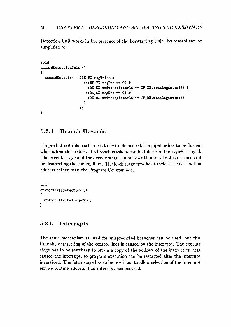
50 CHAPTER 5. DESCRIBING AND SIMULATING THE HARDWARE
Detection Unit works in the presence of the Forwarding Unit. Its control can besimplified to:
voidhazardDetectionUnit (){
hazardDetected = (DE_EX.regWrite t(((DE_EX.regDst == 0) t
(DE_EX.writeRegisterRd == IF_DE.readRegister1»((DE_EX.regDst == 0) t
(DE_EX.writeRegisterRd == IF_DE.readRegister1»)
) ;}
5.3.4 Branch Hazards
If a predict-not-taken scheme is to be implemented, the pipeline has to be flushedwhen a branch is taken. If a branch is taken, can be told from the st pcSrc signal.The execute stage and the decode stage can be rewritten to take this into accountby deasserting the control lines. The fetch stage now has to select the destinationaddress rather than the Program Counter + 4.
voidbranchTakenDetection (){
branchDetected =pcSrc;}
5.3.5 Interrupts
The same mechanism as used for mispredicted branches can be used, but thistime the deasserting of the control lines is caused by the interrupt. The executestage has to be rewritten to retain a copy of the address of the instruction thatcaused the interrupt, so program execution can be restarted after the interruptis serviced. The fetch stage has to be rewritten to allow selection of the interruptservice routine address if an interrupt has occured.

5.3. THE IMPROVED MODEL
voidinterruptOccurredDetection (){
interruptOccurred = 'set if an interrupt occurred';}
5.3.6 Putting it All Together
51
The simulator framework now consists of a loop to call the pipe stages in reverseorder, followed by a call to the control units to determine the state of the controllines. The control lines are variables local to oneCycle. They are determined atthe end of cycle n and used by the stages during cycle n + 1.
voidoneCycleO{
n = I - 1;
while (n >= 0) {'call stage n';n = n - 1;
}
hazardDetectionUnit();forwardingUnit();brancTakenDetection();interruptOccuredDetection();
}

Chapter 6
The Language
"Language is only the instrument of science,and words are but the signs of ideas."Samuel Johnson.
In the previous chapter it is shown that it is possible to describe the behavior ofa pipelined implementation by describing the behavior of the pipe stages andvarious control units. The description language used was a C-like language.SIMDES bears a strong resemblance in functionality to C. This chapter presentsthe language constructs which have to be added to SIMDES so that the behaviorof a parallel implementation can be described.
The complete SIMDES grammar and production rules can be found in AppendixA. In SIMDES the behavior of the instructions is described in order to be able tosimulate the behavior of the processor. In PSIMDES this is completely replacedby the behavioral description of the implementation. This means that there areelements in SIMDES that do not have to be included in PSIMDES. A prime example is the instruction...block, since in PSIMDES the behavior of the instructionsis indirectly specified by describing the behavior of the hardware.
When designing SIMDES a modular approach was chosen. In SIMDES a description consists of modules or blocks. This facilitates expansion of the language withnew constructs. Blocks not needed by one particular tool can be discarded by itsparser. This chapter only deals with what has to be added to the language, notwith what can be omitted. The extensions to SIMDES are given in the same style
53

54 CHAPTER 6. THE LANGUAGE
and notation as the SIMDES grammar and production rules in the appendix.
6.1 Pipeline Registers
As shown in Chapter 5 the pipeline registers are kept identical for all stages inorder to facilitate simulation.
pipe_register
controllinescontrolline_declarationscontrolline_declarationscontrolline_declarationcontrolline_declaration
I[ 'piperegister' registerscontrollines ] I
I ['controllines' controlline_declarations]1controlline_declarationcontrolline_declaration ; controlline_declarations
identifiers designator1 { Int }
The production rules for registers remain unchanged. The above syntax declaresa pipeline register containing registers and control lines for the main control unit.These registers and control lines are a union (in the mathematical sense of theword, not a C union) of all information that could possibly be needed in thecommunication between any two pipe stages, as explained in Chapter 5.
For the example architecture of the previous chapter the declaration of thepipeline register could look like this:
I [ piperegister :I [ registers : programCounter{32};
instruction{32};readData1{S}; # read register numberreadData2{S};signExtended{32};writeRegisterRt{S};writeRegisterRd{S};writeRegister{S};addResult{32};zero{1};aluResult{32};readData{32};writeData{32}; ] I

6.2. PIPE STAGES
memRead{1};memWrite{1};branch{1};pcSrc{1};memtoReg{t}; ] I
]1
6.2 Pipe Stages
55
The block pipestages contains the behavioral descriptions of the pipestages. Thestages are described by means of SIMDES functions without any parameters andwith return type void. The number of stages is arbitrary. The order in whichthe stages are defined is the order in which the stages are called. If there are Nstages, the first function describes stage N, the second describes stage N -1, etc.Finally, the last function describes stage 1.
pipe_stagesstagesstagesstage
1['pipestages' stages] 1
stage stages
function
Each stage has a pipeline register associated with it. Stage n can read a fieldfrom the pipeline register of the previous pipeline stage (n - 1) by reading thevalue of in. fieldlfame. It can write to a field of pipeline register n by assigning avalue to out. f ieldllame.
6.2.1 Main Control
The main control unit is always in the decode stage. It generates the control linesfor the pipeline register of the decode stage, according to the type of instructionbeing processed. Its behavior can be expressed algorithmically. The algorithmspecified in the block main_control modifies variables that represent the controllines. These can be local to the decode stage. After the main control is processed,the code of the decode stage explicitly writes the control lines into the pipelineregister.
I ['maincontrol ' statement_list] I

56 CHAPTER 6. THE LANGUAGE
6.3 Control Units
The control units that deal with the problems specific to the pipelined implementation are defined in the block controlunits. Just like the pipestages, they arefunctions without parameters and with return type void.
control_unitsunitsunitsunit
6.4 One Cycle
I ['controlunits' units] Iunit units
function
The block onecycle forms the simulator framework. Together with the block thatdefines the pipeline registers, it replaces the description of the behavior of theinstructions for the sequential implementation.
I ['onecycle' pipe_stages control_units] I
Communication between the pipe stages takes place through the pipeline registers. As described earlier, a stage can only read from the pipeline register of itspredecessor and write in its own pipeline register. Only the control units haveaccess to all pipeline registers.

Chapter 7
Conclusions
"It is difficult to say what is impossible,for the dream of yesterday is the hope of todayand the reality of tomorrow."Robert H. Goddard
7.1 Effect on the Model
The assumption that pipelined architectures can be described and simulated atvirtually the same level of abstraction as sequential architectures by 'adding a
little bit of information about the implementation' is misguided. Description of aparallel architecture's behavior requires an approach that is completely differentfrom the one used for sequential architectures. A description of the behavior ofthe implementation rather than a description of the behavior of the instructions.Since the design of pipelined architectures is very complicated, it is very hard todevise a generic model at Level 1 which covers all the possible strategies to copewith all the complications involved.
The first section of Chapter 3 might give the reader the impression that pipelinedarchitectures are just as easy to model at Levell of SIMPROACH as sequentialarchitectures. But the other sections reveal the complications that are involvedin pipeline design. Chapter 4 offers a description of the hardware required tosolve the most trivial problems in pipeline design for a very limited subset of
57

58 CHAPTER 7. CONCLUSIONS
an instruction set. In Chapter 5 these solutions are put together in a model.Chapter 6 gives a language for describing an implementation in this model.
A possible way to cope with the complications could be to ignore the implementation and use a simplified model, but as shown in chapter 3, omitting certainimplementation details can lead to a severe degradation of the quality of thesimulation results. Simulations are intended to gather performance figures. Bydepriving a designer of the means to implement a high performance pipeline inthe simulation environment, the results are handicapped from the start. Depending on the degree of simplification, the performance figures can even be computedwithout simulation at all.
7.2 Effect on the Language
The only solution that is guaranteed to work is to allow for as much implementation detail as necessary to implement all the known strategies that are usedto create high performance pipelined architectures. This can only be done wellat Level 2 of SIMPROACH. Covering all the complications involved in pipelinedesign requires such an amount of detail, that the only way to do it right seems tobe to use an existing (hardware description) language and spend research time onhow to model pipelines in an existing language rather than spend it on designing
a new language to describe hardware.
Arguments in favor of this statement can be found in the literature. Furber[Fur89] reports that Modula was used to simulate the ARM completely before itwas implemented. References go back as early as Blaauw [Bla76], who states that"APL is particularly suited [... ] since it allows expression at the high architecturallevel, at the lowest implementation level, and at all levels between." Sayingthis, he stresses the importance of letting the designer determine the model andthe level of abstraction himself.
One of the original design goals was to get as much information as possible aboutthe functional behavior of the architecture out of the existing SIMDES description.The thought behind it was that once a designer takes the decision-based onthe results of a functional simulation by a simulator generated by SIMGEN-tocontinue with a design, he could add information for parallel simulation to thedescription. Next, simulation on a simulator generated by PSIMGEN would yieldinformation about the parallel execution of instructions.

7.3. RECOMMENDATIONS 59
Unfortunately, this requirement cannot be met. Only the description of the instruction types and their syllables can be reused. The description of the behaviorof the instructions-accounting for over 95% of the information in a SIMDES
file--must replaced.
A description of the pipestages and the control takes its place. In the suggesteddescription language for pipelined architectures, the description of the pipestagesand the control implicitly describes the behavior of the instructions.
The effect of extending the Levell simulator generator for pipelined architectures on the description language SIMDES is dramatic. The language turns intoa hardware description language. As shown in Chapter 6, adding constructs todescribe the pipe stages and the control to the description language makes thelanguage more complicated. Add to this the fact that one year after the completion of SIMGEN no one has yet succeeded in completing the description of apresent-day processor in SIMDES and it becomes clear that trying to model apipelined processor at Levell might not be such a good idea.
7.3 Recommendations
The basic idea behind SIMPROACH is good. It covers the transformation of anidea for an architecture into a logical circuit diagram by building a sequence ofsuccessively more detailed models.
To be able to model pipelined architectures, the required amount of informationabout the implementation is so large, that it becomes attractive to describe thearchitecture in a hardware description language like VHDL. By taking advantageof VHDL's behavioral code, it is possible to simulate at the register transferlevel [Jen91].
One caveat here is that VHDL is suitable for event-driven simulation. A pipelinedarchitecture is basically a synchronous system. The dynamic scheduling of themodel components which VHDL performs during simulation is not necessary.The overhead for managing the event queue and dispatching the models leads totime consuming compilation simulation runs.
The fact that there are no general systems available for the simulation of pipelinedarchitectures might be explained by the fact that in order to fully describe the ar-

60 CHAPTER 7. CONCLUSIONS
chitecture and to get a realistic impression of the performance of the architectureit is necessary to be able to describe the pipeline strategy in full detail. Usuallythis is done in a general purpose language, for example C. The cycle level MIPSR2000 simulator 'cycle level SPIM', developed at the University of Wisconsin, isa good example[Lar93, Rog93].
Cycle level SPIM uses many of the ideas found in this report, for example thereverse order evaluation of the pipe stages. The author had the advantage ofhaving the full power of C available to express the solutions to the complicationsof implementing the MIPS R2000 pipeline. It seems to be a good idea to explorethe possibilities of decribing pipelined architectures in a general purpose languageand try to find guidelines for such simulators. The resulting type of simulatorwill have a significant advantage over simulation using VHDL in both compilationtime as well as execution time.
Concentration should be shifted to the study of techniques and libraries for simulating, using a language such as C or C++. A C++ class library could be theideal method for implementing the flexibility, efficiency, and reusability that isneeded for SIMPROACH.
Acknowledgements
I wrote this report without any help from anyone, and if you believe that, my friends andI have the ultimate architecture simulation tools we'd like to sell to you.
Carel Braam, Luc Cluitmans, Pieter Schoenmakers, Bruce Watson, Willem Jan Withagen.
The report is dedicated to my grandfather, Johan Waucomont (t 16 Oct 1983), who taught me
to never leave a job unfinished.

Appendix A
SimDes Grammar andProduction rules
The SIMDES grammar can be characterized using the following items:
1. Start symbol
2. Non-terminals
3. Terminals
4. Production rules
1. Start symbol
Start symbol: description
2. Non-terminals
Non-terminals in order of occurrence:
descriptionresourcesmemorypcregistersregister_declarationsregister_declarationports
61

62 APPENDIX A. SIMDES GRAMMAR AND PRODUCTION RULES
port_declarationsport_declarationaliasesalias_declarationsalias_declarationstatisticsstatistic_declarationsstatistic_declarationidentifiersrest_identifiersdesignator1initial_valuesinteger_listrest_integer_listimplementationsrest_implementationslocal_resourcesfetchbufferfunction_blockfunctionsfunctionparametersrest_parametersparameterreturn_typefetch_blockinstruction_blockinstructionsinstructionopcoderest_opcodeoperandrest_operandtraphandler_blocklocalslocalstatement_listblockstatementalternativesfunction_argumentsrest_argumentsdesignator2

63
3. Terminals
Terminal symbols which occur in the production rules are handed to theparser by the scanner. These symbols are placed within quotes, except forthe Ident and Int symbols.
Terminals:
descriptionresourcesmemoryPCportsregistersaliasesimplementationfunctionsinstructionstraphandlerstatisticsfetchfetchbuffer
ifthenelsefortodowntodo'il'hilerepeatuntilcasedefaultreturnvoid
IdentInt

65
4. Production rules
The SIMDES grammar is a context-free grammar. A non-terminal is replaced by (n)one or more non-terminals or terminals. All rules consist ofa non-terminal on the left-hand side of the colon and an optional nonterminal/terminal mix on the right-hand side.
non-terminal
Production rules:
: (non-terminal I terminal)*
/* global description production rules */
descriptiondescription I[ 'description' Ident resources
statistics implementations] I
/* production rules resources */
resources I[ 'resources' memoryregistersaliases
pcports
]1
memory
pc
registersregistersregister_declarationsregister_declarationsregister_declarationregister_declaration
portsportsport_declarationsport_declarationsport_declarationport_declaration
aliasesaliasesalias_declarations
I[ 'memory' : Ident [ Int ] { Int } ] I
I [ 'PC' : Ident { Int } = { Int } ]1
I[ 'registers' : register_declarations]1register_declarationregister_declaration ; register_declarations
identifiers designator1 { Int } initial_values
1 [ 'ports' : port_declarations] 1
port_declarationport_declaration ; port_declarations
identifiers designator1 { Int }
I [ 'aliases' : alias_declarations] 1
alias_declaration

66 APPENDIX A. SIMDES GRAMMAR AND PRODUCTION RULES
alias_declarationsalias_declarationalias_declarationalias_declaration
alias_declaration ; alias_declarations
Ident = Ident designator1 { Int }Ident = Ident designator1 { Int Int }
Ident rest_identifiersidentifiersrest_identifiersrest_identifiers . . Ident rest_identifiers
designator1designator1
initial_valuesinitial_values
integer_listrest_integer_listrest_integer_list
[ Int ] designator1
= { integer_list}
/* statistics global to description */
statisticsstatisticsstatistic_declarationsstatistic_declarationsstatistic_declarationstatistic_declaration
I[ 'statistics' : statistic_declarations] Istatistic_declarationstatistic_declaration ; statistic_declarations
identifiers designator1 { Int }
/* implementation block production rules */
implementationsrest_implementationsrest_implementations
implementation
implementation rest_implementations
implementation rest_implementations
I [ 'implementation' : Identlocal_resourcesstatisticsfunction_blockfetch_blockinstruction_blocktraphandler_block :I I

/* resources local to implementation */
67
I [ 'resources' fetchbuffer registersaliases ]1
fetchbuffer I [ 'fetchbuffer' : Ident [ Int] { Int }]I
/* functions local to implementation */
function_blockfunction_block I [ 'functions' funct ions ] I
functionsfunctionsfunction
parametersparametersrest_parametersrest_parametersparameter
return_typereturn_type
function functionsIdent ( parameters ) : return_type
{ locals I statement_list }
parameter rest_parameters
, parameter rest_parametersidentifiers { Int }
{ Int }void
/* fetch_block local to implementation */
I [ 'fetch' { locals I statement_list}]1
/* instructions local to implementation */
instruction_blockinstructionsinstructionsinstruction
instruction
I [ 'instructions' : instructions] I
instruction instructionsIdent ( opcode I operand
{ locals I statement_list }Ident ( opcode )
{ locals I statement_list }

68 APPENDIX A. SIMDES GRAMMAR AND PRODUCTION RULES
opcoderest_opcoderest_opcode
Int rest_opcode
, Int rest_opcode
Ident { Int } rest_operandIdent { Int .. Int } rest_operand
operandoperandoperandrest_operandrest_operandrest_operand
. , Ident { Int } rest_operandIdent { Int .. Int } rest_operand
1* traphandler local to implementation *1
traphandler_blocktraphandler_blocktraphandler_block
I [ 'traphandler' : ]1I[ 'traphandler' :
{locals I statement_list} ]1
1* locals used to declare locals preceding statement blocks *1
localslocalslocallocal
local localslocal
identifiers designator1 { Int }
1* From statement_list to statement *1
statement_liststatement_list
blockblock
statementstatementstatementstatement
statement
block statement_listblock
{ statement_list }statement
'if' expression 'then' block'if' expression 'then' block 'else' block'for' Ident designator2 = expression
'to' expression 'do' block'for' Ident designator2 =expression
'downto' expression 'do' block

statementstatementstatement
statementstatementstatementstatementstatementstatementstatementstatementstatementstatementstatementstatementstatementstatementstatementstatement
'vhile' expression 'do' block'repeat block 'until' expression'case' expression
{alternatives 'default''return''return' ( expression)Ident ( tunction_arguments )var = expressionvar *= expressionvar /= expressionvar r,= expressionvar += expressionvar -= expressionvar t= expressionvar -= expressionvar 1= expressionvar «= expressionvar »= expressionvar ++var
block }
69
alternativesalternatives Int block alternatives
tunction_argumentstunction_argumentsrest_argumentsrest_arguments
designator2designator2
varvarvar
expression rest_arguments
• expression rest_arguments
[ expression ] designator2
Ident designator2Ident designator2 { expression}Ident designator2 {expression expression }
/* expressions used in statements */
expressionexpressionexpressionexpression
( expression )IntIdent designator2Ident ( tunction_arguments )

70 APPENDIX A. SIMDES GRAMMAR AND PRODUCTION RULES
1* ternary operator { slice } *1
expression
1* binary operators *1
expression { expression .. expression}
expressionexpressionexpressionexpressionexpressionexpressionexpressionexpressionexpressionexpressionexpressionexpressionexpressionexpressionexpressionexpression
1* unary operator *1
expression
expression *expression Iexpression Yo
expression +expression expression I;
expression ~
expression Iexpression ==expression !=expression <expression >expression <=expression >=expression «expression »
expression
expressionexpressionexpressionexpressionexpressionexpressionexpressionexpressionexpressionexpressionexpressionexpressionexpressionexpressionexpressionexpression

Bibliography
[BCFZ89] B. Bray, K. Cuderman, M. Flynn, and A. Zimmerman. The computerarchitect's workbench. In G. X. Ritter, editor, Proceedings of the IFIP11th World Computer Congress (San Fransisco), pages 509-514. IFIP,Elsevier Science Publishers B.V., 1989.
[Bla76] Gerrit A. Blaauw. Digital System Implementation. Prentice-Hall, Englewood Cliffs, New Jersey, 1976.
[Cor81.] P. Corcoran. Simulator generator system. Proceedings of the IEEE,128(2):61-63, March 1981.
IFur89] Stephen B. Furber. VLSI RISC Architecture and Organization. MarcelDekker, Inc., New York, 1989.
[Hon93] Gaston F. J. A. Honings. Describing an 80386 using PASS. ReportEB436, Eindhoven University of Technology, 1993.
IHP90] John 1. Hennessy and David A. Patterson. Computer Architecture:A Quantitative Approach. Morgan Kauffmann Publishers, Inc., SanMateo, California, 1990.
[HP93] John 1. Hennessy and David A. Patterson. Computer Organization &Design: The Hardware/Software Interface. Morgan Kauffmann Publishers, Inc., San Mateo, California, 1993.
[Jen91] Glen Jennings. Approaches to Register Transfer Modeling of VLSISystems. PhD thesis, Lund University, Sweden, February 1991.
{KR78] Brian W. Kernighan and Dennis M. Ritchie. The C programming Language. Prentice-Hall, Englewood Cliffs, New Jersey, second edition,1978.
71

72 BIBLIOGRAPHY
[KT87] Kovvali S. Kumar and James H. Tracey. Modeling and description ofprocessor-based systems with DTMSII. IEEE Transactions on Computer Aided Design, CAD-6(1):116-127, January 1987.
[Lar93] James R. Larus. SPIM S20: A lvfIPS R2000 Simulator. anonymousftp: cs.wisc.edu, University of Wisconsin-Madison, 1993.
[MJ76] Robert A. Mueller and Gearold R. Johnson. A generator for microprocessor assemblers and simulators. Proceedings of the IEEE, 64(6):921931, June 1976.
[Mu190] J. M. Mulder. The computer architect's workbench. In COMPEURO'90, Proceedings of the 1990 IEEE International Conference on Computer Systems (3 Software Engineering (Tel-Aviv, Israel, 8-10 May
1990), pages 524-525, Los Alamitos, CA, USA, 1990. IEEE ComputerSociety Press.
[Rog93] Anne Rogers. Cycle Level SPIM. anonymous ftp: cs.wisc.edu, Princeton University, 1993.
[Sme91] Jean-Paul C. F. H. Smeets. High Performance Implementation of theC-processor. Report AIO-EB013, Eindhoven University of Technology,1991.
[Tak92] Rob Takken. Sequential instruction set generator. Master's thesis,Eindhoven University of Technology, October 1992.
[Wi169] M. V. Wilkes. The growth of interest in microprogramming: A literature survey. Computing Surveys, 1(3):139-145, September 1969.