Eindhoven University of Technology MASTER · PDF fileCommercially available multirotor...
78
Eindhoven University of Technology MASTER Development of a dynamic flying digital display based on autonomous swarm of UAVs Algan, G. Award date: 2014 Disclaimer This document contains a student thesis (bachelor's or master's), as authored by a student at Eindhoven University of Technology. Student theses are made available in the TU/e repository upon obtaining the required degree. The grade received is not published on the document as presented in the repository. The required complexity or quality of research of student theses may vary by program, and the required minimum study period may vary in duration. General rights Copyright and moral rights for the publications made accessible in the public portal are retained by the authors and/or other copyright owners and it is a condition of accessing publications that users recognise and abide by the legal requirements associated with these rights. • Users may download and print one copy of any publication from the public portal for the purpose of private study or research. • You may not further distribute the material or use it for any profit-making activity or commercial gain Take down policy If you believe that this document breaches copyright please contact us providing details, and we will remove access to the work immediately and investigate your claim. Download date: 25. May. 2018
Transcript of Eindhoven University of Technology MASTER · PDF fileCommercially available multirotor...

Eindhoven University of Technology
MASTER
Development of a dynamic flying digital display based on autonomous swarm of UAVs
Algan, G.
Award date:2014
DisclaimerThis document contains a student thesis (bachelor's or master's), as authored by a student at Eindhoven University of Technology. Studenttheses are made available in the TU/e repository upon obtaining the required degree. The grade received is not published on the documentas presented in the repository. The required complexity or quality of research of student theses may vary by program, and the requiredminimum study period may vary in duration.
General rightsCopyright and moral rights for the publications made accessible in the public portal are retained by the authors and/or other copyright ownersand it is a condition of accessing publications that users recognise and abide by the legal requirements associated with these rights.
• Users may download and print one copy of any publication from the public portal for the purpose of private study or research. • You may not further distribute the material or use it for any profit-making activity or commercial gain
Take down policyIf you believe that this document breaches copyright please contact us providing details, and we will remove access to the work immediatelyand investigate your claim.
Download date: 25. May. 2018
Department of Electrical Engineering
Philips Research Lighting Control Systems
Master thesis: Development of a dynamic flying
digital display based on autonomous swarm of UAVs
Author: Görkem Algan
TU/e supervisor: Philips supervisors: Ass. Prof. Dr. Dip Goswami Alan Pestrin
Dr. Oscar Garcia Morchon
Eindhoven, August 2014

I dedicate this thesis to my family who have always supported me. Thank you Tevfik & Fatoş Algan.
ii | P a g e
Abstract Multirotor systems are aerial vehicles that have several propelled rotors. These kinds of flying platforms are able to fly in all three different axes as well as hover in a specific location. Although in the past these devices were mainly interested by defense industry, over the recent years popularity of multirotor platforms has increased enormously in civil industry as well due to their great maneuver capacity, small size, simple architecture and stability. With this various ad-vantages over other types of unmanned aerial vehicles, multirotors are currently used in different markets such as security, photography, delivery, filming etc.
The goal of this master thesis is the development of a system based on a swarm of multirotor platforms, to create a 3-dimensional digital display in the air. Each multirotor platform, equipped with necessary hardware and software extensions, creates a visible node in the air and its motion is controlled by a central processor unit to generate desired visual content.
There are several challenges to be addressed to achieve this goal. Firstly, a route for each flying device needs to be created autonomously to form the display in the air. Secondly, an efficient algorithm is required to establish communication within the multirotors in real time and intervene with the process in case of emergency (e.g. chance of collision). Thirdly, the standard hardware of the flying platform has to be extended with additional components in order to create visible nodes in the air. Finally, a graphical user interface has to be developed in order to provide the control of the system to users and to allow them to create visual contents to be shown in the air.
Commercially available multirotor platforms have been analyzed and Mikrokopter Quadro XL has been chosen as the flying platform for this project. Mikrokopter hardware has been extended with additional components to create visible nodes in the air. Its firmware has been modified to im-prove the system behavior and enable central processing unit to have full control of the naviga-tion of the device. An algorithm based on Eulerian Path theory has been developed to create GPS waypoint routes for flying devices.
As a result of this master thesis work, the first prototype of a dynamic flying digital display is developed. In order to achieve that, a flying display system with ability to display basic shapes that consists of two UAVs is designed and implemented. With this work, feasibility of such a digital display consisting of a swarm of multirotors is proven to be possible. Experimental tests and observations have shown that extension of the hardware of the flying platform with appropri-ate components makes it possible to create a visible node in the air. Also it has been shown that autonomous control of multiple UAVs by a central processing unit is possible. Another important result is the collaboration of multiple flying devices rather than a single one results in better quality in the display while increasing the complexity of the system.
iii | P a g e
Preface In addition to my Master of Science degree at the Eindhoven University of Technology, this master thesis is the result of my internship carried out at the Philips Research Lab. of Eindhoven, the Netherlands. I would like to thank everybody at TU/e and Philips Research Lab. who helped me during this period of time. There are several people in particular to whom I wish to express my sincere gratitude.
I would like to thank my internship supervisors Alan Pestrin and Oscar Garcia Morchon for giving me the opportunity to have this unique experience and for the trust and guidance given during all my internship period. It has been a privilege to work with them and I am thankful for their support and teaching during my thesis work.
I want to express my sincere appreciation to my University supervisor Dip Goswami, assistant professor of Electronic System at the Eindhoven University of Technology. I would like to thank him for his trust and guidance during my whole master thesis.
I would also like to thank EIT ICT Labs. Masterschool society for wonderful two years of master’s study. It has been a privilege to be part of this master track and I am grateful for all memorable friendships and unforgettable memories.
Lastly, but most importantly, I would like thank my family who have supported me for my whole studies. They deserve as much credit as I do on this thesis, if not more so.
Görkem Algan Eindhoven, August 2014
iv | P a g e
Contents 1. Introduction .......................................................................................................................... 9
1.1. Motivation .................................................................................................................... 9 1.2. Concept of the project ................................................................................................. 9 1.3. Application requirements ........................................................................................... 10 1.4. Related work .............................................................................................................. 11 1.5. Outline of the thesis ................................................................................................... 11
2. Basic concepts .................................................................................................................. 12
2.1. Multirotor concept ...................................................................................................... 12 2.2. Quadrotor modelling .................................................................................................. 13 2.3. Mikrokopter ................................................................................................................ 14
3. System design ................................................................................................................... 16
3.1. System description .................................................................................................... 16 3.1.1. Basic concepts and functionalities................................................................ 16
3.2. Overall design of the flying lights and control unit ..................................................... 17 3.2.1. Design options .............................................................................................. 17 3.2.2. Overall envisioned system ............................................................................ 21
3.3. Overal system operation and control strategy ........................................................... 22 3.4. Management functionalities ....................................................................................... 23
3.4.1. System execution functionalities .................................................................. 23 3.4.2. System monitoring functionalities ................................................................. 24 3.4.3. System termination functionalities ................................................................ 25 3.4.4. User controllable functionalities .................................................................... 27
3.5. Path finder algorithm ................................................................................................. 27 3.5.1. Analyze ......................................................................................................... 28 3.5.2. Path computation .......................................................................................... 29 3.5.3. Data transformation ...................................................................................... 34 3.5.4. Potential improvements ................................................................................ 34
3.6. Graphical user interface ............................................................................................ 34 3.6.1. Content designer window ............................................................................. 35 3.6.2. Control window ............................................................................................. 37
4. System implementation .................................................................................................... 39
4.1. Hardware implementation ......................................................................................... 39 4.1.1. Multirotor ....................................................................................................... 40 4.1.2. Remote controller ......................................................................................... 40 4.1.3. Lighting system ............................................................................................. 41 4.1.4. Control station............................................................................................... 42
v | P a g e

4.1.5. Overall system .............................................................................................. 42 4.2. Software implementation ........................................................................................... 44
4.2.1. Control station............................................................................................... 44 4.2.2. Mikrokopter firmware .................................................................................... 45
4.3. Communication protocol implementation .................................................................. 46 4.3.1. Unidirectional RC flight control ..................................................................... 47 4.3.2. Bidirectional system control .......................................................................... 48
4.4. Graphical user interface ............................................................................................ 49 4.4.1. Content designer window ............................................................................. 50 4.4.2. Control window ............................................................................................. 52
5. Test and evaluation ........................................................................................................... 53
5.1. Path designing ........................................................................................................... 53 5.1.1. Distance of interval ....................................................................................... 53 5.1.2. Speed ........................................................................................................... 54 5.1.3. Positioning .................................................................................................... 55
5.2. Control loop ............................................................................................................... 56 5.3. Lighting system .......................................................................................................... 57 5.4. Display with long exposure time ................................................................................ 57
6. Conclusion and future work ............................................................................................. 60
A. Hardware ............................................................................................................................ 62
B. Software .............................................................................................................................. 70
Bibliography ............................................................................................................................... 76
vi | P a g e
List of figures Figure 2.1: Multirotor types ............................................................................................................ 12 Figure 2.2: Quadrotor rotor rotation directions .............................................................................. 13 Figure 2.3: Quadrotor movements ................................................................................................ 14 Figure 2.4: Mikrokopter Quadro XL ............................................................................................... 15 Figure 3.1: System basic components and their communication .................................................. 16 Figure 3.2: Demonstration for creating a rectangle shape in the air with laser beams ................. 18 Figure 3.3: System operation flowchart ......................................................................................... 22 Figure 3.4: Communication between components ........................................................................ 23 Figure 3.5: Process initialization operation flowchart .................................................................... 24 Figure 3.6: Battery check and system evaluation flowchart .......................................................... 25 Figure 3.7: Come home function ................................................................................................... 26 Figure 3.8: Emergency landing function ........................................................................................ 26 Figure 3.9: Evacuate system function flowchart ............................................................................ 27 Figure 3.10: Path finder algorithm flowchart ................................................................................. 28 Figure 3.11: Creating curved edges with straight lines ................................................................. 28 Figure 3.12: Design on grid of points ............................................................................................ 29 Figure 3.13: Path finding algorithm options ................................................................................... 30 Figure 3.14: Transforming a graph to Eulerian Cycle ................................................................... 31 Figure 3.15: Transforming graph to Eulerian cycle in 3D .............................................................. 32 Figure 3.16: Splitting vertex variations .......................................................................................... 32 Figure 3.17: Splitting vertex in 3D matrix ...................................................................................... 33 Figure 3.18: Fleury's algorithm flowchart ...................................................................................... 33 Figure 3.19: Fleury's algorithm ...................................................................................................... 34 Figure 3.20: Creation of the visual content with adding new vertices ........................................... 36 Figure 3.21: Node modify scenario ............................................................................................... 36 Figure 3.22: Content designer tool flowchart ................................................................................ 36 Figure 3.23: Control window design .............................................................................................. 37 Figure 3.24: Go to location operation interface ............................................................................. 38 Figure 4.1: Hardware architecture of the system .......................................................................... 40 Figure 4.2: Flying light component ................................................................................................ 42 Figure 4.3: Light source and smoke generator ............................................................................. 43 Figure 4.4: Control station with two Wi.232 module connected to it ............................................. 44 Figure 4.5: Communication protocol ............................................................................................. 47 Figure 4.6: Graupner MX 20 HoTT remote controller channel configurations .............................. 47 Figure 4.7: Content designer window ............................................................................................ 50 Figure 4.8: Creation of the visual content ..................................................................................... 51 Figure 4.9: Node modifying procedure .......................................................................................... 51 Figure 4.10: Control Window ......................................................................................................... 52 Figure 4.11: Go to location window ............................................................................................... 52 Figure 5.1: Effect of distance on flight time ................................................................................... 54 Figure 5.2: Ideal and actual flight time for speed of 2 [m/s] .......................................................... 54 Figure 5.3: Ideal and actual flight time for speed of 4 [m/s] .......................................................... 55 Figure 5.4: Ideal and actual flight time for speed of 6 [m/s] .......................................................... 55 Figure 5.5: Effect of positioning on flight time ............................................................................... 56 Figure 5.6: Lighting system test .................................................................................................... 57 Figure 5.7: Long exposure time test .............................................................................................. 58 Figure 5.8: Long exposure display with light source ..................................................................... 58 Figure 5.9: Long exposure display with light source and smoke generator .................................. 59 Figure 5.10: Long exposure display to create a letter of "P" ......................................................... 59 Figure A.1: Mikrokopter FlightCtrl board ....................................................................................... 62 Figure A.2: Addition of ACC board to FlightCtrl ............................................................................ 62 Figure A.3: Mikrokopter FlightCtrl connections ............................................................................. 63 Figure A.4: Mikrokopter NaviCtrl board ......................................................................................... 63 Figure A.5: Mikrokopter NaviCtrl connections ............................................................................... 64
vii | P a g e
Figure A.6: Mikrokopter MKGPS board ......................................................................................... 64 Figure A.7: GPS shield for MKGPS............................................................................................... 65 Figure A.8: Mikrokopter power distribution board and electric speed controllers ......................... 65 Figure A.9: Wi.232 V2.0 set .......................................................................................................... 67 Figure A.10: Light control board .................................................................................................... 68 Figure A.11: Tiny FX smoke generator ......................................................................................... 68 Figure A.12: Graupner MX 20 HoTT remote controller and GR 23 receiver ................................ 69 Figure B.1: Class structure of Graph ............................................................................................. 71
List of tables Table 2.1: Comparison of different multirotor platforms ................................................................ 14 Table 3.1: Summary of possible solutions .................................................................................... 20 Table 3.2: Advantages and disadvantages of navigations systems ............................................. 30 Table 4.1: Mikrokopter serial communication protocol data structure........................................... 48 Table 4.2: Used functions for communicating Mikrokopter ........................................................... 49 Table A.1: MK3638 brushless motor and EPP1345 CF propeller technical specifications ........... 66 Table A.2: Hp EliteBook 840 G1 technical specifications ............................................................. 66 Table A.3: Light source battery specifications ............................................................................... 67 Table A.4: Light source battery specifications ............................................................................... 68
viii | P a g e
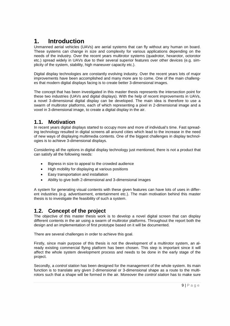
1. Introduction Unmanned aerial vehicles (UAVs) are aerial systems that can fly without any human on board. These systems can change in size and complexity for various applications depending on the needs of the industry. Over the recent years multirotor systems (quadrotor, hexarotor, octorotor etc.) spread widely in UAVs due to their several superior features over other devices (e.g. sim-plicity of the system, stability, high maneuver capacity etc.).
Digital display technologies are constantly evolving industry. Over the recent years lots of major improvements have been accomplished and many more are to come. One of the main challeng-es that modern digital displays facing is to create better 3-dimensional images.
The concept that has been investigated in this master thesis represents the intersection point for these two industries (UAVs and digital displays). With the help of recent improvements in UAVs, a novel 3-dimensional digital display can be developed. The main idea is therefore to use a swarm of multirotor platforms, each of which representing a pixel in 2-dimensional image and a voxel in 3-dimensional image, to create a digital display in the air.
1.1. Motivation In recent years digital displays started to occupy more and more of individual’s time. Fast spread-ing technology resulted in digital screens all around cities which lead to the increase in the need of new ways of displaying multimedia contents. One of the biggest challenges in display technol-ogies is to achieve 3-dimensional displays.
Considering all the options in digital display technology just mentioned, there is not a product that can satisfy all the following needs:
• Bigness in size to appeal to the crowded audience • High mobility for displaying at various positions • Easy transportation and installation • Ability to give both 2-dimensional and 3-dimensional images
A system for generating visual contents with these given features can have lots of uses in differ-ent industries (e.g. advertisement, entertainment etc.). The main motivation behind this master thesis is to investigate the feasibility of such a system.
1.2. Concept of the project The objective of this master thesis work is to develop a novel digital screen that can display different contents in the air using a swarm of multirotor platforms. Throughout the report both the design and an implementation of first prototype based on it will be documented.
There are several challenges in order to achieve this goal.
Firstly, since main purpose of this thesis is not the development of a multirotor system, an al-ready existing commercial flying platform has been chosen. This step is important since it will affect the whole system development process and needs to be done in the early stage of the project.
Secondly, a control station has been designed for the management of the whole system. Its main function is to translate any given 2-dimensional or 3-dimensional shape as a route to the multi-rotors such that a shape will be formed in the air. Moreover the control station has to make sure
9 | P a g e
that system is working properly during whole execution and apply the commands from the user if there is any.
Thirdly, hardware extensions for multirotor flying platform have been selected and added consid-ering the UAV specifications (e.g. payload capacity, balance conditions). This is an important step to maximize the visualization capabilities of the flying platform which has a direct influence on the display quality.
Finally, a graphical user interface has been developed in order to transform multimedia contents into actual images in the air. It should provide necessary tools for user to create a content to be displayed in the air and manage the system operation.
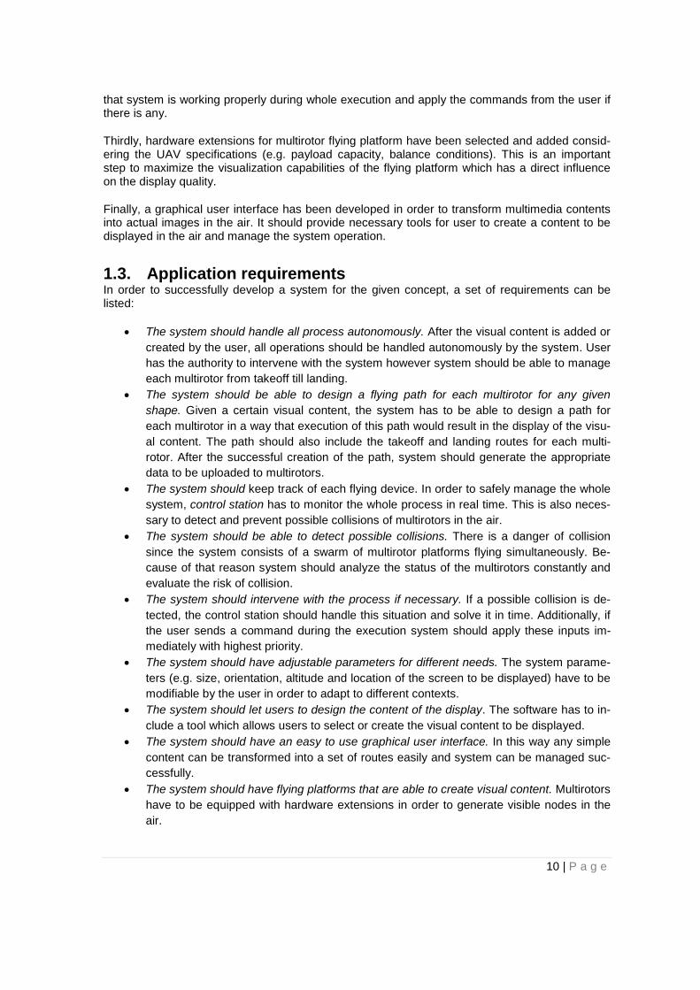
1.3. Application requirements In order to successfully develop a system for the given concept, a set of requirements can be listed:
• The system should handle all process autonomously. After the visual content is added or created by the user, all operations should be handled autonomously by the system. User has the authority to intervene with the system however system should be able to manage each multirotor from takeoff till landing.
• The system should be able to design a flying path for each multirotor for any given shape. Given a certain visual content, the system has to be able to design a path for each multirotor in a way that execution of this path would result in the display of the visu-al content. The path should also include the takeoff and landing routes for each multi-rotor. After the successful creation of the path, system should generate the appropriate data to be uploaded to multirotors.
• The system should keep track of each flying device. In order to safely manage the whole system, control station has to monitor the whole process in real time. This is also neces-sary to detect and prevent possible collisions of multirotors in the air.
• The system should be able to detect possible collisions. There is a danger of collision since the system consists of a swarm of multirotor platforms flying simultaneously. Be-cause of that reason system should analyze the status of the multirotors constantly and evaluate the risk of collision.
• The system should intervene with the process if necessary. If a possible collision is de-tected, the control station should handle this situation and solve it in time. Additionally, if the user sends a command during the execution system should apply these inputs im-mediately with highest priority.
• The system should have adjustable parameters for different needs. The system parame-ters (e.g. size, orientation, altitude and location of the screen to be displayed) have to be modifiable by the user in order to adapt to different contexts.
• The system should let users to design the content of the display. The software has to in-clude a tool which allows users to select or create the visual content to be displayed.
• The system should have an easy to use graphical user interface. In this way any simple content can be transformed into a set of routes easily and system can be managed suc-cessfully.
• The system should have flying platforms that are able to create visual content. Multirotors have to be equipped with hardware extensions in order to generate visible nodes in the air.
10 | P a g e
1.4. Related work There are several researches going on for 3-dimensioanal displays. Most significant development can be shown as the laser plasma scanning 3D display from Burton Inc. and Keio University [10]. This system uses laser-plasma technology to generate points in the air to be used as pixels. With the help of this technology simple 3D structures can be constructed in the air. The introduced system has an ability to perform 50.000 points/sec in white color only. Another 3-dimensional display is the Kinetic Sculpture project developed by Art+Com for BMW [11]. 714 metal spheres, hanging from thin steel wires attached to individually-controlled stepper motors and covering the area of six square meters, animate a 3-dimensional display for audience. Ocean of light is anoth-er project that uses hanging LED strips in vertical layers to generate 3-dimensional effects [18]. Lastly, a project is developed by Ars Electronica Futurelab to use multirotors as pixels in the air to create 3-dimensional effects [8]. This project can be considered as the closest approach of this master thesis.
1.5. Outline of the thesis This master thesis consists of six sections. After this introduction section, Section 2 is devoted to the basic concepts related to the work that has been done in this thesis. Section 3 explains the design of the desired system. Section 4 documents the system implementation process. Section 5 discusses the tests and their evaluation about the system performance. Lastly, Section 6 con-cludes the work of this thesis and provides potential future work. At the end, various appendices and references can be found related to the discussions in this report.
11 | P a g e

2. Basic concepts This chapter starts with the introduction of the multirotor concept. After that, quadrotor (a type of multirotor) modelling will be explained. Lastly, the chosen multirotor platform will be documented.
2.1. Multirotor concept Multirotor aerial vehicle term is used for the flying platforms with more than two rotors. These devices are named after the number of their rotors such as quadrotor, hexarotor and octorotor referring to four, six and eight rotor vehicles. Because of the simplicity in the architecture and satisfactory performance, quadrotors are the most popular multirotor vehicles among others.
Figure 2.1: Multirotor types. (a) Mikrokopter Quadro XL (b) Mikrokopter Hexa XL (c) Mikrokopter Octo XL [16]
Multirotor platforms consist of several main parts:
• Frame: A component to hold all system together. It acts as the skeleton to the system. It should be both resistant enough to certain amount of the pressure and light enough to save system from excessive payload.
• Motors and propellers: Directly responsible for the aerodynamic movement of the multi-rotor platform. According to the type of the multirotor platform it can be in different num-bers (4,6 and 8 respectively for quadrotor, hexarotor and octorotor)
• Battery: Energy source for the whole system. LiPo (lithium-polymer) batteries are usually preferred due to their high performance/weight ratio.
• Sensors: Hardware components to provide necessary data about the physical activities of the multirotor platform. Most essential sensors are gyroscope, accelerometer, barome-ter and compass respectively for the measurement of orientation, acceleration, altitude and heading of the multirotor platform. In addition to these sensors GPS receiver can be added to obtain the position information of the multirotor. Beside these sensors additional sensing elements (e.g. temperature sensor, humidity sensor etc.) can be used according to the necessity of the project.
• Motor driver: A component to allocate required current to each rotor. It works as a me-diator between battery and the rotors.
• Electric boards: The brain of the system where all data processing is done and required commands are produced for other hardware components. It receives the data from the sensors to analyze the condition of the multirotor and sends the required commands to motor driver to apply desired movements.
12 | P a g e
2.2. Quadrotor modelling Quadrotor is a term used for multirotor platforms which consists of four propelled rotors with 90 degrees apart from each other. Different combinations in the speed of the rotors enable quad-rotor to perform maneuvers in 3 dimensional axes. These movements are called pitch, roll, heave and yaw.
First quadrotor was designed at 1920s and was utilized as passenger aircraft [22]. However design of the robotic quadrotors starts after 21st century. Design of earliest robotic quadrotors starts around 2005 [20][21]. Since then lots of researches are going on to increase the flying capabilities of these devices [9]. These extensive researches results in a booming industry that generates new uses of these devices every day [1][2][7][15][17].
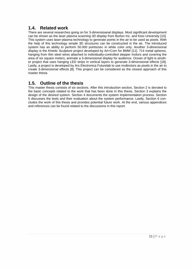
A model for the rotor movement directions is illustrated in the Figure 2.2. There are two different rotation directions for the motors (clockwise and counterclockwise). While the rotors on the y-axis rotates clockwise, the rotors on the x-axis rotates counterclockwise. Reason behind this behavior is to balance the angular momentum of the system. Yaw movement can be controlled by adjust-ing the average speed of clockwise and counterclockwise rotating rotors.
Figure 2.2: Quadrotor rotor rotation directions. T1, T2, T3 and T4 indicates the thrust of the indicated rotor [14]
Heave movement can be controlled with the adjustment of the total thrust of the rotors. While keeping the angular momentum balanced, increasing the total thrust would cause an upward movement in the z-axis and decreasing the total thrust would cause a downward movement in the z-axis.
Pitch and roll movement can be controlled with the adjustment of the rotors in the movement axis. For example, in order to move in the direction of the positive y-axis, T4 should be increased and T1 should be decreased in a way that given equation below is satisfied to keep angular momentum balanced.
T2 + T4 = T1 + T3
Illustration of the rotor speeds for different movements are given in the Figure 2.3.
13 | P a g e
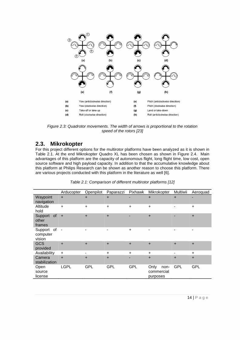
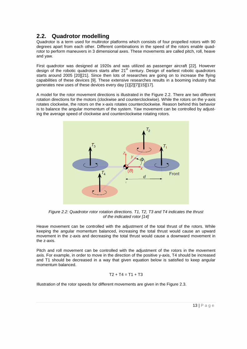
Figure 2.3: Quadrotor movements. The width of arrows is proportional to the rotation speed of the rotors [23]
2.3. Mikrokopter For this project different options for the multirotor platforms have been analyzed as it is shown in Table 2.1. At the end Mikrokopter Quadro XL has been chosen as shown in Figure 2.4. Main advantages of this platform are the capacity of autonomous flight, long flight time, low cost, open source software and high payload capacity. In addition to that the accumulative knowledge about this platform at Philips Research can be shown as another reason to choose this platform. There are various projects conducted with this platform in the literature as well [6].
Table 2.1: Comparison of different multirotor platforms [12]
Arducopter Openpilot Paparazzi Pixhawk Mikrokopter Multiwii Aeroquad Waypoint navigation
+ + + - + + -
Altitude hold
+ + + + + - +
Support of other frames
+ + + - + - +
Support of computer vision
- - - + - - -
GCS provided
+ + + + + + +
Availability + - + + + - + Camera stabilization
+ + + - + + +
Open source license
LGPL GPL GPL GPL Only non-commercial purposes
GPL GPL
14 | P a g e

Figure 2.4: Mikrokopter Quadro XL [16]
Basic electronic boards of the Mikrokopter Quadro XL are listed as below:
• BL-Ctrl: A driver for brushless DC current motors. It allocates the required current com-ing from battery to each rotor according to the commands coming from FlightCtrl.
• MKGPS: The GPS receiver for the Mikrokopter. It has a direct connection to the NaviCtrl where it sends the received GPS data.
• NaviCtrl: The hardware component which is responsible for the autonomous flight activi-ties of the Mikrokopter. Some of these activities can be shown as the waypoint flight, po-sition hold at a certain position and come home location autonomously. It has an inte-grated compass and with the connection of MKGPS it is transformed into a powerful GPS system. It has a connection to the FlightCtrl to send the required data for the manage-ment of the copter.
• FlightCtrl: The brain of the Mikrokopter that is responsible for all essential features of the multirotor (e.g. management of the rotors, altitude control etc.). Mikrokopter is able to endure a proper flight only using this board if GPS coordination is not required.
More detailed information about the hardware components of the Mikrokopter is given in Appen-dix A.
The flying platform length from rotor to rotor excluding propeller length is 56 [cm] and its height is 35 [cm]. The weight of the quadrotor including the LiPo battery is 1490 [g].
15 | P a g e

3. System design This chapter describes the design of the flying display system. Section 3.1 provides a general overview of the concept. Section 3.2 explains basic concepts and functionalities of the system. Section 3.3 documents overall system operation and control strategy. Section 3.4 explains man-agement functionaries that are designed to achieve various operations. Section 3.5 explains the algorithm that is designed for creating routes for multirotors. Lastly, section 3.6 discusses the design of the graphical user interface for the system.
3.1. System description This part of the thesis firstly introduces the basic concepts and functionalities about the system. After that various possible solutions for this project are evaluated. Lastly, the chosen solution with its operation principles is explained.
3.1.1. Basic concepts and functionalities The envisioned system includes three different types of devices:
• Content creation unit: Responsible for the creation and management of (visual) content for the flying display system.
• Flying light: Flying platform with the ability of creating visible content in the air. The sys-tem can include many flying lights.
• Control station: Central node for the system that is responsible of communicating with all of the flying lights during an early configuration phase or also during operation. During configuration, it deploys information related to the content to be played and how it is to be played in a given location. During operation, it receives necessary data related to the sta-tus of the system execution and produces required commands for the management of operations.
Illustration of these components is given in the Figure 3.1.
Figure 3.1: System basic components and their communication
In the above system, we envision several functionalities that are defined as follows:
16 | P a g e

• Content creation: Visual content to be displayed is designed and modified according to the needs.
• GUI: Interface tool provides full control over the system operations and displays status of the execution.
• Flying platform: Flying light component which consists of a flying platform that can carry a lighting system on it.
• Communication: Components (control station and flying lights) exchange data in real time for the maintenance of the system.
• Lighting: Flying light objects create visible nodes or lines in the air for the creation of visual content.
• Positioning: Position of each flying light is determined and used for the execution of the system
• Image animation: Creation of digital screen in the air is achieved with the collaboration of all flying lights. Therefore activities of each flying light is organized.
This master thesis will focus on the design of the overall system but putting emphasis in the design of the lighting, image animation, GUI, content creation and management functionalities. More detailed documentation will be provided in the coming sections.
3.2. Overall design of the flying lights and control unit Creating the above flying display system in the air using a swarm of flying lights can be achieved in various ways. For this project, we firstly consider and evaluate different options for the various functionalities related to the control unit and flying lights. The content creation unit will be dis-cussed in Section 3.6.1.
3.2.1. Design options Flying platform
• Option 1 – Helicopter: Flying platform is the helicopter system. Advantage of helicop-ters is the great maneuver capacity. Disadvantage of helicopters is the high rotational speed of propellers as a result of having small number of rotors. Because of that, in case of collision they create a high damage.
• Option 2 – Multirotor: Flying platform is a multirotor system. Advantages of multirotors are stability, redundancy to motor failures and robustness. Disadvantage can be consid-ered their noisy execution conditions due to the excessive number of rotors.
• Option 3 – Fixed-wing: Flying platform is a fixed wing aerial vehicle platform. Advantage of fixed-wing aerial vehicles is the speed. Disadvantage of these devices is the disability to keep a stationary position in the air and insufficient maneuver capacity.
Control • Option 1 – Distributed: Each flying device can communicate with others and there is no
master – slave communication protocol. This means there is no central node to keep track of the whole system and manage it. Each flying device is able to communicate with others and process its own data. Advantage of this system is the redundancy to node failures because there is no central node that can endanger whole system with failing. On the other hand it is a very complicated solution to implement because each flying de-vice has to perform computations and communicate with others to get information about
17 | P a g e

the system status. Since there is no central master node to take decisions for whole sys-tem, different priority algorithms over cases should be designed.
• Option 2 – Centralized: There is a control station which is responsible for the manage-ment of the whole system [7]. Control station works as a master node to all other slaves which consist of flying devices. Advantage of this system is the simplicity of the structure because all data is gathered in one node and it can be processed here in order to send required commands to other nodes. On the other side weakness of this system is the fact that it is not resilient to the case of failure in master node. However this problem can be solved with taking extra measures for the master node to not fail.
• Option 3 – Mixed: It is a mixture of option 1 and option 2. There is a control station which is responsible for the management of the system. It communicates with all flying devices and processes the data. However flying devices are able to do their own compu-tations as well and can manage their activities. Control unit sends the required com-mands in the beginning of the execution and rest of the operations are handled by the fly-ing devices. Control station interferes with the process if necessary. Advantage of this system is the simplicity of the architecture. Moreover it is more resilient to failure than op-tion 2 since flying devices can still process data without communicating control station.
Lighting • Option 1 – Laser: Each flying device has a laser pointer on it. Laser beam can be point-
ed out to different directions to create a straight line in the air. Advantage of this system is the good visibility of a very straight line. Powerful lasers (more than 15mW) emit visible straight light in the dark areas. Disadvantage of the system is the hard implementation of the stable pointer to target point. If the laser beam doesn’t hit the target point then it will keep going until it hits a target and this will cause distortion in the image. For this reason laser pointing mechanism should be very concise. An illustration of both cases is provid-ed in Figure 3.2.
Figure 3.2: Demonstration for creating a rectangle shape in the air with laser beams (a) Visual content with laser beam hitting the target (b) Visual content with laser
beam missing the target
18 | P a g e

• Option 2 – Light source: Each flying device has a light source on it. Light beam can be pointed out to different directions to create a visible node in the air. Advantage of this system is the simplicity of the architecture. Unlike the laser beam, light beams do not re-quire a target to hit. Because of this reason the system holding the light source does not need to be very concise. Disadvantage of the system is the poor visibility. Light beams do not create a straight line in the air like laser so this will create a node in the air rather than a line. That results in poor visibility in the air.
• Option 3 – Light source with smoke generator: Each flying device has a light source and a smoke generator together. It is similar to the Option 2 however this time smoke is used to increase the visibility of the lighting system. With the smoke particles in the direc-tion of the light beam, a visible straight line can be generated. Advantage of this system is the high visibility. With a powerful light source and an appropriate smoke generator, a visible line can be constructed in the air. Disadvantage of the system is the disability to point light beams in different directions. The airflow around the copter is downwards due to the propeller movements and because of that smoke generator has to point down. This means a visible line can only be constructed in the downward direction according to the multirotor. With extra hardware extensions this can be fixed however that means more complexity and payload.
• Option 4 – Combination of different types of sources: Not all of the flying devices have the same hardware. Some devices have only light source, some devices have only smoke generator and some devices have both of them. Also system is supported with the fixed lights from the ground. Each device has different tasks for example flying devic-es with smoke generator are responsible of keeping the area foggy so that flying devices with light source are more visible. Advantage of this system is the better flying times for the flying devices since not all the hardware is added to single device. Disadvantage is the complexity of the system since every device has to be programmed for a different task.
Positioning • Option 1 – Local: Each flying device has a GPS receiver attached to it and detects its
position via GPS signal. Advantage of this system is the high mobility and easy setup. No additional setup is required to the area where the screen will be formed. Because of that system can be executed anywhere with an availability of a proper GPS signal. Disad-vantage of this system is the low accuracy. Error rate for GPS position accuracy is around two meters however this can change according to the power of GPS signals re-ceived.
• Option 2 – Centralized: Each flying device tracked by the tracking hardware in a fixed location on ground. Most common method is to place several markers and track them by cameras that are placed around the operation area. These kind of systems usually used for acrobatic flight purposes [2][3][13]. Advantage of this configuration is the high accura-cy. These kinds of systems can have an error rate [mm] level [26]. Disadvantage of the system is the necessity for a preliminary setup. Before the execution of the operation the cameras have to be placed in proper positions. This causes a low flexibility in terms of mobility of the system.
Image animation • Option 1 – Stationary: Each flying device has a fixed location in the air. With the help of
content displaying techniques they create visible voxels from their static position. Ad-
19 | P a g e

vantage of this system is the simplicity and the low risk of the system. Since multirotors are not moving, the chance of collision is low. Disadvantage of the system is the low res-olution of the content that is displayed in the air. Since visible nodes are not moving, the distance in between will stay as a dark area.
• Option 2 – Dynamic: Each flying device keeps flying in certain paths during the execu-tion. Each multirotor creates a moving visible node in the air so the image can be formed with the coordinative movements of flying devices. Advantage of this system is the scalability. The content can be displayed with even one flying device; however increasing number of multirotors means better displays. Disadvantage of the system is the higher chance of collision. Since all multirotors keep flying in certain routes, a problem in coor-dination may result in collisions.
Table 3.1 summarizes all considered designed solutions and the advantages and disadvantages of all of them.
Table 3.1: Summary of possible solutions
Category Solution Advantage Disadvantage
Flying platform
Helicopter Maneuverability Not robust, high damage on collision
Multirotor Stability, redundancy to motor failures and robustness
Noisiness
Fixed-wing Speed Disability for stationary flight, less maneuver-ability
Control
Distributed Redundancy to node failures
High complexity for implementation
Centralized Simple architecture Weakness to node failures
Mixed Simple architecture, redundancy to node failures
Less control over the operations
Lighting
Laser High and concise visibility Hard implementation
Light source Simple architecture Poor visibility Light source with smoke generator
Easy implementation and high visibility
Creation of visibility in limited direction
Combination of different types of sources
Rich visibility Complex implementa-tion
Positioning Local Mobility and easy
setup Low accuracy
Centralized High accuracy Requirement of a preliminary setup
Image animation
Stationary Simple architecture and small chance of collision
Poor resolution in the image
Dynamic High resolution of the image and the scala-bility of the system
Higher risk of collision
20 | P a g e
3.2.2. Overall envisioned system As it is given in the previous chapter, there are several different options available for designing the system. Considering the advantages and disadvantages given configuration is chosen;
• Flying platform: Option 2 - Multirotor • Control: Option 3 – Mixed • Lighting: Option 3 – Light source with smoke generator • Positioning: Option 1 – Local • Image animation: Option 2 – Dynamic
Flying platforms consists of multirotor systems.
The system has a control station which acts as a master node. All the multirotors are initialized for operation by the control station. Multirotors perform the operations after that and send data about their condition to the control station periodically. Control station interferes with the proce-dure if there is any necessity.
Each multirotor is equipped with a light source and a smoke generator to create a visual content in the air. These devices are controlled according to the commands received from the control station.
Each multirotor is equipped with a GPS receiver and uses GPS signal data to determine its own position. This data is sent to the control station to be processed.
Multirotors do not endure a stationary flight but they fly in certain paths. These paths are de-signed by the control station and uploaded to each flying device. Control station is also responsi-ble for making sure the correct path is being followed by each flying device.
The overall operation can be divided into three different phases.
Phase 1: Content creation Software provides a tool for user to add or create a visual content to be displayed in the air. Tool should have some basic features such as adding or modifying lines and nodes so that a visual content can be designed. After the visual content design is complete, required paths in the air are generated, translated to appropriate data format and uploaded to the flying devices by the control station.
Phase 2: Parameter adjustment In this phase required parameters for digital screen to be displayed in the air are determined. Software asks user to determine the parameters for the screen which are given below:
• Number of flying devices to be involved in the process • Location and altitude of the screen to be displayed • Vertical and horizontal size of the screen to be displayed
After obtaining these data from the user, system starts the initialization sequence and get ready for the operation.
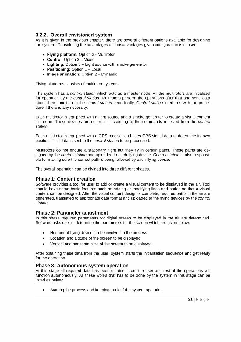
Phase 3: Autonomous system operation At this stage all required data has been obtained from the user and rest of the operations will function autonomously. All these works that has to be done by the system in this stage can be listed as below:
• Starting the process and keeping track of the system operation
21 | P a g e
• Finishing the operation when time comes if there is no errors • Coping with the problem in case of any error • Applying the commands received from the user if there is any
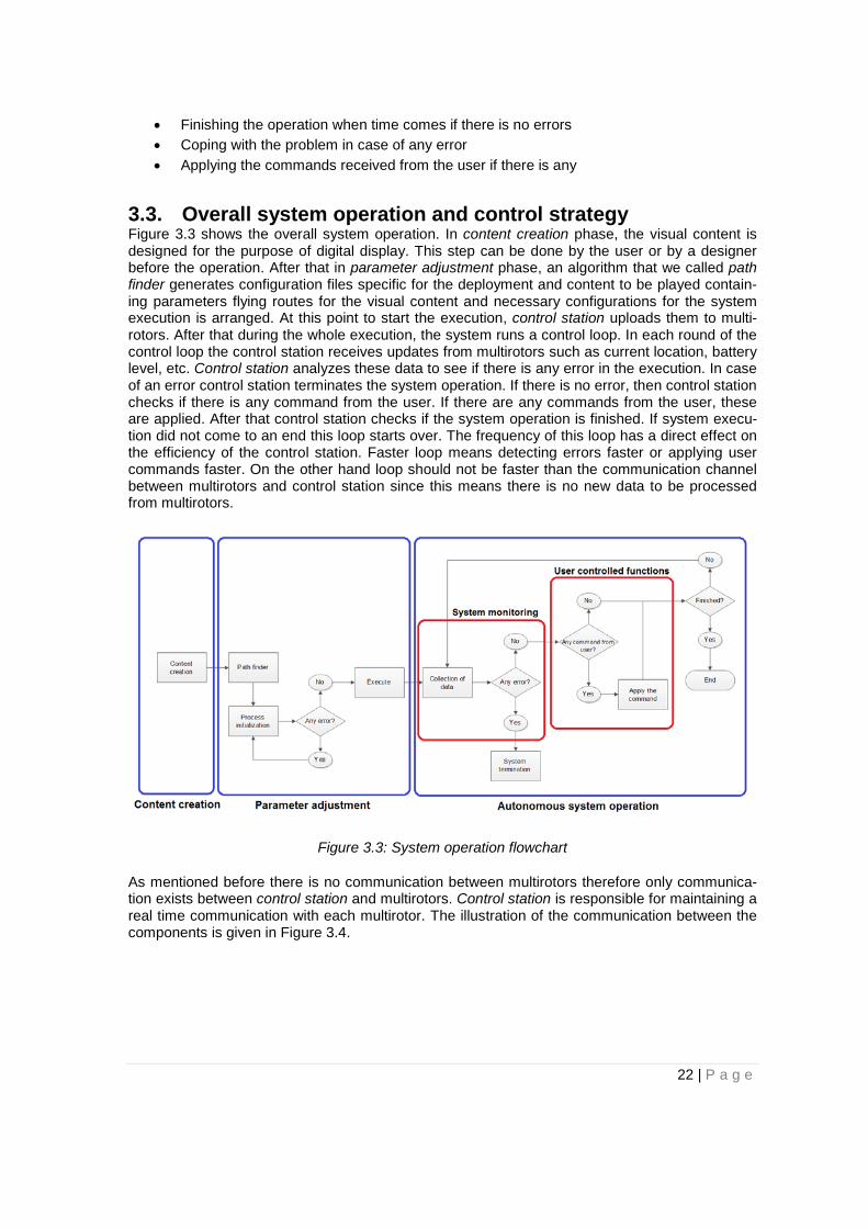
3.3. Overall system operation and control strategy Figure 3.3 shows the overall system operation. In content creation phase, the visual content is designed for the purpose of digital display. This step can be done by the user or by a designer before the operation. After that in parameter adjustment phase, an algorithm that we called path finder generates configuration files specific for the deployment and content to be played contain-ing parameters flying routes for the visual content and necessary configurations for the system execution is arranged. At this point to start the execution, control station uploads them to multi-rotors. After that during the whole execution, the system runs a control loop. In each round of the control loop the control station receives updates from multirotors such as current location, battery level, etc. Control station analyzes these data to see if there is any error in the execution. In case of an error control station terminates the system operation. If there is no error, then control station checks if there is any command from the user. If there are any commands from the user, these are applied. After that control station checks if the system operation is finished. If system execu-tion did not come to an end this loop starts over. The frequency of this loop has a direct effect on the efficiency of the control station. Faster loop means detecting errors faster or applying user commands faster. On the other hand loop should not be faster than the communication channel between multirotors and control station since this means there is no new data to be processed from multirotors.
Figure 3.3: System operation flowchart
As mentioned before there is no communication between multirotors therefore only communica-tion exists between control station and multirotors. Control station is responsible for maintaining a real time communication with each multirotor. The illustration of the communication between the components is given in Figure 3.4.
22 | P a g e
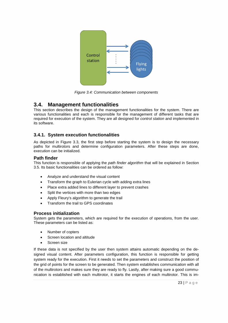
Figure 3.4: Communication between components
3.4. Management functionalities This section describes the design of the management functionalities for the system. There are various functionalities and each is responsible for the management of different tasks that are required for execution of the system. They are all designed for control station and implemented in its software.
3.4.1. System execution functionalities As depicted in Figure 3.3, the first step before starting the system is to design the necessary paths for multirotors and determine configuration parameters. After these steps are done, execution can be initialized.
Path finder This function is responsible of applying the path finder algorithm that will be explained in Section 3.5. Its basic functionalities can be ordered as follow:
• Analyze and understand the visual content • Transform the graph to Eulerian cycle with adding extra lines • Place extra added lines to different layer to prevent crashes • Split the vertices with more than two edges • Apply Fleury’s algorithm to generate the trail • Transform the trail to GPS coordinates
Process initialization System gets the parameters, which are required for the execution of operations, from the user. These parameters can be listed as:
• Number of copters • Screen location and altitude • Screen size
If these data is not specified by the user then system attains automatic depending on the de-signed visual content. After parameters configuration, this function is responsible for getting system ready for the execution. First it needs to set the parameters and construct the position of the grid of points for the screen to be generated. Then system establishes communication with all of the multirotors and makes sure they are ready to fly. Lastly, after making sure a good commu-nication is established with each multirotor, it starts the engines of each multirotor. This is im-
23 | P a g e

portant because home location of the multirotor means where it started the motors. So with this procedure home locations for each multirotor are attained as well. These locations are saved into memory to be used later in the execution. If there is any error this function prevents system to proceed since an error in initialization may cause problems afterwards. The flowchart for the process initialization algorithm is shown in Figure 3.5.
Figure 3.5: Process initialization operation flowchart
Execute This function starts the execution of the system. Its main task is to initialize the takeoff procedure for each multirotor in order. In order to calculate this, it uses the parameters of number of vertices in the visual content and total number of multirotors. Dividing the number of vertices to the num-ber of multirotors gives the value of distance in between each multirotor. For example if there are 2 multirotors in the system and visual content consists of 6 vertices then each multirotor should be 3 vertices away from each other. This means when first multirotor reaches the third vertex, the initialization sequence for the second multirotor can be started. If the number of multirotors is increased then the distance between each of them is decreased which also means the increase in resolution.
3.4.2. System monitoring functionalities As depicted in Figure 3.3, control station should constantly monitor the system operation for any errors in execution.
Battery check System should constantly check the battery level of the multirotors and take initiative if battery level is critically low for any of them. This can be done by getting periodic updates from each multirotors and processing this data by the control station. If there is a low battery indication for any of the multirotor then system should prioritize to safely land this multirotor automatically. There can be two cases here; either multirotor has enough battery to land its home location or not. If it has enough battery then system should land it to the home by calling come home func-tion, but if it does not have enough battery, then the system should land it to the closest position available by calling emergency landing function. Another important manner is that system should consider the positions of the other copters while giving the landing route for low battery multirotor and avoid any possible collisions. Landing procedure requires first the multirotor to descend to a safe altitude where there is no flying activity is going on. In order to prevent collision, there should be no other multirotor beneath the one that is supposed to land. System should check this condi-tion and make sure it is satisfied before it starts the landing procedure. The flowchart for the battery check algorithm is shown in Figure 3.6.
24 | P a g e

Figure 3.6: Battery check and system evaluation flowchart
Position monitoring Volume of Interest (VOI) is determined in process initialization step. This function constantly checks if all the multirotors are inside the VOI. If any of the multirotor is out of the VOI that means system has an error which can damage both system components and environment. In that case it calls evacuate system function to terminate the execution.
Collision avoidance and system monitoring This function works passively and takes control over the system if there is a chance of collision. In order to do this, control station keeps track of each multirotor and evaluates their chance of collision with other flying devices. If the distance between two multirotors drops below the mini-mal safe distance according to the expected execution or if the position of any flying light devi-ates from its expected position and flying direction, then system intervenes with the process. In this case the control station first pauses the process and evacuates the system by calling evacu-ate system function.
This function can be expanded for other monitoring activities (e.g. wind, environmental factors, rain etc.) with the help of extra sensors. However for this project only the collision risk with other multirotors due to flying patterns is evaluated.
3.4.3. System termination functionalities The system should be able to manage any possible unwanted situation (e.g. collision between flying devices, critical battery level, low GPS signal level, etc.). In order to do so, a set of emergency functionalities have to be included in the system. Considering that an unexpected behavior can occur in one or more flying devices, emergency functionalities applicable to a single flying device or to all of them have to be designed. In particular, three essential emergency procedures have been identified: an emergency procedure for allowing a single selectable flying device to land immediately (emergency landing), another one for allowing a flying device to exit from the VOI and land autonomously in a safe
25 | P a g e
location (come home) and an emergency procedure able to terminate the entire system execution orderly and rapidly has to be added for enabling the system termination in a safe way.
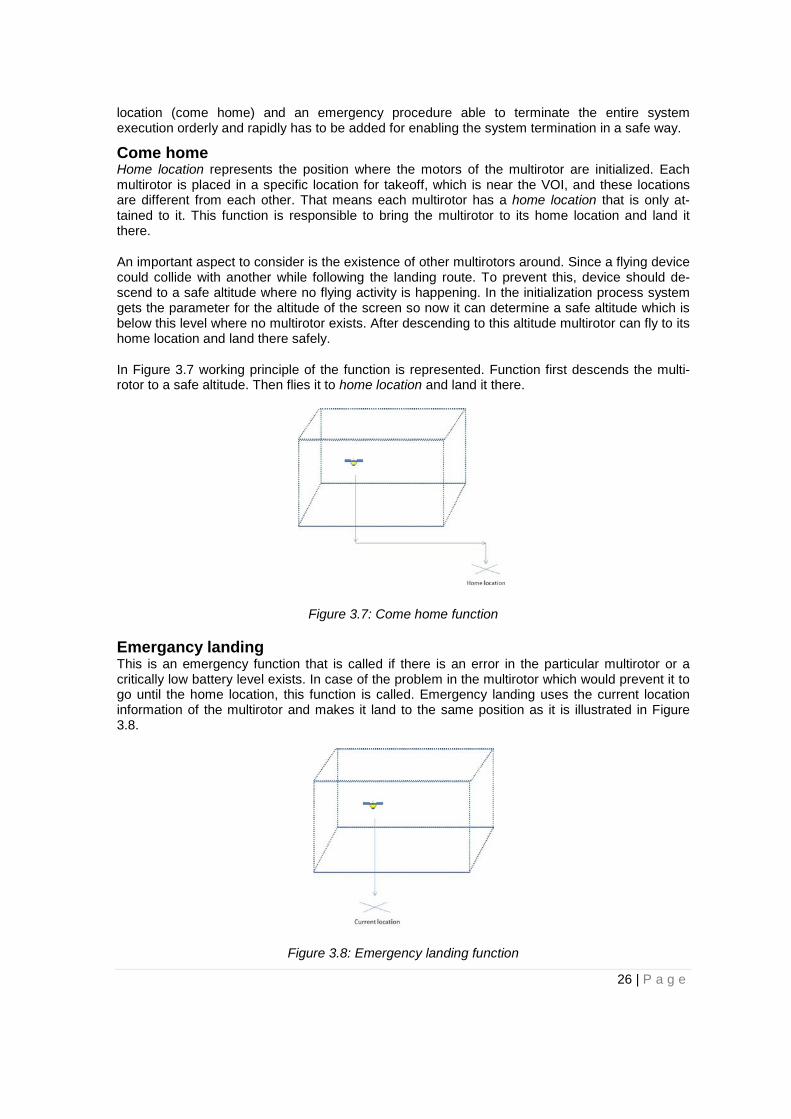
Come home Home location represents the position where the motors of the multirotor are initialized. Each multirotor is placed in a specific location for takeoff, which is near the VOI, and these locations are different from each other. That means each multirotor has a home location that is only at-tained to it. This function is responsible to bring the multirotor to its home location and land it there.
An important aspect to consider is the existence of other multirotors around. Since a flying device could collide with another while following the landing route. To prevent this, device should de-scend to a safe altitude where no flying activity is happening. In the initialization process system gets the parameter for the altitude of the screen so now it can determine a safe altitude which is below this level where no multirotor exists. After descending to this altitude multirotor can fly to its home location and land there safely.
In Figure 3.7 working principle of the function is represented. Function first descends the multi-rotor to a safe altitude. Then flies it to home location and land it there.
Figure 3.7: Come home function
Emergancy landing This is an emergency function that is called if there is an error in the particular multirotor or a critically low battery level exists. In case of the problem in the multirotor which would prevent it to go until the home location, this function is called. Emergency landing uses the current location information of the multirotor and makes it land to the same position as it is illustrated in Figure 3.8.
Figure 3.8: Emergency landing function
26 | P a g e
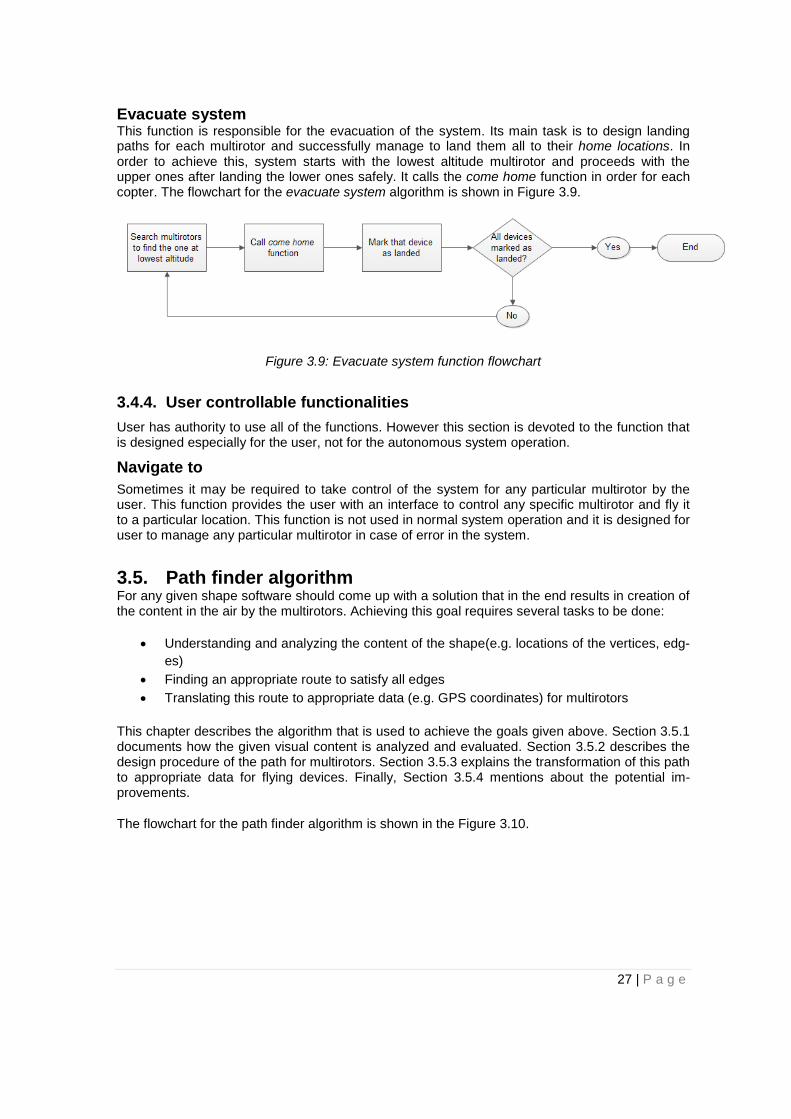
Evacuate system This function is responsible for the evacuation of the system. Its main task is to design landing paths for each multirotor and successfully manage to land them all to their home locations. In order to achieve this, system starts with the lowest altitude multirotor and proceeds with the upper ones after landing the lower ones safely. It calls the come home function in order for each copter. The flowchart for the evacuate system algorithm is shown in Figure 3.9.
Figure 3.9: Evacuate system function flowchart
3.4.4. User controllable functionalities User has authority to use all of the functions. However this section is devoted to the function that is designed especially for the user, not for the autonomous system operation.
Navigate to Sometimes it may be required to take control of the system for any particular multirotor by the user. This function provides the user with an interface to control any specific multirotor and fly it to a particular location. This function is not used in normal system operation and it is designed for user to manage any particular multirotor in case of error in the system.
3.5. Path finder algorithm For any given shape software should come up with a solution that in the end results in creation of the content in the air by the multirotors. Achieving this goal requires several tasks to be done:
• Understanding and analyzing the content of the shape(e.g. locations of the vertices, edg-es)
• Finding an appropriate route to satisfy all edges • Translating this route to appropriate data (e.g. GPS coordinates) for multirotors
This chapter describes the algorithm that is used to achieve the goals given above. Section 3.5.1 documents how the given visual content is analyzed and evaluated. Section 3.5.2 describes the design procedure of the path for multirotors. Section 3.5.3 explains the transformation of this path to appropriate data for flying devices. Finally, Section 3.5.4 mentions about the potential im-provements.
The flowchart for the path finder algorithm is shown in the Figure 3.10.
27 | P a g e
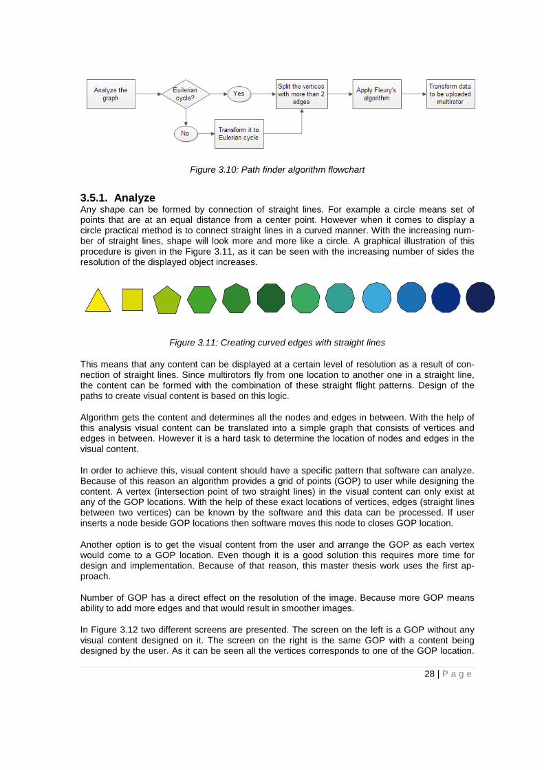
Figure 3.10: Path finder algorithm flowchart
3.5.1. Analyze Any shape can be formed by connection of straight lines. For example a circle means set of points that are at an equal distance from a center point. However when it comes to display a circle practical method is to connect straight lines in a curved manner. With the increasing num-ber of straight lines, shape will look more and more like a circle. A graphical illustration of this procedure is given in the Figure 3.11, as it can be seen with the increasing number of sides the resolution of the displayed object increases.
Figure 3.11: Creating curved edges with straight lines
This means that any content can be displayed at a certain level of resolution as a result of con-nection of straight lines. Since multirotors fly from one location to another one in a straight line, the content can be formed with the combination of these straight flight patterns. Design of the paths to create visual content is based on this logic.
Algorithm gets the content and determines all the nodes and edges in between. With the help of this analysis visual content can be translated into a simple graph that consists of vertices and edges in between. However it is a hard task to determine the location of nodes and edges in the visual content.
In order to achieve this, visual content should have a specific pattern that software can analyze. Because of this reason an algorithm provides a grid of points (GOP) to user while designing the content. A vertex (intersection point of two straight lines) in the visual content can only exist at any of the GOP locations. With the help of these exact locations of vertices, edges (straight lines between two vertices) can be known by the software and this data can be processed. If user inserts a node beside GOP locations then software moves this node to closes GOP location.
Another option is to get the visual content from the user and arrange the GOP as each vertex would come to a GOP location. Even though it is a good solution this requires more time for design and implementation. Because of that reason, this master thesis work uses the first ap-proach.
Number of GOP has a direct effect on the resolution of the image. Because more GOP means ability to add more edges and that would result in smoother images.
In Figure 3.12 two different screens are presented. The screen on the left is a GOP without any visual content designed on it. The screen on the right is the same GOP with a content being designed by the user. As it can be seen all the vertices corresponds to one of the GOP location.
28 | P a g e
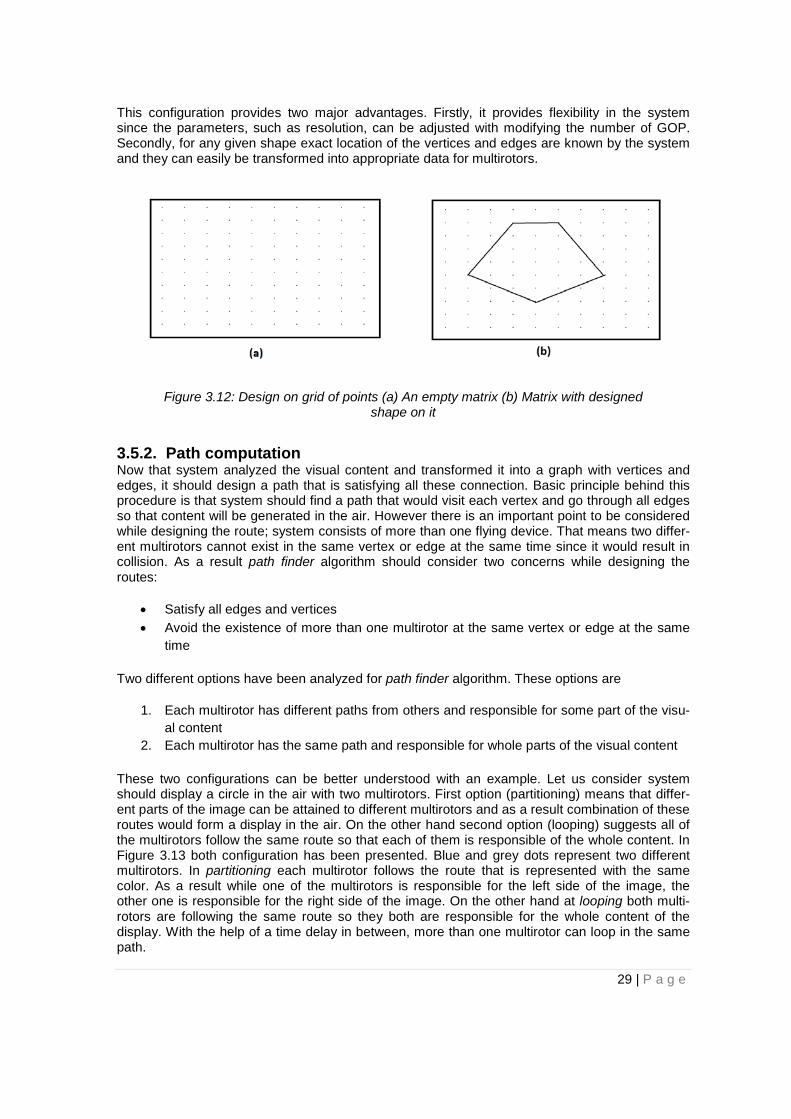
This configuration provides two major advantages. Firstly, it provides flexibility in the system since the parameters, such as resolution, can be adjusted with modifying the number of GOP. Secondly, for any given shape exact location of the vertices and edges are known by the system and they can easily be transformed into appropriate data for multirotors.
Figure 3.12: Design on grid of points (a) An empty matrix (b) Matrix with designed shape on it
3.5.2. Path computation Now that system analyzed the visual content and transformed it into a graph with vertices and edges, it should design a path that is satisfying all these connection. Basic principle behind this procedure is that system should find a path that would visit each vertex and go through all edges so that content will be generated in the air. However there is an important point to be considered while designing the route; system consists of more than one flying device. That means two differ-ent multirotors cannot exist in the same vertex or edge at the same time since it would result in collision. As a result path finder algorithm should consider two concerns while designing the routes:
• Satisfy all edges and vertices • Avoid the existence of more than one multirotor at the same vertex or edge at the same
time
Two different options have been analyzed for path finder algorithm. These options are
1. Each multirotor has different paths from others and responsible for some part of the visu-al content
2. Each multirotor has the same path and responsible for whole parts of the visual content
These two configurations can be better understood with an example. Let us consider system should display a circle in the air with two multirotors. First option (partitioning) means that differ-ent parts of the image can be attained to different multirotors and as a result combination of these routes would form a display in the air. On the other hand second option (looping) suggests all of the multirotors follow the same route so that each of them is responsible of the whole content. In Figure 3.13 both configuration has been presented. Blue and grey dots represent two different multirotors. In partitioning each multirotor follows the route that is represented with the same color. As a result while one of the multirotors is responsible for the left side of the image, the other one is responsible for the right side of the image. On the other hand at looping both multi-rotors are following the same route so they both are responsible for the whole content of the display. With the help of a time delay in between, more than one multirotor can loop in the same path.
29 | P a g e

Figure 3.13: Path finding algorithm options (a) Partitioning (b) Looping
In order to decide which option is better, advantages and disadvantages of both algorithm can be analyzed.
The main advantage of partitioning is its small chance of collision. Because both multirotors are flying in independent routes they have no intersection and that decreases the chance of collision in the air. On the other hand it has two major disadvantages. Firstly, both of the multirotors are oscillating at two sides of the circle and this creates and oscillation in the image. That means the continuity of the image will be distorted and audience will see it as an oscillation which decreases the image quality. Secondly, it requires system to divide content of the display into different parts and design different routes for each multirotor. That increases the complexity of the process, also when there is a change in the number of the multirotors all routes have to be designed again accordingly.
The main drawback of looping is its higher chance of collision. Because both multirotors are following the same route if there is a mistake in time delay, they can easily collide. However it has several advantages to compensate this disadvantage. Firstly, same route is designed for each multirotor so less complexity in path finder algorithm. Secondly, since all the multirotors are following the same route, changing the number of multirotors doesn’t require the restart of the route designing procedure. All system has to do is to decrease the time delay in between multi-rotors if a new multirotor is added so that more flying device can fit in the route and vice versa if a multirotor is removed from the system. Thirdly, it has a good scalability perspective. The content can be displayed even with one multirotor but increasing number of multirotors will result in higher resolution in the image because more visible voxels will be in the display.
Table 3.2: Advantages and disadvantages of navigations systems
Advantages Disadvantages Partitioning Low risk of collision Poor quality of the image, high
complexity Looping Simplicity of process, scalabil-
ity, adjustable resolution of the image
Higher chance of collision
Because of the given advantages looping provides better solution. However it brings some extra problems with more complicated contents. The main principle is to create a loop and put all of the multirotors in the same loop with time delay in between. Drawing a circle is easy since it can be looped easily however when it comes to more complicated shapes it is a hard task to find a route that can both visit all edges and can be looped. In order to achieve this, the given graph should have the following property; a trail should exist such that it starts from any node, visits all the edges and ends up in the same node so that it can be looped.
30 | P a g e

Eulerian Cycle Our solution comes from the graph theory proposed by Euler and known as Eulerian Cycle. What this theory proposes is as follows: if there is a graph where each vertex has an even number of edges then a trail can be generated that starts from any of the given vertex, visit all edges and finish at the same vertex. Therefore if the given content has the properties of Eulerian Cycle then it can be looped. However the content that is designed by the user does not necessarily have to be an Eulerian Cycle. In that case the system should transform the given shape to an Eulerian Cycle first, for which a route can be designed.
That brings the question how to transform a given graph to an Eulerian Cycle. Since the require-ment is to have even number of edges for each vertices, all vertices should be transformed in a way that each of them has an even number of edges. This can be done by adding extra edges between vertices with odd number of edges. For example if the content that is desired to be displayed is letter “E”, then there are six vertices in which four of them have odd number of edges (vertices 2,4,6,6 in Figure 3.14). If these four vertices are connected to each other with extra edges then the graph is transformed into an Eulerian Cycle as shown in Figure 3.14. After this process a trail can be generated which starts from any of the vertices, satisfies all of the edges and ends in the same vertex.
Figure 3.14: Transforming a graph to Eulerian Cycle (a) Original graph (b) Transformed graph
Even though this process successfully creates an Eulerian Cycle, it brings two major problems with it. Firstly, since new edges are added the original image has been altered and this will cause a distortion in the content. This problem can be solved with the adjustment of the visibility of the flying light. As it is mentioned in the previous chapters, each multirotor has its own light source and smoke generator to create a visible node in the air. Switching off the light source will result in the invisibility of the flying vehicle. With this procedure each multirotor can switch off its light while going through any of the extra added lines so that these lines will not be seen by the audience even though they exist. As a result original content will be protected and seen by the audience. Secondly, new edges can intersect with already existing edges. While adding extra edges soft-ware should connect the nearest vertices to each other to shorten the total path length. However this new edge can go through an existing edge and that can cause a collision in the air. Prevent-ing these potential intersections is possible with using the extra layer at different dimension to the display as shown in Figure 3.15. When a multirotor is about to go through an extra added edge it should change its layer so that even if the edges were to intersect, multirotors wouldn’t collide since they are in different layers. With the help these two solutions now system can create an Eulerian Cycle without causing distortion in the image and potential collisions.
31 | P a g e
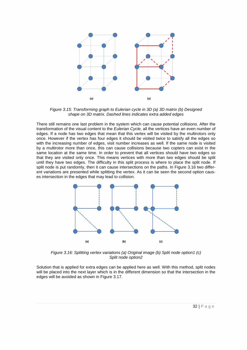
Figure 3.15: Transforming graph to Eulerian cycle in 3D (a) 3D matrix (b) Designed shape on 3D matrix. Dashed lines indicates extra added edges
There still remains one last problem in the system which can cause potential collisions. After the transformation of the visual content to the Eulerian Cycle, all the vertices have an even number of edges. If a node has two edges that mean that this vertex will be visited by the multirotors only once. However if the vertex has four edges it should be visited twice to satisfy all the edges so with the increasing number of edges, visit number increases as well. If the same node is visited by a multirotor more than once, this can cause collisions because two copters can exist in the same location at the same time. In order to prevent that all vertices should have two edges so that they are visited only once. This means vertices with more than two edges should be split until they have two edges. The difficulty in this split process is where to place the split node. If split node is put randomly, then it can cause intersections on the paths. In Figure 3.16 two differ-ent variations are presented while splitting the vertex. As it can be seen the second option caus-es intersection in the edges that may lead to collision.
Figure 3.16: Splitting vertex variations (a) Original image (b) Split node option1 (c) Split node option2
Solution that is applied for extra edges can be applied here as well. With this method, split nodes will be placed into the next layer which is in the different dimension so that the intersection in the edges will be avoided as shown in Figure 3.17.
32 | P a g e
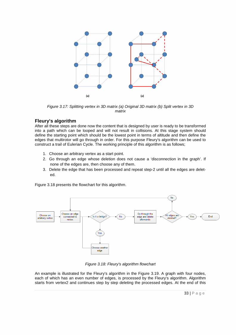
Figure 3.17: Splitting vertex in 3D matrix (a) Original 3D matrix (b) Split vertex in 3D matrix
Fleury’s algorithm After all these steps are done now the content that is designed by user is ready to be transformed into a path which can be looped and will not result in collisions. At this stage system should define the starting point which should be the lowest point in terms of altitude and then define the edges that multirotor will go through in order. For this purpose Fleury’s algorithm can be used to construct a trail of Eulerian Cycle. The working principle of this algorithm is as follows;
1. Choose an arbitrary vertex as a start point. 2. Go through an edge whose deletion does not cause a ‘disconnection in the graph’. If
none of the edges are, then choose any of them. 3. Delete the edge that has been processed and repeat step-2 until all the edges are delet-
ed.
Figure 3.18 presents the flowchart for this algorithm.
Figure 3.18: Fleury's algorithm flowchart
An example is illustrated for the Fleury’s algorithm in the Figure 3.19. A graph with four nodes, each of which has an even number of edges, is processed by the Fleury’s algorithm. Algorithm starts from vertex2 and continues step by step deleting the processed edges. At the end of this
33 | P a g e
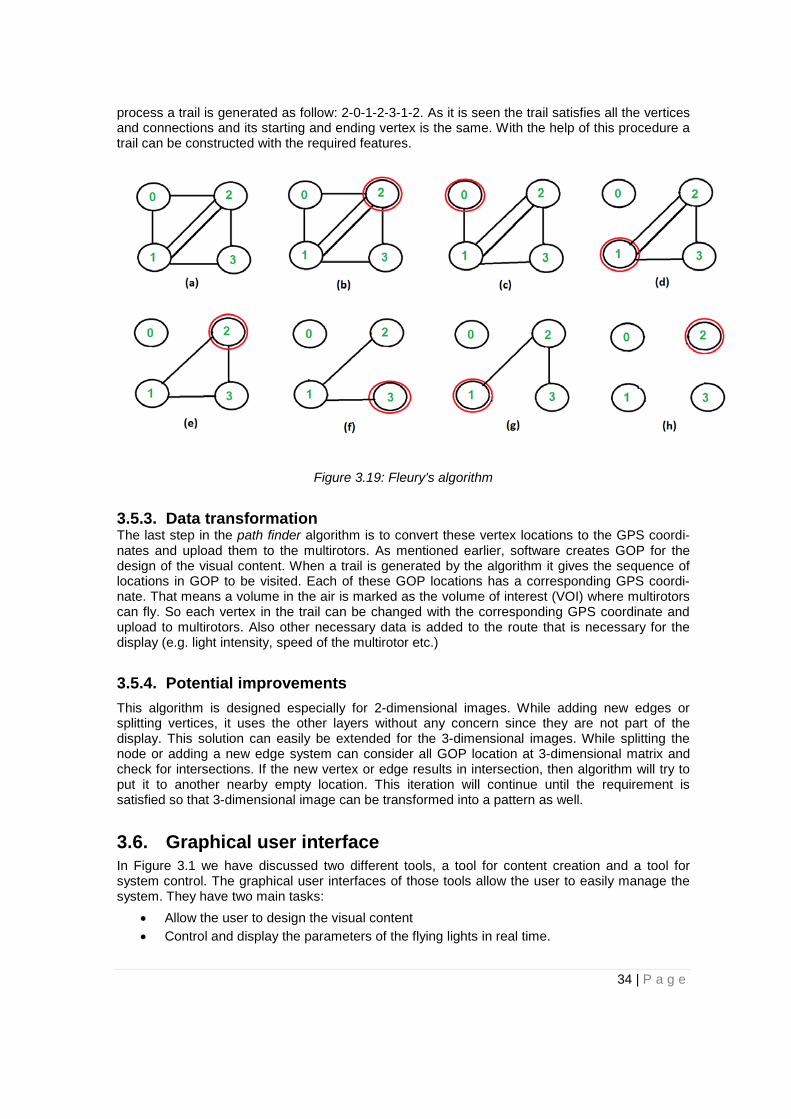
process a trail is generated as follow: 2-0-1-2-3-1-2. As it is seen the trail satisfies all the vertices and connections and its starting and ending vertex is the same. With the help of this procedure a trail can be constructed with the required features.
Figure 3.19: Fleury's algorithm
3.5.3. Data transformation The last step in the path finder algorithm is to convert these vertex locations to the GPS coordi-nates and upload them to the multirotors. As mentioned earlier, software creates GOP for the design of the visual content. When a trail is generated by the algorithm it gives the sequence of locations in GOP to be visited. Each of these GOP locations has a corresponding GPS coordi-nate. That means a volume in the air is marked as the volume of interest (VOI) where multirotors can fly. So each vertex in the trail can be changed with the corresponding GPS coordinate and upload to multirotors. Also other necessary data is added to the route that is necessary for the display (e.g. light intensity, speed of the multirotor etc.)
3.5.4. Potential improvements This algorithm is designed especially for 2-dimensional images. While adding new edges or splitting vertices, it uses the other layers without any concern since they are not part of the display. This solution can easily be extended for the 3-dimensional images. While splitting the node or adding a new edge system can consider all GOP location at 3-dimensional matrix and check for intersections. If the new vertex or edge results in intersection, then algorithm will try to put it to another nearby empty location. This iteration will continue until the requirement is satisfied so that 3-dimensional image can be transformed into a pattern as well.
3.6. Graphical user interface In Figure 3.1 we have discussed two different tools, a tool for content creation and a tool for system control. The graphical user interfaces of those tools allow the user to easily manage the system. They have two main tasks:
• Allow the user to design the visual content • Control and display the parameters of the flying lights in real time.
34 | P a g e
Two windows are designed for each of the tasks that are mentioned above. Content designer window is responsible for the design of visual content and control window is responsible for the control and display of the system.
3.6.1. Content designer window Content designer tool provides user the means to design a visual content for the digital display. As mentioned before, software creates GOP in the air which is basically a 3-dimensional matrix and 3-dimensional images can be displayed. However due to the time limitations, 3-dimensional visual effects are not designed in this master thesis work.
The functionalities for these tools can be listed as follows:
• Shape design: Tool provides user the necessary tools to design a shape to be displayed. User can add or edit drawings with the help of this functionality.
• Effects design: Different effects for the display can be designed with the help of this tool. For example the light intensity for different part of the visual content can be arranged ac-cordingly. Also audio effects can be added to the show. These effects can be extended to a wider range with the future improvements.
• Analyze the design: Tool analyzes the visual content to locate the vertices and edges. Af-ter all these points are located, visual content can be represented as a graph consisting of vertices and edges.
• Evaluate the design: Now that tool transformed the content to a graph, path finder algo-rithm can be applied. However important part here is the location of vertices. Each vertex should be located in one of the GOP locations so that it can be translated into GPS coor-dinates.
Content designer window provides a horizontal or vertical layer of GOP. On which layer to design can be chosen from the interface. Also for example when horizontal layer is chosen, there are still more than one horizontal layer in the GOP. So the tool lets user to choose which layer to work on.
In the beginning there is only one node at the screen. When a mouse is clicked anywhere in the screen, interface adds a new vertex to the closest grid point location and an edge between the first node and the newly added node. Putting the new vertex to the closest point location is to let user to design at the given resolution, because only the given GOP locations uploaded to the multirotors as GPS data. After that when mouse is clicked again at another location, software places a new vertex to GOP location closest to that location and an edge between the node added before (second node in this scenario) and the newly added node (third node in this scenar-io). However with this process a shape can be created only in a continuous line because the edge is always constructed between the last vertex and new added vertex. Because of that interface should let user to generate any edge between any vertices.
In order to construct an edge between the newly added node and any other already existing node, users first click on the node that they want to construct the edge from and then to location where the edge should end. With the help of this function an edge can be generated from any location to any location in the grid of points. The procedure of creating a visual content is illus-trated in the Figure 3.20. Numbers near the nodes represents the order of generating them. As it can be seen first option results in a continuous line while second option can create more compli-cated shapes.
35 | P a g e

Figure 3.20: Creation of the visual content with adding new vertices (a) System ads the new edge only between the last vertex and the new added one (b) Edge can be
added from any vertex
Software also lets user to modify the any vertex in the content. Moving to vertex also will result in modifying the edges connected to that vertex accordingly. An illustration is given in Figure 3.21.
Figure 3.21: Node modify scenario
With the help of the functionalities mentioned above, user can design a visual content that can be displayed in the screen. The flowchart for the content designer tool is given in Figure 3.22.
Figure 3.22: Content designer tool flowchart
36 | P a g e
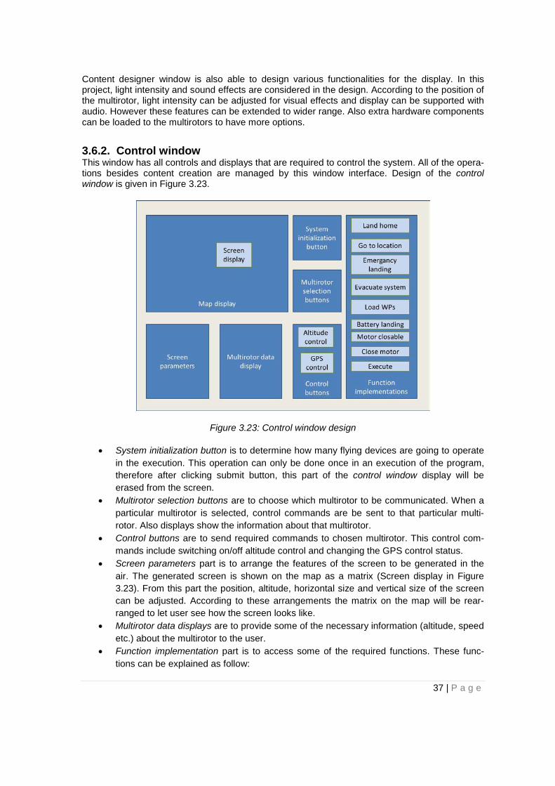
Content designer window is also able to design various functionalities for the display. In this project, light intensity and sound effects are considered in the design. According to the position of the multirotor, light intensity can be adjusted for visual effects and display can be supported with audio. However these features can be extended to wider range. Also extra hardware components can be loaded to the multirotors to have more options.
3.6.2. Control window This window has all controls and displays that are required to control the system. All of the opera-tions besides content creation are managed by this window interface. Design of the control window is given in Figure 3.23.
Figure 3.23: Control window design
• System initialization button is to determine how many flying devices are going to operate in the execution. This operation can only be done once in an execution of the program, therefore after clicking submit button, this part of the control window display will be erased from the screen.
• Multirotor selection buttons are to choose which multirotor to be communicated. When a particular multirotor is selected, control commands are be sent to that particular multi-rotor. Also displays show the information about that multirotor.
• Control buttons are to send required commands to chosen multirotor. This control com-mands include switching on/off altitude control and changing the GPS control status.
• Screen parameters part is to arrange the features of the screen to be generated in the air. The generated screen is shown on the map as a matrix (Screen display in Figure 3.23). From this part the position, altitude, horizontal size and vertical size of the screen can be adjusted. According to these arrangements the matrix on the map will be rear-ranged to let user see how the screen looks like.
• Multirotor data displays are to provide some of the necessary information (altitude, speed etc.) about the multirotor to the user.
• Function implementation part is to access some of the required functions. These func-tions can be explained as follow:
37 | P a g e
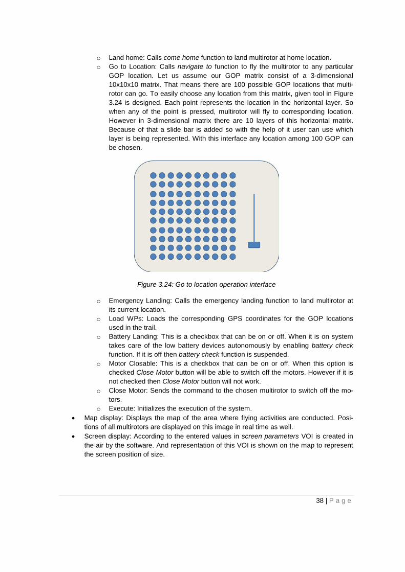
o Land home: Calls come home function to land multirotor at home location. o Go to Location: Calls navigate to function to fly the multirotor to any particular
GOP location. Let us assume our GOP matrix consist of a 3-dimensional 10x10x10 matrix. That means there are 100 possible GOP locations that multi-rotor can go. To easily choose any location from this matrix, given tool in Figure 3.24 is designed. Each point represents the location in the horizontal layer. So when any of the point is pressed, multirotor will fly to corresponding location. However in 3-dimensional matrix there are 10 layers of this horizontal matrix. Because of that a slide bar is added so with the help of it user can use which layer is being represented. With this interface any location among 100 GOP can be chosen.
Figure 3.24: Go to location operation interface
o Emergency Landing: Calls the emergency landing function to land multirotor at its current location.
o Load WPs: Loads the corresponding GPS coordinates for the GOP locations used in the trail.
o Battery Landing: This is a checkbox that can be on or off. When it is on system takes care of the low battery devices autonomously by enabling battery check function. If it is off then battery check function is suspended.
o Motor Closable: This is a checkbox that can be on or off. When this option is checked Close Motor button will be able to switch off the motors. However if it is not checked then Close Motor button will not work.
o Close Motor: Sends the command to the chosen multirotor to switch off the mo-tors.
o Execute: Initializes the execution of the system. • Map display: Displays the map of the area where flying activities are conducted. Posi-
tions of all multirotors are displayed on this image in real time as well. • Screen display: According to the entered values in screen parameters VOI is created in
the air by the software. And representation of this VOI is shown on the map to represent the screen position of size.
38 | P a g e
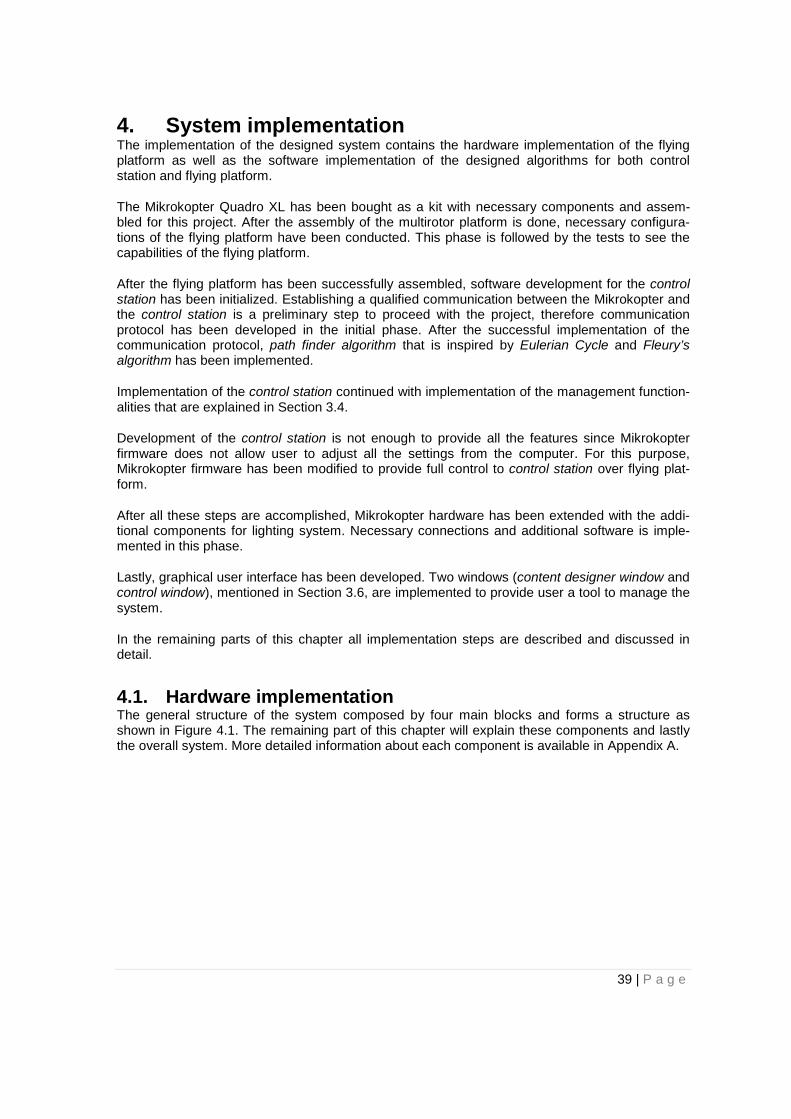
4. System implementation The implementation of the designed system contains the hardware implementation of the flying platform as well as the software implementation of the designed algorithms for both control station and flying platform.
The Mikrokopter Quadro XL has been bought as a kit with necessary components and assem-bled for this project. After the assembly of the multirotor platform is done, necessary configura-tions of the flying platform have been conducted. This phase is followed by the tests to see the capabilities of the flying platform.
After the flying platform has been successfully assembled, software development for the control station has been initialized. Establishing a qualified communication between the Mikrokopter and the control station is a preliminary step to proceed with the project, therefore communication protocol has been developed in the initial phase. After the successful implementation of the communication protocol, path finder algorithm that is inspired by Eulerian Cycle and Fleury’s algorithm has been implemented.
Implementation of the control station continued with implementation of the management function-alities that are explained in Section 3.4.
Development of the control station is not enough to provide all the features since Mikrokopter firmware does not allow user to adjust all the settings from the computer. For this purpose, Mikrokopter firmware has been modified to provide full control to control station over flying plat-form.
After all these steps are accomplished, Mikrokopter hardware has been extended with the addi-tional components for lighting system. Necessary connections and additional software is imple-mented in this phase.
Lastly, graphical user interface has been developed. Two windows (content designer window and control window), mentioned in Section 3.6, are implemented to provide user a tool to manage the system.
In the remaining parts of this chapter all implementation steps are described and discussed in detail.
4.1. Hardware implementation The general structure of the system composed by four main blocks and forms a structure as shown in Figure 4.1. The remaining part of this chapter will explain these components and lastly the overall system. More detailed information about each component is available in Appendix A.
39 | P a g e
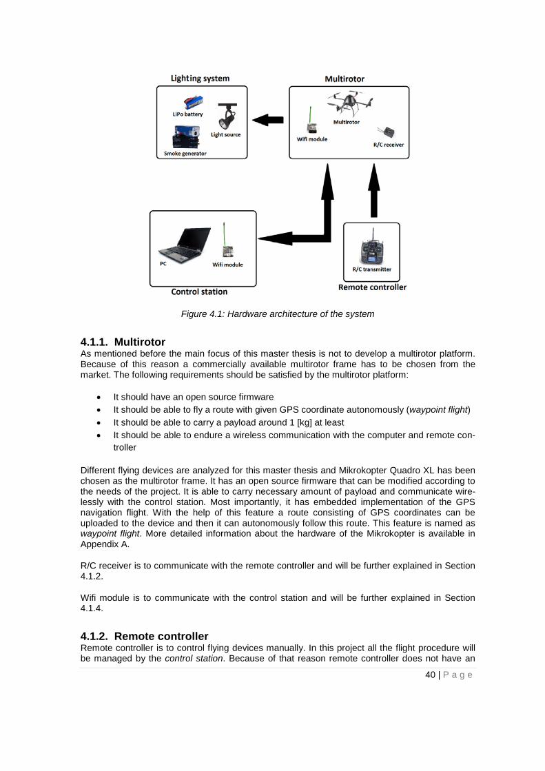
Figure 4.1: Hardware architecture of the system
4.1.1. Multirotor As mentioned before the main focus of this master thesis is not to develop a multirotor platform. Because of this reason a commercially available multirotor frame has to be chosen from the market. The following requirements should be satisfied by the multirotor platform:
• It should have an open source firmware • It should be able to fly a route with given GPS coordinate autonomously (waypoint flight) • It should be able to carry a payload around 1 [kg] at least • It should be able to endure a wireless communication with the computer and remote con-
troller
Different flying devices are analyzed for this master thesis and Mikrokopter Quadro XL has been chosen as the multirotor frame. It has an open source firmware that can be modified according to the needs of the project. It is able to carry necessary amount of payload and communicate wire-lessly with the control station. Most importantly, it has embedded implementation of the GPS navigation flight. With the help of this feature a route consisting of GPS coordinates can be uploaded to the device and then it can autonomously follow this route. This feature is named as waypoint flight. More detailed information about the hardware of the Mikrokopter is available in Appendix A.
R/C receiver is to communicate with the remote controller and will be further explained in Section 4.1.2.
Wifi module is to communicate with the control station and will be further explained in Section 4.1.4.
4.1.2. Remote controller Remote controller is to control flying devices manually. In this project all the flight procedure will be managed by the control station. Because of that reason remote controller does not have an
40 | P a g e
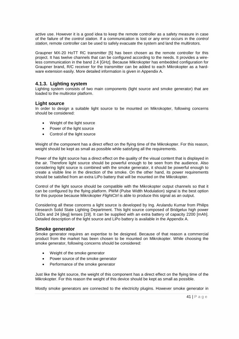
active use. However it is a good idea to keep the remote controller as a safety measure in case of the failure of the control station. If a communication is lost or any error occurs in the control station, remote controller can be used to safely evacuate the system and land the multirotors.
Graupner MX-20 HoTT RC transmitter [5] has been chosen as the remote controller for this project. It has twelve channels that can be configured according to the needs. It provides a wire-less communication in the band 2.4 [GHz]. Because Mikrokopter has embedded configuration for Graupner brand, R/C receiver for the transmitter can be added to each Mikrokopter as a hard-ware extension easily. More detailed information is given in Appendix A.
4.1.3. Lighting system Lighting system consists of two main components (light source and smoke generator) that are loaded to the multirotor platform.
Light source In order to design a suitable light source to be mounted on Mikrokopter, following concerns should be considered:
• Weight of the light source • Power of the light source • Control of the light source
Weight of the component has a direct effect on the flying time of the Mikrokopter. For this reason, weight should be kept as small as possible while satisfying all the requirements.
Power of the light source has a direct effect on the quality of the visual content that is displayed in the air. Therefore light source should be powerful enough to be seen from the audience. Also considering light source is combined with the smoke generator, it should be powerful enough to create a visible line in the direction of the smoke. On the other hand, its power requirements should be satisfied from an extra LiPo battery that will be mounted on the Mikrokopter.
Control of the light source should be compatible with the Mikrokopter output channels so that it can be configured by the flying platform. PWM (Pulse Width Modulation) signal is the best option for this purpose because Mikrokopter FlightCtrl is able to produce this signal as an output.
Considering all these concerns a light source is developed by Ing. Arulandu Kumar from Philips Research Solid State Lighting Department. This light source composed of Bridgelux high power LEDs and 24 [deg] lenses [19]. It can be supplied with an extra battery of capacity 2200 [mAh]. Detailed description of the light source and LiPo battery is available in the Appendix A.
Smoke generator Smoke generator requires an expertise to be designed. Because of that reason a commercial product from the market has been chosen to be mounted on Mikrokopter. While choosing the smoke generator, following concerns should be considered:
• Weight of the smoke generator • Power source of the smoke generator • Performance of the smoke generator
Just like the light source, the weight of this component has a direct effect on the flying time of the Mikrokopter. For this reason the weight of this device should be kept as small as possible.
Mostly smoke generators are connected to the electricity plugins. However smoke generator in
41 | P a g e

this project should be able to work with a battery so that it can be carried by the multirotor.
Smoke generator should be powerful enough to create a visible smoke in the direction of the light. The more powerful smoke will result in better visibility of the light in the air. However in-creasing power usually means increasing the weight, so the optimum combination should be chosen.
Tiny FX smoke generator from Look Solutions is chosen to be mounted on the Mikrokopter as smoke generator. Its weight is feasible for Mikrokopter and it can work with a battery. More detailed information about the smoke generator is available in Appendix A.
4.1.4. Control station Control station acts as the brain of the system. It communicates with each multirotor, processes the data they sent and sends required commands to them. Control station is a simple personal computer which runs the source code for the software.
In addition to the computer a wireless module is required to provide a wireless communication with the flying devices. Wi.232 wireless module is chosen for this purpose. This module is devel-oped by MikroKopter and it has an embedded communication protocol with FlightCtrl. Because of that no additional configuration is required. It has four different channels available which means system can communicate up to four Mikrokopters simultaneously. More detailed information is given in Appendix A.
4.1.5. Overall system This project consists of one control station, one remote controller and two flying light platforms.
All basic components for the multirotors are purchased with the product and assembled together in this project.
In Figure 4.2 picture of a flying platform with all hardware parts implemented is provided. Original Mikrokopter hardware is placed inside the semi sphere cover at top. Rest of the additional hard-ware extensions are placed underneath this layer as it can be seen from the Figure 4.2.
Figure 4.2: Flying light component
First layer below the frame is for the LiPo battery of the quadrotor. Since it is directly providing
42 | P a g e

power for the quadrotor, it is placed closer to the frame.
Second layer, which is underneath the first layer, includes several components as listed below:
• The Graupner receiver which is responsible for communicating with the remote controller. • Wi.232 wireless module that is responsible for the communication with the control station. • Wireless receiver for the smoke generator. • Battery for the light source • Battery for the smoke generator.
Third layer, which is the last one, has the light source and the smoke generator. While placing them, two concerns have been considered. Firstly, center of the mass of the system should be kept in balance. This is important because otherwise flying device cannot maintain a proper flight which in turn would result in distorted images in the air. Secondly, visibility of the system should be maximized. Different tests have been conducted to measure the smoke length with different positions and angles to find out the optimized position. Because there is a strong airflow around the multirotor, the position of the smoke generator directly affects the smoke size. Tests have shown that if smoke generator is places in the middle of four propellers looking downward, it results in satisfactory performance. For these two reasons the light source and the smoke gener-ator has been placed as it is shown in the Figure 4.3.
Figure 4.3: Light source and smoke generator
Hardware components for the control station have been shown in the Figure 4.4. Control station consists of a notebook and Wi.232 wireless modules for each multirotor (two multirotors used in this project).
43 | P a g e
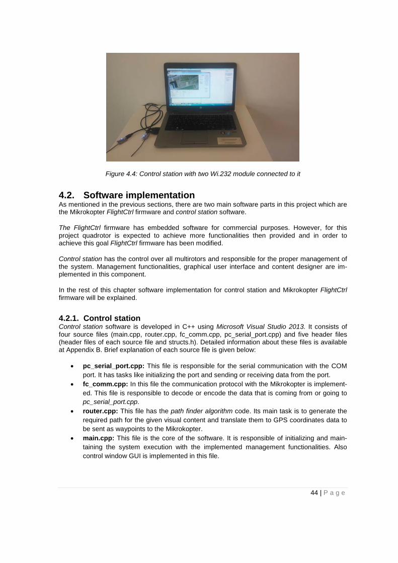
Figure 4.4: Control station with two Wi.232 module connected to it
4.2. Software implementation As mentioned in the previous sections, there are two main software parts in this project which are the Mikrokopter FlightCtrl firmware and control station software.
The FlightCtrl firmware has embedded software for commercial purposes. However, for this project quadrotor is expected to achieve more functionalities then provided and in order to achieve this goal FlightCtrl firmware has been modified.
Control station has the control over all multirotors and responsible for the proper management of the system. Management functionalities, graphical user interface and content designer are im-plemented in this component.
In the rest of this chapter software implementation for control station and Mikrokopter FlightCtrl firmware will be explained.
4.2.1. Control station Control station software is developed in C++ using Microsoft Visual Studio 2013. It consists of four source files (main.cpp, router.cpp, fc_comm.cpp, pc_serial_port.cpp) and five header files (header files of each source file and structs.h). Detailed information about these files is available at Appendix B. Brief explanation of each source file is given below:
• pc_serial_port.cpp: This file is responsible for the serial communication with the COM port. It has tasks like initializing the port and sending or receiving data from the port.
• fc_comm.cpp: In this file the communication protocol with the Mikrokopter is implement-ed. This file is responsible to decode or encode the data that is coming from or going to pc_serial_port.cpp.
• router.cpp: This file has the path finder algorithm code. Its main task is to generate the required path for the given visual content and translate them to GPS coordinates data to be sent as waypoints to the Mikrokopter.
• main.cpp: This file is the core of the software. It is responsible of initializing and main-taining the system execution with the implemented management functionalities. Also control window GUI is implemented in this file.
44 | P a g e
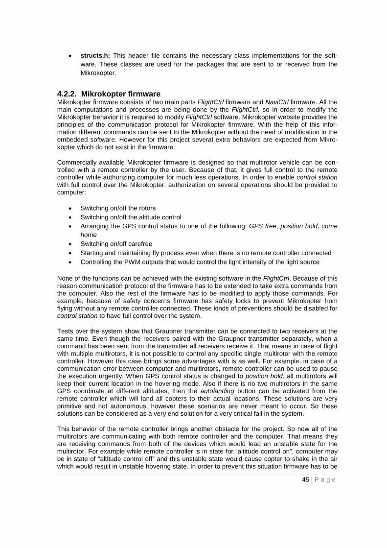
• structs.h: This header file contains the necessary class implementations for the soft-ware. These classes are used for the packages that are sent to or received from the Mikrokopter.
4.2.2. Mikrokopter firmware Mikrokopter firmware consists of two main parts FlightCtrl firmware and NaviCtrl firmware. All the main computations and processes are being done by the FlightCtrl, so in order to modify the Mikrokopter behavior it is required to modify FlightCtrl software. Mikrokopter website provides the principles of the communication protocol for Mikrokopter firmware. With the help of this infor-mation different commands can be sent to the Mikrokopter without the need of modification in the embedded software. However for this project several extra behaviors are expected from Mikro-kopter which do not exist in the firmware.
Commercially available Mikrokopter firmware is designed so that multirotor vehicle can be con-trolled with a remote controller by the user. Because of that, it gives full control to the remote controller while authorizing computer for much less operations. In order to enable control station with full control over the Mikrokopter, authorization on several operations should be provided to computer:
• Switching on/off the rotors • Switching on/off the altitude control • Arranging the GPS control status to one of the following: GPS free, position hold, come
home • Switching on/off carefree • Starting and maintaining fly process even when there is no remote controller connected • Controlling the PWM outputs that would control the light intensity of the light source
None of the functions can be achieved with the existing software in the FlightCtrl. Because of this reason communication protocol of the firmware has to be extended to take extra commands from the computer. Also the rest of the firmware has to be modified to apply those commands. For example, because of safety concerns firmware has safety locks to prevent Mikrokopter from flying without any remote controller connected. These kinds of preventions should be disabled for control station to have full control over the system.
Tests over the system show that Graupner transmitter can be connected to two receivers at the same time. Even though the receivers paired with the Graupner transmitter separately, when a command has been sent from the transmitter all receivers receive it. That means in case of flight with multiple multirotors, it is not possible to control any specific single multirotor with the remote controller. However this case brings some advantages with is as well. For example, in case of a communication error between computer and multirotors, remote controller can be used to pause the execution urgently. When GPS control status is changed to position hold, all multirotors will keep their current location in the hovering mode. Also if there is no two multirotors in the same GPS coordinate at different altitudes, then the autolanding button can be activated from the remote controller which will land all copters to their actual locations. These solutions are very primitive and not autonomous, however these scenarios are never meant to occur. So these solutions can be considered as a very end solution for a very critical fail in the system.
This behavior of the remote controller brings another obstacle for the project. So now all of the multirotors are communicating with both remote controller and the computer. That means they are receiving commands from both of the devices which would lead an unstable state for the multirotor. For example while remote controller is in state for “altitude control on”, computer may be in state of “altitude control off” and this unstable state would cause copter to shake in the air which would result in unstable hovering state. In order to prevent this situation firmware has to be
45 | P a g e
modified to apply commands only from one of the devices at a time.
Before proposing a solution two factors have to be considered. Firstly, tests have shown that the communication quality and range of the Graupner transmitter – receiver pack is much better than Wi.232 wireless modules that are used for the communication with control station. Secondly, remote controller should take over the control of the system only when the control station com-munication channel has failed. That means control station cannot give authority to remote con-troller to take control over the system because it has already lost the communication. Considering these facts remote control should be able to take over the control of the system by itself without a need of authorization from the control station.
As a result firmware should be edited in such a way that it will be controlled by the control station but if necessary remote controller can take over the control by itself. For this purpose a switch at the remote controller will be responsible of taking over the control of the system. When it is off control station will have the full control over the system, however if it is switched on then Mikro-kopter will stop listening the control station and will only get commands from the remote control-ler.
Brief information about the source files that are modified is given below:
• fc.c: This file is the core of the FlightCtrl software. It contains the necessary code for the management of altitude control, carefree control, motor activation/deactivation and re-mote control connection. This part of the software is modified in order to let the control station to access and change those parameters.
• led.c: This file contains the necessary code to manage the switchable outputs of the FlightCtrl. It is modified to obtained desirable outputs for the LED indicators on the Mikro-kopter
• uart.c: This file contains the necessary code for wireless communication. Mikrokopter serial communication protocol is implemented in this part of the code. This file is modified to improve the communication protocol and add more functionality.
• spi.c: This file contains the necessary code to provide proper communication between NaviCtrl and FlightCtrl. Since the GPS data is managed by the NaviCtrl, options about the GPS control status (GPS free, position hold, come home) is managed in this function. In order to provide access to the GPS control status, this file is modified.
• timer0.c: This file contains the necessary code to generate the PWM pulse waves for driving servos. This signal is used to adjust the intensity of the light. This file is modified to provide the control of PWM output to the control station.
More detailed information is provided in the Appendix B.
FlightCtrl code has been modified and compiled by the use of the software named WinAVR. Then created .hex file is uploaded to the Mikrokopter by the help of the KopterTool program.
4.3. Communication protocol implementation There are two wireless communication protocols to be mentioned in this project. One is the unidirectional communication between Mikrokopter – remote controller and the other one is the bidirectional communication between Mikrokopter – the control station. This chapter explains these communication channels.
There is also a wired communication between the Mikrokopter – lighting system however it is explained in Section 4.1.
46 | P a g e
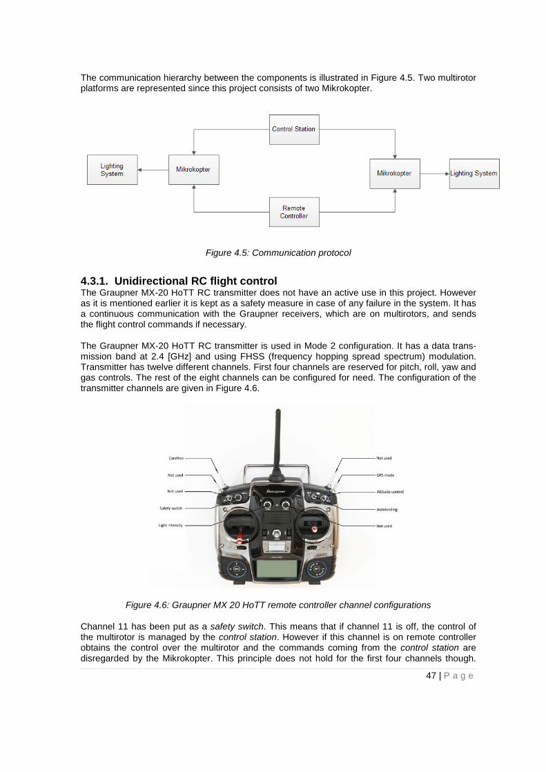
The communication hierarchy between the components is illustrated in Figure 4.5. Two multirotor platforms are represented since this project consists of two Mikrokopter.
Figure 4.5: Communication protocol
4.3.1. Unidirectional RC flight control The Graupner MX-20 HoTT RC transmitter does not have an active use in this project. However as it is mentioned earlier it is kept as a safety measure in case of any failure in the system. It has a continuous communication with the Graupner receivers, which are on multirotors, and sends the flight control commands if necessary.
The Graupner MX-20 HoTT RC transmitter is used in Mode 2 configuration. It has a data trans-mission band at 2.4 [GHz] and using FHSS (frequency hopping spread spectrum) modulation. Transmitter has twelve different channels. First four channels are reserved for pitch, roll, yaw and gas controls. The rest of the eight channels can be configured for need. The configuration of the transmitter channels are given in Figure 4.6.
Figure 4.6: Graupner MX 20 HoTT remote controller channel configurations
Channel 11 has been put as a safety switch. This means that if channel 11 is off, the control of the multirotor is managed by the control station. However if this channel is on remote controller obtains the control over the multirotor and the commands coming from the control station are disregarded by the Mikrokopter. This principle does not hold for the first four channels though.
47 | P a g e

Since they are reserved and cannot be changed, regardless of the safety switch they will affect the multirotor if there is any change in their status. But when they are at their neutral position the multirotor will keep following the commands from the control station.
4.3.2. Bidirectional system control Bidirectional system control communication covers all data exchange between the flying devices and the control station. Wi.232 wireless module is used to establish communication between Mikrokopter and the control station.
There are four different Wi.232 wireless modules, each of which is operating in different frequen-cy band. In this project two multirotor platforms have been used and each of them is equipped with a Wi.232 wireless module which has a different channel than other. The transceiver pair of each wireless module has been connected to the control station as well. However if system is to be operated with more than four multirotors, then Wi.232 wireless module has to be changed. Because two Wi.232 modules with same frequency band operation would cause a distortion in data transfer and there is only four different channels available in the market. Since the number of four multirotors has not been exceeded in this project, Wi.232 wireless modules met the needs of the system.
Communication between the wireless module and the computer is carried out with a USB cable. When the necessary drivers are installed, the computer sees the Wi.232 wireless module as an additional serial port.
Communication between the wireless module and the Mikrokopter FlightCtrl is carried out with a 10 pin connector. FlightCtrl uses the UART (Universal Asynchronous Receiver Transmitter) system for communication. The data exchange between the Wi.232 wireless module and FlightCtrl is done by the RS-232 communication standards.
The structure of the packages is given at Table 4.1.
Table 4.1: Mikrokopter serial communication protocol data structure[16]
Start-Byte
Address Byte
ID-Byte n Data-Bytes coded
CRC-Byte1
CRC-Byte2
Stop-Byte
'#' 'a'+ Addr 'V','D' etc. "modified-base64"
variable variable '\r'
Explanation of each byte is given below:
• Start Byte: Indicates the starting of a new package. • Address Byte: Identifies which Mikrokopter board the package is going or coming from.
In this project all communication is established with either FlightCtrl or NaviCtrl, so ad-dress byte is either “1” for FlightCtrl or “2” for NaviCtrl.
• ID Byte: Shows which functionality of the Mikrokopter is being sent or received in this package.
• N data Bytes: Includes the sent or received data by the Mikrokopter according to the operation that is indicated by the ID byte.
• CRC Bytes: CRC (Cyclic redundancy check) bytes are used to detect errors in the given package.
• Stop byte: Indicates the end of the package.
The functions that are used during this project are given in the Table 4.2.
48 | P a g e
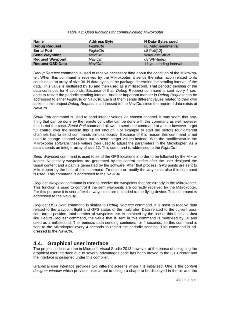
Table 4.2: Used functions for communicating Mikrokopter
Name Address Byte N Data-Bytes coed Debug Request FlightCtrl u8 AutoSendInterval Serial Poti FlightCtrl s8 Poti[12] Send Waypoint NaviCtrl WayPointStruct Request Waypoint NaviCtrl u8 WP-Index Request OSD Data NaviCtrl 1 byte sending interval
Debug Request command is used to receive necessary data about the condition of the Mikrokop-ter. When this command is received by the Mikrokopter, it sends the information related to its condition in an array of size 36. N data bytes in the package determine the sending interval of the data. This value is multiplied by 10 and then used as a millisecond. That periodic sending of the data continues for 4 seconds. Because of that, Debug Request command is sent every 4 sec-onds to restart the periodic sending interval. Another important manner is Debug Request can be addressed to either FlightCtrl or NaviCtrl. Each of them sends different values related to their own tasks. In this project Debug Request is addressed to the NaviCtrl since the required data exists at NaviCtrl.
Serial Poti command is used to send integer values via chosen channel. It may seem that any-thing that can be done by the remote controller can be done with this command as well however that is not the case. Serial Poti command allows to send one command at a time however to get full control over the system this is not enough. For example to start the motors four different channels has to send commands simultaneously. Because of this reason this command is not used to change channel values but to send integer values instead. With the modification in the Mikrokopter software these values then used to adjust the parameters in the Mikrokopter. As a data it sends an integer array of size 12. This command is addressed to the FlightCtrl.
Send Waypoint command is used to send the GPS locations in order to be followed by the Mikro-kopter. Necessary waypoints are generated by the control station after the user designed the visual content and a path is generated by the software. After that process, GPS points are sent to Mikrokopter by the help of this command. To delete or modify the waypoints also this command is used. This command is addressed to the NaviCtrl.
Request Waypoint command is used to receive the waypoints that are already in the Mikrokopter. This function is used to control if the sent waypoints are correctly received by the Mikrokopter. For this purpose it is sent after the waypoints are uploaded to the flying device. This command is addressed to the NaviCtrl.
Request OSD Data command is similar to Debug Request command. It is used to receive data related to the waypoint flight and GPS status of the multirotor. Data related to the current posi-tion, target position, total number of waypoints etc. is obtained by the use of this function. Just like Debug Request command, the value that is sent in this command is multiplied by 10 and used as a millisecond. This periodic data sending continues for 4 seconds, so this command is sent to the Mikrokopter every 4 seconds to restart the periodic sending. This command is ad-dressed to the NaviCtrl.
4.4. Graphical user interface The project code is written in Microsoft Visual Studio 2013 however at the phase of designing the graphical user interface due to several advantages code has been moved to the QT Creator and the interface is designed under this compiler.
Graphical user interface provides two different screens when it is initialized. One is the content designer window which provides user a tool to design a shape to be displayed in the air and the
49 | P a g e

second one is the control window where all the system configurations exist.
All GUI code has been added to the control station software.
4.4.1. Content designer window This window lets users to design any content they want in the given resolution options. For this purpose it creates a grid of points on the screen in which each point represents an actual GPS location in the air. As mentioned earlier, software creates a 3-dimensional matrix in the air how-ever 3-dimensional graphics has not been designed in this master thesis due to the time limita-tions. Given GOP on the screen represents either a horizontal layer or a vertical layer of this 3-dimensional matrix. With the help of the radio buttons user can choose in which layer content to be displayed. If a 3-dimensional matrix of size 10x10x10 is considered, there are 10 different horizontal and vertical layers. So with the help of the user interface any layer in one of the hori-zontal or vertical axes can be chosen as a screen to be displayed.
Figure 4.7: Content designer window
The procedure of creating a visual content is illustrated in the Figure 4.8.
50 | P a g e

Figure 4.8: Creation of the visual content. Black point shows where the mouse is clicked at that time. Alphabetic order of the figures is the same with the
chronological order
Software lets user to modify the previously added nodes as well. When an existing vertex is to be replaced, user should click on it and drag it to required position. Edges that are connected to that particular node will be arranged according to the new position autonomously. This procedure is illustrated in the Figure 4.9.
Figure 4.9: Node modifying procedure (a) Original content (b) Modified content; arrow shows the movement of the vertex; mouse is clicked in the beginning of arrow
and dragged in the given direction
If designed shape is not satisfactory and needs to be redesigned, the whole process can be initialized with required number of vertices by the use of Initialize button in the software.
There exists a Load Waypoints button in the interface for uploading the necessary data to flying devices. When design of the content is finished this button can be pressed and software will send the generated data from the path finder algorithm to multirotors.
51 | P a g e

4.4.2. Control window This window has all controls and displays that are required to control the system. Design of the control window is given in Figure 4.10.
Figure 4.10: Control Window
Map display also responsible of showing the real time tracking of the multirotors. Each multirotor is represented by a point on the map. GPS coordinates of left-bottom and right-top corner of the map are given to the software so that it can calculate the corresponding GPS coordinates for any point on the image. Explanation of the functionalities of buttons and displays are given in Section 3.6.2.
One more window is implemented for the go to location function. When it is pressed a new win-dow opens as shown in Figure 4.11. It is a representation of the horizontal matrix. When a button is pressed the multirotor will go to the corresponding place. With the help of the sidebar altitude can be arrange. With this 2-dimensional representation, any point in 3-dimensional matrix can be accessed.
Figure 4.11: Go to location window
52 | P a g e

5. Test and evaluation This chapter includes the descriptions and the results of the tests and the experiments executed for evaluating the performance of the flying display system developed in this master thesis. Section 5.1 documents the tests to understand the efficiency of the different flying route types. Section 5.2 explains the relation between the control loop frequency and the scalability. Section 5.3 documents the tests related to the lighting system. Section 5.4 documents the visual content obtained with the usage of long exposure time in the camera.
5.1. Path designing Tests are focused on flying performance of Mikrokopter under different flight conditions. Actual flight time and theoretic flight times are calculated and compared to find the optimum route that is closer to the ideal. Having a flight time closer to the ideal means more successful flights and as a result better display in the air. The parameters that have effect on the flight quality are as follow:
• Distance of interval: The distance between each waypoint. With increasing GOP this value decreases. Smaller intervals mean that multirotor should visit more waypoint locations on its way.
• Radius: Each waypoint has a radius that is attained to it. When multirotor is inside of this radius, it marks that waypoint as visited. Increasing the radius decreases the location precision but makes it easier for multirotor to reach that waypoint
• Hold time: It is the time that is determined for multirotor to stay at that particular waypoint. Until that amount of time is finished, multirotor does not fly to the next target.
• Speed: This is the horizontal speed of the multirotor. It does not affect the vertical movements.
• Climb rate: This is the vertical speed of the multirotor. It does not affect the horizontal movements.
• Layer: Parameter to indicate if the waypoint flight is performed on horizontal axis or vertical axis.
• Positioning: Indicates the positioning of waypoints with respect to others. For example: “0” means they are in a straight line, “90” means they form a rectangle and “180” means they are in a straight line with back and forth formation.
5.1.1. Distance of interval This test is conducted to understand the effect of the distance of each waypoint to the flight time. In a horizontal straight line 9 waypoints with equal distance interval are placed and Mikrokopter waypoint flight is performed. This test is conducted for 2 [m], 4[m] and 6[m] intervals. Other parameters are arranged as follow:
• Radius: 1 [m] • Hold time: 0 [s] • Speed: 4[m/s] • Climb rate: 4[m/s] • Layer: Horizontal • Positioning: 0
As it can be seen in Figure 5.1, decreasing the distance in between successive waypoints result in more error compared to the ideal flight time. With increasing waypoints number, Mikrokopter has to stop at more GPS coordinates and this creates bigger delays in the flight timing. As a result system should consider there will be a considerable amount of time delay after certain
53 | P a g e

number of waypoints. Therefore system can place breakpoints in the execution time to clear these kinds of delays from the system operation.
Figure 5.1: Effect of distance on flight time
5.1.2. Speed This test is conducted to understand the effect of the speed of multirotor to the flight time. In a horizontal straight line 9 waypoints are placed and Mikrokopter waypoint flight is performed. This test is conducted for 2 [m/s], 4[m/s] and 6[m/s] intervals. Other parameters are arranged as follow:
• Distance of interval: 2 [m] • Radius: 1 [m] • Hold time: 0 [s] • Climb rate: 4[m/s] • Layer: Horizontal • Positioning: 0
As it can be seen in Figure 5.2, Figure 5.3 and Figure 5.4, best result is obtained with 2 [m/s] speed value. The reason for that is the better stabilizing capability of the Mikrokopter at lower speed. Since there is a payload of 1 [kg] higher speed makes it harder to stop and stabilize inside the radius of the waypoint.
Figure 5.2: Ideal and actual flight time for speed of 2 [m/s]
54 | P a g e

Figure 5.3: Ideal and actual flight time for speed of 4 [m/s]
Figure 5.4: Ideal and actual flight time for speed of 6 [m/s]
5.1.3. Positioning This test is conducted to understand the effect of the movement axis of multirotor to the flight time. In both horizontal and vertical layer straight line is formed with placing 9 waypoints and Mikrokopter waypoint flight is performed. This test is conducted for horizontal layer, vertical layer downwards and vertical layer upwards. Other parameters are arranged as follow:
• Distance of interval: 2 [m] • Radius: 1 [m] • Hold time: 0 [s] • Speed: 4[m/s] • Climb rate: 4[m/s] • Layer: Horizontal
As it can be seen in Figure 5.5, straight line gives the best results. Second best result is for 90 degree and 180 degree gives the worst results. Reason for that is the inertia of the Mikrokopter. While moving in a straight line it does not need to stop and accelerate again. However with the increasing angle between waypoints, it needs more time to decelerate and accelerate. Because of that while a path is designed for multirotors, software should make the connections as straight as possible. With the help of this feature real flight can be more similar to the theoretical one.
55 | P a g e

Figure 5.5: Effect of positioning on flight time
5.2. Control loop The control loop has a direct effect on the efficiency and the scalability of the system. System starts the execution with initializing each flying light. After that, it runs a control loop until the end of the operation for each device periodically. As it is shown in Figure 3.3, control loop is responsible for:
• Collecting data from the flying lights • Check if there is any error in the system • Check if there is any command from the user • Check if the operation has finished
This loop needs to run for each of the flying lights in the system. Important point to be considered is the frequency of this loop. If this loop is too slow, then system is not secure and fast enough. For example if there is an emergency case, this will be detected late or if there is a command from user, this will be applied late as well. On the other hand if it is too fast, then it may not be feasible for multiple flying devices. As mentioned earlier this loop is performed for each multirotor, so the frequency should be long enough to perform this loop for each of the devices. Also loop frequency cannot be faster than the communication speed between the flying lights and control station. For this project loop frequency is determined as every 100 [ms]. Normal loops take less than 1 [ms] however as mentioned in Section 4.3.2, every 4 seconds Debug Request and Request OSD Data commands has to be sent to Mikrokopter to restart the periodical sending of data. This procedure takes 25 [ms]. Considering this activity at every 4 [s], we can neglect the normal loop time. In this case system can handle up to 4 Mikrokopters. Because for 4 Mikrokopter, the time required to perform the loop for each Mikrokopter will be equal to frequency of the control loop which is 100 [ms]. After that point to increase the number of Mikrokopters, loop frequency can be decreased or faster processing unit can be used. System can be scaled up as long as it fits into the following equation:
Processing time for each loop * Number of flying lights < Control loop frequency
56 | P a g e
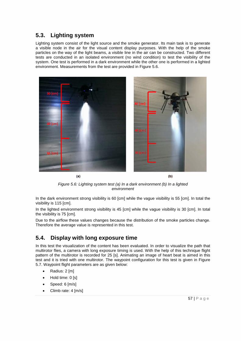
5.3. Lighting system Lighting system consist of the light source and the smoke generator. Its main task is to generate a visible node in the air for the visual content display purposes. With the help of the smoke particles on the way of the light beams, a visible line in the air can be constructed. Two different tests are conducted in an isolated environment (no wind condition) to test the visibility of the system. One test is performed in a dark environment while the other one is performed in a lighted environment. Measurements from the test are provided in Figure 5.6.
Figure 5.6: Lighting system test (a) In a dark environment (b) In a lighted
environment
In the dark environment strong visibility is 60 [cm] while the vague visibility is 55 [cm]. In total the visibility is 115 [cm]. In the lighted environment strong visibility is 45 [cm] while the vague visibility is 30 [cm]. In total the visibility is 75 [cm]. Due to the airflow these values changes because the distribution of the smoke particles change. Therefore the average value is represented in this test.
5.4. Display with long exposure time In this test the visualization of the content has been evaluated. In order to visualize the path that multirotor flies, a camera with long exposure timing is used. With the help of this technique flight pattern of the multirotor is recorded for 25 [s]. Animating an image of heart beat is aimed in this test and it is tried with one multirotor. The waypoint configuration for this test is given in Figure 5.7. Waypoint flight parameters are as given below:
• Radius: 2 [m] • Hold time: 0 [s] • Speed: 6 [m/s] • Climb rate: 4 [m/s]
57 | P a g e

Figure 5.7: Long exposure time test (x = 3 [m])
The resulting image with the light source open (smoke generator closed) is given in Figure 5.8.
Figure 5.8: Long exposure display with light source
The resulting image with the both light source and smoke generator open is given in Figure 5.9.
58 | P a g e
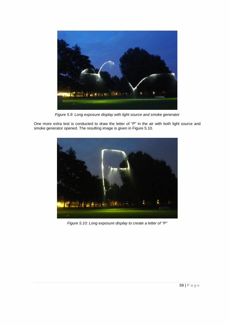
Figure 5.9: Long exposure display with light source and smoke generator
One more extra test is conducted to draw the letter of “P” in the air with both light source and smoke generator opened. The resulting image is given in Figure 5.10.
Figure 5.10: Long exposure display to create a letter of "P"
59 | P a g e

6. Conclusion and future work As a result of the work of this master thesis, the first prototype for flying display system is de-signed and implemented. Depending on the observations from tests and experiments the follow-ing conclusions are made:
• Mikrokopter GPS system has a precision around 2 [m] which gives satisfactory results for the first prototype. However this constraint prevents to track the exact location of the Mikrokopter. Therefore designed paths should be considered with the error rate of 2 [m].
• Mikrokopter platform is able to carry a smoke generator and a light source as a payload. With the extension of these hardware components a visible node in the air is generated for display purposes.
• Mikrokopter firmware is not enough to have a fully autonomous flight. Therefore it is mod-ified for a fully autonomous flight under the supervision of a computer.
• Path finder algorithm is developed to create a route for Mikrokopters for any given shape. Its main purpose is to create a route that satisfies all the connections in the display and that can be looped. Concept relies on Eulerian Cycle theory however this is not enough so it is improved with additional functionalities.
• Management functionalities are developed for the control station to cope with multirotors. These functionalities include the initialization, maintenance and termination of the system execution. Also functionalities to cope with extra ordinary situations (e.g. collisions, low battery etc.) are designed and implemented.
• Graphical user interface is designed and implemented for two main tasks. Firstly, it pro-vides necessary tools to user for the design of the visual content. Secondly, it provides a control screen where the management of the system can be done and the real time tracking of activities can be seen.
• Control strategy and communication protocol between the components are designed and implemented. Since Mikrokopters are communicating with both remote controller and control station, a priority algorithm is developed.
• Flying display system is tested with two Mikrokopters flying simultaneously under the su-pervision of the control station. It can be tested with more multirotors however due to the resources this master thesis work conducted with two quadrotors.
Considering the limited amount of the time and resources this master thesis work has aimed to develop a first prototype for such a system with basic features. Even though the feasibility of such a system is proven with this work, there is still much improvements required on the designed system. Some of these possible improvements can be listed as follow:
• The flying platform can be improved. Mikrokopter is able to do all of the required activities in the air however faster flying platforms can create images of better quality in the air. Although smaller platforms can be faster, it is important to be able to carry a certain amount of payload. A better flying platform satisfying these requirements can be devel-oped.
• The positioning system can be improved. As mentioned before, existing GPS system has approximately 2 [m] of error rate. Other commercially existing GPS systems (e.g. differ-ential GPS, RTK GPS) can give [cm] level accuracy. Researches show that best solution is the RTK GPS module [24] developed by Swift Navigation for UAV usages. It has an accuracy of 4 [cm]. The usage of such a system would allow the usage of higher number of flying devices in the execution since density of GOP is increased.
60 | P a g e

• The graphical user interface can be improved and new functionalities can be added. For example after a visual content is designed system can create an animation to illustrate how the display will look like.
• The path finder algorithm can be improved. With the improvements in the algorithm more complicated 3-dimensional contents can be processed as well. Also it can be optimized to generated paths considering other concerns (e.g. wind, audience position).
Beside the improvements on the designed system, there can be other possible improvements that are required for the success of such a commercial product. Some of these extra features can be listed as follow:
• A secure system can be developed for malicious attacks. System security is important since the execution takes place in public places and malicious attacks can endanger the people around.
• System safety can be increased for the environment. Multirotor platforms can be dangerous when the control is lost. For example they can crash into an audience and may result in injuries. For these kinds of situations new measures can be developed so that system prevents such accidents.
• Autonomous working of the system can be extended. For example the system can be developed such that low battery multirotors are replaced by full battery multirotors autonomously. Also with extra improvement system can be developed to charge the low batter multirotors autonomously and put them into execution when they are ready. Another improvement can be detecting the broken multirotors and separating them.
61 | P a g e

Appendix A - Hardware
A.1 Mikrokopter In this section descriptions for the main hardware components of Mikrokopter are provided. These hardware components are produced by MikroKopter and more detailed information can be found on the Mikrokopter website [16].
A.1.1 FlightCtrl V2.1 board The Mikrokopter FlightCtrl board consists of IMU (Inertia Measurement Unit) and microprocessor board ( A.1).
Figure A.1: Mikrokopter FlightCtrl board [16]
FlightCtrl has a triaxial MEMS accelerometer, gyroscope and barometric pressure. The micropro-cessor is Atmega 1284p processor running at 20 [MHz] which has the embedded software of the FlightCtrl.
This board is capable of altitude control however it is precision is increased with the help of an additional hardware ACC board (Figure A.2). This improvement is necessary to enable Mikrokop-ter to take off and land autonomously.
Figure A.2: Addition of ACC board to FlightCtrl [16]
FlightCtrl has 4 PWM outputs (Figure A.3) with maximum voltage of 5 [V] and maximum current of 100 [mA]. Serial port and SPI are connected to the NaviCtrl. Transistor output is used to con-
62 | P a g e

trol the LEDs (different than the light source) on the Mikrokopter to indicate the status of the copter. Servo3 is used to generate PWM signal for the adjustment of the light intensity of the light source.
Figure A.3: Mikrokopter FlightCtrl connections [16]
A.1.2 NaviCtrl V2.0 board The Mikrokopter NaviCtrl board consists of integrated compass and microprocessor board (Figure A.4).
Figure A.4: Mikrokopter NaviCtrl board [16]
With the combination of the MKGPS board it works as the navigation system for the Mikrokopter. This board enables Mikrokopter to perform following activities:
63 | P a g e

• Waypoint flight: Mikrokopter can follow a route that is determined by the GPS coordi-nated autonomously. This flight can be maintained within the 250 [m] radius around the home position.
• Position Hold: Mikrokopter can maintain its position autonomously. • Come home: Mikrokopter can fly back to its home position autonomously
Its connection channels are illustrated in Figure A.5. Serial port and SPI are connected to the FlightCtrl. Also it has a connection for MKGPS and Wi.232 wireless module.
Figure A.5: Mikrokopter NaviCtrl connections [16]
A.1.3 MKGPS board The Mikrokopter MKGPS board works as the GPS receiver for the Mikrokopter. It has an Ublox GPS receiver and connected directly to the NaviCtrl.
Figure A.6: Mikrokopter MKGPS board [16]
64 | P a g e
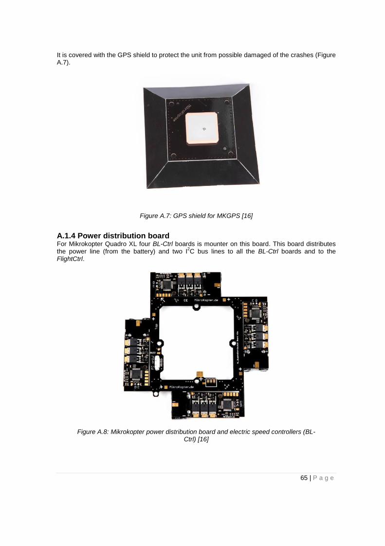
It is covered with the GPS shield to protect the unit from possible damaged of the crashes (Figure A.7).
Figure A.7: GPS shield for MKGPS [16]
A.1.4 Power distribution board For Mikrokopter Quadro XL four BL-Ctrl boards is mounter on this board. This board distributes the power line (from the battery) and two I2C bus lines to all the BL-Ctrl boards and to the FlightCtrl.
Figure A.8: Mikrokopter power distribution board and electric speed controllers (BL-Ctrl) [16]
65 | P a g e

A.1.5 Motors and propellers Four MK3638 brushless motors and EPP1345 CF propellers are used in this configuration of Mikrokopter. Their technical specifications are listed in the Table A.1.
Table A.1: MK3638 brushless motor and EPP1345 CF propeller technical specifications [16]
MK3638 EPP1345 Max Current 20 [A] Diameter 33 [cm] RPM/V 770 [RPM/V] Slope 11.43 [cm] Max Electrical Power 350 [W] Bore 5 [mm] Max Thrust 2200 [g] Weight 100 [g] Dimension 38x35 [mm] Shaft Diameter 4 [mm]
A.2 Control station The control station composed of a computer and a wireless module.
Computer that has been used in this project is Hp EliteBook 840 G1. Technical specifications are given in the Table A.2.
Table A.2: Hp EliteBook 840 G1 technical specifications Hp EliteBook 840 G1
Processor Intel(R) Core(TM) i5-4300 CPU @ 1.90 [GHz] 2.50 [GHz]
RAM 4.00 [GB] Operating system Windows 7 System type 64- Bit operating system
The wireless connection between the control station and the Mikrokopter is established with the Wi.232 V2.0 set which consists of Wi.232 transmitter (connected to the computer at control station) and Wi.232 receiver (connected to the Mikrokopter FlightCtrl). Both modules are already configured to communicate with each other so no additional configuration is necessary.
Wi.232 modules have UART type serial interface that enables the replacement of the wired connection with the transparent UART-to-antenna wireless solution. In this project two Mikrokop-ter is connected to the control station so two Wi.232 (868 [MHz] channel and 904.475 [MHz] Channel) modules are used.
66 | P a g e

Figure A.9: Wi.232 V2.0 set [16]
A.3 Lighting system The lighting system is composed by a LED light source, a smoke generator and additional batter-ies for both.
A.3.1 Light source The light source includes a LED light source, a battery and a light control board.
LEDs and Lenses The Bridgelux high power LEDs [4] are used in this project.
Battery A ZIPPY Flightmax 2200 [mAh] 4S 20C lithium-ion polymer battery has been adopted and its main spesifications are shown in Table A.3 [2].
Table A.3: Light source battery specifications [19]
ZIPPY Flightmax 2200 [mAh] Capacity 2200 [mAh] Voltage 14.8 [V] Cells 4S Max discharge current (constant) 44 [A] Max discharge (burst) 66 [A] Weight 220 [g] Dimensions 101x35x33 [mm] Balance plug JST-XH Discharge plug XT60
Light control board Every high power LED module adopted in the light source installed on-board is controlled by a pulse width modulator (MCP1630). This board generates a high power PWM output (Imax = 700 [mA]) which is used for dimming the LED modules [19]
67 | P a g e
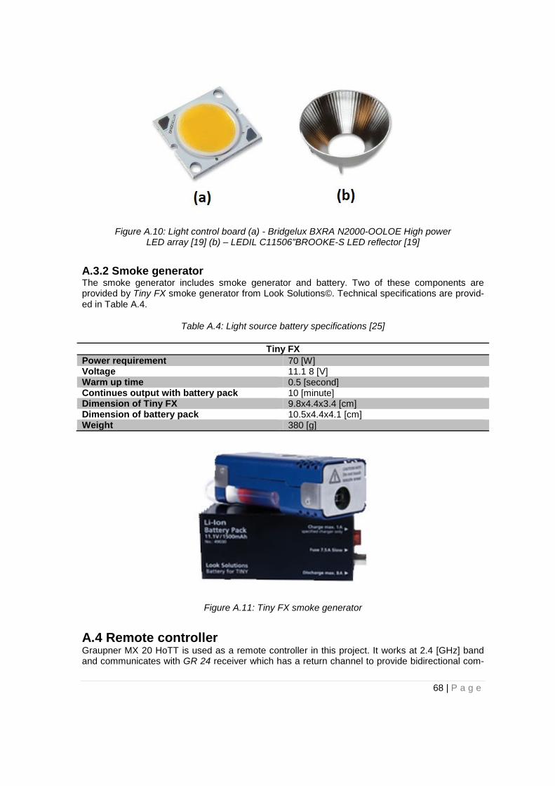
Figure A.10: Light control board (a) - Bridgelux BXRA N2000-OOLOE High power LED array [19] (b) – LEDIL C11506”BROOKE-S LED reflector [19]
A.3.2 Smoke generator The smoke generator includes smoke generator and battery. Two of these components are provided by Tiny FX smoke generator from Look Solutions©. Technical specifications are provid-ed in Table A.4.
Table A.4: Light source battery specifications [25]
Tiny FX Power requirement 70 [W] Voltage 11.1 8 [V] Warm up time 0.5 [second] Continues output with battery pack 10 [minute] Dimension of Tiny FX 9.8x4.4x3.4 [cm] Dimension of battery pack 10.5x4.4x4.1 [cm] Weight 380 [g]
Figure A.11: Tiny FX smoke generator
A.4 Remote controller Graupner MX 20 HoTT is used as a remote controller in this project. It works at 2.4 [GHz] band and communicates with GR 24 receiver which has a return channel to provide bidirectional com-
68 | P a g e

munication.
This remote controller has 12 channels. First four channels are attained to the joystick move-ments (roll, pitch, yaw and gas) but the rest of the channels can be configured. It has 2 joysticks with 360 degree movement capacity, 7 switches and 3 potentiometers. Graupner MX 20 HoTT has a maximum range of 4 [km]
Figure A.12: Graupner MX 20 HoTT remote controller and GR 23 receiver
69 | P a g e

Appendix B - Software
B.1 Control station source files
B.1.1 pc_serial_port.cpp This source file is necessary to initialize and configure the serial port for communicating with Wi.232 wireless module. It has three functions.
init_com_port This function is responsible for the initialization of the serial port. It gets the port number and the device number as the input then initializes the specified port for the specified device. Also it configures dcb (device control block) structure of the COM port to match with FlightCtrl communi-cation configuration.
getCharFromCom This function gets the address of an input buffer and the device number. It is responsible for receiving the data from the COM port specified for the given device number and putting this data into the specified buffer.
sendStringToCom This function gets the address of an output buffer, its length and the device number. It is respon-sible for sending the data of output buffer to the COM port specified for the given device number.
B.1.2 fc_comm.cpp This source file is necessary for the implementation of the communication protocol with the FlightCtrl. It has four functions.
Decode64 This function decodes the received data from the FlightCtrl according to the communication protocol of Mikrokopter.
SendOutData This function encodes the data to be sent to FlightCtrl according to the communication protocol of Mikrokopter. After that it calls the AddCRC function to add parity bit to the package.
AddCRC This function adds parity bit to the end of the package according to the communication protocol of Mikrokopter.
B.1.3 router.cpp This source file is responsible for the path finder algorithm. In this source code path is created, translated into appropriate GPS coordinates and transferred to the Mikrokopter. A classed named Graph is created in this code for the visual content. In this chapter first the functions of the Graph will be explained and then other functions will be documented.
70 | P a g e
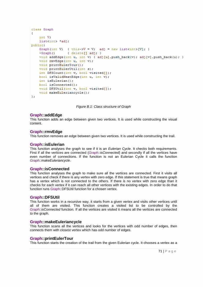
Figure B.1: Class structure of Graph
Graph::addEdge This function adds an edge between given two vertices. It is used while constructing the visual content.
Graph::rmvEdge This function removes an edge between given two vertices. It is used while constructing the trail.
Graph::isEulerian This function analyses the graph to see if it is an Eulerian Cycle. It checks both requirements. First if all the vertices are connected (Graph::isConnected) and secondly if all the vertices have even number of connections. If the function is not an Eulerian Cycle it calls the function Graph::makeEuleriancycle.
Graph::isConnected This function analyses the graph to make sure all the vertices are connected. First it visits all vertices and check if there is any vertex with zero edge. If this statement is true that means graph has a vertex which is not connected to the others. If there is no vertex with zero edge than it checks for each vertex if it can reach all other vertices with the existing edges. In order to do that function runs Graph::DFSUtil function for a chosen vertex.
Graph::DFSUtil This function works in a recursive way, it starts from a given vertex and visits other vertices until all of them are visited. This function creates a visited list to be controlled by the Graph::isConnected function. If all the vertices are visited it means all the vertices are connected to the graph.
Graph::makeEuleriancycle This function scans all the vertices and looks for the vertices with odd number of edges, then connects them with closest vertex which has odd number of edges.
Graph::printEulerTour This function starts the creation of the trail from the given Eulerian cycle. It chooses a vertex as a
71 | P a g e

starting point and calls the function Graph::printEulerUtil. It records the trail in an integer array named destinations in order to be used by other functions.
Graph::printEulerUtil This is a recursive function. It removes an edge and calls itself until all the edges are removed from the graph. While removing the edge important thing is not to remove bridges which would cause disconnection in the graph. For this purpose before removing an edge it calls the function Graph::isValidNextEdge to see if that edge is a bridge.
Graph::isValidNextEdge This function gets two vertices as an input and checks if the edge in between is a bridge. First it checks if that edge is the only connection from the vertex. If that is the case then this edge is not a bridge because it is the only connection. If there are multiple edges from that vertex then this function calls Graph::DFSCount function to count the number of reachable vertices from that vertex. Then it removes the given edge and again calls the Graph::DFSCount function the count the number of reachable edges. If the result of this two is same then given edge is not a bridge so it can be removed. However if the results are different, then it means removing that edge would cause a disconnection in the graph.
Graph::DFSCount This function starts from the given vertex and visits other vertices. It marks the visited vertices and recursively call itself until all the vertices are visited. Every time it visits a new vertex, function increases the counter and at the end sends this value to Graph::isValidNextEdge to be analyzed to see how many vertices are reachable from the vertex.
test This function gets a Graph class as an input and calls the Graph::isEulerian function to see if the given graph is an Eulerian Cycle. If it is not an Eulerian Cycle then this function calls Graph::makeEuleriancycle function to transform the given Graph into Eulerian Cycle.
routing This function receives the trail in the destinations array. This array composes of locations of each vertex to be visited in sequence. Each integer in the array represents a location in the grid of points to be generated in the air for the digital screen. This function calls a sequence of functions (sending_advance_waypoints_default, split_joints, latitude_longtitude_altitude) for each vertex in this array in a loop to generate a data to be uploaded to Mikrokopter. Its main task is to split the vertices with more than two connections and generate an appropriate GPS data for sending Mikrokopter. After the loop is finished it calls sent_data function to upload this data to Mikrokop-ter.
sending_advance_waypoints_default This function determines the default parameters for the waypoint to be sent.
split_joints This function is responsible for the splitting of the vertices with more than two edges. It searches the whole destinations array to find out if the given vertex is visited more than once. If that is the case then it should be split to avoid crashes. For these vertices this function attains a new loca-tion.
latitude_longtitude_altitude This function is responsible for the transformation of the values in the destinations array to actual GPS position data.
72 | P a g e

sent_data This function is responsible for sending the waypoint data to Mikrokopter.
waypoint_drive This function gets a GPS position and a device number as an input. Then it uploads the neces-sary data to the specified device to make it fly to given location. It is used by the go to location function.
land_to_location This function gets a GPS position and a device number as an input. Then it uploads the neces-sary data to the specified device to make it land to given location. It is used by come home and emergency landing functions.
B.1.4 main.cpp This file is responsible for the initialization of the entire control station program and the manage-ment of the system. In this part various functions in this file will be explained.
initialize_port This function calls init_com_port function for each device in the system to initialize the specified COM port for each of them.
routine_checks This function is called periodically to make sure system is working properly. It updates the posi-tion data of each flying device according to the new data received then checks if there is a possi-bility of collision in the system. Then it calls to battery_check function to see if there is low battery warning in any of the flying devices. It also restarts the periodic data sending from the Mikrokop-ter each time for the DebugOut and OSD data.
battery_check This function checks if any of the multirotors has a low battery. If that is the case it either calls the come_home function if the battery level is not so low or calls the emergency_landing function if battery level is critically low. But before calling these functions it checks if there is any other multirotor beneath the flying device. If there is another multirotor then it asks user to move that device to be able to land the one with the low battery.
come_home This function first descends the specified device to a safe altitude then flies it to home location. After reaching to home location device starts landing procedure. This procedure is done with sending a waypoint with -100 altitude and 0.8 climb rate. When Mikrokopter receives these waypoints it lands to given location.
emergancy_landing This function lands the flying device to its current location. In order to do that it uses the GPS data coming from the Mikrokopter and uploads a waypoint with the same GPS position, altitude of-100 and climb rate of 0.8.
arrange_poti This function is responsible for the adjustment of the various parameters (altitude control, GPS control, switching on/off motors, carefree control) of the Mikrokopter.
initialize_process This function makes the necessary arrangements for the initialization of the process (e.g. switch-
73 | P a g e
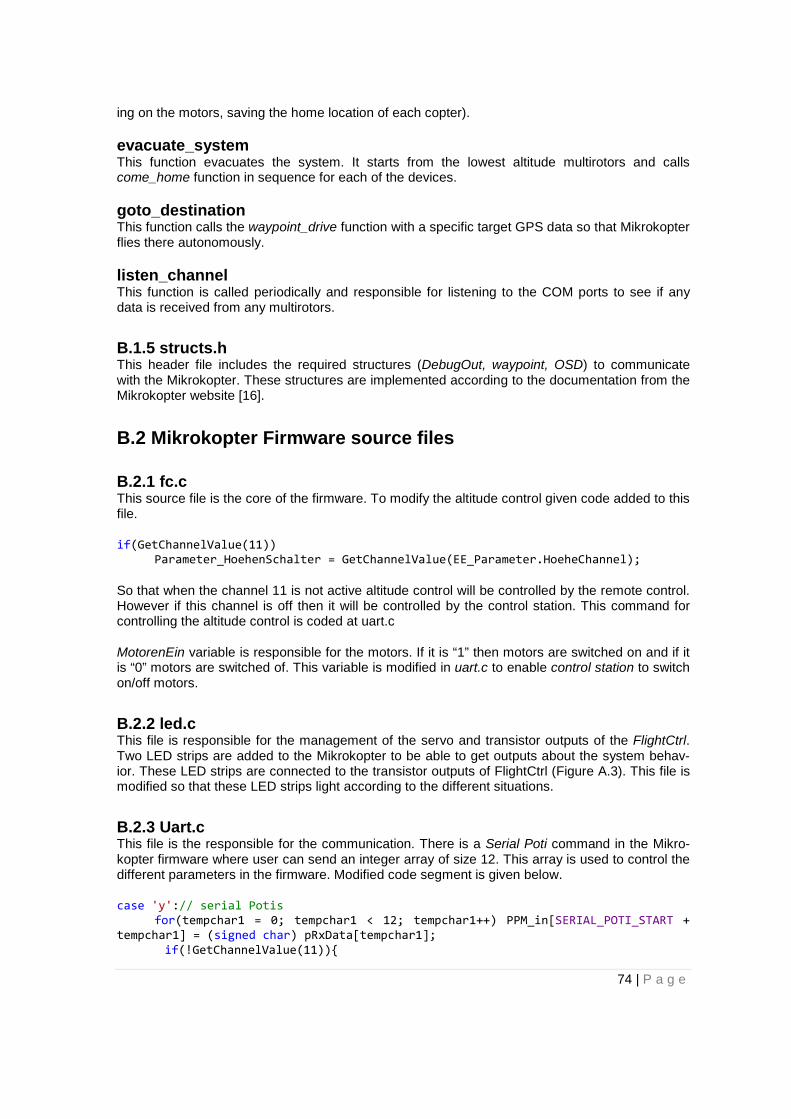
ing on the motors, saving the home location of each copter).
evacuate_system This function evacuates the system. It starts from the lowest altitude multirotors and calls come_home function in sequence for each of the devices.
goto_destination This function calls the waypoint_drive function with a specific target GPS data so that Mikrokopter flies there autonomously.
listen_channel This function is called periodically and responsible for listening to the COM ports to see if any data is received from any multirotors.
B.1.5 structs.h This header file includes the required structures (DebugOut, waypoint, OSD) to communicate with the Mikrokopter. These structures are implemented according to the documentation from the Mikrokopter website [16].
B.2 Mikrokopter Firmware source files
B.2.1 fc.c This source file is the core of the firmware. To modify the altitude control given code added to this file.
if(GetChannelValue(11)) Parameter_HoehenSchalter = GetChannelValue(EE_Parameter.HoeheChannel);
So that when the channel 11 is not active altitude control will be controlled by the remote control. However if this channel is off then it will be controlled by the control station. This command for controlling the altitude control is coded at uart.c
MotorenEin variable is responsible for the motors. If it is “1” then motors are switched on and if it is “0” motors are switched of. This variable is modified in uart.c to enable control station to switch on/off motors.
B.2.2 led.c This file is responsible for the management of the servo and transistor outputs of the FlightCtrl. Two LED strips are added to the Mikrokopter to be able to get outputs about the system behav-ior. These LED strips are connected to the transistor outputs of FlightCtrl (Figure A.3). This file is modified so that these LED strips light according to the different situations.
B.2.3 Uart.c This file is the responsible for the communication. There is a Serial Poti command in the Mikro-kopter firmware where user can send an integer array of size 12. This array is used to control the different parameters in the firmware. Modified code segment is given below.
case 'y':// serial Potis for(tempchar1 = 0; tempchar1 < 12; tempchar1++) PPM_in[SERIAL_POTI_START + tempchar1] = (signed char) pRxData[tempchar1]; if(!GetChannelValue(11)){
74 | P a g e

if(!PPM_in[SERIAL_POTI_START + 5]) Parameter_HoehenSchalter = 0; else if (PPM_in[SERIAL_POTI_START + 5]) Parameter_HoehenSchalter = 200; if(!PPM_in[SERIAL_POTI_START + 8]){ CareFree = 0; } else if(PPM_in[SERIAL_POTI_START + 8]){ CareFree = 1; } Servos = PPM_in[SERIAL_POTI_START + 7]; if (PPM_in[SERIAL_POTI_START + 9] == 1) MotorenEin = 1; else if(PPM_in[SERIAL_POTI_START + 9] == 31) MotorenEin = 0; } Condition of Channel 11 being of is added here so that control station commands will only be valid only if channel 11 is off.
B.2.4 Spi.c This file responsible for communication with the NaviCtrl. GPS control status parameter is deter-mined here so following code modification is conducted in this file.
if(GetChannelValue(11)) ToNaviCtrl.Param.Byte[4] = GetChannelValue(EE_Parameter.NaviGpsModeChannel); else ToNaviCtrl.Param.Byte[4] = PPM_in[SERIAL_POTI_START + 6];
B.2.timer0.c This file is responsible for the management of the servo outputs. In this file servo3 output is used to control the light intensity so following code segment is added to the control
if(!GetChannelValue(11)) RemainingPulse += ((int16_t)Servos * MULTIPLYER) - (256 / 2) * MULTIPLYER; else RemainingPulse += ((int16_t)Parameter_Servo3 * MULTIPLYER) - (256 / 2) * MULTIPLYER;
75 | P a g e
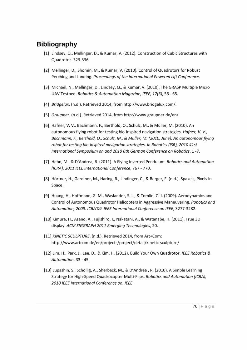
Bibliography [1] Lindsey, Q., Mellinger, D., & Kumar, V. (2012). Construction of Cubic Structures with
Quadrotor. 323-336.
[2] Mellinger, D., Shomin, M., & Kumar, V. (2010). Control of Quadrotors for Robust Perching and Landing. Proceedings of the International Powered Lift Conference.
[3] Michael, N., Mellinger, D., Lindsey, Q., & Kumar, V. (2010). The GRASP Multiple Micro UAV Testbed. Robotics & Automation Magazine, IEEE, 17(3), 56 - 65.
[4] Bridgelux. (n.d.). Retrieved 2014, from http://www.bridgelux.com/.
[5] Graupner. (n.d.). Retrieved 2014, from http://www.graupner.de/en/
[6] Hafner, V. V., Bachmann, F., Berthold, O., Schulz, M., & Müller, M. (2010). An autonomous flying robot for testing bio-inspired navigation strategies. Hafner, V. V., Bachmann, F., Berthold, O., Schulz, M., & Müller, M. (2010, June). An autonomous flying robot for testing bio-inspired navigation strategies. In Robotics (ISR), 2010 41st International Symposium on and 2010 6th German Conference on Robotics, 1 -7.
[7] Hehn, M., & D’Andrea, R. (2011). A Flying Inverted Pendulum. Robotics and Automation (ICRA), 2011 IEEE International Conference, 767 - 770.
[8] Hörtner, H., Gardiner, M., Haring, R., Lindinger, C., & Berger, F. (n.d.). Spaxels, Pixels in Space.
[9] Huang, H., Hoffmann, G. M., Waslander, S. L., & Tomlin, C. J. (2009). Aerodynamics and Control of Autonomous Quadrotor Helicopters in Aggressive Maneuvering. Robotics and Automation, 2009. ICRA'09. IEEE International Conference on IEEE, 3277-3282.
[10] Kimura, H., Asano, A., Fujishiro, I., Nakatani, A., & Watanabe, H. (2011). True 3D display. ACM SIGGRAPH 2011 Emerging Technologies, 20.
[11] KINETIC SCULPTURE. (n.d.). Retrieved 2014, from Art+Com: http://www.artcom.de/en/projects/project/detail/kinetic-sculpture/
[12] Lim, H., Park, J., Lee, D., & Kim, H. (2012). Build Your Own Quadrotor. IEEE Robotics & Automation, 33 - 45.
[13] Lupashin, S., Schollig, A., Sherback, M., & D’Andrea , R. (2010). A Simple Learning Strategy for High-Speed Quadrocopter Multi-Flips. Robotics and Automation (ICRA), 2010 IEEE International Conference on. IEEE.
76 | P a g e

[14] Mahony, R., Kumar, V., & Corke, P. (2012). Multirotor Aerial Vehicles. IEEE Robotics & Automation, 20 - 32.
[15] Mellinger, D., Michael, N., & Kumar, V. (2012). Trajectory generation and control for precise aggressive maneuvers with quadrotors. The International Journal of Robotics Research, 664 - 674.
[16] MikroKopter. (n.d.). Retrieved 2014, from Mikrokopter Wiki: http://www.mikrokopter.de/ucwiki/FrontPage
[17] Muller, M., Lupashin, S., & D’Andrea , R. (2011). Quadrocopter Ball Juggling. Intelligent Robots and Systems (IROS), 2011 IEEE/RSJ International Conference, 5113-5120.
[18] Ocean of Light. (n.d.). Retrieved 2014, from http://www.oceanoflight.net/blog/
[19] Pestrin, A. (2012). Flying lightning systems: Design, imlementation and evaluation study. Universita degli studi di udine.
[20] Pounds, P., Mahony, R., & Corke, P. (2006). Modelling and Control of a Quad-Rotor Robot. Australian Conferance on Robotic and Automation.
[21] Pounds, P., Mahony, R., & Gresham, J. (2004). Towards Dynamically-Favourable Quad-Rotor Aerial Robots. Australasian Conference on Robotics and Automation.
[22] Sa, I., & Corke, P. (2012). System Identification, Estimation and Control for a Cost Effective. IEEE International Conferance on Robotics and Automation, 2202 - 2209.
[23] Santhosh, S., & Sundeep, G. (2014). Aerial vehicle. Retrieved 2014, from vidhyodaya: http://www.vidhyodaya.com/papers/aerial-vehicle-ssanthosh-gsundeep-prince-sri-venkateshwara-college-of-engineering
[24] Swift Navigation. (n.d.). Retrieved 2014, from Piksi: http://swift-nav.com/piksi.html
[25] Tiny FX user manual. (n.d.). Retrieved 2014, from http://looksolutionsusa.com/wp-content/uploads/2013/09/tinyfx_manual.pdf
[26] Vicon. (n.d.). Retrieved 2014, from http://www.vicon.com/
77 | P a g e