Eindhoven University of Technology MASTER … asa High-level Synthesis Language Ernst HendrikMulder,...
122
Eindhoven University of Technology MASTER VHDL as a high-level synthesis language Mulder, E.H. Award date: 1992 Disclaimer This document contains a student thesis (bachelor's or master's), as authored by a student at Eindhoven University of Technology. Student theses are made available in the TU/e repository upon obtaining the required degree. The grade received is not published on the document as presented in the repository. The required complexity or quality of research of student theses may vary by program, and the required minimum study period may vary in duration. General rights Copyright and moral rights for the publications made accessible in the public portal are retained by the authors and/or other copyright owners and it is a condition of accessing publications that users recognise and abide by the legal requirements associated with these rights. • Users may download and print one copy of any publication from the public portal for the purpose of private study or research. • You may not further distribute the material or use it for any profit-making activity or commercial gain Take down policy If you believe that this document breaches copyright please contact us providing details, and we will remove access to the work immediately and investigate your claim. Download date: 17. May. 2018
Transcript of Eindhoven University of Technology MASTER … asa High-level Synthesis Language Ernst HendrikMulder,...

Eindhoven University of Technology
MASTER
VHDL as a high-level synthesis language
Mulder, E.H.
Award date:1992
DisclaimerThis document contains a student thesis (bachelor's or master's), as authored by a student at Eindhoven University of Technology. Studenttheses are made available in the TU/e repository upon obtaining the required degree. The grade received is not published on the documentas presented in the repository. The required complexity or quality of research of student theses may vary by program, and the requiredminimum study period may vary in duration.
General rightsCopyright and moral rights for the publications made accessible in the public portal are retained by the authors and/or other copyright ownersand it is a condition of accessing publications that users recognise and abide by the legal requirements associated with these rights.
• Users may download and print one copy of any publication from the public portal for the purpose of private study or research. • You may not further distribute the material or use it for any profit-making activity or commercial gain
Take down policyIf you believe that this document breaches copyright please contact us providing details, and we will remove access to the work immediatelyand investigate your claim.
Download date: 17. May. 2018

VHDL as aHigh-level Synthesis
LanguageBy E.H. Mulder
Master Thesis

VHDL asaHigh-levelSynthesisLanguage
Ernst Hendrik Mulder,
Eindhoven University of TechnologyDepartment of Electrical EngineeringDesign Automation Section
Master Thesis
performed: September 1991- August 1992by order of prof. dI. ing. J.A.G. Jesssupervised by ir. H.A. Hilderink
Eindhoven, August 1992.

i
AbstractThis thesis discusses the usage of VHDL as a high-level synthesis language for the ESsilicon compiler. The ES silicon compiler is a silicon compilation tooI under development at the Design Automation Section of the Department of Electrical Engineeringof the Eindhoven University of Technology. VHDL is an industrial standard language used for a variety of design tasks [LRM 88] [Lipsett 89] [Ashenden 90].
Because VHDL is an industrial standard, there are many VHDL tools available, andusing VHDL makes crossing the university+-+industry barrier easier.
The ES silicon compiler and the ASCIS data flow graph are introduced [Veen 85][Stok 91] [Eijndhoven 91]. The ASCIS data flow graph is a flow analysis method representing data dependencies. In the ASCIS data flow graph all control flow constructsof an algorithm, as weIl as operations and expressions are represented by data flowoperators. The ES silicon compiler internally uses the ASCIS data flow graph. To beable to use any high-level synthesis language, a translation from it to the ASCIS dataflow graph must be possible.
VHDL is originally a language for describing existing hardware within the context ofan event-driven simulator, and the underlying model and some of the language constructs of VHDL reflect this origin. The ASCIS data flow graph uses a token flowmodel.
The difference between the underlying model of VHDL and the model of the ASCISdata flow graph, constitute the model problem. The model problem together with someuntranslatable language constructs of VHDL constitute the main translation problem.
The model problem is approached from five different angles to find a solution to it.None of these prove to be real solutions, and the model problem stays unsolved.
Apart from language constructs depending on the model problem, and those notsuitable for high-level synthesis, many other VHDL constructs remain and prove tobe translatabIe. In order to become translatabIe, most of these constructs have to bepre-processed. This pre-processing is worked out for many of VHDL's concurrentstatements, sequential statements, and expressions.
The conclusion is that VHDL is currently not usabIe as a high-level synthesis language for the ES silicon compiler, mainly because the model problem has not yetbeen solved. If the model problem were solved, most of VHDL is usabIe.

iii
PrefaceComputer System
(ISO) A functional unit, consisting of one or more computers and associatedsoftware, that uses common storage for all or part ofa program and also for allor part of the data necessary for the execution of the program; executes user-written or user-designated programs; performs user-designated data manipulation,including arithmetic operations and logic operations; and that can executeprograms that modify themselves during their execution. A computer system maybe a stand-alone unit or may consist ofseveral interconnected units. Synonymouswith ADP system, computing system [ANDIPS 82].
The above is taken from a computer dictionary I saved from the dustbin one day.This is only one of the many nice definitions stored therein. It illustrates how hard itis to define certain things in plain text (if ever you come across the work, look up calculator, address and chad). The VHDL language reference manual tries to define manyaspects of VHDL in plain text too.
In my view this is one of the reasons why writing a program that can read VHDL isvery difficuIt. As an example some text on the subject of scope and visibility:
Each selected name in a use clause identifies one or more declarations that willpotentially become directly visible. If the suffix of the selected name is a simplename or operator symbol, then the selected name identifies only the declaration(s) of that simple name or operator symbol contained within the package orlibrary denoted by the prefix of the selected name [LRM 88 § 10.4].
It took me quite some time and exercise to get accustomed to the language used inthe VHDL language reference manual. Even now it still happens that I have to reread a paragraph four times before its meaning becomes dear. I hope this thesis iseasier to read!
I thank the following people for their support: Ric Hilderink, Marc Heijligers andCatheleijne Berck. Thank you: Catheleijne, Ric, and Nico van Arkel for proofreading.Furthermore I thank Jens Brage and Murray Pearson for the many discussions wehad on many VHDL subjects bye-mail.
Ernst Mulder
[email protected]@es.ele.tue.nl
Eindhoven, August 1992.

v
ContentsABSTRACT i
PREFACE iii
CONTENTS v
1 INTRODUCTION 11.1 About The ES silicon compiler 21.2 About VHDL 31.3 About the ASCIS data flow graph 41.3.1 Brief introduction to the ASCIS data flow graph 41.3.2 DFG drawing conventions used in this thesis 7
2 VHDL AND lTS UNDERLYING MODEL2.1 The origin of VHDL 92.2 The structure of a VHDL design 102.3 The elaboration and execution of a VHDL design 142.3.1 The simulation cycle 142.3.2 SignaIs, drivers, buses and resolution functions 152.4 The model problem 182.5 Possible solutions for the model problem 192.5.1 Describing the VHDL model in algorithms 192.5.2 Perform communications using a handshake package 202.5.3 Change the ASCIS data flow graph's definition 212.5.4 Act as if VHDL uses token flow 222.5.5 Realise token flow with VHDL. 222.6 Conclusions 23
3 VHDL AS A HIGH-LEVEL SYNTHESIS LANGUAGE3.1 Introduction 253.2 Which parts of VHDL are not suitable for HLS? 253.3 Suggested structure of a VHDL design for HLS 263.4 ProcVHDL 273.5 Conclusions 28
4 TRANSLATION DECISIONS4.1 Some questions on the subject of translation 294.2 Literalness of the translation 304.3 Restrictions imposed by the data flow graph 304.3.1 Escape-statements 304.3.2 Event-driven statements 314.3.3 Side-effects 324.3.4 Statements without data transfer 334.4 Conclusions 33

vi
5 THE TRANSLATION OF CONCURRENT STATEMENTS5.1 Overview 355.2 Translation techniques .365.2.1 The block statement 365.2.2 The process statement. 385.2.3 The concurrent procedure call.. .425.2.4 The concurrent assert statement. 435.2.5 The concurrent signal assignment statement.. .445.2.6 The component instantiation statement.. .465.2.7 The generate statement. 485.3 Conclusions 50
6 THE TRANSLATION OF SEQUENTIAL STATEMENTS6.1 Overview 536.2 Translation techniques .546.2.1 The if statement 556.2.2 The case statement. 576.2.3 The loop, next and exit statements 616.2.3.1 Loop statements without escape-statements 626.2.3.2 Loop statements with escape-statements 646.2.4 The return statement. 676.2.4.1 The return statement in a procedure body 676.2.4.2 The return statement in a function body 686.2.5 The procedure call statement.. 706.2.6 The signal assignment statement 736.2.7 The variable assignment statement.. 736.2.8 The assert statement. 756.2.9 The wait statement 786.2.10 The null statement. 786.3 Conclusions 80
7 THE TRANSLATION OF DATA TYPES AND EXPRESSIONS7.1 VHDL Data Types 837.2 VHDL Expressions 857.2.1 VHDL operators 857.2.2 VHDL operands 937.2.2.1 Names 947.2.2.2 Literals 947.2.2.3 Aggregates 957.2.2.4 Function calls 957.2.2.5 Qualified expressions 957.2.2.6 Type conversions 957.2.2.7 Allocators 967.3 Conclusions 96
8 OTHER TRANSLATION ISSUES8.1 Overloading 978.1.1 Subprogram overloading 978.1.2 Enumeration literal overloading 998.2 Recursion 998.2.1 Recursion in subprograms 998.2.2 Recursion in structural descriptions 1008.3 Conclusions 100

CONTENT5 Vll
9 THE IMPLEMENTATION OF THE TRANSLATOR9.1 Choosing the right tools 1019.2 The definition of data structures 1029.3 The structure of the program 1039.4 Future enhancements 1049.5 Conclusions 104
CONCLUSIONS 105
BIBLIOGRAPHY 107
COMMON ABBREVIATIONS 109
LIST OF ILLUSTRATIONS 111
INDEX 115
APPENDIX A HANDSHAKE PACKAGE. 117
APPENDIX B A LIST OF SOURCE FILES 119

1
Chapter 1Introduction
The Design Automation Section of the Department of Electrical Engineering of theEindhoven University of Technology (ES) develops tools for the design of integratedcircuits. One of these tools is a silicon compiler, which translates an abstract behavioural specification of a digital system into a hardware realisation on silicon. Suchan abstract behavioural specification -in most cases an algorithm- is usually specified in a high-level synthesis language.
At the moment the high-level synthesis languages Silage [Hilfinger 84], ELLA[Morisson 94] and HardwareC [Ku 90] are the source languages of many high-levelsynthesis systems. Another possible high-level synthesis language is VHDL. Thislanguage is rapidly growing to be an industrial standard for many levels of hardwaredescription, including high-level behavioural description.
The high-level synthesis part of the ES silicon compiler internally uses the ASCIS dataflow graph (DFG) as the central object. High-level synthesis is the first step in siliconcompilation. This requires a translation step between VHDL and the ASCIS data flowgraph.
This thesis studies whether VHDL can be used as a high-level synthesis language incombination with the ES silicon compiler. To be able to understand some of the chapters in this thesis, more than just familiarity with VHDL and the ASCIS data flowgraph is a necessity. The two standard references on these two subjects are [LRM 88]and [Eijndhoven 91].
In the remainder of this introduction, section 1.1 gives a more detailed description ofthe ES silicon compiler, section 1.2 contains more details on VHDL, and finally section 1.3 describes the ASCIS data flow graph.

2 CHAPTER 1
1.1 About The ES silicon compiler...
The ES silicon compiler is a tooI that generates a layout of a chip from a functionaldescription the user provides. The silicon compiler consists of several parts, given infigure 1.1. High-level synthesis is the first step of silicon compilation. Here the behavioural description describing how the chip should interact with its environment,together with user-specified goals and constraints, are synthesised into a data pathand a controller for it. The data path describes a network of functional units, foreground memory (registers), background memory (RAM and ROM) and their interconnect; the controller, specified by a finite state machine (FSM) controls the datapath [Arts 91 p. 1].
Behaviouraldescription
Data path
IGoals andconstraints
Controller
Figure 1.1: Silicon compiler overview
The high-level synthesis process is dividable into subparts as given in figure 1.2[Arts 91 p. 5]. A DFG constructor translates the syntax tree of the description specified by the input language into an ASCIS data flow graph (see § 1.3). The resultingdata flow graph is the centraI object used in the high-level synthesis system. All synthesis operations (scheduling, preselection, optimisation, ... ) perform their tasksupon the data flow grapht . As the last part of high-level synthesis the extractor creates a data path and controller out of the data flow graph.
It is possible to use more than one input language, as long as there is a mapping tothe ASCIS data flow graph.
t It actually uses three different graphs, the data flow graph, the network graph and the contralgraph. The data flow graph is an input to the high level synthesis process. During the process, thevarious tasks generate the other two graphs.

INTRODUCTION 3
IvParser
Otlzerdescriptionlanguage(s)VHDL I
v___P_a-,r_s_e_r__JAbstractsyntax tree
module generation,preselection, library,optimisation,scheduling, allocation, ...
p---·---I
I
1Extractor~
Data patlz 1 1Controller
ASCISdata flow graplz
Figure 1.2: High-level synthesis overview
In the ideal case, a parser translates the high-level description into an abstract syntaxtree, which the DFG constructor then translates into an ASCIS data flow graph. In thereaI world however it is more convenient to do both steps separately for all input languages. Thus a single tooI will translate VHDL descriptions into a syntax tree andthen into an ASCIS data flow graph.
1.2 About VHDL...
VHDL is the abbreviation of "VHSIC Hardware Description Language". VHSIC isthe abbreviation of "Very High Speed Integrated Circuits", a Program Office of theDepartment of Defence of the United States of America.
VHDL is designed for describing existing hardware within the context of anevent-driven simulator but it is also possible to use it for designing new hardware.
The scope of VHDL covers the description of architectural description to gate leveldescription. The language is of a hierarchical nature and supports mixed-level simulations [Lipsett 89 p. xii]. VHDL allows description of the structure of a design, thespecification of the function of designs using familiar programming language formsand allows to simulate a design before manufacturing [Ashenden 90].

4 CHAPTER 1
Nowadays, more and more people use VHDL as a design language, a language to design and simulate a circuit in development. A major advantage of VHDL is that it hasbecome an industrial standard; this means that there are a lot of publicly and commercially available tools that support VHDL, and that designs become exchangeable.And last but not least, being able to support VHDL impresses other people and research institutes.
"Choosing an industry standard language makes i teasier to overcome theuniversity+--+industry barrier. Creating synthesis tools is just part of the job; the other part isto convince the industry to use them [Brage 91 p. 2]."
1.3 About the ASCIS data flow graph...
1.3.1 Brief introduction to the ASCIS data flow graph
The data flow graph, defined by Leon Stok in [Stok 91 p. 32] is derived from the demandgraph defined by Arthur Veen in [Veen 85]. The demand graph is a flow analysismethod representing data dependencies. The demand graph can be derived from thesyntax tree of the souree text of an algorithm [Veen 85 p. 70]. The data flow graph canbe derived from the demand graph by inverting the directions of all edges t . TheASCIS data flow graph, formally described in [Eijndhoven 91] is a standardisation effort of the data flow graph.
In this document, the abbreviation DFG denotes the ASCIS data flow graphunless explicitly stated otherwise.
In some places this thesis refers to demand graphs in [Veen 85]; changingthe direction of the edges of the demand graph to get a data flow graph isleft to the reader.
In the DFG all control flow constructs of an algorithm, as well as operations and expressions, are represented by data flow operators. These operators are represented bynodes in the DFG. Directed edges between these nodes define the data flow. The DFGbears close resemblance to petri nets: a node may execute when there is a token on allof its inputs, and tokens may queue when the node where they arrive can not execute, resulting in edges with multiple tokens.
Consider the simpIe assignment expression x =a + b - c. Figure 1.3 shows the corresponding DFG [Arts 91 p. 9]. There are three incoming data edges, containing the values of a, band c. There is one outgoing data edge, containing the value of the assignment operation. There are two nodes, denoting the operations + and-.
t In the dernand graph, the edges point to the previous definition of the value of a variabie; in thedata flow graph they depict the direction of the flow of the value of a variabie.

INTRODUCTION
a \0f' cilef! + rig~t
out
lef! _ right
X ~out
Figure 1.3: A simple data flow graph
5
Every DFG edge is connected to a node by a port. Ports are needed to distinguish between the various input and output edges. Every DFG node must have at least oneinput node and one output node+ . There exist a variety of node types. The followinglist briefly explains them. The list is an adapted and enhanced version of the onelisted in [Arts 91 p. 10].
Operation nodes Nodes with an operator, such as arithmetic and Booleanoperations.
Input and output nodes Nodes of type input are the only nodes without inputedges, and nodes with type output are the only nodeswithout output edges. To execute a graph, one single token must be available on each input node. If the graphwould be instantiated elsewhere as an operation, thenthe names of these input and output nodes define theport names of the operation node.
Constant nodes These nodes generate a token with a predefined constant value at their output when a token is available attheir only input port. The edge of this port is a sourceedge.
Branch and merge nodes A branch node has two incoming edges (a data edge anda contral edge), and has two or more output ports. Abranch node passes the token from the incoming dataedge to the output port selected by the value of the token on the contral edge. An output port must be presentfor every possible selection value, but it is not necessaryto connect an edge to all output ports of the branch node.The merge node is dual to the branch node. These twonodes are necessary to build conditional structures.
Attached to each branch node is a selection list, which isan ordered list associating mutually exclusive valueswith one of the outgoing ports of the branch node[Eijndhoven 91 § 2.5].
+ The input and output nodes are the onIy exceptions to this ruie.

6
Entry and exit nodes
Get and put nodes
Array nodes
CHAPTER 1
The entry and exit nodes are functionally identical to themerge and branch nodes respectively, with one exception: the control input of the entry node initially holds atoken with value O. These nodes are used to build loopconstructs.
Get and put nodes are to provide a mechanism for communication with the environment. They are linked in sequential chains which specify the order of read andwrite operations.
For the operations on one dimensional arrays, three special nodes (initialisation, retrieve and update nodes) areprovided. See also [Eijndhoven 91 p. 11].
There are five different types of edges. The following list briefly explains them. Thislist is adapted from [Arts 91 p. 11].
Data edges
Contro1 edges
Chain edges
Souree edges
Timing edges
These edges transfer tokens which contain data values.
These edges are connected to the control inputs of branch andmerge and entry and exit nodes. Actually, a control edge is thesame as a data edge. The reason why the control edge is distinguished is that this has certain advantages for some high-level synthesis tasks.
These edges are used to serially link all get and put nodes that operate on a single physical external communication port. Furthermore, chain edges are used to link array operations.
These edges are needed to enable constant nodes.
These edges are used to enforce a required timing or execution ordering on the nodes in the DFG.
In the example that is shown in figure 1.4, most of these node and edge types areused. Section 1.3.2 defines the drawing conventions used for drawing ASCIS dataflow graphs in this thesis.

INTRODUCTION 7
G- chain". edge
controledge
source"- __ edge
o
dataedge
ME
BR
y
x = get 0;y =get 0;if (x == 3)
x =5;else
y = 7;put (y);put (x);
exarnple 0int x, y;
}
Figure 1.4: A data flow graph exarnple
1.3.2 DFG drawing conventions used in this thesis
The following drawing conventions for data flow graphs are used in this thesis. To beable to distinguish the different types of edges, one occurrence of every differentedge type is narned in all DFG pictures in this thesis.
plain 0 sourcenode edge
a subgraph 0 chainedge
b,,"ch-,"d- ~:c-~I
controlIII
merge nodes . ME edges ,--I
i
entry-and-
~ ~data
~exit nodes edge
Figure 1.5: Drawing conventions for the ASCIS data flow graph

9
Chapter 2VHDL and its
Underlying ModelThis chapter describes the structure and the underlying model of a design in VHDL,and poses the question whether this structure and this model can be used within theES silicon compiler. The model difference between VHDL and the ASCIS data flowgraph will emerge to be the main problem of this thesis. This chapter addresses thisproblem, and tries to find a solution for it.
Section 2.1 provides a small introduction describing the nature and origin of VHDL.Section 2.2 describes the structure of a VHDL design. Section 2.3 treats the elaboration and execution of a VHDL design, especially the way VHDL handles signais. Section 2.4 defines the model problem; a collection of differences between VHDL and theASCIS data flow graph, causing translation difficulties when translating from theformer into the latter. Section 2.5 tries to find a solution to the model problem, butnone are found. Section 2.6 contains the conclusions to this chapter.
2.1 The origin of VHDL
VHDL is originally a language for describing and simulating existing hardwarewithin the context of an event-driven simulator. As a result of this, the underlyingmodel of VHDL, and some language constructs of VHDL are based on this origin+.
It is possible to use VHDL to design circuits on a low level. The underlying model ofVHDL is very close to the behaviour of digitallogic and other low level hardware.
In high-level synthesis languages, a high degree of abstraction is necessary. A hardware description language used for high-level synthesis should not be based on anyhardware model.
VHDL, however, is based on a hardware model. This makes using VHDL as a highlevel synthesis language difficult.
+ The syntax of certain VHDL constructs are either directly taken from Adat or resembie those of Ada[LRM 88 Pr~face].
t Ada is a trademark of the US DoD.

10 CHAPTER2
2.2 The structure of a VHDL design
A VHDL design file consists of one or more design units. Each design unit can specify a primary or a secondary unit (a body). A context clause defines the context(libraries, packages) which the following unit inherits. Figure 2.1 visualises thishierarchy.
/\~---I
vV
behaviour(processes)or structure(components)
Figure 2.1: The contents of a design unitt
A primary unit is a unit of declaration, and a secondary unit is a unit of specification.
An entity declaration declares a design entity. An architecture body specifies thebody of the corresponding entity. This may be a description of behaviour (algorithm)or of structure (component instantiations and interconnect signaIs). Table 2.1 at theend of this section shows the declarations available in these units.
A configuration declaration specifies a binding of component instantiations with design entities. If a structural description refers to a certain component, a configurationdeclaration can be used to bind this component to a predefined entity defining thecomponent's structure or behaviour.
Finally, a package declaration bundIes a collection of declarations and subroutineswhich are usabIe in multiple design entities by means of a context clause. A packagebody specifies the algorithms of the subprograms the package declaration declares.Table 2.2 at the end of this section shows the declarations available in these units.
t The '/\' sign in a block denotes that all its sub-blocks have to be present (and), the 'v' sign in a blockdenotes that one and only one of its sub-blocks has to be present (exclusive or).

VHDL AND lTS UNDERLYlNG MODEL 11
Figure 2.2 illustrates a description of structure; a structural description specifies thecomponent instantiations out of which a design entity consists, and specifies the interconnecting signals between the porls of these components. Figure 2.3 illustrates adescription of behaviour; a behavioural description specifies an algorithm definingthe behaviour of a design entity.
~LV
component instances ports signals
Figure 2.2: Example of a description of structuret
IIQSl F .~I s3D .- .- + *D S2II
Figure 2.3: Example of a description of behaviour
Behavioural and structural descriptions use the same library units, an entity declaration and an architecture body. The difference is the contents of the architecture body.Figure 2.4 illustrates this.
component instantiationsand mterconnect,describing structure
processes, describin~the behaviour of entIties
Figure 2.4: Describing structure and behaviour
t Aconfiguration declaration may bind component instances to design entities describing their structure or behaviour.

12 CHAPTER2
A structural description usually is of a lower level. At this level it is possible to connect logical ports, like ands and ors. A behavioural description usually is of a higherlevel; at this level it is possible to describe the behaviour of a design entity usingalgorithms.
The above is usually true, but VHDL does not enforce this scheme. It is perfectly possible to create a design at the level of logical ports, and use behavioural specificationsof these ports for the sole purpose of simulation. It is also possible to partitionise adesign into sub-blocks (component instantiations), and to bind these sub-blocks to algorithms (design entities with a behavioural description).
Figure 2.5 shows a simple VHDL design example containing one design entity with abehavioural description, and a simpIe package declaration containing one subtypedeclaration used by the design entity.
package Types issubtype Data is INTEGER;
end Types;
use Work.Types. all;entity HalCAdder is
port ( InpuC1: Data;Inpuc2: Data;Sum: out Data;Carry: out Data );
end Half_Adder;
use Work.Types. all;architecture HalCAdder_Behaviour of HalCAdder isbegin
process (InpuC1, InpuC2)begin
Sum <= InpuC1 xor Inpuc2 after 5 ns;Carry <= Inpuc1 and InpuC2 after 5 ns;
end process ;end HaICAdder_Behaviour;
Figure 2.5: A simpIe VHDL design example
In a high-level synthesis system designs are specified using algorithms. It is a logicaldecision to use behavioural descriptions in VHDL when using VHDL as a high-levelsynthesis language.
In the ideal case, a (high-level) synthesis system will use VHDL behavioural descriptions as its input, use mixed-level VHDL descriptions in its intermediate stages, anduse structural VHDL as its output, specifying library components and theirinterconnect.

VHDL AND lTS UNDERLYlNG MODEL 13
The following sections in this chapter show that the underlying model of VHDLmakes the first stage of this scenario difficuit or even impossible for the ES siliconcompiler and other high-level synthesis systems based on data flow graphs.
Table 2.1: Declarations available in an entity, and an architecture
allowed ••••not allowed i. ..
i..·•·.·• ............lllg~~II.li.~:i~~··i ti.I•••i.••=i.••••
i.••:i1 ...
••••••••••iil.•)
•••/.•
type declarationsubtype declarationconstant declaration
file declarationalias declaration
subprogram declarationuse clause
signal declarationsubprogram body
attribute declarationattribute specification
disconnection specificationcomponent declaration
configuration specificationvariabie declaration
Basic declarations
Other declarations
Table 2.2: Declarations available in a package and its body
::::::
Basic declarations type declaration ï'subtype declaration i ..
cons:f:E i:~I:~:~!E ;:subprogram declaration •••••
use clauselOther declarations
signal declarationsubprogram body
attribute declarationattribute specification
disconnection specificationcomponent declaration
configuration specificationvariabie declaration
ti•... i1..
••••iilallowed •
not allowed

14
2.3
2.3.1
The elaboration and execution of a VHDL design
The simulation cyele
CHAPTER2
The basic form of a VHDL description consists of concurrently running processes,containing sequential programs describing behaviour, and signals by means of whichthe processes communicate.
According to the VHDL model, all processes are running in parallel. These processesassign new values to the signaIs in the description.
A VHDL process executes continuously; after executing its last sequential statement,execution continues at its first statement. A wait statement can suspend a process. If aprocess statement has a sensitivity list, this list implicitly defines a wait statement(see § 5.2.2).
The execution of a VHDL description consists of an initialisation phase followed bythe repetitive execution of its process statements. In each cyele, the simulator computes the values of all signals in the description. If, as a result of this computation anevent occurs on a given signaI, process statements that are sensitive to that signal willresume and will be executed as part of the simulation cyele [LRM 88 § 12.6.3].
I Start simulation!
Increase simulationtime
l Execute all processes I
1~I:'"~simulation I
Figure 2.6: The simulation cyele of VHDL
The following section describes how the signals are updated, and what kind of signalassignment and signal resolution techniques are possible in VHDL.

VHDL AND lTS UNDERLYlNG MODEL 15
2.3.2 SignaIs, drivers, buses and resolution functions
Communication between VHDL entities happens by means of signais. SignaIs are described by a projected output waveform. This is a list of transactions describing the future values of the signa1 by means of time-value pairs (T, v), called transactions in[LRM 88]. The examples in this section are taken and adapted from[Ashenden 90 § 4.1]. The container for a projected output waveform is called a driver.
A driver always contains at least one transaction. The initial contents of a driver associated with a given signal is defined by the default value associated with the signal[LRM 88 § 9.2.1].
A driver can contain a null transaction only. Such an transaction indicates that thedriver is currently turned off (disconnected). A disconnection specification specifiesthe time it takes for a driver to turn oft. An expression of the type BOOLEAN mayguard a signal; it controls whether the signal's driver is to be turned on or oft. Such asignal is called a guarded signal. A bus is one kind of guarded signa!. A bus floats to auser-specified value when all of its drivers are turned off [LRM 88 § 4.3.3, § 4.3.1.2,p. B-2].
Disconnection, buses and guarded signals are available for creating a dynamic testand simulation environment.
Signal assignments are relative to the current simulation time. The assignments <= '0' after 32 ns at simulation time 10 ns produces a time-value pair (l0 + 32, 0).Figure 2.7 illustrates this.
Current time:
Signal assignment:
Resulting projectedwaveform:
lOns
S <= '0' after 32 ns;
~n-Figure 2.7: SimpIe signal assignment
If the simulation time reaches the time 42 ns, this transaction will be processed, andsignal 's' will be updated. If any process is sensitive to signal 's', and its new valuediffers from its previous value, these processes resume execution.
It is possible to do multiple signal assignments in one signa1assignment statement.Figure 2.8 shows an example of such an assignment, producing a projected outputwaveform with two transactions.

16
Current time:
Signal assignment:
Resulting projectedwaveform:
10 ns
S <= 'I' after 4 ns, 'a' after 8 ns;
~'.•.tr.•.•.•.•.•.•.•.•.·•..;4':H.~.·.·.·.·.·.·.·.·.· .•... ~';+~."X.. 1 ;0
CHAPTER2
Figure 2.8: Multiple signal assignrnents in one statement
VHDL knows two types of signal assignments. One with inertial delay, and one withtransport delay. The signal assignment statement assumes inertial delay by default, tospecify transport delay, the signal assignment must include the keyword transport.
This distinction is important when the projected output waveform of a signal is notempty prior to a signal assignment statement. The difference between the two formsof delay is defined as follows.
inertial delay
transport delay
This form of delay is used to model devices which do not respond to input pulses shorter than their output delay.
If a signal assignment with inertial delay occurs, all transactionswith a time later than the time of the new transaction are removed. The new transaction is added. All old transactionsscheduled to occur before the new transaction are deleted up toand including the last one with a different value than the newtransaction.
One might say that 's <= 2 after 2 ns' means "signal 's' musthave the value 2 for at least 2 ns" [Lipsett 89 p. 79].
Transport delay is more straightforward. It specifies that atransaction should occur after a certain amount of delay.
If a signal assignment with transport delay occurs, all transactions with a time later than the time of the new transaction areremoved.
The exact purpose of inertial delay is not clearly defined. According to[Lipsett 89 p. 78] "Inertial delay is a little trickier to understand because its effect onthe driver of a signaI is harder to understand at first glance." which, in my view, is anunderstatement. The definition of the mechanism of inertial delay found in[Lipsett 89 p. 78], [Ashenden 90 § 4.1] and [LRM 88 § 8.3.1] are all different. This thesis uses atenser version of the definition described in [Ashenden 90], now matchingthe [LRM 88] version.
Figure 2.9 shows an example of a signal assignment statement with inertial delay.Figure 2.10 shows an example of transport delay.

VHDL AND lTS UNDERLYlNG MODEL 17
Current time: 5 ns
Previous projectedwaveform: C>
SignaI assignment: S <= '1' after 20 ns;
Resulting projectedwaveform:
Figure 2.9: Modifying an existing projected waveform, inertial delayt
Current time: 10 ns
Previous projectedwaveform:
~
14 ns 18 ns
1 0
Signal assignment:
Resulting projectedwaveform:
S <= transport 'Z' after 6 ns;
··1~;:11·~!i:I~Figure 2.10: Modifying an existing projected waveform, transport delay
VHDL allows multiple sources for a signal. Figure 2.11 shows a structural descriptionwhere this is the case. To determine the value of the resulting signaI, VHDL uses resolution functions.
This signal is driven bymultiple output ports. Insuch a case aresolutionfunction is necessary.
IEl
Ir
I
~.... i:[J F2
I IEl \>.
.ËJ F3 EJ-,-----I I
I................. EJi
El1
Figure 2.11: The necessity of resolution functions
t In a multiple signal assignment with inertial delay, only the first element has inertial delay. The remaining elements implicitly have transport delay.

18 CHAPTER2
Using resolution functions it is, for example, possible to describe tri-state logic. If twotri-state signaIs drive a given signal, the resolution function has to implement thetruth tabIe of table 2.3.
Table 2.3: Truth tabIe for tri-state logict
Input Output
1 1 fail1 0 fail1 Z 1o 1 failo 0 failo Z 0Z 1 1Z 0 0Z Z Z
2.4 The model problem
There are two parts of the VHDL model which prove to be a problem when VHDL isused in a high-level synthesis environment. These are the VHDL execution model,which defines the execution of processes using an event-driven mechanism, and thesignal model defining the behaviour of signais.
Both of these problems are heavily interconnected, and are inherited from the originof VHDL; a language for describing hardware within the context of an event-drivensimulator.
Other chapters in this thesis refer to The model problem. Actually, the modelproblem is not one, but a collection of related and heavily intertwinedproblems.
To be able to understand the nature of these problems, the following list gives a shortdescription of the two problems, and related sub-problems.
• VHDL is event-driven, whilst the DFG is based on token flow.
Processes in VHDL are executed if one of the signals they are sensitive forchanges value. This value change is called an event. In the DFG however, nodesand sub-graphs are executed when there is a value (called taken) available on alltheir inputs.
t 'faH' in this table means an assertion failure. If more than one tri-state driver is active simultaneously, this indicates a design flaw.

VHDL AND lTS UNDERLYlNG MODEL 19
• In VHDL, signal assignments have a time element, whilst the DFG has no noticeof time.
Signal assignments in VHDL can assign a complex projected output waveform toa signal, determining the future behaviour of the signal. Using timing edges it ispossible to introduce a notice of time in the DFG, but this is not sufficient to handle the complex signal assignments of VHDL.
• VHDL uses a simulation cycle. The DFG does not.
In the simulation cycle, one step is reserved to increase the simulation time, andto recalculate the values of all signals at the moment of the new simulation time,using the projected output waveform.
2.5 Possible solutions for the model problem
2.5.1 Describing the VHDL model in algorithms
There exist VHDL simulators. Therefore it is possible to simulate a VHDL design using an algorithmic language. It is even possible to catch the simulation cycle and thebehaviour of VHDL signals in a complex algorithmic program, which in turn is translatabie to a DFG.
Using this technique it is possible to translate any VHDL design into DFGs. However,there will be a massive translation overhead, because the DFGs have to implement asimulation of VHDL.
The result of this is that even a very small VHDL design will result in a massive DFG,and therefore in a massive circuit at the end of the synthesis process. Even apart fromthe fact that this technique is very difficult to implement, this approach is clearly notusabie. Table 2.4 shows the main characteristics of this approach.
Table 2.4: Describing the VHDL model in algorithms
Advantages
• No restrictions are put on the VHDLdesigns.
• Unchanged semantics.
Disadvantages
• Even a very simple VHDL designresults in a massive DFG.
• The translation overhead is very big.
• Very difficult to implement.

20
2.5.2 Perform communications using a handshake package
CHAPTER2
Using the VHDL language construct called a package, it is possible to bundie a set oftypes and subprograms. All communication between different VHDL processes hasto take place using the subprograms in this handshake package.
The communication protocol implemented by the handshake package has to be implementable by the DFG, but the package itself does not in itself have to be translatabie. This way it is still possible to simulate the VHDL design. The VHDL design istranslatabie to a DFG, because the translator recognises the handshake package, andtranslates its protocol, not its contents.
Unfortunately, this technique puts many restrictions on the VHDL text. All communications normally taking place using signais, now have to use the handshakepackage. This means that the usage of signals is restricted to the handshake package.In addition this means that existing VHDL texts have to be rewritten completely before they can be translated.
Concurrent VHDL statements can only communicate using signais. As a result ofthis, this method restricts the usage of concurrent statements. The subprograms in thehandshake package contains sequential statements and can itself only be called bysequential statements. The only place, apart from a subprogram body, where sequential statements are allowed is the concurrent process statement.
This method restricts the usage of concurrent statement to process statements communicating with each other using the handshake package. Other concurrent statements are allowed only when they do not make use of signais.
Among the drawbacks of this method is the fact that it may be difficuit to test for thepresence of the (proper) handshake package.
Appendix A shows a possible handshake package, written by Jens P. Brage of theTechnical University of Denmark. Table 2.5 shows the main characteristics of thehandshake package approach.
Table 2.5: Perform communications using a handshake package
Advantages
• Easy to implement.
• Unchanged semantics.
Disadvantage
• This puts quite a restriction on theVHDL designs.
• To be able to use them, existing VHDLdesigns have to be rewritten conformthe cornrnunication protocol.
• VHDL designs need to be tested on thepresence of the handshake package.
• Restricts the usage of signals in VHDL.

VHDL AND lTS UNDERLYlNCMODEL 21
2.5.3 Change the ASCIS data flow graph's definition
A possible solution for the model problem is to change the definition of the ASCISdata flow graph in such a way that it matches the signal and event behaviour ofVHDL. The new data flow graph should have new operation node types which arelevel sensitivet . Furthermore, new edge types would have to be abIe to act conformthe behaviour of signals in VHDL (see § 2.3.2).
Using these new node and edge types it is possible to get the same behaviour as thesimulation cycle of VHDL. But the new edge type specifically causes this new graphdefinition to differ from the definition of a data flow graph: within the signal modelof VHDL, it is possible to delete events (see § 2.3.2 figure 2.9) which is impossible in atrue data flow graph.
The ASCIS data flow graph is a standard definition and a true data flow graph. It isunwise to change its definition weakening its data flow graph nature. In addition thenew node types sensitive to events would confuse people writing tools that use theASCIS data flow graph, and would make these tools more difficult -if not impossible- to write.
Jens Brage uses a data flow graph definition which differs from the ASCIS data flowgraph, and which is able to detect events to be able to translate his VHDL subsetPro cVHD L into data flow graphs [Brage 91] (see also § 3.4).
Table 2.6 shows the main characteristics of the new data flow graph approach.
Table 2.6: Change the ASCIS data flow graph's definition
Advantages
• No restrictions are put on the VHDLdesigns.
• Unchanged semantics.
Disadvantages
• The ASCIS data flow graph standardhas to change.
• All existing tools using the ASCIS dataflow graph have to be rewritten.
t These nodes also need to remember the last token sent on each input port. These values are requiredif the node is to execute when an event occurs on one of its inputs.

22
2.5.4 Act as if VHDL uses token flow
CHAPTER2
This approach simply ignores the model problem. It treats signals the same as variables; a signal assignment would be the same as a variabie assignment, and timing information in signal assignments are ignored.
This approach has one main disadvantage: the translator changes the behaviour ofthe VHDL design. If the VHDL design is simulated using a VHDL simulation tooI, itsbehaviour would differ from that of its DFG translation.
This change of behaviour is unacceptable, it causes many problems, and eliminatesthe advantage of using VHDL: the availability of simulators and other tools.
Unfortunately, this approach is used by a lot of synthesis tools available at the moment. Mainly because VHDL inherits its event driven model from it originally beinga low level hardware description language, which is taken as an excuse to change thesemantics of VHDL when it is used for high-level synthesis. Table 2.7 shows the maincharacteristics of this approach.
Table 2.7: Act as if VHDL uses token flow
Advantages
• Extremely easy to implement.
• No restrictions are put on the VHDLdesigns.
Disadvantage
• Changed semantics: The behaviour ofthe VHDL design, if sirnulated, differsfrom the behaviour of the resultingDFG.
2.5.5 Realise token flow with VHDL
It is possible to implement data flow graphs in VHDL [Madsen 90]. Using similartechniques it is possible to implement the ASCIS data flow graph in VHDL.
The VHDL source now represents the DFG itself; translating from the VHDL sourceto the DFG now solely consists of recognising the DFG modelled in VHDL. Simulating the VHDL source using a VHDL simulation tooI actually means simulating a dataflow graph.
Although this method introduces a way to simulate data flow graphs, it also lowersthe description level of the design. Our goal is to use VHDL as a high-level synthesislanguage, a level at which algorithms specify the design. Using VHDL as a tooI tospecify the data flow graph itself eliminates this level of abstraction.
This approach is c1early not usabie for high level synthesis. It could however be useful in other areas, especially as an easy approach to a DFG simulator. Easy, because[Madsen 90] describes this method in detail.

VHDL AND lTS UNDERLYlNG MODEL
Table 2.8 shows the main characteristics of this approach.
Table 2.8: Realise token flow with VHDL
23
Advantages
• VHDL, now represents the DFG.
• Simulating the VHDL souree meanssimulating the DFG.
2.6 Conclusions
Disadvantage
• To be able to use them, existing VHDLdesigns have to be rewrittencompletely.
• VHDL is not used as VHDL, but as aframework to represent the DFG.
This chapter explains the origin of VHDL, the structure of a VHDL design, and theunderlying model of VHDL. The underlying model is dividable in an executionmodel (the simulation cycle and event sensitivity) and the signal model. This chapterintroduces the model problem, and tries to find solutions to this problem.
The following list provides the conclusions to the contents of this chapter:
• The fact that VHDL originally is a language for describing and simulating hardware and the fact that the underlying model of VHDL reflects this origin, posemany problems when VHDL is to be used as a high-level synthesis language.
• It is impossible to disconnect VHDL from its underlying model because VHDL islinked with simulation, and the behaviour of a VHDL simulator is based on thesame underlying model.
• To be able to use VHDL as a high-level synthesis language for the ES siliconcompiler, a solution has to be found for the model problem: the differences between the underlying model of VHDL, and the underlying model of the ASCISdata flow graph.
• At the moment there is no satisfying solution for the model problem, but it is notsaid that this problem can not be solved.
Because the future may hold a solution to the model problem, the remainderof this thesis ignores the model problem, but issues warnings with subjectsfor which ignoring the model problem is dangerous.

25
Chapter 3VHDL as a High-level
Synthesis LanguageThis chapter discusses the suitability of VHDL for high-level synthesis in general. Itdoes not define an actual subset of VHDL for usage within the ES silicon compiler.
Section 3.1 serves as an introduction to the contents of this chapter, section 3.2 andsection 3.3 discuss VHDL as a high-level synthesis language, section 3.4 presentsProcVHDL, an existing high-level synthesis subset of VHDL, and finally section 3.5contains the conclusions to this chapter.
3.1 Introduction
Chapter 2, preceding this chapter, explains the model problem. The result of themodel problem is that it is currently impossible to translate the model of VHDL intothe ASCIS data flow graph.
This chapter does not look at the translation from VHDL to the ASCIS data flowgraph. Instead, it looks at problems that arise when using VHDL as a high-level synthesis language, independent of which target language is used.
3.2 Which parts of VHDL are not suitable for HLS?
There are a couple of reasons why it is impossible or pointless to use certain parts ofVHDL for high-level synthesis. The following list describes these parts:
• VHDL constructs which depend solely on the simulation facilities of VHDL.
Generally, high-level synthesis is unable to cope with such operations. It is forinstance impossible to synthesise file operations that produce debugging outputin the (simulated) VHDL design.
• VHDL constructs which have no high-level synthesis equivalent.
VHDL contains constructions that generally have no high-level synthesis equivalent. Dynamic memory and recursive subprograms are examples of this.

26 CHAPTER3
• VHDL timing constraints in signal assignments
High-level synthesis often performs many kinds of optimisation on a design.Also present in high-level synthesis is the scheduling phase, where operationsare scheduled in time. This makes the usage of time parameters in VHDLquestionablef.
Table 3.1lists VHDL constructs falling in the above mentioned categories. This list isnot absolute, and may be longer or shorter for specific synthesis systems.
Table 3.1: VHDL constructs not usabie for HLS in general
VHDL construct [LRM 88]reference
file declaration and file - § 4.3.2operations
memory allocators and § 7.3.6the access data type
(concurrent) assert statement § 9.4, § 8.2
unlimited subprogram recursion
others
Remarks
The file type exists fordebugging purposes. It has noHLS significanee.
Alloeators implement dynamiememory, for whieh there is noJ-:ILS eql.1Îvalent .
Assertion statements exist fordebugging purposes. They do.no.thave a.nYJ-:ILS significanee:
The target hardware usuallyhas limlted memory.
Complex data types,time eonstraints, .,.
This list does not include the model problem. Although most high-level synthesissystems based on a data flow graph experience this problem, it is not the nature ofhigh-level synthesis that causes the model problem.
3.3 Suggested structure of a VHDL design for HLS
A designer using a high-level synthesis tooI specifies a design using algorithms. If thedesigner uses structural descriptions, this usually is to partition the design intosmaller parts, not to specify low-Ievel components.
A design entity of VHDL can specify algorithms using process statements containingsequentiaI statements, and structure using component instantiations and their portbindings.
The configuration specification binds component instantiations to existing design entities. Figure 3.1 shows an example of the usage of both behavioural and structuraldescription methods in a VHDL design.
t Time parameters in signal assignments are necessary to be able to simulate a VHDL design using aVHDL simulator.

IB :ë-_ riB.=. _ ---1>1
'-------
VHDL AS A HIGH-LEVEL SYNTHESIS LANGUAGE
15
-5-----------,
I II
I'-------r----------------'
27
B
<}-
---I>
B
5 : Structural description
'--- ----' B: Behavioural description
Figure 3.1: Partitioning a VHDL design
The basic building blocks are design entities containing behavioural descriptions.Configuration specifications bind these to components. These components can beused one or more times in a structural description to build more complex designs.
3.4 ProcVHDL
Jens Brage is the author of a HLS subset of VHDL called ProcVHDL. ProcVHDL is aprocedural subset of VHDL for input to high-level synthesis tools [Brage 91].Pro cVHD L is based on a specific high-level synthesis system under development inthe Design Automation Group at the Technical University of Denmark.
The structure of a design in Pro c VHD L is similar to the structure described in section3.3. Table3.2lists parts ofVHDL that are not available in ProcVHDL. More information on ProcVHDL and its usage is available in [Brage 91] and [ASCIS 92].
ProcVHDL is not the only HLS subset of VHDL. Most institutes that try to use VHDLinvent their own subsets, either or not for usage in HLS environments. HoweverPro c VHD L is the only subset that we thought would be suitable for the ES siliconcompiler at the time this project started and we were not yet aware of the modelproblem.

28
Table 3.2: VHDL constructs not available in ProcVHDL
Not allowed in ProcVHDL
configuration declarationpassive entity statementsgenericsdeclaration of new attributesprocess sensitivity liststiming specificationsaccess and file supporttypes other than enumerated and integer typesarray supportoperator overloadingbus, register and inout declarationsresolution functionstype conversionsalias support
3.5 Conclusions
CHAPTER3
This chapter discusses the usage of VHDL as a high-level synthesis language in general. Specific translation problems linked with the ES silicon compiler are left out ofthis chapter.
The following list provides the conclusions to the contents of this chapter:
• In general it is not possible to use VHDL as a high-level synthesis language, unless its usage is restricted; the language contains constructs not suitable for highlevel synthesis.
• The target high-level synthesis system dictates which parts of VHDL can and cannot be used.
• ProcVHDL is a subset of VHDL suitable for high-level synthesis. The choice of thissubset is based on a hardware modelt.
t Because of this, it is not possible to use Pro c VHD L as a VHDL subset suitable for the ES siliconcompiler.

29
Chapter 4Translation Decisions
This chapter covers some questions concerning the translation of VHDL statementsinto their DFG equivalents. Which specific translation decisions are taken dependsupon the nature of the source language, the target language and on the translation'scontext.
Section 4.1 introduces some questions regarding translation. Section 4.2 addressesquestions on the literalness of translation. Section 4.3 addresses parts of VHDL thatare not translatabie due to the nature of the ASCIS data flow graph.
4.1 Some questions on the subj eet of translation
When translating one language into another language, several translation decisionsare possible. The following list shows some questions leading to these translationdecisions:
CD Should the translator perform optimisations?
@ Should the translator rewrite the source code if its structure is bad?
@ Can the target language induce obligatory pre-processing of the source code, andif so, should the translator perform this pre-processing?
® Is it possible to translate all statements?
The answers to these and other questions depend upon the context of the translationand the nature of both the source and the target language.
The context -in this case- is a front end of high-level synthesis, the source languageis VHDL, and the target language is the ASCIS data flow graph.
The next four sections address these four points, not necessarily in the order in whichthey appear here.

30 CHAPTER4
4.2 Literalness of the translation
Question (1) is whether or not to optimise. In some cases it is very tempting not totranslate literally. For example if the source text would contain a phrase likex := a + 6 * 7 a logical decision would be to optimise+ this into x := a + 42, thus eliminating a multiplication. Figure 1.2 of section 1.1 shows an overview of the high-levelsynthesis part of the ES silicon compiler. The system performs its tasks (module generation, preselection, optimisation, scheduling, ... ) on the data flow graph. Optimisation is also performed at this level. The translation of the source text into a DFGshould be as literal as possible, later stages perform a variety of optimisations on theDFG.
Question @ also is about optimisation but on a different level. This too can be solvedelsewhere in the synthesis system and should not be performed by the translator.
4.3 Restrictions imposed by the data flow graph
4.3.1 Escape-statements
A "restriction" of DFGs is their inability to model a goto-style data flow. This makes itimpossible to directly translate VHDL statements that have a goto-style executionflow, for such a program flow induces a goto-style data flow.
Some of VHDL's sequentiaI statements that can have a goto-style execution flow arethe escape-statements next, exit and return.
The mentioned escape-statements can not be translated directly. An escape-statementjumps to the point just beyond the expression being escaped from [Veen 85 p. 51,p. 78]. It is however possible to pre-process these statements into statements with anormal data flow. Take for example the following loop statement of figure 4.1. In thisexample a conditional exit statement acts as an escape out of the loop.
while a < 10 loopstatements1;if b > 10 then
jump
Figure 4.1: A VHDL while loop with an escape-statement
+ This method of optimisation is called constant propagation.

TRANSLATION DECISIONS 31
Using a flow-control variabie (called pseudo-variable in [Veen 85 p. 79]) it is possible torewrite this code into code with a normal execution flow. The exit statement is implemented by making the while condition and the statements following the exit statement conditionalt . The flow-control variabie is called flagl in this example; codechanges are marked by a darker background:
••••ÎII~ •• ;' __~I~ ••••••.while~;~~@nl (a < 10) loop
statementsI;if b > 10 then
;nll~.~I.I~~~I'~:end if .. ........... L ...
î~\I~I$.~lglstatements2;
111,1,~}en.dloop;
Figure 4.2: Pre-processed version of the while loop from figure 4.1
The flag is set to TRUE for as long as the loop is allowed to execute. Setting the flag toFAL5E will exit the loop, not executing statements2, the statements following theoriginal exit statement. In [Veen 85 p. 79] the flag's polarity has an inverse meaning,which may be more logical, but is less legible. (More on this method of loop control isfound in section 5.3.4, which treats the loop statement.)
The above means that such statements can be translated, but in order to do this theoriginal source code has to be rewritten slightly. In [ASCIS 92 § 3.0.3] I suggested thatoccurrences of statements "with a goto-style data flow" should be forbidden.
My current view however is that these statements should be allowed. Escape-statements are hardly used for high-level synthesis, and if such a statement is used thetranslator should give a warning that the translation will introduce a flow-controlvariabie.
4.3.2 Event-driven statements
Chapter 2 defines the model problem, which explains in which way the model of theASCIS data flow graph differs much from the underlying model of VHDL. Because ofthe model problem it is impossible to translate VHDL statements that rely on the behaviour of signais, the detection of events, or the simulation cycle of VHDL.
t In this example, the if flag! then can be replaced by an else statement. This is generally not the case,because the exit statement does not always occur within an if statement.
32
4.3.3 Side-effects
CHAPTER4
Another translation problem is caused by side-effects. Side-effects are changes inglobal variables made by called subprograms. VHDL does not support global variables between different (concurrent) processes [Lipsett 89 p. 69]. It is possible, however, to access a variabie declared in a process or subprogram from within anothersubprogram, if that subprogram is declared within the same declarative region as thevariabie [LRM 88 § 10.2]. The solution to this problem is to add the global variabie referred to by the procedure subprogram to its formal parameters (see also § 6.2.5 onthe sequential procedure call).
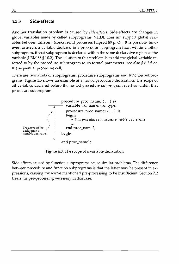
There are two kinds of subprograms: procedure subprograms and function subprograms. Figure 4.3 shows an example of a nested procedure declaration. The scope ofall variables declared before the nested procedure subprogram reaches within thatprocedure subprogram.
The scope of thedeclaration ofvariabIe var_name.
procedure proc_name1 ( ... ) isvariabIe var_name: vactype;
procedure proc_name2 ( ... ) isbegin
-- This procedure can access variabIe vacname
end proc_name2;
begin
end proc_name1;
Figure 4.3: The scope of a variabie declaration
Side-effects caused by function subprograms cause similar problems. The differencebetween procedure and function subprograms is that the latter may be present in expressions, causing the above mentioned pre-processing to be insufficient. Section 7.2treats the pre-processing necessary in this case.

TRANSLATION DECI5ION5 33
4.3.4 Statements without data transfer
Statements without any data transfer can not be translated into a data flow graph.There are two ways to create (sequential) statements without data transfer in VHDL.
CD Create a VHDL procedure subprogram without a parameter list. When this procedure is called, no data transfer takes place, and the resulting VHDL is nottranslatabIe into a DFG (see also § 6.2.5 on the procedure call).
@ The VHDL null statement has no data transfer. It is usually safe to ignore thenull statement completely. Sometimes, however, more statements must be ignored, when a statement contains nun statement(s) only.
Figure 4.4 illustrates this. The only statement in the while loop is a nun statement. Thus the while loop is actually a nun statement. Therefore the only statements within the if statement are nun statements, and the complete if statementhas to be ignored (see also § 6.2.10 on the nun statement).
if conditionthen
nun;else
while TRUE loopnun;
end loop;end if;
Figure 4.4: Alegal VHDL example without any data transfer
It is unlikely that constructs in the style of figure 4.4 occur within VHDL designs forsilicon compilation. Nevertheless the VHDL language allows them.
4.4 Conclusions
To conclude this chapter, the list of questions from the beginning of this chapter is repeated here, together with their answers.
CD Should the translator perform optimisations?
No. Most optimisations are performed at a later stage, and the translation shouldbe as literal as possible.

34 CHAPTER4
@ Should the translator rewrite the source code if its structure is bad?
No. See the answer to CD.
@ Can the target language induce obligatory pre-processing of the source code, andif so, should the translator perform this pre-processing?
Yes. Many of VHDL's sequential statements can not be translated unless samepre-processing is performed.
@ Is it possible to translate all statements?
No. Statements without data transfer and statements depending on the eventdriven model of VHDL can not be translated.

35
Chapter 5The Trans/ation of
Concurrent Statements
This chapter addresses the translation of VHDL concurrent statements into ASCrS dataflow graphs. Most of these statements can not be translated into DFGs because of themodel problem: the difference between the underlying model of VHDL and themodel of the ASCrS data flow graph (see chapter 2).
Section 5.1 presents an overview of VHDL's concurrent statements. Section 5.2 presents the actual translations of the statements. Section 5.3 contains the conclusions tothis chapter.
5.1 Overview
Concurrent statements in VHDL are used to define interconnected blocks and processes that jointly describe the overall behaviour or structure of a design. Concurrentstatements execute asynchronously with respect to each other [LRM 88 § 9], hencetheir name. The following sequential statements are defined:
Block statementProcess statementConcurrent procedure callConcurrent assertion statement
Concurrent signal assignment statementComponent instantiation statementGenerate statement
Within VHDL, concurrent statements are allowed within the following languageconstructs:
Architecture bodyBlock statement
Entity declarationt
Generate statement
There is only one VHDL concurrent statement, the process statement, which can contain sequential statements.
t Onlya select number of concurrent statements are allowed in the statement part of an entity declaration [LRM 88 § 1.1.3].

36 CHAPTERS
The grammar rules used to illustrate the syntax of VHDL statements in thisthesis are the same as those used in [LRM 88]. Briefly:
I or [ ] zero or one timex terminal character {} one or more times
5.2 Translation techniques
This section discusses the translation techniques for the concurrent statements ofVHDL. Chapter 2 defines the model problem, which explains why it is impossible totranslate VHDL signals and other constructs based on the event-driven model ofVHDL into the ASCIS data flow graph format. Because it might be possible that asolution to this problem will be available in the future, the following assumption ismade in the remainder of this chapter:
5.2.1
To be able to demonstrate the translation of VHDL's concurrent statements,the assumption is made that signais, signal assignments and event sensitivity can be translated into ASCIS data flow graphs.
The block statement
block_statement ::=block_label :
block [ (guard_expression) ]block_headerblock_declarative_part
beginblock_statemenCpart
end block [ block_label ] ;
block_header ::=[ generic_clause[ generîc_map_aspect; ] ][ porCclause[porCmap_aspect;] ]
block_declarative_part ::={block_declarative_item}
block_statemenCpart ::={concurrenCstatement }
A bloek statement defines an intemal block representing a portlon of a design.Blocks may be hierarchically nested to support design decomposition. If a guardexpression appears after the reserved word bloek. then a signal with the simplename GUARD of predefined type BDDLEAN is implicitly declared at the beginning of the declarative part of the bloek. and the guard expression defines thevalue of that signal at any given time [LRM 88 § 9.11.

THE TRANSLATION OF CONCURRENT STATEMENTS 37
The VHDL block statement provides a means to set off a part of a design by labellingit and enclosing it in syntactic brackets (block and end bloek). In the simplest case,these brackets have no effect whatsoever on the meaning or interpretation of themodel in which they appear. However, the block statement mayalso have a declarative part, which may define ports and generics of the block by providing a port interface and/or a generic interface list. [Lipsett 89 p. 158].
Next to these declarations a block statement mayalso have a guard expression. Thisexpression declares, and gives a value to, an implicitly declared signal with the nameGUARD which may be used (but not driven) in the entire declarative region of theblock statement. This signal is used to control guarded signal assignment statements(see § 5.2.5).
In other words: the block statement groups one or more concurrent statements, andmay place these in a context providing an interface to this group.
At the moment there is no way to implement VHDL signals and common signaIs inthe DFG (see chapter 2). The details of the block statement's translation however depend on the translation of signais, because the concurrent blocks in the block statement can communicate using (global) signaIs; the concurrent statements grouped inthe block statement can not share global variables (see table 5.1), but global signalsare allowed. The GUARD signal is such agiobal signal.
Table 5.1: Declarations available in the block statement
Basic declarationstype declaration
subtype declarationconstant declaration
file declarationalias declaration
subprogram declarationuse clause
Other declarationssignal declarationsubprogram body
attribute declarationattribute specification
disconnection specificationcomponent declaration
configuration specificationvariabie declaration
............................... ··.···.··..·.···...·....·.·...···.·.·................1îl!ml~atIBlln~·.· ....···
i<Î11ÎII'.•..
••••
i............
i.••••••••••••• allowedM{
not allowedLL

38 CHAPTERS
Figure 5.1 shows the general idea of the DFG translation of the block statement; theconcurrent statements within the block statement are translated into parallel dataflow graphs.
block_label:block
begin _Iconc_statement1; Cconc_statement2;
conc_statementN;end block block_label;
5.2.2
Figure 5.1: General translation of the block statement
The process statement
process_statement ::=[ process_label ]
process [ ( sensitivity_list) ]process_declarative_part
beginprocess_statement_part
end process [ process_label ] ;
process_declarative_part ::={process_declarative_item }
process_statemenCpart ::={sequentiaCstatement }
A process statement defines an independent sequential process representing thebehaviour of some portion of the design. If a sensitivity list appears following thereserved word process, then the process statement is assumed to contain animplicit walt statement as the last statement of the process statement part ofthe form "walt on sensitivity_list".
The execution of a process statement consists of the repetitive execution of ltssequence of statements [LRM 88 § 9.2].
The process statement contains a behavioural description of sequentiaI statements,and defines a declaration context for these statements. A process executes repetitively; after executing the last statement of a process, execution will immediately continue at the first statement of the sequence of statements.
The execution of the process statement is controllabie by the wait statement(see § 6.2.9). If the process has a sensitivity list, this list implicitly declares a waitstatement as the last statement of the process statement. Figure 5.2 illustrates this.

THE TRANSLATION OF CONCURRENT STATEMENTS 39
process_Iabel:process (sensitivity_list)
declarations;begin
statements;end process process_Iabel;
process_Iabel:process
declarations;begin
statements;wait on sensitivity_list;
end process process_Iabel;
Figure 5.2: Pre-processing the process statement with a sensitivity list
The process statement provides a bridge between the concurrent and the sequentialdescription levels [Lipsett 89 p. 65]. The process statement inherits the declarationsmade in its context, and the declaration part of the process statement may declarevariables for use by the sequential statements in its body. Table 5.2 shows the otherdeclarations that are available in the declaration part of the process statement.
Table 5.2: Declarations available in the process statement
Basic declarationstype declaration
subtype declarationconstant declaration
file declarationalias declaration
subprogram declarationuse clause
Other declarations
11111111~1~~mll~
I••••lilIi
signal declarationsubprogram body
attribute declarationattribute specification
disconnection specificationcomponent declaration
configuration specificationvariabIe declaration
To translate a process statement into a DFG, it is necessary to translate the sequentiaIstatements in its body first. Chapter 6 treats the translation of VHDL's sequentialstatements. The translation of these sequential statements produces a data flowgraph.
According to the definition of the process statement, this DFG has to execute continuously. The solution to this problem seems obvious; if statements have to be executedcontinuously, place these statements in an endless while loop, as in figure 5.3.

40 CHAPTER5
statements;
infinite_loop:while TRUE loop
statements;end loop infinite_loop;
Figure 5.3: Putting statements in an eternalloop
This while loop can only be translated if there is data flow from outside the whileloop to the sequential statements inside the while loop's body. If this is not the case,the while loop defines a statement without data transfer (see § 4.3.4), and the whileloop can not be translated using the translation technique described in section 6.2.3.
Not taking signais, for which there is currently no DFG translation possible, into account as contributing to data flow, there are two possibilities. Both possibilities require a different approach:
CD The declarative part of the process statement declares variables, which are usedby the sequential statements in the statement part of the process.
@ No variables are used by the sequentia1statements in the statement part of theprocess, which happens for instance when the statements only use signais.
Possibility CD does not introduce any problems. Fortunately, variables in VHDL arealways initialised [LRM 88 § 4.3.1.3]. This initialisation is done prior to the executionof the process statement, and therefore outside of the implicit while TRUE loop. Thismeans that there is data flow into the loop, and the implicit while loop can be translated as described in section 6.2.3.
,,,II
, I
'oQ. :
0-~IIIIIIII_______ .J
statements
Figure 5.4: Repeated execution of a DFG

THE TRANSLATION OF CONCURRENT STATEMENTS 41
Possibility @ causes more problems. In the conventional DFG model described in[Eijndhoven 91] it is possible to make a DFG repeat only by acting as if there weredata flow between the in and the out nodes. Figure 5.4 shows an example of this. Because this method is not really clean, a value node is recently proposed for incorporation in the ASCIS data flow graph standard.
The value node has one input and one output. It consumes tokens arriving at its input, and outputs them again one cycle-step later. The output edge of the value nodeinitially contains a token. Using this node the way figure 5.5 shows, it is possible toexecute a DFG continuously.
statements
Thisedgeof the valuenode initiallyholds a token.
Figure 5.5: Repeated execution of a DFG, part 11
The concurrent process statement and the sequential wait statement are closely intertwined. If a process uses signals and is sensitive to them by means of a wait statement (either explicitly, or implicitly using a sensitivity list) then its continuous execution can be interrupted. Figure 5.6 shows the life cycle of a single process statement(see § 2.3.1).
At the moment of writing, there still is no reasonable solution to this problem. Chapter 2 lists a number of possible approaches, none of which are real solutions. Theproblem is not that of making a process run continuously, the main problem for thetranslation of the process statement is the execution model of VHDL.

42
execution of theprocess ' sequentialy statements ~
resuming of the waitprocess statement
wait C~n~itiOn(S) () SUsp~:ionofthe
are me~\ pro7~
CHAPTER5
C)calculation ofnew currentsignal values CID
increment of thecurrent simulationtime
5.2.3
wait condition(s)are not met
Figure 5.6: The life cycle of a single process
The concurrent procedure call
concurrent_procedure_call ::=[ label: ] procedure_call_statement
A concurrent procedure caU represents a process statement containing the corresponding sequential procedure caU, foUowed by a walt statement.
If there exists a primary that denotes a signal in the actual part of any association element in the concurrent procedure caU, and that signal is associated witha formal parameter of mode In or lnout. then the equivalent process statementincludes a final walt statement with a sensitivity clause that contains the longeststatic prefix of each signal name appearing as a primary in an actual part andassociated with such a formal parameter; otherwise. the equivalent processstatement contains a final walt statement that has no explicit sensitivity clause.condition clause, or time-out clause [LRM 88 § 9.3].
This brilliant quote from the VHDL language reference manual states that it ispossible to rewrite the concurrent procedure caU into a process statement. Theintroduced wait statement allows the procedure to be called without having it loopcontinuously; the concurrent procedure call is sensitive to its incoming signais.Figure 5.7 illustrates this:

THE TRANSLATION Of CONCURRENT STATEMENTS 43
conc_proc_call:
:>process
11
_----____ beginproc_name (parameter_list); proc_name (parameteclist);
wait on sensitivity signals ofparameter_list;end process conc_proc_call;
Figure 5.7: Pre-processing the concurrent procedure call
After this pre-processing, the remaining statements are a process statement(see § 5.2.2), a sequential procedure call (see § 6.2.5) and a wait statement (see § 6.2.9).
5.2.4 The concurrent assert statement
concurrent_assertion_statement ::=[ label: ] assertion_statement
A concurrent assert statement represents a passive process statement containing the specified assertion statement [LRM 88 § 9.4).
The concurrent assert statement is equivalent to a single process statement without adeclarative part, and with no sensitivity list. This process statement contains two sequential statements: the assert statement, and a wait statement. This wait statementis sensitive to the signals used in the assert condition. If no signaIs are used, the waitstatement has no explicit sensitivity clause, condition clause, or time-out clause. Figure 5.8 illustrates this:
asserelabel:assert condition
report expressionseverity expression;
assert_label:process
assert conditionreport expressionseverity expression;
wait on sensitivity signals of the condition ;end process assert_label;
Figure 5.8: Pre-processing the concurrent assert statement
The remaining statements are a process statement (see § 5.2.2), a sequential assertstatement (see § 6.2.8) and a wait statement (see § 6.2.9).

44
5.2.5 The concurrent signal assignment statement
CHAPTER5
concurrenCsignaLassignmenCstatement ::=[ label: ] conditional_signal_assignment
I [label:] selected_signaLassignment
conditional_signal_assignment ::=target <= options conditional_waveforms;
conditionaLwaveforms ::={ waveform when condition else }
waveform
selected_signaLassignment ::=with expression select
target <= options selected_waveforms ;
selected_waveforms ::={ waveform when choices,}
waveform when choices
options ::= [ guarded ] [ transport]
There are two forms of the concurrent signal assignment statement. Each formmay include one or both of the two options guarded and transport. The optionguarded specifies that the signal assignment statement is executed when a signal GUARD changes from FALSE to TRUE. or when that signal has been TRUEand an event occurs on one of its inputs. The option transport specifies that thesignal assignment has transport delay [LRM 88 § 9.5].
The signal GUARD may be one of the implicitly declared GUARD signals associated with block statements that have guard expressions. or it may be an explicitly declared signaloftype BOOLEAN [LRM 88 § 9.5].
Both types of concurrent signal assignment are equivalent to a single process statement. If the original concurrent signal assignment statement has a label, the processstatement receives the same label. The body of the process statement contains signalassignment statements, whose form depends on the form of the concurrent signa1assignment statement. The following list shows how to construct the body of theprocess statement.
Q) If the concurrent signal assignment statement has the transport option, all signalassignment statements in the process' body must also bear this option.
@ If the concurrent signal assignment statement has the guard option (is a guardedassignment), the signaI assignment statement in the body of the process statementmust be conditional on this GUARD.

THE TRANSLATION OF CONCURRENT STATEMENTS 45
@ If the target of the concurrent signal assignment statement as weIl as the concurrent signaI assignment itself are guarded assignments, then the signal assignment statement in the body of the process statement must be conditional on thisGUARD, containing disconnection statements in its else part.
® If the concurrent signal assignment statement is guarded, or if any of the expressions refers to a signal, then the process statement's last statement is a waitstatement sensitive to those signais. Otherwise its last statement is a wait statement that has no explicit sensitivity clause, condition clause or time-out clause.
In a conditional concurrent signal assignment statement, the signal assignment in theequivalent process statement is included in an if statement. Figure 5.9 shows an example of the pre-processing of a conditional concurrent signal assignment statementwithout guarded signais:
assignment_Iabel:target <= options
waveform1 when condition1 elsewaveform2 when condition2 else
waveformN;
assignmenClabel:process
if condition1 thentarget <= waveform1;
elsif condition2 thentarget <= waveform2;
elsetarget <= waveformN;
end if;wait on sensitivety signals of the
waveform expressions ;end process assignmenClabel;
Figure 5.9: Pre-processing the conditional concurrent signal assignment statement
The selected concurrent signal assignment statement is much alike the conditionalconcurrent signal assignment statement except for the fact that the former results in aprocess statement containing a case statement. Figure 5.10 shows the pre-processingof a selected concurrent signal assignment statement without guarded signais.

46 CHAPTER5
when choiceN =>target <= waveformN;
end case;wait on sensitivity signals of the
waveforms and theexpresswn;
end process assignment_Iabel;
assignment_Iabel:process
case expression iswhen choice1 =>
target <= waveform1;when choice2 =>
target <= waveform2;I)waveformN when choiceN;
assignment_Iabel:with expression select
target <= optionswaveform1 when choice1,waveform2 when choice2,
Figure 5.10: Pre-processing the selected concurrent signal assignment statement
If the options of the original signal assignment of figure 5.9 and figure 5.10 includethe reserved word transport, then all signal assignments in the pre-processed versionmust also include the word transport.
The remaining statements are a process statement (see § 5.2.2), sequential signal assignment statements (see § 6.2.6), an if statement (see § 6.2.1), a case statement(see § 6.2.2) and a wait statement (see § 6.2.9).
5.2.6 The component instantiation statement
component_instantiation_statement ::=instantiation_label :
component_name[generic_map_aspect][port_map_aspect] ;
A component instantiation statement defines a sub-component of the design entity in which it appears and associates signals with the ports of that sub-component. This sub-component is one instance of a class of components defined by acorresponding component declaration [LRM 88 § 9.6].
Using a component instantiation, it is possible to make a design more structura1. Aconfiguration specification [LRM 88 § 5.2] binds component instantiations to existingdesign entities.
A component instantiation is comparable to a procedure call in an algorithmic language, but VHDL treats it more like a macro definition:

THE TRANSLATION OF CONCURRENT STATEMENTS
A component instantiation statement is equivalent to a pair of nested bloekstatements that couple the .bloek hierarchy in the containing design unit to aunique copy of the bloek hierarchy contained in another design unit (i.e., thesub-component). The outer bloek represents the component declaration; the inner bloek represents the design entity to which the component is bound[LRM 88 § 9.6.1].
47
In other words, pre-processing a component instantiation yields a block statementconsisting of the port declaration of the component declaration, the port map of theconfiguration specification binding the component declaration to a design entity, anda block statement representing that design entity.
component And2 ----port (in1, in2: in Bit;
0: out Bit);
for Lib: And2 useentity _And2CAnd2_Behaviour)port map (_in1 => in1,
_in2 => in2,0=> 0)'- ,
entity _And2 isport Cin1, _in2: in Bit;
_0: out Bit);constant Delay: Time := 0.1 ms;
begin-- assertion statements ij-- necessary
end_And2;
architecture _And2_Behaviour of _And2 isbegin
_0 <= _in1 and _in2 after Delay;end _And2_Behaviour;
Figure 5.11: Binding a component declaration to a design entity
An instantiation of the And2 component of figure 5.11 will result in the block statement of figure 5.12. The innermost block statement of the result contains the concurrent statements from the statement part of the design entity's entity declaration andits architecture body.

48
Ub:block
port (in1, in2: in Bit;0: out Bit);
port map (in1 => A,in2 => B,0=> C);
CHAPTER5
Ub: And2port map (A => in1, A
B=>in2, yC => 0);
begin_And2:
blockport Cin1, _in2: in Bit;
_0: out Bit);port map Lin1 => in1,
_in2 => in2,_0 => 0);
constant Delay: Time = 0.1 ms;begin
-- entity statements:-- none in this example-- architecture statements:_0 <= _in1 and _in2 after Delay;
end block _And2;end block Ub;
Figure 5.12: Pre-processing a component instantiation
The remaining statements are a block statement (see § 5.2.1) and the statements of thedesign entity the component is associated with. The port maps are connections ofsignals with other signals and pose no translation difficultiest .
5.2.7 The generate statement
generate_statement ::=generate_label :
generation_scheme generate{concurrent_statement}
end generate [ generate_label ] ;
generation_scheme ::=for generate_parameter_specification
I if condition
A generate statement provides a mechanism for interactive or conditional elaboration of a portion of a description [LRM 88 § 9.7).
Elaboration of a generate statement consists of the replacement of the generatestatement with zero or more copies of a block statement whose statement partconsists of the concurrent statements contained within the generate statement[LRM 88 § 12.4.2J.
t The actual treatment of ports and port maps depends on the way signals are handled. At the moment, this problem is still unsolved.

THE TRANSLATION OF CONCURRENT STATEMENTS 49
A generate statement provides a way to facilitate the description of regular structures, such as arrays of blocks, component instantiations or processes. This is possibIe in two different ways:
(î) The generate statement may capture part of a design in a for generation scheme.The generate parameter implicitly created by the for generation scheme is a constant object, that can be used, but not assigned too, in the body of the generatestatement.
@ The generate statement may make a portion of a design conditional by placing itin an if statement.
Interpretation of the generate statement takes place during the elaboration of a design. The generate statement is the VHDL equivalent of macros, which are availablein most programming languages. Figure 5.13 shows an example of the generatestatement, taken from [Lipsett 89 p. 125].
The VHDL language reference manual [LRM 88 § 12.4.2] defines the elaboration ofthe generate statement in the following way. A generate statement with a for generation scheme generates one block statement for each value in the range. A generatestatement with an if generation scheme, generates one block statement if the condition holds.
The 8-bit inverter isbuilt with thiscomponent: a I-bitinverter.
entity InverC8 is 15'
port ( Inputs: BiCvector (1 to 8);Outputs: out BiCvector (1 to 8));
end InverC8;
architecture InverC8 of InverC8 iscomponent Inverter <J .
port (11: Bit; 01: out Bit);end component;
beginInverC8_bits:
t>for I in 1 to 8 generateInv: Inverter port map (Inputs (1), Outputs (I));
end generate; \>. ...end InverC8; .
This defines the portinterface to this design:an eight-bit inverter.
This constructiongenerates 8 inverters andconnects them with the 8in- and outputs.
....
Figure 5.13: Usage of the generate statement
The translator can process (or actually interpret) the generate at compile-time. Theresulting VHDL code consists of block statements (see § 5.2.1), and the original concurrent statements from the statement part of the original generate statement.

50 CHAPTERS
5.3 Conclusions
The three most important concurrent statements are the block statement, the processstatement (in combination with the sequential wait statement) and the concurrentsignal assignment. These three statements pose true translation problems.
The other concurrent statements of VHDL are pre-processable into other statements.The following list shows the translatability of VHDL's concurrent statements:
• If the model problem is ignored, the block statement translates into a series ofparallel DFGs. If the model problem is not ignored, the block statement can notbe translated if there is signal communication between two or more concurrentstatements within the block statement.
• The concurrent procedure call, the concurrent assert statement, the concurrentsignal assignment statements, translate into a process statement, a wait statement and one or more sequentiaI statements.
• The component instantiation statement expands into block statements, containing the statements of the design entity the component is associated with.
• The generate statement is expandable at compile-time.
• The process statement can not be translated yet because there is no solution tothe model problem.
Table 5.3 and table 5.4 give an overview of the translatability of VHDL's concurrentstatements per statement, and in relation to the solution of other translatabilityproblems.
Table 5.3: The translatability of VHDL concurrent statements
------------------------------------------------------------------ ---
ConcurrentStatement
Block statementProcess statementConcurrent procedure callConditional signal assignmentSelected signal assignmentComponent instantiation statementGenerate statement
Translatabieinto a DFG
yes12
yes12
yes 2
yes12
yes12
yes12
yes 2
Preprocessingis necessary
nonoyesyesyesyesyes3
----------
1 This statement is translatabie if and only if the model problem can be solved.2 This statement's translatability depends on the translatability of other parts of VHDL (see table 5.4).3 This statement is translatabie at compile-time.

THE TRANSLATION Of CONCURRENT STATEMENTS
Table 5.4: Translatability related to other translation issues
51
signal 'execution, process wait' othermodel model ' stmt. stmt. conc.problem problem ' stmts. •
ConcurrentStatement
The statement's translation depends on I_~~~ s~~~tio~_to(!~~ tran~_!~tion_()i: -,----J--
other I
seq. I
stmts.
Block statement- - - - . _. . ~ .Process statement
'" çOl1ctlrrentproceciurecall,, , ,ÇOl1ditiol1al signal assignIl1ent, ," ,Selected signal,assigrnnent, """
Component instantiation statementGenerate statement
,~ 'j,\/.-
"\/.v.--'\/.' "\/"\/ ----"
· v·~::':-~"'\l' ,v. \/. \I.:,V:,: ...V.' '\/.' .,\1:'
\I

53
Chapter 6The Translation of
Sequential StatementsChapter 5 addresses the concurrent statements of VHDL. This chapter discusses thetranslation of the sequential statements of VHDL into ASCIS data flow graphs. It is possible to translate most of these statements into DFGs. Some statements need pre-processing before they are translatabIe because they have an irregular data flow or useconstructs not directly available in a DFG. Furthermore it is impossible to translatesome sequentia1statements.
Section 6.1 presents an overview of VHDL's sequentia1 statements. Section 6.2 presents the actual translations of the statements. Section 6.3 contains the conclusions tothis chapter.
6.1 Overview
Sequential statements in VHDL are used to define algorithms for the execution of asubprogram or a process; they execute in the order in which they appear in theVHDL source [LRM 88 § 8], hence their name. Using sequential statements, VHDL islike a programming language [Ashenden 90 p. 2-1]. The following sequential statements are defined:
Null statementAssertion statementIf statementCase statementLoop statementNext statementExit statement
Return statementProcedure call statementSignal assignment statementVariabIe assignment statementWait statement
These statements include statements for program flow-control (if, case,loop/next/exit and procedure-call/return statements), execution control (assert andwait statements) and expression evaluation (signal and variabIe assignment statements, and expressions in other sequential statements).

54 CHAPTER 6
Mainly because VHDL is not originally meant to be a formal specification language,the execution-flow of some of its statements is very unrestrained. Loops and subprograms for instance can be exit-ed at any time.
Within VHDL, sequential statements are allowed within the following languageconstructs:
Process statementSubprogram body (function and procedure subprograms)
A subprogram body is equivalent to a subroutine (procedure or function), and aprocess statement is one of the main building blocks of VHDL design: it provides abridge between the concurrent and the sequential description levels [Lipsett 89 p. 65].
Furthermore, sequential statements can occur as a part of the following sequentialstatements:
If statementCase statementLoop statement
The grammar rules used to illustrate the syntax of VHDL statements in thisthesis are the same as those used in [LRM 88]. Briefly:
xorterminal character
[ ] zero or one time{} one or more times
6.2 Translation techniques
This section discusses the translation techniques for the sequentia1 statements ofVHDL. Chapter 2 defines the model problem, which explains why it is impossible totranslate VHDL signals and other constructs based in the event-driven model ofVHDL into the ASCIS data flow graph format. Because it might be possible that asolution to this problem will be available in the future, the following assumption ismade in the remainder of this chapter:
To be able to demonstrate the translation of VHDL's sequential statements,the assumption is made that signaIs, signal assignments and event sensitivity can be translated into ASCIS data flow graphs.
The only sequential statements on which this has any effects are the wait statement,and the signal assignment statement.

THE TRANSLATION OF SEQUENTIAL STATEMENTS 55
6.2.1 The if statement
iCstatement ::=if condition
thensequence_oCstatements
{ elsif conditionthen
sequence_oCstatements }I else
sequence_oCstatements ]end if;
An lf statement selects for execution one or more of the enclosed sequences ofstatements depending on the value of one or more corresponding conditions. Anexpression specifying a condition must he of the type BOOLEAN [LRM 88 § 8.6).
The VHDL version of the if statement is basically equal to the ordinary if-then-elseconstruction. The only difference is the availability of an elsif commando
Within the ASCIS data flow graph, branch and merge nodes are available for if-thenelse constructs IEijndhoven 91 p. 32]. The general form of the if-then-else DFG isdrawn in figure 6.1 IVeen 85 p. 93].
A branch node is needed for every value that is used within the then or else blocks,and has a previous definition outside of these blocks (Vl ... Vn). A branch and mergenode pair is needed for every value that is changed within the then or else blocks(Wl"'Wm ). A branch and merge node pair is needed for every different 1/0 chainpresent within the then or else blocks, because 1/0 operations (put and get nodes)must always be chained [Eijndhoven 91 p. 10].
The branch and merge nodes are controlled by the (Boolean) result of the conditionalexpression. The edge labelled 1 of the branch and merge nodes is chosen when thecondition evaluates to true, the edge labelled 0 is chosen when the condition evaluates to false.

56
if conditionthen
statementsI;else
statements2;end if;
• • •
Figure 6.1: General translation of the if statement
CHAPTER6
controledge
The general form shown in figure 6.1 can be used for the VHDL if statement withoutany changes. The elsif is basically the same as else iff which results in another ifthen-else construction within the else statement of its parent. Every occurrence of anelsif results in one deeper nesting of an if-then-else statement. An example with twoelsifs is shown in figure 6.2.
if condition1then
statements1;elsif condition2
thenstatements2
elsif condition3then
statements3;else
statements4;end if;
if condition1:-- then: statementsI;i elseI
i if condition2. ..... .~.... :-- thenA i ....(\ i statements2yi i else
L '. i if condition3.: ... ~...: : "'(\ theni i statements3;i i elseI I
i i statements4;! i end if'I .._- ,
:_- end if;end if;
Figure 6.2: Pre-processing the elsif statement
This way of handling the elsif statement can result in more deeply nested DFGs thannecessary. The run-time behaviour of the elsif in VHDL however is the same:

THE TRANSLATION OF SEQUENTIAL STATEMENTS 57
For the execution of an if statement. the condition specified after if. and anyconditions specified after elsif. are evaluated in succession (treating a final elseas elsif TRUE then), until one evaluates to TRUE or all conditions are evaluatedand yield FALSE [LRM 88 § 8.6].
In my view, an if statement with many elsifs is a case of bad programming behaviour for which the translator should produce a warning. In most instances it ismuch more useful and efficient to use a case statement instead (see also section 6.2.2).
Figure 6.3 shows a small example of the DFG translation of a simple if-then-elseconstruction.
b
controledge
IIIIIIII
}---IIIIIIII
source··- ~dge
x
oME
:r
ifx=3then
x:= 5;y:= b;
elsey:= 7;
end if;
Figure 6.3: An if-then-else example
6.2.2 The case statement
case_statement ::=case expression is
case_statement_alternative{ case_statemenCalternative}
end case;
case_statement_alternative ::=when choices =>
sequence_oCstatements
A case statement selects for execution one of a number of alternative sequencesof statements; the chosen alternative is defined by the value of an expression.
The expression must be of a discrete type. or of a one-dimensional characterarray type (whose values are representable as string or bit-string literals).
The execution of a case statement chooses one and only one alternative. sincethe choices are exhaustive+ and mutuallyexclusive+. [LRM 88 § 8.7J.
+ Every possible value must be covered.:j: Every value is covered only once.

58 CHAPTER 6
The expression and the choices of the case statement have to be loeally statiet. Thismeans that their values can be calculated at the time of compilation. The branch andmerge nodes of the ASCIS data flow graph may have more branches than the twobranches labelled 0 and 1 as present in the if statement.
Attached to each branch node is a selection list, which is an ordered list associatingmutually exclusive values with one of the outgoing ports of the branch node[Eijndhoven 91 § 2.5]. By using the selection list, the case statement can be translatedinto a DFG consisting of branch and merge nodes with an edge for every case statement alternative.
Figure 6.4 shows the general translation of the case statement using branch andmerge nodes and selection lists. A branch node is needed for every value that is usedwithin the alternative case blocks, and has a previous definition outside of theseblocks (Vl ... Vn ). A branch and merge node pair is needed for every value that ischanged within the alternative case blocks (Wl ...Wm).
A branch and merge node pair is needed for every different IlO chain present withinthe alternative case blocks, because IlO operations (put and get nodes) must alwaysbe chained [Eijndhoven 91 p. 10].
t A locally statie expression is an expression which can be evaluated during the analysis of the designunit in whieh it appears [LRM 88 § 7.4].

THE TRANSLATION OF SEQUENTIAL STATEMENTS 59
.--- "-
BR
controledge
• • •
\
choiceN',I: choicel
I" choicel
when chokeN => 'I ,
statementsN;: ME -J----------end case' "
:.-;hOireÎ ,-/ t:,i \!
choiceNi dataI edge
\",,<hOi,,~/~/__W,••• Wm V, .•.
case expression is BR -t---------when chokel =>
statementsl;when choke2 =>
statements2;
ME"
"
Figure 6.4: General translation of the case statement
Due to the way the selection list of branch and merge nodes is currently implemented, it is very inefficient to use selection lists when the possible chokes of thecase statement cover a large range. Thus, when the type of the case expression coversa range of N values, Uog2 (N~ =: M bits are necessary to be able to represent its possibie values, and the selection list must contain 2M entries; independent of the numberof chokes in the case statement.
In this case some pre-processing is necessary to be able to translate the case statementefficiently. The case statement can be rewritten into an if statement. Every choke istranslated into an elsif part of the if statement. The final choke is pre-processed intoan else statement instead of an elsif statement because the chokes are exhaustive. Toprevent the original case's expression to be calculated more than once, a variabie isintroduced to store the value of the expression.
The resulting expression has the same behaviour as the case statement: at least one altemative is chosen because the chokes are exhaustive, and exactly one of the alternatives is chosen because all choices are mutually exclusive. This is illustrated infigure 6.5.

60
case expression iswhen choicel =>
statementsI;when choice2 =>
statements2;
when choiceN =>statementsN;
end case;
CHAPTER 6
case_varl := expression;
if case_varl = choicel thenstatementsI;
elsif case_varl = choice2 thenstatements2;
elsestatementsN;
end if;
Figure 6.5: Pre-processing the case statement into an if statement
This pre-processing actually introduces a deeply nested if-then-elsif statement,which I claim to be a case of bad programming (see § 6.2.1). Whether it is more efficient to implement the case statement using branch and merge nodes and aselectionlist, or to pre-process the case statement into an if-then-elsif nesting, depends on thetype of the case expression, and the number of choices in the case statement.
Next to expressions, there are two other possibilities to specify a choice. Choices mayspecify more than one alternative, and the keyword others can be used as a choice.
When it is inefficient to use branch and merge nodes and a selection list, it is possibleto rewrite this case statement into an if statement as weIl. The if expression of atranslated choice with more than one alternative consists of an or clause for every alternative. The others alternative translates into the final else part of the if statement.Only choices that fall through the others alternative in the original case statement fallthrough to the final else part, because all choices are exhaustive.
case expression iswhen choicel =>
statements1;when choice2 I choice3 => A
statements2; ywhen others =>
statementsN;end case;
case_varl := expression;
if case_varl =choicel thenstatementsI;
elsif case_varl = choice2 orcase_varl = choice3 then
statements2;
elsestatementsN;
end if;
Figure 6.6: Pre-processing the case statement into an if statement, part TI
Special care has to be taken when the '=' operator has been overloaded (see § 8.1.1).The VHDL language reference manual explicitly states the following:
Overloading the operator "=" has no effect on the semantics of case statementexecution [LRM 88 § 8.7].

THE TRANSLATION OF SEQUENTIAL STATEMENTS 61
Thus, if the case statement is, by pre-processing, translated into an if statement, the,=' comparison introduced can not be overloaded.
6.2.3 The loop, next and exit statements
loop_statement ::=[ loop_label : 1
[ iteration_scheme ] loopsequence_oCstatements
end loop [ loop_label] ;
iteration_scheme ::=while conditionfor loop_parameter_specification
parameter_specification ::=identifier in discrete_range
next_statement ::=next [ loop_label] [ when condition ] ;
exit_statement ::=exit [ loop_label] [ when condition ] ;
A loop statement includes a sequence of statements that is to be executed repeatedly. zero or more times [LRM 88 § 8.8].
For a loop statement with a for iteration scheme. the loop parameter specification is the declaration of the loop parameter with the given identifier. The loopparameter is an object whose type is the base type of the discrete range. Withinthe sequence of statements, the loop parameter is a constant [LRM 88 § 8.8].
A next statement is used to complete the execution of one of the iterations of anenclosing loop statement (called "loop" In what follows). The completion is condltional if the statement includes a condition [LRM 88 § 8.9].
An exit statement is used to complete the execution of an enclosing loop statement (called "loop" in what follows). The completion Is conditional if the statement lncludes a condition [LRM 88 § 8.10].
The VHDL loop statement has three major farms. Two with an iteration scheme (thewhile loop and the for loop) and one without an iteration scheme. The latter is an infinite loop, unless its body is escaped from using either a next, an exit, or -in case ofa function subprogram- a return statement. These escape-statements can also occurwithin the loops that do have an iteration scheme.
Section 4.3.2 explains why some pre-processing is necessary to be able to translate theloop statement containing escape-statements into a DFG. If a loop has to be exit-edregardless of its exit condition, a flow-control variabie is needed, which controls theexit condition of the loop, and controls conditional execution of statements followingthe escape-statement.
Section 6.2.3.1 treats loops without escape-statements, and 6.2.3.2 treats the pre-processing that is necessary to be able to translate loop statements with escapestatements.

62 CHAPTER 6
6.2.3.1 Loop statements without escape-statements
Within the DFG, entry and exit nodes are available for loops [Eijndhoven 91 p. 32].The most comman farm of loop is a loop of the while condition do body farm. The generaI loop structure drawn in [Eijndhoven 91 p. 9] differs slightly fram the one shownhere. In VHDL, contrary to languages like c where operators like + + are available, itis impossible to change the value of a variabie in an expressiont . Therefore there isalways a direct data edge between the entry and the exit nodes.
An entry and exit node pair is needed for every variabie that is used within the loop,and is declared outside of the loop (Vl ...Vn). An extra entry and exit node pair is alsoneeded for every different 1/0 chain present within the loop.
dataedge
• • • V n____--=--i-~
-----,IIIIIIIII
---- -------~
II,
.---- EX
o
contraledge
Figure 6.7: General translation of the loop statement
This general translation of the loop statement is based on the general while loop. TheVHDL while loop fits in this scheme, but the for loop and the conditionless loop cannot be fitted in directly.
According to [Veen 85 p. 99], a for loop is a while loop with an empty test part and aspecial contral node. The ASCIS data flow graph described in [Eijndhoven 91] doesnot support any special nodes for the translation of for statements. The VHDL forloop can easily be rewritten as a while loop.
t Within certain limits. To be able to handle function subprograms that access global variables it isnecessary to break this rule. In this case there is a DFG expression between the entry and the exitnodes (see § 7.2).

THE TRANS LATION Of SEQUENTIAL STATEMENTS
loop1:for loop_variabie in range_start to range_end loop
statementsI;end loop loop1;
{}loop_variabie := range_start;loop1:
while is_inJange (loop_variable, range_start, range_end) loopstatementsI;incrementaCoperator (loop_variabie);
end loop loop1;
Figure 6.8: Pre-processing of the for loop
63
The exact definitions of is_inJange () and incrementaCoperator () depend on the datatype of the loop variabie (called loop-parameter in [LRM 88]). The incremental operator is not part of the loop's statements. A next statement will jump to this operator,and not to the end loop statement, as it would for other loops (see § 6.2.3.2).
The loop variabie in a VHDL for loop statement is local to the loop.
The simple conditionless loop can easily be made conditional. It can be convertedinto a while loop with a condition that is always TRUE.
loop1:loop
statementsI;end loop loop1;
loop1:
I) while TRUE loopstatementsI;
end loop loop1;
Figure 6.9: Pre-processing of the plain loop statement
Figure 6.10 shows a small example of the DFG translation of a simpIe for loop without any escape-statements.

64 CHAPTER 6
z
dataI edge
xo
contra1edge
ii___________ ..J
010
-s-ta-t-em-e-:-t-p-a-r-t---y- " I control part J
loop1:for x in 0 to 41 loop
y:= y + x;z:= z + 1;
end loop loop1;
Figure 6.10: A for loop example
6.2.3.2 Loop statements with escape-statements
The previous section shows how the three basic loop constructs of VHDL can betranslated into DFGs. Basically one loop construction remains: the while loop. Thismeans that in order to derive the pre-processing necessary to be able to translate escape-statements, only the while loop needs to be analysed. The following list showsthe actions that should take place when an escape-statement occurs.
(î) The statement(s) the escape-statement occurred in have to be exit-edimmediately.
@ All statements following the escape-statement, until and including the last statement of the loop's original statements, must not be executed. (Note that theincrementaCoperator () found in a pre-processed for loop is not part of the loop'soriginal statements.)
@ In case of an exit or a return statement, the loop itself must be exit-edimmediately.
To implement this, a flow-control variabie has to be introduced. When its value isTRUE, the loop is in a normal state. When its value is FALSE, an escape-statement hasoccurred.
To implement the next statement, the flow-control variabie has to be set at the beginning of every iteration of the loop. If a next statement contains a condition, it has to berewritten into an if statement. An example of this is shown in the following figure:

THE TRANSLATION OF SEQUENTIAL STATEMENTS 65
loop1:while condition1 loop
statements1;
next loop1when condition2;
statements2;end loop loop1;
loop1:while condition1 loop
not_nexcloop_1:= TRUE;statements1;
c) if condition2 thennoCnexCloop_1:= FALSE;
end if;
if not_nexCloop_1 thenstatements2;
end if;end loop loop1;
Figure 6.11: Pre-processing a loop with a next statement
To implement the exit and return statements, the flow-control variabie has to be setbejore the loop, and -to implement ®- the while condition has to be anded with thevariabie. If an exit statement contains a condition, it has to be rewritten into an ifstatement.
loop1:while condition1 loop
statements1;
exit loop1when condition2;
statements2;end loop loop1;
noCexit_loop_1:= TRUE;loop1:
while not_exit_loop_1 and condition1 loopstatements1;
>if condition2 thenC noCexicloop_1:= FALSE;end if;
if nocexiCloop_1 thenstatements2;
end if;end loop loop1;
Figure 6.12: Pre-processing a loop with an exit statement
Item CD in the list needs some more clarification. There are three VHDL sequentialstatements, the if statement, the case statement and the loop statement itself, whichmay contain other sequential statements (see § 6.1). This means that escape-statements can occur within them.
The if and the case statements exit automatically when the sequence of statements, ofwhich the escape-statement is a part, finishes. If the escape-statement is contained ineither an if or a case statement no special actions are necessary. If the escape-statement is contained in a loop, that loop has to be exit-ed as weIl.
The following list defines all actions to be taken to manage escape-statements inloops:

66 CHAPTER6
CD If a loop statement has an associated exit statement, introduce a flow-controlvariabie that is set to TRUE outside of the loop, and and the loop's conditionwith it.
@ If a loop statement has an associated next statement, introduce a flow-controlvariabie that is set to TRUE as the first statement of the loop.
@ If a loop statement has any escape-statements, replace them with a variabie assignment statement to set the flow-control variabie associated with the escapestatement to FALSE. If the escape-statement is conditional (if it contains a whenpart), this assignment too must be conditional.
@ If a loop statement has any escape-statements, make all statements between theescape-statement and the last statement of the loop it is associated with conditional to the associated flow-control variabie.
® If a loop statement having escape-statements contains other loop statements,these loop statements' conditions should be anded with the flow-control variabieassociated with the escape-statement if the escape-statement occurs within them.
As an example, figure 6.13 shows the result of this technique for a doubly nestedloop, where the inner loop contains a conditional exit out of the outer loop.
noCexit_loop1:= TRUE;loop1:
while nocexiCloop1 and condition1 loopstatementsI;
loop2:while noCexit_loop1 and condition2 loop
statements2;
if condition3 thennoCexiCloop1:= FALSE;
end if;
if nOCexiCloop1 thenstatements3;
end if;___ end loop loop2;
if noCexit_loop1 thenstatements4;
end if;end loop loop1;
jump
statements3;end loop loop2;
statements4;end loop loop1;
loop1:while condition1 loop
statements1;
loop2:while condition2 loop Q..
statements2; -.
exit loop1when condition3; -
Figure 6.13: Pre-processing escape-statements- an example
After pre-processing, the resulting VHDL text is translatabie into a DFG.

THE TRANSLATION OF SEQUENTIAL STATEMENTS 67
6.2.4 The return statement
return_statement ::=return [ expression ] ;
A return statement is used to complete the execution of the innermost enclosingfunction or procedure body. A return statement appearing in a procedure bodymust not have an expression. A return statement in a function body must havean expression. It is an error if execution of a function completes by means otherthan the execution of a return statement [LRM 88 § 8.11).
The return statement has almost the same behaviour as the exit statement describedin the previous section, but instead of jumping out of a loop, the return statementjumps out of a subprogram.
There are two kind of subprograms: procedure and function subprograms, and thedefinition and the translation of the return statement is different for both of these.Section 6.2.4.1 treats the return statement when it occurs in a procedure body, andsection 6.2.4.2 treats it when it occurs in a function body.
6.2.4.1 The. return statement in a procedure body
If the return statement occurs in a procedure body, it implies a jump to the end of theprocedure body, and the same techniques as with the exit statement can be applied(see § 6.2.3.2). This results in the following actions:
CD If a procedure body has an associated return statement, introduce a flow-controlvariabie that is set to TRUE as the first statement of the procedure body.
@ In a procedure body, replace all occurrences of return statements with a variabieassignment statement to set the flow-control variabie to FALSE.
@ If a return statement occurs within a loop statement, this implies an exit statement out of the outermost loop.
@ If a procedure body has an associated return statement, make all statements between the return statement and the last statement of the procedure body conditional to the associated flow-control variabie.
To implement this, a flow-control variabie has to be introduced. When its value isTRUE, the procedure body is in a normal state. When its value is FALSE, a returnstatement has occurred. More details are found in section 6.2.3.2, which explainstechniques to handle escape-statements in loops.
After pre-processing, the resulting VHDL text is translatabie into a DFG.
As an example, figure 6.14 shows the result of this technique for a procedure subprogram whose procedure body contains a return statement in a loop statement.

68 CHAPTER 6
loop
procedure proc_name ( ... ) isvariabIe not_return: BOOLEAN;
beginnot_return:= TRUE;statementsI;
loop1:. while not_return and condition1
statements2;
not_return:= FAL5E;
if not_return thenstatements3;
end if;end loop loop1;
if not_return thenstatements4;
end if;end proc_name;
jump
return;
statements3;end loop loop1;
statements4;end proc_name;
procedure proc_name ( ... ) isbegin
statements1;
loop1:while condition1 loop
statements2;
Figure 6.14: Pre-processing the return statement in a procedure bodyt
6.2.4.2 The return statement in a function body
If the return statement occurs in a function body, it implies a jump to the end of thefunction body. A return statement in a function body must have an expression, whichimplies that a value has to be passed along with the jump to the end of the functionbody. Furthermore, the only way a function subprogram is allowed to exit is bymeans of a return statement. This results in the following actions:
CD If a function body has an associated return statement, introduce a flow-controlvariabie that is set to TRUE as the first statement of the function body, and introduce a return-value variabie with the same type as the return value of the function subprogram.
@ In a function body, replace all occurrences of return statements with a variabieassignment statement to set the flow-control variabie to FAL5E, and a variabieassignment assigning the result of the expression following the return statementto the return-value variabie.
@ If a return statement occurs within a loop statement, this implies an exit statement out of the outermost loop.
® If a function body has an associated return statement, make all statements between the return statement and the last statement of the function body conditional to the associated flow-control variabie.
t Examining this example closely will reveal that statements3 is never executed. This is not true ingeneral: the return statement could reside in a conditional statement, in which case statements following the return statement are possibly executed.

THE TRANSLATION OF SEQUENTIAL STATEMENTS 69
@ If a function body has an associated return statement, add a return statementwith the retum-value variabie as its expression as the last statement of the function body.
® Check whether all possible paths out of the function subprogram end with areturn statement.
function funcname (... )return type_mark is
begin. statementsI;
loopl:while conditionl loop
statements2;
return expression;
statements3;end loop loopl;
statements4; jumpend func_name;
L)
function func_name (... )return type_mark isvariabIe retum_value: type_mark;variabIe noCreturn: BOüLEAN;
beginnoCreturn := TRUE;statementsI;
loopl:while noCreturn and conditionl loop
statements2;
retum_value := expression;not_return:= FAL5E;
if not_return thenstatements3;
end if;end loop loopl;
if noCreturn thenstatements4;
end if;
return return_value;
end func_name;
Figure 6.15: Pre-processing the return statement in a function body
Point ® needs more c1arification. This point is important for the following tworeasons:
• The VHDL definition of a function subprogram demands it.
• If this check is not performed the source code may not be correct (it may containa path out of the function body without any return statements) whilst the preprocessed form is correct (it ends with a return statement, therefore every pathout of the function bodyends with a return statement).
This check can be done by building a statement-tree while parsing the function body.All paths of the statement tree have to contain (end with) a return statement. Anotherpossibility is to perform the validity check of a function body on the fly while parsing, using the actions shown in table 6.1.

70 CHAPTER6
Table 6.1: Checking the validity of a function body
Statement
Assertion statementNull statementVariabie assignment statementSignal assignment statementWait statementProcedure call statement
Case statementIf statement
Loop statementExit statementNext statement
Return statement
Action, validity of current block
No actions necessary. None of thesestatements split the execution flow in anyway.
The current block validity is unchanged.
The current block is valid if all sub-blocksare valid and is otherwise unchanged.
No actions necessary, a loop might executeonly once, depending on its condition.
The current block validity is unchanged.
The current block is valid.
This validity check is much more stringent than the check performed by VHDL. Thereason is that VHDL performs these checks at simulation time, where paths not ending with a return statement may never be reached, and therefore do not produce anerror.
6.2.5 The procedure call statement
procedure_caIl_statement ::=procedure_name [ (actual_parametecpart) ] ;
actual_parametecpart ::= parameter_association_list
association_list ::=association_element {, association_element }
A procedure caB invokes the execution of a procedure body [LRM 88 § 8.5).
A VHDL subprogram is one of the two language constructs that can contain sequential statements. A subprogram can be either a procedure or a function subprogram. Afunction subprogram can only be called from within an expression. Section 7.2 explains more about VHDL's expressions.
In general, if a procedure subprogram contains translatabie sequentiaI statements, theprocedure subprogram can be translated into a DFG. All parameters of type in or outbecome in- or out-nodes respectively in the resulting DFG. Parameters of type inoutboth have an in- and an out-node.

THE TRANSLATION OF SEQUENTIAL STATEMENTS 71
The resulting graph can be seen as a node (:: ), and can be instantiated as such inplaces where there is a call to the procedure subprogram. Figure 6.16 shows the general translation of a procedure subprogram.
Xl ••• Xn
G······ Gprocedure proc_name
(variabIe Xl, ... , Xn: in INTEGER;variabIe YI, ..., Ym: out INTEGER) is
begin c>statements;end proc_name;
.. out
YI • • • Ym
Figure 6.16: General translation of a procedure subprogram
There are, however, a couple of exceptions where this generaI translation can not beused. These exceptions are caused by the following properties of the VHDL procedure subprogram:
CD A procedure subprogram can refer to signalor variabie objects declared outsidethe declarative region associated with the procedure subprogram.
@ The parameter specification of the procedure subprogram is optional.
@ The parameter specification of the procedure subprogram may only contain parameters of type in or only parameters of type out.
According to item number CD of this list a VHDL procedure subprogram may refer toglobal variables. VHDL does not support global variables between different(concurrent) processes [Lipsett 89 p. 69], but it is possible to access one variabiewithin a single process from more than one subprogram declared within the declarative region associated with that subprogram [LRM 88 § 10.2].
In order to translate a procedure subprogram that refers to objects declared outside it,the procedure subprogram has to be pre-processed. A solution to this problem, assuggested in [Veen 85 p. 100], is to pass the global variabie as one of the parametersof the procedure subprogram. If the global variabie is assigned to in the procedurebody, this parameter has to be of the type inout. If it is only used, this parameter canbe of the type in. Figure 6.17 shows an example of this pre-processing for a proceduresubprogram defined in the declaration part of a process statement, accessing a variable defined before the subprogram specification.

begin
process_label:process
variabie var_name: var_type;
72
process_label:process
variabie var_name: var_type;
procedure proc_name ( ... ) isbegin
-- uses the 'global' variabIe~~ .called var_name. A
end proc_name; Y
CHAPTER 6
procedure proc_name( ... ;
variabie vacname: inout var_type) isbegin
-- uses the 'global' variabIe-- called var_name.
beginend process process_label;
end process process_label;
Figure 6.17: Pre-processing a procedure subprogram accessing global variables
Case @ and @ raise similar problems. Both introduce statements with irregular orwith no data flow (see § 4.3). Thus, if a procedure subprogram has a formal parameter list with parameters of type in or parameters of type out only, or lacks a formalparameter list completely, the procedure subprogram can not be translated.
Table 6.2 lists the declarations that are allowed in the declaration part of a subprogram. A subprogram can not declare any signals. It is allowed to specify a subprogram within a subprogram, and this child subprogram inherits the declarations madebefore its declaration in the parent subprogram.

THE TRANSLATION Of SEQUENTlAL STATEMENTS
Table 6.2: Declarations available in a subprogram
73
6.2.6
Basic declarationstype declaration
subtype declarationconstant declaration
file declarationalias declaration
subprogram declarationuse clause
Other declarationssignaI declarationsubprogram body
attribute declarationattribute specification
disconnection specificationcomponent declaration
configuration specificationvariabie declaration
The signal assignment statement
allowed ..not allowed •
signal_assignmenCstatement ::=target <= [ transport] waveform;
A signal assignment statement modifies the projected output waveforms contained in the drivers of one or more signals [LRM 88 § 8.31.
The signal assignment statement updates the projected output waveform of a signal.
The projected output waveform model of VHDL is not translatabie into a DFG(see chapter 2) and therefore it is not possible to translate the signal assignment statement into a DFG.
6.2.7 The variable assignment statement
variable_assignment_statement ::=target := expression ;
target ::=name I aggregate
aggregate ::=( elemenCassociation
{,elemenCassociation })
A variabIe assignment statement replaces the current value of a variabIe with anew value specified byan expression [LRM 88 § 8.41.

74 CHAPTER 6
The VHDL variabIe assignment has two forms. One where the target of the expression is a name that denotes a variabIe, and one where the target is an aggregate. Assigning a (new) value to a variabIe results in a new edge in a DFG. The VHDL variable assignment statement can therefore directly be translated into a DFG when thetarget of the expression is a variabIe.
When the target is an aggregate, the statement is actually a shorter description ofmultiple assignments. An example:
type Fraction isrecord
Numerator: INTEGER;Denominator: INTEGER;
end record;
variabIe Approx_Pi: Fraction;
Approx_Pi := (355, 113);
Here the variabIe Approx_Pi is assigned the aggregate (355, 113). This is functionallyequivalent to two assignment statements assigning 355 to Fraction.Numerator and113 to Fraction.Denominator.
When a variabIe assignment statement is executed, all the names in the aggregate areevaluated first. Then the expression is evaluated, and lastly the components of the expression are assigned to the named variables. Therefore an assignment to an aggregate is effectively a parallel assignment. This is illustrated by the following example,adapted from [Ashenden 90 p. 2-10]:
variabIe foo: Fraction;
-- Calculate reciprocal value of foo(Nominator => foo.Denominator, Denominator => foo.Nominator) := foo;
It is impossible to rewrite the previous aggregate assignment statement into two separate assignments without having to introduce a help-variable to temporarily storeone of the two sub-parts of foo. Fortunately it is not necessary to rewrite the aggregate assignment statements, because the problem does not occur in DFGs. This isshown in figure 6.18; when an assignment is made to a variabIe, its previous value isstill available. Only values exist in a data flow graph, there is no notion of variables.

THE TRANSLATION OF SEQUENTIAL STATEMENTS 75
x from befare x from afterthe addition the addition
Figure 6.18: Example of an assignment in a DFG
Figure 6.19 shows the general translation of the VHDL variabIe assignment statement. The expression is translated into a DFG (see section 7.2 on the translation of expressions) and new data edges are created for the target the result of the expression isassigned to. Multiple data edges are created if the target is an aggregate.
v := expression;
v ~ dataedge
Figure 6.19: General translation of a variabIe assignment statement
6.2.8 The assert statement
assertion_statement ::=assert condition
[ report expression ][ severity expression ] ;
An assertion statement checks that a specified condition is TRUE and reports anerror if ft is not.
U the report clause is present, it must include an expression of predefined typeSTRING that specifies a message to be reported. U the severity clause is present,it must specify an expression of predefined type SEVERITY_LEVEL that specifiesthe severity level of the assertion [LRM 88 § 8.2).
The ASCIS data flow graph does not support any assertion techniques. The assertstatement can not be translated directly into a DFG.
The VHDL assert statement is used for testing purposes. It provides a run-timemeans for debugging and error checking. If such a statement is to be used in a synthesis system, the target hardware should be able to report assertion techniques.

76 CHAPTER6
It is possible to rewrite the assert statement into statements that can be translated. ADFG has a special node called the put node which, together with the get node provides an interface to the outside world. A put node can be used to report the assertionmessages, and the assert statement can be rewritten to a simpIe if statement.
assert conditionreport expression1severity expression2;
if condition
L) thenput (assert.port, expressionl);put (assert.....port, expression2);
end if;
Figure 6.20: Pre-processing the assert statement
The put (assert.....port, expression) statement shown in figure 6.20 is not part of VHDL.VHDL does have read and write operations on files, but the put statement used hereis a simple representation of the put node found in the ASCIS data flow graph. Thetranslation of the assert statement results in an if-then DFG, with an extra branch andmerge node pair to chain the put nodes (see § 6.2.1). In VHDL it is impossible to alterthe value of a variabie in an expression, and therefore no merge nodes are needed forthe values used in expression1 and expression2+.
controledge
• • •
. ------- BR
•••dataedge
!,,IiI
. I. . I
~1 0 '_M~ J
_ Ij JL-BR k----- BR
chain 1VO 1edge .. ' .
i/o chain v 1
assert conditionreport expression1severity expression2;
i/o chain
'ij
Figure 6.21: General translation of the assert statement
t See the note on this subject in section 6.2.3.1.

THE TRANSLATION OF SEQUENTIAL STATEMENTS 77
It is questionable whether it is useful to translate the assert statement. It will probablyhardly ever be used for high-level synthesis, and it puts demands on the targethardware (the reserved output port for assertion messages).
Furthermore, the expression in the report clause in the assert statement should be ofthe VHDL predefined type STRING, of which there is currently no equivalent available within the ASCIS data flow graph [Eijndhoven 91 p. 14]. A solution may be toconsider a text string as a sequence of ASCII values, and to devise a construction toput those values individually. This, however, is rather inefficient and could result in alarge DFG.
The most logical conclusion is to exclude this statement until there is a way to handletext strings in the ASCIS data flow graph.
If the DFG has a data type to handle text strings, the generaI translation shown in figure 6.21 can be used.
ERRORIIIIII
icontroli edgeII, , I
'~--------------- J
data I Ni/0 chain edge prog ame a
~--------- BR --------------1 '00)chain 1V~ 1,-' __ : ~edge " :" ../ -'1:\ r---- <
~ IIIII
assert a < 10report progName &
": Error: a ~ la!"severity ERROR;
i/o chain
Figure 6.22: An assert example

78
6.2.9 The wait statement
CHAPTER 6
wait_statement ::=wait
[ sensitivity_clause ][ condition_clause ][ timeout_clause ] ;
condition_clause ::=until boolean_expression
sensitivity_clause ::=on sensitivity_list
sensitivity_list ::=signaCname {, signaCname }
timeout_clause :=for time_expression
The walt statement causes the suspension of a process statement or aprocedure.
The sensitivity clause defines the sensitivity set of the wait statement, i.e., the setof signals to which the walt statement is sensitive.
The condition clause specifies a condition that must be met for the process tocontinue execution. If no condition clause appears, the condition clauseuntil TRUE is assumed .
The time-out clause specifies the maximum amount of time the process will remain suspended at this walt statement. [LRM 88 § 8.1].
The translation of the wait statement depends, in combination with the translation ofthe process statement, on the model problem.
At the moment it is not possible to translate the wait statement. More on VHDL's execution model, its signal model and the process statement is available in chapter 2and section 5.2.2.
6.2.10 The null statement
nulCstatement ::= nul1 ;
A nu11 statement performs no action. The execution of the nuU statement has noeffect other than to pass on to the next statement [LRM 88 § 8.12).
The nul1 statement does nothing. The main reason of this statement's existence is thatit is sometimes necessary to be able to specify a null action. The VHDL case statement(see § 6.2.4) demands its choices to be exhaustive, and the nul1 statement is thereforenecessary when not all of its choices have an associated action.

THE TRANSLATION Of SEQUENTIAL STATEMENTS 79
1>'
case Selector iswhen "00" =>
statements1;when "01" =>
statements2; t>
when "10" I "11" =>nun; <}""'" '-, '.
end case;
The Selector's ranl!e is["00", "Ol", "11", "'10"].
Choice "10" and "11"have to be present inthe case.
But neither ofthem performany actions.
Figure 6.23: The necessity of the VHDL nun statement
The null statement does not have any associated data flow, and therefore it is notrepresentable in a DFG. Since the nun statement does not perform any actions, it cansafely be ignored.
It is possible to devise constructs where the nun statement gives rise to problems.Consider the following simple example:
if expressionthen
nun;else
nun;end if;
Figure 6.24: A problem with the nun statement
The body of the if statement in this example does not have any data flow, and can notbe translated into a DFG. The expression however might have side-effects (see § 7.2),and may not be ignored. In general, if a nun statement occurs in VHDL, it is possiblethat the statement it occurs in lacks data flow and must be ignored except for expressions with side-effects.

80 CHAPTER 6
6.3 Conclusions
Most sequential statements of VHDL are not event-driven. Only the signal assignment statement and the wait statement depend on the event-driven model and cannot be translated unless the model problem is solved (see chapter 2). Of the remaining sequential statements only the assert statement can not be translated; it uses theSTRING data type, which does not have a DFG equivalent. The other statements canbe translated although some pre-processing is necessary prior to translation. Anoverview is found in table 6.3.
The following list provides the most important conclusions to the contents of thischapter:
• VHDL's sequential statements provide programming techniques found in mostalgorithmic programming languages.
• It is possible to use VHDL's sequential statements to write structured algorithms,but unstructured programming is not forbidden.
• The assert statement can not be translated. This is not a big issue because theassert statement is not necessary for HLS.
• Only the wait statement and the signal assignment statement can not be translated because of the model problem discussed in chapter 2. The wait statementhowever is very important to the execution model of VHDL. If it is impossible totranslate the wait statement, it is impossible to correctly map the model of VHDLon DFGs.
• A procedure subprogram can not be translated if, according to its formal parameter list, it has no data flow.

THE TRANSLATION Of SEQUENTIAL STATEMENTS
Table 6.3: The translatability of VHDL sequential statements
81
SequentialStatement
Null statementAssertion statementIf statementCase statementLoop statementNext statementExit statementReturn statementProcedure call statementSignal assignment statementVariable assignment statementWait statement
Translatableinto a DFG
yespartially 1
yesyesyesyesyesyesyesnoyespartially2
Preprocessingis necessary
noyesyes (elsif)yesyes (for)yesyesyesyes (globals)n.a.yesyes
1 If the ASCIS data flow graph would support text strings.2 Event-dependency can not be translated unless the model problem is solved.

83
Chapter 7The Translation of
Data Types andExpressions
The focus of the previous chapters on translation is on language constructs. The DFGtranslation of these constructs symbolises the data flow through these constructs.This chapter concentrates on the data flow itself. Data types define the layout of thedata, and expressions create new data or modify existing data.
Section 7.1 discusses VHDL's rich scheme of data types. Section 7.2 discusses VHDL'sexpressions and their translations. The last section, section 7.3 contains the conclusions to this chapter.
7.1 VHDL Data Types
VHDL has a rich scheme of data types. Table 7.1 provides a brief listing of thesetypes. These types can be used as base types to define constrained versions of thetypes.
These constrained types are defined using subtype declarations. The followingsubtype declaration for instance defines a constrained version of the INTEGER type:
subtype Byte is INTEGER range 0 to 255;
These range restrictions can be used on both base types, including array types, andon subtypes already defined.

84
Table 7.1: Data types available in VHDL
CHAPTER 7
VHDL typename
Enumeration types
Integer types
Physical types
Floating-point types
Array types
Record types
Access types
File types
Briefexplanation
An enumeration list consists of distinctidentifiers and character literals, implemented by assigning them successive integers starting with O.
Defines integers in a range at least including the range _231 to +231•
Values of a physical type represent measurements of some quantity. They aredefined in units, making it possible forinstance to express time in microseconds.
These provide approximations of realnumbers. Their range should at leastinclude _138 to +138•
An array object consists of elements ofthe same subtype. An array may havemore than one dimension, and its rangemay be unconstrained.
A record type consists of named elementsnot necessarily of the same type.
The VHDL implementation of pointers toobjects.
These are used to represent files in thehost system environment.
The translation of VHDL data types into ASCIS data flow graph data types has notbeen studied deeply yet. Most of VHDL's types are representable using bit pattems,and are therefore translatabie. Unconstrained array types, access types and file typesare probably not translatabie.
The data types BIT and BOOLEAN, present at same places in this thesis, are predefined types. Bath types are enumerated types. Their definition is as follows:
type BIT is ('0', 'I');type BOOLEAN is (FAL5E, TRUE);
The complete list of the predefined language environment of VHDL is listed in[LRM 88 chapter 14].

THE TRANSLATION OF DATA TYPES AND EXPRESSIONS
7.2 VHDL Expressions
The grammar of VHDL expressions is defined by the following rules.
85
expression ::=relation {and relation }I relation {or relation }I relation {xor relation }I relation {nand relation }I relation {nor relation }
relation ::=simple_expression
[ relational_operatorsimple_expression ]
relational_operator ::== I 1= I < I <= I > I >=
simple_expression ::=[ sign ] term {adding_operator term}
sign ::= + I -
adding_operator ::=+ I - 1&
term ::=factor {multiplying_operator factor}
multiplyin~operator ::=* I 1 I mod I rem
factor ::=primary [ ** primary ]I abs primaryI not primary
primary::=nameI literalI aggregateI function_callI qualified_expressionI type_conversionI allocatorI (expression )
Expressions are dividable into operators and operands. This section treats the translation of VHDL expressions into their ASCrS data flow graph equivalents; VHDLrecognises a number of different operators and operands, including specialoperandssuch as allocators and type conversions.
Section 7.2.1 treats the translation of VHDL operators into their DFG equivalents, andsection 7.2.2 treats VHDL's operands.
7.2.1 VHDL operators
VHDL differentiates between six classes of operators. The following list shows theseclasses, in top-down order of precedence. The precedenee of operators on the samelevel is from left to right [LRM 88 § 7.2]:
logicaLoperator ..- andrelational_operator ..- =addin~operator .. - +sign ..- +multiplying_operator ..- *miscellaneous_operator ..- **
or/=
/abs
nand<&
modnot
nor<=
rem
xor> >=

86
The remainder of this section treats these six classes in detail.
CHAPTER 7
The first class of VHDL operators are the logical operators. These operators are defined for the predefined types BIT and BOOLEAN and one-dimensional array typeswhose element type is either BIT or BOOLEAN. If the operator is monadic and theinput is a one dimensional array, then the resulting array has the same length as theinput array. Similar, if the operator is dyadic and the input is a one dimensionalarray, then the two input arrays must be of the same length, and resulting array hasthe same length as the input arrays.
The execution of some of these logical operators is short-circuited:
For the short circuit operations and. or. nand. and nor on types BIT andBOOLEAN. the right operand is evaluated only if the value of the left operand isnot sufficient to detennine the result of the operation [LRM § 7.2.1].
If the above were not the case, all of VHDL's logical operators would directly map ona DFG equivalent. Table 7.2 shows which VHDL logical operators map on whichDFG operation nodes. Ignoring the above when translating VHDL logical operatorsinto their DFG equivalents would result in a DFG with a different behaviour: theright operand is always calculated, and if the right operator has side-effects, the result of the expression might be different.
Table 7.2: The translation of VHDL logical operators
VHDL DFGoperator equivalent
and &
or I
nand &, -nor I -,xor /\
not

THE TRANSLATION OF DATA TYPES AND EXPRESSIONS 87
The short-circuit nature of the and, or, nand and nor operators is a problem whentheir right-hand expression has side-effects. There are two types of expressions whichhave side-effects:
G) Expressions that at one part contain the allocator new [LRM 88 § 7.3.6]. The newoperator creates a new object of a specific type, and returns an access value of theobject. Dynamic memory management however is something which can not beused in the ES silicon compiler (see § 3.2 tabIe 3.1) and it is therefore safe to ignore allocators.
@ Expressions that at one part contain a function call. A function subprogram'sformal parameters may only be of mode in which means that it can not performchanges on its formal parameters. A function (and procedure) subprogram ishowever able to access signals or variables declared within the declarative regionassociated with the function subprogram [LRM 88 § 2.2].
The side-effects of G) can be ignored, the allocator new is not used. There is a solutionfor the side-effects of @. Section 6.2.5 provides a solution for these side-effects that occur with procedure subprograms. The same method is usabie for function subprograms: the limitation that all formal parameters must be of type in for VHDL doesnot hold for the DFG.
This has to be done with care, if the formal parameters of a function subprogram arenot limited to mode in, then the expressions can in some cases alter the value of oneor more of their literals. This changes the translation of loop statements (see § 6.2.3).
To solve the problem of the short-circuited execution, logical expressions have to bepre-processed if the right operand is an expression that contains a function call to afunction that has side-effects. Figure 7.1 shows an example of this pre-processing forthe and operator, the or, nand and nor operators need similar pre-processingtechniques.
A function referringto global variables
The global variables are added to thefunction's formaI parameters. This is notlegal VHDL, but the pre-processed resultis translatabIe.
" .....~.~
X := y and foo (z);
if Ythen
X := foo (z, globaCvariables)else
x:= FAL5E;end if;
Figure 7.1: Pre-processing. a logical expression with side-effects

88 CHAPTER 7
discrete array 1:
The second class of operators are the relational operators. These dyadic operators include tests for equality, and the ordering of operands. All relational operators aredyadic in nature, and both input operands must be of the same type. The result ofthese operators is of the predefined type BOOLEAN.
The equality and inequality operators of VHDL ('=',' /=') are defined for all types excluding file types. Equality in VHDL is defined as follows:
1\vo scalar values of the same type are equal if and only if the values are thesame. 1\vo composite values of the same type are equal if and only if for each element of the left operand there is a matching element of the right operand andvice versa, and the values of matching elements are equal [LRM 88 § 7.2.2].
The ordering operators in VHDL ('<', '>', '<=', '>=') are defined as follows:
The ordeIing operators are defined for any scalar type, and for any discrete arraytype. A discrete array is a one-dimensional array whose elements are of a discrete type [LRM 88 § 7.2.2].
Ordering operators on discrete array types compare operands from left to right untilinequality of two matching elements decides the ordering. Figure 7.2 shows an example of this process comparing two small discrete arrays using the '<' operator.
discrete array 2:
( 41,42,43,44) < (41,42,44,44)
+_----=---CD_~_: comparison is undesidable
~ @ -. . comparison is undesidable
@ comparison is true
Figure 7.2: Comparing two discrete arrays
The ASCIS data flow graph knows the same relational operators. These operationnodes accept numeric and bit-vector arguments.
Direct translation using the translation tabIe of table 7.3 is possible only if the type ofboth operands is numeric or representable using a bit-vector.

THE TRANSLATION OF DATA TYPES AND EXPRESSIONS
Table 7.3: The translation of VHDL relational operators
VHDL DFGoperator equivalent
= --
/= 1-.-< <
> >
<= <=
>= >=
89
Discrete arrays can be compared by comparing their elements separately. A solutionis to pre-process the comparison operation into a nested if-then-elsif statement. Thismethod is expensive (either in size, or in speed) for large discrete arrays.
If the discrete arrays to be compared are large, the best solution is to pre-process thecomparison operation into a for loop which compares all elements in order by indexing the array, and stops comparing when the result is decided. Figure 7.3 shows anexample of this pre-processing.
type SmalLArray isarray (range 1 to 10) of INTEGER;
variabIe x, y: Small_Array;variabIe result: BOOLEAN;
type Small_Array isarray (range 1 to 10) of INTEGER;
variabIe x, y: Small_Array;
ifx<ythen
statementsI;end if;
result:= FAL5E;compare:
for i in 1 to 10 loopif x (i) < y (i)
thenresult = TRUE;exit compare;
end if;end loop compare;
if resultthen
statementsI;end if;
Figure 7.3: Pre-processing the comparison of discrete arrayst
t The use of the exit statement must of course be avoided. The excuse for its presence here is that itmakes the pre-processing process easier to understand.

90 CHAPTER 7
The third class of VHDL operators are the adding operators. All adding operators aredyadic in nature. The VHDL addition ('+') and subtraction ('-') operate on any numeric type. The concatenation operator ('&') operates on one-dimensional arraytypes.
Table 7.4 shows the translation of these operators. The addition and the subtractionare directly translatabie into their DFG equivalents. The concatenation can not betranslated and has to be pre-processed. The DFG does have a bit-concat operator, butthis operator is unusable because arrays are not necessarily coded as strings of bits.
Table 7.4: The translation of VHDL adding operators
VHDLoperator
+
&
DFGequivalent
+
none
The VHDL concatenation operation concatenates two arrays into a new array, or onearray and an element into a new array, or two elements into a new array. To be ableto translate this operator, the expression it occurs in has to be pre-processed into a forloop copying the elements from the source to the destination arrays. Figure 7.4 showsan example of this pre-processing.
type Small_Array isarray (range 1 to 10) of INTEGER;
type Large_Array isarray (range 1 to 20) of INTEGERÄ
variabIe x, y: SmalLArray; yvariabIe z: Large_Array;
z:= x & y;
type Small_Array isarray (range 1 to 10) of INTEGER;
type Large_Array isarray (range 1 to 20) of INTEGER;
variabIe x, y: Small_Array;variabIe z: Large_Array;
copy_loop:for i in 1 to 10 loop
z (i) := x (i);z (i + 10) := y (i);
end loop copy_loop1;
Figure 7.4: Pre-processing the concatenation operation+
+ The loop can be made more efficient using two separate index counters, eliminating the 'i + 10' operation in the loop's body.

THE TRANSLATION OF DATA TYPES AND EXPRESSIONS 91
The third c1ass of VHDL operators are the sign operators ('+', '-'). These monadic operators are defined for any numeric type. The '+' operator behaves as an identity, andcan be ignored. The '-' operator has a direct DFG equivalent. Table 7.5 shows thetranslation of these operators.
Table 7.5: The translation of VHDL sign operators
VHDLoperator
+
DFGequivalent
none
neg
The fifth c1ass of VHDL operators are the multiplying operators. All multiplying operators are dyadic in nature. The multiplication ('*') and the division (' /') operate onany integer, floating-point, and physical type. A physical type is basically the same asa floating-point type.
The multiplication and division operators translate directly into DFG equivalents.
The VHDL modulo and remainder operations are defined for integer types only. Themodulo operator has its DFG equivalent, but the remainder operator has to be constructed. The difference between the mod and the rem operations is the sign of theresult. The sign of the mod operation is equal to the sign of its left operand. The signof the rem operation is equal to the sign of its right operand.
Table 7.6 shows the direct translation of these operators into their DFG equivalents.Only the rem operator can not directly be translated.
Table 7.6: The translation of VHDL multiplying operators
VHDL DFGoperator equivalent
* */ /mod %
rem none

92 CHAPTER 7
The sixth group of VHDL operators are the miscellaneous operators. The abs operator is monadic and ca1culates the absolute value of any numeric type. The predefinedoperation nodes of the ASCIS data flow graph standard do not indude an abs operator, which means that the VHDL abs operator has to be pre-processed into an if-thenelse statementt.
The ** operator is dyadic and ca1culates the exponentiation of any numeric or floating-point operand by any integer operand.
It is possible to catch the exponentiation operation in an algorithm. The optimal algorithm for the exponentiation of floating-point numbers with integers probably differs from the one for the exponentiation' of integers with integers. I did not yet findthe proper algorithms, which is why this thesis does not indude them.
Table 7.7 shows that none of these miscellaneous operators have a direct DFGequivalent.
Table 7.7: The translation of VHDL miscellaneous operators
VHDLoperator
abs
**
DFGequivalent
none
none
t It is also possible to create a DFG graph representing the behaviour of the abs operator, and addthis graph to the DFG library.

THE TRANSLATION OF DATA TYPES AND EXPRESSlONS 93
7.2.2 VHDL operands
There exist seven types of operands in VHDL. Table 7.8 lists, and briefly explainsthem.
Table 7.8: Operands available in VHDL
VHDL operandname
Name
Literals
Aggregates
Function calls
Qualified expressions
Type conversions
Allocators
Briefexplanation
Names can be identifiers, record indices,arrayelements and ranges, andattributes.
Literals can be numbers, enumeration literaIs, strings, bit strings or null.
An aggregate combines one or more values into a composite value (to be able toassign to variables with a record or arraytype).
The function eaU invokes the execution ofa function subprogram.
A qualified expression explicitly includesthe type name of its type.
A type conversion includes the typename of the type the expression must beconverted t~.
An allocator creates a new object, and retums its access value (dynamic memory).
The translation of these operands depends on answers to the following questions:
CD Does the operand need any operators that are not available in the ASCIS dataflow graph?
@ Does the operand have a data type which is representable by the ASCIS dataflow graph?
@ Does the operand have any unwanted side-effects?
The following sections will evaluate the translation of all seven types of operands, either implicitly or explicitly answering the above questions.

94 CHAPTER 7
7.2.2.1 Names
VHDL names are translatabie if the data type of the operand they denote is translatabie. There are five different kinds of names: simple names, selected names, indexednames, slice names and attribute names [LRM 88 chapter 6].
A simple name in an expression denotes a variabie. If this variabie has a data type thatis translatabie, then the translation of the simple name results in an edge in the DFGfrom the previous definition of the variabie to the operation node of the operand ofthe expression using the variabie.
A selected name in an expression denotes an element of a record. If the record istranslated by viewing it as a collection of separate variables, then the translation of aselected name is basically equal to the translation of a simple name. The translation ofa selected name therefore depends on the implementation of the record type.
An indexed name denotes an element of an array. If the array type is implemented asseparate variables, then the translation of an indexed name is basically equal to thetranslation of a simple name. If the array type is one-dimensional and is implementedusing the array nodes of the DFG, then the indexed name translates into update andretrieve nodes.
A slice name denotes a range of array elements. If the array type is implemented asseparate variables, then the translation of a slice name results in a DFG edge for everyelement. If the array type is one-dimensional and is implemented using the arraynodes of the DFG, then the slice name translates into a copy algorithm copying all elements separately using retrieve and update nodes.
An attribute name denotes an attribute value. The translation of attributes has not beenworked out yet.
7.2.2.2 Literals
A literal is either a numeric literal, an enumeration literal. a string literal. a bitstring literal. or the literal null [LRM 88 § 7.3.1).
Literals are translatabie if their base types are translatabie. Allliterals are translatabieexcept for literals representing a string of characters, and the nullliterai.
It is not possible to translate string literals. The nullliteral is not translatabie becauseit is an access type, and allocators and access types can not be translated.

THE TRANSLATION OF DATA TYPES AND EXPRESSIONS
7.2.2.3 Aggregates
An aggregate combines one or more values into a composite value of a record orarray type [LRM 88 § 7.3.2].
95
They are used to be able to assign new values to array and record types, without having to assign to their elements separately.
An aggregate is therefore translatabie if all of its elements are translatabie.
7.2.2.4 Function eaUs
A function call invokes the execution of a function body [LRM 88 § 7.3.3].
If the function subprogram denoted by the function call has side-effects, then thefunction call needs pre-processing as explained in section 7.2.1. If without side-effects, a function call translates into a DFG node representing the function subprogram. This is similar to the translation of a procedure subprogram (see § 6.2.5).
7.2.2.5 Qualified expressions
A qualifled expression is used to explicitly state the type, and possibly the subtype, of an operand that is an expression or an aggregate [LRM 88 § 7.3.4].
Qualified expressions are available to perform a compile-time check on the type of anexpression, and to explicitly state the type of an expression in case the type of the expression can not be deduced from its context. These type checks are of importance atcompile-time only, and do not need to be translated into a DFG.
7.2.2.6 Type conversions
A type conversion provides for explicit conversion between closely related types[LRM 88 § 7.3.5].
The translation of VHDL's data types into the ASCIS data flow graph format has notbeen worked out yet (see § 7.1). It is therefore not yet possible to translate typeconversions.

96 CHAPTER 7
7.2.2.7 Allocators
The evaluation of an allocator creates an object and yields an access value thatdesignates the object [LRM 88 § 7.3.61.
Using allocators and the access type, it is possible to implement dynamic memory. Itis impossible to use dynamic memory within the HLS environment the ES siliconcompiler uses, which means that it is not possible to translate allocators (see also section 3.2 and section 7.2.1).
7.3 Conclusions
It is too early to draw conclusions on the subject of the translation of VHDL's datatypes. The translation of VHDL data types still has to be worked out. The translationof some of VHDL's operands depends on the translation of the data types.
The translation of VHDL's operators does not depend on the translation of the datatypes. The following list states the conclusions to the translation of VHDL'soperators:
• Most operators are translatabie into a DFG.
• The translatability of attributes has not yet been examined.
• Short-circuit operands need to be pre-processed if their right-hand expressionhas side-effects.
• The comparison operators need to be pre-processed if its operands are discretearray types.
• The concatenation operator must always be pre-processed, because its operandsalways are array types.
• The rem and the abs operator need to be pre-processed because they do not havea DFG equivalent.
• The ** operator must be implemented by two algorithms, one for exponentiationof an integer type by an integer type, and one for exponentiation of a floatingpoint type by an integer type. These algorithms are not yet specified.

97
Chapter 8Other
Trans/atian IssuesThis chapter discusses some odds and ends of the translation of VHDL designs intothe ASCIS data flow graph format. Discussed here are overloading and recursion.
Section 8.1 discusses the subject of overloading. Section 8.2 discusses recursion, andsection 8.3 contains the conclusions to this chapter.
8.1 Overloading
Overloading is a mechanism to give the name of an entity more than one meaning.The glossary of the VHDL language reference manual defines overloading as follows:
Identifiers or enumeration literals that denote two different entities are said to beoverloaded. Enumeration literals, subprograms, and predefined operators maybe overloaded [LRM 88 p. B-9].
Section 8.1.1 discusses the overloading of subprograms and predefined operators,and section 8.1.2 discusses the overloading of enumeration literals.
8.1.1 Subprogram overloading
The VHDL language reference manual defines the overloading of subprograms in thefollowing manner:
If two subprograms overload each other, one of them can hide the other only ifboth subprograms have the same parameter and result type profile[LRM 88 § 2.3].
A call to an overloaded subprogram is ambiguous (and therefore illegal) if thename of the subprogram, the number of parameter associations, the types andorder of the actual parameters, the names of the formal parameters (if namedassociations are used), and the result type (for functions) are not sufficient toidentify exactly one (overloaded) subprogram specification [LRM 88 § 2.3].

98 CHAPTER 8
Procedure and function subprograms can be overloaded. There are two differentways to overload a subprogram:
CD A subprogram overloads another subprogram. The new subprogram declarationhides the old one.
To accomplish this, the overloading subprogram must have the same parametertype profile as the overloaded subprogram. This means that it must have the samenumber of formal parameters, and the base types of these formal parametersmust be the same. To overload a function subprogram, their return types mustalso be of the same base type.
@ A subprogram overloads another subprogram. Both subprogram declarationsstay visible.
To accomplish this, both subprogram declarations must have the same name, butmust be distinguishable by having a different parameter type profile or returntype.
Predefined operators can be overloaded in exactIy the same manner. There are however a couple of things to be careful about:
• If a short-circuit operator (such as the and operator, see § 7.1.2) is overloaded,this does not impIy that the new operator is also short-circuited.
• Overloading the equality operator ('=') has no effect on the selection of choices ina case statement.
• The addition and subtraction operators ('+' and '-') have a monadic and dyadicdefinition. Both kinds can be overloaded separateIy.
Overloading of subprograms pose no translation difficulties. Subprogram overloading in VHDL is static, and can be solved at compile-time.

OTHER TRANSLATION ISSUES 99
8.1.2 Enumeration literal overloading
The overloading of enumeration literals is straightforward. The VHDL language reference manual mentions it as follows:
If the same identifier or character literal is specified in more than one enumeration type definition, the corresponding literals are said to be overloaded. At anyplace where an overloaded enumeration literal occurs in the text of a program,the type of the enumeration literal must be determlnable from the context[LRM 88 § 3.1.1].
This definition of overloading differs from the definition of subprogram overloading.Enumeration literals can not really be overloaded, it is just that the name of an enumeration literal can be used more than once, and special care has to be taken to prevent errors. The following example shows how this overloading can cause unclearenumerators:
type Bit is ('0', '1');type Tri_state is ('I', '0', 'X');
Enumeration literal '0' is assigned the integer value 0 in the Bit type, and 1 in theTri_state type.
8.2 Recursion
Recursion in VHDL can be found in two places. Subprograms can be recursive, andstructural descriptions using the generate statement can be recursive. The followingtwo sections discuss these two types of recursion.
8.2.1 Recursion in subprograms
Recursive subprograms are not always translatabie to ASCIS data flow graphs. Asubprogram (procedure or function) translates into a sub-graph, which can be instantiated as a node in places where there is a call to the procedure (see § 6.2.5).
According to the ASCIS data flow graph standard, all nodes within such a sub-graphmust be defined, which means that the definition of such a sub-graph can not berecursive.
Recursive subprograms are translatabie only if the recursion is pre-processable into aloop. The remaining problem is to construct a method to perform this pre-processing,and to recognise whether or not a certain recursive subprogram is pre-processableinto a loop or not.

100
8.2.2 Recursion in structural descriptions
CHAPTER8
Structural descriptions of VHDL can be recursive. An architecture may instantiate itself as a component. To be able to control this recursion, the recursive component instantiation must reside in a conditional generale statement (see § 5.2.7).
The generale statement can be evaluated at compile-time, because the generalestatement is the VHDL equivalent of a macro language construct. This pseudo-recursion does not cause any translation problems because it is evaluated by the translator.
8.3 Conc1usions
At the end of this chapter, which discusses some odds and ends of the translation ofVHDL to the ASCIS data flow graph format, the following conclusions can be drawn:
• Overloading does not cause any translation problems as long as it is implemented carefully. Short-circuit operators may lose their short-circuit behaviour ifoverloaded, the case statement's behaviour is unaltered after overloading the '='operator, and the '+' and '-' operators can be overloaded twice.
• Recursive subprograms are translatabIe only if they can be pre-processed into aloop. At the moment this pre-processing is not worked out.
There are probably more subjects stillleft undiscussed in this thesis. VHDL is an extensive language, and it is easy to overlook parts of it.

101
Chapter 9The Imp/ementation
of the Trans/ator
This chapter describes the part of the VHDL-+DFG translator that is current1y implemented, and describes what can be done in the future to complete and enhance it.This chapter does not provide a routine-level description of the current implementation. Appendix B provides a list of the source files, and a short description of theircontents.
Section 9.1 explains why the translator is written in C++. Section 9.2 defines the datastructure of the parse tree. Section 9.3 describes the structure of the current version ofthe translator, and section 9.4 contains the conclusions of this chapter.
9.1 Choosing the right tools
The primary tasks are the parsing and analysis of the source language VHDL and theproduction of output in the ASCIS data flow graph format. Parsing usually consistsof two tasks. Lexical analysis and grammar parsing.
The operating system used at the Design Automation Section is UN*X. Programminglanguage in use are Lisp, C and C++.
The C language in the UN*X environment has two standard tools for lexical analysisand grammar parsing called lex (1) and yacc (1) [Aho 86]. Using these standardtools for the parsing part of the translator is easier than writing new lexical analysisand grammar parsing tools, which leave C and C++ as candidates as possible programming languages for the translator.
As a standardisation effort to make programming for the ES silicon compiler moreflexible and more consistent, the Design Automation Section has developed a programming system called NEAT. The NEAT system is written in C++.
The NEAT system contains operators to create and manipulate ASCIS data flowgraphs, which makes the writing of the translator easier.
The C++ language is therefore chosen as the programming language for the translator, and lex (1) and yacc (1) are used to implement its parsing part. The NEAT system is used to be able to manipulate ASCIS data flow graphs.

102 CHAPTER 9
9.2 The definition of data structures
It is important to define proper data structures to be used by the translator. The usualtechnique that is used by parsers is to define a data structure as a tree, caIled theparse tree. The parse tree is filled-in during the parsing process.
A parse tree usuaIly has the structure of the language that is parsed. Figure 9.1 showsa possible parse tree to use when parsing VHDL.
The root of the parse tree contains one or more design files: one for each VHDL inputfile. Each design file contains one or more entity and package declarations (and possibly other items such as configuration declarations). An entity declaration containstype declarations and architecture bodies. A package declaration only contains onepackage body.
Both the architecture body as weIl as the package body contain subprogram declarations and specifications, and type declarations.
parse_tree
I '"
I
design file
I ...
? entity
~I'"
type architecture
~ ...
package
I 1
package body
...~
subprogram type type subprogram
Figure 9.1: The structure of the parse treet
The parse tree of figure 9.1 still is not complete. The current definition of the parsetree, shown in figure 9.2, is even less complete. The main reason for this is that Istarted writing the translator before realising the fuIl impact of the model problem.
t The ' ... ' mark denotes that the relation has multiple branches. If the mark is a number, it denotesthe number of branches in the relation.

THE IMPLEMENTATION OF THE TRAN5LATOR
design file
103
type entity
1'"
package
I 1
architecture package body
Figure 9.2: Current structure of the parse tree
The parse tree is constructed using the object manipulation abilities of the NEATpackage. Using these, it is easy to create a new object, add it to a set, seek throughthis set, and delete objects from this set.
This flexibility makes it easy to redefine the structure of the parse tree; no speciallinked lists or hash tables have to be created, this is done by the NEAT system.
9.3 The structure of the program
The current version of the translator uses a VHDL grammar file written for yacc (1)
provided by the Laboratory of Digital Design Environments of the Electrical andComputer Engineering Department of the University of Cincinnatti.
The parser uses this VHDL grammar file, and a lex (1) lexical analysis file. The latterfile tokenises the VHDL test currently parsed, and calls subroutines that are able toparse VHDL literals.
The yacc (1) file calls subroutines that build the parse tree, creating new entity,architecture and package, and type objects.
Throughout the translator's source, calls for debugging purposes and error handlingare available.
The current version of the parser performs limited semantic checks: it is possible tostate which objects and declarations are allowed within which objects. This can beused to limit the usage of certain VHDL language constructs.

104 CHAPTER 9
9.4 Future enhancements
If future work is continued using the current translator framework, the following enhancements are necessary:
• The data structure used by the parser has to be reconsidered. The currentdefinition of this data structure is insufficient.
• The actual translation techniques discussed in this chapter have to be implemented. The current version of the translator only has parsing abilities. It is unable to create ASCIS data flow graphs for any VHDL language construct.
9.5 Conclusions
This chapter discusses the current version of the VHDL-+DFG translator. The following list provides the conclusions of this chapter:
• I only spent a limited amount of time on the writing of the translator. It soon became apparent that it was impossible to write a VHDL-+DFG translator becauseof the model problem.
• Because of the above, the translator is still far from finished. lts current versioncan serve as a framework for a future version of the translator.

105
ConclusionsThis thesis discusses a variety of subjects related to the usage of VHDL as a high-levelsynthesis language for the ES silicon compiler. These subjects are discussed in separate chapters, all with their own "conclusions" section.
The following list repeats the main conclusions of this thesis, and refers to the chaptertheir subject is discussed in:
• In order to use VHDL with the ES silicon compiler, translation from VHDL to theASCrS data flow graph format must be possible (see chapter 1).
• VHDL is based on a hardware model, which is reflected in its underlying model.This makes it difficult to use VHDL as a high-level synthesis language for the ESsilicon compiler, because this underlying model differs from the model used bythe ASCrS data flow graph (see chapter 2).
• VHDL can not be disconnected from its underlying model because VHDL islinked with simulation (see chapter 2).
• At the moment there is no satisfying solution to the model problem (see chapter 2).
• In order to use VHDL as a high-level synthesis language, its usage must be restricted; the language contains constructs not suitable for high-level synthesis(see chapter 3).
• The concurrent block and process statements, and the sequentiaI signal assignment and wait statement can not be translated due to the model problem (seechapter 5 and chapter 6).
• Most other statements can be translated, but many of these need to be pre-processed in order to be translatabie (see chapter 5 and chapter 6).
• Most VHDL operators are translatabie into the ASCrS data flow graph (see chapter 7).
• Recommendation: The current version of the translator can serve as a frameworkfor future work (see chapter 9).
Currently, VHDL is not suitable as a high-level synthesis language for theES silicon compiler.

[Aho 86]
[ANDIPS 82]
[Arts 91]
[ASCIS 92]
[Ashenden 90]
[Brage 91]
[Brage B]
[Donelly 90]
[Eijndhoven 91]
[Gajski 88]
[Hilfinger 84]
[Ku 90]
[Lipsett 89]
107
BibliographyAho A.V. et al., Compilers - Principles, Techniques, and Tools,Massachusetts: Reading: Addison-Wesley Publishing Company,1986.American National Dictionary for Information Processing Systems©,The American National Standards Committee X3, 1982.Arts H. et al., High Level Synthesis of Digital Systems,C.A.D. - Systemen, The Netherlands: Eindhoven University ofTechnology: Department of Electrical Engineering: DesignAutomation Section, 1991. Tutorial.Brage J.P. et al., Use ofVHDLfor High-Level Synthesis in theASCIS Project, ASCIS Deliverable CD/m30/B1-C4/1, TheNetherlands: Eindhoven, February 1992.Ashenden P.J., The VHDL Cookbook, South Australia: Universityof Adelaide, Dept. Computer Science, July 1990.Brage J.P., ProeVHDL: A VHDL subset for High Level Synthesis(version 1.1), Denmark: Lyngby: Technical University ofDenmark, DesignCenter of Electronics Institute, June 1991.Unpublished.Brage J.P., Automatic Translation of Prae VHDL to DFGs, Denmark:Lyngby: Technical University of Denmark, DesignCenter ofElectronics Institute, March 1992. Unpublished.Donelly C, Stallman R., Bison: The YACC-compatible ParserGenerator (vers ion 1.12), The Free Software Foundation,December 1990.Eijndhoven J.T.J. et al., The ASCIS data flow graph: semantics andtextual format, The Netherlands: Eindhoven: TechnischeUniversiteit Eindhoven, 1991.Gajski D.D., A VHDL Subset for Synthesis, VHDL Users GroupWorkshop, October 1988.Hilfinger P.N., Silage: A language for Signal Processing, Berkeley:University of California, 1984.Ku D., de Micheli G., HardwareC: A language for Hardware Design(version 2.0), Technical report: CSL-TR-90-419, StanfordUniversity: Computer System Laboratory, August 1990.Lipsett R. et al., An Introduction to VHDL: Hardware Descriptionand Design, The Netherlands: Dordrecht: Kluwer AcademicPublishers, 1989.

108
[LRM 88]
[Madsen 90]
[Morisson 84]
[NEAT 92]
[Nurie 89]
[Roy 90]
[Smits 92]
[Stok 86]
[Stok 91]
[Veen 85]
[Vemuri 91]
IEEE Standard VHDL Language Reference Manual, IEEE Std. 10761987, New York: Institute of Electrical and ElectronicsEngineers, 1988.Madsen J., Brage J.P., Flow Graph Representation in VHDL,Denmark: Lyngby: Technical University of Denmark,DesignCenter of Electronics Institute, April 1990.Morisson J.D., ELLA: hardware description or specification,Proceedings of the ICCAD 1984, pp. 54-2, 1984.The Neat Reference Manual, The Netherlands: Eindhoven:Technische Universiteit Eindhoven, Department of ElectricalEngineering, Design Automation Section, 1992.Nurie G.M., Menchini P.J., VHDL Model Portability, HighPerformance Systems, vol. 10, no. 7, pp. 76-9, pp. 82-5, July 1989.Roy J., Vemuri R., Appropriate Usage ofVHDL: The Synthesis PointofView, Ohio: Cincinnatti: University of Cincinnatti, Laboratoryof Digital Design Environments: Electrical and ComputerEngineering Department, May 1990.Smits W., VHDL - SIL1 translator, Esprit-II Annual ProjectReview, Project 2260, The Netherlands: Eindhoven: Philips,February 1992.Stok L., From IDea to IC, The Netherlands: Eindhoven:Eindhoven University of Technology, Department of ElectricalEngineering, Design Automation Section, 1986. Master Thesis.Stok L., Architectural Synthesis and Optimization of DigitalSystems, The Netherlands: Eindhoven: Eindhoven University ofTechnology, Department of Electrical Engineering, DesignAutomation Section, 1991. PhD Thesis.Veen A., The Misconstructed Semicolon, The Netherlands:Eindhoven: Eindhoven University of Technology, 1985.PhD Thesis.Vemuri R. et al., Benchmarks for High Level Synthesis, Ohio:Cincinnatti: University of Cincinnatti, Laboratory of DigitalDesign Environments Electrical and Computer EngineeringDepartment, November 1991.

ASCIS
ASCIS DFG
DFG
ES
FSM
HDL
HLS
NEATUN*X
VHDL
VHSIC
YACC
109
CommonAbbreviations
Architecture Synthesis for Complex Integrated Systems.
The data flow graph format defined in [Eijndhoven 91].
Data Flow Graph. In this document, the abbreviation DFG denotesthe ASCIS DFG unless explicitly stated otherwise.
Electrotechniek Systeemontwerpen, nowadays called Ontwerpkunde voorElectronische Systemen. Local name for the Design Automation Sectionof the Department of Electrical Engineering of the EindhovenUniversity of Technology.
Finite State Machine.
Hardware Description Language.
High-Level Synthesis.
New Eindhoven Architectural Synthesis TooI.
You Need Immense Experience.
VHSIC Hardware Description Language.
Very High Speed Integrated Circuits.
Yet Another Compiler Compiler. A grammar tooI for buildingparsers.

111
List of I//ustrations
Figures
1.1 Silicon compiler overview 21.2 High-level synthesis overview 31.3 A simple data flow graph. 51.4 A data flow graph example 71.5 Drawing conventions for the ASCIS data flow graph 7
2.1 The contents of a design unit.. 102.2 Example of a description of structure 112.3 Example of a description of behaviour 112.4 Describing structure and behaviour 112.5 A simple VHDL design example 122.6 The simulation cycle of VHDL. 142.7 Simple signal assignment. 152.8 Multiple signal assignments in one statement.. 162.9 Modifying an existing projected waveform, inertial delay 172.10 Modifying an existing projected waveform, transport delay 172.11 The necessity of resolution functions 17
3.1 Partitioning a VHDL design 27
4.1 A VHDL while loop with an escape-statement.. 304.2 Pre-processed version of the while loop from figure 4.1 314.3 The scope of a variabIe declaration 324.4 Alegal VHDL example without any data transfer 33
5.1 General translation of the block statement.. 385.2 Pre-processing the process statement with a sensitivity lisL 395.3 Putting statements in an etemalloop 405.4 Repeated execution of a DFG 405.5 Repeated execution of a DFG, part 11 415.6 The life cycle of a single process 425.7 Pre-processing the concurrent procedure caIL 435.8 Pre-processing the concurrent assert statement.. 435.9 Pre-processing the conditional concurrent signaI
assignment statement 455.10 Pre-processing the selected concurrent signal assignment
statement 465.11 Binding a component declaration to a design entity 475.12 Pre-processing a component instantiation 485.13 Usage of the generate statement.. 49

112
6.1 General translation of the if statement.. 566.2 Pre-processing the elsif statement.. 566.3 An if-then-else example.................................................................... 576.4 General translation of the case statement.. 596.5 Pre-processing the case statement into an if statement.. 606.6 Pre-processing the case statement into an if statement,
part Il 606.7 General translation of the loop statement 626.8 Pre-processing of the for loop 636.9 Pre-processing of the plain loop statement 636.10 A for loop example 646.11 Pre-processing a loop with a next statement 656.12 Pre-processing a loop with an exit statement.. 656.13 Pre-processing escape-statements- an example 666.14 Pre-processing the return statement in a procedure body 686.15 Pre-processing the return statement in a function body 696.16 General translation of a procedure subprogram 716.17 Pre-processing a procedure subprogram accessing global
variables 726.18 Example of an assignment in a DFG 756.19 General translation of a variabie assignment statement.. 756.20 Pre-processing the assert statement 766.21 General translation of the assert statement.. 766.22 An assert example 776.23 The necessity of the VHDL null statement 796.24 A problem with the null statement.. 79
7.1 Pre-processing a logical expression with side-effects 877.2 Comparing two discrete arrays 887.3 Pre-processing the comparison of discrete arrays 897.4 Pre-processing the concatenation operation 90
9.1 The structure of the parse tree 1029.2 Current structure of the parse tree 103
Tables
2.1 Declarations available in an entity, and an architecture. 132.2 Declarations available in a package and its body. 132.3 Truth table for tri-state logic. 182.4 Describing the VHDL model in algorithms 192.5 Perform communications using a handshake package 202.6 Change the ASCIS data flow graph's definition .212.7 Act as if VHDL uses token flow 222.8 Realise token flow with VHDL .23
3.1 VHDL constructs not usabie for HLS in general.. 263.2 VHDL constructs not available in ProcVHDL 28
5.1 Declarations available in the block statement.. 375.2 Declarations available in the process statement.. 395.3 The translatability of VHDL concurrent statements .505.4 Translatability related to other translation issues .51

LIST Of ILLUSTRATIONS
6.1 Checking the validity of a function body 706.2 Declarations available in a subprogram 736.3 The translatability of VHDL sequentiaI statements 81
7.1 Data types available in VHDL. 847.2 The translation of VHDL logical operators 867.3 The translation of VHDL relational operators 897.4 The translation of VHDL adding operators 907.5 The translation of VHDL sign operators 917.6 The translation of VHDL multiplying operators 917.7 The translation of VHDL miscellaneous operators 927.8 Operands available in VHDL. 93
113

A
ASCIS DFG see DFG
D
data flow graph see DFGdelay
for signals see signalsdemand graph
vs. data flow graph 4DFG
drawing conventions 7edge types 6event sensitive nodes 211/0 chains SS, 58, 62, 76introduction of 1node types 5overview 4ports 5selection lists 5, 59value node 41
E
ELLA 1escape-statements 30, 31expressions 85
functions 70locally static 58side-effects 86
G
goto 30, 31, 67
H
HardwareC 1high-level synthesis see HLSHLS 12,29
abstraction 9introduction of 2tasks within 2, 30VHDL design structure for 26
I
ideal system 12
115
IndexN
NEAT101
p
pre-processingnecessity 34of loops 31
ProcVHDL 21, 27, 28
S
side-effects 32, 71, 79, 86, 95signals 9, 10, 11, 14, 15, 31
assignment 15-17, 19, 26, 54,73,80bus 15globa137GUARD 37guarded 15inertial delay 16null transaction 15projected output waveform 15resolution functions 17signal drivers 15transactions 15transport delay 16
Silage 1silicon compiler
introduction of 1synthesis
controller 2data path 2goals and constraints 2interconnect 2layout 2memory
background 2foreground 2

116
T
the model problemdefinition of 18events vs. tokens 18handshake package 20introduction of 9
translationoptimisation 29, 33pre-processing 29, 34
translatorintroduction of 3warning 31, 57
tri-state logic 18
V
variablesdeclaration scope 32global 32, 37, 71initialisation of 40
VHDLadvantage of 4and HLS 25architecture body 10basic design form 14behaviour vs. structure 11configuration declaration 10configuration specification 26context clause 10data types 83design structure for HLS 26design unit 10dynamic memory 25, 87, 93, 96entity declaration 10expressions see expressionsintroduction of 1origin of 3,9overloading 61, 97overview 3package body 10package declaration 10, 12partitioning 12primary unit 10secundary unit 10signaIs see signalssimulation cycle 14subtype declaration 12underlying model 9variables see variableswait statement 14
VHSIC 3

117
Appendix AHandshake Package
-- Written by Jens P. Brage,package Handshake is
procedure TransmitInteger(variable Value: in INTEGER;
signal Data: out INTEGER;signal Strobe: out BOOLEAN;signal Ready: in BOOLEAN );
procedure ReceiveInteger(variable Value: out INTEGER;
signal Data: in INTEGER;signal Strobe: in BOOLEAN;signal Ready: out BOOLEAN );
procedure TransmitBoolean( variabIe Value: in BOOLEAN;
signal Data: out BOOLEAN;signal Strobe: out BOOLEAN;signal Ready: in BOOLEAN );
procedure ReceiveBoolean(variable Value: out BOOLEAN;
signal Data: in BOOLEAN;signal Strobe: in BOOLEAN;signal Ready: out BOOLEAN );
end Handshake;
package body Handshake isprocedure TransmitInteger
(variable Value: in INTEGER;signal Data: out INTEGER;signal Strobe: out BOOLEAN;signal Ready: in BOOLEAN ) is
beginif not Ready then wait until Ready; end if;Data <= Value;wait for Ons;Strobe <= TRUE;if Ready then wait until not Ready; end if;Strobe <= FAL5E;
end TransmitInteger;

118
procedure ReceiveInteger(variable Value: out INTEGER;
signal Data: in INTEGER;signal Strobe: in BOOLEAN;signal Ready: out BOOLEAN) is
beginif not Strobe then wait until Strobe; end if;Value:= Data;Ready <= FAL5E;if Strobe then wait until not Strobe; end if;Ready <= TRUE;
end ReceiveInteger;
procedure lransmitBoolean(variable Value: in BOOLEAN;
signal Data: out BOOLEAN;signal Strobe: out BOOLEAN;signal Ready: in BOOLEAN) is
beginif not Ready then wait until Ready; end if;Data <= Value;wait for 0 ns;Strobe <= TRUE;if Ready then wait until not Ready; end if;Strobe <= FAL5E;
end TransmitBoolean;
procedure ReceiveBoolean(variable Value: out BOOLEAN;
signal Data: in BOOLEAN;signal Strobe: in BOOLEAN;signal Ready: out BOOLEAN) is
beginif not Strobe then wait until Strobe; end if;Value:= Data;Ready <= FAL5E;if Strobe then wait until not Strobe; end if;Ready <= TRUE;
end ReceiveBoolean;end Handshake;
ApPENDIX A

119
Appendix BA List of Souree Files
The file-name conventions are as follows. Special macro definitions bear the extension. def. Files generated by a script in the make file are prefixed by an underscore('_'). It is therefore safe to issue the command "rm *"
Filename
Makefile
defines.h
version.ccversion.h
messages.ccmessages.h
ParseTree.ccParseTree.h
DesignFile.ccDesignFile.h
Package.ccPackage.hEntity.ccEntity.hArchitecture.ccArchitecture.hType. ccType.h
ListofDesignFile.ccListofDesignFile.ListofPackage.ccListofPackage.hListofEntity.ccListofEntity.hListofArchitecture.ccListofArchitecture.hListofType.ccListofType.h
Brief description
The CNV make (1) make file of vhd12dfg. See its contents for details.
Defines various general constants (length constraints andsuch) and other global accessories.
Version number (decimal) of vhd12dfg. This file is updated by the make file every time a successful compilationhas completed.
Routines for printing messages to stderr. Long errormessages are wrapped on word boundaries. Several message kinds and severities are supported. See messages . hfor details.
The root and the definition of the parse tree. Also containsa print function of the parse tree.
The root storage of all constructions that can be specifiedin one design file. A VHDL source contains one or moredesign files.
These files define the type definitions (classes) of the storage for package definitions, package bodies, entities, architectures and type definitions.
These files define lists of the named objects. At the momentvhd12dfg does not use these lists.

120
Filename
SetofDesignFile.ccSetofDesignFile.hSetofPackage.ccSetofPackage.hSetofEntity.ccSetofEntity.hSetofArchitecture.ccSetofArchitecture.hSetofType.ccSetofType.h
vhd12dfg.ccvhd12dfg.h
vhdl_tokens.def
vhdl_lexer.l_vhdl_lexer.cc
literal-parser.ccliteral-parser.h
vhdl-parser.y_vhdl-parser.ccvhdl-parser.h
vhdl_names.def
parser_stack.ccparser_stack.h
vhdl_defines.h
vhdl-parser_misc.ccvhdl-parser_misc.h
ApPENOIXB
Brief description
These files define sets of the named objects. If the parsetree contains one-to-many links, vhd12dfg uses these setsto store multiple objects of the same type (class).
The main program. This is the interface between the userand the parser.
Included by _vhdl_lexer. cc. The lexicaI analyser lexcan not be used to parse VHDL tokens: VHDL tokens arecase insensitivet . This file contains a mapping from ASCIItokens to the internal numbering used by the lex (1) andyacc (1) files.
The lexical analyser's lex (1) source, and its generatedC code.
This file contains procedures used by the lexical analyserto parse bit-strings, strings and numbers of variousformats.
The VHDL parser's yacc (1) source, its generated C codeand its header file.
The ASC I I names of various VHDL objects. These namedefinitions are used by vhdlJ)arser_misc. cc to enableit to produce sensible error message strings.
This file defines a class called ParserStack. This parserstack is used to pass context information between actionsin the yacc (1) file.
This file defines identification integers used by the parserand the parser stack, providing an unique number for every possible VHDL context. They are also used to producecontext sensitive error messages using routines found inthe file vhdlJ)arser_misc. cc. Furthermore, this file defines a cross reference defining which contexts are allowedwithin which contexts.
Various important and less important functions used bythe parser. These include error and context checking procedures, and procedures operating upon the parse tree.
t Using the ability of lex (1) to ignore case is not usabie. Apart from tokens and other identifiers,characters within string literals ({quote}({graph_char_2) I{quote}{quote))*{quote)) would lose theiruppercase too.

A LIST OF SOURCE FILES
Filename
_ListofDesignFile.cc_ListofDesignFile.h_ListofPackage.cc_ListofPackage.h_ListofEntity.cc_ListofEntity.h_ListofArchitecture.cc_ListofArchitecture.h_ListofType.cc_ListofType.h
_SetofDesignFile.cc_SetofDesignFile.h_SetofPackage.cc_SetofPackage.h_SetofEntity.cc_SetofEntity.hSetofArchitecture.cc
_SetofArchitecture.h_SetofType.cc_SetofType.h
121
Brief description
Files generated by the make file. Produced using theNEAT template ListokT>.
Files generated by the make file. Produced using theNEAT template SetokT>.