EIA for the Proposed Landings of a Fibre Optic Cable, Golden Sands ...
176
ENVIRONMENTAL IMPACT ASSESSMENT FOR THE PROPOSED LANDING OF A FIBRE-OPTIC CABLE AT GOLDEN SANDS BEACH COTTAGES, OCHO RIOS, ST. ANN, JAMAICA ALBA-1 FIBRE OPTIC CABLE SYSTEM [Prepared for Alcatel-Lucent Networks] November 2010 CONRAD DOUGLAS & ASSOCIATES LIMITED 14 Carvalho Drive Kingston 10 Jamaica W.I. Telephone: 929-0023/0025/8824 Email: [email protected]; [email protected]; [email protected] Website: www.cda-estech.com CD&A CONRAD DOUGLAS & ASSOCIATES LTD.
Transcript of EIA for the Proposed Landings of a Fibre Optic Cable, Golden Sands ...

ENVIRONMENTAL
IMPACT ASSESSMENT FOR THE PROPOSED LANDING OF A FIBRE-OPTIC CABLE AT GOLDEN SANDS BEACH
COTTAGES, OCHO RIOS, ST. ANN, JAMAICA
ALBA-1 FIBRE OPTIC CABLE SYSTEM
[Prepared for Alcatel-Lucent Networks]
November
2010
CONRAD DOUGLAS & ASSOCIATES LIMITED 14 Carvalho Drive Kingston 10 Jamaica W.I. Telephone: 929-0023/0025/8824 Email: [email protected]; [email protected]; [email protected] Website: www.cda-estech.com
CD&A CONRAD DOUGLAS & ASSOCIATES LTD.

Conrad Douglas & Associates LTD CD*PRJ 1097/10
ENVIRONMENTAL IMPACT ASSESSMENT
FOR THE LANDING OF A
FIBRE-OPTIC CABLE
AT GOLDEN SANDS BEACH COTTAGES IN THE PARISH OF ST. ANN,
JAMAICA
ALBA-1 FIBRE OPTIC CABLE SYSTEM
Rev. 02
Prepared for:
Alcatel-Lucent Networks (ASN)
Conrad Douglas & Associates Limited 14 Carvalho Drive
Kingston 10 Jamaica W.I.
November 4, 2010
November 4, 2010
CD&A CONRAD DOUGLAS & ASSOCIATES LTD.

Alcatel Lucent Networks Fibre-Optic Cable Lay
Conrad Douglas & Associates Ltd. CD*PRJ 1097/10
PROPRIETARY RESTRICTION NOTICE
This document contains information proprietary to Conrad Douglas & Associates
Limited (CD&A) and Alcatel-Lucent Networks (ASN) and shall not be reproduced
or transferred to other documents, or disclosed to others, or used for any
purpose other than that for which it is furnished without the prior written
permission of CD&A.
Further, this Environmental Impact Assessment (EIA) is the sole property of
CD&A and Alcatel-Lucent Networks (ASN) and no portion of it shall be used in
the formulation of now or in the future, by the agencies and/or persons who
may see it in the process of its review, without written permission of CD&A and
Alcatel-Lucent Networks (ASN).

Alcatel Lucent Networks Fibre-Optic Cable Lay Table of Contents
Conrad Douglas & Associates Ltd. CD*PRJ 1097/10
Table of Contents
Page Number
1 Executive Summary ..................................................................................................... 1-1
1.1 Introduction ................................................................................................................... 1-1 1.2 Project Objective ........................................................................................................... 1-1 1.3 Approach & Methodology ............................................................................................ 1-2 1.4 Policy & Legislative Framework .................................................................................. 1-2 1.5 Impact Identification & Mitigation ............................................................................... 1-3
1.6 Environmental Management & Monitoring Plans ........................................................ 1-4 1.7 Conclusion ..................................................................................................................... 1-4
2 Project Description...................................................................................................... 2-1
2.1 Introduction ................................................................................................................... 2-1 2.2 Project Site Description, Location & Layout ................................................................ 2-5 2.3 Cable Characteristics & Installation Method ................................................................ 2-6
2.3.1 The Fibre Optic Cable ............................................................................................. 2-6
2.3.2 Cable Protection Considerations ........................................................................... 2-8
2.3.3 The Beach Manhole (BMH) .................................................................................... 2-9
2.3.4 Scheduling of Beach Manhole Construction and Equipment Usage ................... 2-15
2.3.5 Terminal Station Land Route ............................................................................... 2-16
2.4 Pre-installation surveys and studies ............................................................................ 2-24
2.4.1 Cable Route Survey Methodology ....................................................................... 2-25
2.4.2 General Overview of Physical Route Survey ........................................................ 2-25
2.4.3 Cable Route Engineering ...................................................................................... 2-26
2.5 Personnel Requirements .............................................................................................. 2-28
2.6 Solid Waste Management............................................................................................ 2-29
3 Analysis of Alternatives ............................................................................................... 3-1
3.1 Introduction ................................................................................................................... 3-1 3.2 The “No-Action” Alternative ........................................................................................ 3-1
3.3 Proposed Landing Site Alternatives .............................................................................. 3-1
3.3.1 Alternative Landing Site #1: St. Ann’s Bay ............................................................. 3-2
3.3.2 Alternative Landing Site #2: Ocho Rios .................................................................. 3-3
3.3.3 Alternative Landing Site #3: Tower Isle ................................................................. 3-4
3.4 Technology Alternatives ............................................................................................... 3-6
3.4.1 Radio ...................................................................................................................... 3-6
3.4.2 Telephony .............................................................................................................. 3-6
3.4.3 Satellite Data Transmission .................................................................................... 3-7
3.4.4 Fibre-Optic Cable Data Transmission ..................................................................... 3-7
3.5 Cable Lay Activity Alternatives .................................................................................... 3-8
3.5.1 Cable Pull ................................................................................................................ 3-8
3.5.2 Horizontal Directional Drilling vs. Trenching ......................................................... 3-8

Alcatel Lucent Networks Fibre-Optic Cable Lay Table of Contents
Conrad Douglas & Associates Ltd. CD*PRJ 1097/10
4 Policy, Legislative & Regulatory Framework ................................................................ 4-2
4.1 Introduction ................................................................................................................... 4-2 4.2 Applicable Jamaican Policies, Legislations, Standards & Regulations ........................ 4-2
4.2.1 The NRCA Act, 1991 ............................................................................................... 4-2
4.2.2 The Watershed Protection Act, 1963 .................................................................... 4-4
4.2.3 The Wildlife protection Act, 1945 .......................................................................... 4-5
4.2.4 The Endangered Species (Protection, Conservation and Regulation of Trade) Act (2000) 4-5
4.2.5 Water Resources Act, 1995; Underground Water Control Act, 1959 ................... 4-5
4.2.6 The Clean Air Act, 1964 .......................................................................................... 4-5
4.2.7 The Town and Country Planning Act, 1957 ........................................................... 4-6
4.2.8 The Jamaica National Heritage Trust Act, 1985 ..................................................... 4-7
4.2.9 The Public Health Act, 1985 ................................................................................... 4-7
4.2.10 Disaster Preparedness and Emergency Management Act, 1993 .......................... 4-8
4.2.11 National Solid Waste Management Authority Act, 2001 ...................................... 4-8
4.2.12 Occupational Safety & Health Act, 2003 (Draft) .................................................... 4-8
4.3 International Policies ..................................................................................................... 4-9
4.3.1 Agenda 21 .............................................................................................................. 4-9
4.3.2 United Nations Convention on the Law of the Sea ............................................. 4-10
5 Description of Bio-Physical Environment ..................................................................... 5-1
5.1 Introduction ................................................................................................................... 5-1 5.2 Physical Environment ................................................................................................... 5-1
5.2.1 Meteorology .......................................................................................................... 5-1
5.2.2 Geological Resources ............................................................................................. 5-5
5.2.3 Hydrogeology & Groundwater Resources ............................................................. 5-6
5.2.4 Natural Hazard Vulnerability and Risks ................................................................. 5-8
5.2.5 Fishing Related Risks ............................................................................................ 5-15
5.2.6 Marine and Land Traffic Analysis ......................................................................... 5-15
5.3 Biological Environment ............................................................................................... 5-17
5.3.1 Introduction ......................................................................................................... 5-17
5.3.2 Methods ............................................................................................................... 5-19
5.3.3 Findings ................................................................................................................ 5-23
5.3.4 Conclusions .......................................................................................................... 5-38
6 Socio-Cultural & Socio-Economic Environment ............................................................ 6-1
6.1 Introduction ................................................................................................................... 6-1 6.2 Cultural Heritage Resources.......................................................................................... 6-1 6.3 Land-Use ....................................................................................................................... 6-1
6.3.1 Approach & Method .............................................................................................. 6-1
6.3.2 Present Land Use ................................................................................................... 6-1
6.3.3 Potential Land Use Conflicts .................................................................................. 6-4
6.4 Synopsis of Focus Group Consultations ....................................................................... 6-5 6.5 General Survey Population............................................................................................ 6-6

Alcatel Lucent Networks Fibre-Optic Cable Lay Table of Contents
Conrad Douglas & Associates Ltd. CD*PRJ 1097/10
6.5.1 Demographics & Social Profile ............................................................................... 6-6
6.5.2 Findings ................................................................................................................ 6-11
6.6 Conclusions ................................................................................................................. 6-13
7 Determination of Potential Impacts ............................................................................ 7-1
7.1 Introduction ................................................................................................................... 7-1 7.2 Impact Identification & Mitigation ............................................................................... 7-1
7.2.1 Impacts to Physical Resources ............................................................................... 7-3
7.2.2 Impacts to Biological Resources ............................................................................ 7-5
7.2.3 Impacts on Socio-Economic & Socio-Cultural Resources ...................................... 7-6
7.3 Cumulative Impacts Identification & Mitigation .......................................................... 7-8
7.3.1 Impacts to Physical Resources ............................................................................... 7-8
7.3.2 Impacts to Biological Resources ............................................................................ 7-8
7.3.3 Impacts on Socio-Economic & Socio-Cultural Resources ...................................... 7-8
7.4 Impact Matrices ............................................................................................................. 7-9
8 Outline Environmental Management & Monitoring Plans ............................................ 8-1
8.1 Introduction ................................................................................................................... 8-1
8.1.1 Construction Phase Monitoring – Cable Lay, Trenching and Beach Manhole ...... 8-1
8.2 Outline Environmental Monitoring Plan ....................................................................... 8-2
8.2.1 Reporting................................................................................................................ 8-3
9 References .................................................................................................................. 9-1

Alcatel Lucent Networks Fibre-Optic Cable Lay List of Tables
Conrad Douglas & Associates Ltd. CD*PRJ 1097/10
List of Tables
Page Number
Table 2-1: Landing Sites and Coordinates for ALBA-1 Fibre Optic Cable System ................... 2-1 Table 2-2: Coordinates of feature components associated with cable landing .......................... 2-15 Table 2-3: Route Position List for straight-line distances along land route .............................. 2-19 Table 2-4: OAL-C5 Cable Types and Maximum Depth Ratings .............................................. 2-27
Table 2-5: URC-2 Cable Types and Maximum Depth Ratings ................................................. 2-27 Table 2-6: Bottom Slack Values ................................................................................................ 2-28 Table 4-1: Air Quality Standards for Jamaica (NEPA) ............................................................... 4-4 Table 5-1: Percentage of Failure Causes for 380 Reported Cable Faults .................................. 5-14 Table 5-2: Water Quality Parameters Tested ............................................................................. 5-33 Table 6-1: List of communities surveyed .................................................................................... 6-6 Table 6-2: Enumeration Districts Surveyed ................................................................................. 6-7
Table 6-3: Age and Sex of Residency of Respondents .............................................................. 6-10 Table 7-1: Impact Identification of Proposed Cable Lay............................................................. 7-9
Table 7-2: Impact Mitigation Matrix & Residual Effect (Post Cable Lay) ............................... 7-10 Table 8-1: Framework for Environmental Monitoring ................................................................ 8-2

Alcatel Lucent Networks Fibre-Optic Cable Lay List of Figures
Conrad Douglas & Associates Ltd. CD*PRJ 1097/10
List of Figures
Page Number
Figure 2-1: ALBA-1 Cable System - Overall Layout .................................................................. 2-4 Figure 2-2: OALC5 Cable Cross Section- LW ............................................................................ 2-7 Figure 2-3: OALC5 Cable Cross Section- LWP......................................................................... 2-7 Figure 2-4: OALC5 Cable Cross Section- SA ............................................................................ 2-8
Figure 2-5: OALC5 Cable Cross Section- DA ............................................................................ 2-8 Figure 2-6: Proposed arrangement from the seaward ducts from beach manhole ..................... 2-13 Figure 2-7: Tidal prediction at time of survey indicated by red line. Note tidal prediction is from
Oracabessa some 13km east of the landing point. ..................................................................... 2-14 Figure 2-8: Land Route Drawing ............................................................................................... 2-20 Figure 2-9: Articulated Pipe....................................................................................................... 2-22 Figure 4-1: Development Orders of Jamaica ............................................................................... 4-7
Figure 5-1: Jamaica 30 Year Rainfall Mean (1951-1980) ........................................................... 5-2 Figure 5-2: St. Ann Long-Term Mean Monthly Rainfall (mm) - 1951-1980 .............................. 5-3
Figure 5-3: Yearly rainfall totals for Cole Gate and Industry in the parish of St. Ann [both
stations are within 6 km of the proposed landing site] ................................................................ 5-3
Figure 5-4: Geological Map of St. Ann Parish [Source: Geological Society of Jamaica]........... 5-5 Figure 5-5: Extract from the Hydrostratigraphy Map of Jamaica produced by the Water
Resources Authority (WRA)........................................................................................................ 5-7
Figure 5-6: Map of significant earthquakes between 1973 and 2009 (scale – depth in meters)
[(Source: http://neic.usgs.gov/neis/epic/epic_rect.html)] ............................................................ 5-9 Figure 5-7: Map of significant earthquakes between 1973 and 2009 (scale – depth in meters)
[(Source: http://neic.usgs.gov/neis/epic/epic_rect.html)] ............................................................ 5-9
Figure 5-8: Hurricane Activity for the Period 1944-2006 ......................................................... 5-11 Figure 5-9: Hurricane & Tropical Storms that have passed within 60 mi. of Jamaica during the
period 2000-2008 ....................................................................................................................... 5-12 Figure 6-1: Age-Sex Pyramid of Respondent Population............................................................ 6-9 Figure 6-2: Range of Occupation enjoyed by Respondents....................................................... 6-10
Figure 6-3: Bar Chart showing major source of water in the areas surveyed ............................ 6-11
Figure 6-4: Reasons for favourable responses to the proposed project ..................................... 6-12 Figure 6-5: Adequacy of services provided by fibre optic cable ............................................... 6-13

Alcatel Lucent Networks Fibre-Optic Cable Lay List of Plates
Conrad Douglas & Associates Ltd. CD*PRJ 1097/10
List of Plates
Page Number Plate 2-1: Proposed ALBA-1 Cable Route [Dark Blue lines – Existing CJFS Cable System,
Green & Red lines – Proposed ALBA-1 Cable System] ............................................................. 2-3 Plate 2-2: Overview of Proposed Landing Site for the ALBA-1 Cable System in Jamaica ........ 2-5 Plate 2-3: Cable Landing Point on Golden Sands Beach Property (View of beach at landing point
looking south from end of jetty) .................................................................................................. 2-6 Plate 2-4: Proposed Section of enclosed area through which access to the BMH will be given . 2-9 Plate 2-5: Beach Manhole Location View of beach property perimeter fence seaward of proposed
BMH position............................................................................................................................. 2-10
Plate 2-6: Approach to landing point showing reef to be avoided by cable route ..................... 2-11 Plate 2-7: Beach Extent .............................................................................................................. 2-12 Plate 2-8: BMH to Terminal Station Land Route in Ocho Rios ................................................ 2-17
Plate 2-9: Floats affixed to cable during a cable installation ..................................................... 2-21 Plate 2-10: Articulated pipe protection with self-interlocking/split sleeve ............................... 2-23 Plate 2-11: ASN dedicated cable installation vessel .................................................................. 2-24 Plate 3-1: St. Ann's Bay - Alternative Landing Site #1 ............................................................... 3-3
Plate 3-2: Ocho Rios - Alternative Landing Site #2 .................................................................... 3-4 Plate 3-3: Tower Isle - Alternative Landing Site #3 .................................................................... 3-5 Plate 5-1: Newly Proposed Route .............................................................................................. 5-17
Plate 5-2: Previously Proposed Fibre Optic Cable Routing for landing at Shaw Park Beach –
Ocho Rios (A-proposed alignment) ........................................................................................... 5-18 Plate 5-3: Google Earth Image With Overlaid Route of Previously Proposed Fibre-optic Cable
Route and Landing Area at Shaw Park Beach (A), Currently Proposed Route (B) and Study Area
(box). .......................................................................................................................................... 5-19 Plate 5-4: Photographic Description of Video-Aided AGRRA Fish Assessment method ........ 5-20
Plate 5-5: Photographic Description of CPACC Benthic Data Capture Method....................... 5-21 Plate 5-6: Seafloor Characterisation .......................................................................................... 5-24 Plate 5-7: Attached Benthic Lifeforms [Areas shaded as: (A) Seagrass, (B) None, (C) Coral Reef
Benthics] .................................................................................................................................... 5-25 Plate 5-8: Benthic Life-Forms within the Hard Substrate Areas ............................................... 5-26
Plate 5-9: Benthic Life forms found within the study area (box) .............................................. 5-27
Plate 5-10: Density of Manatee Grass (Syringodium filiforme) at various depths within Study
Area ............................................................................................................................................ 5-28 Plate 5-11: Close up of Seagrass densities in the study area ..................................................... 5-29 Plate 5-12: Mobile Marine Life Observed Within Reef Areas Adjoining the Proposed Cable
Route [Images are internet photos] ............................................................................................ 5-30
Plate 5-13: Lionfish Observed Within Reef Areas Adjoining the Proposed Cable Route ........ 5-31 Plate 5-14: Examples of Mobile Marine Organisms Found Along Proposed Cable Alignment5-32 Plate 5-15: Subsurface Sample Locations for Water Samples Taken ........................................ 5-33 Plate 5-16: Surface Water Movement as Influenced by Prevailing Easterly Winds (A) Orientation
of Wave Crests (B) Direction of Wave Movement. .................................................................. 5-34 Plate 5-17: Diver-deduced Sub Surface Water Movement within the Study Area (A)
Approximate Subsurface water movement direction. ................................................................ 5-35
Plate 5-18: Location of Potential Density Driven Currents Driven by Fresh Water Discharge
from the Fresh River (A)............................................................................................................ 5-36

Alcatel Lucent Networks Fibre-Optic Cable Lay List of Plates
Conrad Douglas & Associates Ltd. CD*PRJ 1097/10
Plate 5-19: Potential Landing Sites in close proximity to Proposed Site at (A) Sandals Ocho Rios
[18° 24.846'N 77° 5.126'W] and (B) [18° 25.177'N 77° 3.366'W] .......................................... 5-37 Plate 5-20: Potential Landing Sites (further East) at (A) Tower Isle along alignment of Existing
Flow Cable [18° 25.363'N 77° 2.421'W ] and (B) Rio Nuevo Bay [18° 24.632'N 77° 0.718'W] . 5-
37 Plate 6-1: Characteristics of surrounding areas ........................................................................... 6-3 Plate 6-2: 1.5 km radius for Socio-Economic Assessment .......................................................... 6-8 Plate 9-1: General Environs of the Project Site ..................................................................... XXXII

Alcatel Lucent Networks Fibre-Optic Cable Lay List of Appendices
Conrad Douglas & Associates Ltd. CD*PRJ 1097/10
List of Appendices
Page Number
Appendix I: Approved Terms of Reference ................................................................................... II
Appendix II: General Socio-Economic Survey Instrument ........................................................... X
Appendix III: Focus Group Survey Instrument ........................................................................... XV
Appendix IV: List of Preparers ................................................................................................ XVIII
Appendix V: Inter-Agency Communications .............................................................................. XX
Appendix VI: Impact Identification Definition and Significance of Impacts ........................ XXIV
Appendix VII: Photo Inventory .............................................................................................. XXXI

Alcatel Lucent Networks Fibre-Optic Cable Lay Glossary
Conrad Douglas & Associates Ltd. CD*PRJ 1097/10
Acronyms
CBD – Convention on Biological Diversity
CDMP – Caribbean Disaster Mitigation Project
dB – Decibel acoustic
dBA – Decibel A-weighting
ED – Enumeration District
EHU – Environmental Health Unit
EIA – Environmental Impact Assessment
JNHT – Jamaica National Heritage Trust
LIME – Land | Internet | Mobile |Entertainment
NEPA – National Environment & Planning Agency
NRCA – Natural Resources Conservation Authority
ODPEM – Office of Disaster Management
STATIN – Statistical Institute of Jamaica
ToR – Terms of Reference
WRA – Water Resources Authority

Alcatel Lucent Networks Fibre-Optic Cable Lay Executive Summary
Conrad Douglas & Associates Ltd. CD*PRJ 1097/10
EXECUTIVE SUMMARY

Alcatel Lucent Networks Fibre-Optic Cable Lay Executive Summary
Conrad Douglas & Associates Ltd. P a g e | 1-1 CD*PRJ 1097/10
1 Executive Summary
1.1 Introduction
Telecomunicaciones Gran Caribe SA of Venezuela has been granted a licence to install and
commission a fibre optic cable in Jamaica. Alcatel Submarine Networks (ASN) a sub-contractor
of Telecomunicaciones Gran Caribe SA has commissioned Conrad Douglas and Associates
Limited (Jamaica) to undertake an environmental impact assessment for the proposed cable
installation in Jamaican waters and secure the necessary environmental permits and licences. The
proposed cable lay will be known as the ALBA-1 Fibre Optic Cable System.
The ABLA-1 system comprises two segments: Segment 1 from Siboney, Cuba to Camurí,
Venezuela and Segment 2 from Aguadores, Cuba to Ocho Rios, Jamaica. Segment 2 is to be of
an unrepeated type and is to be installed between Aguadores, Cuba and Ocho Rios, Jamaica and
at the CRS stage has a system route length of 221.09 km.
This fibre optic cable installation will provide a high-capacity fibre-optic connection between the
Jamaica, Cuba and South America. The project will see an efficient communications system
being put in place that improves on quality and reliability. The project is designed to minimize
network contingencies such as potential data transmission disruptions due to network cuts and
outages, and natural disasters such as hurricanes, through a redundant network.
The project will provide an unrepeatered spur to Jamaica and improve the existing physical
diversity. This proposed fibre-optic connection will improve and provide additional data
transmission capability, increased suppliers and reduced costs, and supply the increasing demand
for electronic communications (phone, facsimile, email, Internet) to the eastern end of the island.
As a result of falling into the National Environment and Planning Agency (NEPA’s) prescribed
categories of projects requiring Environmental Impact Assessments (EIAs), NEPA directed that
an EIA be done in keeping with the Natural Resources Conservation Authority (NRCA) Act of
1991. This EIA Report documents the studies and processes involved in conducting the EIA and
the findings of the various environmental and socio-economic assessments conducted.
1.2 Project Objective
To maintain network diversity and reliability, a telecommunications licence will allow a spur of
the ALBA-1 Fibre Optic Cable System to be anchored in Jamaica. This will increase Jamaica’s
physical diversity. The proposed landing area in Jamaica will share landing with a fibre optic
cable that was installed in 1997 at the Shaw Park Beach and will terminate on the local network
of LIME Jamaica, a subsidiary of Cable & Wireless.
The proposed cable will be connected to LIME’s network via a newly constructed underground
duct system. This aspect of the project is not being analysed as part of the EIA. However, it
should be noted that LIME currently has arrangements with various Parish Councils and the

Alcatel Lucent Networks Fibre-Optic Cable Lay Executive Summary
Conrad Douglas & Associates Ltd. P a g e | 1-2 CD*PRJ 1097/10
National Works Agency regarding construction or modification of trenches to house cables along
roadways. It is possible the cable may also be pulled through road conduits that currently exist
between Shaw Park Beach and Ocho Rios, the location of the cable house.
1.3 Approach & Methodology
Standard and creative approaches and methods were used by a highly qualified and experienced
project development team working in collaboration with the environmental assessment team. The
approaches and methods involved a combination of desk, literature and field studies, meetings
and investigations, leading to analysis, assessment and preparation of the EIA report.
Some of the studies undertaken were as follows:
Review of the plans and designs
Analysis of alternatives
Bio-physical surveys (terrestrial and marine)
Socio-economic surveys
Baseline studies on water quality, noise and dust
Natural hazard vulnerability and assessment
Review of the regulatory framework
Impact identification
Impact mitigation
Identification of the parameters for and outline of an environmental monitoring plan
Several government agencies were contacted as well as various public interests throughout the
EIA process. This was done to present all parties with information on the project to determine
areas of potential conflict, and to encourage open dialogue on this very important development
project. Further, the project team has made the commitment to provide the appropriate
authorities with As-Laid positions and charts for notification to the appropriate mapping agencies
in the island for onward transmission for hydrographic charting in London later.
1.4 Policy & Legislative Framework
The relevant policies and legislation that are critical to this project have been identified and
analyzed as follows:
The NRCA Act of 1991
Natural Resources (Permit and Licence) Regulation (1996)
The Endangered Species (Protection, Conservation and Regulation of Trade) Act (2000)

Alcatel Lucent Networks Fibre-Optic Cable Lay Executive Summary
Conrad Douglas & Associates Ltd. P a g e | 1-3 CD*PRJ 1097/10
The Watershed Protection Act of 1963
The Wildlife Protection Act of 1945
The Water Resources Act, 1995
The Underground Water Control Act of 1959
The Clean Air Act, 1964
The Town and Country Planning Act of 1957
The Jamaica National Heritage Trust Act 1985
The Public Health Act, 1985
The Disaster Preparedness and Emergency Management Act of 1993
The National Solid Waste Management Act of 2001
Occupational Safety and Health Act of 2003 (DRAFT)
Agenda 21
United Nations Convention on the Law of the Sea
1.5 Impact Identification & Mitigation
The potential negative environmental impacts of this study have been thoroughly addressed and
our findings indicate that those potential impacts identified can be considered negligible and of
short duration. These potentially negative impacts have been identified mainly during the cable
laying activities phase of the project and with good project management will be sufficiently
mitigated.
No new or unfamiliar major negative impacts or risks were identified. Additionally, several
potentially beneficial impacts have been identified that can be realized from the implementation
of this project.
The potential impacts identified for the pre-construction, construction and operating phases of
the proposed project include:
Negative
Minimal suspended solids during cable laying
Minimal noise and vibration during cable lay activities
Minimal aesthetics and transient change of land and marine use
Positive
Improved broadband access by commissioning new connections

Alcatel Lucent Networks Fibre-Optic Cable Lay Executive Summary
Conrad Douglas & Associates Ltd. P a g e | 1-4 CD*PRJ 1097/10
Potential vast increase in investment revenue and job creation due to improvements in the
telecommunications industry from this project.
No loss of biodiversity
No loss of archaeological and historical heritage resources
Any negative impacts identified will be effectively mitigated using traditional and state of the art
methods, as necessary, such as the use of a curbside trencher.
1.6 Environmental Management & Monitoring Plans
Critical parameters for environmental monitoring and management will be formulated to ensure
that the project complies with the regulatory framework and the impact mitigation actions that
have been outlined. These will be further developed for strict implementation, in the event that
the project is permitted by NEPA.
1.7 Conclusion
The project has carefully integrated the features of the natural environment and the non-
conflicting baseline and setting of the area to enhance the project, conserve on natural resources
and protect the environment. In so doing as proposed, very little or no negative environmental or
adverse socio-economic implications are anticipated and this will ensure sustainability and
protection of the investment.

Alcatel Lucent Networks Fibre-Optic Cable Lay Project Description
Conrad Douglas & Associates Ltd. CD*PRJ 1097/10
PROJECT DESCRIPTION

Alcatel Lucent Networks Fibre-Optic Cable Lay Project Description
Conrad Douglas & Associates Ltd. P a g e | 2-1 CD*PRJ 1097/10
2 Project Description
2.1 Introduction
Telecomunicaciones Gran Caribe SA of Venezuela has been granted a licence to install and
commission a fibre optic cable in Jamaica. Alcatel Submarine Networks (ASN) a sub-contractor
of Telecomunicaciones Gran Caribe SA has commissioned Conrad Douglas & Associates
Limited (Jamaica) to undertake an environmental impact assessment for the proposed cable
installation in Jamaican waters and secure the necessary environmental permits and licences. The
proposed cable lay will be known as ALBA-1 Fibre Optic Cable System.
Pursuant to Section 13 and Section 78 of the Telecommunications Act, 2000, a license for the
construction and operation of a Submarine Fibre Optic Cable Network was granted to
Telecomunicaciones Gran Caribe SA of Venezuela by the Prime Minister of Jamaica, the
Honourable Bruce Golding on 17th
November 2009 (a copy of the agreement showing licence
agreement and signature pages are enclosed in Appendix V).
The ABLA-1 system will be comprised of two segments; Segment 1 from Siboney, Cuba to
Camurí, Venezuela and Segment 2 from Aguadores, Cuba to Ocho Rios, Jamaica. Segment 1 of
the system is to be of a repeated type and will be installed between Siboney, Cuba and Camurí,
Venezuela and at the CRS stage has a system route length of 1537.77km. Segment 2 is to be of
an unrepeated type and is to be installed between Aguadores, Cuba and Ocho Rios, Jamaica and
at the CRS stage has a system route length of 221.09km. The following table outlines these
locations and approximate coordinates for the cable landings.
Table 2-1: Landing Sites and Coordinates for ALBA-1 Fibre Optic Cable System
Location Proposed Beach Manhole Location
Siboney, Cuba 19° 57.6155N 075° 42.3094W
Camurí, Venezuela 10° 36.5591N 066° 52.5680W
Aguadores, Cuba 19° 58.0429N 075° 49.9376W
Ocho Rios, Jamaica 18° 24.8710N 077° 04.5360W
The installation of fibre optics is the preferred method of carrying voice, video, and data
communications. Its superior information-carrying capacity enables the use of applications that
require large amounts of bandwidth.
Fibre-optic cable allows for optimization of transmission equipment because it lacks the delay
found in satellite connections. Further, unlike satellite communications, fibre-optic cables are
insensitive to electromagnetic and/or atmospheric interference and offer a secure link because of
their relative immunity to eavesdropping.
Following on the significant loss of broadband service to the island during Hurricane Ivan in
September of 2004, the need for additional and redundant fibre optic linkages to the island was

Alcatel Lucent Networks Fibre-Optic Cable Lay Project Description
Conrad Douglas & Associates Ltd. P a g e | 2-2 CD*PRJ 1097/10
realized. To maintain network diversity and reliability, a telecommunications licence has been
granted to allow a spur of the ALBA-1 Fibre Optic Cable System to be anchored in Jamaica.
This will increase Jamaica’s physical diversity. The proposed landing area in Jamaica will share
landing with a fibre optic cable that was installed in 1997 at the Shaw Park Beach and will
terminate on the local network of LIME Jamaica, a subsidiary of Cable & Wireless.
The proposed cable will be connected to LIME’s network via a newly constructed underground
duct system. This aspect of the project is not being analysed as part of the EIA. However, it
should be noted that LIME currently has arrangements with various Parish Councils and the
National Works Agency regarding construction or modification of trenches to house cables along
roadways. It is anticipated that the cable may also be pulled through road conduits that currently
exist between Shaw Park Beach and Ocho Rios, the terminal site of the cable house.
The ALBA-1 system will comprise of wholly new equipment manufactured by Alcatel-Lucent
Submarine Networks (ASN) based on the specific design requirements resulting from the CRS
and cable route survey. The cable will be of repeated type OAL-C5 for Segment 1 and
unrepeated type URC-2 for segment 2; both cable types have the following cable armouring
options:
Light Weight (LW)
Light Weight Protected (LWP)
Single Armoured (SA)
Double Armoured (DA)
Timing of the marine survey and marine installation for the ALBA-1 system is critical to avoid
the hurricane season that normally lasts from June to November with the highest frequency of
hurricanes between August and October.
The following sub-sections of the Project Description are largely informed by a Cable Route
Study developed by ASN for the entire ALBA-1 cable system. These subsections will detail
aspects of the project specifically in relation to Jamaica and generally in regards to the system.
Plate 2-1 below outlines the segment of the ALBA-1 cable system that enters Jamaica. Figure
2-1 outlines the geographic scope for the entire ALBA-1 Cable System.

Alcatel Lucent Networks Fibre-Optic Cable Lay Project Description
Conrad Douglas & Associates Ltd. P a g e | 2-3 CD*PRJ 1097/10
Plate 2-1: Proposed ALBA-1 Cable Route [Dark Blue lines – Existing CJFS Cable System, Green & Red lines
– Proposed ALBA-1 Cable System]

Alcatel Lucent Networks Fibre-Optic Cable Lay Project Description
Conrad Douglas & Associates Ltd. P a g e | 2-4 CD*PRJ 1097/10
Figure 2-1: ALBA-1 Cable System - Overall Layout

Alcatel Lucent Networks Fibre-Optic Cable Lay Project Description
Conrad Douglas & Associates Ltd. P a g e | 2-5 CD*PRJ 1097/10
2.2 Project Site Description, Location & Layout
The proposed landing site is Golden Sands Beach Cottages in the parish of St. Ann on Jamaica’s
north-coast. The landing site is characterized by a sand beach and adjacent to (west) the Shaw
Park Beach Hotel property and the White River estuary.
The beach has limited access via land due to the ownership status of the land but can be accessed
up to the high tide mark via the sea or the White River.
The proposed landing point is located at the eastern end of a 500 m long sandy beach composed
of fine sand with a small river tributary running out to the sea behind it. The river is used by the
White River fishermen, a small local fishing group, with fairly small boats to gain access to the
sea for daytime fishing.
The beach slopes very gently down to the sea with no marked gradients and the observed tidal
range appears to be <1m. There is no evidence of any rock outcrop on the beach. Plate 2-1 and
below outlines the geographic extent as well as images of the site.
Plate 2-2: Overview of Proposed Landing Site for the ALBA-1 Cable System in Jamaica
Golden Sands Beach
Cottages Property
Ocho Rios Town

Alcatel Lucent Networks Fibre-Optic Cable Lay Project Description
Conrad Douglas & Associates Ltd. P a g e | 2-6 CD*PRJ 1097/10
Plate 2-3: Cable Landing Point on Golden Sands Beach Property (View of beach at landing point
looking south from end of jetty)
2.3 Cable Characteristics & Installation Method
The installation method will probably be by direct landing and it is expected that the installation
vessel will be able to get to within a few hundred metres of the shore.
2.3.1 The Fibre Optic Cable
The cable will be of repeated type OAL-C5 for Segment 1 and unrepeatered type URC-2 for
segment 2; both cable types have the following cable options:
Light Weight (LW)
Light Weight Protected (LWP)
Single Armour (SA)
Double Armour (DA)
Two fibre pairs are housed within a steel tube which is filled with a non-hygroscopic compound
to protect the optical fibres. The aluminum tube is protected by steel wires that are wrapped

Alcatel Lucent Networks Fibre-Optic Cable Lay Project Description
Conrad Douglas & Associates Ltd. P a g e | 2-7 CD*PRJ 1097/10
around the tube, which is then housed in a copper tube and covered by an insulating,
polyethylene cover. This cable has a diameter of 14 mm and is called lightweight (LW) cable.
LW 19.6mm Lightweight cable is installed in deep water (up to 8000m), where the risk of
damage to the cable is low. LW cable is then covered with an additional metal tape to form
Lightweight Protected (LWP) cable that is deployed in deep water, but where seabed conditions
direct further protection is required.
Armored cable uses LW cable as its central core with additional external protection where
seabed conditions or external risks are considered a threat to the cable (such as fishing activities).
Single armor (SA) cable has a single layer of high strength galvanized steel wound around LW
cable. Double armor (DA) is constructed by winding a second layer of galvanized steel wires
around the SA cable. The SA or DA cable is then flooded with a bituminous compound and
covered by polypropylene yarns. SA cable has a diameter of 26 mm and DA has a diameter of
35 mm.
Figure 2-2: OALC5 Cable Cross Section- LW
Figure 2-3: OALC5 Cable Cross Section- LWP

Alcatel Lucent Networks Fibre-Optic Cable Lay Project Description
Conrad Douglas & Associates Ltd. P a g e | 2-8 CD*PRJ 1097/10
Figure 2-4: OALC5 Cable Cross Section- SA
Figure 2-5: OALC5 Cable Cross Section- DA
The construction is designed for a minimum 25-year operational life. All submarine cables for
telecommunications use in current production by Alcatel and others use Polyethylene for
insulation. This material is exceptionally stable and hydrophobic. It is typically used in the
transportation of water for human consumption in construction and domestic installations. It has
no components that leach. The armour wires typically used are carbon steel with a zinc coating
to minimize the corrosion of the steel. Minimal chemical dissolution of the zinc can be expected
at a very slow rate when exposed to the sea. The outer layers of the cable are designed to keep
the galvanized wires protected from the seawater and consist of several layers of polypropylene
yarn impregnated with bitumen. Polypropylene (like polyethylene) is a very common material
used for the storage of potable water and similarly does not leach any material. The yarn is
similar to that used in agricultural binding twine and some fishing netting.
2.3.2 Cable Protection Considerations
In addition to the post survey selection of cable armour further consideration will be given to the
application of articulated piping in the surf zones and over rock and coral outcrops. Articulated
piping serves to increase cable protection against chafing caused by wave action and will be of

Alcatel Lucent Networks Fibre-Optic Cable Lay Project Description
Conrad Douglas & Associates Ltd. P a g e | 2-9 CD*PRJ 1097/10
particular importance where the cable cannot avoid routing over rock or coral in area of shallow
water wave action. There is no consideration for this in Jamaica because the cable will be laid
within a fairly wide sand channel between coral outcrops.
Jamaica is in the hurricane belt of the Caribbean and as such articulated piping is recommended
for protection crossing the bay and breakwater area of Shaw Park Beach.
2.3.3 The Beach Manhole (BMH)
The landing point is located on a private beach that is part of a residential property. The beach
manhole is to be constructed to the south of the property adjacent to the north side of the road (.
It is proposed that the beach manhole is constructed with the long wall running north-south (that
is, perpendicular to the sea). This will mean that the beach manhole will also be a turning
manhole with the land cable exiting through the adjacent wall to the seaward facing wall.
Recommendations provided to Lime are that the beach manhole footprint should be 4m x 2m. It
was stated during the survey that a beach manhole 3m x 2m would suffice if the larger manhole
could not be accommodated.
The beach area is entirely enclosed by walls and fencing. To enable the beach landing works and
construction of the seaward ducts from the beach manhole, it is proposed that one of the walls is
taken down to give access for excavators and construction equipment. Proposed section of the
wall through which access will be given is shown Plate 2-4. The wall could be rebuilt on
completion of works or replaced with gates that will facilitate future access.
Plate 2-4: Proposed Section of enclosed area through which access to the BMH will be given

Alcatel Lucent Networks Fibre-Optic Cable Lay Project Description
Conrad Douglas & Associates Ltd. P a g e | 2-10 CD*PRJ 1097/10
Plate 2-5: Beach Manhole Location View of beach property perimeter fence seaward of proposed
BMH position
There are two significant alter courses (AC) close to the beach that give a turn of 96 degrees to
avoid a reef close to the beach (see Plate 2-6).
Proposed headwall position of
seaward ducts from BMH. See
Figure 2-6
Proposed BMH Position
View of land route looking
west from BMH
View of beach property
perimeter fence seaward of
proposed BMH position

Alcatel Lucent Networks Fibre-Optic Cable Lay Project Description
Conrad Douglas & Associates Ltd. P a g e | 2-11 CD*PRJ 1097/10
Plate 2-6: Approach to landing point showing reef to be avoided by cable route
The ALBA-1 shore end landing in Ocho Rios will be a second, bighted, shore end operation.
In order to get the cable into position around the reef, it is possible that all the cable from the
ship can be hauled ashore in a straight line to release the cable ship. The cable can then be pulled
into position around the alter course using small boats whilst the flotation is still on the cable. It
does not appear that it will be possible to utilize other sections of the beach that are in a direct
line from the cable ship position.
Alternatively the shore end cable could be discharged onto a small boat from the main lay vessel
at its holding position and laid from the small vessel to the beach around the reef and the alter
course positions. Anchors could be positioned along the cable route to assist with manoeuvring
of the small boat whist laying the cable to the shore.
The beach area is approximately 75m long and 15m deep (Plate 2-7). In order to haul the cable
ashore by conventional pulling with an excavator and quadrant a length of 50m could be pulled
at each attempt.
12m water depth position

Alcatel Lucent Networks Fibre-Optic Cable Lay Project Description
Conrad Douglas & Associates Ltd. P a g e | 2-12 CD*PRJ 1097/10
Plate 2-7: Beach Extent
It is proposed that seaward ducts are laid from the beach manhole towards the beach to avoid
complete excavation of the beach to the beach manhole during cable installation activities. A
drawing showing a proposal for this arrangement is shown Figure 2-6.
Beach length – 75m
Beach depth – 15m

Alcatel Lucent Networks Fibre-Optic Cable Lay Project Description
Conrad Douglas & Associates Ltd. P a g e | 2-13 CD*PRJ 1097/10
Figure 2-6: Proposed arrangement from the seaward ducts from beach manhole

Alcatel Lucent Networks Fibre-Optic Cable Lay Project Description
Conrad Douglas & Associates Ltd. P a g e | 2-14 CD*PRJ 1097/10
The tidal range at the beach landing point is approximately 0.5m. The tidal graph at the time of
the survey is shown in Figure 2-7
Figure 2-7: Tidal prediction at time of survey indicated by red line. Note tidal prediction is from
Oracabessa some 13km east of the landing point.

Alcatel Lucent Networks Fibre-Optic Cable Lay Project Description
Conrad Douglas & Associates Ltd. P a g e | 2-15 CD*PRJ 1097/10
The coordinates of some components associated with the cable landing and BMH considerations
are shown in Table 2-2: Coordinates of feature components associated with cable landingTable 2-2.
Table 2-2: Coordinates of feature components associated with cable landing
Description Position
End of Jetty adjacent to LP 18° 24.896N 77° 04.516W
East extremity of beach at water line 18° 24.879N 77° 04.517W
West extremity of beach at water line 18° 24.890N 77° 04.561W
East corner of wall to be removed for
equipment access 18° 24.873N 77° 04.539W
West corner of wall to be removed for
equipment access 18° 24.873N 77° 04.543W
CJFS Beach Manhole 18° 24.873N 77° 04.344W
2.3.4 Scheduling of Beach Manhole Construction and Equipment Usage
There are about fourteen (14) persons who will be involved in the construction of the beach
manhole. Their functions are broken out as follows:
1 x beach master - (overall beach team responsilbility, key point of contact between cable
ship and beach team)
1 x rigger
1 x dive supervisor
4 x divers team
Up to 5 local labours
2 x excavator operators
A list of the equipment to be used in the construction works that will be carried out is provided
below :
Minimum of two excavators
o One cable pulling Quadrant
o 1 electrical generator
o Rope and Cable rigging tool kit
o Shackles,
o Steel wire sling
o 6mm, 10mm, 32mm Polypropylene rope.
o Soft stoppers
o Marking Tape (cable and safety warning tape)
o Consumables package
o Load cell
o Locating magnetometer
o Video/photo equipment
Alcatel Lucent Networks Fibre-Optic Cable Lay Project Description
Conrad Douglas & Associates Ltd. P a g e | 2-16 CD*PRJ 1097/10
The trench between the BMH and sea will be mechanically excavated using a stand back-hoe.
The beach landing site will be prepared two (2) days before the cable ship arrives, and will
continue after the shore end is completed with the application of the articulated pipe.
The duration for completion of the beach works is approximately 7-10 days barring inclement
and unsuitable weather conditions. Construction activities will only be carried out during
daytime hours.
2.3.5 Terminal Station Land Route
The terminal station is an existing building with a room dedicated for the ALBA-1 equipment in
the south west corner. 25 m maintenance cable loops can be stored in the turning manhole
immediately outside the terminal station.
The land route is new and was under construction at the time of the survey with trenching works
visible at the side of the road. Exploratory holes had been excavated at manhole and pull box
positions along the route to ensure the depth of the manholes and pull boxes can be
accommodated.
The length of the land route is approximately 3km. The route follows the Ocho Rios by-pass for
approximately half of the distance as shown Plate 2-8. The route turns left from the Ocho Rios
by-pass towards the beach along a less busy residential road for approximately 400m to the
beach manhole.

Alcatel Lucent Networks Fibre-Optic Cable Lay Project Description
Conrad Douglas & Associates Ltd. P a g e | 2-17 CD*PRJ 1097/10
Plate 2-8: BMH to Terminal Station Land Route in Ocho Rios
It is proposed that the new beach manhole be constructed at the side of the street, not inside the
adjacent private residential compound where the cable lands. At the time of the survey, apart
from the beach manhole, the exact location of manholes along this road had not been identified.
The land route turns right from the Ocho Rios by-pass downhill (North) along Craft Market
Road towards Main Street and the terminal station. It is proposed that the corner turning manhole
from the Ocho Rios by-pass be of sufficient size to accommodate a joint.
From Main St the land route turns left uphill (south) into Douglas Close for a short distance
(170m) to the turning manhole at the entrance to the terminal station.

Alcatel Lucent Networks Fibre-Optic Cable Lay Project Description
Conrad Douglas & Associates Ltd. P a g e | 2-18 CD*PRJ 1097/10
The land route will be of a conventional duct and manhole type construction. The quality,
standard and design of the construction is in line with BT in the UK as is found generally
throughout the Caribbean. The coordinates of the land route is shown in Table 2-3

Alcatel Lucent Networks Fibre-Optic Cable Lay Project Description
Conrad Douglas & Associates Ltd. P a g e | 2-19 CD*PRJ 1097/10
Table 2-3: Route Position List for straight-line distances along land route No Label Bearing
(°)
Distance
(km)
Cum Dist
(km)
1 Corner of Station 18 24.6580 N 077 05.8420 W 0.000
270.0 0.004
2 Station turning manhole # 1 18 24.6580 N 077 05.8440 W 0.004
354.9 0.119
3 Turning manhole # 2 jn Douglas Close / Main St 18 24.7220 N 077 05.8500 W 0.123
97.4 0.186
4 Box # 3 opposite Delta Supply Co. 18 24.7090 N 077 05.7450 W 0.309
99.3 0.194
5 Box # 4 outside Wheels Unlimited 18 24.6920 N 077 05.6360 W 0.503
97.1 0.193
6 Turning manhole # 5 jn Main St / Craft Market Road 18 24.6790 N 077 05.5270 W 0.696
228.4 0.122
7 Box # 6 on bend Craft Market Road 18 24.6350 N 077 05.5790 W 0.818
132.0 0.168
8 Turning Manhole # 7 jn Craft Market Road / Ocho Rios Bypass 18 24.5740 N 077 05.5080 W 0.986
93.8 0.194
9 Box # 8 opposite Exmil Security Sign 18 24.5670 N 077 05.3980 W 1.180
87.2 0.374
10 Box # 9 opposite Spring Garden Restaurant Sign 18 24.5770 N 077 05.1860 W 1.554
0.0 0.041
11 Box # 10 on hill opposite Sandals 18 24.5990 N 077 05.1860 W 1.595
86.8 0.196
12 B ox # 11 on hill 18 24.6050 N 077 05.0750 W 1.791
72.1 0.192
13 Box # 12 opposite Arts Car Mart 18 24.6370 N 077 04.9710 W 1.983
63.0 0.211
14 Box # 13 18 24.6890 N 077 04.8640 W 2.194
62.9 0.162
15 Box # 14 18 24.7290 N 077 04.7820 W 2.356
76.4 0.196
16 Turning Manhole # 15 Main St / Beach Road 18 24.7540 N 077 04.6740 W 2.552
9.0 0.157
17 Position at side of Road 18 24.8380 N 077 04.6600 W 2.709
56.8 0.067
18 Position at side of Road (entrance to 'Kiyara') 18 24.8580 N 077 04.6280 W 2.776
67.3 0.057
19 Position at side of Road 18 24.8700 N 077 04.5980 W 2.833
95.7 0.037
20 Position at side of Road (entrance to 'Golden Sands') 18 24.8680 N 077 04.5770 W 2.870
90.0 0.032
21 Position at side of Road 18 24.8680 N 077 04.5590 W 2.902
82.2 0.041
22 BMH 18 24.8710 N 077 04.5360 W 2.943
Latitude Longitude

Alcatel Lucent Networks Fibre-Optic Cable Lay Project Description
Conrad Douglas & Associates Ltd. P a g e | 2-20 CD*PRJ 1097/10
Figure 2-8: Land Route Drawing

Alcatel Lucent Networks Fibre-Optic Cable Lay Project Description
Conrad Douglas & Associates Ltd. P a g e | 2-21 CD*PRJ 1097/10
There are overhead power lines visible at the side of the road where the land route passes. These
are for local power distribution mounted on wooden poles along with telephone wires.
Information regarding buried power cables was not available, but it is expected that there will be
some existing buried power cables.
It is proposed that cable be supplied on two drums, including contingency for jointing and
variation in length of the route during construction. The length of the drums will be 2200m and
1200m. A customer spare length of 2200m will be supplied on a metal drum.
2.3.5.1 Shore End Installation
ASN operates a fleet of dedicated cable installation vessels, namely, Ile de Sein, Ile de Batz, Ile
de Brehat. ALBA-1 will be installed by the Ile de Batz.
Due to the steep seabed topography of the areas of concern, the ALBA-1 the cable will be
surface laid in the Jamaican waters.
Prior to landing a cable, the cable ship will position itself approximately 1.0km directly offshore
of the landing site. The minimum depth of water that the ship can enter is approximately 12 to
15 m. This is subject to sea conditions at the time of installation. The cable ship is equipped with
Dynamic Positioning that allows her to maintain accurate positioning; as such the cable ship does
not need to deploy anchors during any of the installation operations. The cable ship will maintain
a clear safety zone (radio warning, etc) around the cable ship.
Plate 2-9: Floats affixed to cable during a cable installation

Alcatel Lucent Networks Fibre-Optic Cable Lay Project Description
Conrad Douglas & Associates Ltd. P a g e | 2-22 CD*PRJ 1097/10
A line from the shore end will be pulled to the ship and attached to the end of the sea cable. The
cable end will be floated ashore by temporarily affixing floats to the cable approximately every
10 metres or closer if necessary (Plate 2-9). A temporary working area near the beach manhole
will allow equipment to be staged to pull the sea cables from the beach or the highway.
The cable will be secured in the beach manhole where it will be joined to the land cable from
LIME cable terminal station. As the end of the cable comes ashore, divers will remove the floats
and guide the cable onto the delineated area of the seabed.
The process of landing the cable takes approximately one day per cable. All shore-based
equipment, tools, and waste material will be promptly removed from the site. The beach area
will be restored after the cables are pulled and secured.
Once the cable is landed ashore and secured in the beach manhole, divers will ensure that the
cable is lying in good condition and in the appropriate location on the seabed.
The cables will be hand placed to minimize any impact to marine organisms or other seabed
features.
Once the cable is on the seabed, articulated pipe (Figure 2-9) will be positioned and assembled
around the cable by divers. There will be 250m of articulated pipe installed along the cable from
the beach manhole seaward. During the construction procedure the divers will be properly
weighted and will take precautions to ensure that air hoses, pipe sections and other equipment are
not placed on or bumped against the organisms on the seabed. The divers will also avoid
kneeling on or hitting organisms on the seabed as they install the articulated pipe.
Figure 2-9: Articulated Pipe

Alcatel Lucent Networks Fibre-Optic Cable Lay Project Description
Conrad Douglas & Associates Ltd. P a g e | 2-23 CD*PRJ 1097/10
Articulated pipe protection will be of the self-interlocking/split sleeve type as shown in Plate
2-10. Stainless steel nut and bolt sets comprised of M12 x 50 mm hex stud complete with two
washers and an aero-tight locking nut, all of stainless steel, will be utilized.
Plate 2-10: Articulated pipe protection with self-interlocking/split sleeve
The interlocking design of the articulated pipe secures in place each preceding unit, as the pipe is
laid seaward. Thus the pipe can only be removed commencing from the seaward end of the
protection. However, additional security of the articulated pipe against unauthorized or damage-
induced removal will be required and is achieved by installing pairs of stainless steel self locking
nut and bolt sets at 0.5 to 5 metre intervals, depending on the depth of water.
Alcatel Lucent Networks Fibre-Optic Cable Lay Project Description
Conrad Douglas & Associates Ltd. P a g e | 2-24 CD*PRJ 1097/10
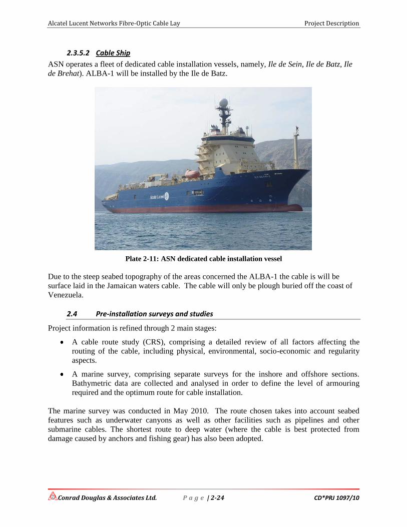
2.3.5.2 Cable Ship
ASN operates a fleet of dedicated cable installation vessels, namely, Ile de Sein, Ile de Batz, Ile
de Brehat). ALBA-1 will be installed by the Ile de Batz.
Plate 2-11: ASN dedicated cable installation vessel
Due to the steep seabed topography of the areas concerned the ALBA-1 the cable is will be
surface laid in the Jamaican waters cable. The cable will only be plough buried off the coast of
Venezuela.
2.4 Pre-installation surveys and studies
Project information is refined through 2 main stages:
A cable route study (CRS), comprising a detailed review of all factors affecting the
routing of the cable, including physical, environmental, socio-economic and regularity
aspects.
A marine survey, comprising separate surveys for the inshore and offshore sections.
Bathymetric data are collected and analysed in order to define the level of armouring
required and the optimum route for cable installation.
The marine survey was conducted in May 2010. The route chosen takes into account seabed
features such as underwater canyons as well as other facilities such as pipelines and other
submarine cables. The shortest route to deep water (where the cable is best protected from
damage caused by anchors and fishing gear) has also been adopted.

Alcatel Lucent Networks Fibre-Optic Cable Lay Project Description
Conrad Douglas & Associates Ltd. P a g e | 2-25 CD*PRJ 1097/10
2.4.1 Cable Route Survey Methodology
MakaiPlan submarine cable planning software (Makai) has been used to generate the proposed
ALBA-1 CRS route included within this study. Makai is a PC software package specifically
designed to assist in cable route planning. A number of external database packages have been
used in conjunction with the Makai software to provide the required cultural information. These
are described below:
Smith and Sandwell (S&S) Bathymetry Database
Admiralty, GUNIO and NOAA Raster Charts
Global Marine Systems Ltd. (GMSL) Cable Database
United Nations Convention on the Law of the Sea (UNCLOS) Maritime Boundaries
Database
United Kingdom Hydrographic Office Wreck Search Database
Extensive Internet Searches
2.4.2 General Overview of Physical Route Survey
2.4.2.1 Combined hydrographic and geophysical survey works including gravity coring and grab sampling
This was conducted for nearshore survey works (0-20 metres water depth) and offshore survey
works (water depths between 20 and 1000 metres). Deep-water swathe bathymetry was
conducted for all water depths greater than 1000 metres.
2.4.2.2 Topographic Survey
At the proposed landing sites a topographic land survey was undertaken to precisely map the
high / low water marks, all features and obstructions to 250m either side (if possible) of the
BMH and 250m inland (if possible) of the BMH.
2.4.2.3 Nearshore / Diver Swim Survey
In the nearshore zone in water depths too shallow for the operation of survey vessels a diver
swim survey was undertaken to ascertain the seabed conditions and positively identify the
location of other in service cables and seabed obstructions.
2.4.2.4 Shallow-water Survey
For shallow-water survey works swathe bathymetry, seabed features and shallow geology
conditions were ascertained to 1000 metres water depth in a survey corridor of 500m. Adequate
seabed samples were collected and analysed, where necessary, to assist in geophysical data
integration

Alcatel Lucent Networks Fibre-Optic Cable Lay Project Description
Conrad Douglas & Associates Ltd. P a g e | 2-26 CD*PRJ 1097/10
Offshore survey works determined the extent of in-service cable crossings in water depths less
than 1000 metres. A magnetometer was used where the cables could not be seen on the other
survey sensors.
2.4.2.5 Deep-water Survey
In water depths greater than 1000 metres bathymetry only is required. The survey corridor was a
minimum of three times the water depth or 10km whichever is the least.
All survey and charting conducted was referenced to WGS84 datum and spheroid, created using
a Mercator projection where possible. Land surveys were conducted on the same Mercator
projection.
2.4.3 Cable Route Engineering
2.4.3.1 General Cable Engineering Considerations
The International Cable Protection Committee (ICPC) Recommendation No.2 (Recommended
Routing and Reporting Criteria for Cables in Proximity to Others) has been used as a primary
reference during the design process of compiling the proposed ALBA-1 route.
Where conditions allow, every attempt has been made to ensure a horizontal separation between
the proposed route and any existing adjacent cables of three times the water depth. This is a
precautionary measure to help ensure the security of the ALBA-1 cable if a fault in another
adjacent cable means that the latter cable needs to be recovered by grappling. Likewise the same
protection is offered to other existing cable systems in the event that an ALBA-1 section requires
recovery for maintenance reasons.
The horizontal separation between cable systems is the subject of Articles 51, 58, 79 and 114
embodied within the United Nations Convention on the Law of the Sea (UNCLOS), which
requires that “it is necessary to give due regard to cables already in position. In particular,
possibilities of repairing existing cables or pipelines shall not be prejudiced.”
At crossings of existing cables it is normally the case that a crossing is designed to be three times
the water depth from the nearest repeater or powered equaliser on the existing cable, wherever
possible.
It is recognised that the ICPC “recommend that 'crossing angles shallower than 45° should not be
implemented in order to ensure operational and maintenance activities related to either cable are
not compromised”.
With existing in-service cable crossings care has been taken to avoid a conflict between
armoured and un-armoured cable types due to the risk of abrasion on the less protected cable.
In an attempt to offer maximum system security to the ALBA-1 system, a proposed route has
been engineered which attains deep water as quickly as possible.

Alcatel Lucent Networks Fibre-Optic Cable Lay Project Description
Conrad Douglas & Associates Ltd. P a g e | 2-27 CD*PRJ 1097/10
In areas of relatively steep slopes it is important not only that the route stays perpendicular to the
slope but also that the number of alter courses is kept to a minimum. This helps provide the
installation vessel with a straight run in / run out and optimises the chance of the cable
touchdown point being in the desired location. This also reduces the surface area of the cable
which would come into contact with material should a sediment slump take place on the slopes
dragging the cable into tension, and ultimate failure. In surface laid sections this action also
minimises the length of cable exposed on the slope and therefore minimises the associated risk of
chafing and suspensions.
2.4.3.2 Cable Types
It is proposed that Alcatel’s OAL-C5 suite of cables will be used on the repeated segment 1 and
URC-2 on the unrepeated segment 2 of the ALBA-1 system. Table 2-4 summarises the cable
types and maximum depth ratings for each type in the OAL-C5 suite and Table 2-5 provides the
same details for the URC-2 suite.
Table 2-4: OAL-C5 Cable Types and Maximum Depth Ratings
Cable Type Maximum Qualified Buried Installation
Depth (m) Maximum Qualified Surface Lay
Installation Depth (m)
Double Armour (DA) 500 500
Single Armour (SA) 2000* 2000*
Light Weight Protected (LWP) 7000
Light Weight (LW) 8000
*SA cable may be used down to 2000m provided that the recovery of the transition to LW or
LWP cable is made from the SA cable where the depth is greater than 1500m.
Table 2-5: URC-2 Cable Types and Maximum Depth Ratings
Cable Type Maximum Qualified Buried Installation
Depth (m) Maximum Qualified Surface Lay
Installation Depth (m)
Double Armour (DA) 500 500
Single Armour (SA) 2000* 2000*
Light Weight Protected (LWP) 6000
Light Weight (LW) 7000
*SA cable may be used down to 2000m provided that the recovery of the transition to LW or
LWP cable is made from the SA cable where the depth is greater than 1500m.
Cable type selection and the depth at which transitions are located (up to maximum qualified
depth) are based on the results of the marine route survey and ASN route engineering guidelines.

Alcatel Lucent Networks Fibre-Optic Cable Lay Project Description
Conrad Douglas & Associates Ltd. P a g e | 2-28 CD*PRJ 1097/10
2.4.3.3 Slack Values, Branching Unit and Beach Cable Allowances
Slack values developed for this project are for total surface slack values which combine 'bottom'
slack (also known as 'contingency slack') and 'infill' slack (due to topography). Values have been
derived in accordance with standard industry practices for 'bottom' slack and measurements of
slopes derived from database bathymetry, as per Alcatel Submarine Networks Route Engineering
Handbook (ref. REH Nov 2009).
“Bottom slack” values are determined principally by water depth as detailed in Table 2-6, with
“infill slack” automatically calculated by the MakaiPlan software.
At the proposed landing, an additional 50m of DA cable type will be added to facilitate landing
operations and BMH cable requirements/spare as per standard REH practice. This is known as
the Shore-End (Beach) Allowance.
Table 2-6: Bottom Slack Values
Water Depth Range Bottom Slack Value
0 –15m 0.8%
15-500m 0.2% Any installation type
500-1500m 0.2% Plough buried areas
0.5% Surface laid areas
1500-2000m 1.0%
> 2000m –av. Slopes <10° 3.0%
> 2000m –av. Slopes 10°-20° 3.5%
> 2000m –av. Slopes >20% 4.0%
2.5 Personnel Requirements
The personnel requirement for this project is fairly small. The bulk of the workforce is comprised
of technical expertise that will be resident aboard the cable laying vessel. As such there is little or
no additional personnel requirement necessary.
The additional manpower required may be in the form:
1. Small boat operator – to operate in inshore waters that does not support the cable laying
vessel
2. Operators of backhoe and other mechanical devices to construct the trench on land for the
cable duct as well as install the pre-constructed beach manhole.
3. A licensed solid waste hauler to remove any solid waste generated such as discarded
packing material and food waste.

Alcatel Lucent Networks Fibre-Optic Cable Lay Project Description
Conrad Douglas & Associates Ltd. P a g e | 2-29 CD*PRJ 1097/10
2.6 Solid Waste Management
Solid waste generated from this proposed project will be disposed of at an approved Dump
Facility It is expected that a private solid waste haulage contractor will be utilized to collect and
disposed of any waste material generated during the cable lay activities.

Alcatel Lucent Networks Fibre-Optic Cable Lay Analysis of Alternatives
Conrad Douglas & Associates Ltd. CD*PRJ 1097/10
ANALYSIS OF ALTERNATIVES

Alcatel Lucent Networks Fibre-Optic Cable Lay Analysis of Alternatives
Conrad Douglas & Associates Ltd. P a g e | 3-1 CD*PRJ 1097/10
3 Analysis of Alternatives
3.1 Introduction
In considering the development options, the following alternative analyses were conducted.
1. The “No-Action” Alternative
2. The Proposed Landing Site Alternatives
3. Technology Alternatives
3.2 The “No-Action” Alternative
The selection of the “No-Action” alternative would mean the discontinuation of project designs
and result in no new additions to Jamaica’s existing telecommunications sector. There are major
socio-economic implications of this alternative to the security and stability of Jamaica’s
telecommunications network.
Though Jamaica now enjoys better external telecommunications, the redundant capabilities of
the system would not be put in place which would result in loss of service should the existing
system be damaged. Any increase in fibre-optic cable connections with the world translates to a
more stable network. Also, Jamaica would not realise the potential connection to South America
which has become a major trading partner. The enormous economic and social development
opportunities for Information Communication Technology (ICT) as well as the investment will
be lost, including the potential for job creation. It therefore would be necessary to consider
alternative methods of meeting data transmission requirements.
The installation of this cable has the potential to translate into lower cost alternatives to
Jamaicans who enjoy the various services such as cable TV, telephone and internet. Without this
project the proposed submarine fibre-optic cable would not be installed. No operations and
maintenance activities would occur. This alternative would not fulfil the purpose of the project or
meet the identified needs for high-speed data transmission throughout Jamaica.
3.3 Proposed Landing Site Alternatives
In consideration of alternatives to the landing site, the proponent investigated various locations
along the north-east coast to land the fibre-optic cable. The decision to look at this section of the
company was primarily in relation to the origin of the spur to Jamaica which is in Cuba.
Three (3) alternative landing sites were considered:
1. St. Ann’s Bay, St. Ann
2. Ocho Rios, St. Ann
3. Tower Isle, St. Mary

Alcatel Lucent Networks Fibre-Optic Cable Lay Analysis of Alternatives
Conrad Douglas & Associates Ltd. P a g e | 3-2 CD*PRJ 1097/10
The landing sites were selected based on a number of factors. Of primary concern was the type
and degree of impact the cable installation would have on the coastal and marine ecology, as
well as the quality and adequacy of locations to receive and house the cable safely.
The sites that were investigated in this report represent the best selections from exhaustive
considerations of a number of sites. Some of which were disqualified on the basis of:
Estimated coastal and marine ecological impacts,
Distance to existing or proposed hubs,
Impacts to and on cable laying installation, and
Through consultations.
3.3.1 Alternative Landing Site #1: St. Ann’s Bay
St. Ann’s Bay provides a fairly good bay area in which to land the cable as follows:
The location does not enjoy any significant marine activity, very few watersport activities
and few fishermen. Limited or no trawl fishing apparent and negligible vessel anchoring
The nearshore is short in distance, less than 1.5 km from shore to deep water
Not within the boundaries of the Ocho Rios Marine Park
In close proximity to a major arterial road
The St. Ann Parish Council lands in the vicinity of the bay were considered for landing the cable.
The site is presently the Department of Motor Vehicle assessment location. The ease in which a
lease or right-of-way agreement could be achieved was considered more tedious than other
locations.
The approach was characterized as having a coarse sand beach with a significant patch reef
protecting the shore (Plate 3-1). Though a sand channel exist, the patch reefs were considered to
be in very close proximity to the channel reducing its width to approximately 100 m.
additionally, small coral heads and a significant seagrass meadow were thought to occupy the
bay and parts of the channel based on aerial image interpretation. Little or no protection appears
to be offered to the bay from the impact of tropical storms and hurricane activities due to the
wide and open nature of the bay. This potential landing site would also represent an area that has
not been impacted by any development activities aside from the seawall to protect the road and
inland resources. The distance to the cable terminal building in Ocho Rios is also less than ideal
since it is more than 7 km away.
The approximate coordinates for the landing site evaluated is: 18° 26’ 20.14” N, 077° 11’
56.97’W

Alcatel Lucent Networks Fibre-Optic Cable Lay Analysis of Alternatives
Conrad Douglas & Associates Ltd. P a g e | 3-3 CD*PRJ 1097/10
Plate 3-1: St. Ann's Bay - Alternative Landing Site #1
3.3.2 Alternative Landing Site #2: Ocho Rios
Ocho Rios provides a fairly good bay area in which to land the cable as follows:
The location enjoys a deep water bay that would accommodate the survey and cable
laying vessel in close proximity to shore
The nearshore is short in distance, approximately 1.5 km from shore to deep water
In close proximity to a major arterial road
In very close proximity to the cable terminal building situated in Ocho Rios
There are few suitable landing sites within Ocho Rios. The harbour is a very active zone with
various watersport equipment, cruise ships and cargo. There are also development plans for the
expansion of the pier. The harbour is subject to periodic maintenance in the form of dredging

Alcatel Lucent Networks Fibre-Optic Cable Lay Analysis of Alternatives
Conrad Douglas & Associates Ltd. P a g e | 3-4 CD*PRJ 1097/10
that could impact the installed cable. The ease in which a lease or right-of-way agreement could
be achieved was considered tedious based on the nature of business along the waterfront.
The harbour has a good deep water approach with few obstructions, however, the nature and type
of activities conducted within the harbour ruled out this option (Plate 3-2). It would require
significant efforts at scheduling to not only conduct the route survey but as lay the cable.
Plate 3-2: Ocho Rios - Alternative Landing Site #2
3.3.3 Alternative Landing Site #3: Tower Isle
Tower Isle provides a fairly good area in which to land the cable as follows:
The location has served as a landing site for fibre-optic cables in the past
It does not enjoy any significant marine activity, very few watersport activities and few
fishermen. Limited or no trawl fishing apparent and negligible vessel anchoring
The nearshore is short in distance, less than 1.5 km from shore to deep water

Alcatel Lucent Networks Fibre-Optic Cable Lay Analysis of Alternatives
Conrad Douglas & Associates Ltd. P a g e | 3-5 CD*PRJ 1097/10
In close proximity to a major arterial road
The ease in which a lease or right-of-way agreement could be achieved was considered to be
fairly straightforward due to the numerous private properties in the area.
The approach was characterized as having a coarse sand beach with a significant patch reef
protecting the coastline (Plate 3-3). Few sand channels exist, the patch reefs is considered to be
in very close proximity to the shore (approximately 500 m) and runs the entire length of the
coastline. The channels are narrow and the inshore has substantial seagrass coverage based on
aerial image interpretation and anecdotal evidence (fishermen). Little or no protection appears to
be offered to the bay from the impact of tropical storms and hurricane activities due to the wide
and open nature of the coast.
The distance to the cable terminal building in Ocho Rios is also less than ideal since it is more
than 7 km away.
Plate 3-3: Tower Isle - Alternative Landing Site #3

Alcatel Lucent Networks Fibre-Optic Cable Lay Analysis of Alternatives
Conrad Douglas & Associates Ltd. P a g e | 3-6 CD*PRJ 1097/10
3.4 Technology Alternatives
A number of technological alternatives that either did not fulfill the purpose of the project or did
not meet the agreed criteria were evaluated. The major factors that affected the acceptability of
those options were potentially adverse environmental effects and problems related to technical
feasibility. The following details the advantages of incorporating a high speed data fibre-optic
cable in Jamaica, when compared with other technologies outlined below:
SPEED: Fibre optic networks operate at high speeds - up into the gigabits
BANDWIDTH: large carrying capacity
DISTANCE: Signals can be transmitted further without needing to be "refreshed" or
strengthened.
RESISTANCE: Greater resistance to electromagnetic noise such as radios, motors or
other nearby cables.
MAINTENANCE: Fibre optic cables costs much less to maintain.
3.4.1 Radio
Other high-speed wireless providers, such as those using 24 GHz, 28 GHz and 38 GHz spectrum,
have concentrated on the more densely populated urban areas because of transmission distance
limitations. Signals using these radio frequencies are generally limited to a one to three-mile
radius, or three to 28 square miles, which makes application in less densely populated areas less
economical. These frequencies are inherently more susceptible to weather and environmental
interference.
The option does not meet the purpose of the project.
3.4.2 Telephony
The telephone industry predominantly uses copper twisted-pair for the delivery of
communications services to commercial and residential customers. Plain old telephone systems
have been the primary means of communicating both locally and long distance. The problem is
that it was designed for the transmission of voice communications. It's a mature technology, but
inadequate by design, the amount of bandwidth that can be delivered is restricted by the
characteristics of the copper twisted-pairs installed between the customer and central office.
Fibre-optics spans the long distances between local phone systems as well as providing the
backbone for many network systems (such as cable television services, university campuses,
office buildings, industrial plants, and electric utility companies).
The main difference is that fibre-optics use light pulses to transmit information down fibre lines
instead of using electronic pulses to transmit information down copper lines.

Alcatel Lucent Networks Fibre-Optic Cable Lay Analysis of Alternatives
Conrad Douglas & Associates Ltd. P a g e | 3-7 CD*PRJ 1097/10
Services such as DSL delivered across a local exchange carrier’s existing copper wire system are
capable of delivering very high speeds. However, DSL suffers performance limitations based on
the distance from the customer premises to the serving central office. Distances are limited to
about four to five miles from a central office for the lowest speed solutions and 10,000 feet or
less for the fastest. Additionally, much of the plant is physically incapable of providing
broadband service.
The option does not meet the purpose of the project.
3.4.3 Satellite Data Transmission
A non-cable option of replacing the proposed telecommunication and data transmission services
is satellite communications. The use of communications satellites to provide the services
identified as necessary would require no construction in the marine environment, but would not
provide the capacity or quality of service proposed under the project.
Satellite networks, such as direct broadcast satellite, currently offer only one-way Internet
access. Upstream access is limited to existing copper telephone lines. Other alternatives like Low
Earth Orbit (LEO) Satellite Systems are not scheduled to be completed for years and have not
proven capable of providing "carrier-class" voice or data services. Fibre optic cables transmit
voice and data traffic with higher reliability and security at a cheaper rate than satellite. While a
satellite call must travel 27,000 miles (35,780 km) from the earth to the satellite and then another
27,000 miles back, a Jamaica to Florida fibre optic call need only travel about 200 miles point-
to-point. At the speed of light this helps to eliminate the delays suffered during a satellite
telephone call.
The option does not meet the purpose of the project.
3.4.4 Fibre-Optic Cable Data Transmission
Fibre optic cabling offers users:
High data rate and wide bandwidth
Immunity to EMI/RFI and lightning damage
No ground loops
Low attenuation (data loss)
Longer distance - 2 and 5 km with Multimode fibre or over 25 km with Single Mode
fibre
Small cable diameter fits anywhere
Light weight
No sparks if cut
No shock hazard
Secure communications

Alcatel Lucent Networks Fibre-Optic Cable Lay Analysis of Alternatives
Conrad Douglas & Associates Ltd. P a g e | 3-8 CD*PRJ 1097/10
Low system cost
Longer life expectancy than copper or coaxial cable
Cabling of the future
The option meets the purpose of the project.
3.5 Cable Lay Activity Alternatives
3.5.1 Cable Pull
There are very few options available to conduct a cable pull. The most cost-efficient and
environmentally acceptable format previously used in Jamaica will be utilized for this cable lay
as indicated in the Project Description section of this report.
The options available are as follows:
Cable pulled from ship to shore without floating the cable
Cable pulled from ship to shore by initially floating the cable
This entails feeding a winch rope through the ducting and attaching it to the cable with a
compression sleeve or sock. As the cable is winched into the ducting the sock tightens its grip on
the cable. On larger cables a cable pusher is used to assist the winch and thus reduce tension in
the cable. The first option assumes alignment is perfect and cable is put in place without any
consideration of the cable in-situ survey. The second option which is considered for this project
allows a cable pulling plan to be initiated during the cable installation. This includes the logistics
of cable let-off/pulling equipment, the location of intermediate access points, splice locations and
the specific responsibilities of each member of the installation team.
3.5.2 Horizontal Directional Drilling vs. Trenching
The proposed cable lay will utilize trenching from the beach to the manhole. Horizontal
Directional Drilling (Guided Boring) is ideal for the underground installation of gas, electric,
water, telecommunication or soil remediation lines - without excavation or trenching. Horizontal
directional drilling ensures minimal or no environmental disruption and is an excellent choice for
installations in diverse rock and soil conditions. However, based on the nature of the site (no
diverse rock or soil type) and the distance required, the cost to secure and operate a directional
drill far outweighs any benefits to be derived. Both options will result in minor sedimentation
issues at the land-water interface. This can be effectively mitigated using existing methods such
as silt screens/curtains among others. No rock impediments were observed at the landing site.
The sand channel in which the cable will be laid is very wide and no directional drilling is
required to bypass the hard rock substrates on either side.

Alcatel Lucent Networks Fibre-Optic Cable Lay Policy, Legislative & Regulatory Framework
Conrad Douglas & Associates Ltd. CD*PRJ 1097/10
POLICY, LEGISLATIVE & REGULATORY
FRAMEWORK

Alcatel Lucent Networks Fibre-Optic Cable Lay Policy, Legislative & Regulatory Framework
Conrad Douglas & Associates Ltd. CD*PRJ 1097/10
4 Policy, Legislative & Regulatory Framework
4.1 Introduction
The policies, legislation, regulations and environmental standards of the Government of Jamaica
(GOJ), which pertain to this development have been researched and analyzed, to ensure that the
project complies with all policy, legal and regulatory requirements. The areas examined
included environmental quality, health and safety, protection of sensitive areas, protection of
endangered species, site selection and land use control at the regional, national and local levels,
which relate to or should be considered within the framework of the project.
All development applications are submitted for approval to the Town & Country Planning
Authority, through the local Parish Council and then forwarded to the relevant authorities
including NEPA and the Environmental Health Unit (EHU) of the Ministry of Health.
NEPA, the governing environmental agency, may require an environmental impact assessment
(EIA) to be considered along with the development plan for the Authority's approval. The EHU
imposes guidelines for air, water and soil standards to be maintained after construction.
In this case, this project triggers an EIA because it falls within the Prescribed Categories (Annex
I) pursuant to Natural Resources Conservation (Permits and Licences) Regulations (Amended)
2004 as described by item 3 – Pipelines and Conveyors for Gas Transport, Underground &
Underwater Cables. This project concerns the laying of underwater cables.
This section serves to address all applicable policies, legislation, standards, and regulations that
may affect this project.
4.2 Applicable Jamaican Policies, Legislations, Standards & Regulations
Legislation relevant to the laying of a Fibre-Optic cable along the seabed of Jamaica’s territorial
waters and terminating at Golden Sands Beach Cottages in the parish of St. Ann is outlined
below.
4.2.1 The NRCA Act, 1991
The NRCA Act (1991) is the overriding legislation governing environmental management in
Jamaica. It requires that all new projects, (or expansion of existing projects), which fall within
prescribed categories be subject to an environmental impact assessment (EIA).
The regulations and the approved Terms of Reference (ToR) require that ten (10) copies of the
EIA Report be submitted to the Authority for review. There is a preliminary review period of ten
(10) days to determine whether additional information is needed. After the initial review the
process can take up to ninety (90) days for approval. If on review and evaluation of the EIA the
required criteria are met, a permit is granted. In the event that the EIA is not approved, there is
provision for an appeal to be made to the Minister.

Alcatel Lucent Networks Fibre-Optic Cable Lay Policy, Legislative & Regulatory Framework
Conrad Douglas & Associates Ltd. CD*PRJ 1097/10
Specifically, the relevant section(s) under the Act which address the proposed project are:
s.10:(1) Subject to the provisions of this section, the Authority may by notice in writing
require an applicant for a permit of the person responsible for undertaking in a prescribed area,
any enterprise, construction or development of a prescribed description or category-
(a) to furnish the Authority such documents or information as the Authority thinks fit;
or
(b) where it is of the opinion that activities of such enterprise, construction or
development are having or are likely to have an adverse effect on the
environment, to submit to the Authority in respect of the enterprise, construction
or development, an EIA containing such information as may be prescribed, and
the applicant or, as the case may be, the person responsible shall comply with the
requirement.
s.18: Enforcement of Controls – threat to public health or natural resources
s.32-33: Ministerial Orders to protect the environment
s.38: Regulations
All the necessary applications have been submitted to the Agency. An application for an
Environmental Permit and License was completed and submitted to NEPA as well as a Project
Information Form (PIF) and Terms of Reference (ToR). The approved ToR for this EIA is
included in the appendix of this document (Appendix I). This EIA document satisfies the
penultimate review process, mandatory public meeting next, before the required licences and
permits can be issued.
Various standards and regulations that apply under this Act are outlined below:
4.2.1.1 The Natural Resources Conservation Authority (Air Quality) Regulations, 2006
These regulations were gazetted on July 12, 2006. This regulation is considered although it was
designed primarily for the quality of the airshed within which an industrial entity is discharging
emissions (gases or particulate matter).
The environmental impact from any air emissions (gasses or particulate matter) will be
influenced by the ambient meteorological conditions within the area, such as wind (speed and
direction), and rain.
Table 4-1 below outlines the ambient air quality standards as issued by NEPA.

Alcatel Lucent Networks Fibre-Optic Cable Lay Policy, Legislative & Regulatory Framework
Conrad Douglas & Associates Ltd. CD*PRJ 1097/10
Table 4-1: Air Quality Standards for Jamaica (NEPA)
Pollutant Averaging Time Standard (maximum concentration in μg/m3)
Total Suspended Particulates Matter (TSP) Annual 60
24 hour 150
PM10 Annual 50
24 hour 150 Lead Calendar Quarter 2
Sulphur Dioxide Annual 80 primary, 60 secondary
24 hour 365 primary, 280 secondary 1 hour 700
Photochemical oxidants (ozone) 1 hour 235
Carbon monoxide 8 hour 10,000
1 hour 40,000 Nitrogen Dioxide Annual 100
The proposed fibre-optic cable installation has the potential to impact on surrounding
commercial and residential receptors particularly during trenching and operation of heavy
equipment. All efforts will be utilised to ensure the project will not result in a significant loss in
air quality within the sphere of influence of the project. The applicable mitigation strategies
outlined further in this report will be monitored during on-site activities to ensure compliance.
4.2.1.2 Noise Standards
Noise Standards for Jamaica have been proposed by NEPA based on the World Bank standards.
The guideline for daytime perimeter noise is 75 decibels and 70 decibels for night-time noise.
Environmental management and monitoring policies will be put in place to monitor noise during
the construction of this development. This will include ensuring that suppliers and contractors
ensure that associated mechanical equipment that may generate noise be fitted with manufacturer
specified silencers and other devices to ensure noise levels do not exceed standards.
4.2.1.3 Protected Areas
The ALBA-1 cable system falls within the eastern border of the Ocho Rios Protected Area. The
Ocho Rios Marine Park was designated in 1999 by a Natural Resources Conservation Order. The
Marine Park designation is not expected to have an adverse impact on the viability of the Ocho
Rios landing and the cable routing because the park is a known mixed use zone.
4.2.2 The Watershed Protection Act, 1963
This Act governs the activities operating within the island’s watersheds, as well as protects these
areas. There are twenty-six (26) watershed management units designated under this Act,
including the White River Watershed Management Unit in which this project falls.

Alcatel Lucent Networks Fibre-Optic Cable Lay Policy, Legislative & Regulatory Framework
Conrad Douglas & Associates Ltd. CD*PRJ 1097/10
Determinations have been made to identify any potential impacts that this project may have on
the watershed and mitigative actions proposed where impacts are identified further in this
document.
It is not anticipated that this project will have any significant adverse environmental impact on
the watershed. The impact area is primarily marine and all efforts have been made to ensure the
route taken is the best available.
4.2.3 The Wildlife protection Act, 1945
This act involves the declaration of game sanctuaries and reserves, game wardens, control of
fishing in rivers, protection of specified rare or endemic species. The Act also provides for the
protection of animals and makes it an offence to harm or kill a species which is protected. It
stipulates that, having in one’s possession “whole or any part of a protected animal living or dead
is illegal. This Act has to be considered for the proposed project.
The ecological assessment has determined that there are species that may be impacted in the
marine environment. A management plan has been outlined to address the avoidance/care of
specified species as necessary.
4.2.4 The Endangered Species (Protection, Conservation and Regulation of Trade) Act (2000)
This Act governs the restriction on trade in endangered species, regulation of trade in species
specified in the schedule, suspension and revocation of permits or certificates, offences and
penalties, and enforcement.
The proponent does not intend to engage in the trade of endangered species.
4.2.5 Water Resources Act, 1995; Underground Water Control Act, 1959
The Underground Water Control Act of 1959 is the legal instrument. However, the Water
Resources Act is expected to provide for the management, protection, controlled allocation and
use of the water resources of Jamaica. Thus, the water quality control for both surface and
groundwater are regulated by this Act.
Any activity that negatively influences the quality of the existing water, whether ground or
surface, would be relevant to this Act. There are no defined activities that are expected to
undermine water resources in the area.
4.2.6 The Clean Air Act, 1964
The Clean Air Act speaks generally to aspects of industrial operations such as the stockpiles,
conveyors and ship loading. This Act also makes reference to the use of inspectors to inspect any
premises, carry out tests, and take samples of any substance that he/she considers necessary or

Alcatel Lucent Networks Fibre-Optic Cable Lay Policy, Legislative & Regulatory Framework
Conrad Douglas & Associates Ltd. CD*PRJ 1097/10
proper for the performance of duties. This development has the potential to discharge particulate
matter to the atmosphere through the use of heavy equipment and the generation of fugitive dust.
However, the impact is anticipated to be negligible.
This project will be regulated by this Act in accordance with the NRCA (Air Quality)
Regulations. The proponent intends to abide by all regulations regarding air quality and intends
to put in place best management practices used in similar operations globally.
4.2.7 The Town and Country Planning Act, 1957
This Act governs the development and land use (excluding agriculture) in specified areas,
through Development Orders, local planning authorities, development planning processes and
Tree Preservation Orders. Under this Act the Town Planning Department is the agency
responsible for the review of any plans involving development. The Act allows for specific
conditions to be stipulated and imposed on any approved plans. The planning decision is based
upon several factors, including;
Location of the development;
Land use and zoning;
Effect of the proposal on amenities, traffic, etc.
4.2.7.1 Development Orders
The Town and Country Planning Act empower the Town and Country Planning Authority to
prepare in consultation with the Local Planning Authority, legal documents called Development
Orders for specific areas throughout Jamaica.
The aim of these documents is to regulate and control the use of land ensuring that land is not
misused. The St. Ann Parish (Confirmed) Development Order (2000) governs development
activities within the parish of St. Ann.
The proposed project falls within the ambit of development activities that may be conducted
within the parish of St. Ann. No conflicts have been identified as a result of this proposed
project. A fibre-optic cable was previously landed at the Shaw Park Beach in 1997 in compliance
with the development order.

Alcatel Lucent Networks Fibre-Optic Cable Lay Policy, Legislative & Regulatory Framework
Conrad Douglas & Associates Ltd. CD*PRJ 1097/10
Figure 4-1: Development Orders of Jamaica
4.2.8 The Jamaica National Heritage Trust Act, 1985
The Jamaica National Heritage Trust, formerly the Jamaica National Trust, administers the Act.
This Act provides for the protection of important areas, including the numerous monuments,
forts, statues, and buildings of historic and architectural importance in Jamaica.
This Act will prove applicable if any structures of archaeological and/or architectural importance
stands to be affected by the proposed site activities or unearthed during site activities. The JNHT
has record of heritage artefacts of significance at this site. The environmental management plan
will also be guided by this Act where any development works that uncovers heritage artefacts
will result in the cessation of operations and the subsequent intervention of the JNHT.
4.2.9 The Public Health Act, 1985
This Act falls under the ambit of the Ministry of Health (MOH) and governs all matters
concerning the handling of food material. In addition, provisions are also made under this Act
for the activities of the Environmental Health Unit (EHU), a division of the MOH. The EHU has
no direct legislative jurisdiction, but works through the Public Heath Act to monitor and control
pollution from point sources. The functions of the unit include:

Alcatel Lucent Networks Fibre-Optic Cable Lay Policy, Legislative & Regulatory Framework
Conrad Douglas & Associates Ltd. CD*PRJ 1097/10
The monitoring of waste water quality, including regular water quality analysis,
using water standards published by NEPA;
Monitoring of occupational health as it relates to industrial hygiene of potentially
hazardous working environments;
Monitoring of air pollutants through its laboratory facilities.
In addition, there are various sections of this legislative instrument which governs and protects
the health of the public. Relevant sections under the Public Health Act of 1985, are Sections 7.-
(1) A Local Board may from time to time, and shall if directed by the Minister to do so, make
regulations relating to (0) nuisances and 14.- (1) The Minister may make regulations generally
for carrying out the provisions and purposes of this Act, and in particular, subject to section 7,
but without prejudice to the generality of the foregoing, may make regulations in relation to (d)
air, soil and water pollution.
It is not anticipated that there will be any significant impact to the water quality of nearshore
waters or land along the route to the cable terminal building via road trenches.
4.2.10 Disaster Preparedness and Emergency Management Act, 1993
The principal objective of the Act is to advance disaster preparedness and emergency
management measures in Jamaica by facilitating and coordinating the development and
implementation of integrated disaster management systems. The project proponents will
establish procedures and guidance documents, as outlined in the environmental management
section of this report, in respect of disaster preparedness and emergency management. These
measures will be tailored, as necessary, with assistance from various agencies.
4.2.11 National Solid Waste Management Authority Act, 2001
The National Solid Waste Management Authority (NSWMA) under this Act has the
responsibility to manage and regulate the solid waste sector. It includes requirements for licences
for operators and owners of solid waste disposal facilities (in addition to permit requirements of
NEPA).
The necessary arrangements for solid waste management and disposal for all solid waste
generated from this proposed project will be implemented. Where possible, the project will
recycle.
4.2.12 Occupational Safety & Health Act, 2003 (Draft)
This Act oversees the prevention of injury and illness resulting from conditions at the workplace,
the protection of the safety and health of workers and the promotion of safe and healthy
workplaces.
Sampling of sections from the Draft Act that are relevant to this project, include:

Alcatel Lucent Networks Fibre-Optic Cable Lay Policy, Legislative & Regulatory Framework
Conrad Douglas & Associates Ltd. CD*PRJ 1097/10
4. (1) This Act applies to all branches of economic activity and to all owners, employers and
workers in all such branches.
18. (1) Provides a description of the duties of employers, outlining the need for quality work
areas and work environments, procedures and guidelines that will result in safe and healthy
workplaces.
19. (1) discusses the duties of employers at construction sites in terms of employee safety and
health during work activities.
25. (1) an employer shall make or cause to be made and shall maintain an inventory of all
hazardous chemicals and hazardous physical agents that are present in the workplace.
26. (1) this section provides guidelines and procedures for employers to follow in terms of
identification of hazardous chemicals. This includes labelling and identification protocols.
30. (1) Basically, this section of the Act requires an employer to provide training of its
employees with a potential for exposure to hazardous chemicals or physical agents.
It is expected that this Draft Act will be Gazetted in the near future. The project proponent has an
understanding and appreciation for the contents of this policy. Occupational safety and health
policies will be extended to this project as outlined in the environmental management section of
this report.
4.3 International Policies
4.3.1 Agenda 21
In June 1992, Jamaica participated in the United Nations Conference for Environment and
Development (UNCED) in Rio de Janeiro, Brazil. One of the main outputs of the conference was
a plan of global action, titled Agenda 21, which is a “comprehensive blueprint for the global
actions to affect the transition to sustainable development” (Maurice Strong). Jamaica is a
signatory to this Convention. Twenty seven (27) environmental principles were outlined in the
Agenda 21 document. Those most relevant to this project, which Jamaica is obligated to follow
are outlined below:
Principle 1: Human beings are at the centre of concerns for sustainable development.
They are entitled to a healthy and productive life in harmony with nature.
Principle 2: States have, in accordance with the Charter of the United Nations and the
principles of international law, the sovereign right to exploit their own resources pursuant
to their own environmental and developmental policies.
Principle 4: In order to achieve sustainable development, environmental protection shall
constitute an integral part of the development process and cannot be considered in
isolation from it.

Alcatel Lucent Networks Fibre-Optic Cable Lay Policy, Legislative & Regulatory Framework
Conrad Douglas & Associates Ltd. CD*PRJ 1097/10
Principle 10: Environmental issues are best handled with the participation of all
concerned citizens, at the relevant level. At the national level, each individual shall have
appropriate access to information concerning the environment that is held by public
authorities, including information on hazardous materials and activities in their
communities, and the opportunity to participate in decision-making processes.
Principle 15: In order to protect the environment, the precautionary approach shall be
widely applied by States according to their capabilities. Where there are threats of serious
or irreversible damage, lack of full scientific certainty shall not be used as a reason for
postponing cost-effective measures to prevent environmental degradation.
Principle 16: National authorities should endeavour to promote the internationalisation of
environmental costs and the use of economic instruments, taking into account the
approach that the polluter should, in principle, bear the cost of pollution, with due regard
to the public interest and without distorting international trade and investment.
Principle 17: Environmental impact assessment, as a national instrument, shall be
undertaken for proposed activities that are likely to have a significant adverse impact on
the environment and are subject to a decision of a competent national authority.
The project proponents are cognisant of and will abide by the international treaties and protocols.
The principles of Agenda 21 that relate to this project will be applied throughout the project
lifespan as necessary.
4.3.2 United Nations Convention on the Law of the Sea
The United Nations Convention on the Law of the Sea lays down a comprehensive regime of law
and order in the world's oceans and seas establishing rules governing all uses of the oceans and
their resources. It enshrines the notion that all problems of ocean space are closely interrelated
and need to be addressed as a whole. Jamaica is a signatory to and has ratified this treaty.
The Convention comprises 320 articles and nine annexes, governing all aspects of ocean space,
such as delimitation, environmental control, marine scientific research, economic and
commercial activities, transfer of technology and the settlement of disputes relating to ocean
matters.
Some of the key features of the Convention that applies to this project are as follows:
Coastal States exercise sovereignty over their territorial sea which they have the right to
establish its breadth up to a limit not to exceed 12 nautical miles; foreign vessels are
allowed "innocent passage" through those waters

Alcatel Lucent Networks Fibre-Optic Cable Lay Policy, Legislative & Regulatory Framework
Conrad Douglas & Associates Ltd. CD*PRJ 1097/10
Ships and aircraft of all countries are allowed "transit passage" through straits used for
international navigation; States bordering the straits can regulate navigational and other
aspects of passage
Archipelagic States, made up of a group or groups of closely related islands and
interconnecting waters such as Jamaica, have sovereignty over a sea area enclosed by
straight lines drawn between the outermost points of the islands; all other States enjoy the
right of archipelagic passage through such designated sea lanes
Coastal States have sovereign rights in a 200-nautical mile exclusive economic zone
(EEZ) with respect to natural resources and certain economic activities, and exercise
jurisdiction over marine science research and environmental protection
All other States have freedom of navigation and over flight in the EEZ, as well as
freedom to lay submarine cables and pipelines

Alcatel Lucent Networks Fibre-Optic Cable Lay Description of the Environment
Conrad Douglas & Associates Ltd. CD*PRJ 1097/10
DESCRIPTION OF THE ENVIRONMENT

Alcatel Lucent Networks Fibre-Optic Cable Lay Description of the Environment
Conrad Douglas & Associates Ltd. P a g e | 5-1 CD*PRJ 1097/10
5 Description of Bio-Physical Environment
5.1 Introduction
The project site is located within St. Ann adjacent its border with St. Mary at White River. The
landing site is a reserved strip of white sand beach to the west of the mouth of the White River.
This beach is primarily used by guest of the Golden Sands Beach Cottages. However, fishermen
and marine interest in the area utilise the eastern end of the beach for docking especially as it
relates to offering services to guest of Shaw Park Beach hotel, which is east and adjacent to the
Golden Sands Beach Cottages Property.
A fibre-optic cable was previously landed at this beach in 1997. Currently there is little or no
evidence of the cable in the environment being that is was buried in a trench across the property
to the roadway (<120 m) and has buried itself in the marine environment over the years.
This landing site is typical of white sand beaches along Jamaica’s north-coast. The impact zone
is very minute. There are no vegetated areas between the beach and the roadways that stand to be
impacted negatively. The environmental setting of the project site and immediate environs were
assessed to determine the existing status of environmental resources prior to the laying of the
cable. Aspects of the environment that were evaluated, were selected on the basis of the
likelihood of the project impacting on these resources, and are discussed in full in this section of
the document.
This section is informed in part by work done by various associates and agencies.
5.2 Physical Environment
5.2.1 Meteorology
Jamaica is surrounded by the Caribbean Sea and is located in the Tropics at approximately
latitude 18ºN and longitude 77ºW. Among the most important climatic influences are the
Northeast Trade Winds, the range of mountains which runs east-southeast to west-southwest
along the centre of the island, the warm waters of the Caribbean Sea, and weather systems such
as upper- and low-level low-pressure centres, troughs and cold fronts.
The cold fronts, usually weak after migrating from the North American continent, are evident
from mid-October to mid-April; whilst the Tropical Weather Systems, namely Tropical Waves,
Tropical Depressions, Tropical Storms and Hurricanes occur from April to December. The
official hurricane season is from June to November.
Much of this data is provided by the Meteorological Office1.
1 Jamaica Meteorological Service, Climatological Data, Sangster International Airport

Alcatel Lucent Networks Fibre-Optic Cable Lay Description of the Environment
Conrad Douglas & Associates Ltd. P a g e | 5-2 CD*PRJ 1097/10
While there are variations in the weather patterns between the north and south coasts of the
island, it is not envisioned that any of the parameters assessed in this section will have any
negative impacts on this project.
5.2.1.1 Rainfall
Rainfall is the most variable of the climatic parameters exhibiting a bimodal nature. The thirty
(30) year (1951-1980) average monthly rainfall values highlights the typical rainfall pattern for
the region (Figure 5-1). The driest period runs from December to March and is associated with
cold fronts migrating from North America. There are two distinct wet seasons, May to June and
September to November occurring as regular yearly cycles.
Figure 5-1: Jamaica 30 Year Rainfall Mean (1951-1980)
Of the weather parameters, rainfall is the most variable. Islandwide, during the period 1951 to
1980, annual rainfall ranged from a maximum of 2593 mm (102.09 in) in 1963 to a minimum of
1324 mm (52.13 in) in 1976, with an average of 1940 mm (76.38 in) annually. The hundred-year
(1881-1990) mean annual rainfall is 1895 mm (74.61 in). Historically, the wettest year on record
was 1933 with an annual rainfall of 2690 mm (116.54 in) whilst the driest year was 1920 with an
annual rainfall of 1299 mm (51.14 in). Figure 5-2 shows the mean long-term mean rainfall for St.
Ann for 1951-1980.
Weather during the dry or rainy season along with other rain-producing systems are influenced
by the sea breeze and orographic effects which tend to produce short-duration showers, mainly
during mid-afternoon.
The parish of St. Ann receives an annual average of 1596 mm of rainfall per year mainly during
the rainy period, between the months of May and November. The driest period occurs from
January through March, with less than 75 mm per month.

Alcatel Lucent Networks Fibre-Optic Cable Lay Description of the Environment
Conrad Douglas & Associates Ltd. P a g e | 5-3 CD*PRJ 1097/10
Figure 5-3 shows the yearly rainfall totals for the two (2) closest rain stations to the proposed
landing site for the period 2000 to 2009. The data shows average annual rainfall for the period
2000-2009 to be 1885 mm and 1934 mm respectively for Cole Gate and Industry. Both stations
are within 6 km of the proposed landing site.
Figure 5-2: St. Ann Long-Term Mean Monthly Rainfall (mm) - 1951-1980
Yearly rainfall totals for selected locations for the period
0
500
1000
1500
2000
2500
3000
2000 2001 2002 2003 2004 2005 2006 2007 2008 2009
Year
Rai
nfa
ll (m
m)
COLE GATE
INDUSTRY
Figure 5-3: Yearly rainfall totals for Cole Gate and Industry in the parish of St. Ann [both stations are within
6 km of the proposed landing site]

Alcatel Lucent Networks Fibre-Optic Cable Lay Description of the Environment
Conrad Douglas & Associates Ltd. P a g e | 5-4 CD*PRJ 1097/10
5.2.1.2 Wind
The daily wind pattern is dominated by the Northeast Trades. During the day, on the North
Coast, the sea breeze combines with the Trades to give an east-north-easterly wind at an average
speed of 15 knots (17 miles per hour). In the period December to March, however, the Trades are
lowest and the local wind regime is a combination of trades, sea breeze, and a northerly or north-
westerly component associated with cold fronts and high-pressure areas from the United States.
By night, the trades combine with land breezes which blow offshore down the slopes of the hills
near the coasts. As a result, on the North Coast, night-time winds generally have a southerly
component with a mean speed of 5 knots (6 miles per hour). By day, from June to July, mean
onshore winds often reach a maximum of up to 23 knots (26 miles per hour) along the North
Coast during mid-afternoon.
Specific wind data was not available for the project area. The closest available data that could be
considered reliable was from the Sangster International Airport in Montego Bay which is
approximately 27 km (17 miles) to the west of the project area.
5.2.1.3 Temperature & Relative Humidity
Apart from rapid fluctuations associated with afternoon showers and/or the passage of frontal
systems, the island's temperatures remain fairly constant throughout the year under the
moderating influence of the warm waters of the Caribbean Sea.
In coastal areas, daily temperatures average 26.2 degrees Celsius (79.2ºF), with an average
maximum of 30.3ºC (86.5ºF) and an average minimum of 22.0ºC (71.6ºF). The warmest months
are June to August and the coolest December to February. Night-time values range from 18.9 to
25.6ºC (66 to 78.1ºF) in coastal areas.
Variations of sunshine from month to month in any area are usually small, approximately one
hour. Differences, however, are much greater between coastal and inland stations. Maximum
day-length occurs in June when 13.2 hours of sunshine are possible and the minimum day-length
occurs in December when 11.0 hours of sunshine are possible.
Afternoon showers are the major cause of most daily variations in relative humidity. Highest
values recorded during the cooler morning hours near dawn, followed by a decrease until the
early afternoon when temperatures are highest.
Although relative humidity in coastal areas average 84% at 7 a.m., temperatures at this time are
in the mid 20's (ºC), therefore, little or no discomfort results. At 1 p.m. the average relative
humidity on the coasts is 71%.

Alcatel Lucent Networks Fibre-Optic Cable Lay Description of the Environment
Conrad Douglas & Associates Ltd. P a g e | 5-5 CD*PRJ 1097/10
5.2.2 Geological Resources
Elevations at the site increase gently from sea level along the shoreline to a maximum of 1.5
metres above sea level along the White River to Ocho Rios main road. The site is approximately
5 km east of Ocho Rios.
The beach is made primarily of white sand originating primarily from the coral reefs along the
coast. Inland of the beach the soil consists of soft sand with intermittent silty-clay deposits.
There is a minimal potential for erosion of soil materials at the site. The topsoil is on strong
bedrock of limestone, possibly from the Hopgate Formation. The distance to the old road from
the high tide mark is approximately 120 m.
The seabed is composed of sand and deposits of silty-clay brought down by the White River. The
river has carved a fairly wide channel that shows overlapping layers of sand and silty clay on top
of a hard rock substrate.
Figure 5-4: Geological Map of St. Ann Parish [Source: Geological Society of Jamaica]
5.2.2.1 Bathymetry
The inshore has a relatively, consistent declining slope substrate of white calcareous sand from
near shoreline to approximately 800 m offshore. The area is made-up of soft sandy substrate.

Alcatel Lucent Networks Fibre-Optic Cable Lay Description of the Environment
Conrad Douglas & Associates Ltd. P a g e | 5-6 CD*PRJ 1097/10
Though a small fringing coral reef is in close proximity, the route alignment proposed will not
infringe on this important ecosystem as it will be laid on the sandy channel bottom.
5.2.3 Hydrogeology & Groundwater Resources
The proposed landing site falls within a coastal aquiclude. This is a formation that does not
transmit water and does not yield water readily to wells and springs. There is no potential for
water resources development at Golden Sands Beach Cottages.
Figure 5-5 below outlines the hydrostratigraphic map of a section of the parish of St. Ann
showing the hydrostratigraphic reference for the proposed landing site.

Alcatel Lucent Networks Fibre-Optic Cable Lay Description of the Environment
Conrad Douglas & Associates Ltd. P a g e | 5-7 CD*PRJ 1097/10
Figure 5-5: Extract from the Hydrostratigraphy Map of Jamaica produced by the Water Resources
Authority (WRA)

Alcatel Lucent Networks Fibre-Optic Cable Lay Description of the Environment
Conrad Douglas & Associates Ltd. P a g e | 5-8 CD*PRJ 1097/10
5.2.4 Natural Hazard Vulnerability and Risks
5.2.4.1 Earthquakes & Landslides
The ALBA-1 cable system is at risk of damage from seismic activity owing to the fact that it
crosses two plate boundaries and because the landings are all in earthquake prone locations. This
risk can be minimised by:
optimal cable routing to avoid crossing side slopes - this minimises the cables risk of
damage as a result of debris flows and avalanches
careful design of slack in the cable system
ensuring maximum cable armouring is applied in high risk areas
earthquake “proofing” of all land structures and ducting
Golden Sands Beach is situated in a moderate earthquake zone in terms of frequency. Between 4
and 5 earthquake events of intensity greater than six (VI; Modified Mercalli Scale) have been
reported in this fault area between 1874 and 1978. The probability of intensity VII was 0.39 for
the period 1686 – 1986. However, it should be noted that there have been previous cable
landings in this area without any adverse impacts due to the effect of earthquakes or other natural
disasters. The risk of landslides is remote.
Figure 5-6 below highlights the concentration of earthquakes around the edge of the Caribbean
plate boundary. Figure 5-7 outlines a close up for Jamaica.

Alcatel Lucent Networks Fibre-Optic Cable Lay Description of the Environment
Conrad Douglas & Associates Ltd. P a g e | 5-9 CD*PRJ 1097/10
Figure 5-6: Map of significant earthquakes between 1973 and 2009 (scale – depth in meters) [(Source:
http://neic.usgs.gov/neis/epic/epic_rect.html)]
Figure 5-7: Map of significant earthquakes between 1973 and 2009 (scale – depth in meters) [(Source:
http://neic.usgs.gov/neis/epic/epic_rect.html)]
Proposed Cable Land at Shaw Park Beach, St. Ann

Alcatel Lucent Networks Fibre-Optic Cable Lay Description of the Environment
Conrad Douglas & Associates Ltd. P a g e | 5-10 CD*PRJ 1097/10
5.2.4.2 Hurricanes & Storm Surge Potential
Hurricanes are a serious seasonal threat from June to November; since 1886, 21 hurricanes have
made landfall in Jamaica, while over 100 have passed within 240 km (150 miles) of the island.
Tsunamis are also a major risk.
Considerations have been given to issues related to storm water and potential for erosion during
the construction and operational phases of the development. As such, a storm water management
system, involving the use of drains, retention ponds and/or absorption pits has been
recommended.
Using Sangster International Airport in Montego Bay as a reference point location: 18.50N
77.92W, all recorded tropical storm and hurricane activity over a period of 100 years are
considered to estimate any trends related to the hurricane activity and the return period of such
activities to the island2. This can be done confidently as Jamaica is a small island and is likely to
be affected wholly regardless of the point of approach of a tropical depression or storm system.
So far this year, no hurricanes have affected the island neither during 2009. However, the island
was last affected during the 2008 cycle by Hurricane Gustav a tropical storm which crossed the
island along the southern parishes. No significant storm surge activity was recorded along the
north coast from this event. Storm surge is not considered a major problem at the proposed. It
should be reiterated here that the cable is projected to be landed prior to the onset of the 2011
hurricane season. The 50 year return period for hurricane winds for the Montego Bay (the closest
area modelled) is 49 m/s. This prediction is based on the TAOS predictions for storm surge for
the “50-year return storm” by the Caribbean Disaster Management Programme project (1999).
Analyses of tropical systems passing within 60nm (= 60mi.) of the island is shown below.
Latitude/longitude coordinates (18.50N, 77.92W) used is for Sangster International Airport, one
of the island weather stations. Figure 5-8 shows whether there are more storms lately or which
5-year period in the last 60+ years was most active.
Figure 5-9 highlights the storm track and intensity of storm activity (hurricanes and tropical
storms) within 60 miles of Jamaica for the period 2000-2008.
2 StormCarib – Caribbean Hurricane Network http://stormcarib.com/climatology/

Alcatel Lucent Networks Fibre-Optic Cable Lay Description of the Environment
Conrad Douglas & Associates Ltd. P a g e | 5-11 CD*PRJ 1097/10
1944 - 2006
Most active 5 year period since 1944:
Most storms: 2000-2004 (4)
Most hurricanes: 2000-2004 (2)
Most severe hurricanes: 1980-1984, 1985-1989, 2000-2004, 2005 only (1)
category 3-5 hurricanes: green; category 1-2: blue; tropical storms: yellow
1944 - 2006
Most active 5 year period since 1944:
Most storms: 2000-2004 (4)
Most hurricanes: 2000-2004 (2)
Most severe hurricanes: 1980-1984, 1985-1989, 2000-2004, 2005 only (1)
category 3-5 hurricanes: green; category 1-2: blue; tropical storms: yellow
Figure 5-8: Hurricane Activity for the Period 1944-2006
3
3 StormCarib – Caribbean Hurricane Network http://stormcarib.com/climatology/MKJP_dec_isl.htm

Alcatel Lucent Networks Fibre-Optic Cable Lay Description of the Environment
Conrad Douglas & Associates Ltd. P a g e | 5-12 CD*PRJ 1097/10
Figure 5-9: Hurricane & Tropical Storms that have passed within 60 mi. of Jamaica during the period 2000-20084
4 http://csc-s-maps-q.csc.noaa.gov/hurricanes/viewer.html

Alcatel Lucent Networks Fibre-Optic Cable Lay Description of the Environment
Conrad Douglas & Associates Ltd. P a g e | 5-13 CD*PRJ 1097/10
5.2.4.2.1 Scour
Scour is a lowering of the seabed below a previously determined equilibrium level, due to a
localized divergence in the transport rate, around marine structures. Scour can jeopardize the
integrity of the installation, where wave and current forces erode sediment.
For many seafloor structures scour is a hazard, for cables it is can often be beneficial. Cables can
settle into the seabed due to their own weight aided by scouring of sediment from around the
cable by waves and currents.
Cables are of a sufficiently high density (2.8-4.2 kgm-3
) to self-bury into the sediment. However,
the self-burial by scour is of the order of one to three times the cable diameter, i.e. relatively
small but this can help reduce the risk of damage.
Movement of the cable on the seafloor, by current or wave action causes abrasion. It is
recommended that, in the surf zones, additional cable protection measures, such as articulated
split pipe, be considered. With the addition of split pipe the density of cable is increased to
approximately 6.0 kgm-3
. With the density of the cable increased the movement of the cable by
wave action is drastically decreased, thereby limiting abrasion and risk of damage to the cable.
5.2.4.3 Riverine & Flash Flooding
Assessing whether an area is prone to flooding or not, not only requires a hydrostratigraphic
assessment of the area (as presented earlier), but also the collection of physical data such as
rainfall run-off patterns, topography and information obtained from actual flooding events
(especially as perceived by individuals who reside or frequent the area during such events) over a
statistically appreciable period. Such information is not readily available from relevant statutory
agencies in a compiled an organized format and is beyond the scope of this Environmental
Impact Assessment. However, broad conclusions may be drawn from what is available,
including informal reports of flooding, or the absence thereof.
It is estimated that the proposed landing site is located in an area where the soil is permeable to
semi-permeable. Permeability or semi-permeability of the areas implies that water should
percolate through the ground and drain into the underlying aquifers or aquicludes. Hence, in the
absence of extreme weather conditions, namely heavy consistent and prolonged rainfall, the
mentioned areas should not flood readily.
No incidence of flash flooding is known to occur at this location
5.2.4.4 Damage to Cable & Damage from Cable
Based on the medium of operation (water) the cable is likely to be affected by any wave action
that is generated from aggressive deep water movement due to storm surges and tectonic activity.
Extreme occurrences of either of these events could cause unlikely cable failure through abrasion
and or instantaneous or gradual extension of the cable beyond the elastic limits of its component

Alcatel Lucent Networks Fibre-Optic Cable Lay Description of the Environment
Conrad Douglas & Associates Ltd. P a g e | 5-14 CD*PRJ 1097/10
materials. However, as with every event, there is a threshold required for noticeable occurrence
and also a limit at which the event will cause unfavourable results; therefore, it is arbitrary to
assume that any storm surge or tectonic activity will cause any unlikely cable failure. Although
there is no pragmatic way to define exactly what level of displacement in the sea floor (vertical
and horizontal) or what type of storm surge will generate a certain definable stress on the cable,
it is statistically possible to conclude from Table 5-1 that both abrasion and tectonic activity
rarely causes cable failure. Implicit in the data, is the fact that these events rarely generate the
forces required to exceed the limits of the cable materials’ strength. Therefore, one can assume
that the combined material strength of the cable materials have been designed to withstand
common abrasion forces resulting from water movement, and the effects of common minor plate
movement. Keep in mind that there are miles of this type of cable deployed worldwide under a
wide variety of marine and seismic conditions that are fully functional.
The deep shore aspect of the cable operations can be generally regarded as unaffected by storm
surges. Storm surges do not usually disturb the ocean bottom in deep waters by virtue of deep
water depth in relation to the volume of water that is displaced. However, pronounced effects are
estimated as likely for near-shore operations as the cable makes the transition to onshore
operations. However, as stated earlier, it is difficult to correlate storm surge magnitude with
sustainable cable integrity – one can only assume that cable breakage is unlikely to occur due to
the design and established track record of the industry. Cable breakage is unlikely in and of itself
to result in environmental degradation or negative environmental impacts.
Table 5-1: Percentage of Failure Causes for 380 Reported Cable Faults
Cause Count %
Abrasion 18 4.7%
Anchor 49 12.9%
Branching Unit 2 0.5%
Cable or Survey Ship Activity 5 1.3%
Dredging/Drilling and Pipe Installation 12 3.2%
Earthquake or Seabed Movement 10 2.6%
Equaliser 1 0.3%
Fatigue 1 0.3%
Fishing Activity 184 48.4%
Impact by Hard Object 5 1.3%
Insulation Failure 3 0.8%
Jointing Box 5 1.3%
Manufacturing Defect - Cable 4 1.1%
Repeater 17 4.5%
Unknown - Cable Deliberately Cut 1 0.3%
Unknown - Cable Mauled 6 1.6%
Unknown - Cable not repaired 1 0.3%
Unknown - Fibre Attenuation 5 1.3%
Alcatel Lucent Networks Fibre-Optic Cable Lay Description of the Environment
Conrad Douglas & Associates Ltd. P a g e | 5-15 CD*PRJ 1097/10
Cause Count %
Unknown - Kinks, Twists, Loops 9 2.4%
Unknown - Shunt Fault 31 8.2%
Unknown - Tension Break 11 2.9%
TOTAL 380
5.2.5 Fishing Related Risks
Various fishing efforts such as trawling, bottom set gillnetting, bottom long lining, and purse
seining are responsible for the majority of cable faults caused by fishing. Bottom trawling is
believed responsible for the largest number of fishing related cable faults and represents the most
substantial fishing hazard to cables. Bottom set gill nets and longlines represent a minor hazard
since the gear, composed of relatively light breaking strength materials, generally does not
penetrate the seabed much. Purse seines, if used with lightweight grapple anchors, could foul on
the bottom. Survey and installation operations may also be affected by the fishing methods.
In Jamaica commercial fishing by vessels that are of a size to pose a serious threat to a cable
system work almost exclusively on the Pedro and Morant Banks and therefore large fishing
vessels do not pose a threat to the ALBA-1 cable system landing at Golden Sands Beach in the
Parish of St. Ann on the north-coast. Additionally the bottom trawling method is reported as only
being actively used off the south coast of Jamaica. Small-scale (using vessels less than 8.4m
long) commercial fishing is active along the north coast of Jamaica and this includes the hook
and line method. Small scale and artisanal fishing does not represent a hazard to the installed
cable; however it may affect the cable route survey and subsequent cable installation.
For the duration of the cable route survey all marine interest were informed, particular fishermen
from the White River fishing community. No incidences were reported and mutual, daily
informed dialogue took place. This procedure will be repeated once approval has been received
for the installation of the cable. Continued liaison with the Fisheries Department (Ministry of
Agriculture) and local fishermen will ensure no incidences occur. In shallow water off the
Jamaican coast the low threat from fishing activities means additional mitigation measures are
not deemed necessary to protect the ALBA-1 cable system from fishing related threats.
5.2.6 Marine and Land Traffic Analysis
The closest port to the Jamaican Segment 2 landing is the Port of Ocho Rios to the west. There is
only one charted designated anchorage area in the vicinity of the ALBA-1 cable system on the
Jamaican coastline. This is within the area covered by the Ocho Rios Port Authority and is of
sufficient distance from the ALBA-1 cable route. It does not represent a threat to the ALBA-1
cable.

Alcatel Lucent Networks Fibre-Optic Cable Lay Description of the Environment
Conrad Douglas & Associates Ltd. P a g e | 5-16 CD*PRJ 1097/10
There is no consideration for land traffic because the extent of this assessment involves laying
the cable in the marine environment and subsequent termination into a beach manhole just
outside the hotel property on the old north-coast roadway.

Alcatel Lucent Networks Fibre-Optic Cable Lay Description of the Environment
Conrad Douglas & Associates Ltd. P a g e | 5-17 CD*PRJ 1097/10
5.3 Biological Environment
5.3.1 Introduction
Alcatel-Lucent Submarine Networks (ASN) intends to deploy a fibre-optic cable on the seafloor
between Venezuela and Cuba, a leg of which will transit the Jamaican island shelf and make
landfall at Golden Sands Beach in Ocho Rios.
An alteration has been proposed for a previously submitted route (Plate 5-2) for the Alcatel-
Lucent Submarine Networks (ASN) fibre-optic cable into Shaw Park Beach in Ocho Rios. The
rationale for the newly proposed route was that it was found more environmentally conservative,
efficient and economical for ASN to implement the cable lay. The proposed alterations to the
route to be taken by the cable over the north coast island shelf are outlined on Plate 5-1 below.
Plate 5-1: Newly Proposed Route

Alcatel Lucent Networks Fibre-Optic Cable Lay Description of the Environment
Conrad Douglas & Associates Ltd. P a g e | 5-18 CD*PRJ 1097/10
Plate 5-2: Previously Proposed Fibre Optic Cable Routing for landing at Shaw Park Beach – Ocho Rios (A-
proposed alignment)
Further to the investigations carried out in June 2010, field investigations for the marine
assessment of the seafloor environment were carried out on the newly proposed cable route,
along with a representative section of adjoining marine environment. This was conducted in
October 2010.
The purpose of the assessment was to determine whether or not there were any sensitive or
otherwise important marine resources that could be impacted by the deployment of the marine
cable. In addition, the assessment served as a basis for the development of any mitigative actions
that would be required to ensure an environmentally sound deployment. The study area in which
the assessment was carried is shown in Plate 5-3.

Alcatel Lucent Networks Fibre-Optic Cable Lay Description of the Environment
Conrad Douglas & Associates Ltd. P a g e | 5-19 CD*PRJ 1097/10
Plate 5-3: Google Earth Image With Overlaid Route of Previously Proposed Fibre-optic Cable Route and
Landing Area at Shaw Park Beach (A), Currently Proposed Route (B) and Study Area (box).
5.3.2 Methods
5.3.2.1 Marine Environment Characterization
Air photo interpretation techniques were utilized to characterize marine substrate/life-form
differences and their spatial extents. The baseline information used for interpretation was as
represented on GoogleEarth images of the study area (defined in Plate 5-3). The GoogleEarth
images were geo-referenced to the JAD 2001 projection/coordinate system and manipulated
using Mapmaker Pro GIS software prior to being interpreted.
Following the initial characterization of GoogleEarth images, ground truthing was conducted
with the aid of SCUBA, with video being the primary tool for field data capture. Data collection
efforts were focused initially around obtaining videos along the proposed cable alignment.

Alcatel Lucent Networks Fibre-Optic Cable Lay Description of the Environment
Conrad Douglas & Associates Ltd. P a g e | 5-20 CD*PRJ 1097/10
Waypoints for the alignment were plotted into a Garmin Global Positioning System (GPS),
which was used as a navigation aid by a supporting dive boat. The dive team used the dive boat
as a reference for underwater navigation along the proposed alignment. Video information was
captured of the entire proposed cable alignment, extending from the point where the cable
intersected the island shelf (at a depth of approximately 40 meters) to shore.
Following the verification of the character of the seafloor along the cable route, 6- 33 meter long
video transects were distributed over hard substrate areas interpreted from the GoogleEarth
images. The transects were initially used for the capture of information on fish populations
existing within the study area using video aided fish assessment methods devised by the Atlantic
and Gulf Rapid Assessment project5 (see Plate 5-4 below).
Plate 5-4: Photographic Description of Video-Aided AGRRA Fish Assessment method
Immediately following this, the same transects were used to guide the capture of vertically
oriented video information for the benthic lifeforms existing within the area, using methods
5 www.agrra.com

Alcatel Lucent Networks Fibre-Optic Cable Lay Description of the Environment
Conrad Douglas & Associates Ltd. P a g e | 5-21 CD*PRJ 1097/10
designed for the Caribbean Planning and Adaptation to Climate Change project6 (see Plate 5-5
below)7.
Plate 5-5: Photographic Description of CPACC Benthic Data Capture Method
Further, vertically oriented still photography techniques were used for the assessment of life-
forms existing within areas interpreted as having soft substrates along the alignment of the
proposed cable, with representative 1x1 m PVC quadrat frames being used for the estimation of
densities of life-forms found within this area. Mapmaker Pro was used to generate a 10 cm x 10
cm grid over each of the quadrats photographed. A random selection of 20 of the 100 10 cm x10
cm grids within each quadrat was then examined and individual shoots counted. Simple
proportion calculations were then used to extrapolate numbers up to the total area of the quadrat.
All vertically oriented images obtained for benthic resources assessments were analysed with the
assistance of CPCE8 and Mapmaker Pro software.
6 www.cpacc.com
7 Video-based assessments of hard substrate areas within the study box were limited due to the fact that the dive
team had to coordinate in-water work with a survey vessel that was utilizing high energy SONAR for bathymetric surveys. The SONAR generated by the equipment would have been hazardous to the dive team. A total of 6-33 meter long transects were surveyed. 8 www.nova.edu/ocean/cpce/index.html

Alcatel Lucent Networks Fibre-Optic Cable Lay Description of the Environment
Conrad Douglas & Associates Ltd. P a g e | 5-22 CD*PRJ 1097/10
5.3.2.2 Water Quality
Three sets of water samples were obtained within the water column along the alignment of the
proposed fibre-optic cable. These samples were analysed for turbidity, total suspended solids,
temperature and pH.
5.3.2.3 Oceanography
Research work done in the Kingston Harbour9 has suggested that there are three primary engines
for water movement within the embayed marine environment. These are:
1. Wind-induced movement
2. Tidally-induced movements
3. Water Density – related movements
For Kingston Harbour, tidal movements played a minimal role in the movement of water within
that system. The dominant water moving forces were wind, followed by movements influenced
by the differences in density between freshwater discharged from drainage systems and seawater.
The dominant influences on the direction in which water would move would be a function of
wind direction and the refractive forces dictated by bathymetry.
It was surmised that the driving and directional forces outlined above would be relevant to the
study area, and as such, information that would suggest the following were obtained:
1. The direction from which the prevailing wind was blowing at the time of data collection,
as obtained from the Met Services of Jamaica website.
2. The direction to which water would be moved under the influence of the wind, as
illustrated on Google Earth (June 2002) images.
3. The direction of freshwater movement from the White River, which discharges into the
bay – as illustrated on Google Earth (June 2002) images
4. Diver-deduced water movements recorded at depth within the bay area.
These patterns were then used to generate a summarized diagram of water movement within the
bay area.
5.3.2.4 Generalized Characterizations and Identification of Alternative Landing Sites
In addition to the substrate characterizations done for the project area (defined on Figure 2),
additional characterizations were done with the aid of Google Earth images. The geographical
extent of the characterization progressed from the current project area eastwards to the Rio
9 Williams, Doreen. 1997: The impact of coastline change and urban development on the flushing time of a coastal
embayment, Kingston Harbour, Jamaica -MPhil Thesis UWI Mona.

Alcatel Lucent Networks Fibre-Optic Cable Lay Description of the Environment
Conrad Douglas & Associates Ltd. P a g e | 5-23 CD*PRJ 1097/10
Nuevo bay area and was done in an attempt to identify other potential landing routes for the
proposed cable.
5.3.3 Findings
5.3.3.1 Marine Characterizations
5.3.3.1.1 Seafloor Substrate Spatial Analysis
Plate 5-6 illustrates the distribution of marine substrate types within the project study area.
Diving-assisted ground truthing confirmed the presence of two hard substrate systems of a
carbonate composition towards the eastern and western boundaries of the study area (see Plate
5-6 Part A). Both hard carbonate systems vary in depth from emergent towards their southern
extent to greater than 20 meters depth as they approach the island shelf towards the north.
Sandwiched between the two hard carbonate systems is an area of fine grained marine carbonate
sand (see Plate 5-6 Part B), which is contiguous with a beach area immediately adjoining the
Shaw Park Beach area and extends underwater to the island shelf approximately 900 meters to
the north. At the island edge, this sandy area descends along a 45 degree slope from a depth of
24 meters to depths beyond 40 meters. Within this sandy slope, between depths of 33-40 meters,
scattered hard carbonate outcrops of a diameter of up to 5 meters were observed.
Based on these interpretations, the proposed cable route will be positioned predominantly over
soft marine substrates.

Alcatel Lucent Networks Fibre-Optic Cable Lay Description of the Environment
Conrad Douglas & Associates Ltd. P a g e | 5-24 CD*PRJ 1097/10
Plate 5-6: Seafloor Characterisation

Alcatel Lucent Networks Fibre-Optic Cable Lay Description of the Environment
Conrad Douglas & Associates Ltd. P a g e | 5-25 CD*PRJ 1097/10
5.3.3.1.2 Seafloor Lifeform Spatial and Status Analysis
Plate 5-7 illustrates the distribution of attached benthic marine life-forms within the project study
area.
Plate 5-7: Attached Benthic Lifeforms [Areas shaded as: (A) Seagrass, (B) None, (C) Coral Reef Benthics]
Plate 5-8 illustrates the types of attached benthic lifeforms found within the coral reef areas
present in the study area. CPCE analysis of video information obtained within both reef areas
bordering the proposed cable alignment revealed the presence of four categories of attached
benthic lifeforms, namely:
1. Macro Algae
2. Hard Corals
3. Soft Corals
4. Sponges
CPCE percentage cover analysis indicated the following percentage coverages:
1. Macro Algae -77%
2. Hard Corals -8%
3. Soft Corals -6%
4. Sponges -9%

Alcatel Lucent Networks Fibre-Optic Cable Lay Description of the Environment
Conrad Douglas & Associates Ltd. P a g e | 5-26 CD*PRJ 1097/10
Plate 5-8: Benthic Life-Forms within the Hard Substrate Areas

Alcatel Lucent Networks Fibre-Optic Cable Lay Description of the Environment
Conrad Douglas & Associates Ltd. P a g e | 5-27 CD*PRJ 1097/10
Plate 5-9: Benthic Life forms found within the study area (box)
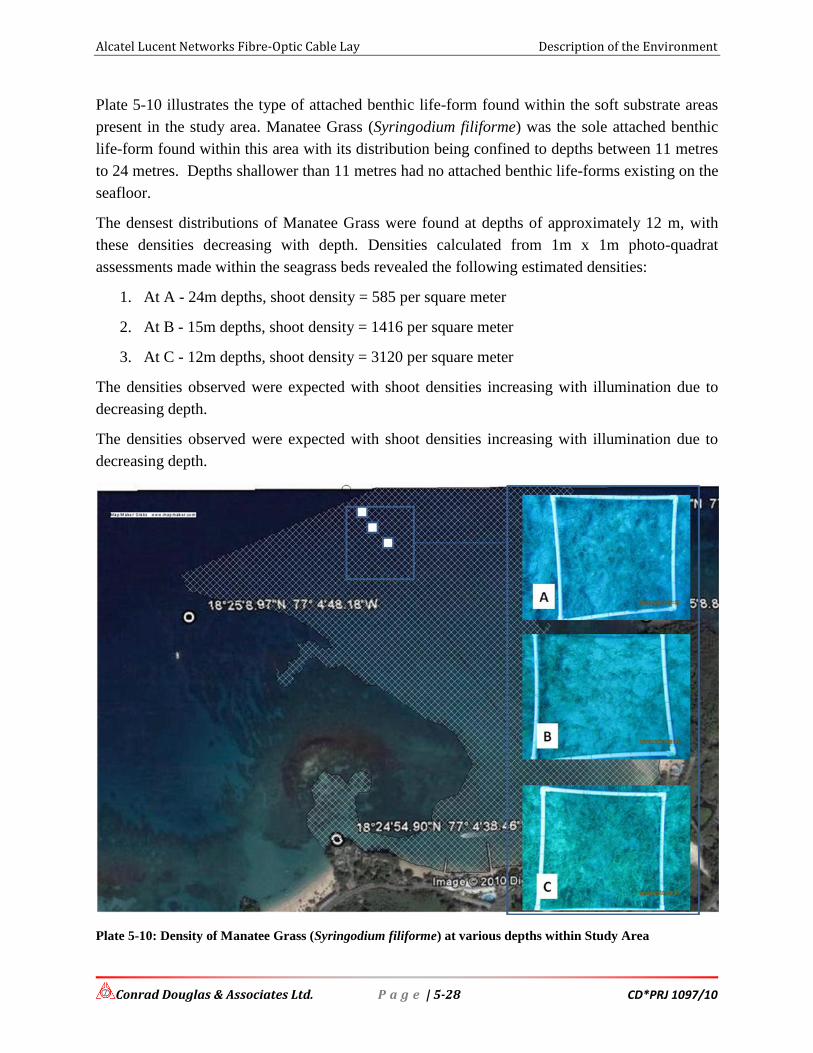
Alcatel Lucent Networks Fibre-Optic Cable Lay Description of the Environment
Conrad Douglas & Associates Ltd. P a g e | 5-28 CD*PRJ 1097/10
Plate 5-10 illustrates the type of attached benthic life-form found within the soft substrate areas
present in the study area. Manatee Grass (Syringodium filiforme) was the sole attached benthic
life-form found within this area with its distribution being confined to depths between 11 metres
to 24 metres. Depths shallower than 11 metres had no attached benthic life-forms existing on the
seafloor.
The densest distributions of Manatee Grass were found at depths of approximately 12 m, with
these densities decreasing with depth. Densities calculated from 1m x 1m photo-quadrat
assessments made within the seagrass beds revealed the following estimated densities:
1. At A - 24m depths, shoot density = 585 per square meter
2. At B - 15m depths, shoot density = 1416 per square meter
3. At C - 12m depths, shoot density = 3120 per square meter
The densities observed were expected with shoot densities increasing with illumination due to
decreasing depth.
The densities observed were expected with shoot densities increasing with illumination due to
decreasing depth.
Plate 5-10: Density of Manatee Grass (Syringodium filiforme) at various depths within Study Area

Alcatel Lucent Networks Fibre-Optic Cable Lay Description of the Environment
Conrad Douglas & Associates Ltd. P a g e | 5-29 CD*PRJ 1097/10
Plate 5-11: Close up of Seagrass densities in the study area

Alcatel Lucent Networks Fibre-Optic Cable Lay Description of the Environment
Conrad Douglas & Associates Ltd. P a g e | 5-30 CD*PRJ 1097/10
5.3.3.1.3 Mobile Life-form Spatial and Status Analysis:
The most prominent mobile life-forms observed on the reef areas peripheral to the project area
were marine reef fish. Plate 5-12 illustrates the types observed during the study period. No
obvious benthic mobile life-forms (including sea urchins, brittle stars and sea cucumbers) were
observed during the survey, with the exception of the Spiny Lobster (Panulirus argus).
Plate 5-12: Mobile Marine Life Observed Within Reef Areas Adjoining the Proposed Cable Route [Images
are internet photos]
It must be noted that the invasive Pacific Lionfish was observed on the reef within the study area
during the survey (Plate 5-13).

Alcatel Lucent Networks Fibre-Optic Cable Lay Description of the Environment
Conrad Douglas & Associates Ltd. P a g e | 5-31 CD*PRJ 1097/10
Plate 5-13: Lionfish Observed Within Reef Areas Adjoining the Proposed Cable Route
There was a scarcity of both mobile benthic and free-swimming life-forms observed on or over
the sandy substrates along the proposed cable route. Over the approximately 800 meters of
proposed alignment surveyed, one Ocean Trigger fish (Plate 5-14) of approximately 30cm in
length, one Stingray of approximately 30cm in diameter, and two schools of Ocean Surgeon Fish
juveniles numbering less than 20 individuals each were observed. The Surgeon Fish juveniles
were aggregated around two sunken logs on the seafloor. Several Sea Cucumbers and Starfish
(one genus of each - genus and species unidentified) were observed on the seafloor.

Alcatel Lucent Networks Fibre-Optic Cable Lay Description of the Environment
Conrad Douglas & Associates Ltd. P a g e | 5-32 CD*PRJ 1097/10
Plate 5-14: Examples of Mobile Marine Organisms Found Along Proposed Cable Alignment
5.3.3.2 Water Quality
Table 5-2 outlines the water quality trends for three water quality parameters identified for
investigation. Turbidity within the bay was relatively low except for near the shore and this is
seen in the clear images taken of benthic and mobile organisms. The values seen at the nearshore
are possible due to in water activities by boats and humans that were using the area. It should be
noted that the area is generally very clear.
The high dissolved oxygen represented near the shore is possible due in part to the surf zone near
the shore as well as the mixing of freshwater and seawater due to the White River emptying in
close proximity. pH values were consistent throughout. These values do not represent any cause
for alarm; neither will the project result in a worsening of these conditions in the long-term.
Turbidity is the only factor likely to be affected by project activities and this will be addressed
through the mitigation options outlined in this report.
Plate 5-15 represents the locations from which water samples were collected subsurface by
divers conducting the marine survey.

Alcatel Lucent Networks Fibre-Optic Cable Lay Description of the Environment
Conrad Douglas & Associates Ltd. P a g e | 5-33 CD*PRJ 1097/10
Table 5-2: Water Quality Parameters Tested
POSITION Water Quality Parameters
Turbidity [NTU] Dissolved Oxygen [mg/L] pH Depth [m]
18° 24' 56.02"N 77° 04' 21.63"W
6.3 8.4 8 <2
18° 25' 04.88N 77° 04' 28.97W
1.3 2.5 8.4 11
18° 25' 15.91"N 77° 04' 34.70"W
1.1 1.7 8.3 15
Plate 5-15: Subsurface Sample Locations for Water Samples Taken
5.3.3.3 Oceanography
Plate 5-16 illustrates the path of water movement, symbolized by wave movement, as influenced
by prevailing winds, which on the Google Image were originating from an easterly direction –
similar to the forecast predicted for Ocho Rios during the time of the assessment works.
Offshore, the general movement of seawater, as influenced by wind, is towards the west. As
proximity to shallower areas nearshore is reached, a process called refraction occurs; this
ultimately turns the moving water body towards the shoreline.

Alcatel Lucent Networks Fibre-Optic Cable Lay Description of the Environment
Conrad Douglas & Associates Ltd. P a g e | 5-34 CD*PRJ 1097/10
Wind primarily exerts its influence on the upper portions of the water column, thus the water
movements illustrated in Plate 5-16 can be described as surface water movements.
Diver-facilitated observation of subsurface water movements suggested an outward movement of
water from the bay, as illustrated in Plate 5-17. This would make sense, considering that if water
moves into a confined space, it has to evacuate that space at some point in time. It appears that
wind-influenced water movement occurs into the bay at the surface, with the inbound water
evacuating the bay by subsurface means.
Plate 5-16: Surface Water Movement as Influenced by Prevailing Easterly Winds (A) Orientation of Wave
Crests (B) Direction of Wave Movement.

Alcatel Lucent Networks Fibre-Optic Cable Lay Description of the Environment
Conrad Douglas & Associates Ltd. P a g e | 5-35 CD*PRJ 1097/10
Plate 5-17: Diver-deduced Sub Surface Water Movement within the Study Area (A) Approximate Subsurface
water movement direction.
Aerial Imagery assessments of June 2002 Google Earth images suggested that a plume of surface
bound fresh water discharged from the White River exited the Bay from its eastern extent, as
illustrated in Plate 5-18. The path of the plume was defined by the extent of turbid water
interpreted as exiting the mouth of the River. It is anticipated that a localized current movement
would be established at this location, where the fresh water would flow out of the bay under the
influence of its discharge force from the river mouth. Being less dense than seawater, the fresh
water would float on top of the seawater body. A reversal of water movement would occur in
the denser seawater, which would flow towards the river mouth to occupy the space vacated by
the fresh water.

Alcatel Lucent Networks Fibre-Optic Cable Lay Description of the Environment
Conrad Douglas & Associates Ltd. P a g e | 5-36 CD*PRJ 1097/10
Plate 5-18: Location of Potential Density Driven Currents Driven by Fresh Water Discharge from the Fresh
River (A).
5.3.3.4 Assessment – alternative route approaches
Plate 5-19 and Plate 5-20 outline possible locations for alternative approaches for the proposed
cable. These areas were identified within an area of shoreline bounded by the town of Ocho
Rios to the west and the Rio Nuevo bay to the east. The sites illustrated have been suggested
based solely on the presence of gaps in prevailing reef systems protecting the shoreline, through
which a cable could be routed and also on the presence of favourable sandy substrates on which
a cable could be safely laid without incurring any significant environmental damage. Note that
no consideration has been given to land ownership matters that may or may not make an
area feasible for landing.

Alcatel Lucent Networks Fibre-Optic Cable Lay Description of the Environment
Conrad Douglas & Associates Ltd. P a g e | 5-37 CD*PRJ 1097/10
Plate 5-19: Potential Landing Sites in close proximity to Proposed Site at (A) Sandals Ocho Rios [18° 24.846'N
77° 5.126'W] and (B) [18° 25.177'N 77° 3.366'W]
Plate 5-20: Potential Landing Sites (further East) at (A) Tower Isle along alignment of Existing Flow Cable
[18° 25.363'N 77° 2.421'W ] and (B) Rio Nuevo Bay [18° 24.632'N 77° 0.718'W]

Alcatel Lucent Networks Fibre-Optic Cable Lay Description of the Environment
Conrad Douglas & Associates Ltd. P a g e | 5-38 CD*PRJ 1097/10
5.3.4 Conclusions
The proposed route is ideal for the purposes at hand. It served the purposes of a Cable and
Wireless cable, the alignment of which was approved by NEPA (then NRCA) in the late 1990s.
The underlying seafloor substrates are benign in their character and, environmentally speaking,
should represent no issues where impacts are concerned provided that the proposed alignment is
maintained. Additionally, it is recommended that the cable simply be laid on the seafloor, with
no trenching being done. Natural sediment movement processes will ultimately cover the cable,
as was the case with the Cable and Wireless cable operation.
There are patches of coral reefs existing near the island drop off, at depths between 33-40 meters.
The proposed cable alignment will not impact on the coral reefs identified.

Alcatel Lucent Networks Fibre-Optic Cable Lay Socio-Economic & Socio-Cultural Environment
Conrad Douglas & Associates Ltd. CD*PRJ 1097/10
SOCIO-ECONOMIC & SOCIO-CULTURAL
ENVIRONMENT

Alcatel Lucent Networks Fibre-Optic Cable Lay Socio-Economic & Socio-Cultural Environment
Conrad Douglas & Associates Ltd. P a g e | 6-1 CD*PRJ 1097/10
6 Socio-Cultural & Socio-Economic Environment
6.1 Introduction
The region of St. Ann in which the project falls is a small residential community with a small
tourist destination. There are a few beaches in the area but most are on privately owned lands.
The commercial aspect of the area is also limited to small entrepreneurs and a few plazas. The
major economic hub, Ocho Rios is a mere 5-10 min drive to the west.
6.2 Cultural Heritage Resources
The parish of St. Ann has various cultural heritage sites scattered throughout, some protected.
However, there is no cultural heritage resource located within the immediate geographic sphere
of influence of this project.
The project proponents recognize the significance and importance of any cultural and
archaeological resources and are willing to cease operations should any of these resources be
discovered during the duration of project activities. All necessary protocol will be followed such
as informing the Jamaica National Heritage Trust (JNHT) and NEPA about these findings
immediately.
6.3 Land-Use
6.3.1 Approach & Method
Land use was examined from both a historical and regional perspective. Site specific analysis of
the proposed landing site and for areas within 1 km of the site was seen as an appropriate extent
for the area of interest. Relevant land uses immediately adjacent to the outer limits of the
selected buffer was also taken into account. The following were also useful in the investigation:
1. Aerial Photographs,
2. Satellite Imagery of the area dating 2006 (Google Earth), and
3. The use of field surveys to incorporate regional observations and documentation of
existing land use, while providing verification of land use patterns depicted on the maps.
An accurate and thorough account of past and current land uses in the study area demanded a
multi-faceted approach for collating land use information for the area.
6.3.2 Present Land Use
The site for the proposed cable lay comprises the nearshore and offshore waters and beach of a
private property (Golden Sands Beach Cottages) located at the mouth of the White River in
Shaw Park, St. Ann. The property comprises approximately two acres of beachfront lands at the
eastern border of the parish of St. Ann. The title is registered under the registration of tiles law of
1888.

Alcatel Lucent Networks Fibre-Optic Cable Lay Socio-Economic & Socio-Cultural Environment
Conrad Douglas & Associates Ltd. P a g e | 6-2 CD*PRJ 1097/10
The beach can be utilised by residents of the area up to the high tide mark (Crown lands). The
property is lands approximately just south of the Martha Brae exit of the North Coast Highway.
The property is bordered by private properties in all directions. Along the private roadway
leading to the North-Coast Highway to the south are hotels, guest houses and private residences.
At the entrance to the private road on the highway a small commercial plaza is situated. Situated
to the east and west are large hotels such as Couples San Souci (to the east) and Sandals (to the
west). The landing site has been used as a hotel and beach resort for more than 30 years and has
been in private hands for much longer. Large tracts of lands in this region are privately owned.
The North Coast Highway is a fairly recently redeveloped roadway stretching from Port Antonio
in the East to Negril in the west. The general area is primarily residential and commercial (tourist
interest). The major hub in close proximity is Ocho Rios to the west.
Plate 6-1 below outlines the survey diagram attached to the certificate of title as well as
photographs showing various aspects of the general area.

Alcatel Lucent Networks Fibre-Optic Cable Lay Socio-Economic & Socio-Cultural Environment
Conrad Douglas & Associates Ltd. P a g e | 6-3 CD*PRJ 1097/10
Plate 6-1: Characteristics of surrounding areas

Alcatel Lucent Networks Fibre-Optic Cable Lay Socio-Economic & Socio-Cultural Environment
Conrad Douglas & Associates Ltd. P a g e | 6-4 CD*PRJ 1097/10
6.3.3 Potential Land Use Conflicts
Potential land use conflicts are few. They can be grouped as follows:
1. Conflicts with transportation corridor (land and sea)
2. Conflicts with existing telecommunications services (land and sea)
3. Conflicts with owners of landing area
4. Conflict with marine interests (fishermen, private boaters, users of the beach among
others)
6.3.3.1 Conflicts with transportation corridor (land and sea)
As discussed previously in this report, there is limited potential conflict with road and sea going
vessels. During the process of physical site surveying as well as the proposed landing of the
cable, all relevant parties will be informed of the dates of installation to ensure no incidences of
note occurs.
The communication program will include the Maritime Authority of Jamaica, Port Authority of
Jamaica and Fisheries Department as well as direct communication with fishermen from the
White River Area, the owners of the Golden Sands Beach Cottages as well as all hotels, guest
houses and private residences within a 1 km radius of the landing site.
6.3.3.2 Conflicts with existing telecommunications services (land and sea)
A fibre-optic cable was landed at this site in 1997 by Cable & Wireless. This proposed landing
will utilise LIME Jamaica, a subsidiary of the Cable & Wireless, as the cable operators in
Jamaica, and as such they have already been informed and are a part of the proposed landing.
Every effort has been and will continue to be maintained to ensure the existing cable is not
damaged in any way.
LIME will undertake the responsibility of the cable once it has been established in the beach
manhole. It is the responsibility of LIME to undergo any trenching along the road corridor to
Ocho Rios. They have a memorandum of understanding with the NWA and the local parish
council with regards to a right-of-way agreement for any works along road corridors in the area.
This agreement is replicated through-out the entire country. The necessary arrangements such as
warning signs, traffic management approaches (news bulletins, traffic wardens, signal lights etc)
will be put in place as necessary by LIME.
6.3.3.3 Conflicts with owners of landing area
No conflicts are expected with the owners of the landing site. A lease agreement and
memorandum of understanding is in place with the property owners.

Alcatel Lucent Networks Fibre-Optic Cable Lay Socio-Economic & Socio-Cultural Environment
Conrad Douglas & Associates Ltd. P a g e | 6-5 CD*PRJ 1097/10
6.3.3.4 Conflict with marine interests (fishermen, private boaters, users of the beach among others)
No conflicts are expected with marine interest in the area. The property owner will be kept
informed of progress before, during and after the cable has been landed. Similarly, all fishing
interest will be kept informed of the intentions of the project team as it relates to intended dates
for cable laying in Jamaica’s maritime space. Private interests in the area and users such as
fishermen, boaters and bathers will be informed through all possible direct means such as
meetings, news bulletin, flyers etc.
6.4 Synopsis of Focus Group Consultations
In keeping with the approach to get feedback from the community, additional stakeholders were
identified and interviewed. Due to the nature of the project the stakeholders surveyed were users
of the marine environment in the general White River area. Their perceptions, views and
concerns are considered vital and are therefore a critical component to be included in this socio-
economic assessment. A copy of the survey instrument can be found in the appendix (Appendix
III).
A total of nineteen (19) persons were interviewed all being fishermen by trade. Only two (2) had
other livelihoods being rafter and painter. Seven (7) were self employed with the remainder
employing between 2 and 4 other individuals. Seventeen (17) are fishermen for more than 10
years with four (4) doing so for more than 40 years. Only 2 individuals have been fishing for less
than 5 years.
The majority of respondents considered the communities of the area to be either safe or very
safe. Services offered by telecommunications (telephone, cable and internet) were considered to
be adequate by the majority (17); however, some individuals had reservations for internet access
(4), cable television (4) and telephone (2).
Most of the respondents (13) were aware of the proposed cable lay. This may be attributed to
discussions held with some users (mainly fishermen) during site inspection activities as well as a
meeting convened at the landing site for fishing interest of the area in March 2010. Additionally,
the Fisheries Department were consulted and informed on the proposed cable lay.
The possible impact on their livelihood was considered nil by most respondents. Thirteen (13)
indicated they expected no change to their livelihood as a result of the project, 3 had no opinions
and 6 indicated a potential positive impact. This was largely realised by a few individuals
indicating they expected jobs as a result of this project. Most respondents were aware of the
previous cable lay in 1997 by Cable & Wireless and indicated it has caused no problem for users
of the beach of its nearshore and offshore waters. Based on this information most (12) were able
to identify the proposed activity as being of little risk to their livelihood. Those that suggested
their may be a potential risk identified change in spawning grounds and fish migrating as their
primary concern.

Alcatel Lucent Networks Fibre-Optic Cable Lay Socio-Economic & Socio-Cultural Environment
Conrad Douglas & Associates Ltd. P a g e | 6-6 CD*PRJ 1097/10
Most respondents held the opinion that the proposed cable lay was a vital development needed in
Jamaica. They cited technological improvements, jobs, skills training, potential for more
business and better and improved communication as the main reasons. Other developments
slated for the area include: housing, hotel construction and the laying of new and/or upgraded
water mains.
The fishing grounds used are mainly within the nearshore and offshore waters of Shaw Park.
However, some fishermen ventured to other parishes and deep sea to improve their fishing
efforts. Areas fished beyond the Shaw Park/Ocho Rios area included Montego Bay, sections of
Trelawny, St. Ann, St. Mary and Portland, all found along the northcoast.
The primary methods of fishing practiced in the area are: hook and line (15), traps/pots (13) and
spearfishing (7). However, it should be noted that some deep sea trawling is practiced, this
accounted for 8 responses including the above mentioned practices. Most fishing was done in the
early morning (18). However, it should be noted that fishing was practiced at other times during
the day such as: mid-day (3), evenings (2) and nights (3).
6.5 General Survey Population
6.5.1 Demographics & Social Profile
The opinions, attitudes and views of the communities within which this project is proposed to be
conducted must be taken into consideration despite the seemingly innocuous nature of the
proposed works. In an attempt to comprehensively analyze the potential impacts associated with
the proposed fibre optic cable lay a social impact assessment is necessary to obtain data on the
demographic and other social characteristics of the communities and residents within a
reasonable sphere of influence, and most importantly, their knowledge, views and concerns
regarding the proposed actions. This section of the report presents the demographic and other
social characteristics of the region. This survey was conducted in June 2010.
A 1.6 kilometre (1 mile) radius was identified as the sphere of influence for the proposed fibre
optic cable lay. However, given the nature of the proposed project and the dispersed locations of
communities in the area, a few communities were excluded from the sample. Communities
surveyed include:
Table 6-1: List of communities surveyed
Enumeration Districts Communities
NorthEast 48
1. Content Gardens/Bypass 2. Pineapple Place 3. DaCosta Drive 4. James Avenue

Alcatel Lucent Networks Fibre-Optic Cable Lay Socio-Economic & Socio-Cultural Environment
Conrad Douglas & Associates Ltd. P a g e | 6-7 CD*PRJ 1097/10
Enumeration Districts Communities
NorthEast 52
1. Content Gardens 2. NE54 3. Shaw Park 4. Content Gardens/Bypass 5. Great Pond 6. Eltham/Great Pond 7. Great Pond/Power Isle 8. Shaw Park/River Oak 9. Great Pond/Exchange Top 10. Exchange Top 11. Pineapple/Bypass 12. Pineapple Place 13. Top Hill Street
NorthEast 53 1. Content Garden 2. Ocho Rios Bypass 3. Marvin Park
NorthEast 55
1. Dunnsville 2. Eltham 3. Dunnsville/Cornhouse 4. Marvin Park
NorthEast 57 1. White River: Milford 2. Exchange 3. Buckfield
NorthEast 58
1. White River 2. Hand to Mouth 3. Middle Street 4. Prosper Hall
West 01
1. White River 2. Eastern Prospect Property 3. White River/Dunnsville 4. Gayle Road
The selection of the areas for interviewing was based on Enumeration Districts (ED) as defined
by the Statistical Institute of Jamaica (STATIN). However, it must be noted that it is possible for
some communities to cross ED boundaries. As a result, the communities as presented in this
report were also defined in the field by the interviewer and the respondent.
The survey population was devised from a 5% sample of the total number of households within
the area according to the 2001 Population Census. A total of 73 surveys were conducted in the
EDs as outlined by STATIN, which were within and/or along the periphery of the 1.5 km radius
of influence (Table 6-2 and Plate 6-2).
Table 6-2: Enumeration Districts Surveyed
Parish and Enumeration District
Population Number of Households Sample Population (5%)
NORTHEAST 48 179 118 6
NORTHEAST 52 360 107 5

Alcatel Lucent Networks Fibre-Optic Cable Lay Socio-Economic & Socio-Cultural Environment
Conrad Douglas & Associates Ltd. P a g e | 6-8 CD*PRJ 1097/10
Parish and Enumeration District
Population Number of Households Sample Population (5%)
NORTHEAST 53 356 227 11
NORTHEAST 54 475 233 12
NORTHEAST 55 455 263 13
NORTHEAST 57 146 84 4
NORTHEAST 58 599 353 18
WEST 01 88 75 4
TOTAL 2658 1460 73
Plate 6-2: 1.5 km radius for Socio-Economic Assessment
Communities identified within the sphere of influence together have a total population of 2658
individuals and 1460 households. The age-sex pyramid indicates that the majority of the
respondents (39.7%) are between the ages of 20 and 39 years, while individuals under the age of
20 years and those over the age of 60 years accounted for the smallest (12% and 11%
respectively) (Figure 6-1). Of the 73 households interviewed, the ratio of male to female
respondents was approximately 2:1 in favour of males. Forty-five (45) males and twenty-eight
(28) females were interviewed.

Alcatel Lucent Networks Fibre-Optic Cable Lay Socio-Economic & Socio-Cultural Environment
Conrad Douglas & Associates Ltd. P a g e | 6-9 CD*PRJ 1097/10
Age-Sex Pyramid for Respondents
25 20 15 10 5 0 5 10 15 20 25
<20 yrs.
20-39 yrs.
40-49 yrs.
50-59 yrs.
60+ yrs
Age
Gro
up
Percent
Males(%) Females(%)
Figure 6-1: Age-Sex Pyramid of Respondent Population
At least 80% of householders have been living in the area for more than 10 years, and at least
56% for more than 20 years. The number of individuals that occupied these households was 321
with a ratio of 1:1 for males to females. With respect to the age range of householder; the three
most dominant groups are 0-14 years (90), 20-35 years (74) and 36-45 years (54). There are 156
individuals with paid employment and this represent approximately 49% of householders.
Seventy-nine percent (79%) of respondents are in paid employment.
Secondary education is the most common education attained with 51% of the respondents (39
individuals). Only ten respondents (13%) have achieved tertiary level education and five
individuals have vocational training.

Alcatel Lucent Networks Fibre-Optic Cable Lay Socio-Economic & Socio-Cultural Environment
Conrad Douglas & Associates Ltd. P a g e | 6-10 CD*PRJ 1097/10
Table 6-3: Age and Sex of Residency of Respondents
Community ►
No
rth
-Eas
t
48
No
rth
-
East
52
No
rth
-
East
53
No
rth
-
East
54
No
rth
-
East
55
No
rth
-
East
57
No
rth
-
East
58
Wes
t 0
1
TOTA
L
Parameter ▼
AGE RANGE
Under 20 1 0 0 0 3 0 0 1 5
20-39 1 2 1 1 4 2 3 0 14
40-49 4 1 7 8 4 1 5 2 32
50-59 0 0 1 1 3 1 6 2 14
60-Over 0 0 1 3 1 0 3 0 8
NR 0 0 2 0 1 0 0 0 3
Total 6 3 12 13 16 4 17 5 76
YEARS OF RESIDENCY
0-5 Yrs 1 0 0 2 4 1 0 1 9
6-10 Yrs 0 1 0 0 0 0 1 0 2
11-20 Yrs 1 2 3 4 5 0 2 3 20
20+ Yrs 3 0 9 7 5 3 14 0 41
No Response 1 0 0 0 2 0 0 1 4
Total 6 3 12 13 16 4 17 5 76
A wide range of occupation was provided by respondents. The most dominant being self
employed (20), businessperson (11) and fishermen (10). The following list outlines the range of
occupation enjoyed by respondents.
Figure 6-2: Range of Occupation enjoyed by Respondents

Alcatel Lucent Networks Fibre-Optic Cable Lay Socio-Economic & Socio-Cultural Environment
Conrad Douglas & Associates Ltd. P a g e | 6-11 CD*PRJ 1097/10
6.5.2 Findings
6.5.2.1 Knowledge and Views on the Proposed Fibre-Optic Cable Lay
Awareness of the proposed project was fairly high with approximately 60% of respondents
stating they were aware of the proposed cable lay. There were no dissenting opinions on the
proposed project; however, at least 5 individuals had no view or no comment of its favourability.
Of those stating they were in favour of the project 62% were in favour and 16% strongly in
favour (Figure 6-3).
Favourable views on proposed project
16%
62%
14%
0%
3%
5%0%
Strongly in favour
In favour
Neither in favour or against
Against
Strongly against
Don't Know
NR
Figure 6-3: Bar Chart showing major source of water in the areas surveyed
The primary reason given for the favourable responses was the potential improvement in
technology / communication services and lower cost through increased competition. This reason
accounted for approximately 42% of all reasons provided (Figure 6-4).
Other notable reasons included: it’s good for the community, better service rate and potential for
employment.

Alcatel Lucent Networks Fibre-Optic Cable Lay Socio-Economic & Socio-Cultural Environment
Conrad Douglas & Associates Ltd. P a g e | 6-12 CD*PRJ 1097/10
Reasons given for Views on the Proposed Cable Landing
8%
13%
3%
5%
3%
6%
6%
3%
2%
2%
2%
5%
42%
Not Sure
good for the community
Help in education in school & work
Improved technology/communicationsservices/more competition
Globalisation
Adverse impact on environment
NR
Better service rate
Safety
Investment opportunities
Positive impact
No Impact
employment opportunities
Figure 6-4: Reasons for favourable responses to the proposed project
Respondents were largely of the view that the installation of the proposed cable would have a
positive economic value to the community. This positive view was shared by 78% of
respondents. Potential employment as a result of the proposed project was expected from 74% of
respondents. The potential for pollution was not regarded as high.
Services provided by fibre optic cables such as telephone, internet and cable television were
considered to be adequate in the area (Figure 6-5). Of the three, only internet (32%) registered
any significant negative response, positive response for this service was higher almost on a ration
of 2:1.
Thirty-seven percent of respondents were aware of the previous cable that was laid at the Shaw
Park Beach; at least 60% were unaware. Most respondents (75%) were of the view that the cable
landing would have no impact on them personally. More than ninety percent of respondents were
of the view that the proposed cable lay was a required development. Improved internet and
communication services, community advancement and potential employment are considered as
the main potential development impacts on the community should the project go ahead.

Alcatel Lucent Networks Fibre-Optic Cable Lay Socio-Economic & Socio-Cultural Environment
Conrad Douglas & Associates Ltd. P a g e | 6-13 CD*PRJ 1097/10
Adequacy of Services provided by Fibre-Optic Cables
0
10
20
30
40
50
60
70
80
Internet Telephone Cable tv
Category
Nu
mb
er
of
Re
spo
nd
en
ts
Yes
No
Don't Know
NR
Figure 6-5: Adequacy of services provided by fibre optic cable
6.5.2.2 Social Attitudes
Less than seven percent of respondents have worked in the telecommunications industry.
However, more than 86% are looking forward to the development with the outcome expected to
be similar as the opinions already expressed.
Based on this outlook the majority of respondents do not foresee this proposed project impacting
negatively on the resources in the area they currently enjoy. More than 71% of respondents do
not anticipate that the fibre-optic cable lay and any associated construction activities will affect
the availability of any of the natural resources in the area. Those that had a dissenting view
identified fishing and use of beach as the resources that may be impacted.
The Golden Sands Beach and its environs are primarily used for swimming, recreation and
fishing. Approximately 60% of those surveyed listed swimming as the primary use of the natural
resources. At least 62% were of the view the proposed cable lay would not negatively impact on
the environment.
6.6 Conclusions
The survey covered several communities and total of 76 households, which accounts for 5% of
the total households in the area based on the STATIN 2001 National Census and the defined
sphere of influence of the proposed development of 1.6 km. Interviews were conducted with a
mature population with the age group 20 - 39 and 40 – 49 accounting for approximately 60% of
the respondents, who have mostly been living in the area for over a decade. Their opinions and

Alcatel Lucent Networks Fibre-Optic Cable Lay Socio-Economic & Socio-Cultural Environment
Conrad Douglas & Associates Ltd. P a g e | 6-14 CD*PRJ 1097/10
perception on current situations and prospective development are therefore considered critical
and important in understanding the social ramifications that may be associated with the proposed
fibre optic cable lay.
Generally speaking the respondents were largely in agreement with the proposed cable landing.
Most were aware of the project. The main positive impacts anticipated were improved
technology/communication services, improvements in community development through skills
training in IT, and potential employment.
Although the natural resources of the area are used for various activities, it was largely felt that
these activities would not be impacted by the proposed project. The focus group of marine users
were also positive about this proposed project. They are extremely pleased with the
communication to date. Most are of the view that their activities will not be impacted by the
proposed cable lay. At most fish and other marine life are expected to migrate during the cable
laying activities.
There are no natural or archaeological resource that may be impacted by the proposed cable lay.

Alcatel Lucent Networks Fibre-Optic Cable Lay Determination of Potential Impacts & Mitigation
Conrad Douglas & Associates Ltd. CD*PRJ 1097/10
DETERMINATION OF POTENTIAL IMPACTS &
MITIGATIONS

Alcatel Lucent Networks Fibre-Optic Cable Lay Determination of Potential Impacts & Mitigations
Conrad Douglas & Associates Ltd. P a g e | 7-1 CD*PRJ 1097/10
7 Determination of Potential Impacts
7.1 Introduction
The proposed fibre-optic cable landing site has the potential to create a variety of impacts if it is
implemented. These potential impacts can be either positive or negative depending on the
receptors involved and other parameters such as magnitude, duration, project management and
monitoring. Since this section of the report is geared primarily towards identification of potential
environmental impacts their definitions and significance are presented in greater detail in the
appendix, especially to assist the public review process (Appendix VI).
In assessing the significance of potential impacts, various measures are used. These include the
use of checklists/matrices, expert knowledge and a keen assessment of the project plans and
details. Each parameter is evaluated according to the following:
Potential impact - any change to the environment, whether adverse or beneficial, wholly
or partially resulting from the proposed activities, products or services
Activity – phase of development that action takes place in
Environmental receptor – sensitive component of the ecosystem that reacts to or is
influenced by environmental stressors
Magnitude – A measure of how adverse or beneficial an effect may be
Duration – the length of time needed to complete an activity
Significance – A measure of importance of an effect
Mitigation – Measures taken to reduce adverse impacts on the environment
Outlined below are the various phases of the proposed development on which assessments of
potential impacts will be based, namely:
Physical environment
Biological environment
Socio-economic environment
Mitigation measures are provided, where necessary, within the impact identification tables.
7.2 Impact Identification & Mitigation
This project is not expected to provide any significant employment opportunities during the
cable lay. However, the value added service of an additional fibre optic cable in Jamaica will
undoubtedly provide employment opportunities in various sectors such as telecommunications,
conference facilities among others. During the cable lay it is possible that marine interest in the

Alcatel Lucent Networks Fibre-Optic Cable Lay Determination of Potential Impacts & Mitigations
Conrad Douglas & Associates Ltd. P a g e | 7-2 CD*PRJ 1097/10
area (boatmen and divers) may be required to successfully deploy the cable, due to their
proximity to the project site and their knowledge of the area and operations there.
The Island should see increased revenues from Income, Royalties and General Consumption
Taxes related to the installation of the cable. Similarly, the local economy of the area will benefit
from increases in good and services as a result of the increased telecommunications framework
to be provided. This is a significant positive, both direct and indirect, long-term impact on the
economy of Jamaica.
The potential environmental impacts identified as a result of the proposed cable lay includes:
Negative
Minimal suspended solids during cable laying
Minimal noise and vibration during cable lay and trench construction
Minimal aesthetics and transient change of land and marine use
Positive
Improved broadband access by connection to other islands and continents
Potential vast increase in investment revenue and job creation due to improvements in the
telecommunications industry from this project.
No loss of biodiversity
No loss of archaeological and historical heritage resources
No loss of aesthetic appeal
No loss of commercial and recreational fishing needs.
The following tables provide a clear indication of real and potential environmental impacts
associated with this development, and provide information on potential receptors, duration,
magnitude, and mitigation measures. Since these are potential impacts, there is no certainty that
they will materialize. However, the developers will be prepared to address any adverse potential
impacts should they arise during this cable laying project.
Mitigation costs associated with this project have been incorporated into the overall
development cost and are not detailed in the mitigation assessment.
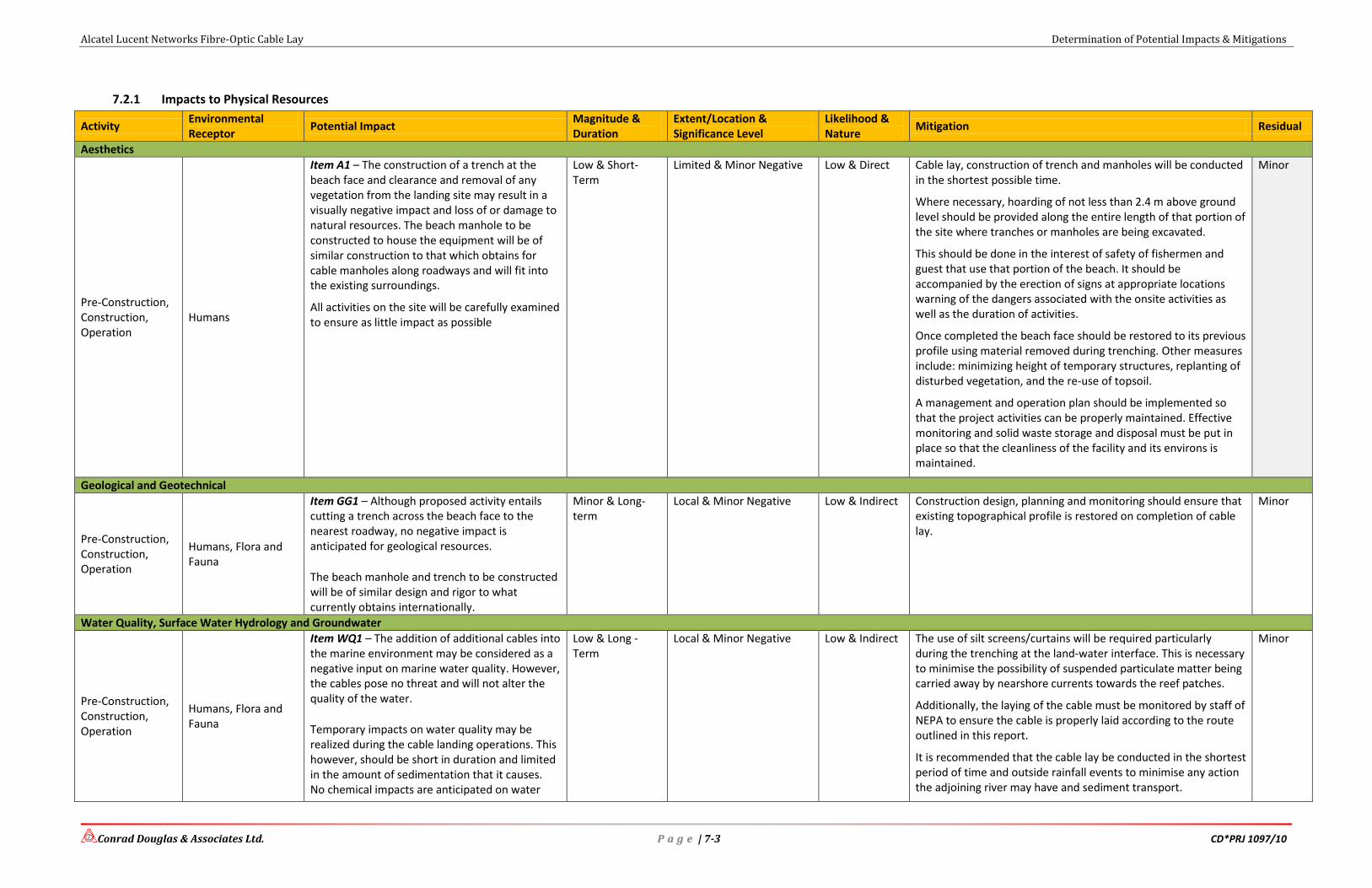
Alcatel Lucent Networks Fibre-Optic Cable Lay Determination of Potential Impacts & Mitigations
Conrad Douglas & Associates Ltd. P a g e | 7-3 CD*PRJ 1097/10
7.2.1 Impacts to Physical Resources
Activity Environmental Receptor
Potential Impact Magnitude & Duration
Extent/Location & Significance Level
Likelihood & Nature
Mitigation Residual
Aesthetics
Pre-Construction, Construction, Operation
Humans
Item A1 – The construction of a trench at the beach face and clearance and removal of any vegetation from the landing site may result in a visually negative impact and loss of or damage to natural resources. The beach manhole to be constructed to house the equipment will be of similar construction to that which obtains for cable manholes along roadways and will fit into the existing surroundings.
All activities on the site will be carefully examined to ensure as little impact as possible
Low & Short-Term
Limited & Minor Negative Low & Direct Cable lay, construction of trench and manholes will be conducted in the shortest possible time.
Where necessary, hoarding of not less than 2.4 m above ground level should be provided along the entire length of that portion of the site where tranches or manholes are being excavated.
This should be done in the interest of safety of fishermen and guest that use that portion of the beach. It should be accompanied by the erection of signs at appropriate locations warning of the dangers associated with the onsite activities as well as the duration of activities.
Once completed the beach face should be restored to its previous profile using material removed during trenching. Other measures include: minimizing height of temporary structures, replanting of disturbed vegetation, and the re-use of topsoil.
A management and operation plan should be implemented so that the project activities can be properly maintained. Effective monitoring and solid waste storage and disposal must be put in place so that the cleanliness of the facility and its environs is maintained.
Minor
Geological and Geotechnical
Pre-Construction, Construction, Operation
Humans, Flora and Fauna
Item GG1 – Although proposed activity entails cutting a trench across the beach face to the nearest roadway, no negative impact is anticipated for geological resources.
The beach manhole and trench to be constructed will be of similar design and rigor to what currently obtains internationally.
Minor & Long-term
Local & Minor Negative Low & Indirect Construction design, planning and monitoring should ensure that existing topographical profile is restored on completion of cable lay.
Minor
Water Quality, Surface Water Hydrology and Groundwater
Pre-Construction, Construction, Operation
Humans, Flora and Fauna
Item WQ1 – The addition of additional cables into the marine environment may be considered as a negative input on marine water quality. However, the cables pose no threat and will not alter the quality of the water.
Temporary impacts on water quality may be realized during the cable landing operations. This however, should be short in duration and limited in the amount of sedimentation that it causes. No chemical impacts are anticipated on water
Low & Long -Term
Local & Minor Negative Low & Indirect The use of silt screens/curtains will be required particularly during the trenching at the land-water interface. This is necessary to minimise the possibility of suspended particulate matter being carried away by nearshore currents towards the reef patches.
Additionally, the laying of the cable must be monitored by staff of NEPA to ensure the cable is properly laid according to the route outlined in this report.
It is recommended that the cable lay be conducted in the shortest period of time and outside rainfall events to minimise any action the adjoining river may have and sediment transport.
Minor

Alcatel Lucent Networks Fibre-Optic Cable Lay Determination of Potential Impacts & Mitigations
Conrad Douglas & Associates Ltd. P a g e | 7-4 CD*PRJ 1097/10
Activity Environmental Receptor
Potential Impact Magnitude & Duration
Extent/Location & Significance Level
Likelihood & Nature
Mitigation Residual
quality. All trenches constructed should be filled in at the earliest possible opportunity and the beach returned to its pre-activity state.
The timely removal of removed and/or stockpiled soils and the use of containment berms, bunds or containers to secure soils and avoid siltation, etc. during incidence of rainfall are recommended.
Air Quality
Pre-Construction, Construction, Operation
Humans, Flora and Fauna
Item AQ1 – It is possible that a small amount of fugitive dust may be produced during manhole construction at the proposed landing site.
Trenching along the roadway also has the potential for observable fugitive dust. Otherwise, this project should not result in any negative air quality events as it relates to fugitive dust.
Low & Short -Term
Local & Minor Negative Low & Indirect Although the removed material may be of small volume it is recommended that the excavated soil and exposed soil surfaces be sprinkled as necessary and not allowed to dry out enough to become entrained in wind.
Stockpile material for disposal elsewhere that may generate fugitive dust should be totally covered during transportation. Proper personal protection equipment (PPE) devices such as face mask should be provided to workers as necessary.
Minor
Item AQ2 – Various mechanical equipment and vehicles are expected to be used at the project site. The heavy duty vehicles are expected to be primarily diesel fuel vehicles. When properly maintained heavy duty vehicles can operate without causing a significant decrease in air quality. However, if maintenance is poor, excessive fugitive emissions may result.
Low & Short-Term
Local & Minor Negative Low & Indirect Heavy duty equipment and vehicles using diesel fuel should be properly maintained and inspected prior to use at the site.
All vehicular and equipment maintenance should be done at an approved off-site maintenance location such as a garage or dry dock. Vehicles causing excessive fugitive emissions should be removed from the site immediately.
Minor
Noise
Pre-Construction, Construction, Operation
Humans and Fauna
Item N1 – Various mechanical equipment, vehicles and site activities may generate noise that may exceed acceptable levels.
It is not expected that the project will cause a noise nuisance at any point, that is, neither during installation nor operation. Where necessary, work requiring heavy equipment will be scheduled for day-time and will be brief to minimize the potential for disruption of residents and guests. Operation will not produce any noise.
Low & Short-Term
Local & Minor Negative Low & Direct Silencers or mufflers on equipment sand vehicles should be properly fitted and maintained. If proposed site activities are known to be noisy, they should be scheduled at times least likely to impact those in hearing distance such as users of the beach and hotel.
Proper personal protection equipment (PPE) devices such as ear plugs should be provided to workers as necessary.
Minor

Alcatel Lucent Networks Fibre-Optic Cable Lay Determination of Potential Impacts & Mitigations
Conrad Douglas & Associates Ltd. P a g e | 7-5 CD*PRJ 1097/10
7.2.2 Impacts to Biological Resources
Activity Environmental Receptor
Potential Impact Magnitude & Duration
Extent/Location & Significance Level
Likelihood & Nature
Mitigation Residual
Faunal Resources
Pre-Construction, Construction, Operation
Fauna
Item FaR1 – No large-scale land clearance is proposed for the landing site. The manhole to be constructed is not large and is mostly underground. Trenching from the beach to the road is not expected to significantly disturb the area.
Low & Short-Term Local & Minor Negative High & Direct There are no significant fauna that stand to be impacted by the proposed actions. No mitigation necessary
Minor
Item FaR2 – The laying of the cable in the marine environment may impact on sessile marine fauna.
It is in the best interest of those laying the cables to avoid corals or other structures in order to protect the cable. The cable is to be laid completely flat on the sea floor.
Low & Long-Term Local & Minor Negative High & Direct The cable lay in the marine environment up to the high water mark must be done as outlined in the route identified in this report.
NEPA officers should be present during the cable lay to ensure the cable does not impact on sensitive marine resources such as coral reefs. Where necessary, the cable should be anchored. Sessile organisms such as sponges and molluscs are known to establish themselves on marine cables
Minor
Floral Resources
Pre-Construction, Construction, Operation
Flora
Item FlR1 – The laying of the cable in the marine environment may impact on marine flora.
The cable will be laid through an area of sea grass and is unavoidable. The seagrass is found in patches. No significant thick meadows exist.
Low & Long Term Local & Major Negative High & Direct The laying of the cable on seagrass may inadvertently lead to a loss of seagrass in the immediate area. However, over time the cable is expected to bury itself in the substrate and allow for seagrass re-growth.
Seagrass is known to eventually grow to cover cables and the same is expected in this case. NEPA officers should be present during the cable lay to ensure the cable does not impact significantly on sensitive marine resources such as seagrass.
Minor

Alcatel Lucent Networks Fibre-Optic Cable Lay Determination of Potential Impacts & Mitigations
Conrad Douglas & Associates Ltd. P a g e | 7-6 CD*PRJ 1097/10
7.2.3 Impacts on Socio-Economic & Socio-Cultural Resources
Activity Environmental Receptor
Potential Impact Magnitude & Duration
Extent/Location & Significance Level
Likelihood & Nature
Mitigation Residual
Employment & Worker Health & Safety
Pre-Construction, Construction, Operation
Humans
Item E&HS1 – This project will provide employment opportunities during all phases of project implementation, which will include residents of the surrounding communities due to their proximity to the project site, and their knowledge of the area and operations there.
When fully implemented, i.e. the cable has been installed and the infrastructure has been prepared, the project may result in jobs being realized though increased telecommunication and other related industries on the island.
All the phases of the project implementation will generate local employment (some more than others) but the cumulative impact will be positive for the Jamaican economy.
Major & Long-Term
Regional & Major Positive High & Direct No mitigation required. Positive
Item E&HS2 –Occupational Safety Risks are associated with any working condition. This is primarily important where workers interact with moving and heavy equipment.
Low & Short-Term Limited & Minor Negative Low & Direct Proper PPE should be issued to workers depending on the area they work in. This should include boots, ear plugs, goggles, gloves and hard hats at a minimum, where necessary.
Positive
Item E&HS3 – Due to the services which can be received via installation of Fibre Optic cables, such as, faster remittance, faster transmission of data (sending and receiving), over broad band internet, better telecommunications, safer and less vulnerable international connections etc., there will be several positive impacts on the entire island. These include:
Remittances would be received more quickly; therefore there could be an increase in the remittances sent to the island. This would in turn mean an increase in revenue for the country.
Due to easier access to information (internet), the scope of knowledge of individuals would increase. Also, the less time spent obtaining this information, the more time would be left available for other activities.
Jamaica would become an example in the Caribbean of high quality international
Major & Long-Term
Regional & Major Positive High & Direct No mitigation required. Positive

Alcatel Lucent Networks Fibre-Optic Cable Lay Determination of Potential Impacts & Mitigations
Conrad Douglas & Associates Ltd. P a g e | 7-7 CD*PRJ 1097/10
Activity Environmental Receptor
Potential Impact Magnitude & Duration
Extent/Location & Significance Level
Likelihood & Nature
Mitigation Residual
telecommunications. Also, in inclement weather, the risk of service disruption would be very low. This ensures that productivity is not disrupted.
Cheaper communication service. With this decrease in cost, the service would be affordable to more people, improving the overall standard of living.
Recreation & Heritage Sites
Construction & Operation
Human
Item R&H1 – The proposed landing area can be considered a recreational area. It is utilised primarily by guests of the Golden Sands Beach Cottages and also by the White River fishermen.
No known heritage resources are known to occur at the proposed landing site that may be adversely impacted.
Minor & Short-Term
Regional & Minor Negative Low & Indirect Adequate and proper signs and barriers should be put in place warning and protecting everyone from the proposed activities associated with the fibre optic cable lay.
NEPA officers should be present during the cable lay to monitor the activities and ensure all mitigation measures are adhered to and the beach and marine environment are left in as good as or even better state than originally found.
Based on the nature of the previous and current site usage and the proposed project, it is not anticipated that archaeological heritage resources will be found.
Minor
Traffic
Pre-Construction, Construction, Operation
Humans
Item T1 – The existing main roads will be used to deliver and remove any materials, and equipment to and from the proposed landing site.
The added vehicles and the frequency of their movement are minimal and not expected to add to the existing volume on the main and private roads during peak usage periods.
Moderate & Short-term
Regional & Minor Negative Low & Direct No Mitigation necessary Minor
Solid Waste
Pre-Construction, Construction, Operation
Humans
Item SW1 – Solid waste generated during cable laying activities, trenching, manhole construction and other waste from packaging may be generated during this exercise.
If these waste streams are not properly managed then the potential exists for a negative impact. A properly implemented and executed solid waste management plan can remove this negative potential.
Low & Short-Term Limited & Minor Negative Low & Indirect All solid waste generated should be collected, handled and disposed of appropriately. Solid waste removal should be facilitated by using approved licensed haulage contractors.
A comprehensive project based waste management plan will be prepared for the duration of the exercise.
Minor

Alcatel Lucent Networks Fibre-Optic Cable Lay Determination of Potential Impacts
Conrad Douglas & Associates Ltd. P a g e | 7-8 CD*PRJ 1097/10
7.3 Cumulative Impacts Identification & Mitigation
7.3.1 Impacts to Physical Resources
The area already accommodates one (1) fibre optic cable that was laid in 1997. This cable has
had no adverse impact on the physical resources of the area. The cable has since buried itself and
is not visible anywhere within the nearshore waters.
It is not envisaged that the laying of the new cable will result in any adverse potential impacts to
these resources. No adverse cumulative impact is expected.
7.3.2 Impacts to Biological Resources
The biological resources of the area, primarily the seagrass meadows and coral reefs are in a
poor state. However, the marine assessment has revealed improving conditions within the area.
The existing fibre optic cable has not affected the existing biological resources in an adverse
manner.
It is not envisaged that the laying of the new cable will result in any adverse potential impacts to
these resources. No adverse cumulative impact is expected.
7.3.3 Impacts on Socio-Economic & Socio-Cultural Resources
The existing cable has had a positive impact on the socio-economic resources of the area. The
laying of the cable in 1997 afforded the country an increase in its telecommunications inventory
at that time. This has allowed various services and products to be realised. Since 1997 several
fibre-optic cables have landed in Jamaica and the countries telecommunications industry has
experienced significant growth since then. The addition of another cable will only add to this
growth sector allowing for areas such as IT, tele- and video-conferencing among other areas to
continue to experience growth.
There has been no adverse impact to socio-cultural resources. None is expected.

Alcatel Lucent Networks Fibre-Optic Cable Lay Determination of Potential Impacts
Conrad Douglas & Associates Ltd. P a g e | 7-9 CD*PRJ 1097/10
7.4 Impact Matrices
Table 7-1: Impact Identification of Proposed Cable Lay
EIA Activities
Landing Site Preparation
Cable Installation
Site
Su
rvey
ing
Site
Pre
par
atio
n
Flo
atin
g o
f b
uo
ys
Tren
ch &
Man
ho
le C
on
stru
ctio
n
Cab
le L
ayin
g (m
arin
e)
Cab
le L
ayin
g (l
and
)
Tren
chin
g
Mat
eria
ls S
ou
rcin
g
Mat
eria
ls T
ran
spo
rt
Solid
Was
te D
isp
osa
l
Bea
ch-f
ace
and
lan
d r
esto
rati
on
TOPOGRAPHY GEOLOGY VIBRATION RAINFALL GASEOUS EMISSIONS/ ODOUR AMBIENT NOISE DUST DRAINAGE TEMPERATURE NATURAL HAZARD VULNERABILITY
Water Quality
SEDIMENTATION CHEMICAL IMPACT
Ecological Parameters:-
TERRESTRIAL ECOSYSTEMS
VEGETATION BIRDS OTHER FAUNA
MARINE ECOSYSTEMS VEGETATION FAUNA
SENSITIVE HABITATS Socio-Economic Parameters:-
AESTHETICS LAND USE COMPATIBILITY EMPLOYMENT FOREIGN EXCHANGE EARNINGS STRUCTURES/ROADS WASTE MANAGEMENT TRAFFIC ON THE ACCESS ROAD INCREASED CRIME HAZARD VULNERABILITY SOLID WASTE DISPOSAL FISHING INDUSTRY Occupational Health & Safety
See Key next page

Alcatel Lucent Networks Fibre-Optic Cable Lay Determination of Potential Impacts
Conrad Douglas & Associates Ltd. P a g e | 7-10 CD*PRJ 1097/10
KEY (See Appendix VI for definitions)
No Impact Minor Negative Major Negative
Minor Positive Major Positive
Table 7-2: Impact Mitigation Matrix & Residual Effect (Post Cable Lay)
Proposed Mitigation Measures
Op
erat
ion
& M
ain
ten
ance
Pla
n
Det
aile
d B
ath
ymet
ric
Surv
eys
Effe
ctiv
e Si
te M
anag
em
ent
Was
te M
anag
em
ent
Pla
n
Du
st M
anag
em
ent
Tech
niq
ue
s
Inst
alla
tio
n o
f Se
dim
ent
Trap
s
RES
IDU
ALS
SITE PREPARATION
TRANSPORTATION OF CONSTRUCTION MATERIAL
INCREASE IN NOISE
INCREASE IN DUST
DISTURBANCE OF FLORA AND FAUNA
AESTHETICS
INCREASED SHORT-TERM EMPLOYMENT
INCREASED SEDIMENTATION OF COASTAL WATERS
CHANGE IN THE NATURAL DRAINAGE PATTERNS
SOLID WASTE GENERATION
INCREASED EARNING POTENTIAL FOR COUNTRY
TRAFFIC INCONVENIENCES
KEY (See Appendix VI for definitions)
Major Minor Positive
Moderate Negligible

Alcatel Lucent Networks Fibre-Optic Cable Lay Outline Environmental Management & Monitoring Plan
Conrad Douglas & Associates Ltd. CD*PRJ 1097/10
OUTLINE ENVIRONMENTAL MANAGEMENT &
MONITORING PLAN

Alcatel Lucent Networks Fibre-Optic Cable Lay Outline Environmental Management & Monitoring Plan
Conrad Douglas & Associates Ltd. P a g e | 8-1 CD*PRJ 1097/10
8 Outline Environmental Management & Monitoring Plans
8.1 Introduction
The Monitoring Plan to be devised for the proposed cable lay involves the observation, review
and assessment of onsite activities to ensure adherence to regulatory standards and the
recommendations made to reduce or eliminate potential adverse impacts. The Plan must be
comprehensive and address relevant issues, with a reporting component that will be made
available to the regulatory agencies on completion of cable laying activities. It is recommended
that the report be submitted within ten (10) days of the completion of the cable lay.
The monitoring report will include at a minimum:
Raw data collected
Tables/graphs (where appropriate)
Discussion of results with respect to the project activities, highlighting parameters which
exceed standards
Recommendations
Appendices with photos/data, etc.
It should be highlighted that the cable laying process is of very short duration, usually no more
than one or two days. Land activities usually are completed within the same time frame. At a
minimum, the following activities will be managed throughout the cable laying process:
8.1.1 Construction Phase Monitoring – Cable Lay, Trenching and Beach Manhole
During trench construction activities, the topsoil removed should be placed in a
location that ensures little or no fugitive dust formation from stockpile, no erosion
potential, no turbidity impacts and be aesthetically acceptable. Should the
contractor vacate the area leaving stockpiled material a suitable penalty (fine and
removal cost) should be levied to remedy the situation within 10 working days.
During cable lay in nearshore waters, the routing of the cable should be monitored
and a video record taken to establish the condition in which the cable is laid. The
cable should not come in contact with the coral reef. The cable should be
anchored in areas where the potential for movement of the cable onto the coral
reef is significant. Should the cable be found to impact of the coral reef, the
contractor should be held liable to remedy the situation within the shortest
possible time period.

Alcatel Lucent Networks Fibre-Optic Cable Lay Outline Environmental Management & Monitoring Plan
Conrad Douglas & Associates Ltd. P a g e | 8-2 CD*PRJ 1097/10
Noise levels along the perimeters of the project area should be monitored during
the cable lay process and any defective equipment or vehicle removed from
activities immediately.
Erosion/Siltation Management – Exposed soil areas must be monitored to
determine potential for erosion, silting and sedimentation particularly in the case
of a rainfall during cable lay. If erosion, silting or sedimentation is a potential or
occurs, immediate steps must be taken to negate their impacts, where applicable.
8.2 Outline Environmental Monitoring Plan
This section outlines the main environmental parameters to be monitored, timing of the
monitoring work and the recommended frequency of monitoring for general aspects of the
proposed project. A more detailed scope of work will be provided once an environmental permit
with accompanying conditions have been issued, and will be subjected to NEPA’s approval prior
to the commencement of any pre-construction/construction work.
The main objectives of the proposed monitoring plan are:
1. to clarify and identify sources of pollution, impact and nuisance arising from the
proposed works;
2. to confirm compliance with legal and contract specifications;
3. to provide an early warning system for impact prevention;
4. to provide a database of environmental parameters against which to determine any short
term or long term environmental impacts;
5. to propose timely, cost-effective and viable solutions to actual or potential environmental
issues;
6. to monitor performance of the mitigation measures;
7. to verify the EIA predicted impacts;
8. to collate information and evidence for use in public, NEPA, and any other required
regulatory consultation; and
The basic details of monitoring are discussed in the following tables.
Table 8-1: Framework for Environmental Monitoring
Monitoring Period Parameters Monitoring Frequency
Noise Baseline
(1 occasion)
Leq* (30 mins)
GPS location
One set of measurements at
selected locations prior to
commencing cable laying
activities (at property

Alcatel Lucent Networks Fibre-Optic Cable Lay Outline Environmental Management & Monitoring Plan
Conrad Douglas & Associates Ltd. P a g e | 8-3 CD*PRJ 1097/10
Monitoring Period Parameters Monitoring Frequency
boundary)
Cable lay Leq (60 mins)
GPS location
Three (3) set of measurements
between 0700-1900 hours
during the cable laying
process.
Air Quality Baseline
(1 occasion)
Total Suspended
Particulates, wind speed/
direction
GPS location
One set of measurements (24
hour sampling) at selected
locations (downwind of site
activities and in close
proximity to human
receptors).
Cable Lay Total Suspended
Particulates, wind speed/
direction
GPS location
One set of measurements (24
hour sampling) at selected
locations during cable lay
(downwind of site activities
and in close proximity to
human receptors).
Waste Baseline Visual Survey of proposed
cable landing site
Once prior to commencing
cable laying activities
Cable Lay Routine supervision of
construction works
For duration of cable lay
Chemical Waste
& Control of
Spills
Cable Lay Materials to be used
during construction
For duration of cable lay
Note (1): Should the construction schedule require works in restricted hours, monitoring in the
form of 3 consecutive Leq (5mins) readings should be taken.
Leq: One of the more common descriptors used to characterize the fluctuating noise levels is
called the Equivalent Sound Level or Leq. The Leq sound level is the steady A-weighted
sound energy which would produce the same A-weighted sound energy over the same given
period of time as the specified time-varying sound.
8.2.1 Reporting
Deliverables in the form of the summary environmental monitoring reports should be prepared in
accordance with any requirements issued by NEPA as part of the Environmental Permit.
It is recommended that the summary report be submitted to NEPA no more than 10 working days
after conclusion of cable lay activities.

Alcatel Lucent Networks Fibre-Optic Cable Lay References
Conrad Douglas & Associates Ltd. CD*PRJ 1097/10
REFERENCES

Alcatel Lucent Networks Fibre-Optic Cable Lay References
Conrad Douglas & Associates Ltd. P a g e | 9-1 CD*PRJ 1097/10
9 References
ALCATEL. 2010. ALBA-1 Provisional Cable Route Study
Shepherd, J.B. & Aspinall, W.P. 1980. Seismicity and seismic intensities in Jamaica, West
Indies: a problem in risk assessment. Earthquake Engineering and Structural Dynamics
8, 315-335.
Smith Warner International Ltd. 1999. Storm Surge mapping for Montego Bay, Jamaica.
USAID-OAS Caribbean Disaster Mitigation Project.
Taber, S. 1920. Jamaica earthquakes and the Bartlett Trough. Bulletin of the American
Seismological Society 10(2), 63-81.
Watson Technical Consulting 2000. Atlas of Probable Storm effects in the Caribbean Sea.
Caribbean Disaster Mitigation Project.
Wilmot-Simpson, C. 1980. Effects of Hurricane Allen along the north coast of Jamaica.
Geotechnical Report 42, In: Geotechnical Reports 4, 29 pp. map. Geological Survey
Division, Ministry of Mining and Natural Resources, Kingston.

Alcatel Lucent Networks Fibre-Optic Cable Lay Appendix
Conrad Douglas & Associates Ltd. P a g e | I CD*PRJ 1097/10
APPENDIX

Alcatel Lucent Networks Fibre-Optic Cable Lay Appendix
Conrad Douglas & Associates Ltd. P a g e | II CD*PRJ 1097/10
Appendix I: Approved Terms of Reference

Terms of Reference for Alcatel Ocho Rios Fibre-Optic Cable Landing
Conrad Douglas & Associates Ltd. P a g e | - 3 - CD*PRJ 1097/10
TERMS OF REFERENCE
ENVIRONMENTAL IMPACT ASSESSMENT
FOR
THE LANDING OF A FIBRE OPTIC CABLE AT GOLDEN SANDS
BEACH IN ST. ANN, JAMAICA
BY
ALCATEL-LUCENT SUBMARINE NETWORKS
Prepared by:
Conrad Douglas & Associates Ltd.
14 Carvalho Drive
Kingston 10
(876) 929-0023/0025/8824
[email protected]; [email protected]
website: www.cda-estech.com

Conrad Douglas & Associates Ltd. P a g e | IV 29 October 2010
Terms of Reference
Conrad Douglas & Associates Limited (CD&A) has been contracted to conduct the
Environmental Impact Assessment for the implementation of the proposed Fibre Optic Cable
Landing at Golden Sands Beach Cottages in Ocho Rios, St. Ann, Jamaica. In keeping with the
requirements of the National Environment and Planning Agency (NEPA), CD&A provides this
Revised Draft Terms of Reference document for review of the captioned project.
Background
Alcatel-Lucent Submarine Networks (ASN) in collaboration with their client TGC and their local
partners LIME, are seeking to land a fibre-optic cable in St. Ann, Jamaica. The sub-sea fibre-
optic cable lay will connect Jamaica and Cuba, with termination in Venezuela. This proposed
network is known as the ALBA-1 Fibre Optic Cable System and comprises two segments. This
will facilitate continued high quality connectivity and broadband access for Jamaica through
another international port. Hence greatly improving the reliability of the telecommunications
industry in Jamaica, and especially for LIME provided services.
The landing party in Jamaica will be LIME, a telecommunications license holder in Jamaica.
This project will present the country with another option for linking with the outside world and
provide LIME a level of redundancy to their network to safeguard against total disruption of
services in the event of significant natural disasters, representing great economic and social
potential.
Study Area
The study area will include to some extent Jamaica’s territorial waters and one (1) landing site,
namely the Golden Sands Beach (St. Ann). The projected sphere of influence of the study sites is
expected to be no more than 1km in radius of identified sites. The landing site is approximately
500 m west of the White River and about 4 km east of LIME’s existing terminal station in Ocho
Rios. The landing is already in use by one other in service fibre optic cable, the Cayman Jamaica
Fibre System (CJFS), which was installed in 1996. ALBA-1 will share an existing LIME
terminal station in Jamaica with CJFS.
Scope of Work
The Scope of Work requires that a Marine Assessment be carried out. The Scope of Work is
listed under the tasks to be undertaken below.
Tasks to be Undertaken
The tasks to be undertaken are structured to meet the requirement of the National Environment
and Planning Agency (NEPA), Ministry of Health (Environmental Health Unit), Office of
Disaster Preparedness and Emergency Management (ODPEM) and all other relevant
governmental and regulatory agencies.

Conrad Douglas & Associates Ltd. P a g e | V 29 October 2010
Task 1: Project Description
CD&A will identify all the critical activities, equipment and procedures that will be implemented
throughout the major stages of the project. The project designs, specifications, and schedules will
be clearly presented in this section. The completed project description will include at a
minimum, details such as:
Description of the materials of construction and structure of the fibre optic cable. Method
of linkages and securing along its alignment as well as linkages from sea to land
Project implementation schedule, descriptions of preconstruction, construction and
occupational activities
Detailed description of project components, with special emphasis on those that may
cause potential environmental impacts during each phase.
Review of designs with details to show how Alcatel-Lucent will be able to maintain
environmental compliance and not negatively impact the environment. This includes
structural, operational and emergency safeguards
Mode of operation, hours of operation and types of machinery and equipment to be used.
Special emphasis will be placed on activities that involve the generation of waste
materials
The number of employees proposed for the operation
Description of the role of regulatory agencies, NEPA, Parish Council, Marine Police and
others in terms of inspections and follow-up visits
The relevance of the project to national development will also be evaluated.
Task 2: Policy, Legislative and Regulatory Framework
All International and Government of Jamaica policies, legislation and regulations relevant to the
project will be identified and analysed. This will be a comprehensive analysis from which
Alcatel-Lucent will be advised as necessary to ensure that all phases of the project maintain
compliance.
Task 3: Analyses of Alternatives
Alternative landing sites and plans (inclusive of the preferred and no action alternatives) will be
evaluated in terms of the economic, logistical, and environmental selection criteria, inclusive of
their potential for positive and negative impacts, and the degree to which the negative impacts
may be mitigated. In the case of each alternative reviewed a rationale will be provided for
selection or non-selection.
Task 3.1: Description of Current and Proposed Broadband Systems in Jamaica
CD&A will utilize both graphical and descriptive approaches to describe and compare the
existing fibre optic equipment and capabilities on the island against those of the proposed

Conrad Douglas & Associates Ltd. P a g e | VI 29 October 2010
upgrade, to highlight effectively the benefits both environmentally and economically of the
proposed project. This will include at a minimum:
Characteristics of the methods, equipment and processes
Designs, size, scale and capacity
Equipment and machinery
Task 4: Description of Current Environmental Baseline Data
This task seeks to identify the principal parameters of the natural and human environment which
may be sensitive to the project, and to compile, analyse, assess and document the present
(baseline) status of this environment. This database will provide an invaluable baseline against
which future impacts on the environment may be measured. The environmental setting and
baseline parameters will address primarily the bio-physical environment and the socio-cultural
environment.
The Bio-Physical Environment
Topography, basic land, and marine conditions.
geomorphology and earth surface processes
natural hazard vulnerability and risks
marine environment (territorial waters)
wind speed and direction
water quality surveys
marine floral and faunal types and their distribution
the ecology of the marine area (identification of any rare, endangered and threatened
species, and habitats)
These studies will incorporate the proposed landing site and the surrounding
environment/communities that may be impacted. A potential environmental sphere of influence
will be developed based on the information collected and the potential for impact.
The Socio-Cultural Environment
Both primary and secondary data sources will be developed involving: documentation of the
existing human environment will include a review and analysis of census data. Populations in the
environs of the landing sites will be taken into account in compiling the socio-economic baseline
information. A coded, pre-tested socio-economic survey instrument will be developed and
administered in the communities located within the anticipated sphere of influence of the project.
The findings will be presented in a manner to categorize and identify socio-economic impacts
(perceived and real) in terms of positive and negative.

Conrad Douglas & Associates Ltd. P a g e | VII 29 October 2010
Among the key elements which will be addressed are:
the spatial distribution of coastal communities within the sphere of influence of the
proposed project
demographic profile
use/dependence on natural resources
knowledge of the proposed project and their disposition towards it
occupations and skills
employment levels
economic activity
relevant historical heritage in the vicinity of the site
Task 5: Impact Identification
All potential impacts on the receptors and attributes of the environment, both adverse and
beneficial, will be identified and their duration, magnitude, reversibility, and extent described
and quantified. In addition, in the case of positive impacts, recommendations will be made on
their maximisation. This will cover all phases of the project. This will include qualitative as well
as quantitative assessments. Areas to be addressed will include at a minimum:
Human population of the area
Flora and fauna
Marine environment
Weather and climate
Cultural Heritage Resources
Cumulative impacts will also be addressed by taking into account existing operations in the area,
particularly in respect of their contribution to the baseline and the incremental changes which
will be caused by the proposed works, if any.
Task 6: Impact Mitigation
An impact mitigation plan will be developed. This will include the measures to be implemented
in the environmental action plan for each potentially negative impact identified. These will also
include mitigative measures to be applied during all phases of construction and operation to
minimise or eliminate any identified negative impacts. Estimated costs to implement the
mitigation items in the plan will be presented. Additionally a Disaster Preparedness Plan for the
project will be developed based on findings of the Natural Hazard and Vulnerability section of
the report.

Conrad Douglas & Associates Ltd. P a g e | VIII 29 October 2010
Task 7: Environmental Management and Training
CD&A will work with ASN and their sub-contractors to develop management and training
protocols to govern the actions of employees and contractors within Jamaica’s territorial waters
and on land during all phases of the project. The protocols developed will address all the steps
which will be taken during the site preparation, construction and operating phases of the project
to avoid, or mitigate potential impacts, as well to maximise beneficial impacts. Where necessary,
required training activities will be defined and in conjunction with Alcatel-Lucent these will be
developed and tested. This is an important step in the project as it speaks to issues of regulatory
compliance, liability, and occupational health and safety.
Task 8: Environmental Monitoring Plan
CD&A will develop an environmental monitoring plan in which all the parameters to be
monitored and the methods to be used will be identified and described. This plan will include at a
minimum:
An organizational/responsibility chart
Institutional arrangements for carrying out the work
Parameters to be monitored
Methods to be employed
Standards, guidelines or protocols to be used
Evaluation of results
Schedule and duration of monitoring
Initiation of mitigative actions
Format and frequency of reporting
Task 9: Risk Assessment/Natural Hazard Vulnerability
All potential physical risks associated with the proposed project, such as hurricanes, earthquakes,
fires, explosions, spillages, flood events and landslides will be identified and addressed. Methods
to address these will also be documented.
A Disaster Preparedness Plan/Emergency Response Plan for any construction site will be
developed based on the findings of this task and through consultation with the Office of Disaster
Preparedness and Emergency Management (ODPEM), as necessary.
Task 10: Public Participation
CD&A will follow international and NEPA’s national guidelines for public participation that the
public, particularly those who may be impacted (negatively or positively) by the project. This
will begin as an early stage in planning and project implementation. Public participation will
provide early indications of public perception and potential areas where problems may arise and
what it may take to handle those situations. While the socio-economic survey will introduce the

Conrad Douglas & Associates Ltd. P a g e | IX 29 October 2010
project to the community through a fact sheet, informal meetings and collaborations will be held
with community leaders and members to explain the project.
CD&A recommends the following procedures and schedule for meeting with communities in the
estimated radius of influence of the facility:
Procedures:
Identify and classify the various communities in the radius of influence
Identify and involve “community leaders” early in the process
Listen carefully and record the ideas, needs, and wants of the communities (where
possible implement their input into the process)
CD&A recommends that this type of interface with the community continue as long as the
project is being implemented and beyond if practicable, to foster good community relations.
The Marine Assessment Report
CD&A will present all findings in the Marine Assessment, reflecting the headings in the body of
the approved Scope of Detail, as well as other references. Eight (8) hard copies and one
electronic copy of the report will be submitted to NEPA. It will include an appendix with items
such as maps, site plans, the study team, photographs and other relevant information.
The Marine Assessment Report will take the following form:
Executive Summary
Project Description
Policy, Legislative and Regulatory Framework
Analyses of Alternatives
Description of Current Physical, Environmental and Socio-Economic Baseline Data
Risk Assessment/Natural Hazard Vulnerability
Impact Identification
Impact Mitigation
Environmental Monitoring Plan
Environmental Management and Training
List of References
Appendices

Conrad Douglas & Associates Ltd. P a g e | X CD*PRJ 1097/10
Appendix II: General Socio-Economic Survey
Instrument

Conrad Douglas & Associates Ltd. P a g e | XI CD*PRJ 1097/10

Conrad Douglas & Associates Ltd. P a g e | XII CD*PRJ 1097/10

Conrad Douglas & Associates Ltd. P a g e | XIII CD*PRJ 1097/10

Conrad Douglas & Associates Ltd. P a g e | XIV CD*PRJ 1097/10

Conrad Douglas & Associates Ltd. P a g e | XV CD*PRJ 1097/10
Appendix III: Focus Group Survey Instrument

Conrad Douglas & Associates Ltd. P a g e | XVI CD*PRJ 1097/10

Conrad Douglas & Associates Ltd. P a g e | XVII CD*PRJ 1097/10

Conrad Douglas & Associates Ltd. P a g e | XVIII CD*PRJ 1097/10
Appendix IV: List of Preparers

Conrad Douglas & Associates Ltd. P a g e | XIX CD*PRJ 1097/10
Information and data for this EIA was compiled from work done by the following persons and/or
organisations:
1. Dr. Conrad Douglas – Process and Environmental Management Specialist –Planning &
Project Director
2. Mr. Orville Grey Jr. – Project Manager – Project Management & EIA Specialist
3. Mr. Wayne Morris – Chemical & Process Engineer – Air Quality & Noise Assessment
4. Mr. Doran Beckford – Process and Environmental Engineer – Air Quality & Noise
Assessment
5. Mr. Burklyn Rhoden, Mr. Noel Watson & Team – Socio-Economic Survey
6. Mr. Peter Wilson-Kelly and Mr. Marvin White – Marine Ecology
7. Mr. Anthony Pyne – EGS Limited – Cable Route Surveyors

Conrad Douglas & Associates Ltd. P a g e | XX CD*PRJ 1097/10
Appendix V: Inter-Agency Communications

Conrad Douglas & Associates Ltd. P a g e | XXI CD*PRJ 1097/10

Conrad Douglas & Associates Ltd. P a g e | XXII CD*PRJ 1097/10

Conrad Douglas & Associates Ltd. P a g e | XXIII CD*PRJ 1097/10

Conrad Douglas & Associates Ltd. P a g e | XXIV CD*PRJ 1097/10
Appendix VI: Impact Identification Definition
and Significance of Impacts

Conrad Douglas & Associates Ltd. P a g e | XXV CD*PRJ 1097/10
In assessing the significance of potential impacts, various measures are used. These include the use of
checklists/matrices, expert knowledge and a keen assessment of the project plans and details. Each
parameter is evaluated according to the following:
Potential impact - any change to the environment, whether adverse or beneficial, wholly or
partially resulting from the proposed activities, products or services
Activity – phase of development that action takes place in
Environmental receptor - sensitive component of the ecosystem that reacts to or is influenced
by environmental stressors
Magnitude - A measure of how adverse or beneficial an effect may be
Duration - the length of time needed to complete an activity
Significance - A measure of importance of an effect
Mitigation - Measures taken to reduce adverse impacts on the environment
Outlined below are the impacts on the various phases of the proposed development as they relate to
key aspects of the project. Namely:
Physical environment
Biological environment
Socio-economic environment
Cumulative impact assessment
Mitigation measures are provided, where necessary, at the end of each subsection.
Impact Identification & Mitigation Method
A. Impact Identification
This section is undertaken to forecast the characteristics of the main potential impacts. Known as impact
analysis, this stage can be broken down into three overlapping aspects:
identification — to specify the impacts associated with each phase of the project and the
activities undertaken;
prediction — to forecast the nature, magnitude, extent and duration of the main impacts; and
evaluation — to determine the significance of residual impacts i.e. after taking into account how
mitigation will reduce a predicted impact
Impact identification and prediction are undertaken against an environmental baseline, such as:
human health and safety;
flora, fauna, ecosystems and biological diversity;
Conrad Douglas & Associates Ltd. P a g e | XXVI CD*PRJ 1097/10
soil, water, air, climate and landscape;
use of land, natural resources and raw materials;
protected areas and designated sites of scientific, historical and cultural significance;
heritage, recreation and amenity assets; and
livelihood, lifestyle and well being of those that may be affected by the proposed project
These requirements were identified in the Terms of Reference. The parameters to be taken into account
in impact prediction and decision-making include:
likelihood (probability, uncertainty or confidence in the prediction);
nature (positive, negative, direct, indirect, cumulative);
magnitude (severe, moderate, low);
extent/location (area/volume covered, distribution);
duration (short term, long term, intermittent, continuous);
reversibility/irreversibility; and
significance (local, regional, global)
A.1 Nature
The most obvious impacts are those that are directly related to the proposed project, and can be
connected (in space and time) to the action that caused them. Typical examples of direct impacts as it
relates to this project are: modifications of a surface runoff on and adjacent to the project site; loss of
habitat caused by land clearance; any perceived changes/increases in air particulate emissions
(temporary/permanent), etc.
Indirect or secondary impacts are changes that are usually less obvious, occurring later in time or further
away from the impact source. Typical example of indirect impact as it relates to this project is: noise
related stress caused by urban development.
Cumulative effects, typically, result from the incremental impact of an action when combined with
impacts from projects and actions that have been undertaken recently or will be carried out in the near
or foreseeable future. These impacts may be individually minor but collectively significant because of
their spatial concentration or frequency in time. Cumulative effects can accumulate either incrementally
(or additively) or interactively (synergistically), such that the overall effect is larger than the sum of the
parts.
A.2 Magnitude (Intensity)
Estimating the magnitude of the impact is of primary importance. In this document it is expressed in
terms of relative severity, such as major, moderate or low. Severity, will also take into account other
aspects of impact magnitude, notably whether or not an impact is reversible.

Conrad Douglas & Associates Ltd. P a g e | XXVII CD*PRJ 1097/10
Low: negligible effect when component is slightly altered. For human population the effect is
negligible when it slightly affects a component or its use or valuation by the community.
Moderate: moderate effect when component is altered to a lesser extent but doesn’t
compromise its presence in the new environment. For human population the effect is less
intense when it partially limits the use of the component or its valuation by the community.
Major: major effect when component is completely destroyed or is altered significantly. For
human population the effect is when it compromises or alters significantly the component or its
use or valuation by the community.
A.3 Duration
Some impacts may be short-term, such as the noise arising from the operation of equipment during
construction. Others may be long-term, such as noise arising from the operation of conveyor during
operation. Certain impacts may be intermittent, whereas others may be continuous.
Short-term impacts: when component will be affected for a limited period such as the pre-
construction phase of the project, i.e., pre-construction and construction.
Intermittent impacts: when component will have difficulty to adjust at first to the new
environmental conditions but will eventually return to pre-project levels and the population will
be able to use it eventually as before or even better.
Long-term impacts: when component will be affected for the lifetime of the project enough to
compromise the survival of a local species or use of a component by the population.
Impact magnitude and duration classifications will be cross-referenced; as necessary, for example, major
but short term (less than one year).
A.4 Extent/Location
The spatial extent or zone of impact influence can be predicted for site-specific versus regional
occurrences. Depending on the type of impact, where necessary, the variation in magnitude will be
estimated.
Limited: When impact occurs in relatively restricted areas such as the construction site facilities
Local: Limited area when component is well represented in region (<1 km radius)
Regional: When an impact exceeds local boundary and has the potential to affect a wide radius
of communities such as a nearby town (1-10 km radius)
National: When an impact has the potential to affect the entire island
International: Impacts that may be considered as affecting the global population such as
contributions to global warming
A.5 Significance

Conrad Douglas & Associates Ltd. P a g e | XXVIII CD*PRJ 1097/10
The evaluation of significance at this stage of EIA will depend on the characteristics of the predicted
impact and its potential importance for decision-making. An impact may be categorized as negative if it
adversely affects an environmental component and positive if it favourably affects an environmental
component. For the purposes of this project:
Minor: An impact of low significance is one that is short term and will have no long term
cumulative effect on the environment and/or will affect a negligible portion of an
environmental component.
Moderate: An impact may be considered to be of moderate significance when the change is
medium to long term and/or will result in changes that affect a considerable portion of the
environmental component.
Major: An impact of high significance will cause long term changes and/or will result in changes
that affect a major percentage of the environmental component.
Significance may also be attributed in terms of an existing standard or criteria of permissible change.
B Impact Mitigation
The elimination of adverse environmental impacts or their reduction to an acceptable level is at the
heart of the EIA process. By definition all EIA projects are likely to have significant environmental effects.
In this case, the potential for mitigation will be considered at every stage of the proposed project. In
determining the level of effectiveness of mitigation measures, the following will be taken into account:
A. Prevent - The most effective approach will be to prevent the creation of adverse environmental
effects at source rather than trying to counteract their effects through specific mitigation
measures. At source solutions may include:
specification of operational equipment- for example the use of an inherently quieter
machine
B. Reduce - If the adverse effects cannot be prevented steps will be taken to reduce them.
Methods to reduce adverse effects include: minimisation at source
use of low noise or vibration construction equipment
operating the site to minimise the production of leachate
abatement on site
i. colour of buildings
ii. screen planting and landscaping
iii. noise attenuation measures
iv. reduced hours of construction
abatement at receptor
Conrad Douglas & Associates Ltd. P a g e | XXIX CD*PRJ 1097/10
i. noise insulation for houses
ii. relocating rare species
Quantification of impacts is a difficult technical aspect of an EIA. For some impacts the theoretical basis
for computing the magnitude does not exist. Such impacts may have to be addressed in a qualitative
way.
C. Summary of Impact Matrices
Summary matrices are included and give an overall picture of the potential pre-mitigation impacts and
residual impacts.
C.1 Residual Impacts
Any potential residual impacts, ranked as moderate or major will be discussed in more detail in the
subsequent text in the section addressed. The residual environmental impacts refer to the net
environmental impacts after mitigation, taking into account the background environmental conditions
and the impacts from existing, committed and planned projects.
The following table outlines the criteria used to assess environmental impacts in terms of minor,
moderate, or major impact subsequent to mitigation measures being incorporated.

Conrad Douglas & Associates Ltd. P a g e | XXX CD*PRJ 1097/10
Table C: Level of Impact after Mitigation Measures
Ecological Effects Socio-economic Effects Stakeholders
Consequence for Proponent
Major
Degradation to the quality or availability of habitats and/or fauna with recovery taking more than 2 years
Change to commercial activity leading to a loss of income or opportunity beyond normal business variability/risk
Potential short term effect upon public health / well-being, real risk of injury
Concern leading to active campaigning locally or wider a field
Introduce measures to avoid these impacts wherever possible, closely monitor and control areas of residual impact
Moderate
Change in habitats or species beyond natural variability with recovery potential within 2 years
Change to commercial activity leading to a loss of income or opportunity within normal business variability/risk
Possible but unlikely effect upon public health/well-being.
Remote risk of injury
Widespread concern, some press coverage, no campaigning
Actively work to minimize scale of impacts
Minor
Change in habitats or species which can be seen and measured but is at same scale as natural variability
Possible nuisance to other activities and some minor influence on income or opportunity. Nuisance but no harm to public
Specific concern within a limited group
Be aware of potential impacts, manage operations to minimize interactions
Negligible
Change in habitats or species within scope of existing variability and difficult to measure or observe
Noticed by but not a nuisance to other commercial activities.
Noticed by but effects upon the health and well-being of the public
An awareness but no concerns
No positive intervention needed but ensure they do not escalate in importance
Positive
An enhancement of ecosystem or popular parameter
Benefits to local community
Benefits to stakeholder issues and interests
Actively work to maximize specific benefits

Conrad Douglas & Associates Ltd. P a g e | XXXI CD*PRJ 1097/10
Appendix VII: Photo Inventory

Conrad Douglas & Associates Ltd. P a g e | XXXII CD*PRJ 1097/10
Plate 9-1: General Environs of the Project Site
View of beach at landing point looking south east View of beach at landing point looking west
View of beach at landing point looking south from end of jetty.
View of beach at landing point looking south from
end of jetty.
View looking south along jetty
Landing
Point

Conrad Douglas & Associates Ltd. P a g e | XXXIII CD*PRJ 1097/10
Views looking east from jetty
View looking east along beach showing proposed
location of seaward ducts.
View of road and proposed BMH position
View of land route looking west from BMH View of beach property perimeter fence seaward of
proposed BMH position
Proposed headwall position of
seaward ducts from BMH.
Proposed BMH position

Conrad Douglas & Associates Ltd. P a g e | XXXIV CD*PRJ 1097/10
View of beach perimeter wall that can be removed
for beach access for equipment (shown in red)
View of BMH position looking east
View of beach perimeter wall that can be removed
for beach access for equipment (shown in red)
View looking west along land route from beach.
View looking north along land route from junction
with Ocho Rios by-pass
View looking south along land route towards
junction with Ocho Rios by-pass

Conrad Douglas & Associates Ltd. P a g e | XXXV CD*PRJ 1097/10
View looking west along Ocho-Rios by-pass. Land
route to pass on right side of road
View looking west along Ocho-Rios by-pass. Land
route to pass on right side of road
Test hole dug at planned manhole position View looking west along Ocho-Rios by-pass. Land
route to pass on right side of road
View looking west along Ocho-Rios by-pass. Land View looking east along Ocho-Rios by-pass. Land

Conrad Douglas & Associates Ltd. P a g e | XXXVI CD*PRJ 1097/10
route to pass on right side of road route to pass on left side of road
Manhole construction works on Ocho Rios by-pass Trenching works on Ocho Rios by-pass
Trenching works on Ocho Rios by-pass
Laying ducts and installing draw rope

Conrad Douglas & Associates Ltd. P a g e | XXXVII CD*PRJ 1097/10
Junction of Ocho Rios by-pass and Craft Market
Road
View looking North down Craft Market Road. Land
route to pass on left of road. Visible works are for
water utility and not associated with ALBA-1 works.
Junction of Craft Market Road and Main Street
looking west along Main Street. Land route to pass
on left side of road
Junction of Craft Market Road and Main Street
looking east

Conrad Douglas & Associates Ltd. P a g e | XXXVIII CD*PRJ 1097/10
Power / telegraph cables along Main Street over
proposed land route
View looking south from junction of Main Street and
Douglas Close towards terminal station
View looking east from junction of Main Street and
Douglas Close along Main Street. Land route to pass
on right side of road
View looking north down Douglas Close from
terminal station