eft Algorithmsto Attribute Orthogonal Codes in 3 .... Basic. Appl. Sci. Res., 1(12... · Separation...
10
J. Basic. Appl. Sci. Res., 1(12)2950-2959, 2011 © 2011, TextRoad Publication ISSN 2090-4304 Journal of Basic and Applied Scientific Research www.textroad.com *Corresponding Author: Kaveh Alikhani, Islamic Azad University, Eslam-abad-e-gharb Branch, Eslam-abad-e-gharb, Iran. Email: [email protected] Introduction and Simulation of Modified Left Algorithms to Attribute Orthogonal Codes in 3 rd Generation Systems Kaveh Alikhani 1,* , Ali Mohammadi 1 1 Islamic Azad University, Eslam-abad-e-gharb Branch, Eslam-abad-e-gharb, Iran ABSTRACT Separation process of the users in WCDMA is occurred by code and in two stages of scrambling and channelizing. Scrambling codes separate the cells in geographical zones and channelization codes separate the users of one cell. In this paper the allocation of orthogonal variable spreading factor (OVSF) and gold codes with the suitable property of cross-correlation and autocorrelation for channelization and scrambling codes are studied. Also by studying the existing algorithms of code allocation, it is concluded that left code allocation in comparison with random code allocation algorithm has better performance and by introducing modified left code allocation algorithm we will have better results in simulation. KEY WORDS: Code allocation; WCDMA; random algorithm; modified left. INTRODUCTION Suitable efficiency of CDMA and WCDMA with the presence of many spreading codes with the property of low cross correlation provided variable bit rates for mobile users and output of bandwidth is significantly improved. Using multiple spreading made the system more flexible and in the next stage, mixed scrambling has considerable effect on power amplifier efficiency. Orthogonal codes with the variable length are the best choice for channelization codes. These codes by keeping orthogonality between physical channels of different users and supporting different data rate are the best choice in WCDMA systems. Cross correlation values for all the states of codes shifts are in the following table: Table 1 Orthogonal OVSF codes that with zero cross correlation values are good choice for channelization codes but their weakness is the limited number of codes family. Among non-orthogonal pseudo-random codes, gold codes have suitable properties. These codes are consisting of more and acceptable cross correlation properties. These codes are suitable candid for scrambling codes. Variable capacity of data rate for communicative systems is very essential. Separation and flexibility capability between users are the results of multiple spreading and mixed scrambling makes the power balance between I and Q codes. Code allocation algorithms Theory of codes has vital role in providing a flexible system. Spread spectrum telecommunication by spreading method transmits data on WCDMA air interface and facilitates members’ separation from each other. Here long and short codes allocation methods are studied as we can see short codes allocation algorithms have special characteristics. Assigning short codes in WCDMA Communications of a unified source (Connection of a sector in downlink and special channel from one user in uplink path) are separated by channelization codes. Data spreading process in WCDMA is based on OVSF codes and makes us capable to keep orthogonality between different spreading codes. The codes are selected from the following code tree so, at first we introduce this tree and review its characteristics. 2950
Transcript of eft Algorithmsto Attribute Orthogonal Codes in 3 .... Basic. Appl. Sci. Res., 1(12... · Separation...

J. Basic. Appl. Sci. Res., 1(12)2950-2959, 2011
© 2011, TextRoad Publication
ISSN 2090-4304 Journal of Basic and Applied
Scientific Research www.textroad.com
*Corresponding Author: Kaveh Alikhani, Islamic Azad University, Eslam-abad-e-gharb Branch, Eslam-abad-e-gharb, Iran. Email: [email protected]
Introduction and Simulation of Modified Left Algorithms to Attribute Orthogonal Codes in 3rd Generation Systems
Kaveh Alikhani1,*, Ali Mohammadi1
1Islamic Azad University, Eslam-abad-e-gharb Branch, Eslam-abad-e-gharb, Iran
ABSTRACT
Separation process of the users in WCDMA is occurred by code and in two stages of scrambling and channelizing. Scrambling codes separate the cells in geographical zones and channelization codes separate the users of one cell. In this paper the allocation of orthogonal variable spreading factor (OVSF) and gold codes with the suitable property of cross-correlation and autocorrelation for channelization and scrambling codes are studied. Also by studying the existing algorithms of code allocation, it is concluded that left code allocation in comparison with random code allocation algorithm has better performance and by introducing modified left code allocation algorithm we will have better results in simulation. KEY WORDS: Code allocation; WCDMA; random algorithm; modified left.
INTRODUCTION
Suitable efficiency of CDMA and WCDMA with the presence of many spreading codes with the property
of low cross correlation provided variable bit rates for mobile users and output of bandwidth is significantly improved. Using multiple spreading made the system more flexible and in the next stage, mixed scrambling has considerable effect on power amplifier efficiency. Orthogonal codes with the variable length are the best choice for channelization codes. These codes by keeping orthogonality between physical channels of different users and supporting different data rate are the best choice in WCDMA systems. Cross correlation values for all the states of codes shifts are in the following table:
Table 1
Orthogonal OVSF codes that with zero cross correlation values are good choice for channelization codes
but their weakness is the limited number of codes family. Among non-orthogonal pseudo-random codes, gold codes have suitable properties. These codes are consisting of more and acceptable cross correlation properties. These codes are suitable candid for scrambling codes. Variable capacity of data rate for communicative systems is very essential. Separation and flexibility capability between users are the results of multiple spreading and mixed scrambling makes the power balance between I and Q codes. Code allocation algorithms
Theory of codes has vital role in providing a flexible system. Spread spectrum telecommunication by spreading method transmits data on WCDMA air interface and facilitates members’ separation from each other. Here long and short codes allocation methods are studied as we can see short codes allocation algorithms have special characteristics. Assigning short codes in WCDMA
Communications of a unified source (Connection of a sector in downlink and special channel from one user in uplink path) are separated by channelization codes. Data spreading process in WCDMA is based on OVSF codes and makes us capable to keep orthogonality between different spreading codes. The codes are selected from the following code tree so, at first we introduce this tree and review its characteristics.
2950
Alikhani and Mohammadi, 2011
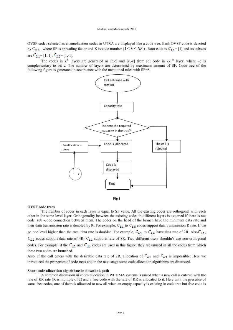
OVSF codes selected as channelization codes in UTRA are displayed like a code tree. Each OVSF code is denoted by CSF,k , where SF is spreading factor and K is code number ( )1 SFk . Root code is = [1] and its subsets
are = [1, 1], = [1,-1]. The codes in kth layers are generated as [c,c] and [c,-c] from [c] code in k-1th layer, where –c is
complementary to bit c. The number of layers are determined by maximum amount of SF. Code tree of the following figure is generated in accordance with the mentioned rules with SF=8.
Fig 1 OVSF code trees
The number of codes in each layer is equal to SF value. All the existing codes are orthogonal with each other in the same level layer. Orthogonality between the existing codes in different layers is assumed if there is not code, sub -code connection between them. The codes on the head of the branch have the minimum data rate and their data transmission rate is denoted by R. For example, to codes support data transmission R rate. If we
go one level higher than the tree, data rate is doubled. For example, to have data rate of 2R. Also ,
codes support data rate of 4R, supports rate of 8R. Two different users shouldn’t use non-orthogonal
codes. For example, if the and codes are used in this figure, they are unused in all the codes from which these two codes are branched. Also, if the call enters with the desirable data rate of 2R, allocation of and is impossible. Here we introduced the properties of code trees and in the next stage some code allocation algorithms are discussed. Short code allocation algorithms in downlink path
A common discussion in codes allocation in WCDMA systems is raised when a new call is entered with the rate of KR rate (K is multiple of 2) and a free code with the rate of KR is allocated to it. Here with the presence of some free codes, one of them is allocated to new all when an empty capacity is existing in code tree but free code is
Call entrance with rate KR
Capacity test
Is there the required capacity in the tree?
Code is allocated
Code is displayed
End
The call is rejected
Re-allocation is done
2951

J. Basic. Appl. Sci. Res., 1(12)2950-2959, 2011
not available for allocation, two different states are imagined. The first is rejecting call and the other is modifications and reallocation of codes for increasing space to accept call. As it is shown in this figure, if the call is entered with R rate, one of the existing codes in the head of branches are allocable except and . In the next stage if the
called enter with R rate, allocation of and codes causes some problems to the call entering with 2R rate or higher during code allocation.
Fig 2
Random code allocation algorithm This method is a primary algorithm for codes allocation. Briefly in this method if one or some codes with
KR rate are existing in code tree, randomly one of them is allocated to the call, otherwise the call is rejected. Random code allocation algorithm besides many problems is of some advantages regarding the allocation
speed of the codes. Anyway, to clarify the problems of this algorithm, in this figure shows that assumed code tree by accepting the calls with R rate and allocation of , , , randomly to them are in a bad situation. In this case if the call is entered with the rate of 2R or higher, even in spite of empty capacity in the tree, code allocation is not possible and the call will be rejected.
Another example of random code allocation algorithm is defined. The first call with the desired rate of 2R is entered and by assigning code all are unused. At this time and in case of entering call with
2R rate one of codes are selected randomly.
In this case by selecting code, indeed , , , will be unused and if the all with 4R data rate is entered, there is not a free code to assign to it.
As it was shown, the main advantages of this algorithm is high speed of code allocation and its simple execution in software calculations and the disadvantages of it are more blocking of code trees.
Random
Left
Left
Short code allocation
SF=6 Long code allocation
For each algorithm separately the probability blocking, bandwidth acceptance percent, total time of accepted conversations are calculated.
2952

Alikhani and Mohammadi, 2011
Left code allocation algorithm This algorithm shows better results in comparison with random code allocation. This method is based on
the fact that if one or some free codes with2R data rate are existing in code tree, the code is selected based on its location on the left side of code trees. It means that in case of the presence of some free codes in code tree, the left side free code is selected in code tree, otherwise the call is rejected. For better explanation of the algorithm consider the following figure: the primary call with R rate, is assigned to it and the next calls are
with , , codes. In this case code trees in the right side are empty and in case of entry of call with data rate of 2R and 4R code allocation is done easily.
Fig 3 As we saw in random code allocation algorithm and in case of selecting codes randomly, code tree is
blocked in case that 2R calls are entered. In the figure below the call with 2R rate is entered and according to this algorithm and among 4 codes
to code located in the left side of the code tree is allocated to them. In case that the call is entered
again with 2R rate, code is allocated to it. Here with the entrance of the calls with the data rate of R, 2R, 4R code is allocated to them and call rejection is occurred less.
In addition to two previous cases entrance traffics can be regarded as a combination of calls with R, 2R and 4R. Suppose that at first we have call with 2R rate. As it is shown in the figure, code is allocated to this call
and the next call is with the rate of 4R and at this time, cannot be allocated and only is delegated. Then, R
call is entered and code is allocated. The above example showed that left code allocation algorithm is a good solution for codes allocation and it had incredible advantages to random method. Optimization of allocation algorithms: General issue in all allocation algorithms is considering and selecting the algorithm based on the minimum probability is weakening bandwidth of the number of calls (blocking). Continuing the algorithm activity without optimization operation of the condition of code trees will be problematic. In the following code tree in a time interval 4 calls with R rate are entered consecutively and according allocation algorithm left codes dominate to codes, then a call with 4R rate is related to code. In this case code tree is active with the maximum capacity.
2953

J. Basic. Appl. Sci. Res., 1(12)2950-2959, 2011
The problem is raised when the members owning , codes and reject the call, in this case code trees are generated.
SF=1
SF=2
SF=4
SF=8
C1=[1]
C 2,1=[1,1] C2,2=[1,-1]
C4,2=[1,1,-1-1] C4,3=[1,-1,1,-1] C4,4=[1,-1,-1,1]
C8,1=[1,1,1,1,-1,-1,-1, -1] C8,8=[1,-1,-1,1,-1,1,1,-1]
OVSF tree codes
SF=1
SF=2
SF=4
SF=8
C1=1
c2,1=[1,1]
C4,3=[1, -1,1,-1] C4,4=[1,-1, -1,1]
C8,1=[1,1,1,1,-1, -1, -1, -1] C8,8=[1, -1,-1,1,-1,1,1, -1]
USED CODE
BLOCKED CODE
C2,2=[1,-1]
C4,1=[1,1,1,1]C4,2=[1,1,-1, -1]
Short code assignment algorithm in down link
SF=1
SF=2
SF=4
SF=8
C1=[1]
C 2,1=[1,1] C2,2=[1,-1]
C4,2=[1,1,-1-1] C4,3=[1,-1,1,-1] C4,4=[1,-1,-1,1]
C8,1=[1,1,1,1,-1,-1,-1,-1] C8,8=[1,-1,-1,1,-1,1,1,-1]
SF=1
SF=2
SF=4
SF=8
C1=[1]
C2,1=[1,1] C2,2=[1,-1]
C2,2=[1,1,-1-1] C4,3=[1,-1,1,-1] C4,4=[1,-1,-1,1]
C8,1=[1,1,1,1,-1,-1,-1,-1] C8,8=[1,-1,-1,1,-1,1,1,-1]
USED CODE
BLOCKED CODE
SF=1
SF=2
SF=4
C1=[1]
C 2,1=[1,1] C2,2=[1,-1]
C4,2=[1,1,-1-1] C4,3=[1,-1,1,-1] C4,4=[1,-1,-1,1]
C8,1=[1,1,1,1,-1,-1,-1,-1] C8,8=[1,-1,-1,1,-1,1,1,-1]
USED CODE
BLOCKED CODE
SF=1
SF=2
SF=4
SF=8
C1=[1]
C 2,1=[1,1] C2,2=[1,-1]
C4,2=[1,1,-1-1] C4,3=[1,-1,1,-1] C4,4=[1,-1,-1,1]
C8,1=[1,1,1,1, -1,-1,-1,-1] C8,8=[1,-1, -1,1, -1,1, 1,-1]
USED CODE
BLOCKED CODE
SF=1
SF=2
SF=4
SF=8
C1=[1]
C 2,1=[1,1] C2,2=[1,-1]
C4,2=[1,1,-1-1] C4,3=[1,-1,1,-1] C4,4=[1,-1,-1,1]
C8,1=[1,1,1,1,-1,-1,-1,-1] C8,8=[1,-1,-1,1,-1,1,1,-1]
USED CODE
BLOCKED CODE
2954

Alikhani and Mohammadi, 2011
SF=1
SF=2
SF=4
SF=8
C1=[1]
C 2,1=[1,1] C2,2=[1,-1]
C4,1=[1,1,1,1] C4,2=[1,1,-1-1] C4,3=[1,-1,1,-1] C4,4=[1,-1,-1,1]
C8,1=[1,1,1,1,-1,-1,-1,-1] C8,8=[1,-1,-1,1,-1,1,1,-1]
USED CODE
BLOCKED CODE
SF=1
SF=2
SF=4
SF=8
C1=[1]
C 2,1=[1,1] C2,2=[1,-1]
C4,1=[1,1,1,1] C4,2=[1,1,-1-1] C4,3=[1,-1,1,-1] C4,4=[1,-1,-1,1]
C8,1=[1,1,1,1,-1,-1,-1,-1] C8,8=[1,-1,-1,1,-1,1,1,-1]
USED CODE
BLOCKED CODE
SF=1
SF=2
SF=4
SF=8
C1=[1]
C 2,1=[1,1] C2,2=[1, -1]
C4,2=[1,1, -1-1] C4,3=[1,-1,1, -1] C4,4=[1, -1, -1,1]
C8,1=[1,1,1,1,-1,-1,-1, -1] C8,8=[1,-1,-1,1,-1,1,1, -1]
USED CODE
BLOCKED CODE
SF=1
SF=2
SF=4
SF=8
C1=[1]
C 2,1=[1,1] C2,2=[1,-1]
C4,2=[1,1,-1-1] C4,3=[1,-1,1,-1] C4,4=[1,-1,-1,1]
C8,1=[1,1,1,1,-1,-1,-1,-1] C8,8=[1,-1,-1,1,-1,1,1,-1]
USED CODE
BLOCKED CODE
SF=1
SF=2
SF=4
SF=8
C1=[1]
C 2,1=[1,1] C2,2=[1,-1]
C4,2=[1,1,-1-1] C4,3=[1,-1,1,-1] C4,4=[1,-1,-1,1]
C8,1=[1,1,1,1,-1,-1,-1,-1] C8,8=[1,-1,-1,1,-1,1,1,-1]
USED CODE
BLOCKED CODE
SF=1
SF=2
SF=4
SF=8
C1=[1]
C 2,1=[1,1] C2,2=[1,-1]
C4,2=[1,1,-1-1] C4,3=[1,-1,1,-1] C4,4=[1,-1,-1,1]
C8,1=[1,1,1,1,-1,-1,-1,-1] C8,8=[1,-1,-1,1,-1,1,1,-1]
USED CODE
BLOCKED CODE
2955

J. Basic. Appl. Sci. Res., 1(12)2950-2959, 2011
After this event, a new condition is occurred for this three. Here in case that 2R call is entered, even by empty capacity in code trees, code is not allocated and the call will be rejected. The important thing here is optimization of allocation algorithms and this can be called reallocation operation. Here besides introducing one method to solve the above problem, the related algorithm is introduced. Modified left code allocation algorithm: This algorithm introduced based on left algorithm is enjoying important advantages in comparison to two random and left algorithm. This is shown in the continuance of numerical results of simulation. The general flowchart of this algorithm and blocks duties are as the followings: Entering the new call: In the first stage the call enters with KR rate and request for code. Calculating capacity test: one of the advantages of this method in comparison with two previous methods is the presence of capacity test in the structure of this algorithm. At first we define capacity in code trees: According to the definition, the total capacity is the multiplication of the maximum number of branches head in the minimum data rate supported by code tree: Ct=N Rmin
In this equation N is the number of branches head and Rmin is the minimum data rate in the tree. In this case the occupied capacity is defined according the definition as: CO=NRRmin+N2R2Rmin+...NKRKRmin
Where, NR is the number of occupied codes with the rate of Rmin and N2R occupied codes with the rate of 2Rmin and finally the number of occupied codes with the rate of KR min . Now, the existing capacity of the network is obtained as : Ce=Ct-Co
Where in this equation Ce is the existing capacity and Ct ,Co are defined as the existing capacity and occupied capacity. Decision block of the presence of capacity: This block by comparing between the existing capacity of the tree and desired capacity of the call takes decision about future stages. If we have equation Ce> KR, KR call is directed to fourth block, otherwise the call is rejected. Adding this block increases the speed of calculations during codes allocation and will plan vital role in reducing delay of this algorithm. Code allocation block: This unit allocates suitable code to the entering call from the previous block. Code allocation in this unit is done based on modified left algorithm. In this algorithm selecting a good code is done according to the presence of free code in the left side of each layer of the tree. Code re-allocation block: The most important part of this algorithm is re-allocation of codes in different intervals and this reduces weakening of bandwidth and accepting more calls. Anyway, in the proposed algorithms during the entrance of each call, re-allocation process is done. The form of re-allocation is as transmission of the calls to the left side of the existing location in code trees. Code displaying block: In this block allocated code to each call is displayed. Call rejection block: If the equation Ce> KR is not satisfied, the call is rejected. Reviewing the performance of modified left algorithm
We consider the code trees in the following figure, two members with R rate left the network and it is not possible two accept 2R call. This is while cod tree has the capacity to accept the call with 2R rate. Modified left algorithm behavior such that after disconnecting two calls with R rate, the algorithm tries to optimized the existing condition and transfer the members to free code located in the left side of the code tree and the call with
transmits to .
As we can see by transmitting to , codes get free to be allocated to 2R calls or , . Another example to explain about the performance of algorithm is shown in the followings. Code trees accepted one 2R call in codes and also 3 R calls in , , .
After this member tries to exit the network, in this case if the call is entered with the required rate of 4R even with the empty space in the network, it is not possible to accept it. In this case the existing capacity in the network is calculated as the followings: As we can see even with 4R capacity in code trees, it is not possible to give service to the call with this rate. Here modified left algorithm by replacing and reallocating the existing codes to free code located in the left side of code tree; pave the way to accept new call. The call in transmits to and 4R member dominates code. The new condition of code trees is shown in the following figure.
2956
Alikhani and Mohammadi, 2011
Short codes allocation in uplink path: As it was shown in the previous sections, separation or channelization of members in this cell is done by OVSF codes. It is necessary to use a suitable code allocation algorithm in downlink path. In uplink path the data is sent from one user and the separation of different desirable services from one user is done by OVSF codes and due to the fact that unit user of code trees it is not necessary to have special code allocation algorithm. Due to similar code trees for all the users, it is possible to cancel the required service of one user by other users and due to this using one scrambling code (long) is vital to separate users.
Long codes allocation in WCDMA Long codes allocation in downlink path: Separation of cells in a geographical zone is done by long codes.
To each cell a unit scrambling code is allocated and this code is similar for all the users located in one cell. The selected codes for this aim are gold codes with the length of 241-1 chip. 512 of these codes are selected
to allocate them to the adjacent cells in one zone and the selection of more codes makes cell search process problematic. Due to high number of these codes of this family, using a special algorithm is not necessary.
Long codes allocation in uplink path: long codes in uplink path is applied as users separators and a separate code is allocated to the users in one cell and this code along with short code avoids interference between users in uplink path.
A lot of Kasami codes meet our demands in this section. Based on WCDMA standards, gold codes with the length of 218-1 meet our demands. Due to high number of Kasami codes, allocation of code to each user is very simple and it does not require any special allocation algorithm. Simulation, analysis and comparison is shown in modeling of simulator constituent blocks and their connection to each other. Statistical traffic generator: unpredictability of telecommunication networks traffic is mostly influenced by two random processes of the number of entrance of conversations and also duration of conversations. Entrance of each member to the network is totally independent of other members and the number of members’ entrance to the network in each time interval is totally separated from other time intervals. In this program the entrance of the members and conversation duration is totally considered random. As during simulation, traffic intensity criterion is considered as the entry parameter and response of different algorithms to it are considered. In the figure below members generation method is shown in this simulation and the required assumptions are as the followings: Conversation entry process to Poisson process is with entry rate of a. Conversation duration is distributed exponentially. As it is shown in the flowchart, simulator program by receiving the number of members, the maximum conversation and maximum delay generates traffic. These parameters are explained in the followings. a. The number of members: The number of members entering the algorithm during running program. b. The maximum conversation duration: It is the maximum time each member can be presented in the network, the selection of conversation duration for each member is occurred randomly during this interval. c. The maximum delay: The maximum delay between the entrances of members to the network is determined by this parameter, the delay duration is randomly in this time interval. Maximum delay parameter has major effect on entry rate parameters traffic intensity. d. Voice call member’s percent: Considering the random nature of desired bandwidth by users, its distribution prediction is not possible. But by traffic investigation of desired wide band of the members, we found that most of the calls are of voice type and they have the minimum bandwidth.
In this simulator to study the performance of various code allocation algorithms, it is possible to determine the number of voice members at the beginning of program run.
Simulator program by receiving above parameters generates members with various parameters and bandwidth. After generation of traffic, the calculations are done to obtain the average conversation duration of all the members and average entrance of members in time. These two values play vital role in generation of traffic intensity parameter. According to the definition, traffic intensity is : Traffic intensity= The average members entrance in time×Average conversation duration of all the members
Average entrance of the members in time: The selection of the number of members is done for testing the algorithm and by timer, total entrance time is calculated then these two values are divided by each other.
Average conversation duration of all the members: Averaging is done on all members conversation time, and then these two values are multiplied by each other. Long code allocation: Lone codes are applied in cells separations and the long code is selected among 512 standard codes in WCDMA and due to high amounts of these codes, there is no special algorithm for allocation and as simulation is done under one cell, this code is similar for all the generated members. Short code allocation: The main task of this paper is focused on this section. As it was said, the generated traffic in the previous stages enters this block after long code allocation (That is similar for all). Three introduced algorithms
2957
J. Basic. Appl. Sci. Res., 1(12)2950-2959, 2011
receive in parallel the generated traffic by statistical traffic generation source and allocate code to them. Due to randomized generated traffic, it is attempted to feed generated traffic at the same time as equally to all 3 algorithms during running simulator to have precise comparisons.
Flowchart of the simulated algorithm is shown in this figure. In block 1 capacity test is done and in block 2 decision is taken about the existence of empty capacity of KR in the tree to give service to all the calls. If the previous stage test is negative, the call is rejected.
If the capacity is adequate, traffic enters block 3 so that a proper code is allocated to it. As we can see, allocator benefits from 3 random, left and modified left algorithm to do the comparisons. Block 8 is responsible for re-allocation operation and is active only about modified left algorithm and in special time intervals the existing codes in the tree are re-allocated. In Block 4, decision is taken about code allocation and if the entered call receive proper code, we enter block 5. In block 5 the ratio of bandwidth received by tree is calculated to total entry bandwidth to calculate bandwidth output. The following equation shows this calculation: (Total bandwidth to tree/ total bandwidth received by tree)= band acceptance output In block 6, the ratio of accepted calls and total calls are calculated. In block 7, the ratio of accepted conversation time to total time entered by the network is calculated. If in block 4, a proper code is not allocated to the call, we should go to the new phase of calculations. In block 9, the percent of blocked bandwidth is calculated. According to the definition blocked bandwidth is: (Total bandwidth/ wasted bandwidth with empty capacity) = blocked bandwidth In block 10, the percent of blocked calls are calculated as the followings: (Total entered calls/ rejected calls with empty capacity) = The percent of block calls Simulation and analysis:
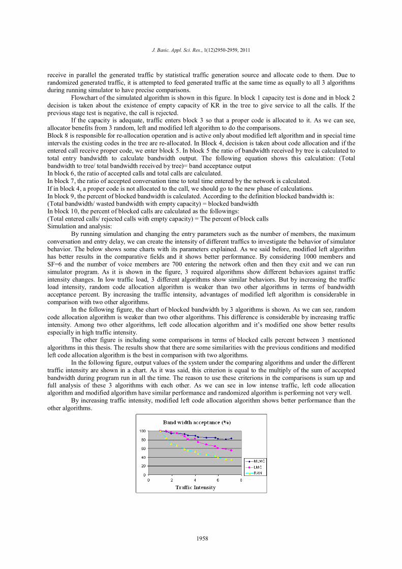
By running simulation and changing the entry parameters such as the number of members, the maximum conversation and entry delay, we can create the intensity of different traffics to investigate the behavior of simulator behavior. The below shows some charts with its parameters explained. As we said before, modified left algorithm has better results in the comparative fields and it shows better performance. By considering 1000 members and SF=6 and the number of voice members are 700 entering the network often and then they exit and we can run simulator program. As it is shown in the figure, 3 required algorithms show different behaviors against traffic intensity changes. In low traffic load, 3 different algorithms show similar behaviors. But by increasing the traffic load intensity, random code allocation algorithm is weaker than two other algorithms in terms of bandwidth acceptance percent. By increasing the traffic intensity, advantages of modified left algorithm is considerable in comparison with two other algorithms.
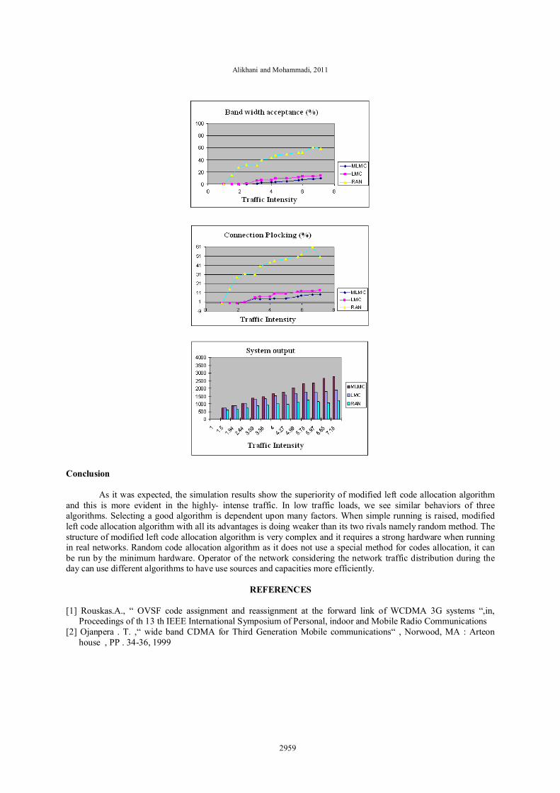
In the following figure, the chart of blocked bandwidth by 3 algorithms is shown. As we can see, random code allocation algorithm is weaker than two other algorithms. This difference is considerable by increasing traffic intensity. Among two other algorithms, left code allocation algorithm and it’s modified one show better results especially in high traffic intensity.
The other figure is including some comparisons in terms of blocked calls percent between 3 mentioned algorithms in this thesis. The results show that there are some similarities with the previous conditions and modified left code allocation algorithm is the best in comparison with two algorithms.
In the following figure, output values of the system under the comparing algorithms and under the different traffic intensity are shown in a chart. As it was said, this criterion is equal to the multiply of the sum of accepted bandwidth during program run in all the time. The reason to use these criterions in the comparisons is sum up and full analysis of these 3 algorithms with each other. As we can see in low intense traffic, left code allocation algorithm and modified algorithm have similar performance and randomized algorithm is performing not very well.
By increasing traffic intensity, modified left code allocation algorithm shows better performance than the other algorithms.
1958
Alikhani and Mohammadi, 2011
Conclusion As it was expected, the simulation results show the superiority of modified left code allocation algorithm
and this is more evident in the highly- intense traffic. In low traffic loads, we see similar behaviors of three algorithms. Selecting a good algorithm is dependent upon many factors. When simple running is raised, modified left code allocation algorithm with all its advantages is doing weaker than its two rivals namely random method. The structure of modified left code allocation algorithm is very complex and it requires a strong hardware when running in real networks. Random code allocation algorithm as it does not use a special method for codes allocation, it can be run by the minimum hardware. Operator of the network considering the network traffic distribution during the day can use different algorithms to have use sources and capacities more efficiently.
REFERENCES
[1] Rouskas.A., “ OVSF code assignment and reassignment at the forward link of WCDMA 3G systems “,in,
Proceedings of th 13 th IEEE International Symposium of Personal, indoor and Mobile Radio Communications [2] Ojanpera . T. ,“ wide band CDMA for Third Generation Mobile communications“ , Norwood, MA : Arteon
house , PP . 34-36, 1999
2959