EFG 213-320 - · PDF file09.09 - 03.13 51151902 EFG 213-320 Operating instructions G EFG 316...
243
09.09 - 03.13 51151902 EFG 213-320 Operating instructions G EFG 316 EFG 215 EFG 216k EFG 216 EFG 218k EFG 218 EFG 220 EFG 316k EFG 318k EFG 318 EFG 320 EFG 213
Transcript of EFG 213-320 - · PDF file09.09 - 03.13 51151902 EFG 213-320 Operating instructions G EFG 316...

09.09 -
03.13
51151902
EFG 213-320
Operating instructions G
EFG 316
EFG 215
EFG 216k
EFG 216
EFG 218k
EFG 218
EFG 220
EFG 316k
EFG 318k
EFG 318
EFG 320
EFG 213

3
03
.13
EN
Declaration of Conformity
Jungheinrich AG, Am Stadtrand 35, D-22047 HamburgManufacturer or agent acting in the European Union
Additional information
On behalf of
Date
G EU Conformity Declaration
The undersigned hereby declare that the powered industrial truck described below indetail complies with the European Directives 2006/42/EC (Machinery Directive) and2004/108/EEC (Electromagnetic Compatibility - EMC) including amendments as wellas the legislative decree to incorporate the directives in national law. The signatoriesare in each case individually authorized to compile the technical documents.
Type Option Serial no. Year of manufacture
EFG 213 EFG 215 EFG 216k EFG 216 EFG 218k EFG 218 EFG 220 EFG 316k EFG 316 EFG 318k EFG 318 EFG 320

03
.13
EN
4
5
03
.13
EN
Foreword
Notes on the operating instructions
The present ORIGINAL OPERATING INSTRUCTIONS are designed to providesufficient instruction for the safe operation of the industrial truck. The information isprovided clearly and concisely. The chapters are arranged by letter and the pages arenumbered continuously.
The operator manual details different industrial truck models. When operating andservicing the industrial truck, make sure that the particular section applies to yourtruck model.
Our trucks are subject to ongoing development. Jungheinrich reserves the right toalter the design, equipment and technical features of the system. No guarantee ofparticular features of the truck should therefore be assumed from the presentoperating instructions.
Safety notices and text mark-ups
Safety instructions and important explanations are indicated by the followinggraphics:
DANGER!
Indicates an extremely hazardous situation. Failure to comply with this instruction willresult in severe irreparable injury and even death.
WARNING!
Indicates an extremely hazardous situation. Failure to comply with this instructionmay result in severe irreparable injury and even death.
CAUTION!
Indicates a hazardous situation. Failure to comply with this instruction may result inslight to medium injury.
NOTE
Indicates a material hazard. Failure to comply with this instruction may result inmaterial damage.
Z Used before notices and explanations.
t Indicates standard equipment
o Indicates optional equipment

03
.13
EN
6
Copyright
Copyright of these operating instructions remains with JUNGHEINRICH AG.
Jungheinrich Aktiengesellschaft
Am Stadtrand 3522047 Hamburg - Germany
Tel: +49 (0) 40/6948-0
www.jungheinrich.com

7
03
.13
EN
Contents
A Correct Use and Application ................................................... 11
1 General.................................................................................................... 112 Correct application................................................................................... 113 Approved application conditions.............................................................. 124 Proprietor responsibilities ........................................................................ 135 Adding attachments and/or optional equipment ...................................... 13
B Truck Description .................................................................... 15
1 Application ............................................................................................... 151.1 Truck models and rated capacity............................................................. 152 Assemblies and Functional Description................................................... 162.1 Travel direction definition......................................................................... 162.2 Assembly Overview ................................................................................. 172.3 Functional Description ............................................................................. 183 Technical Specifications .......................................................................... 193.1 Performance data .................................................................................... 203.2 Dimensions.............................................................................................. 223.3 Weights.................................................................................................... 283.4 Mast versions .......................................................................................... 293.5 Tyre type.................................................................................................. 303.6 Engine Data............................................................................................. 313.7 EN norms................................................................................................. 323.8 Conditions of use..................................................................................... 333.9 Electrical requirements ............................................................................ 334 Identification points and data plates ........................................................ 344.1 Indication Points ...................................................................................... 344.2 Data plate ................................................................................................ 364.3 Truck capacity plate................................................................................. 374.4 Attachment capacity plate ....................................................................... 385 Stability .................................................................................................... 38
C Transport and Commissioning ................................................ 39
1 Transport ................................................................................................. 392 Truck laden.............................................................................................. 392.1 Centre of gravity of the truck ................................................................... 392.2 Lifting the truck by crane ......................................................................... 402.3 Loading with another industrial truck ....................................................... 423 Securing the truck during transport ......................................................... 434 Using the Truck for the First Time ........................................................... 45

03
.13
EN
8
D Battery - Servicing, Recharging, Replacement ....................... 47
1 Safety Regulations Governing the Handling of Lead-Acid Batteries ....... 471.1 General notes on handling batteries........................................................ 492 Battery types............................................................................................ 502.1 Battery dimensions .................................................................................. 513 Exposing the battery................................................................................ 524 Charging the battery ................................................................................ 534.1 Charging the battery with a stationary charger........................................ 534.2 Charging the battery with an on-board charger ....................................... 545 Battery removal and installation .............................................................. 585.1 Battery holder assembly .......................................................................... 595.2 Removal and installation using an EJE pallet truck with Snapfit battery
holder (o) ................................................................................................ 615.3 Removal and installation using a hand pallet truck with Snapfit battery
holder (o) ................................................................................................ 645.4 Removal and installation using a multi-adapter (o) ................................ 675.5 Removal and installation using a worktable for crane loading (o) .......... 695.6 Removal and installation using a fork shoe (o) ...................................... 715.7 Removal and installation using a roller conveyor (o).............................. 735.8 Hook-on battery door removal and installation (o) ................................. 74
E Operation ................................................................................ 75
1 Safety Regulations for the Operation of the Forklift Truck....................... 752 Displays and Controls.............................................................................. 772.1 Control panel with display unit ................................................................. 812.2 Armrest control panel switch (o)............................................................. 852.3 Side compartment control panel switch (o) ............................................ 862.4 Display..................................................................................................... 873 Preparing the Truck for Operation ........................................................... 903.1 Checks and operations to be performed before starting daily operation . 903.2 Entry and exit........................................................................................... 933.3 Trucks with reduced headroom (o)......................................................... 933.4 Setting up the operator position............................................................... 943.5 Seat Belt .................................................................................................. 984 Industrial Truck Operation ....................................................................... 1004.1 Safety regulations for truck operation...................................................... 1004.2 Preparing the truck for operation ............................................................. 1034.3 Setting the time........................................................................................ 1044.4 Parking the truck securely ....................................................................... 1054.5 Emergency Disconnect............................................................................ 1064.6 Travel....................................................................................................... 1074.7 Steering ................................................................................................... 1094.8 Brakes ..................................................................................................... 1104.9 Adjusting the forks ................................................................................... 1144.10 Replacing the forks.................................................................................. 1154.11 Lifting, transporting and depositing loads ................................................ 1164.12 Operating the lift mechanism and integrated attachments ...................... 1184.13 Safety instructions for operating additional attachments ......................... 1254.14 Operating additional attachments for the SOLO-PILOT .......................... 129
9
03
.13
EN
4.15 Operating additional attachments for the Multi Pilot ................................ 1314.16 Fitting additional attachments.................................................................. 1335 Towing trailers ......................................................................................... 1356 Optional equipment ................................................................................. 1376.1 CanCode keypad..................................................................................... 1376.2 Assistance systems ................................................................................. 1416.3 Steel cab.................................................................................................. 1436.4 Sliding windows ....................................................................................... 1446.5 Automatic / mechanical folding gate........................................................ 1456.6 Panel door ............................................................................................... 1466.7 Operator position extension..................................................................... 1466.8 Adjusting the driver’s seat ....................................................................... 1476.9 Heating .................................................................................................... 1486.10 Removable load backrest ........................................................................ 1496.11 Lift cutout override ................................................................................... 1496.12 Fire extinguisher ...................................................................................... 1506.13 Tilt angle display...................................................................................... 1506.14 Rockinger coupling with hand lever or remote control............................. 1516.15 Camera system ....................................................................................... 1526.16 Control layout “N” .................................................................................... 1537 Troubleshooting....................................................................................... 1547.1 Troubleshooting....................................................................................... 1547.2 Operating the truck without its own drive system .................................... 1567.3 Emergency lowering ................................................................................ 159
F Industrial Truck Maintenance .................................................. 161
1 Operational Safety and Environmental Protection................................... 1612 Maintenance Safety Regulations............................................................. 1622.1 Consumables and used parts.................................................................. 1632.2 Wheels..................................................................................................... 1632.3 Lift Chains................................................................................................ 1642.4 Hydraulic system ..................................................................................... 1653 Lubricants and Lubrication Schedule ...................................................... 1663.1 Handling consumables safely.................................................................. 1663.2 Lubrication Schedule ............................................................................... 1683.3 Consumables........................................................................................... 1694 Maintenance and repairs ......................................................................... 1714.1 Preparing the truck for maintenance and repairs .................................... 1714.2 Lifting and jacking up the truck safely...................................................... 1724.3 Opening the rear panel............................................................................ 1734.4 Checking the wheel attachments............................................................. 1744.5 Replacing wheels .................................................................................... 1754.6 Hydraulic system ..................................................................................... 1774.7 Replacing the hydraulic oil filter............................................................... 1794.8 Replacing the ventilation/discharge filter ................................................. 1794.9 Check the gear oil level ........................................................................... 1804.10 Heating .................................................................................................... 1814.11 Adding window washer system fluid........................................................ 1814.12 Checking electrical fuses......................................................................... 1824.13 Cleaning .................................................................................................. 1864.14 Working on the electrical system............................................................. 189

03
.13
EN
10
4.15 Restoring the truck to service after maintenance and repairs ................. 1905 Decommissioning the industrial truck ...................................................... 1915.1 Prior to decommissioning ........................................................................ 1925.2 During decommissioning ......................................................................... 1925.3 Restoring the truck to service after decommissioning ............................. 1936 Safety tests to be performed at intervals and after unusual incidents ..... 1947 Final de-commissioning, disposal............................................................ 1958 Human vibration measurement ............................................................... 1959 Servicing and Inspection ......................................................................... 19610 Maintenance checklist EFG 213-220....................................................... 19710.1 Operating company ................................................................................. 19710.2 Customer service..................................................................................... 20011 Maintenance checklist EFG 316-320....................................................... 20811.1 Operating company ................................................................................. 20811.2 Customer service..................................................................................... 211

1
05
06.G
B
Appendix
JH Traction Battery Operating Instructions
Z These operating instructions apply only to Jungheinrich battery models. If usinganother brand, refer to the manufacturer's operating instructions.

05
06.G
B
2

11
03
.13
EN
A Correct Use and Application
1 General
The truck must be used, operated and serviced in accordance with the presentinstructions. All other types of use are beyond its scope of application and may resultin damage to personnel, the industrial truck or property.
2 Correct application
NOTE
The maximum load and load distance are indicated on the capacity plate and mustnot be exceeded.The load must rest on the load handler or be lifted by an attachment approved by themanufacturer.The load must be fully raised,see "Lifting, transporting and depositing loads" onpage 116.
– Lifting and lowering loads.
– Transporting lowered loads over short distances.
– Do not travel with a raised load (>30 cm).
– Do not carry or lift passengers.
– Do push or pull load units.
– Occasional towing of trailer loads.
– When towing trailer loads the load must be secured on the trailer.
– The permissible trailer load must not be exceeded.

03
.13
EN
12
3 Approved application conditions
– Operation in industrial and commercial environments.
– Permissible temperature range -20°C to 40°C.
– Operation only on secure, level surfaces with sufficient capacity.
– Do not exceed the permissible surface and spot load limits on the travel routes.
– Operation only on routes that are visible and approved by the operating company.
– Negotiating inclines up to a maximum of 15 %.
– Do not travel across or at an angle on inclines. Travel with the load facing uphill.
– Operation in partially public traffic.
WARNING!
Use under extreme conditions
Using the truck under extreme conditions can result in malfunctions and accidents.
Special equipment and authorisation are required if the truck is to be constantlyused in extreme conditions, especially in dusty or corrosive atmospheres.
The truck cannot be used in areas at risk of explosion.
In adverse weather conditions (thunder, lightning) the industrial truck must not beoperated outside or in endangered areas.
13
03
.13
EN
4 Proprietor responsibilities
For the purposes of the present operating instructions the “operating company” isdefined as any natural or legal person who either uses the industrial truck himself, oron whose behalf it is used. In special cases (e.g. leasing or renting) the proprietor isconsidered the person who, in accordance with existing contractual agreementsbetween the owner and user of the industrial truck, is charged with operational duties.The proprietor must ensure that the industrial truck is used only for the purpose it isintended for and that danger to life and limb of the user and third parties are excluded.Furthermore, accident prevention regulations, safety regulations and operating,servicing and repair guidelines must be followed. The operating company mustensure that all users have read and understood these operating instructions.
NOTE
Failure to comply with the operating instructions invalidates the warranty. The sameapplies if improper work is carried out on the truck by the customer or third partieswithout the permission of the manufacturer.
5 Adding attachments and/or optional equipment
The mounting or installation of additional equipment which affects or enhances theperformance of the industrial truck requires the written permission of themanufacturer. Local authority approval may also need to be obtained.Local authority approval however does not constitute the manufacturer’s approval.

03
.13
EN
14

15
03
.13
EN
B Truck Description
1 Application
The EFG 213-320 is a three- or four-wheel electric sit-down counterbalanced truck. Itis a cantilever counterbalanced truck which can lift, transport and deposit loads usingthe load handler attached in front.Closed bottom pallets can also be lifted.
1.1 Truck models and rated capacity
The rated capacity depends on the model. The rated capacity can be derived fromthe model name.
The rated capacity is not generally the same as the permissible capacity. Thecapacity can be found on the capacity plate attached to the truck.
EFG213
EFG Model name
2 Series
13 Rated capacity x 100 kg

03
.13
EN
16
2 Assemblies and Functional Description
2.1 Travel direction definition
The following determinations have been made for travel direction specification:
The following conventions have been agreed for travel direction specification:
Item Travel direction
1 Links
2 Reverse
3 Forward
4 Right
1
2 3
4

17
03
.13
EN
2.2 Assembly Overview
Item Component Item Component
1 t Driver's seat 8 t Fork tines
2 t Overhead guard 9 t Fork carriage
3 t Mast 10 t Drive system
4 t Steering wheel 11 t Battery door
5 t Lifting mechanism control 12 t Steer axle
6 t Control and display unit 13 t Trailer coupling
7 t Emergency Disconnect switch
14 t Counterweight
t Standard equipment
1 2
4
3
6
5
7
8
9
10
1114 1213
03
.13
EN
18
2.3 Functional Description
Chassis
The chassis, in conjunction with the counterweight, forms the supporting basestructure of the truck. It is used to support the main components.
Operator position and overhead guard
The overhead guard comes in a range of models and protects the operator fromfalling objects and other external influences. All the controls are ergonomically arranged. The steering column anddriver's seat can be adjusted individually.
The controls and warnings on the control and display unit enable the system to bemonitored during operation, thereby ensuring a very high level of safety.
Steering
The electric steering offers a high level of efficiency and ergonomics. The height andtilt angle of the steering column are adjustable and can be set to suit all operators.The low cross-section means the operator has maximum legroom at all times. The steering is particularly smooth, offering a high level of efficiency. As a result the overall energy consumption is reduced significantly. The steer angle is shown in the display.
Wheels
There is a choice of super elastic or fully rubber tyres as well as optional pneumatic tyres.
Drive and brake system
The 2 motor front drive provides maximum traction to the drive wheels at all times.When cornering, the exact speed required for the wheel on the inside or outside ofthe bend respectively is set in proportion to the steer angle.
The service brake is a maintenance-free disk brake. The truck also brakesregeneratively via the drive motors. The energy recovered in the process is fed backto the battery.
The parking brake operates both automatically and manually.

19
03
.13
EN
Emergency Stop safety feature
If the system recognises a fault in the steering, an emergency stopis automatically introduced. The truck brakes to a halt, the travel direction does notchange.An event message is shown in the control and display unit. The truck performs a self-testwhenever it is switched on. Travel is only enabled againwhen the truck is operational and the parking brake (= emergency stop) released.
Hydraulic system
A multi-pilot valve allows for sensitive operation of the functions via the controls. Aspeed-controlled hydraulic pump ensures a proportionate and efficient supply to thehydraulic functions.
Mast
Two or three-stage masts, optionally with free lift function; narrow mast sectionsensure excellent visibility of the forks and attachments. Fork carriage and mast runon permanently lubricated and hence maintenance-free support rollers.
Attachments
The trucks can be optionally fitted with mechanical and hydraulic attachments.
3 Technical Specifications
All technical details refer to standard trucks.Values indicated with *) may vary, depending on the types of equipment used (e.g. mast, cabin, tyres etc.).
Z The technical specifications comply with the German "Industrial Truck Data Sheet"Guidelines.Technical modifications and additions reserved.
03
.13
EN
20
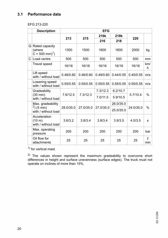
3.1 Performance data
1) for vertical mast.
2) The values shown represent the maximum gradeability to overcome shortdifferences in height and surface unevenness (surface edges). The truck must notoperate on inclines of more than 15%.
EFG 213-220
Description EFG
213 215216k 218k
220216 218
Q Rated capacity (whereC = 500 mm)1)
1300 1500 1600 1800 2000 kg
C Load centre 500 500 500 500 500 mm
Travel speed16/16 16/16 16/16 16/16 16/16
km/h
Lift speedwith / without load
0.48/0.60 0.46/0.60 0.49/0.60 0.44/0.55 0.40/0.55 m/s
Lowering speedwith / without load
0.55/0.55 0.55/0.55 0.55/0.55 0.55/0.55 0.55/0.55 m/s
Gradeability(30 min)with / without load
7.6/12.5 7.3/12.37.3/12.3 6.2/10.7
5.7/10.4 %7.0/11.5 5.9/10.5
Max. gradeability2) (5 min)with / without load
28.0/35.0 27.0/35.0 27.0/35.026.0/35.0
24.0/35.0 %25.0/35.0
Acceleration(10 m)with / without load
3.6/3.2 3.8/3.4 3.8/3.4 3.9/3.5 4.0/3.5 s
Max. operating pressure
200 200 200 200 200 bar
Oil flow for attachments
25 25 25 25 25l/
min

21
03
.13
EN
EFG 316-320
1) for vertical mast.
2) The values shown represent the maximum gradeability to overcome shortdifferences in height and surface unevenness (surface edges). The truck must notoperate on inclines of more than 15%.
Description EFG
316k 316 318k 318 320
Q Ratedcapacity (where C = 500 mm)1)
1600 1600 1800 1800 2000 kg
C Load centre 500 500 500 500 500 mm
Travel Speed *17/17 17/17 17/17 17/17 17/17
km/h
Lift speedw / w.o. load
0.49/0.60 0.49/0.60 0.44/0.55 0.44/0.55 0.40/0.55 m/s
Lowering speedw / w.o. load
0.55/0.55 0.55/0.55 0.55/0.55 0.55/0.55 0.55/0.55 m/s
Gradeability(30 min)w./w.o. load
7.3/12.3 7.0/11.5 6.2/10.7 5.9/10.5 5.7/10.4 %
Max. gradeability 2)(5 min)w./w.o. load
27.0/35.0 27.0/35.0 26.0/35.0 25.0/35.0 24.0/35.0 %
Acceleration(10 m)w./w.o. load
3.8/3.4 3.8/3.4 3.9/3.5 3.9/3.5 4.0/3.5 s
Max. operating pressure
200 200 200 200 200 bar
Oil flow for attachments
25 25 25 25 25l/
min

03
.13
EN
22
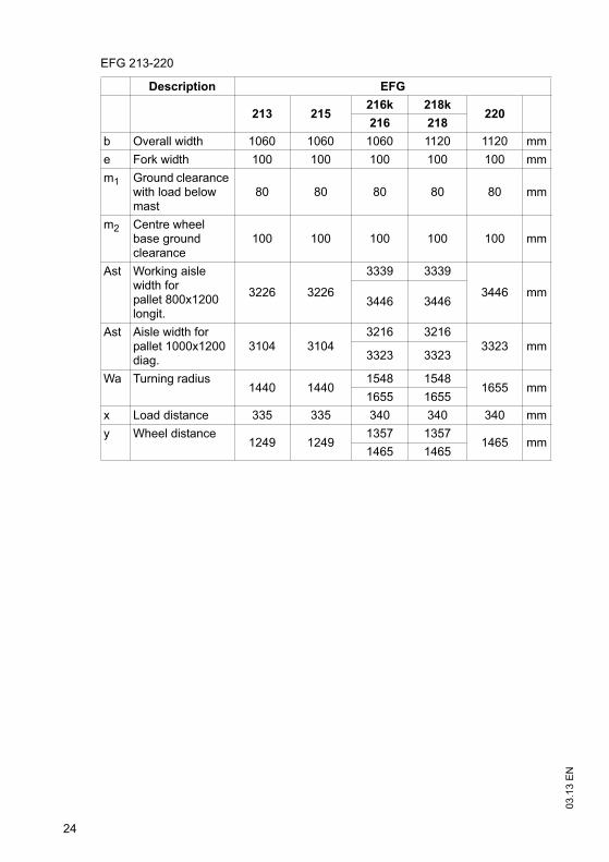
3.2 Dimensions
EFG 213-220
Description EFG
213 215216k 218k
220216 218
a/2 Safety distance 100 100 100 100 100 mm
h1 Mast height retracted
2000 2000 2000 2000 2000 mm
h2 Free lift 150 150 150 150 150 mm
h3 Lift 3000 3000 3000 3000 3000 mm
h4 Mast height extended
3560 3560 3560 3587 3587 mm
h6 Overhead guard height
2040 2040 2040 2040 2040 mm
h7 Seat height 920 920 920 920 920 mm
h10 Coupling height 560 560 560 560 560 mm
Mast tilt, fwd. 7 7 7 7 7 °
Mast tilt, back 7 7 7 7 7 °
L1 Length including forks 2924 2924
3037 30373145
mm
3145 3145 mm
L2 Headlength1774 1774
1887 18871995 mm
1995 1995

23
03
.13
EN
h6
h7h
y
l
x
10
m
2
1
m 2
L 2
h 2
h1h3
h4
L 1
l 6
b12
R Wa
b
a
e
c
Q
A st
2a
03
.13
EN
24
EFG 213-220
Description EFG
213 215216k 218k
220216 218
b Overall width 1060 1060 1060 1120 1120 mm
e Fork width 100 100 100 100 100 mm
m1 Ground clearance with load below mast
80 80 80 80 80 mm
m2 Centre wheel base ground clearance
100 100 100 100 100 mm
Ast Working aisle width for pallet 800x1200 longit.
3226 3226
3339 3339
3446 mm3446 3446
Ast Aisle width forpallet 1000x1200 diag.
3104 31043216 3216
3323 mm3323 3323
Wa Turning radius1440 1440
1548 15481655 mm
1655 1655
x Load distance 335 335 340 340 340 mm
y Wheel distance1249 1249
1357 13571465 mm
1465 1465

25
03
.13
EN
h6
h7h
y
l
x
10
m
2
1
m 2
L 2
h 2
h1h3
h4
L 1
l 6
b12
R Wa
b
a
e
c
Q
A st
2a

03
.13
EN
26
EFG 316-320
Description EFG
316k 316 318k 318 320
a/2 Safety distance 100 100 100 100 100 mm
h1 Mast height retracted
2000 2000 2000 2000 2000 mm
h2 Free lift 150 150 150 150 150 mm
h3 Lift 3000 3000 3000 3000 3000 mm
h4 Mast height extended
3560 3560 3587 3587 3587 mm
h6 Overhead guard height
2040 2040 2040 2040 2040 mm
h7 Seat height 920 920 920 920 920 mm
h10 Coupling height 410/580 410/580 410/580 410/580 410/580 mm
Mast tilt, fwd. 7 7 7 7 7 °
Mast tilt, back 7 7 7 7 7 °
L1 Length including forks
3140 3248 3140 3248 3248 mm
L2 Headlength 1990 2098 1990 2098 2098 mm
b Overall width 1060 1060 1120 1120 1120 mm
e Fork width 100 100 100 100 100 mm
m1 Ground clearance with load below mast
80 80 80 80 80 mm
m2 Centre wheel base ground clearance
100 100 100 100 100 mm
Ast Working aisle width for pallet 800x1200 longit.
3599 3725 3599 3725 3725 mm
Ast Aisle width forpallet 1000x1200 transv.
3403 3526 3403 3526 3526 mm
Wa Turning radius 1859 1985 1859 1985 1985 mm
x Load distance 340 340 340 340 340 mm
y Wheel distance 1400 1508 1400 1508 1508 mm

27
03
.13
EN
h6
h7h
y
l
x
10
ms
2
1
m 2
L 2
h 2
h1h3
h4
L 1
l 6
b12 b
R
13
Wa
b
a
e
c
Q
A st
2a
03
.13
EN
28
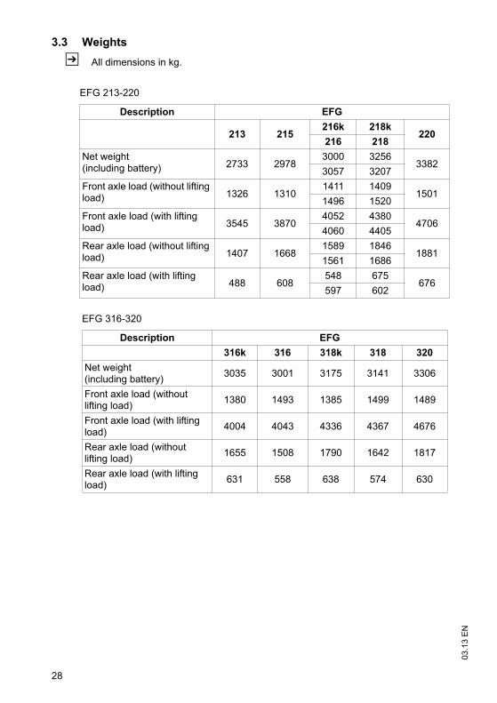
3.3 Weights
Z All dimensions in kg.
EFG 213-220
Description EFG
213 215216k 218k
220216 218
Net weight(including battery) 2733 2978
3000 32563382
3057 3207
Front axle load (without lifting load) 1326 1310
1411 14091501
1496 1520
Front axle load (with lifting load) 3545 3870
4052 43804706
4060 4405
Rear axle load (without lifting load) 1407 1668
1589 18461881
1561 1686
Rear axle load (with lifting load) 488 608
548 675676
597 602
EFG 316-320
Description EFG
316k 316 318k 318 320
Net weight(including battery)
3035 3001 3175 3141 3306
Front axle load (without lifting load)
1380 1493 1385 1499 1489
Front axle load (with lifting load)
4004 4043 4336 4367 4676
Rear axle load (without lifting load)
1655 1508 1790 1642 1817
Rear axle load (with lifting load)
631 558 638 574 630
29
03
.13
EN
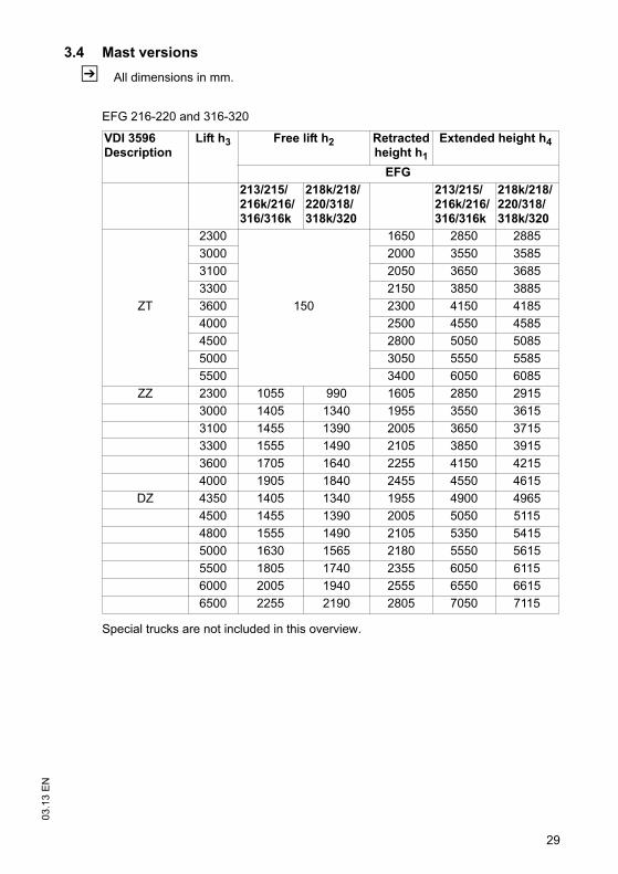
3.4 Mast versions
Z All dimensions in mm.
Special trucks are not included in this overview.
EFG 216-220 and 316-320
VDI 3596Description
Lift h3 Free lift h2 Retractedheight h1
Extended height h4
EFG
213/215/216k/216/316/316k
218k/218/220/318/318k/320
213/215/216k/216/316/316k
218k/218/220/318/318k/320
ZT
2300
150
1650 2850 2885
3000 2000 3550 3585
3100 2050 3650 3685
3300 2150 3850 3885
3600 2300 4150 4185
4000 2500 4550 4585
4500 2800 5050 5085
5000 3050 5550 5585
5500 3400 6050 6085
ZZ 2300 1055 990 1605 2850 2915
3000 1405 1340 1955 3550 3615
3100 1455 1390 2005 3650 3715
3300 1555 1490 2105 3850 3915
3600 1705 1640 2255 4150 4215
4000 1905 1840 2455 4550 4615
DZ 4350 1405 1340 1955 4900 4965
4500 1455 1390 2005 5050 5115
4800 1555 1490 2105 5350 5415
5000 1630 1565 2180 5550 5615
5500 1805 1740 2355 6050 6115
6000 2005 1940 2555 6550 6615
6500 2255 2190 2805 7050 7115
03
.13
EN
30
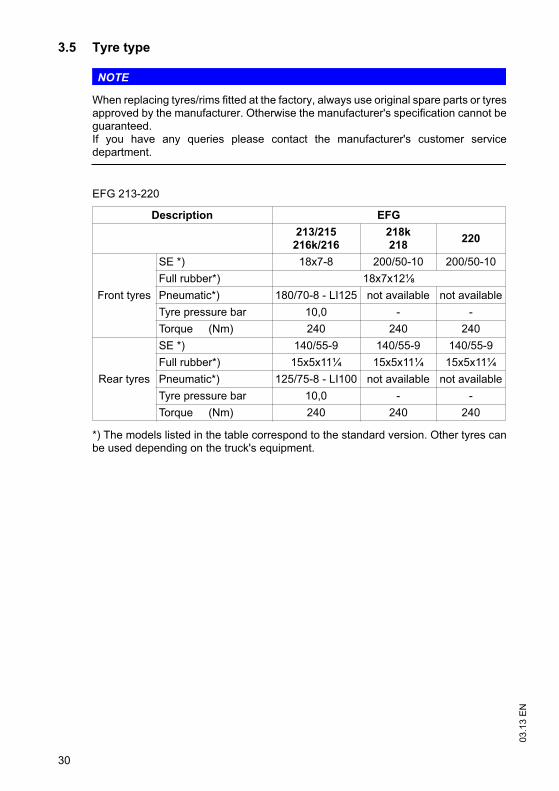
3.5 Tyre type
NOTE
When replacing tyres/rims fitted at the factory, always use original spare parts or tyresapproved by the manufacturer. Otherwise the manufacturer's specification cannot beguaranteed.If you have any queries please contact the manufacturer's customer servicedepartment.
*) The models listed in the table correspond to the standard version. Other tyres canbe used depending on the truck's equipment.
EFG 213-220
Description EFG
213/215216k/216
218k218
220
Front tyres
SE *) 18x7-8 200/50-10 200/50-10
Full rubber*) 18x7x12
Pneumatic*) 180/70-8 - LI125 not available not available
Tyre pressure bar 10,0 - -
Torque (Nm) 240 240 240
Rear tyres
SE *) 140/55-9 140/55-9 140/55-9
Full rubber*) 15x5x11¼ 15x5x11¼ 15x5x11¼
Pneumatic*) 125/75-8 - LI100 not available not available
Tyre pressure bar 10,0 - -
Torque (Nm) 240 240 240

31
03
.13
EN
*) The models listed in the table correspond to the standard version. Other tyres canbe used depending on the truck's equipment.
3.6 Engine Data
EFG 316-320
Description EFG
316k316
318k318
320
Front tyres
SE *) 18x7-8 200/50-10 200/50-10
Full rubber*) 18x7x12 18x7x12 18x7x12
Pneumatic*) 180/70-8 - LI125(PR 16)
not available not available
Tyre pressure bar 10,0 - -
Torque (Nm) 240 240 240
Rear tyres
SE *) 16x6-8 16x6-8 16x6-8
Full rubber*) 15x5x11¼ 15x5x11¼ 15x5x11¼
Pneumatic*) 150/75-8 - LI113(PR 16)
not available not available
Tyre pressure bar 10,0 - -
Torque (Nm) 240 240 240
EFG 216-220 and 316-320
Description EFG
213 / 215 / 216k / 216218k / 218 / 220
316k / 316 / 318k / 318320
Drive motor 2 x 4.5kW 2 x 4.5kW
Lift motor 11.5kW 11.5kW
Steer motor 0.9kW 0.9kW
03
.13
EN
32
3.7 EN norms
Noise emission level
– EFG 213-220: 68 dB(A)
– EFG 316-320: 67 dB(A)
*+/- 3 dB(A) depending on the truck's equipment
in accordance with EN 12053 as harmonised with ISO 4871.
Z The noise emission level is calculated in accordance with standard procedures andtakes into account the noise level when travelling, lifting and when idle. The noiselevel is measured at the level of the driver's ear.
Vibration
– EFG 213-220: 0,53m/s²
– EFG 316-320: 0,51 m/s²
in accordance with EN 13059.
Z The vibration acceleration acting on the body in the operating position is, inaccordance with standard procedures, the linearly integrated, weightedacceleration in the vertical direction. It is calculated when travelling over thresholdsat constant speed (standard truck version). These recordings were taken on asingle occasion and must not be confused with the human vibrations of the "2002/44/EC/Vibrations" operator directive. The manufacturer offers a special service tomeasure these human vibrations, see "Human vibration measurement" onpage 195.
Electromagnetic compatibility (EMC)
The manufacturer confirms that the truck adheres to the limits for electromagneticemissions and resistance as well as the static electricity discharge test in accordancewith EN 12895 as well as the standardised instructions contained therein.
Z No changes to electric or electronic components or their arrangement may bemade without the written agreement of the manufacturer.
WARNING!
Medical equipment can be damaged by non-ionised radiation
Electrical equipment on the truck emitting non-ionised radiation (e.g. wireless datatransmission) can affect operators' medical equipment (pacemakers, hearing aidsetc.) and result in malfunctions. Consult with a doctor or the medical equipmentmanufacturer to clarify whether it can be used near the industrial truck.

33
03
.13
EN
3.8 Conditions of use
Ambient temperature
– operating at -20°C to 40°C
Z Special equipment and authorisation are required if the truck is to be usedcontinually in conditions of extreme temperature or condensing air humidityfluctuations.
3.9 Electrical requirements
The manufacturer certifies compliance with the requirements for the design andmanufacture of electrical equipment, according to EN 1175 "Industrial Truck Safety -Electrical Requirements", provided the truck is used according to its purpose.
03
.13
EN
34
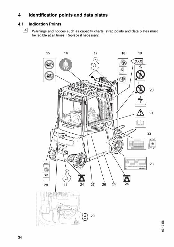
4 Identification points and data plates
4.1 Indication Points
Z Warnings and notices such as capacity charts, strap points and data plates mustbe legible at all times. Replace if necessary.
D (mm)
(mm) Q (kg)
XXX
1716 18 1915
20
22
23
24252627241728
21
29

35
03
.13
EN
Item Component
15 Do not drive, or operate the forward tilt, with the load in the raised position
16 Wear seat belt
17 Strap points for crane lifting
18 Tipover caution, no passengers
19 Lift limit
20 Do not step onto or beneath the load, risk of trapping with moving mast
21 Read operating instructions
22 Capacity (or reduced capacity)
23 Data plate, behind the battery door
24 Jack contact points
25 Model description
26 Risk of trapping, in chassis behind the battery door
27 Serial number, on chassis behind the battery door
28 Test plaque (o)
29 Add hydraulic oil

03
.13
EN
36
4.2 Data plate
Z The illustration shows the standard version for EU member states. The data platemay differ in other countries.
Z For queries regarding the truck or ordering spare parts always quote the truck serialnumber (31).
30 31 3332 34
41
37
40
39
38
3635
Item Description Item Description
30 Type 36 Year of manufacture
31 Serial number 37 Load centre (mm)
32 Rated capacity (kg) 38 Output
33 Battery voltage (V) 39 Min./max. battery weight (kg)
34 Net weight w.o. battery (kg) 40 Manufacturer
35 Option 41 Manufacturer’s logo

37
03
.13
EN
4.3 Truck capacity plate
CAUTION!
Accident risk from fork replacement
If you replace the forks with ones that differ from the originals, the capacity willchange.
When replacing the forks you must attach an additional capacity plate to the truck.
Trucks supplied without forks are given a capacity plate for standard forks (length:1150 mm).
The capacity plate (22) gives the capacity (Q in kg) of the truck for a vertical mast.The maximum capacity is shown as a table with a given load centre of gravity D (inmm) and the required lift height H (in mm).
The capacity plate (22) of the truck indicates the truck's capacity with the forks asoriginally supplied.
Example of how to calculate the maximum capacity:
For a load centre of gravity D of 600 mm and a max. lift height h3 of 3600 mm themaximum capacity Q is 1105 kg.
Lift height restriction
The arrow shaped markings (42 and 43) on theinner and outer masts show the operator whenthe prescribed lift limits have been reached.
D (mm) 500 600 700
h3 (mm)
4250
3600
2900
850
1105
1250
850
1105
1250
600
850
850
Q (kg)
22
42 43
03
.13
EN
38
4.4 Attachment capacity plate
The attachment capacity plate is next to the truck's capacity plate and gives thetruck’s capacity Q (in kg) in conjunction with the respective attachment. The serialnumber for the attachment indicated on the capacity plate must match the data plateof the attachment.
5 Stability
The truck's stability has been tested according to latest technological standards.These take into account the dynamic and static tipover forces that can occur if usedcorrectly.
Stability can also be affected by the following factors:
– Tyre type
– Mast
– Attachment
– Transported load (size, weight and centre of gravity)
WARNING!
Loss of stability can cause accidents
Changing the components can alter the stability.

39
03
.13
EN
C Transport and Commissioning
1 Transport
Transport can be carried out in two different ways, depending on the height of themast and the local conditions.
– Vertically, with the mast assembled (for low heights)
– Vertically, with the mast dismantled (for large heights), all mechanical connectionsand hydraulic lines between the basic truck and the mast separated.
2 Truck laden
2.1 Centre of gravity of the truck
WARNING!
An altered centre of gravity can result in tipovers when cornering.
The overall centre of gravity can vary depending on the truck's equipment (especiallythe mast version).
For trucks without a mast the centre of gravity will move significantly in the directionof the counterweight.
Drive carefully and with modified speed to avoid tipping over.
The picture shows the approximate centre ofgravity location.

03
.13
EN
40
2.2 Lifting the truck by crane
WARNING!
All persons involved in loading by crane must be trained
Incorrect crane loading procedures due to untrained personnel can cause the truckto fall. There is a risk of injury to personnel and a risk of material damage to the truck.
Loading must only be performed by specialist personnel trained for this purpose.The specialist personnel must be instructed in securing loads on road vehicles andhandling load securing devices. In each case correct measurements must be takenand appropriate safety measures applied.
DANGER!
Crane slings can tear, resulting in accidents
Only use crane lifting gear with sufficient capacity.
Loading weight = Net weight of truck (+ battery weight for electric trucks).
The mast must be tilted back fully.
The crane lifting gear on the mast must have a minimum clear length of 2 m.
Crane slings should be fastened in such a way that they do not come into contactwith any attachments or the overhead guard when lifting.
Do not stand under a swaying load.
The truck should only be handled by people who are trained in using lifting slingsand tools.
Wear safety shoes when lifting the truck by crane.
Do not walk into or stand in a hazardous area.
Always attach the crane lifting gear to the prescribed strap points and prevent themfrom slipping.
Z Truck net weight: see "Data plate" on page 36.

41
03
.13
EN
Lifting the truck by crane
Requirements
– Park the truck securely, see "Parking thetruck securely" on page 105.
Procedure
• Secure the crane slings to the attachmentpoints (44) and (45.
• Raise and load the truck.
• Lower and deposit the truck carefully (see"Parking the truck securely" on page 105).
• Secure the truck with wedges to prevent itfrom rolling away.
This concludes the loading by crane.
45
44

03
.13
EN
42
2.3 Loading with another industrial truck
WARNING!
The truck can be damaged
The truck to be loaded can be damaged when loading with another industrial truck.
Only trained specialist personnel should load the truck.
Use only trucks with sufficient capacity for loading.
Only for loading and unloading.
The forks of the second industrial truck must be sufficiently long
Transporting over long distances prohibited.
Loading the truck with a second industrial truck
Requirements
– Park the truck securely, see "Parking the truck securely" on page 105.
Procedure
• Raise the truck with the forks at the side between the axles.
• Raise the truck slightly and make sure it is securely positioned on the forks. Ifnecessary adjust or secure the forks with stops.
• Carefully load/unload the truck, see "Lifting, transporting and depositing loads" onpage 116.
• Lower the truck slowly onto the ground and prevent it from rolling away.
The truck is now loaded.

43
03
.13
EN
3 Securing the truck during transport
WARNING!
Accidental movement during transport
Improper fastening of the truck and mast during transport can result in seriousaccidents.
Loading must only be performed by specialist personnel trained for this purpose.The specialist personnel must be instructed in securing loads on road vehicles andhandling load securing devices. In each case correct measurements must be takenand appropriate safety measures applied.
The truck must be securely fastened when transported on a lorry or a trailer.
The lorry or trailer must have fastening rings.
Use wedges to prevent the truck from moving.
Use only fastening belts with sufficient strength.
Use non-slip materials to securing the load aids (pallet, wedges, ...) e. g. non-slipmats.
Securing with a mast Securing without a mast
13
47
48
46
46
47
13
3

03
.13
EN
44
Securing the industrial truck for transport
Requirements
– Position the industrial truck securely on a lorry or trailer, see "Parking the trucksecurely" on page 105.
Tools and Material Required
– 2 fastening belts with a tensioner
– Retaining wedges.
Procedure
• Secure the truck with the fastening belt (46) at the top cross member of the mast (3)and the trailer coupling (13) or over the mud guard (48) and the trailer coupling (13).
• Tighten the fastening belt (46) with the tensioner (47).
The truck is now secured for transport.
45
03
.13
EN
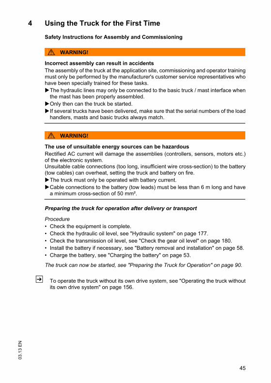
4 Using the Truck for the First Time
Safety Instructions for Assembly and Commissioning
WARNING!
Incorrect assembly can result in accidents
The assembly of the truck at the application site, commissioning and operator trainingmust only be performed by the manufacturer's customer service representatives whohave been specially trained for these tasks.
The hydraulic lines may only be connected to the basic truck / mast interface whenthe mast has been properly assembled.
Only then can the truck be started.
If several trucks have been delivered, make sure that the serial numbers of the loadhandlers, masts and basic trucks always match.
WARNING!
The use of unsuitable energy sources can be hazardous
Rectified AC current will damage the assemblies (controllers, sensors, motors etc.)of the electronic system.Unsuitable cable connections (too long, insufficient wire cross-section) to the battery(tow cables) can overheat, setting the truck and battery on fire.
The truck must only be operated with battery current.
Cable connections to the battery (tow leads) must be less than 6 m long and havea minimum cross-section of 50 mm².
Preparing the truck for operation after delivery or transport
Procedure
• Check the equipment is complete.
• Check the hydraulic oil level, see "Hydraulic system" on page 177.
• Check the transmission oil level, see "Check the gear oil level" on page 180.
• Install the battery if necessary, see "Battery removal and installation" on page 58.
• Charge the battery, see "Charging the battery" on page 53.
The truck can now be started, see "Preparing the Truck for Operation" on page 90.
Z To operate the truck without its own drive system, see "Operating the truck withoutits own drive system" on page 156.

03
.13
EN
46

47
03
.13
EN
D Battery - Servicing, Recharging,
Replacement
1 Safety Regulations Governing the Handling of Lead-Acid Batteries
Maintenance personnel
Batteries may only be charged, serviced or replaced by trained personnel. Thisoperator manual and the manufacturer’s instructions concerning batteries andcharging stations must be observed when carrying out the work.
Fire Protection
Do not smoke and avoid naked flames when handling batteries. Wherever anindustrial truck is parked for charging there must be no inflammable material orconsumables capable of creating sparks within a minimum distance of 2 m from thetruck. The room must be ventilated. Fire protection equipment must be available.
CAUTION!
The use of unsuitable fire protection equipment can result in scalding
Extinguishing fires with water can cause a reaction with the battery acid. This canresult in scalding from the acid.
Use powder extinguishers.
Never extinguish a burning battery with water.
Battery maintenance
The battery cell covers must be kept dry and clean. Terminals and cable shoes mustbe clean, lightly greased with terminal grease and must be securely tightened.Batteries with non insulated terminals must be covered with a non slip insulating mat.
CAUTION!
Before closing the battery panel make sure that the battery cable cannot bedamaged. There is a risk of short circuits with damaged cables.
Battery disposal
Batteries may only be disposed of in accordance with national environmentalprotection regulations or disposal laws. The manufacturer’s disposal instructionsmust be followed.

03
.13
EN
48
49
03
.13
EN
1.1 General notes on handling batteries
WARNING!
Batteries can be hazardous
Batteries contain an acid solution which is poisonous and corrosive. Avoid contactwith battery acid at all times.
Dispose of used battery acid in accordance with regulations.
Always wear protective clothing and goggles when working with batteries.
Do not let battery acid come into contact with skin, clothing or eyes. If necessary,rinse with plenty of clean water.
In the event of physical damage (e.g. skin or eye contact with battery acid) call fora doctor immediately.
Spilled battery acid should be neutralised immediately with plenty of water.
Only batteries with a sealed battery container may be used.
Follow national guidelines and legislation.
WARNING!
Unsuitable batteries that have not been approved for the truck by themanufacturer can be hazardous
The design, weight and dimensions of the battery have a considerable effect on theoperational safety of the truck, in particular its stability and capacity. The use ofunsuitable batteries that have not been approved for the truck by the manufacturercan lead to a deterioration of the braking system during energy recovery operationsand also cause considerable damage to the electrical control system. The use ofbatteries that have not been approved by the manufacturer can therefore affect thehealth and safety of personnel.
Only manufacturer-approved batteries may be used on the truck.
Battery equipment may only be replaced with the agreement of the manufacturer.
When replacing/installing the battery make sure the battery is securely located inthe battery compartment of the truck.
Do not use batteries that have not been approved by the manufacturer.
Park the truck securely before carrying out any work on the batteries (see "Parkingthe truck securely" on page 105).

03
.13
EN
50
2 Battery types
CAUTION!
Always use batteries with insulated covers or live components.
The battery weights are indicated on the battery data plate.
The truck will be equipped with different battery models, depending on theapplication. The following table shows which combinations are included as standard:
Truck model Description Capacity
EFG 213 48V - 4PzS 460 Ah
EFG 215 48V - 4PzS 460 Ah
EFG 216k 48V - 5PzS 575 Ah
EFG 216 48V - 6PzS 690 Ah
EFG 218k 48V - 5PzS 575 Ah
EFG 218 48V - 6PzS 690 Ah
EFG 220 48V - 6PzS 690 Ah
EFG 316k 48V - 5PzS 575 Ah
EFG 316 48V - 6PzS 690 Ah
EFG 318k 48V - 5PzS 575 Ah
EFG 318 48V - 6PzS 690 Ah
EFG 320 48V - 6PzS 690 Ah

51
03
.13
EN
2.1 Battery dimensions
Battery 48 V
Truck model
Dimension (mm) Rated weight
(-5/+8%)in kgL max. W max. H1 +/-
2mmH2 +/- 2mm
EFG 213/215 830 522 612 627 715
EFG 216k/218k/
316k/318k830 630 612 627 855
EFG 216/218/220/
316/318/320830 738 612 627 1025

03
.13
EN
52
3 Exposing the battery
Requirements
– Park the truck securely, see "Parking the truck securely" on page 105.
– Load handler lowered.
– Key switch set to OFF.
– Key removed.
– Set the Emergency Disconnect OFF.
Procedure
• Open the battery door (49) as far as the stop.
• Pull the battery connector (50) and let it drop down from the battery.
The battery is now exposed.
49 50

53
03
.13
EN
4 Charging the battery
WARNING!
The gases produced during charging can cause explosions
The battery produces a mixture of nitrogen and hydrogen (electrolytic gas) duringcharging. Gassing is a chemical process. This gas mixture is highly explosive andmust not be ignited.
Switch the charging station and truck off first before connecting/disconnecting thecharging cable of the battery charging station to/from the battery connector.
The charger must be adapted to the battery in terms of voltage and chargecapacity.
Before charging, check all cables and plug connections for visible signs of damage.
Ventilate the room in which the truck is being charged.
The battery cell surfaces must be exposed during charging to ensure adequateventilation.
Do not smoke and avoid naked flames when handling batteries.
Wherever an industrial truck is parked for charging there shall be no inflammablematerial or lubricants capable of creating sparks within 2 m around the truck.
Fire protection equipment must be on hand.
Do not lay any metallic objects on battery.
It is essential to follow the safety regulations of the battery and charger stationmanufacturers.
4.1 Charging the battery with a stationary charger
Z When charging, the battery door must be exposed by at least 200 mm to provide sufficient ventilation.
Requirements
– Park the truck securely, see "Parking the trucksecurely" on page 105.
– Battery exposed.
– Charger switched off.
– Disconnect the battery connector (50) from thetruck connector (51).
Procedure
• Connect the battery connector (50) to thecharging lead (52)of the stationary charger and turn on the charger.
The battery is now charged.
51
52
50
03
.13
EN
54
4.2 Charging the battery with an on-board charger
NOTE
Improper use of the on-board charger can cause material damage
The on-board charger consisting of a battery charger and battery controller must notbe opened. If faulty, contact the manufacturer’s customer service department.
The charger must only be used for batteries supplied by Jungheinrich or otherapproved batteries provided it has been adapted by the manufacturer's customerservice department.
Batteries must never be swapped from truck to truck.
Do not connect the battery to two chargers simultaneously.
Mains connection
The mains lead may vary depending on the size of the on-board charger.
– On-board charger with 65 Ah: 16 A; 230 V; 3 pin
– On-board charger with 130 Ah: 16 A; 400 V; 5 pin
DANGER!
Risk of electric shock and burning
Damaged and unsuitable wires can cause electric shocks and can overheat, resultingin fires.
Only use mains cables with a maximum length of 30 m.
Fully unreel the cable reel when using it.
Always use original manufacturer’s mains cables.
Insulation safety, acid and caustic ratings must comply with the manufacturer'smains cable.

55
03
.13
EN
Z When charging, the battery door must be exposed by at least 200 mm to provide sufficient ventilation.
Charge the battery
Requirements
– Park the truck securely, see "Parking the truck securely" on page 105.
– Battery exposed.
– Charger switched off.
– Disconnect the battery connector (50) from the truck connector (51).
Procedure
• Connect the on-board charger to the mains socket using the mains cable.
• Charging begins automatically.
• When the truck is switched on the charging status and the residual capacity areshown on the display unit, see "Display" on page 87.
The battery is now charged.
Z If the battery warning indicator (53) lights up after charging the battery, the batterymust be topped up with water when the truck is switched off.
km/h
pmam
100 %
m kg eff code errinch lbs
53

03
.13
EN
56
Battery charger LED displays
Battery controller LED displays
Green LED Meaning
Flashing Charging
Lit Charging complete
Red LED Meaning
Flashing Error
White LED Meaning
Flashing Radio network activated
Blue LED Meaning
LitElectrolyte level too low (measured after each charge)
Yellow LED Meaning
Flashing rolling Charging
Lit Charge status
Red LED Meaning
Flashing Error

57
03
.13
EN
Float charge:
The compensation charge starts automatically when charging is complete.
Partial charging:
The charger is designed to automatically adapt to partially charged batteries. Thiskeeps battery wear to a minimum.
Z If a charging operation has to beinterrupted, press the button (54). Onlyremove the mains connector when thegreen LED goes out.Charging starts again when the mainscable is reconnected to the mainssocket.
54

03
.13
EN
58
5 Battery removal and installation
WARNING!
Accident risk during battery removal and installation
Due to the battery weight and acid there is a risk of trapping or scalding when thebattery is removed and installed.
Note the "Safety regulations for handling acid batteries" section in this chapter.
Wear safety shoes when removing and installing the battery.
Use only batteries with insulated cells and terminal connectors.
Park the truck on a level surface to prevent the battery from sliding out.
Make sure the crane slings have sufficient capacity to replace the battery.
Use only approved battery replacement devices (battery roller stand, replacementtrolley etc.).
Make sure the battery is securely located in the truck's battery compartment.
59
03
.13
EN
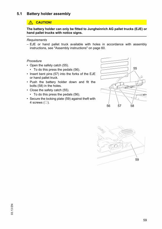
5.1 Battery holder assembly
CAUTION!
The battery holder can only be fitted to Jungheinrich AG pallet trucks (EJE) orhand pallet trucks with notice signs.
Requirements
– EJE or hand pallet truck available with holes in accordance with assemblyinstructions, see "Assembly instructions" on page 60.
Procedure
• Open the safety catch (55).
• To do this press the pedals (56).
• Insert bent pins (57) into the forks of the EJEor hand pallet truck.
• Push the battery holder down and fit thebolts (58) in the holes.
• Close the safety catch (55).
• To do this press the pedals (56).
• Secure the locking plate (59) against theft with4 screws (o).
55
56 57 58
59

03
.13
EN
60
5.1.1 Assembly instructions
Procedure
• Drill 4 holes with a 16 mm diameter into the EJE or hand pallet truck according tothe drill patterns.
• Make sure there is sufficient distance between the connecting rod and the bottomof the forks.
Z Attach safety notices to the EJE.
130
90
16Ø
x4
1150
458
61
03
.13
EN
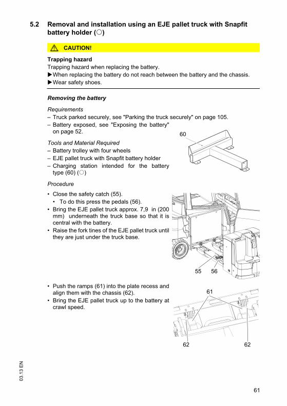
5.2 Removal and installation using an EJE pallet truck with Snapfit
battery holder (o)
CAUTION!
Trapping hazard
Trapping hazard when replacing the battery.
When replacing the battery do not reach between the battery and the chassis.
Wear safety shoes.
Removing the battery
Requirements
– Truck parked securely, see "Parking the truck securely" on page 105.
– Battery exposed, see "Exposing the battery"on page 52.
Tools and Material Required
– Battery trolley with four wheels
– EJE pallet truck with Snapfit battery holder
– Charging station intended for the batterytype (60) (o)
Procedure•
• Close the safety catch (55).
• To do this press the pedals (56).
• Bring the EJE pallet truck approx. 7,9 in (200mm) underneath the truck base so that it iscentral with the battery.
• Raise the fork tines of the EJE pallet truck untilthey are just under the truck base.
•
• Push the ramps (61) into the plate recess andalign them with the chassis (62).
• Bring the EJE pallet truck up to the battery atcrawl speed.
60
55 56
61
62 62
03
.13
EN
62
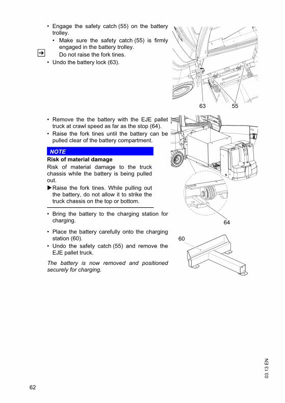
•
• Engage the safety catch (55) on the batterytrolley.
• Make sure the safety catch (55) is firmlyengaged in the battery trolley.
Z Do not raise the fork tines.
• Undo the battery lock (63).
•
• Remove the the battery with the EJE pallettruck at crawl speed as far as the stop (64).
• Raise the fork tines until the battery can bepulled clear of the battery compartment.
NOTE
Risk of material damage
Risk of material damage to the truckchassis while the battery is being pulledout.
Raise the fork tines. While pulling outthe battery, do not allow it to strike thetruck chassis on the top or bottom.
• Bring the battery to the charging station forcharging.
•
• Place the battery carefully onto the chargingstation (60).
• Undo the safety catch (55) and remove theEJE pallet truck.
The battery is now removed and positionedsecurely for charging.
5563
64
60
63
03
.13
EN
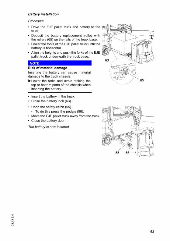
Battery installation
Procedure•
• Drive the EJE pallet truck and battery to thetruck.
• Deposit the battery replacement trolley withthe rollers (65) on the rails of the truck base.
• Lower the forks of the EJE pallet truck until thebattery is horizontal.
• Align the heights and push the forks of the EJEpallet truck underneath the truck base.
NOTE
Risk of material damage
Inserting the battery can cause materialdamage to the truck chassis.
Lower the forks and avoid striking thetop or bottom parts of the chassis wheninserting the battery.
• Insert the battery in the truck.
• Close the battery lock (63).•
• Undo the safety catch (55).
• To do this press the pedals (56).
• Move the EJE pallet truck away from the truck.
• Close the battery door.
The battery is now inserted.
65
63
55 56

03
.13
EN
64
5.3 Removal and installation using a hand pallet truck with Snapfit
battery holder (o)
CAUTION!
Trapping hazard
Trapping hazard when replacing the battery.
When replacing the battery do not reach between the battery and the chassis.
Wear safety shoes.
Removing the battery
Requirements
– Truck parked securely, see "Parking the truck securely" on page 105.
– Battery exposed, see "Exposing the battery"on page 52.
Tools and Material Required
– Battery trolley with four rollers
– Hand pallet truck with Snapfit battery holder
– Charging station intended for the batterytype (60) (o)
Procedure•
• Close the safety catch (55).
• To do this press the pedals (56).
• Fully lower the hand pallet truck.
• Move the hand pallet truck up to the centre ofthe battery until Snapfit contacts the truckchassis.
•
• Raise the forks of the hand pallet truck until therecess (66) is exposed.
• Move the hand pallet truck into the batterycompartment until the safety catches lock thebattery trolley.
• Make sure both safety catches (55) aresecurely engaged in the batteryreplacement trolley.
60
55
56
66
56

65
03
.13
EN
•
• Open the battery lock (63).
• Raise the hand pallet truck (approx. 20 mm)until the battery can be freely pulled out of thebattery compartment.
NOTE
Risk of material damage
Removing the battery can cause materialdamage to the truck chassis.
Raise the forks and avoid striking thetop or bottom parts of the chassis whenremoving the battery.
• Remove the battery.
• Bring the battery to the charging station for charging.•
• Place the battery carefully onto the chargingstation (60)
The battery is now removed and positionedsecurely for charging.
63
60
03
.13
EN
66
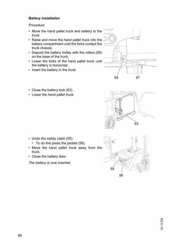
Battery installation
Procedure•
• Move the hand pallet truck and battery to thetruck.
• Raise and move the hand pallet truck into thebattery compartment until the forks contact thetruck chassis.
• Deposit the battery trolley with the rollers (65)on the base of the truck.
• Lower the forks of the hand pallet truck untilthe battery is horizontal.
• Insert the battery in the truck.
•
• Close the battery lock (63).
• Lower the hand pallet truck.
•
• Undo the safety catch (55).
• To do this press the pedals (56).
• Move the hand pallet truck away from thetruck.
• Close the battery door.
The battery is now inserted.
65 67
63
55
56
67
03
.13
EN
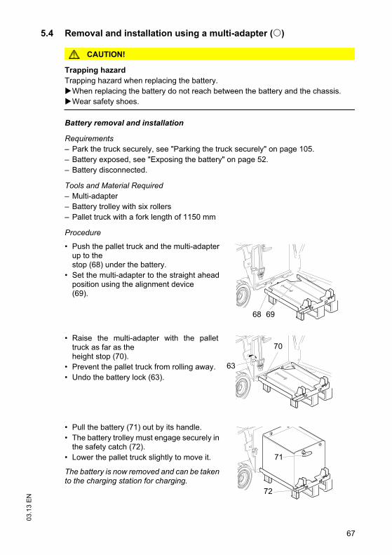
5.4 Removal and installation using a multi-adapter (o)
CAUTION!
Trapping hazard
Trapping hazard when replacing the battery.
When replacing the battery do not reach between the battery and the chassis.
Wear safety shoes.
Battery removal and installation
Requirements
– Park the truck securely, see "Parking the truck securely" on page 105.
– Battery exposed, see "Exposing the battery" on page 52.
– Battery disconnected.
Tools and Material Required
– Multi-adapter
– Battery trolley with six rollers
– Pallet truck with a fork length of 1150 mm
Procedure•
• Push the pallet truck and the multi-adapterup to thestop (68) under the battery.
• Set the multi-adapter to the straight aheadposition using the alignment device(69).
•
• Raise the multi-adapter with the pallettruck as far as theheight stop (70).
• Prevent the pallet truck from rolling away.
• Undo the battery lock (63).
•
• Pull the battery (71) out by its handle.
• The battery trolley must engage securely inthe safety catch (72).
• Lower the pallet truck slightly to move it.
The battery is now removed and can be takento the charging station for charging.
68 69
70
63
71
72

03
.13
EN
68
Z Battery assembly is the reverse order.Release the retaining hook (72) using your foot. Insert the rollers of the batteryreplacement trolley into the battery compartment guides and push the battery intothe battery compartment.
WARNING!
After inserting the battery close the battery lock and then lower the pallet truck.

69
03
.13
EN
5.5 Removal and installation using a worktable for crane loading (o)
CAUTION!
Trapping hazard
Trapping hazard when replacing the battery.
When replacing the battery do not reach between the battery and the chassis.
Wear safety shoes.
Battery removal and installation
Requirements
– Park the truck securely, see "Parking the truck securely" on page 105.
– Battery exposed, see "Exposing the battery" on page 52.
– Battery disconnected.
Tools and Material Required
– Side table
– Battery trolley with six rollers
– Pallet truck with a fork length of 1360 mm
– Crane lifting gear
Procedure•
• Push the hand pallet truck with theworktable as far as thestop (68) underneath thebattery.
•
• Raise the worktable and the pallet truck asfar as the stop (70).
• Undo the battery lock (63).
68
70
63
03
.13
EN
70
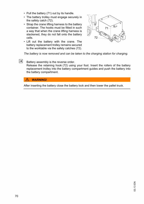
•
• Pull the battery (71) out by its handle.
• The battery trolley must engage securely inthe safety catch (72).
• Strap the crane lifting harness to the batterycontainer. The hooks must be fitted in sucha way that when the crane lifting harness isslackened, they do not fall onto the batterycells.
• Lift out the battery with the crane. Thebattery replacement trolley remains securedto the worktable via the safety catches (72).
The battery is now removed and can be taken to the charging station for charging.
Z Battery assembly is the reverse order.Release the retaining hook (72) using your foot. Insert the rollers of the batteryreplacement trolley into the battery compartment guides and push the battery intothe battery compartment.
WARNING!
After inserting the battery close the battery lock and then lower the pallet truck.
71
72

71
03
.13
EN
5.6 Removal and installation using a fork shoe (o)
CAUTION!
Trapping hazard
Trapping hazard when replacing the battery.
When replacing the battery do not reach between the battery and the chassis.
Wear safety shoes.
Battery removal and installation
Requirements
– Truck parked securely, see "Parking the truck securely" on page 105.
– Battery exposed, see "Exposing the battery"on page 52.
– Battery disconnected.
– Battery lock released.
Tools and Material Required
– Fork shoe
– Second fork lift truck with a capacity to matchthe battery weight. The battery weights areindicated on the battery data plate.
– Battery trolley with two rollers
– Battery with cable guard (73) (o)
– Charging station intended for the battery type (60) (o)
Procedure•
• Place the fork shoe onto the forks of asecond lift truck and secure it to the forkcarriage with a chain (74).
• Tilt the mast forward.
•
• Move the fork shoe up to the stop (75)underneath the battery.
• Raise the fork carriage until the battery isresting on the forks.
60
73
74
75
03
.13
EN
72
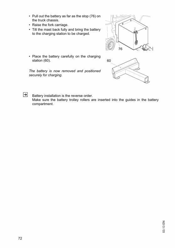
•
• Pull out the battery as far as the stop (76) onthe truck chassis.
• Raise the fork carriage.
• Tilt the mast back fully and bring the batteryto the charging station to be charged.
•
• Place the battery carefully on the chargingstation (60).
The battery is now removed and positionedsecurely for charging.
Z Battery installation is the reverse order.Make sure the battery trolley rollers are inserted into the guides in the batterycompartment.
76
60

73
03
.13
EN
5.7 Removal and installation using a roller conveyor (o)
CAUTION!
Trapping hazard
Trapping hazard when replacing the battery.
When replacing the battery do not reach between the battery and the chassis.
Wear safety shoes.
Battery removal and installation
Requirements
– Park the truck securely, see "Parking the truck securely" on page 105.
– Battery exposed, see "Exposing the battery" on page 52.
– Battery disconnected.
– Battery lock released.
Tools and Material Required
– External roller guided replacement device
Procedure•
Z Note the replacement device manufacturer’sinstructions.
• Bring the external replacement device up tothe truck.
•
• Pull the battery out with the externalreplacement device and transport it to the charging station for charging.
• Deposit the battery securely.
The battery is now removed.
Z Battery assembly is the reverse order.
WARNING!
After inserting the battery close the battery lock.

03
.13
EN
74
5.8 Hook-on battery door removal and installation (o)
CAUTION!
Trapping hazard
Trapping hazard when removing and installing the battery door.
When removing and installing the battery door do not put your hands between thedoor and the chassis.
Wear safety shoes.
Z Only for trucks with a roller conveyor.
Battery door removal
Requirements
– Park the truck securely, see "Parking the truck securely" on page 105.
– Battery disconnected.
Procedure•
• Open the battery door by moving thehandle (77) up.
• Lift the battery door slightly to the outside.
• Pull the battery door up
• Put the battery door down securely.
The battery door is now removed.
Battery door assembly
Requirements
– Park the truck securely, see "Parking the trucksecurely" on page 105.
– Battery disconnected.
Procedure
• Insert the battery door in the receptacles (78).
• Push the battery door onto the truck.
• Push the battery door down and engage it inthe bracket (79).
The battery door is now assembled.
Z If the battery door is not closed correctly, the truck will not be released for travel.Information message (1918) is displayed.
77
78 79
75
03
.13
EN
E Operation
1 Safety Regulations for the Operation of theForklift Truck
Driver authorisation
The truck may only be used by suitably trained personnel, who have demonstrated tothe proprietor or his representative that they can drive and handle loads and havebeen authorised to operate the truck by the proprietor or his representative.
Operator’s rights, obligations and responsibilities
The operator must be informed of his duties and responsibilities and be instructed inthe operation of the truck and shall be familiar with the operating instructions.
Unauthorised use of truck
The operator is responsible for the truck during the time it is in use. The operator mustprevent unauthorised persons from driving or operating the truck. Do not carrypassengers or lift other people.
Damage and faults
The supervisor must be informed immediately of any damage or faults to the truck orattachment. Trucks which are unsafe for operation (e.g. wheel or brake problems)must not be used until they have been rectified.
Repairs
The operator must not carry out any repairs or alterations to the truck withoutauthorisation and the necessary training to do so. The operator must never disable oradjust safety mechanisms or switches.
03
.13
EN
76
Hazardous area
WARNING!
Risk of accidents/injury in the hazardous area of the truck
A hazardous area is defined as the area in which people are at risk due to travel orlifting operations of the truck, its load handler or the load. This also includes the areawithin reach of falling loads or lowering/falling operating equipment.
Instruct unauthorised persons to leave the hazardous area.
In case of danger to third parties, give a warning signal in good time.
If unauthorised persons are still within the hazardous area, stop the truckimmediately.
WARNING!
Falling objects can cause accidents
Falling objects can injure the operator while the truck is being operated.
The operator must remain within the protected area of the overhead guard whilethe truck is being operated.
Safety devices, warning signs and warning instructions
Safety devices, warning signs (see "Indication Points" on page 34) and warninginstructions in the present operating instructions must be strictly observed.
CAUTION!
Reduced headroom can cause injuries
Trucks with reduced headroom are equipped with a warning label within theoperator's line of sight.
The max. recommended body size indicated on this warning sign must beobserved.
The headroom is also reduced when you wear a protective helmet.
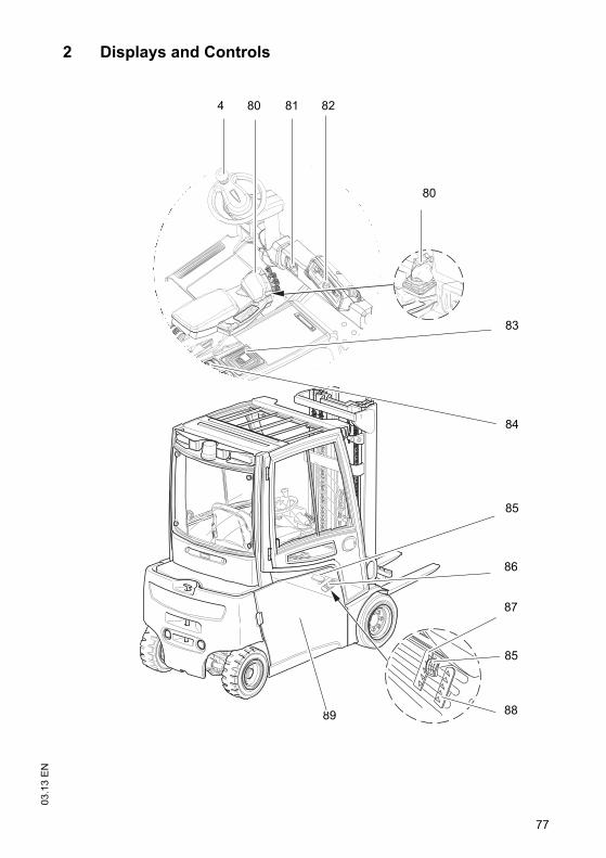
77
03
.13
EN
2 Displays and Controls
4 80 81 82
80
85
86
87
85
88
84
83
89

03
.13
EN
78
Z *If the truck is equipped with an ISM access module refer to the “ISM AccessModule” operator manual.
Item Control / display
Function
4 Steering wheel t Steering the industrial truck.
80 Solo-Pilot t Controls the following functions:
– Fwd/rev. travel direction
– Load handler lift / lower
– Mast forward / reverse tilt
– "Horn" button
– Sideshifter left / right (o)
– Auxiliary hydraulics (o)
Multi-Pilot o
81 Key switch t Switches control current on and off. Removing the key prevents the truck from being switched on by unauthorized personnel.
ISM Access Module o Switches the truck on.
Code lock
82 Dashboard control panel t Displays the battery capacity, service hours, errors, key warning indicators, wheel position and travel direction.
83 Emergency Disconnect switch
Switches power supply on and off.
84 Armrest / side pocket control panel
t Switches electric options on and off
85 Brake pedal t Provides infinitely variable braking control.
86 Accelerator pedal t Provides infinitely variable travel speed control
87 Twin pedal control“Reverse” accelerator pedal
o The truck travels forward when the accelerator pedal is applied.Provides infinitely variable travel speed.
88 Twin pedal control“Forward” accelerator pedal
o The truck reverses when the accelerator pedal is applied.Provides infinitely variable travel speed.
89 On-board charger o Charges the truck

79
03
.13
EN
4 80 81 82
80
85
86
87
85
88
84
83
89

03
.13
EN
80
Item Control / display
Function
90 Travel direction switch(not available with dual pedal control)
t Selects travel direction / neutral position.
91 Lever t Lever for operating the hydraulic functions.
92 "Horn" button t Activates an audible warning.
93 Additional hydraulic function release button
o Activates the additional hydraulic functions or hydraulics that require acknowledgement.
94 Button o Hydraulic auxiliary function control button.
91 9290
93
9190 92
92
90
94
9392
90
91

81
03
.13
EN
2.1 Control panel with display unit
The control panel display unit shows the operating data, the battery charge, theservice hours and error details and information. Pictograms in the left top section ofthe dashboard control panel act as warning indicators.
Item Control /display
Function
95 Parking brake display t Comfort feature, displayed when the parking brake indicator (95) lights up.
Truck prevented from rolling away but not parked securely.
Parking brake is automatically activated after a set time (1 - 60 sec) when the truck stops.The parking brake is automatically released when the accelerator pedal is applied.
96 WARNING t WARNING
– Flashes for faults, an audible warning sounds.
– Flashes when battery capacity is less than 10 %
53 Battery warning indicator
t Not used
km/h
pmam
100 %
m kg eff code errinch lbs
95 96 53 97 98 99 100 101 102
104 105 106 107 108 109 110
103
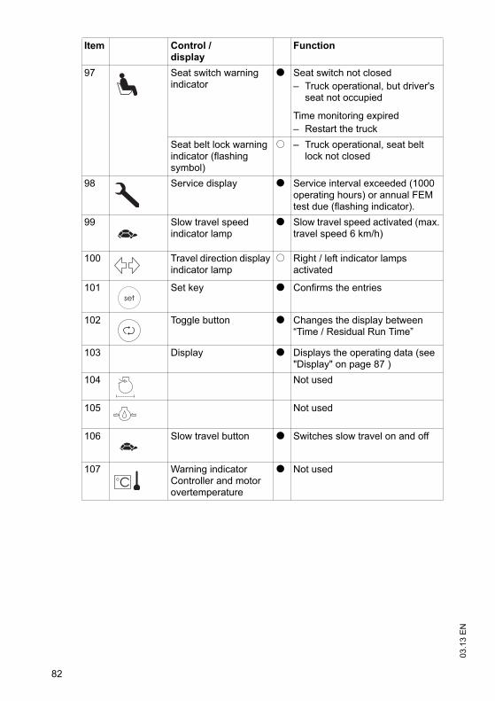
03
.13
EN
82
97 Seat switch warning indicator
t Seat switch not closed
– Truck operational, but driver's seat not occupied
Time monitoring expired
– Restart the truck
Seat belt lock warning indicator (flashing symbol)
o – Truck operational, seat belt lock not closed
98 Service display t Service interval exceeded (1000 operating hours) or annual FEM test due (flashing indicator).
99 Slow travel speed indicator lamp
t Slow travel speed activated (max. travel speed 6 km/h)
100 Travel direction display indicator lamp
o Right / left indicator lamps activated
101 Set key t Confirms the entries
102 Toggle button t Changes the display between “Time / Residual Run Time”
103 Display t Displays the operating data (see "Display" on page 87 )
104 Not used
105 Not used
106 Slow travel button t Switches slow travel on and off
107 Warning indicator Controller and motor overtemperature
t Not used
Item Control /display
Function

83
03
.13
EN
108
95
Yellow LEDs under the parking brake button and
t Secure parking of truck.
The parking brake is activated when the truck is switched on or when the parking brake button (108) is pressed. Yellow LEDs under the parking brake button (108) and the parking brake indicator (95) light up simultaneously.Travel is not enabled when the accelerator pedal is pressed.Travel is enabled by pressing the parking brake button (108).
Parking brake indicator
light up simultaneously
t
109 Program selector t Selects the operating program (moves down a level in the operating program list.)
110 Program selector t Selects the operating program (moves up a level in the operating program list.)
Item Control /display
Function
km/h
pmam
100 %
m kg eff code errinch lbs
95 96 53 97 98 99 100 101 102
104 105 106 107 108 109 110
103

03
.13
EN
84
Z *Five operating programs with different performance levels are available to adaptthe travel and operating functions to the application at hand. Starting from operatingprogram 1 (limited acceleration and speed together with sensitive application of theoperating functions), the performance levels increase to program 5 (maximumperformance for high throughput levels). If necessary the operating programs canalso be adapted or restricted to suit the customer. Contact the manufacturer'scustomer service department.

85
03
.13
EN
2.2 Armrest control panel switch (o)
Function
Work lights
Front windscreen wipers
– Press 1x > intermittent,
– 2x > fast,
– 3x > off
– Hold down on the button > Switch on the windscreen washing system
Rear windscreen wiper
– Press 1x > intermittent,
– 2x > fast,
– 3x > off
– Hold down on the button > Switch on the windscreen washing system
Sideshift centre position
Lift cutout override

03
.13
EN
86
2.3 Side compartment control panel switch (o)
Function
Rear window heating
Beacon
Truck lighting
Parking light
Warning indicator
Lift cutout override
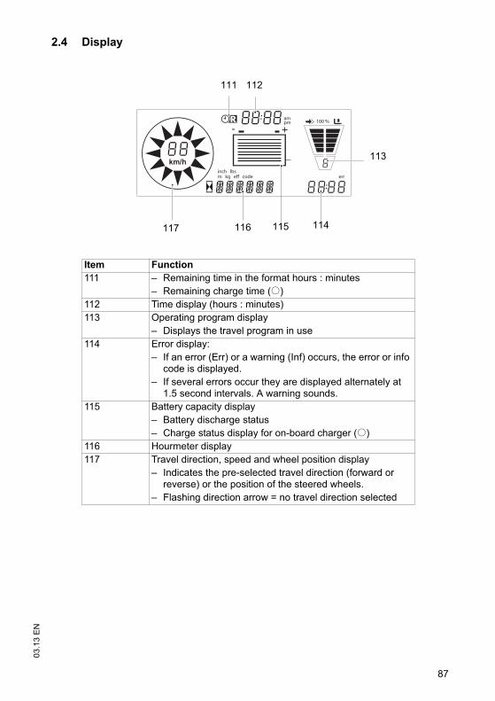
87
03
.13
EN
2.4 Display
Item Function
111 – Remaining time in the format hours : minutes
– Remaining charge time (o)
112 Time display (hours : minutes)
113 Operating program display
– Displays the travel program in use
114 Error display:
– If an error (Err) or a warning (Inf) occurs, the error or info code is displayed.
– If several errors occur they are displayed alternately at1.5 second intervals. A warning sounds.
115 Battery capacity display
– Battery discharge status
– Charge status display for on-board charger (o)
116 Hourmeter display
117 Travel direction, speed and wheel position display
– Indicates the pre-selected travel direction (forward or reverse) or the position of the steered wheels.
– Flashing direction arrow = no travel direction selected
km/h
pmam
100 %
m kg eff code errinch lbs
111 112
113
117 116 115 114

03
.13
EN
88
2.4.1 Battery discharge indicator
NOTE
Full discharge can damage the battery
The standard setting for the battery discharge indicator is based on standardbatteries. When using maintenance-free batteries (gel batteries), the display must bereset.
This adjustment should only be made by the manufacturer’s customer servicedepartment.
The battery discharge indicator shows the battery’s residual capacity.
Charge the battery, see "Charging the battery" on page 53.
The battery charge status is shown on the truck display via a battery symbol (115).When a battery is discharged to the permissible discharge level, the battery symbol(115) is displayed empty.
2.4.2 Battery discharge monitor
If the residual capacity falls below the required level, lifting is inhibited and the travelspeed is reduced. An message appears in the display. Lifting is only released whenthe battery connected is at least 40% charged.
Z In order to complete the lift cycle, the key switch must be turned off and on again.Lifting is then enabled for 30 to 40 seconds.

89
03
.13
EN
2.4.3 Residual time display
Setting the residual time display
Procedure
• Press the toggle switch (102) for 3 seconds. This toggles the display between thetime and the residual time or the remaining charge time for an on-board charger(o).
• Press the Shift key (102) for 8 seconds until the residual time display menu isshown.
• Press the set key (102) to return to normal operating mode.
The time remaining to reach the residual capacity is displayed.
2.4.4 Hourmeter
The service hours are counted when the truck is switched on and the seat switch isclosed.
km/h
pmam
100 %
m kg eff code errinch lbs
102

03
.13
EN
90
3 Preparing the Truck for Operation
3.1 Checks and operations to be performed before starting daily
operation
WARNING!
Damage and other truck or attachment (optional equipment) defects can resultin accidents.
If damage or other truck or attachment (optional equipment) defects are discoveredduring the following checks, the truck must be taken out of service until it has beenrepaired.
Report any defects immediately to your supervisor.
Mark defective truck and take out of service.
Do not return the industrial truck to service until you have identified and rectified thefault.
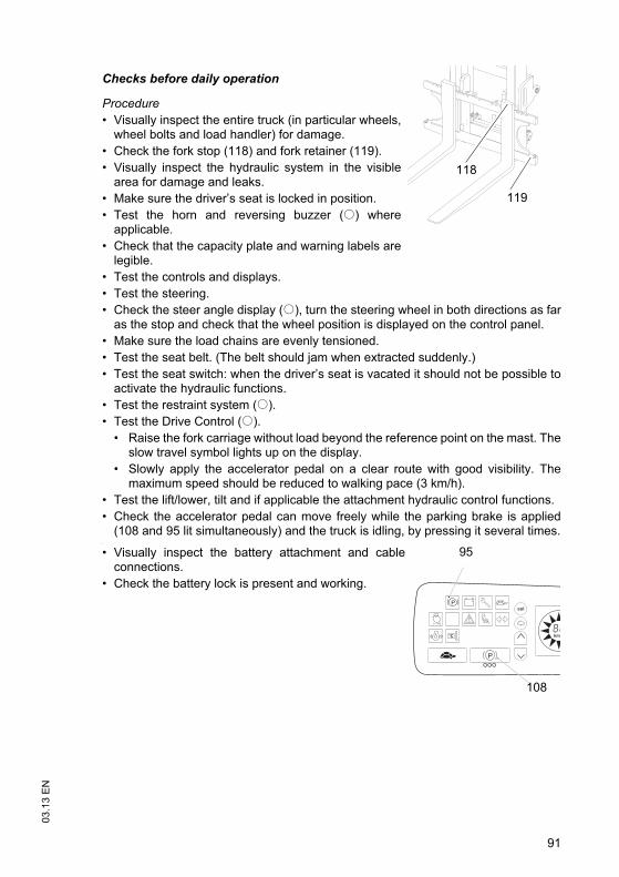
91
03
.13
EN
Checks before daily operation
Procedure
• Visually inspect the entire truck (in particular wheels,wheel bolts and load handler) for damage.
• Check the fork stop (118) and fork retainer (119).
• Visually inspect the hydraulic system in the visiblearea for damage and leaks.
• Make sure the driver’s seat is locked in position.
• Test the horn and reversing buzzer (o) whereapplicable.
• Check that the capacity plate and warning labels arelegible.
• Test the controls and displays.
• Test the steering.
• Check the steer angle display (o), turn the steering wheel in both directions as faras the stop and check that the wheel position is displayed on the control panel.
• Make sure the load chains are evenly tensioned.
• Test the seat belt. (The belt should jam when extracted suddenly.)
• Test the seat switch: when the driver’s seat is vacated it should not be possible toactivate the hydraulic functions.
• Test the restraint system (o).
• Test the Drive Control (o).
• Raise the fork carriage without load beyond the reference point on the mast. Theslow travel symbol lights up on the display.
• Slowly apply the accelerator pedal on a clear route with good visibility. Themaximum speed should be reduced to walking pace (3 km/h).
• Test the lift/lower, tilt and if applicable the attachment hydraulic control functions.
• Check the accelerator pedal can move freely while the parking brake is applied(108 and 95 lit simultaneously) and the truck is idling, by pressing it several times.
•
• Visually inspect the battery attachment and cableconnections.
• Check the battery lock is present and working.
119
118
km/
95
108

03
.13
EN
92
•
• On trucks with lateral battery removal, checkthe left and right stops (64) in the batterycompartment for damage.
• Check the fluid level of the window washersystem, see "Preparing the truck for operation"on page 103.
64

93
03
.13
EN
3.2 Entry and exit
Procedure
• Open the cab door (o).
• To enter and exit the cab, hold onto the handle(120).
Z An additional step is provided for the driver position extension (o).
3.3 Trucks with reduced headroom (o)
WARNING!
An unsuitable workplace can damageyour health
Failure to observe the recommendedbody size can cause stress and endangerthe operator and may lead to lasting illhealth due to an unhealthy posture andexcessive strain on the operator.
The operating company must ensurethat truck operators do not exceed themaximum body size indicated.
The operating company must check thatthe operators can sit in a normal andupright position without having to strain.
120
03
.13
EN
94
3.4 Setting up the operator position
WARNING!
Accidents can occur if the driver's seat, steering column and armrest are notengaged
The driver's seat, steering column and armrest can accidentally adjust during traveland therefore cannot be operated safely.
Do not adjust the driver’s seat, steering column or armrest while travelling.
Procedure
• Before starting to travel, adjust the driver’s seat, steering column and armrest (ifnecessary) so that all the controls are within reach and can be applied withouthaving to strain.
• Adjust the visibility aid equipment (mirrors, camera systems etc.) so that theworking environment can be clearly seen.
3.4.1 Adjusting the driver’s seat
WARNING!
Risk of accidents and damage to health
An incorrectly adjusted driver’s seat can result in accidents and damage to health.
Do not adjust the driver’s seat while travelling.
The driver’s seat should lock in position after adjustment.
Check and adjust the individual driver's seat setting before starting up the truck.
Hold the weight setting lever only by the recess, do not reach through underneaththe lever.
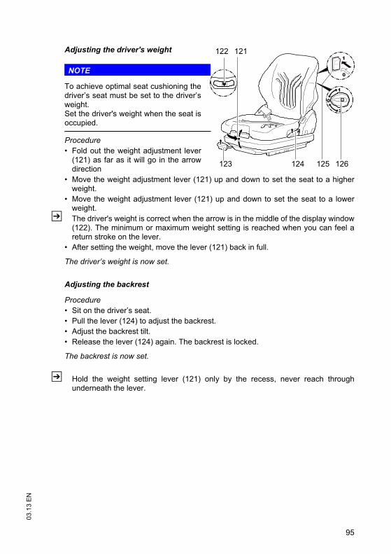
95
03
.13
EN
Adjusting the driver's weight
NOTE
To achieve optimal seat cushioning thedriver’s seat must be set to the driver’sweight.Set the driver's weight when the seat isoccupied.
Procedure
• Fold out the weight adjustment lever(121) as far as it will go in the arrowdirection
• Move the weight adjustment lever (121) up and down to set the seat to a higherweight.
• Move the weight adjustment lever (121) up and down to set the seat to a lowerweight.
Z The driver's weight is correct when the arrow is in the middle of the display window(122). The minimum or maximum weight setting is reached when you can feel areturn stroke on the lever.
• After setting the weight, move the lever (121) back in full.
The driver’s weight is now set.
Adjusting the backrest
Procedure
• Sit on the driver’s seat.
• Pull the lever (124) to adjust the backrest.
• Adjust the backrest tilt.
• Release the lever (124) again. The backrest is locked.
The backrest is now set.
Z Hold the weight setting lever (121) only by the recess, never reach throughunderneath the lever.
121
124123
122
125 126
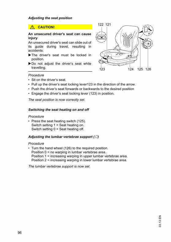
03
.13
EN
96
Adjusting the seat position
CAUTION!
An unsecured driver's seat can causeinjury
An unsecured driver's seat can slide out ofits guide during travel, resulting inaccidents.
The driver's seat must be locked inposition.
Do not adjust the driver’s seat whiletravelling.
Procedure
• Sit on the driver’s seat.
• Pull up the driver’s seat locking lever123 in the direction of the arrow.
• Push the driver’s seat forwards or backwards to the desired position
• Engage the driver’s seat locking lever (123) in position.
The seat position is now correctly set.
Switching the seat heating on and off
Procedure
• Press the seat heating switch (125).Switch setting 1 = Seat heating on.Switch setting 0 = Seat heating off.
Adjusting the lumbar vertebrae support (o)
Procedure
• Turn the hand wheel (126) to the required position.Position 0 = no warping in lumbar vertebrae area.Position 1 = increasing warping in upper lumbar vertebrae area.Position 2 = increasing warping in lower lumbar vertebrae area.
The lumbar vertebrae support is now set.
121
124123
122
125 126

97
03
.13
EN
3.4.2 Adjusting the steering column
Adjusting the steering column
Procedure
• Release the steering column stop (127).
• Set the steering column to the required position (height and angle).
• Fix the steering column stop (127) in position.
The steering column is now positioned.
3.4.3 Adjusting the arm rest
Adjusting the arm rest
Procedure
• Pull up the lock (129) and hold it in this position.
• Move the armrest (128) vertically and horizontally.
• Release the lock (129) at the desired position.
• Push the armrest slightly forward or back until it locks in position.
The armrest is now positioned.
127
128 129

03
.13
EN
98
3.5 Seat Belt
WARNING!
Travelling without a seat belt increases the risk of injury.
Accidents or personal injury can result if the seat belt is not worn or is modified.
Always put the seat belt on before starting the industrial truck.
Do not modify the seat belt.
Damaged or non-operational seat belts must be replaced by trained personnel.
Seat belts must always be replaced after an accident.
Only original spare parts must be used for retrofits or repairs.
Report any defects immediately to your supervisor.
Remove the truck from service until a functional seat belt has been fitted.
Z Protect the seat belt from contamination (e.g. cover it when the truck is idle) andclean it regularly. Frozen belt locks or pulleys must be thawed out and dried toprevent them from freezing up again.The temperature of the warm air should not exceed +60 °C!
Starting the industrial truck on steep slopes
The automatic blocking system locks the belt in the retractor when the truck ispositioned on a steep slope. This prevents the belt from being pulled out of theretractor.
Z Carefully drive the truck off the slope and then put on the belt.

99
03
.13
EN
DANGER!
A faulty seat belt can cause injury
Using a faulty seat belt can result in injury.
Only operate the truck with the seat belt intact. A faulty seat belt should be replacedimmediately.
The truck must remain decommissioned until a functional seat belt has been fitted.
Checking the seat belt
Procedure
• Check the attachment points for wear and damage.
• Check the cover for damage.
• Pull the belt out fully from the retractor and check for damage (loose seams, frayingand nicks).
• Test the belt buckle and make sure the belt returns correctly into the retractor.
Check the automatic locking system
Procedure
• Park the truck on a level surface.
• Jerk the seat belt out suddenly.
Z The locking system should prevent the belt from coming out.
The seat belt has now been checked.

03
.13
EN
100
4 Industrial Truck Operation
4.1 Safety regulations for truck operation
WARNING!
Electromagnetic influence can result in accidents
Strong magnets can cause electronic components such as Hall sensors to becomedamaged, resulting in accidents.
Do not use magnets in the operating area of the truck. Exceptions to this rule arecommercial, weak clamping magnets for attaching notices.
Travel routes and work areas
Only use lanes and routes specifically designated for truck traffic. Unauthorised thirdparties must stay away from work areas. Loads must only be stored in placesspecially designated for this purpose.The truck must only be operated in work areas with sufficient lighting to avoid dangerto personnel and materials. Additional equipment is necessary to operate the truck inareas of insufficient lighting.
DANGER!
Do not exceed the permissible surface and point loading on the travel lanes.At blind spots get a second person to assist.The driver must ensure that the loading dock /dock leveller cannot be removed orcome loose during loading/unloading.
NOTE
Loads must not be deposited on travel or escape routes, in front of safetymechanisms or operating equipment that must be accessible at all times.
Travel conduct
The operator must adapt the travel speed to local conditions. The truck must bedriven at slow speed when negotiating bends or narrow passageways, when passingthrough swing doors and at blind spots. The operator must always observe anadequate braking distance between the forklift truck and the vehicle in front and mustbe in control of the truck at all times. Abrupt stopping (except in emergencies), rapidU turns and overtaking at dangerous or blind spots are not permitted. Do not lean outor reach beyond the working and operating area.
Do not use a mobile phone or walkie-talkie without a handsfree device whileoperating the truck.

101
03
.13
EN
Hazardous situations
If the truck is about to tip over, do not loosen the seat belt. The operator must not jumpoff the truck. The operator must lean his upper body over the steering wheel and holdon with both hands. Tilt your body in the opposite direction of fall.
Travel visibility
The operator must look in the direction of travel and must always have a clear viewof the route ahead. If the truck is carrying loads that affect visibility, the truck musttravel against the load direction. If this is not possible, a second person must walkalongside the truck as a lookout to observe the travel route while maintaining eyecontact with the operator. Proceed only at walking pace and with particular care. Stopthe truck as soon as you lose eye contact.
Negotiating slopes and inclines
Negotiating slopes and inclines up to 15% is only permitted if they are specificallydesigned as travel routes, are clean and have a non-slip surface and providing theycan be safely travelled along in accordance with the truck's technical specifications.The truck must always be driven with the load facing uphill. The industrial truck mustnot be turned, operated at an angle or parked on inclines and slopes. Inclines mustonly be negotiated at slow speed, with the driver ready to brake at any moment.Particular care is required when travelling near slopes and quay walls.
Negotiating lifts, loading ramps and docks
Lifts may only be negotiated if they have sufficient capacity, are suitable for driving onand authorised for truck traffic by the owner. The driver must satisfy himself of theabove before entering these areas. The truck must enter lifts with the load in front andmust take up a position which does not allow it to come into contact with the walls ofthe lift shaft. Persons riding in the lift with the forklift truck must only enter the lift afterthe truck has come to a rest and must leave the lift before the truck. The driver mustensure that the loading ramp / dock cannot move or come loose during loading /unloading.

03
.13
EN
102
Type of loads to be carried
The operator must make sure that the load is in a satisfactory condition. Loads mustalways be positioned safely and carefully. Use suitable precautions to prevent partsof the load from tipping or falling down. Prevent liquid loads from sloshing out.
Inflammable liquids (e.g. fused metal etc.) may only be transported with suitableauxiliary equipment. Contact the manufacturer's customer service department.
Z For safety instructions on the nature of loads to be carried with attachments,see"Lifting, transporting and depositing loads" on page 116.
Towing trailers
The truck may only be used occasionally to tow trailers, see "Towing trailers" onpage 135
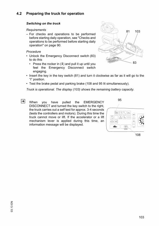
103
03
.13
EN
4.2 Preparing the truck for operation
Switching on the truck
Requirements
– For checks and operations to be performedbefore starting daily operation, see "Checks andoperations to be performed before starting dailyoperation" on page 90.
Procedure
• Unlock the Emergency Disconnect switch (83)to do this
• Press the rocker in (s) and pull it up until youfeel the Emergency Disconnect switchengaging.
• Insert the key in the key switch (81) and turn it clockwise as far as it will go to the“I” position.
• Test the brake pedal and parking brake (108 and 95 lit simultaneously).
Truck is operational. The display (103) shows the remaining battery capacity.
Z When you have pulled the EMERGENCYDISCONNECT and turned the key switch to the right,the truck carries out a self test for approx. 3-4 seconds(tests the controllers and motors). During this time thetruck cannot move or lift. If the accelerator or a liftmechanism lever is applied during this time, aninformation message will be displayed.
83
81 103
km/
95
108
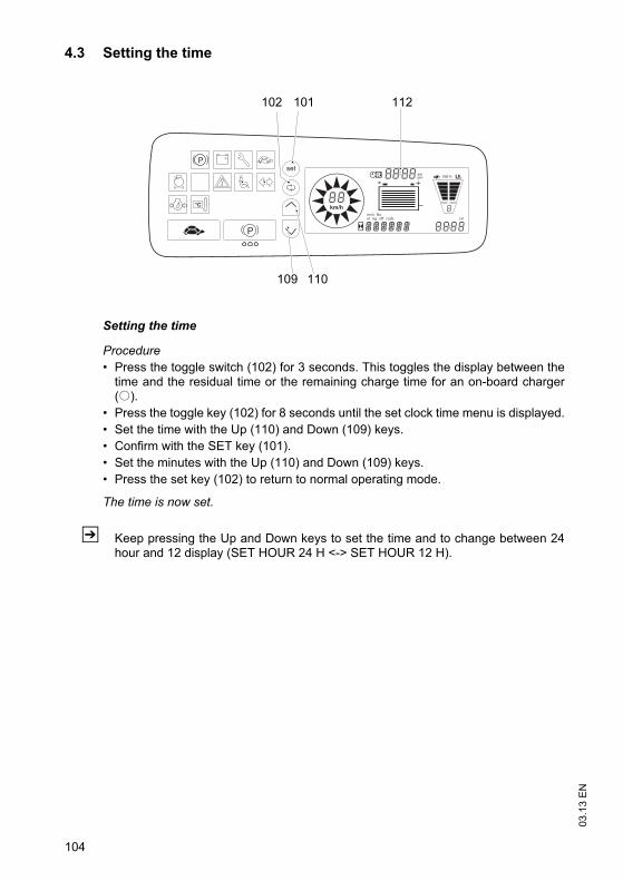
03
.13
EN
104
4.3 Setting the time
Setting the time
Procedure
• Press the toggle switch (102) for 3 seconds. This toggles the display between thetime and the residual time or the remaining charge time for an on-board charger(o).
• Press the toggle key (102) for 8 seconds until the set clock time menu is displayed.
• Set the time with the Up (110) and Down (109) keys.
• Confirm with the SET key (101).
• Set the minutes with the Up (110) and Down (109) keys.
• Press the set key (102) to return to normal operating mode.
The time is now set.
Z Keep pressing the Up and Down keys to set the time and to change between 24hour and 12 display (SET HOUR 24 H <-> SET HOUR 12 H).
km/h
pmam
100 %
m kg eff code errinch lbs
102 101 112
109 110
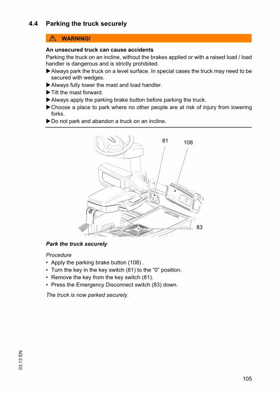
105
03
.13
EN
4.4 Parking the truck securely
WARNING!
An unsecured truck can cause accidents
Parking the truck on an incline, without the brakes applied or with a raised load / loadhandler is dangerous and is strictly prohibited.
Always park the truck on a level surface. In special cases the truck may need to besecured with wedges.
Always fully lower the mast and load handler.
Tilt the mast forward.
Always apply the parking brake button before parking the truck.
Choose a place to park where no other people are at risk of injury from loweringforks.
Do not park and abandon a truck on an incline.
Park the truck securely
Procedure
• Apply the parking brake button (108) .
• Turn the key in the key switch (81) to the “0” position.
• Remove the key from the key switch (81).
• Press the Emergency Disconnect switch (83) down.
The truck is now parked securely.
108
83
81
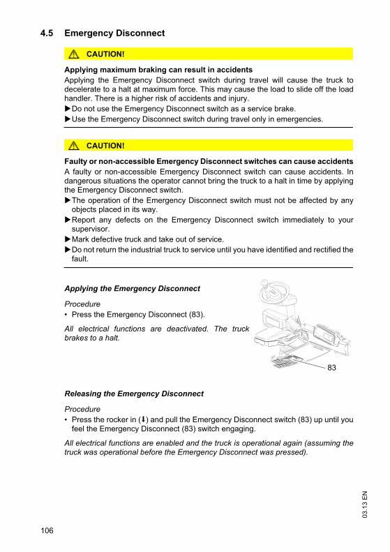
03
.13
EN
106
4.5 Emergency Disconnect
CAUTION!
Applying maximum braking can result in accidents
Applying the Emergency Disconnect switch during travel will cause the truck todecelerate to a halt at maximum force. This may cause the load to slide off the loadhandler. There is a higher risk of accidents and injury.
Do not use the Emergency Disconnect switch as a service brake.
Use the Emergency Disconnect switch during travel only in emergencies.
CAUTION!
Faulty or non-accessible Emergency Disconnect switches can cause accidents
A faulty or non-accessible Emergency Disconnect switch can cause accidents. Indangerous situations the operator cannot bring the truck to a halt in time by applyingthe Emergency Disconnect switch.
The operation of the Emergency Disconnect switch must not be affected by anyobjects placed in its way.
Report any defects on the Emergency Disconnect switch immediately to yoursupervisor.
Mark defective truck and take out of service.
Do not return the industrial truck to service until you have identified and rectified thefault.
Applying the Emergency Disconnect
Procedure
• Press the Emergency Disconnect (83).
All electrical functions are deactivated. The truckbrakes to a halt.
Releasing the Emergency Disconnect
Procedure
• Press the rocker in (s) and pull the Emergency Disconnect switch (83) up until youfeel the Emergency Disconnect (83) switch engaging.
All electrical functions are enabled and the truck is operational again (assuming thetruck was operational before the Emergency Disconnect was pressed).
83

107
03
.13
EN
4.6 Travel
WARNING!
Improper travel can result in accidents
Do not get up from the driver’s seat during travel.
Do not drive the truck unless your are wearing a seat belt and the panels and doorsare properly locked.
Do not lean out of the truck while travelling.
Make sure that the travel area is clear.
Adapt your travel speed to the route conditions in the work area and the load.
Tilt the mast back and raise the fork carriage approx. 200 mm.
Make sure you have sufficient visibility when reversing.
Travel
Requirements
– Truck prepared for operation, see "Preparingthe truck for operation" on page 103.
Procedure
• Release the parking brake, to do this press theparking brake button (108).
• Select the travel directionwith the travel direction switch (90).
• Select the travel speed if necessary, to do thispress the slow travel button (106) or theprogram selector (109/110).
• Raise the load handler approx. 200 mm.
• Tilt the mast back.
• Apply the accelerator pedal (86). The travelspeed is governed by the accelerator (86).
The truck travels in the direction selected.86
90
108106

03
.13
EN
108
Dual pedal (optional equipment)
Requirements
– System prepared for operation, see"Preparing the truck for operation" onpage 103
Procedure
Z For trucks with a dual pedal the traveldirection is selected via the acceleratorpedals (87;88). When the driver leaves thetruck, the truck is automatically set to“Neutral”.
• Press the brake pedal gently to enable traveland operating functions.
• Release the parking brake, to do this pressthe parking brake button (108).
• Raise the load handler approx. 200 mm.
• Tilt the mast back.
• Apply the accelerator pedal (87) to travel forward. The travel speed is governed bythe accelerator (87).
• Apply the accelerator pedal (88) to reverse. The travel speed is governed by theaccelerator (88).
The truck travels in the direction selected.
Changing direction during travel
Procedure
• Set the travel direction switch (90) to the opposite direction while travelling.
The truck decelerates until it starts to travel in the opposite direction.
Z When the truck changes direction it can start travelling at high speed in the oppositedirection unless the accelerator pedal is released in time. Changing directionresults in braking deceleration
88 85 87
109
03
.13
EN
4.7 Steering
Requirements
– Truck ready for operation, see "Preparing the truck for operation" on page 103
Procedure
• To negotiate a right-hand bend:
• Turn the steering wheel clockwise to match the desired steering radius.
• To negotiate a left-hand bend:
• Turn the steering wheel anti-clockwise to match the desired steering radius.
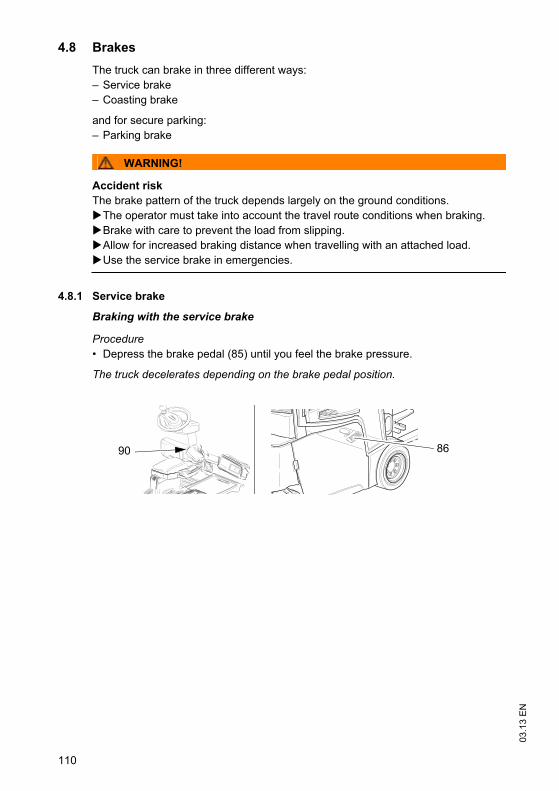
03
.13
EN
110
4.8 Brakes
The truck can brake in three different ways:
– Service brake
– Coasting brake
and for secure parking:
– Parking brake
WARNING!
Accident risk
The brake pattern of the truck depends largely on the ground conditions.
The operator must take into account the travel route conditions when braking.
Brake with care to prevent the load from slipping.
Allow for increased braking distance when travelling with an attached load.
Use the service brake in emergencies.
4.8.1 Service brake
Braking with the service brake
Procedure
• Depress the brake pedal (85) until you feel the brake pressure.
The truck decelerates depending on the brake pedal position.
90 86

111
03
.13
EN
4.8.2 Coasting brake
Braking with the coasting brake
Procedure
• Take your foot off the accelerator pedal (86).
The truck decelerates.
WARNING!
Immediately after the battery has been charged the brake power of the coasting brakemay reduce of their own accord after long periods of application, e.g. ramp operation.
The operator must instruct people to leave the hazardous area.
The operator must perform test braking.
4.8.3 Parking brake
DANGER!
Accident risk
The parking brake will hold the truck with maximum load on a clean ground surface,on inclines of up to 15%.
Do not park and abandon the truck on an incline.
Applying the parking brake during travel will cause the truck to brake to a halt atmaximum force. This may cause the load to slide off the forks. There is a greaterrisk of accidents and injury.

03
.13
EN
112
The parking brake has two functions:
– Truck prevented from rolling away (parking brake automatically activated)When the truck stops the parking brake is automatically activated after a set time(1 - 60 sec), prevents the truck from rolling away and the parking brake indicator(95) lights up. When the accelerator pedal is applied the parking brake isautomatically released and the parking brake indicator (95) goes out. This function of the parking brake prevents the truck from rolling away oninclines up to a maximum of 15%. The truck accelerates when the acceleratorpedal is applied.
– Park the truck securely (parking brake activated by parking brake button(108))Pressing the parking brake button (108) disables travel. The truck is parkedsecurely and the yellow LEDs under the parking brake button (108) light up. Whenthe parking brake button (108) is pressed again the parking brake is released,travel is enabled and the yellow LEDs under the parking brake button (108) go out.This function of the parking brake ensures that the truck is parked securely.The truck will not accelerate when the accelerator pedal is applied.
Z When the truck is switched on the parking brake is activated, travel is enabled andthe yellow LEDs under the parking brake button (108) light up. When the parkingbrake button (108) is pressed the parking brake is released and the yellow LEDsunder the parking brake button (108) go out.
Procedure
• Apply the parking brake button (108) .
Z Yellow LEDs under the parking brake button (108) and the parking brake indicator(95) light up simultaneously.
Z When the yellow LEDs under the parking brake button (108) light up travel is notenabled.
The truck is securely positioned when the yellow LEDs under the parking brakebutton (108) and the parking brake display (95) light up.
km/h
pmam
100 %
m kg eff code errinch lbs
95
108

113
03
.13
EN
The parking brake comfort feature is automatically activated after a set time (1 - 60sec) after the truck stops. The factory setting is 5 sec.The time setting can only be adjusted by the manufacturer’s customer servicedepartment.
Item Control /display
Function
95 Parking brake indicator t Comfort feature, displayed when the parking brake indicator (95) lights up.
Truck prevented from rolling away but not parked securely.
Parking brake is automatically activated after a set time (1 - 60 sec) when the truck stops.The parking brake is automatically released when the accelerator pedal is applied.
108
95
Yellow LEDs under the parking brake button and
t Secure parking of truck.
The parking brake is activated when the truck is switched on or when the parking brake button (108) is pressed. Yellow LEDs under the parking brake button (108) and the parking brake indicator (95) light up simultaneously.Travel is not enabled when the accelerator pedal is pressed.Travel is enabled by pressing the parking brake button (108).
Parking brake indicator
light up simultaneously
t
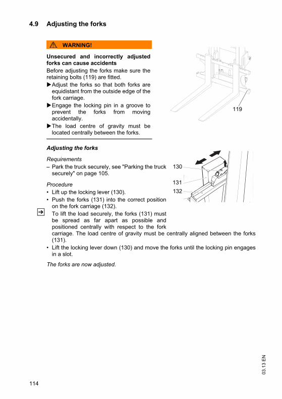
03
.13
EN
114
4.9 Adjusting the forks
WARNING!
Unsecured and incorrectly adjustedforks can cause accidents
Before adjusting the forks make sure theretaining bolts (119) are fitted.
Adjust the forks so that both forks areequidistant from the outside edge of thefork carriage.
Engage the locking pin in a groove toprevent the forks from movingaccidentally.
The load centre of gravity must belocated centrally between the forks.
Adjusting the forks
Requirements
– Park the truck securely, see "Parking the trucksecurely" on page 105.
Procedure
• Lift up the locking lever (130).
• Push the forks (131) into the correct positionon the fork carriage (132).
Z To lift the load securely, the forks (131) mustbe spread as far apart as possible andpositioned centrally with respect to the forkcarriage. The load centre of gravity must be centrally aligned between the forks(131).
• Lift the locking lever down (130) and move the forks until the locking pin engagesin a slot.
The forks are now adjusted.
119
130
131
132

115
03
.13
EN
4.10 Replacing the forks
WARNING!
Unsecured forks can cause injury
You can injure your legs when replacing the forks.
Never pull the forks towards your body.
Always push the forks away from your body.
Secure heavy forks with lifting slings and a crane before pushing them down fromthe fork carriage.
After replacing the forks fit the retaining bolts (119) and make sure the bolts areseated correctly. Retaining bolt torque: 85 Nm.
Replacing the forks
Requirements
– Load handler lowered and forks not touchingthe ground.
Procedure
• Disassemble the retaining bolts (119).
• Loosen the fork stop (118).
• Carefully push the forks off the fork carriage.
The forks are now dismantled from the forkcarriage and can be replaced.
119
118
03
.13
EN
116
4.11 Lifting, transporting and depositing loads
WARNING!
Unsecured and incorrectly positioned loads can cause accidents.
Before lifting a load the operator must make sure that it has been correctly palletisedand does not exceed the truck’s capacity.
Instruct other people to move out of the hazardous area of the truck. Stop workingwith the truck if people do not leave the hazardous area.
Only carry loads that have been correctly secured and positioned. Use suitableprecautions to prevent parts of the load from tipping or falling down.
Do not transport loads other than on the authorised load handler.
Damaged loads must not be transported.
If the stacked load obscures forward visibility, then you must reverse the truck.
Do not exceed the maximum loads specified on the capacity plate.
Check the fork spread before lifting the load and adjust if necessary.
Insert the forks as far as possible underneath the load.
Lifting loads
Requirements
– Load correctly palletised.
– Fork spread for the pallet checked and adjusted if necessary.
– Load weight matches the truck's capacity.
– Forks evenly loaded for heavy loads.
Procedure
• Drive the truck carefully up to the pallet.
• Set the mast vertical.
• Slowly insert the forks into the pallet until the fork shank touches the pallet.
• Raise the load handler.
• Reverse carefully and slowly until the load is outside the storage area. Make sureyou have enough clear space to reverse into.

117
03
.13
EN
NOTE
Loads must not be deposited on travel or escape routes, in front of safetymechanisms or operating equipment that must be accessible at all times.
Transporting loads
Requirements
– Load raised correctly.
– Load handler lowered for transport (approx. 150 - 200 mm above the ground).
– Mast tilted back fully.
Procedure
• Accelerate and decelerate sensitively.
• Adapt your travel speed to the conditions of the route and the load you aretransporting.
• Watch out for other traffic at crossings and passageways.
• Always travel with a lookout at blind spots.
• On slopes and inclines always carry the load facing uphill, never approach at anangle or turn.
Depositing loads
Requirements
– Storage location suitable for storing the load.
Procedure
• Set the mast vertical.
• Drive the truck carefully up to the storage location.
• Carefully lower the load handler so that the forks are clear of the load.
Z Avoid depositing the load to prevent damage to the load and the load handler.
• Lowers the load handler.
• Carefully remove the forks from the pallet.
The load is deposited.

03
.13
EN
118
4.12 Operating the lift mechanism and integrated attachments
WARNING!
Operating the lifting device and integrated attachments can be hazardous
Other people can be injured in the truck's hazardous area.The hazardous area is defined as the area in which people are at risk from the truckmovement, the load handler, attachments etc. This also includes areas which can bereached by falling loads or lowering operating equipment.Apart from the operator (in the normal operating position) there should be no otherpeople in the truck's hazardous area.
Instruct other people to move out of the hazardous area of the truck. Stop workingwith the truck if people do not leave the hazardous area.
If people do not leave the hazardous area despite the warning, prevent the truckfrom being used by unauthorised people.
Only carry loads that have been correctly secured and positioned. Use suitableprecautions to prevent parts of the load from tipping or falling down.
Do not exceed the maximum loads specified on the capacity plate.
Do not stand underneath a raised load handler.
Do not stand on the load handler.
Do not lift other people on the load handler.
Do not reach through the mast.
The controls should only be operated from the driver’s seat, and never suddenly.
The operator must be trained to handle the lift mechanism and the attachments.

119
03
.13
EN
4.12.1 Operating the lift mechanism with the SOLO PILOT
Lifting and lowering
Requirements
– To prepare the truck for operation, see"Preparing the truck for operation" onpage 103
Procedure
• Pull the Solo-Pilot lever (133) in direction H toraise the load.
• Push the Solo-Pilot lever (133)in direction Sto lower the load.
The load is now raised / lowered.
Z When the limit position for the operation has been reached (there will be a noisefrom the pressure relief valve) release the lever. The lever will revert automaticallyto neutral.
Tilting the mast forward / backward
Requirements
– To prepare the truck for operation, see"Preparing the truck for operation" onpage 103
Procedure
• Pull the Solo-Pilot lever (134) in direction R totilt the mast back.
• Push the Solo-Pilot lever (134) in direction Vto tilt the mast forward.
The mast is now tilted back / forward.
Z When the limit position for the operation has been reached (there will be a noisefrom the pressure relief valve) release the lever. The lever will revert automaticallyto neutral.
S
H
133
R
V
134

03
.13
EN
120
Positioning the integrated sideshift (option)
Requirements
– Truck prepared for operation, see "Preparingthe truck for operation" on page 103.
Procedure
• Pull the SOLO-PILOT lever (135) in directionR to move the load handler to the right (fromthe driver’s viewpoint).
• Push the SOLO-PILOT lever (135) in directionV to move the load handler to the left (from thedriver’s viewpoint).
The sideshifter is now positioned.
Z When the limit position for the operation has been reached (there will be a noisefrom the pressure relief valve) release the lever. The lever will revert automaticallyto neutral.
RV
135

121
03
.13
EN
Positioning the forks with an integrated forkpositioner (option)
CAUTION!
Do not use the fork positioner to clamploads.
Requirements
– Truck prepared for operation, see "Preparingthe truck for operation" on page 103.
Procedure
• Press the toggle switch (136) and at the same time pull the SOLO-PILOT (133) indirection Z: the forks will move towards each other.
• Press the toggle switch (136) and at the same time push the SOLO-PILOT (133) indirection A: the forks will spread apart.
The forks are now positioned.
Synchronising the alignment of the forktines with an integrated fork positioner(optional equipment)
Requirements
– Truck prepared for operation, see "Preparingthe truck for operation" on page 103.
– The fork tines are no longer aligned.
Procedure
• Press the toggle switch (136) and at the sametime push the SOLO-PILOT (133) in directionA and spread the fork tines apart as far asthey will go.
• Press the toggle switch (136) and at the same time pull the SOLO-PILOT (133) indirection Z and bring the fork tines as close to each other as they will go.
The fork tines are now synchronised.
Z When the limit position for the operation has been reached (there will be a noisefrom the pressure relief valve) release the lever. The lever will revert automaticallyto neutral.
A
Z
133
136
A
Z
136
133

03
.13
EN
122
4.12.2 Operating the lift mechanism with the Multi Pilot
Lifting and lowering
Requirements
– To prepare the truck for operation, see"Preparing the truck for operation" onpage 103
Procedure
• Pull the Multi-Pilot (80) in direction H to raisethe load.
• Push the Multi Pilot (80) in direction S to lowerthe load.
The load is now raised / lowered.
Z When the limit position for the operation has been reached (there will be a noisefrom the pressure relief valve) release the lever. The lever will revert automaticallyto neutral.
Tilting the mast forward / backward
Requirements
– Truck prepared for operation, see "Preparingthe truck for operation" on page 103.
Procedure
• Push the Multi-Pilot lever (80) in direction V totilt the mast forward.
• Push the Multi-Pilot lever (80) in direction R totilt the mast back.
The mast is now tilted back / forward.
Z When the limit position for the operation has been reached (there will be a noisefrom the pressure relief valve) release the lever. The lever will revert automaticallyto neutral.
H
S 80
V
R
80

123
03
.13
EN
Positioning the integrated sideshift (option)
Requirements
– Truck prepared for operation, see "Preparingthe truck for operation" on page 103.
Procedure
• Press the button (137) to the left to move theload handler to the left (from the driver'sviewpoint).
• Press the button (137) to the right to move theload handler to the right (from the driver'sviewpoint).
The sideshifter is now positioned.
Z When the limit position for the operation has been reached (there will be a noisefrom the pressure relief valve) release the lever. The lever will revert automaticallyto neutral.
Positioning the forks with an integrated forkpositioner (option)
CAUTION!
Do not use the fork positioner to clamploads.
Requirements
– Truck prepared for operation, see "Preparingthe truck for operation" on page 103.
Procedure
• Press the (138) button while at the same time pressing the (93) button, the forkswill spread apart.
• Pull the (138) button while at the same time pressing the (93) button, the forks willmove together.
The forks are now positioned.
80
137
138
93
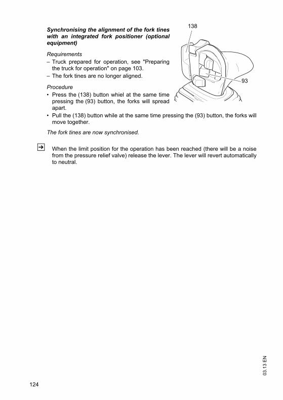
03
.13
EN
124
Synchronising the alignment of the fork tineswith an integrated fork positioner (optionalequipment)
Requirements
– Truck prepared for operation, see "Preparingthe truck for operation" on page 103.
– The fork tines are no longer aligned.
Procedure
• Press the (138) button whiel at the same timepressing the (93) button, the forks will spreadapart.
• Pull the (138) button while at the same time pressing the (93) button, the forks willmove together.
The fork tines are now synchronised.
Z When the limit position for the operation has been reached (there will be a noisefrom the pressure relief valve) release the lever. The lever will revert automaticallyto neutral.
138
93

125
03
.13
EN
4.13 Safety instructions for operating additional attachments
Z Optionally, trucks can be fitted with one or more auxiliary hydraulic functions tooperate attachments. The auxiliary hydraulics are indicated with ZH1, ZH2 andZH3.Auxiliary hydraulic functions for exchangeable equipment are fitted withreplacement couplings on the fork carriage. To fit exchangeable equipment see"Fitting additional attachments" on page 133.
DANGER!
Attaching exchangeable equipment can result in accidents.
Other people can be damaged by attaching exchangeable equipment. Use onlyexchangeable equipment which has been deemed safe after a risk analysis carriedout by the owner.
Only use attachments with a CE mark.
Only use attachments that have been designed by the attachment manufacturer foruse with the respective industrial truck.
Only use attachments that have been fitted for the purpose by the owner.
Make sure the operator has been instructed in the use of the attachment and thathe uses it for its correct purpose.
Re-assess the residual capacity of the truck and if it has been altered, attach anadditional capacity plate to the truck.
Note the attachment manufacturer’s operating instructions.
Only use attachments that do not restrict visibility in the travel direction.
Z If visibility in the travel direction is impaired, the operating company must determineand apply suitable measures to ensure the safe operation of the truck. A lookoutmay have to be used or certain hazardous areas may have to be cordoned off. Thetruck can also be equipped with optional visual aids such as a camera system ormirrors. Travelling with visual aids requires plenty of practice at slow speed.

03
.13
EN
126
Safety instructions for sideshifter and fork positioner attachments
WARNING!
Restricted visibility and reduced tilt resistance can cause accidents
When using sideshifters and fork positioners, the change in centre of gravity canresult in reduced lateral tilt resistance and accidents. Note that this affects visibility aswell.
Adapt the travel speeds to the visibility and load.
Make sure you have sufficient visibility when reversing.
Safety instructions for clamping attachments (e.g. baling clamps, barrel
clamps, grabs etc.)
WARNING!
Falling loads can cause accidents
This can result in malfunctions and the load can fall accidentally.
Clamping attachments may only be added to trucks which have a button to enableadditional hydraulic functions.
Clamping attachments must only be operated on trucks will auxiliary hydraulicsZH1, ZH2 or ZH3.
When connecting the attachment make sure that the hydraulic lines of theattachment are connected to the right ports, see "Fitting additional attachments" onpage 133.
Safety instructions for rotary attachments
WARNING!
A non-centred load centre of gravity can result in accidents
When using rotary devices and non-centred loads, the centre of gravity can bedisplaced from the centre with a high risk of accidents.
Adapt the travel speed to the load.
Lift the load from the centre.

127
03
.13
EN
Safety instructions for telescopic attachments
WARNING!
Accident risk from increased tipover hazard and reduced residual capacity
There is a greater risk of tipover with extended telescopic attachments.
Do not exceed the maximum loads specified on the capacity plate.
Only use the telescopic function for stacking and retrieving.
Retract the telescopic attachment fully during transport.
Adapt the travel speed to changed load centre of gravity.
Safety instructions for attachments when transporting suspended loads
WARNING!
Swinging loads and a reduced residual capacity can result in accidents.
Transporting hanging loads can reduce the stability of the truck.
Adapt the travel speed to the load, less than walking pace.
Secure swinging loads for example with lifting slings.
Reduce the residual capacity and have it certified by a expert.
If the truck is to be operated with hanging loads, proof of sufficient safety distanceunder local operating conditions must be obtained from a specialist assessor.
Safety instructions for using loading buckets as attachments
WARNING!
Increased mast loading can cause accidents.
When carrying out the daily checks and operations before starting, see "Checksand operations to be performed before starting daily operation" on page 90, checkin particular check the fork carriage, mast rails and mast rollers for damage.

03
.13
EN
128
Fork extension safety instructions
WARNING!
Unsecured and oversized fork extensions can cause accidents.
For fork extensions with an open cross sectional area, carry only loads that areresting along the entire length of the fork extension.
Use only fork extensions with the same fork cross section and minimum fork lengthof the truck and which comply with the details on the fork extension data plate.
The basic fork length must be at least 60% of the length of the fork extension.
Lock the fork extensions onto the basic forks.
When carrying out the daily checks and operations before starting, see "Checksand operations to be performed before starting daily operation" on page 90, checkalso the fork extension lock.
Mark any fork extensions with an incomplete or faulty lock and take them out ofservice.
Do not use trucks with an incomplete or faulty fork extension lock. Replace the forkextension.
Only restore the fork extension to service when the fault has been rectified.
Use only fork extensions which are free of dirt and foreign bodies near the entryopening point. Clean the fork extensions as required.

129
03
.13
EN
4.14 Operating additional attachments for the SOLO-PILOT
WARNING!
Incorrect symbols can cause accidents
Symbols on controls that do not depict the function of the attachments can causeaccidents.
Mark the controls with symbols that indicate their function.
Specify the attachments’ direction of movement in accordance with ISO 3691-1 sothat they match the controls’ direction of movement.
4.14.1 Solo Pilot with control of ZH1 hydraulic port
Z Depending on the attachments used thelever (135) is assigned the function of theattachment. Levers that are not required arevoid. For connections see "Fitting additionalattachments" on page 133.
Procedure
• Operating the hydraulic port ZH1:Move the lever (135) in direction V or R.
The attachment’s function is performed.
RV
135

03
.13
EN
130
4.14.2 Solo Pilot with control of ZH1 and ZH2 hydraulic ports
Z Depending on the attachments used the lever/ button (133, 135, 136) is assigned thefunction of the attachment. Unused levershave no function. For connections see "Fittingadditional attachments" on page 133.
Procedure
• Operating the hydraulic port ZH1:Move the lever (135) in direction V or R.
• Operating the hydraulic port ZH2:Press the toggle switch (136) and at the sametime move the lever (133) in the V or Rdirection.
The attachment’s function is performed.
4.14.3 Solo Pilot with control of ZH1, ZH2 and ZH3 hydraulic ports
Z Depending on the attachments used thelevers / buttons (133, 135, 136, 139) areassigned the respective functions. Unusedlevers have no function. For connections see"Fitting additional attachments" on page 133.
Procedure
• Operating the hydraulic port ZH1:Move the lever (135) in direction V or R.
• Operating the hydraulic port ZH2:Move the lever (139) in direction V or R.
• Operating the hydraulic port ZH3:Press the toggle switch (136) and at the sametime move the lever (133) in the V or Rdirection.
The attachment’s function is performed.
R
V
133
136
135
R
V
133
136
139135
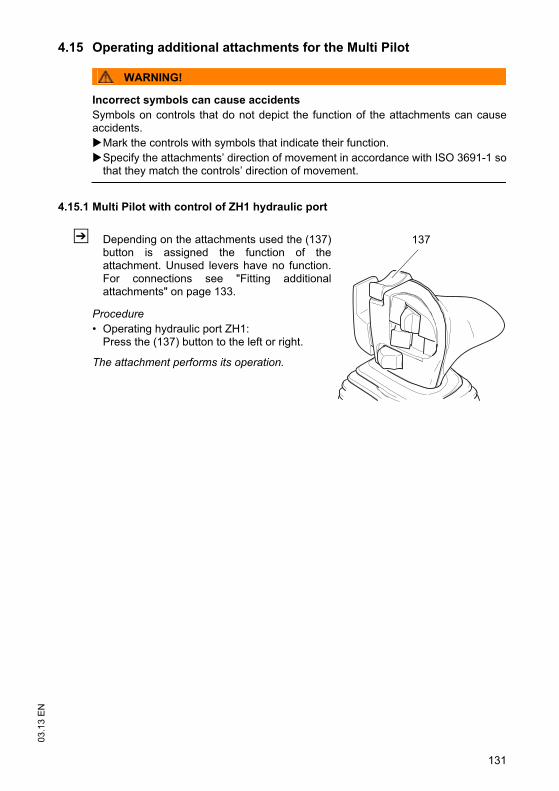
131
03
.13
EN
4.15 Operating additional attachments for the Multi Pilot
WARNING!
Incorrect symbols can cause accidents
Symbols on controls that do not depict the function of the attachments can causeaccidents.
Mark the controls with symbols that indicate their function.
Specify the attachments’ direction of movement in accordance with ISO 3691-1 sothat they match the controls’ direction of movement.
4.15.1 Multi Pilot with control of ZH1 hydraulic port
Z Depending on the attachments used the (137)button is assigned the function of theattachment. Unused levers have no function.For connections see "Fitting additionalattachments" on page 133.
Procedure
• Operating hydraulic port ZH1:Press the (137) button to the left or right.
The attachment performs its operation.
137
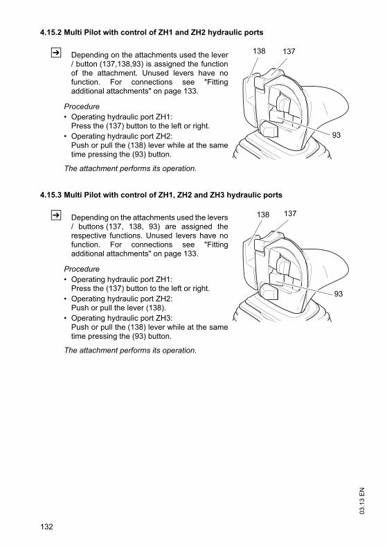
03
.13
EN
132
4.15.2 Multi Pilot with control of ZH1 and ZH2 hydraulic ports
Z Depending on the attachments used the lever/ button (137,138,93) is assigned the functionof the attachment. Unused levers have nofunction. For connections see "Fittingadditional attachments" on page 133.
Procedure
• Operating hydraulic port ZH1:Press the (137) button to the left or right.
• Operating hydraulic port ZH2:Push or pull the (138) lever while at the sametime pressing the (93) button.
The attachment performs its operation.
4.15.3 Multi Pilot with control of ZH1, ZH2 and ZH3 hydraulic ports
Z Depending on the attachments used the levers/ buttons (137, 138, 93) are assigned therespective functions. Unused levers have nofunction. For connections see "Fittingadditional attachments" on page 133.
Procedure
• Operating hydraulic port ZH1:Press the (137) button to the left or right.
• Operating hydraulic port ZH2:Push or pull the lever (138).
• Operating hydraulic port ZH3:Push or pull the (138) lever while at the sametime pressing the (93) button.
The attachment performs its operation.
138
93
137
137
93
138

133
03
.13
EN
4.16 Fitting additional attachments
WARNING!
Incorrectly connected attachments can cause accidents.
Attachments with incorrectly connected hydraulic attachments can result inaccidents.
Attachments must only be assembled and commissioned by trained, specialistpersonnel.
Observe the manufacturer’s operating instructions.
Before starting, check the fasteners are positioned correctly and securely andmake sure they are complete.
Before starting, make sure the attachment is working correctly.
Connecting attachments hydraulically
Requirements
– Non-pressurised hydraulic hoses.
– The exchange ports on the truck are marked ZH1, ZH2 and ZH3.
– Attachment directions of movement defined to match the controls’ direction ofmovement.
Procedure
• Non-pressurised hydraulic hoses
• Switch off the truck and wait a few minutes.
• Attach the plug connector and engage it in position.
• Mark the controls with symbols that indicate their function.
The attachment is now hydraulically connected.
WARNING!
Hydraulic ports for clamping attachments
Clamping attachments may only be added to trucks which have a button to enableadditional hydraulic functions.
On trucks with auxiliary hydraulics ZH2 the clamping function should only beattached to the coupling pair marked ZH2.
On trucks with auxiliary hydraulics ZH3 the clamping function should only beattached to the coupling pair marked ZH3.

03
.13
EN
134
Z Spilled hydraulic oil must be set using a suitable agent and disposed of inaccordance with environmental regulations.If hydraulic oil comes into contact with the skin, wash it off immediately with soapand water. If it comes into contact with the eyes rinse them immediately with flowingwater and call for a doctor.

135
03
.13
EN
5 Towing trailers
DANGER!
Inappropriate speeds and excessive trailer loads can be dangerous
If you do not adapt your speed and / or use an excessive trailer load, the truck canpull apart when cornering and braking.
The truck should only be used occasionally to tow trailers.
The overall weight of the trailer should not exceed the capacity indicated on thecapacity plate, see "Identification points and data plates" on page 34. If a load isalso transported on the load handler, the trailer load must be reduced by the sameamount.
Do not exceed the maximum speed of 5 km/h km/h.
A truck must not be continually operated with trailers.
Do not use supporting loads.
Towing must only be performed on level, secure travel routes.
The owner must test trailer operation with the permissible tow load by means of atrial run under the applicable operating conditions on site.
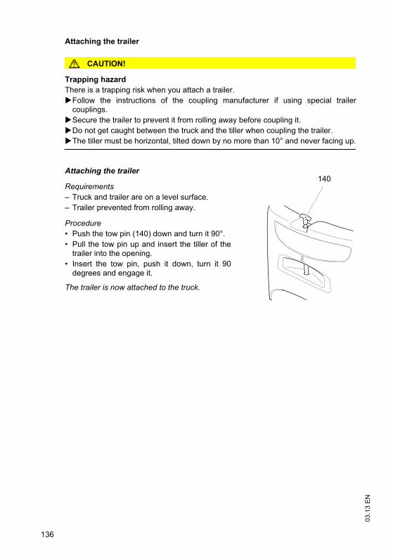
03
.13
EN
136
Attaching the trailer
CAUTION!
Trapping hazard
There is a trapping risk when you attach a trailer.
Follow the instructions of the coupling manufacturer if using special trailercouplings.
Secure the trailer to prevent it from rolling away before coupling it.
Do not get caught between the truck and the tiller when coupling the trailer.
The tiller must be horizontal, tilted down by no more than 10° and never facing up.
Attaching the trailer
Requirements
– Truck and trailer are on a level surface.
– Trailer prevented from rolling away.
Procedure
• Push the tow pin (140) down and turn it 90°.
• Pull the tow pin up and insert the tiller of thetrailer into the opening.
• Insert the tow pin, push it down, turn it 90degrees and engage it.
The trailer is now attached to the truck.
140

137
03
.13
EN
6 Optional equipment
6.1 CanCode keypad
CanCode keypad
The keypad consists of 10 digit keys, a Set key and a okey.
The O key indicates the follow operating statuses via ared / green LED:
– Code lock function (starting up the truck).
– Setting and changing parameters.
6.1.1 Code lock
When the correct code is entered, the truck is ready foruse. You can allocate an individual code to each truck, operator or group of operators.When originally supplied from the factory, the code is indicated on a sticker. Changethe master and operator codes when using the truck for the first time.
Z When the truck is originally supplied, the operator code for the driver’s display andCANCODE (o) is 2-5-8-0.
Commissioning
Procedure
• Enter the code.
When you enter the correct operatorcode the LED (145) turns green. If theLED (145) flashes red this means thewrong code has been entered. Tryagain.
The truck is switched on
Z The Set key (101) has no function in operating mode.
1 2 3
4 5 6
7 8 9
0Set
1 2 3
4 5 6
7 8 9
0Set
141 142 143
144
145
101

03
.13
EN
138
Switching the truck off
Procedure
• Press the O key.
Truck is switched off.
Z The truck can switch off automatically after a set time. To do this the relevant codelock parameters must be entered, see "Parameter Settings" on page 138. Thisadditional safety mechanism in no way discharges the owner from his obligation toprevent the truck from being used by unauthorized parties before leaving the truck.The owner must therefore apply the power-down key each time the truck is left.
6.1.2 Parameter Settings
To change the access code you must enter the master code.
Z The master code factory setting is 7-2-9-5. Change the master code the first timeyou use the truck.
Changing the truck settings
Procedure
• Press the O key (144).
• Enter the master code.
• Enter the three-digit parameter number.
• Confirm with the SET key (101).
• Enter the setting as per parameter list.
Z If the entry is incorrect, the LED (145) of the O key (144) turns red.
• Enter the parameter number again.
• Enter the setting again or change it.
• Confirm with the SET key (101).
• Repeat the procedure for other parameters.
• Then press the O key (144).
The settings are now saved.

139
03
.13
EN
Parameter list
No. Function Setting range Standard setting
Procedure
000 Change master code: The length (4-6 digits) of the master code also determines the length of the operator code (4-6 digits). Provided the operator codes are programmed, only new codes of the same length can be entered. If you wish to change the code length, you must first delete all the operator codes.
0000 - 9999 or
00000 - 99999 or
000000 - 999999
7295 – (LED 141 flashes) Enter current code
– confirm (Set 101)
– (LED 142 flashes)Enter new code
– confirm (Set 101)
– (LED 143 flashes) Repeat new code
– confirm (Set 101)
001 Add code (max. 250) 0000 - 9999 or
00000 - 99999 or
000000 - 999999
2580 – (LED 142 flashes) Code entry
– confirm (Set 101)
– (LED 143 flashes) repeat code entry
– confirm (Set 101)
002 Change code 0000 - 9999 or
00000 - 99999 or
000000 - 999999
– (LED 141 flashes)Enter current code
– confirm (Set 101)
– (LED 142 flashes)Enter new code
– confirm (Set 101)
– (LED 143 flashes)repeat code entry
– confirm (Set 101)
003 Delete code 0000 - 9999 or
00000 - 99999 or
000000 - 999999
– (LED 142 flashes)Enter a new code
– confirm (Set 101)
– (LED 143 flashes) repeat code entry
– confirm (Set 101)
LEDs 141-143 are located in keypads 1-3.
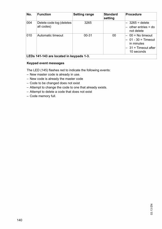
03
.13
EN
140
Keypad event messages
The LED (145) flashes red to indicate the following events:
– New master code is already in use.
– New code is already the master code
– Code to be changed does not exist
– Attempt to change the code to one that already exists.
– Attempt to delete a code that does not exist
– Code memory full.
004 Delete code log (deletes all codes)
3265 – 3265 = delete
– other entries = do not delete
010 Automatic timeout 00-31 00 – 00 = No timeout
– 01 - 30 = Timeout in minutes
– 31 = Timeout after 10 seconds
No. Function Setting range Standard setting
Procedure
LEDs 141-143 are located in keypads 1-3.

141
03
.13
EN
6.2 Assistance systems
The Access, Drive and Lift Control systems help the driver operate the truck withregard to safety regulations, see "Safety regulations for truck operation" on page 100of the present operating instructions.
Travel conduct
The operator must adapt the travel speed to local conditions. The truck must bedriven at slow speed when negotiating bends or narrow passageways, when passingthrough swing doors and at blind spots. The operator must always observe anadequate braking distance between the forklift truck and the vehicle in front and mustbe in control of the truck at all times. Abrupt stopping (except in emergencies), rapidU turns and overtaking at dangerous or blind spots are not permitted. Do not lean outor reach beyond the working and operating area.
6.2.1 Access Control
The truck is only released for operation if:
1)The operator is seated.
2)The truck is switched on via the key switch (ISM o / CanCode o).
3)He is wearing the seat belt.
Z If the driver vacates the seat for a short while, the truck can be operated again whenhe returns (seat occupied) and puts the seat belt back on again, without having toapply the key switch again.
Z If travel is not enabled, the seat switch warning indicator (97) lights up. Items 1 to3 must be performed again in the order listed.
03
.13
EN
142
6.2.2 Drive Control
This option restricts the travel speed of the truck irrespective of the steer angle. Froma factory-set lift height the maximum travel speed is reduced to walking pace (approx.3 km/h) and the slow travel indicator is activated. When the forks fall below this height,the truck accelerates at reduced levels to the speed prescribed by the acceleratorpedal to prevent sudden acceleration when changing from slow travel to normaltravel. Normal acceleration is only activated again when the speed prescribed by theaccelerator pedal has been reached.
Z In addition to the daily checks before starting, see "Checks and operations to beperformed before starting daily operation" on page 90 the driver must carry out thefollowing checks:
– Lift the empty load handler beyond the reference lift height and check if the slowtravel display lights up.
– Steering when the truck is stationary: check if the steering wheel display is working.
6.2.3 Lift Control
This option includes Drive Control and also monitors and controls the mast functions:
Tilt speed reduction as a function of the lift height (from approx. 1,5 m lift height).
– If the load handler is lowered below the limit height, the tilt speed increases up tothe level specified by the control lever.
Optional:
– Tilt angle display.
– Pressing the sideshift centre position switch (see "Side compartment control panelswitch (o)" on page 86) moves the sideshifter automatically to the centre position.
In addition to the daily checks before starting, the driver must carry out thefollowing checks:
Procedure
• Lift the empty load handler beyond the reference lift height and check if the slowtravel display lights up and the tilt speed is clearly reduced.
• Steering at idle: check if the steering wheel display is working.
• Check the tilt angle display by tilting forward and back.

143
03
.13
EN
6.3 Steel cab
For trucks fitted with a steel cabin, both doors can be closed.
CAUTION!
An open door can cause accidents (146)
Do not travel with an open door (146). When opening the door make sure there isnobody in the door’s swing range.
Always close the door tightly and make sure it is locked.
Closing the door does not release the driver from his responsibility to wear a seatbelt, see "Seat Belt" on page 98.
CAUTION!
Cabin doors can pose a trapping hazard
You can trap hands or feet when the cab doors are opened and closed.
Make sure there is nothing between the cab chassis / leg well and the cab doorswhen the doors are opened and closed.
Opening and closing the door
Procedure
• To unlock the cabin door turn the key anti-clockwise.
• To lock the cabin door turn the keyclockwise.
• To open the cabin door, unlock the door andpull out the handle (147).
147
146

03
.13
EN
144
6.4 Sliding windows
CAUTION!
An unlocked sliding window can cause accidents
The sliding windows must be locked at all times.
Opening and closing the windows
Procedure
• Push the lock (149) up.
• Move the window forward or back.
• Insert the lock in the stop (148).
149148
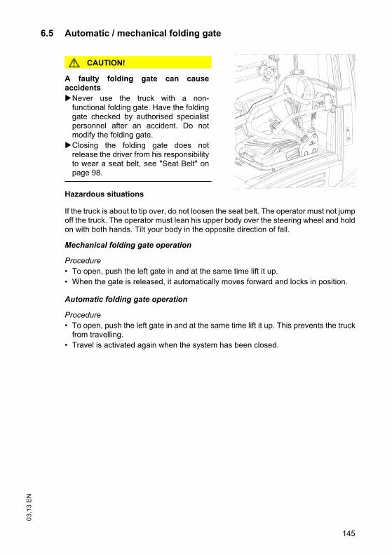
145
03
.13
EN
6.5 Automatic / mechanical folding gate
CAUTION!
A faulty folding gate can causeaccidents
Never use the truck with a non-functional folding gate. Have the foldinggate checked by authorised specialistpersonnel after an accident. Do notmodify the folding gate.
Closing the folding gate does notrelease the driver from his responsibilityto wear a seat belt, see "Seat Belt" onpage 98.
Hazardous situations
If the truck is about to tip over, do not loosen the seat belt. The operator must not jumpoff the truck. The operator must lean his upper body over the steering wheel and holdon with both hands. Tilt your body in the opposite direction of fall.
Mechanical folding gate operation
Procedure
• To open, push the left gate in and at the same time lift it up.
• When the gate is released, it automatically moves forward and locks in position.
Automatic folding gate operation
Procedure
• To open, push the left gate in and at the same time lift it up. This prevents the truckfrom travelling.
• Travel is activated again when the system has been closed.

03
.13
EN
146
6.6 Panel door
CAUTION!
An open door can cause accidents(146)
Do not travel with an open door (146).When opening the door make sure thereis nobody in the door’s swing range.
Always close the door tightly and makesure it is locked.
Closing the door does not release thedriver from his responsibility to wear aseat belt, see "Seat Belt" on page 98.
Requirements
– On trucks with a door monitoring sensor, travelis only enabled when the panel door is closed (o).
Procedure
• Pull the handle (150) towards the operator position, the door swings open.
• Pull the door (146) towards the operator; the door closes.
6.7 Operator position extension
DANGER!
Altering the tilt resistance can be dangerous
The lateral tilt resistance reduces with a higher truck centre of gravity.
The height above the overhead guard (h6) increases by 300 mm, see "Dimensions"on page 22.
Adapt the travel speed of the truck, in particular when cornering.
Z For entry and exit see "Entry and exit" on page 93.
146150

147
03
.13
EN
6.8 Adjusting the driver’s seat
Adjusting the backrest extension
CAUTION!
Accident risk when adjusting the backrest during travel
Do not adjust the backrest extension while travelling.
Procedure
• The backrest extension height can be adjusted by changing the detent.
• Pull the backrest up and lock it in place to extend the backrest.
• Push the backrest down and lock it in place to shorten the backrest.
Adjusting the swivel seat
Procedure
• Pull the locking lever (151) back whilesimultaneously turning the seat to the requiredposition.
• Engage the lock.
The swivel seat is not adjusted and locked inposition.
Z Operate the truck only when the swivel seat islocked in position.
151
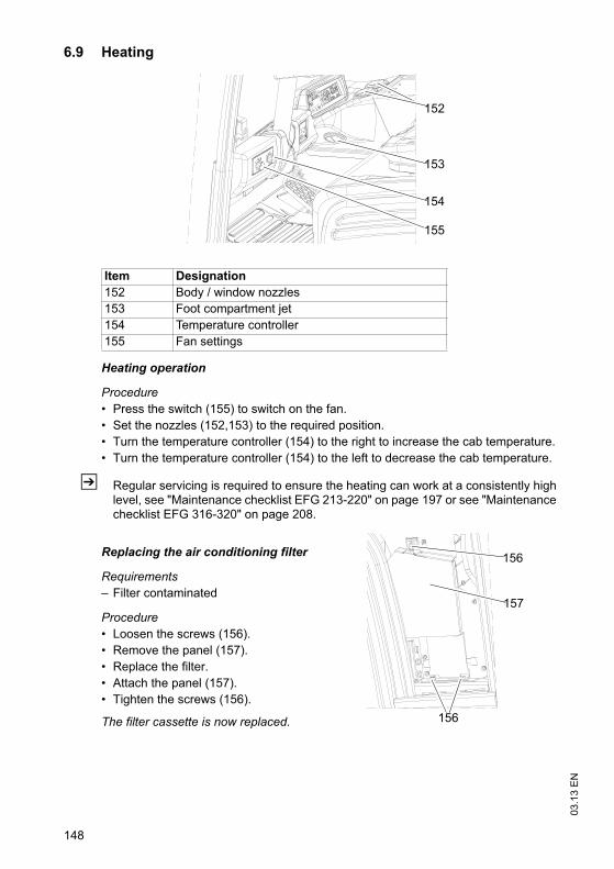
03
.13
EN
148
6.9 Heating
Heating operation
Procedure
• Press the switch (155) to switch on the fan.
• Set the nozzles (152,153) to the required position.
• Turn the temperature controller (154) to the right to increase the cab temperature.
• Turn the temperature controller (154) to the left to decrease the cab temperature.
Z Regular servicing is required to ensure the heating can work at a consistently highlevel, see "Maintenance checklist EFG 213-220" on page 197 or see "Maintenancechecklist EFG 316-320" on page 208.
Replacing the air conditioning filter
Requirements
– Filter contaminated
Procedure
• Loosen the screws (156).
• Remove the panel (157).
• Replace the filter.
• Attach the panel (157).
• Tighten the screws (156).
The filter cassette is now replaced.
Item Designation
152 Body / window nozzles
153 Foot compartment jet
154 Temperature controller
155 Fan settings
152
153
154
155
157
156
156

149
03
.13
EN
6.10 Removable load backrest
CAUTION!
Trapping hazard and heavy load backrest weight
Wear safety gloves and safety shoes when carrying out this operation.
Two people are required to remove and attach the load backrest.
Load backrest disassembly
Procedure
• Loosen the screws (158).
• Remove the load backrest from the forkcarriage and put it down securely.
• Fit the fork retaining screws.
Load backrest assembly
Procedure
• Attach the load backrest to the top rail of the fork carriage.
• Fit the bolts and tighten them with a torque wrench.
Z Torque = 85 Nm
6.11 Lift cutout override
Z A lift cutout device can be factory fitted when working in areas of restricted height.This interrupts lifting.
To continue lifting:
Procedure
• Press the lift cutout override button (see"Side compartment control panel switch (o)"on page 86) .
• Pull the control lever (133).
Lift cutout is deactivated until the button ispressed again or the fork carriage is loweredbelow the height limit setting.
158
S
H
133

03
.13
EN
150
6.12 Fire extinguisher
Procedure
• Open the fasteners (159)
• Pull the fire extinguish out of its bracket
Z To operate, refer to the illustrations onthe fire extinguisher
6.13 Tilt angle display
NOTE
The current tilt angle is shown in anadditional display that is attached on theright of the dashboard.
– The green LED (160) indicates thevertical position to the ground.
159
160

151
03
.13
EN
6.14 Rockinger coupling with hand lever or remote control
Z Refer to the instructions for towing trailers, see "Towing trailers" on page 135.
CAUTION!
Incorrectly coupled trailers can causeaccidents
Make sure the coupling is engagedsecurely before starting the truck.
The contro pin (163) must be flush withthe control sleeve (164).
Rockinger coupling operation (attachingtrailers)
Procedure
• Prevent the trailer from rolling away.
• Adjusting the trailer pull rod to the height of the coupling.
• Pull the hand lever (162) / remote control (161) (o) up.
Z The remote control (161) (o) is located in the overhead guard, depending on thetruck model.
• Slowly reverse the truck until the coupling engages.
• Push the hand lever (162) / remote control (161) (o) down.
Rockinger coupling operation (disconnecting trailers)
Procedure
• Prevent the trailer from rolling away.
• Pull the hand lever (162) / remote control (161) (o) up.
• Drive the truck forward.
• Push the hand lever (162) / remote control (161) (o) down.
162 161
163 164

03
.13
EN
152
6.15 Camera system
CAUTION!
Accident risk from hidden work areas
The camera system acts as an aid to assist safe operation.
Practice travelling and working with the camera system.
Align the camera so that the hidden work area can be seen.
Z When using the camera to reverse, the monitor automatically switches on whenyou engage reverse gear.
Using the camera system
– Press the button (169) on the monitor to switch the camera system on or off.
– Press the button (168) to lighten or darken the screen (day / night settings).
– Press the button (165) to open the menu.
Z Pressing the button several times changes the menu item (contrast, brightness,colour saturation, language, video, light reflection) or quits the menu.
Adjusting the menu items
– Press the button (167) to go one step forward.
– Press the button (166) to go one step back.
Z Clean a dirty screen or vent slots with a soft cloth or brush.
165 166 167 169168
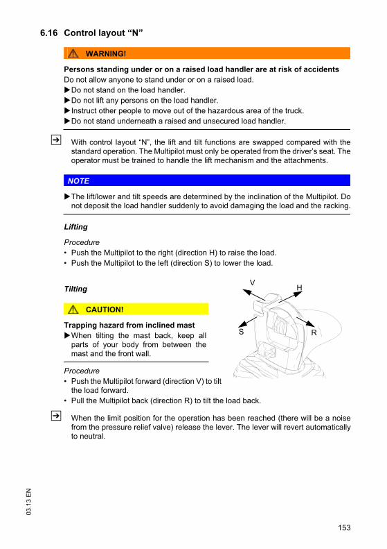
153
03
.13
EN
6.16 Control layout “N”
WARNING!
Persons standing under or on a raised load handler are at risk of accidents
Do not allow anyone to stand under or on a raised load.
Do not stand on the load handler.
Do not lift any persons on the load handler.
Instruct other people to move out of the hazardous area of the truck.
Do not stand underneath a raised and unsecured load handler.
Z With control layout “N”, the lift and tilt functions are swapped compared with thestandard operation. The Multipilot must only be operated from the driver’s seat. Theoperator must be trained to handle the lift mechanism and the attachments.
NOTE
The lift/lower and tilt speeds are determined by the inclination of the Multipilot. Donot deposit the load handler suddenly to avoid damaging the load and the racking.
Lifting
Procedure
• Push the Multipilot to the right (direction H) to raise the load.
• Push the Multipilot to the left (direction S) to lower the load.
Tilting
CAUTION!
Trapping hazard from inclined mast
When tilting the mast back, keep allparts of your body from between themast and the front wall.
Procedure
• Push the Multipilot forward (direction V) to tiltthe load forward.
• Pull the Multipilot back (direction R) to tilt the load back.
Z When the limit position for the operation has been reached (there will be a noisefrom the pressure relief valve) release the lever. The lever will revert automaticallyto neutral.
V
R
H
S

03
.13
EN
154
7 Troubleshooting
7.1 Troubleshooting
This chapter enables the operator to localize and rectify basic faults or the results ofincorrect operation himself. When trying to locate a fault, proceed in the order shownin the remedy table.
Z If, after carrying out the following remedial action, the truck cannot be restored tooperation or if a fault in the electronics system is displayed with a correspondingerror code, contact the manufacturer’s service department.Troubleshooting must only be performed by the manufacturer’s customer servicedepartment. The manufacturer has a service department specially trained for thesetasks.In order for customer services to react quickly and specifically to the fault, thefollowing information is essential:- Truck serial number- Error number on the display unit (if applicable)- Error description- Current location of truck.
Info messages
Display Meaning
1901 Accelerator pedal pressed during power-up
1904 No travel direction selected when accelerator pedal applied
1908Seat switch not closed.Truck operational, but driver’s seat not occupied.
1909 Accelerator pressed while parking brake applied
5915 Truck not operational, battery door open (o)
1917 Accelerator pedal and brake pedal pressed simultaneously
1918 Truck operational but cabin door open (o)
2951 Hydraulic function applied during power-up
5990 Electrolyte level too low (o)
5409 Battery temperature too high (o)
5393 Battery cell faulty (o)

155
03
.13
EN
Fault Possible Cause Action
Truck does not start – Battery connector not plugged in.
– Emergency Disconnect switch pressed.
– Key switch set to O.
– Battery charge too low.
– Battery door open / on-board charger active.
– Faulty fuse.
– Check battery connector and plug in if necessary.
– Unlock the Emergency Disconnect button.
– Set the key switch to “I”.
– Check battery charge, charge battery if necessary.
– Finish charge / close battery door.
– Check the fuses.
Load cannot be lifted – Truck not operational.
– Hydraulic oil level too low.
– Battery discharge monitor has switched off.
– Faulty fuse.
– Load is too heavy.
– Carry out all measures listed under “Truck does not start”.
– Check hydraulic oil level.
– Charge the battery
– Check the fuses (o).
– Note the maximum capacity, see "Data plate" on page 36.
Fault displays – Truck not operational. – Press the EMERGENCY DISCONNECT isolator or turn key switch to 0, after approx. 3 seconds try to perform the desired operation again
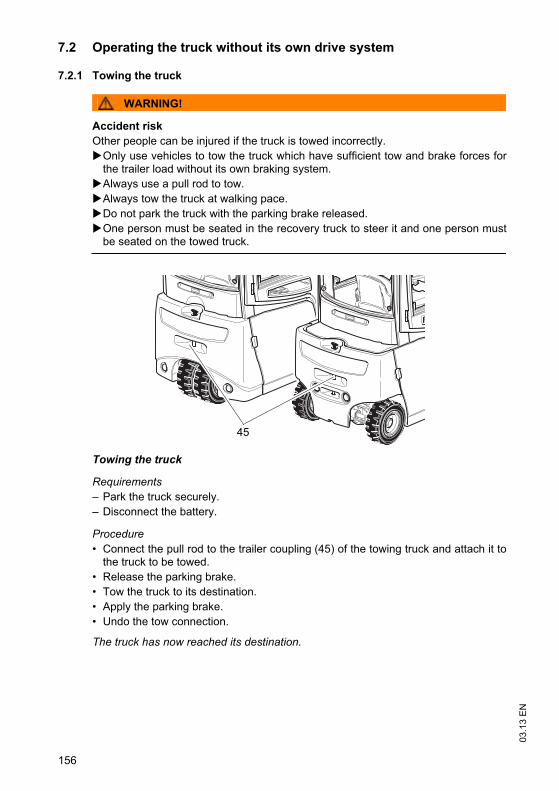
03
.13
EN
156
7.2 Operating the truck without its own drive system
7.2.1 Towing the truck
WARNING!
Accident risk
Other people can be injured if the truck is towed incorrectly.
Only use vehicles to tow the truck which have sufficient tow and brake forces forthe trailer load without its own braking system.
Always use a pull rod to tow.
Always tow the truck at walking pace.
Do not park the truck with the parking brake released.
One person must be seated in the recovery truck to steer it and one person mustbe seated on the towed truck.
Towing the truck
Requirements
– Park the truck securely.
– Disconnect the battery.
Procedure
• Connect the pull rod to the trailer coupling (45) of the towing truck and attach it tothe truck to be towed.
• Release the parking brake.
• Tow the truck to its destination.
• Apply the parking brake.
• Undo the tow connection.
The truck has now reached its destination.
45
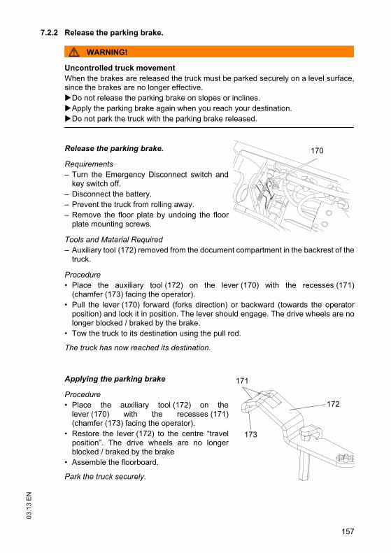
157
03
.13
EN
7.2.2 Release the parking brake.
WARNING!
Uncontrolled truck movement
When the brakes are released the truck must be parked securely on a level surface,since the brakes are no longer effective.
Do not release the parking brake on slopes or inclines.
Apply the parking brake again when you reach your destination.
Do not park the truck with the parking brake released.
Release the parking brake.
Requirements
– Turn the Emergency Disconnect switch andkey switch off.
– Disconnect the battery.
– Prevent the truck from rolling away.
– Remove the floor plate by undoing the floorplate mounting screws.
Tools and Material Required
– Auxiliary tool (172) removed from the document compartment in the backrest of thetruck.
Procedure
• Place the auxiliary tool (172) on the lever (170) with the recesses (171)(chamfer (173) facing the operator).
• Pull the lever (170) forward (forks direction) or backward (towards the operatorposition) and lock it in position. The lever should engage. The drive wheels are nolonger blocked / braked by the brake.
• Tow the truck to its destination using the pull rod.
The truck has now reached its destination.
Applying the parking brake
Procedure
• Place the auxiliary tool (172) on thelever (170) with the recesses (171)(chamfer (173) facing the operator).
• Restore the lever (172) to the centre “travelposition”. The drive wheels are no longerblocked / braked by the brake
• Assemble the floorboard.
Park the truck securely.
170
173
172
171

03
.13
EN
158
7.2.3 Steering the truck when the electric/hydraulic steering has failed
Z The truck cannot be steered if the steering hydraulic system or the truck electronicsare damaged.
Steering the truck when the electric/hydraulic steering has failed
Requirements
– Turn the Emergency Disconnect switch and key switch off.
– Disconnect the battery.
– Prevent the truck from rolling away.
– Release the parking brake.
Tools and Material Required
– Auxiliary tool (172) removed from the document compartment in the backrest of thetruck.
Procedure
• Undo the sensor connector above the motor shaft (pull the red unlocking lever) andplace the auxiliary tool (172) on the Allen screw.
• Turn the drive to the required steering position.
• Tow the truck to its destination using the pull rod, see "Towing the truck" onpage 156.
The truck has now reached its destination.
172
159
03
.13
EN
7.3 Emergency lowering
Z The mast can be lowered manually if a fault occurs in the hydraulic system.
WARNING!
Lowering the mast can result in injuries
Instruct other people to move out of the hazardous area of the truck duringemergency lowering.
Never stand underneath a raised load handler.
Only operate the emergency lowering valve when standing next to the truck.
Emergency lowering of the mast cannot be applied when the load handler is in therack.
Report any defects immediately to your supervisor.
Tag out and decommission a faulty lift truck.
Only return the truck to service when you have identified and rectified the fault.
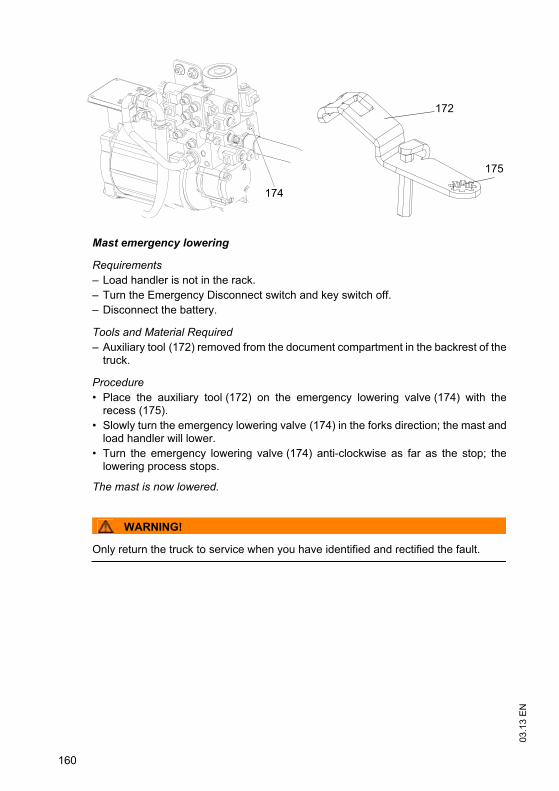
03
.13
EN
160
Mast emergency lowering
Requirements
– Load handler is not in the rack.
– Turn the Emergency Disconnect switch and key switch off.
– Disconnect the battery.
Tools and Material Required
– Auxiliary tool (172) removed from the document compartment in the backrest of thetruck.
Procedure
• Place the auxiliary tool (172) on the emergency lowering valve (174) with therecess (175).
• Slowly turn the emergency lowering valve (174) in the forks direction; the mast andload handler will lower.
• Turn the emergency lowering valve (174) anti-clockwise as far as the stop; thelowering process stops.
The mast is now lowered.
WARNING!
Only return the truck to service when you have identified and rectified the fault.
172
175
174
161
03
.13
EN
F Industrial Truck Maintenance
1 Operational Safety and Environmental Protection
The checks and servicing operations contained in this chapter must be performed inaccordance with the maintenance checklist service intervals.
WARNING!
Risk of accidents and component damage
Any modification to the truck, in particular the safety mechanisms, is prohibited.
Exception: Owners should only make changes or have changes made to poweredindustrial trucks if the truck manufacturer is no longer operating in the field and thereis no successor to the business; owners must however:
– Ensure that the changes to be made are planned, tested and performed by aspecialist engineer in industrial trucks taking safety into account.
– keep permanent graphic records of the plans, tests and completion of the changes
– carry out and have authorised the respective changes to the capacity data plates,decals and stickers as well as the operator and service manuals.
– attach permanent and clearly visible marking to the truck indicating the types ofchanges made, the date of the changes and the name and address of theorganisation responsible for the work.
NOTE
Only original spare parts are subject to the manufacturer's quality control. To ensuresafe and reliable operation, use only the manufacturer's spare parts.
Z On completion of inspection and service work, carry out the operations listed in the“Recommissioning the truck after cleaning or maintenance work” section (see"Restoring the truck to service after maintenance and repairs" on page 190).
03
.13
EN
162
2 Maintenance Safety Regulations
Maintenance and repair personnel
Z The manufacturer has a service department specially trained for these tasks. Amaintenance contract with the manufacturer will ensure trouble-free operation.
Truck maintenance and repair work must only be carried out by specially trainedpersonnel. The following operations are assigned to the following target groups.
Customer Services
Customer Services are specially trained in the use of the truck and are able to carryout maintenance and repairs independently. Customer Services are aware of therelevant standards, guidelines and safety regulations as well as potential risks.
Operating company
The maintenance personal of the operating company has the technical expertise andexperience to perform the activities in the maintenance check list for the operatingcompany. The maintenance and repair work to be performed by the operatingcompany are also written down, see "Industrial Truck Maintenance" on page 161.
163
03
.13
EN
2.1 Consumables and used parts
CAUTION!
Consumables and used parts are an environmental hazard
Used parts and consumables must be disposed of in accordance with the applicableenvironmental protection regulations. To change the oil contact the manufacturer'scustomer service department, who have been specially trained for this task.
Note the safety regulations when handling these materials.
2.2 Wheels
WARNING!
The use of tyres that do not match the manufacturer's specifications can resultin accidents.
The quality of tyres affects the stability and performance of the truck.
Uneven wear affects the truck's stability and increases the stopping distance.
When replacing tyres make sure the truck is not skewed.
Always replace tyres in pairs, i.e. left and right at the same time.
Z When replacing rims and tyres fitted at the factory, only use the manufacturer’soriginal spare parts. Otherwise the manufacturer’s specifications cannot beensured.

03
.13
EN
164
2.3 Lift Chains
WARNING!
Non-lubricated and incorrectly cleaned lift chains can cause accidents
Lift chains are safety-critical parts. They must not contain any serious contamination.Lift chains and pivot pins must always be clean and well lubricated.
Lift chains should only be cleaned with paraffin derivatives e.g. petroleum or dieselfuels.
Do not clean lift chains with high pressure jets or chemical cleaning agents.
Immediately after cleaning, dry the lift chain with compressed air and apply a chainspray.
Always lubricate a chain when it is discharged.
Lubricate a lift chain with particular care around the pulleys.
WARNING!
Diesel fuel can be hazardous
Diesel fuel can cause irritation if it comes into contact with the skin. Rinse anyaffected areas thoroughly.
If it comes into contact with the eyes rinse them immediately with flowing water andcall for a doctor.
Wear safety gloves when handling diesel fuels.

165
03
.13
EN
2.4 Hydraulic system
WARNING!
Brittle hydraulic hose lines can cause accidents
The hoses must be replaced every six years. The manufacturer's customer servicedepartment is specially trained to carry out these operations.
Observe the date of manufacturer on the hydraulic hoses.
WARNING!
Leaky hydraulic systems can result in accidents
Hydraulic oil can escape from leaky and faulty hydraulic systems.
Report any defects immediately to your supervisor.
Mark defective truck and take out of service.
Do not return the industrial truck to service until you have identified and rectified thefault.
Remove any spilled hydraulic immediately with an appropriate bonding agent.
The bonding agent / consumable mixture must be disposed of in accordance withregulations.
WARNING!
Holes or hairline cracks in the hydraulic hoses can cause injury and infection
Pressurised hydraulic oil permeating through fine holes or hairline cracks in thehydraulic hoses can penetrate the skin, causing severe injury.
Call for a doctor immediately if you are injured.
Do not touch pressurised hydraulic hoses.
Report any defects immediately to your supervisor.
Mark defective truck and take out of service.
Do not return the industrial truck to service until you have identified and rectified thefault.
Remove any spilled hydraulic immediately with an appropriate bonding agent.
The bonding agent / consumable mixture must be disposed of in accordance withregulations.

03
.13
EN
166
3 Lubricants and Lubrication Schedule
3.1 Handling consumables safely
Handling consumables
Consumables must always be handled correctly. Follow the manufacturer’sinstructions.
WARNING!
Improper handling is hazardous to health, life and the environment
Consumables can be flammable.
Keep consumables away from hot components and naked flames.
Always keep consumables in prescribed containers.
Always fill consumables in clean containers.
Do not mix up different grades of consumable. The only exception to this is whenmixing is expressly stipulated in the operating instructions.
CAUTION!
Spilled consumables can cause slipping and endanger the environment
Risk of slipping from spilled consumables. The risk is greater when combined withwater.
Do not spill consumables.
Spilled consumables must be removed immediately with an appropriate bondingagent.
The bonding agent / consumable mixture must be disposed of in accordance withregulations.
167
03
.13
EN
WARNING!
Improper handling of oils can be hazardous
Oils (chain spray / hydraulic oil) are flammable and poisonous.
Dispose of used oils in accordance with regulations. Store used oil safely until it canbe disposed of in accordance with regulations.
Do not spill oil.
Spilled oils must be removed immediately with an appropriate bonding agent.
The mixture consisting of the bonding agent and oil must be disposed of inaccordance with regulations.
Observe national regulations when handling oils.
Wear safety gloves when handling oils.
Prevent oil from coming into contact with hot motor parts.
Do not smoke when handling oil.
Avoid contact and digestion. If you swallow oil do not induce vomiting but seekmedical assistance immediately.
Seek fresh air after breathing in oil fumes or vapours.
If oil has come into contact with your skin, rinse your skin with water.
If oil has come into contact with your eyes, rinse them with water and seek medicalassistance immediately.
Replace oil-soaked clothing and shoes immediately.
CAUTION!
Consumables and used parts are an environmental hazard
Used parts and consumables must be disposed of in accordance with the applicableenvironmental protection regulations. To change the oil contact the manufacturer'scustomer service department, who have been specially trained for this task.
Note the safety regulations when handling these materials.
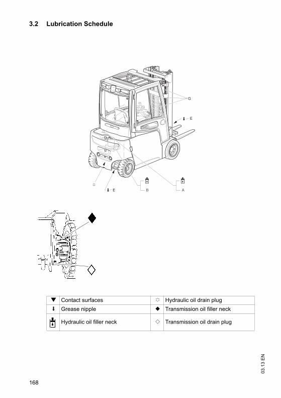
03
.13
EN
168
3.2 Lubrication Schedule
g Contact surfaces c Hydraulic oil drain plug
s Grease nipple b Transmission oil filler neck
Hydraulic oil filler neck a Transmission oil drain plug
B
E
AE
G

169
03
.13
EN
3.3 Consumables
1) Valid for temperatures -5/+30 °C2) Valid for temperatures -20/-5 °C3) Valid for temperatures +30/+50 °C
Code Order no.Packagequantity
Capacity Description Used for
A
51 132 827* 5l
440AH= 18L550AH= 20.5L660AH= 24L
Jungheinrichhydraulic oil
Hydraulicsystem
50 426 072 20l HLPD 32 1)
50 429 647 20l HLPD 22 2)
50 124 051 5l HV 68 3)
51 082 888 5lPlantosyn 46 HVI(BIO hydraulic oil)
B
51 132 827* 5l
2.5 l
Jungheinrichhydraulic oil
Steering(EFG 316-
320)
50 426 072 20l HLPD 32 1)
50 429 647 20l HLPD 22 2)
50 124 051 5l HV 68 3)
51 082 888 5lPlantosyn 46 HVI(BIO hydraulic oil)
E 50 157 382 1kgLubrication
greaseK-L 3N 3)
Steer axle(EFG 316-
320)
G 29 201 280 400ml Chain spray Chains
N 50 468 784 1l 2 x 0.35 lTransmission oil,
ShellSpirax MA 80 W
Gear unit

03
.13
EN
170
Z *The trucks are factory-equipped with a special manufacturer's hydraulic oil (theJungheinrich hydraulic oil with a blue colouration) or the Plantosyn 46 HVI biohydraulic oil. This special hydraulic oil can only be obtained from the manufacturer'scustomer service department. The use of named alternative hydraulic oils is notprohibited but may lead to a decline in functionality. This hydraulic oil may be mixedwith one of the named alternative hydraulic oils.
WARNING!
Industrial trucks are factory-equipped with "HLP D22/32" hydraulic oil or "+ 2%Plantosyn 46 HVI" BIO hydraulic oil.You cannot change from "Plantosyn 46 HVI" BIO hydraulic oil to the manufacturer'shydraulic oil. The same applies to changing from the manufacturer's hydraulic oil to"Plantosyn 46 HVI" bio hydraulic oil. Do not mix the Plantosyn 46 HVI bio hydraulic oil with the manufacturer's hydraulicoil or one of the named alternative hydraulic oils.
Grease guidelines
Code Saponification Dew point°C
Worked penetration at 25 °C
NLG1 class Application temperature°C
E Lithium 185 265 - 295 2 -35/+120

171
03
.13
EN
4 Maintenance and repairs
4.1 Preparing the truck for maintenance and repairs
All necessary safety measures must be taken to avoid accidents when carrying outmaintenance and repairs. The following preparations must be made:
Procedure
• Park the truck securely, see "Parking the truck securely" on page 105.
• Fully lower the load handler.
• Disconnect the battery to prevent the truck from being switched on accidentally.

03
.13
EN
172
4.2 Lifting and jacking up the truck safely
WARNING!
A truck tipover can cause accidents
In order to raise the truck, use only suitable lifting gear at the points specially providedfor this purpose.
Note the weight of the truck on the data plate.
Always use a jack with a minimum capacity of 2500 kg kg.
Raise the unladen truck on a level surface.
When raising the truck, take appropriate measures to prevent it from slipping ortipping over (e.g. wedges, wooden blocks).
Raising and jacking up the truck securely
Requirements
– Prepare the truck for maintenance and repairs (see "Preparing the truck formaintenance and repairs" on page 171).
Tools and Material Required
– Jack
– Hard wooden blocks
Procedure
• Place the jack against the contact point.
Z Jack contact point, see "Identification points and data plates" on page 34.
• Raise the truck.
• Support the truck with hard wooden blocks.
• Remove the jack.
The truck is now securely raised and jacked up.

173
03
.13
EN
4.3 Opening the rear panel
Opening the panel
Requirements
– Prepare the truck for maintenance and repairs (see"Preparing the truck for maintenance and repairs"on page 171).
Procedure
• Undo the two quick release fasteners (176).
• Pull the rear panel back and remove it.
The rear panel is now open. The fuses and otherelectrical components can now be reached.
Closing the panel
Procedure
• Place the rear panel in position.
• Secure two quick release fasteners (176).
The rear panel is now closed.
176

03
.13
EN
174
4.4 Checking the wheel attachments.
WARNING!
Using different tyres can cause accidents
The quality of tyres affects the stability and performance of the truck.
The diameter of the wheels must differ by no more than 15 mm.
Always replace tyres in pairs. After replacing the tyres check the wheel nuts aresecure after 10 service hours.
Always use tyres of the same make, model and profile.
Checking the wheel attachment
Requirements
– Prepare the truck for maintenance and repairs (see"Preparing the truck for maintenance and repairs"on page 171).
Tools and Material Required
– Torque wrench
Procedure
• Torque the wheel nuts (177) crosswise with atorque wrench, for torques see "Tyre type" on page 30.
The wheel attachment is now checked.
Z When using pneumatic tyres check the air pressure, for the air pressure see "Tyretype" on page 30
177

175
03
.13
EN
4.5 Replacing wheels
WARNING!
A truck tipover can cause accidents
In order to raise the truck, use only suitable lifting gear at the points specially providedfor this purpose.
Note the weight of the truck on the data plate.
Always use a jack with a minimum capacity of 2500 kg kg.
Raise the unladen truck on a level surface.
When raising the truck, take appropriate measures to prevent it from slipping ortipping over (e.g. wedges, wooden blocks).
WARNING!
Falling wheels can cause injury
The wheels of the truck are very heavy. A single wheel can weigh up to 150 kg.
Always replace wheels with a suitable tool and protective equipment.
Dismantle the wheels
Requirements
– Prepare the truck for maintenance and repairs(see "Preparing the truck for maintenance andrepairs" on page 171).
Tools and Material Required
– Jack
– Hard wooden blocks
– Mounting lever
– Torque wrench
Procedure
• Place the jack against the contact point.
Z Jack contact point, see "Identification points and data plates" on page 34.
• Raise the truck.
• Support the truck with hard wooden blocks.
• Undo the wheel attachment (177).
• Disassemble the wheel, using a suitable mounting lever if necessary.
The wheel is now disassembled.
177

03
.13
EN
176
Fitting the wheels
Procedure
• Assemble the wheel, using a suitable mountinglever if necessary.
• Fit the wheel attachment.
• Remove the hard wooden blocks.
• Lower the truck.
• Torque the wheel attachment (177) crosswisewith a torque wrench, for torques see "Tyre type"on page 30.
The wheel is now assembled.
Z When using pneumatic tyres check the air pressure, for the air pressure see "Tyretype" on page 30
177

177
03
.13
EN
4.6 Hydraulic system
CAUTION!
The hydraulic oil is pressurised during operation and is a hazard to health and to theenvironment.
Do not touch pressurised hydraulic lines.
Dispose of used oil in accordance with regulations. Store used oil safely until it canbe disposed of in accordance with regulations.
Do not spill hydraulic oil.
Remove any spilled hydraulic immediately with an appropriate bonding agent.
The bonding agent / consumable mixture must be disposed of in accordance withregulations.
Observe national regulations when handling hydraulic oil.
Wear safety gloves when handling hydraulic oil.
Prevent hydraulic oil from coming into contact with hot motor parts.
Do not smoke when handling hydraulic oil.
Avoid contact and digestion. If you swallow oil do not induce vomiting but seekmedical assistance immediately.
Seek fresh air after breathing in oil fumes or vapours.
If oil has come into contact with your skin, rinse your skin with water.
If oil has come into contact with your eyes, rinse them with water and seek medicalassistance immediately.
Replace oil-soaked clothing and shoes immediately.
CAUTION!
Consumables and used parts are an environmental hazard
Used parts and consumables must be disposed of in accordance with the applicableenvironmental protection regulations. To change the oil contact the manufacturer'scustomer service department, who have been specially trained for this task.
Note the safety regulations when handling these materials.

03
.13
EN
178
4.6.1 Checking the hydraulic oil level
Checking the hydraulic oil level and addinghydraulic oil
Requirements
– Park the truck on a level surface.
– Prepare the truck for maintenance and repairs(see "Preparing the truck for maintenance andrepairs" on page 171).
– Open the panel, see "Opening the rear panel"on page 173
Procedure
• Visually inspect the hydraulic oil level on thehose.
Z If the reservoir is filled sufficiently, the hose willbe full approx. 1 cm from the bottom.
• Add hydraulic oil if through the oil fillerneck (178) until the oil can be seen in the hose.
The hydraulic oil level is now checked.
CAUTION!
The use of unsuitable hydraulic oils can cause damage
Trucks with bio hydraulic oil have a warning notice on the hydraulicreservoir: “Add hydraulic oil only”.
Use only BIO hydraulic oil.
178

179
03
.13
EN
4.7 Replacing the hydraulic oil filter
Replace oil filter
Requirements
– Park the truck securely, see "Parking thetruck securely" on page 105
Procedure
• Unscrew the hydraulic oil filter cap (179).The filter element is located on the cap.
• Replace the filter insert; if the O ring is damaged it will also need to be replaced.Apply a thin layer of oil to the O ring on assembly.
• Refit the cap with the new filter element in place.
4.8 Replacing the ventilation/discharge filter
Requirements
– Park the truck on a level surface.
– Prepare the truck for maintenance and repairs(see "Preparing the truck for maintenance andrepairs" on page 171).
– Panel open, see "Opening the rear panel" onpage 173
Procedure
• Untwist the breather filter lid (180).
• Replace the breather filter.
Z Collect any spilled hydraulic oil. Dispose of the hydraulic oil and hydraulic oil filterand fuel in accordance with environmental regulations.
179
180
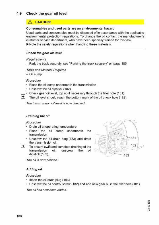
03
.13
EN
180
4.9 Check the gear oil level
CAUTION!
Consumables and used parts are an environmental hazard
Used parts and consumables must be disposed of in accordance with the applicableenvironmental protection regulations. To change the oil contact the manufacturer'scustomer service department, who have been specially trained for this task.
Note the safety regulations when handling these materials.
Check the gear oil level
Requirements
– Park the truck securely, see "Parking the truck securely" on page 105
Tools and Material Required
– Oil sump
Procedure
• Place the oil sump underneath the transmission
• Unscrew the oil dipstick (182).
• Check gear oil level, top up if necessary through the filler hole (181).
Z The oil level should reach the bottom mark of the oil check hole (182).
The transmission oil level is now checked.
Draining the oil
Procedure
• Drain oil at operating temperature.
• Place the oil sump underneath thetransmission
• Unscrew the oil drain plug (183) and drainthe transmission oil.
Z To ensure swift and complete draining of thetransmission oil, unscrew the oildipstick (182).
The oil is now drained.
Adding oil
Procedure
• Insert the oil drain plug (183).
• Unscrew the oil control screw (182) and add new gear oil in the filler hole (181).
The oil has now been added.
182
181
183
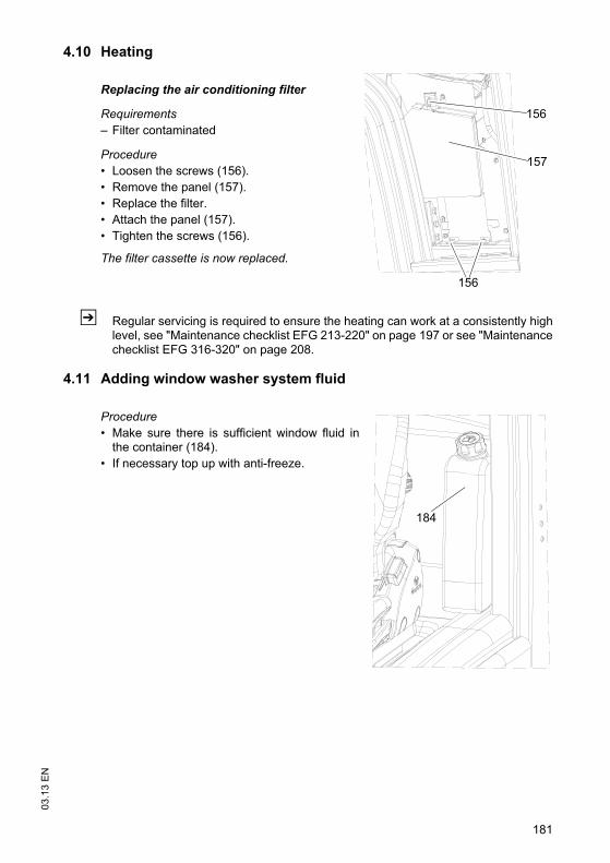
181
03
.13
EN
4.10 Heating
Replacing the air conditioning filter
Requirements
– Filter contaminated
Procedure
• Loosen the screws (156).
• Remove the panel (157).
• Replace the filter.
• Attach the panel (157).
• Tighten the screws (156).
The filter cassette is now replaced.
Z Regular servicing is required to ensure the heating can work at a consistently highlevel, see "Maintenance checklist EFG 213-220" on page 197 or see "Maintenancechecklist EFG 316-320" on page 208.
4.11 Adding window washer system fluid
Procedure
• Make sure there is sufficient window fluid inthe container (184).
• If necessary top up with anti-freeze.
157
156
156
184
03
.13
EN
182
4.12 Checking electrical fuses
WARNING!
Electric currents can cause accidents
Make sure the electrical system is voltage-free before starting work on it. Beforestarting maintenance on the electrical system:
Park the truck securely (see "Parking the truck securely" on page 105).
Press the Emergency Disconnect.
Disconnect the battery.
Remove any rings or metal bracelets etc. before working on electrical components.
CAUTION!
The use of incorrect fuses can cause fire and damage components
The use of incorrect fuses can damage the electrical system and result in fire. Thesafety and functionality of the truck cannot be ensured.
Use only fuses with the prescribed rated current, see "Fuse ratings" on page 183.
Checking electrical fuses
Requirements
– Prepare the truck for maintenance and repairs (see "Preparing the truck formaintenance and repairs" on page 171).
Procedure
• Open the rear cover of the truck, see "Opening the rear panel" on page 173.
• Remove the electrical system cap.
• Check condition and rating of the fuses in accordance with the table.
• Replace any damaged fuses in accordance with the table.
• Close the electrical system cap.
• Close the rear cover of the truck.
The electrical fuses are now checked.
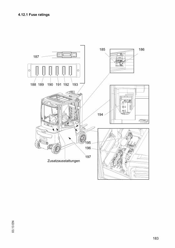
183
03
.13
EN
4.12.1 Fuse ratings
187
185 186
188 190189 191 192 193
194
195
196
197Zusatzausstattungen
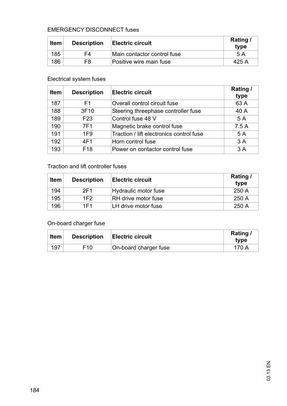
03
.13
EN
184
EMERGENCY DISCONNECT fuses
Item Description Electric circuitRating /
type
185 F4 Main contactor control fuse 5 A
186 F8 Positive wire main fuse 425 A
Electrical system fuses
Item Description Electric circuitRating /
type
187 F1 Overall control circuit fuse 63 A
188 3F10 Steering threephase controller fuse 40 A
189 F23 Control fuse 48 V 5 A
190 7F1 Magnetic brake control fuse 7.5 A
191 1F9 Traction / lift electronics control fuse 5 A
192 4F1 Horn control fuse 3 A
193 F18 Power on contactor control fuse 3 A
Traction and lift controller fuses
Item Description Electric circuitRating /
type
194 2F1 Hydraulic motor fuse 250 A
195 1F2 RH drive motor fuse 250 A
196 1F1 LH drive motor fuse 250 A
On-board charger fuse
Item Description Electric circuitRating /
type
197 F10 On-board charger fuse 170 A

185
03
.13
EN
Options fuses
Item Component Electric circuitRating /
type
198 9F1 Window wiper control fuse 5A
199 9F33 Window washer pump fuse 5A
200 9F14 Rear window wiper control fuse 5A
201 7F3 DC/DC converter control fuse 20A
202 7F4 DC/DC converter control fuse 20A
203 5F1 Search lights control fuse 10A
204 4F14 Strobe light control fuse 5A
205 F14 48 volt heater fuse 40A
206 F14.1 24 volt heater fuse 15A
207 5F11 Front LH work lights fuse 5A
57 5F11.1 Front RH work lights fuse 5A
2095F11.2 Rear LH work lights fuse
5A5F3.1 LH reverse lights fuse
2105F11.3 Rear RH work lights fuse
5A5F3.2 RH reverse lights fuse
211 5F5 Illumination control fuse 15A
212 4F4 Beacon control fuse 5A
213 9F2 Seat heating control fuse 5A
214 9F5 Window heating fuse 7.5A
215 F24 Output card fuse 20A
198
207
208
209
210
199 200201
202203
204
206205
212211
213
214215

03
.13
EN
186
4.13 Cleaning
4.13.1 Cleaning the truck
CAUTION!
Fire hazard
Do not use flammable liquids to clean the industrial truck.
Disconnect the battery before starting cleaning work.
Carry out all necessary safety measures to prevent sparking before cleaning (e.g.by short-circuiting).
CAUTION!
Risk of component damage when cleaning the truck
Cleaning with a pressure washer can result in malfunctions due to humidity.
Cover all electronic system assemblies (controllers, sensors, motors etc.) beforecleaning the truck with a pressure washer.
Do not hold the jet of the pressure washer by the marked points to avoid damagingthem (see "Identification points and data plates" on page 34).
Do not clean the truck with pressurised water.

187
03
.13
EN
Cleaning the truck
Requirements
– Prepare the truck for maintenance and repairs (see "Preparing the truck formaintenance and repairs" on page 171).
Tools and Material Required
– Water-based solvents
– Sponge or cloth
Procedure
• Clean the surface of the truck with water-based solvents and water. Use a spongeor cloth to clean.
• In particular, clean the following areas:
• Windows
• All walk-on areas
• Oil filler ports and their surroundings
• Grease nipples (before lubrication)
• Dry the truck after cleaning, e.g. with compressed air or a dry cloth.
• Carry out all the tasks in the section "Recommissioning the truck after cleaning ormaintenance work" (see "Restoring the truck to service after decommissioning" onpage 193).
The truck is now clean.

03
.13
EN
188
4.13.2 Cleaning the electrical system assemblies
CAUTION!
Risk of electrical system damage
Cleaning the assemblies (controllers, sensors, motors etc.) of the electronic systemwith water can damage the electrical system.
Do not clean the electrical system with water.
Clean the electrical system with weak suction or compressed air (use a compressorwith a water trap) and not a conductive, anti-static brush.
Cleaning the electrical system assemblies
Requirements
– Prepare the truck for maintenance and repairs (see "Preparing the truck formaintenance and repairs" on page 171).
Tools and Material Required
– Compressor with water separator
– Non-conductive, antistatic brush
Procedure
• Expose the electrical system, see "Opening the rear panel" on page 173.
• Clean the electrical system assemblies with weak suction or compressed air (usea compressor with a water trap) and not a conductive, anti-static brush.
• Fit the electrical system panel, see "Opening the rear panel" on page 173.
• Carry out all the tasks in the section "Recommissioning the truck after cleaning ormaintenance work" (see "Restoring the truck to service after decommissioning" onpage 193).
The electrical system assemblies are now clean.

189
03
.13
EN
4.14 Working on the electrical system
WARNING!
Electrical current can cause accidents
Make sure the electrical system is voltage-free before starting work on it. Thecapacitors in the controller must be completely discharged. The capacitors arecompletely discharged after approximately 10 minutes. Before starting maintenanceon the electrical system:
Only suitably trained electricians may operate on the truck's electrical system.
Before working on the electrical system, take all precautionary measures to avoidelectric shocks.
Park the truck securely (see "Parking the truck securely" on page 105).
Disconnect the battery.
Remove any rings, metal wrist bands etc.

03
.13
EN
190
4.15 Restoring the truck to service after maintenance and repairs
Procedure
• Thoroughly clean the truck, see "Cleaning" on page 186.
• Lubricate the truck according to the lubrication schedule, see "LubricationSchedule" on page 168.
• Clean the battery, grease the terminals and connect the battery.
• Charge the battery, see "Charging the battery" on page 53.
• Replace transmission oil. Condensation water could have formed.
• Replace hydraulic oil. Condensation water could have formed.
Z The manufacturer's customer service department is specially trained to carry outthese operations.
• Start up the truck, see "Preparing the Truck for Operation" on page 90.
191
03
.13
EN
5 Decommissioning the industrial truck
If the truck is to be out of service for more than a month, it must be stored in a frost-free and dry room. All necessary measures must be taken before, during and afterdecommissioning as described hereafter.
When the truck is out of service it must be jacked up so that all the wheels are clearof the ground. This is the only way of ensuring that the wheels and wheel bearingsare not damaged.
Z Jack up the truck, see "Lifting and jacking up the truck safely" on page 172.
If the truck is to be out of service for more than 6 months, agree further measures withthe manufacturer's customer service department.
03
.13
EN
192
5.1 Prior to decommissioning
Procedure
• Thoroughly clean the truck, see "Cleaning" on page 186.
• Prevent the truck from rolling away accidentally.
• Check the hydraulic oil level and replenish if necessary, see "Checking thehydraulic oil level" on page 178.
• Apply a thin layer of oil or grease to any non-painted mechanical components.
• Lubricate the truck according to the lubrication schedule, see "LubricationSchedule" on page 168.
• Charge the battery, see "Charging the battery" on page 53.
• Disconnect the battery, clean it and grease the terminals.
Z In addition, follow the battery manufacturer’s instructions.
5.2 During decommissioning
NOTE
Full discharge can damage the battery
Self-discharge can cause the battery to fully discharge. Full discharge shortens theuseful life of the battery.
Charge the battery at least every 2 months.
Z Charge the battery, see "Charging the battery" on page 53.

193
03
.13
EN
5.3 Restoring the truck to service after decommissioning
Procedure
• Thoroughly clean the truck, see "Cleaning" on page 186.
• Lubricate the truck according to the lubrication schedule, see "LubricationSchedule" on page 168.
• Clean the battery, grease the terminals and connect the battery.
• Charge the battery, see "Charging the battery" on page 53.
• Replace transmission oil. Condensation water could have formed.
• Replace hydraulic oil. Condensation water could have formed.
Z The manufacturer's customer service department is specially trained to carry outthese operations.
• Start up the truck, see "Preparing the Truck for Operation" on page 90.

03
.13
EN
194
6 Safety tests to be performed at intervals and after unusual incidents
Z Perform a safety check in accordance with national regulations. The manufacturerrecommends the truck be checked to FEM guideline 4.004. The manufacturer hasa service department specially trained for these tasks.
The truck must be inspected at least annually (refer to national regulations) or afterany unusual event by a qualified inspector. The inspector shall assess the conditionof the system from purely a safety viewpoint, without regard to operational oreconomic circumstances. The inspector must be sufficiently instructed andexperienced to be able to assess the condition of the truck and the effectiveness ofthe safety mechanisms based on the technical regulations and principles governingthe inspection of forklift trucks.
A thorough test of the truck must be undertaken with regard to its technical conditionfrom a safety aspect. The truck must also be examined for damage caused bypossible improper use. A test report shall be produced. The test results must be keptfor at least the next 2 inspections.
The proprietor is responsible for ensuring that faults are immediately rectified.
Z A test plaque is attached to the truck as proof that it has passed the safetyinspection. This plaque indicates the due date for the next inspection.

195
03
.13
EN
7 Final de-commissioning, disposal
Z Final de-commissioning or disposal of the truck in must be performed inaccordance with the regulations of the country of use. In particular, regulationsgoverning the disposal of batteries, consumables and electronic and electricalsystems must be observed.
The truck must only be disassembled by trained personnel in accordance with theprocedures as specified by the manufacturer.
8 Human vibration measurement
Z Vibrations that affect the operator over the course of the day are known as humanvibrations. Excessive human vibrations will cause the operator long term healthproblems. The European "2002/44/EC/Vibration" operator directive has thereforebeen established to protect operators. To help operators to assess the applicationsituation, the manufacturer offers a service of measuring these human vibrations.

03
.13
EN
196
9 Servicing and Inspection
WARNING!
Risk of accident due to neglected maintenance
Failure to perform regular servicing can lead to truck failure and poses a potentialhazard to personnel and equipment.
Thorough and expert servicing is one of the most important requirements for thesafe operation of the industrial truck.
The application conditions of an industrial truck have a considerable impact oncomponent wear. The following service intervals are based on single-shift operationunder normal operating conditions. They must be reduced accordingly if theequipment is to be used in conditions of extreme dust, temperature fluctuations ormultiple shifts.
NOTE
To prevent damage due to wear, the manufacturer recommends an on-siteapplication analysis to agree on appropriate service intervals.
The following maintenance checklist lists the activities to be performed and therespective intervals to be observed. Maintenance intervals are defined as:
Z "W" maintenance-interval activities should be performed by the operatingcompany.
During the run-in period,after approx. 100 service hours, the owner must check thewheel nuts/bolts and re-tighten if necessary.
W = Every 50 service hours, at least weekly
A = Every 500 service hours
B = Every 1000 service hours, or at least annually
C = Every 2000 service hours, or at least annually
t = Standard maintenance interval
k =Cold store maintenance interval (in addition to standard maintenance interval)

197
03
.13
EN
10 Maintenance checklist EFG 213-220
10.1 Operating company
10.1.1 Standard equipment
Braking W A B C
1 Test brakes. t
Electrical System W A B C
1Test warning and safety devices in accordance with operating instructions.
t
2 Test Emergency Disconnect switch. t
Power Supply W A B C
1Check battery cable connections are secure, grease terminals if necessary.
t
2 Check battery and battery components. t
3 Check acid level and add demineralised water if necessary. t
4Check battery connector for damage, test it and make sure it is secure.
t
Travel W A B C
1Check the wheels for wear and damage. Make sure they are tight and check the compressed air if necessary.
t
Chassis and Superstructure W A B C
1 Check doors and/or covers. t
2 Check labels are legible and complete. t
3Check overhead guard and / or cab are secure and check for damage.
t
4 Test driver's seat restraint system and check for damage. t
Hydraulic Operations W A B C
1 Check load chain lubrication and lubricate if necessary. t
2Check running surfaces of the mast for wear and damage, and lubricate if necessary.
t
3 Test hydraulic system. t
4Check cylinders, hydraulic ports, lines and hoses for leaks and damage.
t
5 Check hydraulic oil level and top up if necessary. t
6 Check forks or load handler for wear and damage. t
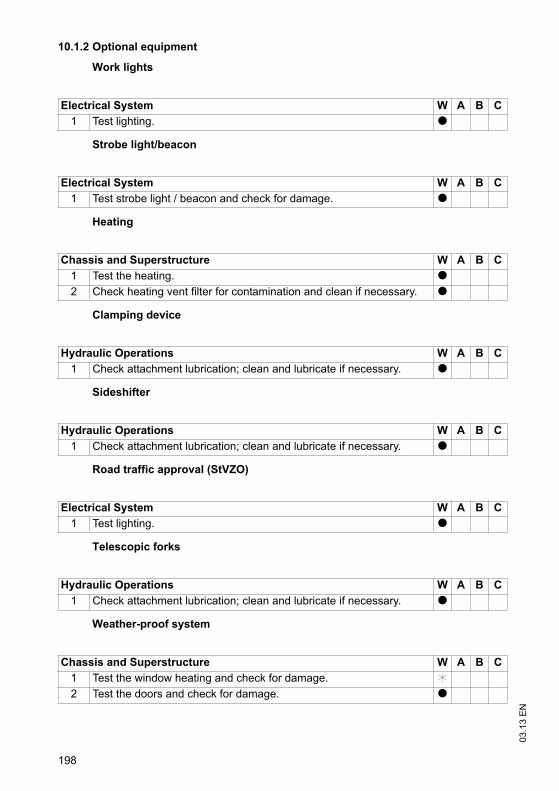
03
.13
EN
198
10.1.2 Optional equipment
Work lights
Strobe light/beacon
Heating
Clamping device
Sideshifter
Road traffic approval (StVZO)
Telescopic forks
Weather-proof system
Electrical System W A B C
1 Test lighting. t
Electrical System W A B C
1 Test strobe light / beacon and check for damage. t
Chassis and Superstructure W A B C
1 Test the heating. t
2 Check heating vent filter for contamination and clean if necessary. t
Hydraulic Operations W A B C
1 Check attachment lubrication; clean and lubricate if necessary. t
Hydraulic Operations W A B C
1 Check attachment lubrication; clean and lubricate if necessary. t
Electrical System W A B C
1 Test lighting. t
Hydraulic Operations W A B C
1 Check attachment lubrication; clean and lubricate if necessary. t
Chassis and Superstructure W A B C
1 Test the window heating and check for damage. k
2 Test the doors and check for damage. t
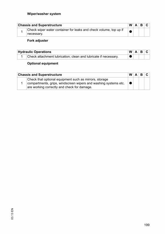
199
03
.13
EN
Wiper/washer system
Fork adjuster
Optional equipment
Chassis and Superstructure W A B C
1Check wiper water container for leaks and check volume, top up if necessary.
t
Hydraulic Operations W A B C
1 Check attachment lubrication; clean and lubricate if necessary. t
Chassis and Superstructure W A B C
1Check that optional equipment such as mirrors, storage compartments, grips, windscreen wipers and washing systems etc. are working correctly and check for damage.
t

03
.13
EN
200
10.2 Customer service
10.2.1 Standard equipment
Brakes W A B C
1 Test brakes. t
2 Check magnetic brake air gap. t
3 Check brake mechanism, adjust and lubricate if necessary. t
Electrical System W A B C
1 Test cable and motor attachments. t
2Test warning and safety devices in accordance with operating instructions.
t
3 Test displays and controls. t
4 Test micro switch and adjust if necessary. t
5 Test Emergency Disconnect switch. t
6 Check contactors and/or relays. t
7 Test fan and check for dirt and damage. t
8 Check fuse ratings. t
9 Carry out a frame leakage test. t
10Check electric wiring for damage (insulation damage, connections). Make sure wire connections are secure.
t
Power Supply W A B C
1Check battery cable connections are secure, grease terminals if necessary.
t
2 Check battery and battery components. t
3 Check acid density and battery voltage. t
4Check battery connector for damage, test it and make sure it is secure.
t
5 Check safety labelling is present. t
Travel W A B C
1Check transmission oil level or grease filling of the transmission and top up if necessary.
t
2 Check transmission for noise and leakage. t
3 Note: Replace transmission oil after 10000 service hours.
4Check the wheels for wear and damage. Make sure they are tight and check the compressed air if necessary.
t
5 Check wheel suspension and attachment. t
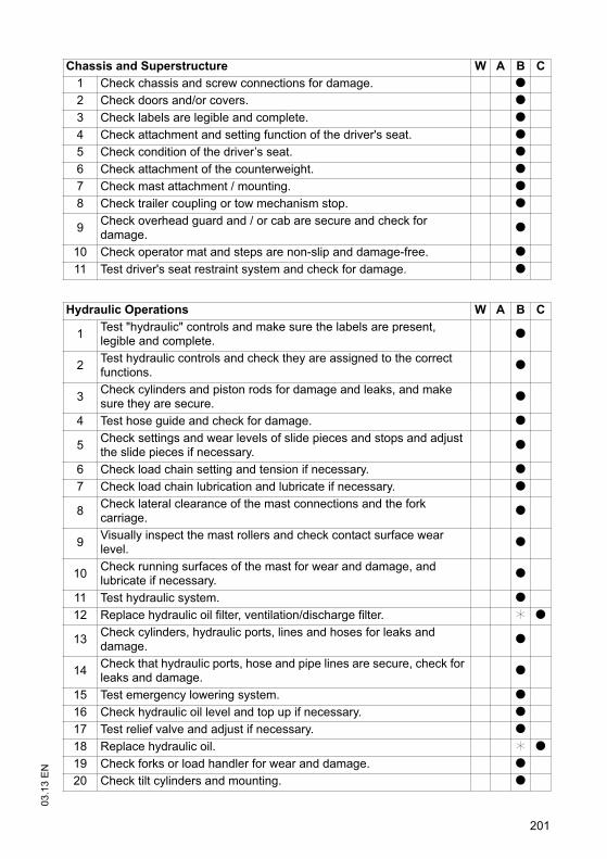
201
03
.13
EN
Chassis and Superstructure W A B C
1 Check chassis and screw connections for damage. t
2 Check doors and/or covers. t
3 Check labels are legible and complete. t
4 Check attachment and setting function of the driver's seat. t
5 Check condition of the driver’s seat. t
6 Check attachment of the counterweight. t
7 Check mast attachment / mounting. t
8 Check trailer coupling or tow mechanism stop. t
9Check overhead guard and / or cab are secure and check for damage.
t
10 Check operator mat and steps are non-slip and damage-free. t
11 Test driver's seat restraint system and check for damage. t
Hydraulic Operations W A B C
1Test "hydraulic" controls and make sure the labels are present, legible and complete.
t
2Test hydraulic controls and check they are assigned to the correct functions.
t
3Check cylinders and piston rods for damage and leaks, and make sure they are secure.
t
4 Test hose guide and check for damage. t
5Check settings and wear levels of slide pieces and stops and adjust the slide pieces if necessary.
t
6 Check load chain setting and tension if necessary. t
7 Check load chain lubrication and lubricate if necessary. t
8Check lateral clearance of the mast connections and the fork carriage.
t
9Visually inspect the mast rollers and check contact surface wear level.
t
10Check running surfaces of the mast for wear and damage, and lubricate if necessary.
t
11 Test hydraulic system. t
12 Replace hydraulic oil filter, ventilation/discharge filter. k t
13Check cylinders, hydraulic ports, lines and hoses for leaks and damage.
t
14Check that hydraulic ports, hose and pipe lines are secure, check for leaks and damage.
t
15 Test emergency lowering system. t
16 Check hydraulic oil level and top up if necessary. t
17 Test relief valve and adjust if necessary. t
18 Replace hydraulic oil. k t
19 Check forks or load handler for wear and damage. t
20 Check tilt cylinders and mounting. t

03
.13
EN
202
10.2.2 Optional equipment
Discharge strap
Audible warning devices
Trailer coupling
Aquamatik
Work Platform
Agreed performance levels W A B C
1Carry out a test run with rated load, if necessary with a customer-specific load.
t
2 Lubricate truck according to the lubrication schedule. t
3 Demonstration after servicing. t
Steering W A B C
1 Test electric steering and its components. t
2 Check mechanical parts of steering column. t
3 Check steering block for wear and damage t
Electrical System W A B C
1 Check anti-static discharge strap is present and not damaged. t
Electrical System W A B C
1Test the buzzer / warning alarm, check for damage and make sure it is secure.
t
Chassis and Superstructure W A B C
1 Check trailer coupling or tow mechanism stop. t
Power Supply W A B C
1Test Aquamatik plug, hose connections and float and check for leaks.
t
2 Test flow indicator and check for leaks. t
Hydraulic Operations W A B C
1Check attachment is properly secured to the truck and the supporting elements.
t

203
03
.13
EN
Work lights
Battery refill system
Battery replacement system
Strobe light/beacon
Data recorder
Radio data
On-board charger
Electrical System W A B C
1 Test lighting. t
Power Supply W A B C
1 Test battery refill system and check for leaks. t
Power Supply W A B C
1 Check safety labels are present. t
2 Check lock is present and test it. t
Electrical System W A B C
1 Test strobe light / beacon and check for damage. t
Electrical System W A B C
1 Check data recorder is secure and check for damage. t
System Components W A B C
1Test scanner and terminal, check for damage and make sure they are secure and clean.
t
2 Check fuse ratings. t
3 Check wiring is secure and check for damage. t
Charger W A B C
1 Check mains connector and mains cable. t
2 Test the immobiliser on trucks with an on-board charger. t
3Check the wires and electrical connections are secure and not damaged.
t
4Carry out potential measurement on chassis while charging is in progress.
t
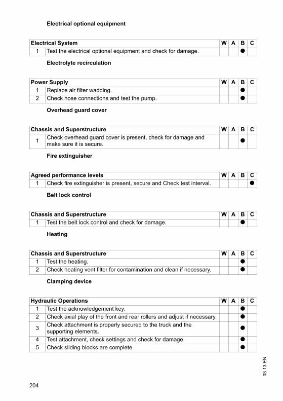
03
.13
EN
204
Electrical optional equipment
Electrolyte recirculation
Overhead guard cover
Fire extinguisher
Belt lock control
Heating
Clamping device
Electrical System W A B C
1 Test the electrical optional equipment and check for damage. t
Power Supply W A B C
1 Replace air filter wadding. t
2 Check hose connections and test the pump. t
Chassis and Superstructure W A B C
1Check overhead guard cover is present, check for damage and make sure it is secure.
t
Agreed performance levels W A B C
1 Check fire extinguisher is present, secure and Check test interval. t
Chassis and Superstructure W A B C
1 Test the belt lock control and check for damage. t
Chassis and Superstructure W A B C
1 Test the heating. t
2 Check heating vent filter for contamination and clean if necessary. t
Hydraulic Operations W A B C
1 Test the acknowledgement key. t
2 Check axial play of the front and rear rollers and adjust if necessary. t
3Check attachment is properly secured to the truck and the supporting elements.
t
4 Test attachment, check settings and check for damage. t
5 Check sliding blocks are complete. t
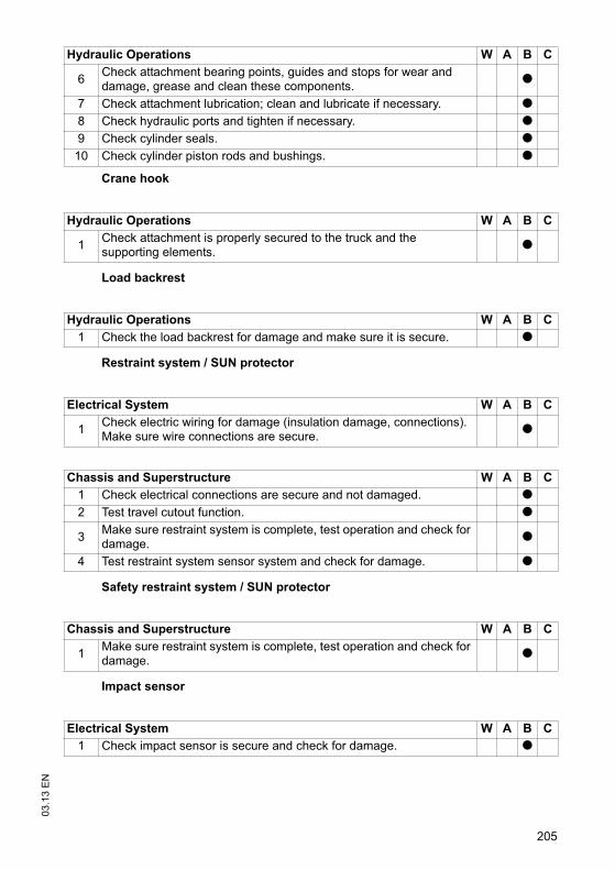
205
03
.13
EN
Crane hook
Load backrest
Restraint system / SUN protector
Safety restraint system / SUN protector
Impact sensor
6Check attachment bearing points, guides and stops for wear and damage, grease and clean these components.
t
7 Check attachment lubrication; clean and lubricate if necessary. t
8 Check hydraulic ports and tighten if necessary. t
9 Check cylinder seals. t
10 Check cylinder piston rods and bushings. t
Hydraulic Operations W A B C
1Check attachment is properly secured to the truck and the supporting elements.
t
Hydraulic Operations W A B C
1 Check the load backrest for damage and make sure it is secure. t
Electrical System W A B C
1Check electric wiring for damage (insulation damage, connections). Make sure wire connections are secure.
t
Chassis and Superstructure W A B C
1 Check electrical connections are secure and not damaged. t
2 Test travel cutout function. t
3Make sure restraint system is complete, test operation and check for damage.
t
4 Test restraint system sensor system and check for damage. t
Chassis and Superstructure W A B C
1Make sure restraint system is complete, test operation and check for damage.
t
Electrical System W A B C
1 Check impact sensor is secure and check for damage. t
Hydraulic Operations W A B C

03
.13
EN
206
Sideshifter
Seat heating
Road traffic approval (StVZO)
Telescopic forks
Hydraulic Operations W A B C
1 Check axial play of the front and rear rollers and adjust if necessary. t
2Check attachment is properly secured to the truck and the supporting elements.
t
3 Test attachment, check settings and check for damage. t
4 Check sliding blocks are complete. t
5Check attachment bearing points, guides and stops for wear and damage, grease and clean these components.
t
6 Check attachment lubrication; clean and lubricate if necessary. t
7 Check hydraulic ports and tighten if necessary. t
8 Test the sideshifter, check settings and check for damage. t
9 Check cylinder seals. t
10 Check cylinder piston rods and bushings. t
Electrical System W A B C
1Check electric wiring for damage (insulation damage, connections). Make sure wire connections are secure.
t
Electrical System W A B C
1 Test lighting. t
Hydraulic Operations W A B C
1Check attachment is properly secured to the truck and the supporting elements.
t
2 Test attachment, check settings and check for damage. t
3Check attachment bearing points, guides and stops for wear and damage, grease and clean these components.
t
4 Check attachment lubrication; clean and lubricate if necessary. t
5 Check hydraulic ports and tighten if necessary. t
6 Check cylinder seals. t
7Check that hydraulic ports, hose and pipe lines are secure, check for leaks and damage.
t
8Check piston and piston rod for damage, check setting and adjust if necessary.
t

207
03
.13
EN
Boom
Video system
Weigher sensors / switches
Weather-proof system
Wiper/washer system
Fork adjuster
Hydraulic Operations W A B C
1Check attachment is properly secured to the truck and the supporting elements.
t
System Components W A B C
1 Check wiring is secure and check for damage. t
2 Test the camera, make sure it is secured and clean. t
3 Test the monitor, make sure it is secured and clean. t
Electrical System W A B C
1 Test weigher system and check for damage. t
Electrical System W A B C
1 Check fuse ratings. t
Chassis and Superstructure W A B C
1 Test the window heating and check for damage. t
2 Test the doors and check for damage. t
Chassis and Superstructure W A B C
1Check wiper water container for leaks and check volume, top up if necessary.
t
2 Test windscreen wipers and check for damage, replace if necessary. t
Hydraulic Operations W A B C
1 Check axial play of the front and rear rollers and adjust if necessary. t
2Check attachment is properly secured to the truck and the supporting elements.
t
3 Test attachment, check settings and check for damage. t
4 Check sliding blocks are complete. t
5Check attachment bearing points, guides and stops for wear and damage, grease and clean these components.
t

03
.13
EN
208
Access module
Optional equipment
Issued on: 02.01.2013 10:32:51
11 Maintenance checklist EFG 316-320
11.1 Operating company
11.1.1 Standard equipment
6 Check attachment lubrication; clean and lubricate if necessary. t
7 Check hydraulic ports and tighten if necessary. t
8 Test the fork positioner and check for damage. t
9 Check cylinder seals. t
10 Check cylinder piston rods and bushings. t
Electrical System W A B C
1 Test access module, check for damage and make sure it is secure. t
Chassis and Superstructure W A B C
1Check that optional equipment such as mirrors, storage compartments, grips, windscreen wipers and washing systems etc. are working correctly and check for damage.
t
Brakes W A B C
1 Test brakes. t
Electrical System W A B C
1Test warning and safety devices in accordance with operating instructions.
t
2 Test Emergency Disconnect switch. t
Power Supply W A B C
1Check battery cable connections are secure, grease terminals if necessary.
t
2 Check battery and battery components. t
3 Check acid level and add demineralised water if necessary. t
4Check battery connector for damage, test it and make sure it is secure.
t
Hydraulic Operations W A B C
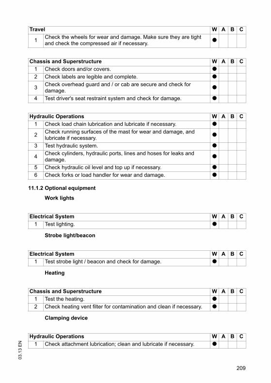
209
03
.13
EN
11.1.2 Optional equipment
Work lights
Strobe light/beacon
Heating
Clamping device
Travel W A B C
1Check the wheels for wear and damage. Make sure they are tight and check the compressed air if necessary.
t
Chassis and Superstructure W A B C
1 Check doors and/or covers. t
2 Check labels are legible and complete. t
3Check overhead guard and / or cab are secure and check for damage.
t
4 Test driver's seat restraint system and check for damage. t
Hydraulic Operations W A B C
1 Check load chain lubrication and lubricate if necessary. t
2Check running surfaces of the mast for wear and damage, and lubricate if necessary.
t
3 Test hydraulic system. t
4Check cylinders, hydraulic ports, lines and hoses for leaks and damage.
t
5 Check hydraulic oil level and top up if necessary. t
6 Check forks or load handler for wear and damage. t
Electrical System W A B C
1 Test lighting. t
Electrical System W A B C
1 Test strobe light / beacon and check for damage. t
Chassis and Superstructure W A B C
1 Test the heating. t
2 Check heating vent filter for contamination and clean if necessary. t
Hydraulic Operations W A B C
1 Check attachment lubrication; clean and lubricate if necessary. t
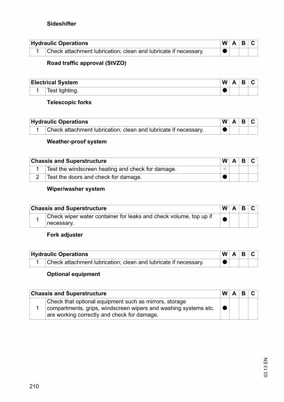
03
.13
EN
210
Sideshifter
Road traffic approval (StVZO)
Telescopic forks
Weather-proof system
Wiper/washer system
Fork adjuster
Optional equipment
Hydraulic Operations W A B C
1 Check attachment lubrication; clean and lubricate if necessary. t
Electrical System W A B C
1 Test lighting. t
Hydraulic Operations W A B C
1 Check attachment lubrication; clean and lubricate if necessary. t
Chassis and Superstructure W A B C
1 Test the windscreen heating and check for damage. k
2 Test the doors and check for damage. t
Chassis and Superstructure W A B C
1Check wiper water container for leaks and check volume, top up if necessary.
t
Hydraulic Operations W A B C
1 Check attachment lubrication; clean and lubricate if necessary. t
Chassis and Superstructure W A B C
1Check that optional equipment such as mirrors, storage compartments, grips, windscreen wipers and washing systems etc. are working correctly and check for damage.
t

211
03
.13
EN
11.2 Customer service
11.2.1 Standard equipment
Brakes W A B C
1 Test brakes. t
2 Check magnetic brake air gap. t
3 Check brake mechanism, adjust and lubricate if necessary. t
Electrical System W A B C
1 Test cable and motor attachments. t
2Test warning and safety devices in accordance with operating instructions.
t
3 Test displays and controls. t
4 Test micro switch and adjust if necessary. t
5 Test Emergency Disconnect switch. t
6 Check contactors and/or relays. t
7 Test fan and check for dirt and damage. t
8 Check fuse ratings. t
9 Carry out a frame leakage test. t
10Check electric wiring for damage (insulation damage, connections). Make sure wire connections are secure.
t
Power Supply W A B C
1Check battery cable connections are secure, grease terminals if necessary.
t
2 Check battery and battery components. t
3 Check acid density and battery voltage. t
4Check battery connector for damage, test it and make sure it is secure.
t
5 Check safety labels are present. t
Travel W A B C
1Check transmission oil level or grease filling of the transmission and top up if necessary.
t
2 Check transmission for noise and leakage. t
3 Note: Replace transmission oil after 10000 service hours.
4Check the wheels for wear and damage. Make sure they are tight and check the compressed air if necessary.
t
5 Check wheel suspension and attachment. t

03
.13
EN
212
Chassis and Superstructure W A B C
1 Check chassis and screw connections for damage. t
2 Check doors and/or covers. t
3 Check labels are legible and complete. t
4 Check attachment and setting function of the driver's seat. t
5 Check condition of the driver’s seat. t
6 Check attachment of the counterweight. t
7 Check mast attachment / mounting. t
8 Check trailer coupling or tow mechanism stop. t
9Check overhead guard and / or cab are secure and check for damage.
t
10 Check operator mat and steps are non-slip and damage-free. t
11 Test driver's seat restraint system and check for damage. t
Hydraulic Operations W A B C
1Test "hydraulic" controls and make sure the labels are present, legible and complete.
t
2Test hydraulic controls and check they are assigned to the correct functions.
t
3Check cylinders and piston rods for damage and leaks, and make sure they are secure.
t
4 Test hose guide and check for damage. t
5Check settings and wear levels of slide pieces and stops and adjust the slide pieces if necessary.
t
6 Check load chain setting and tension if necessary. t
7 Check load chain lubrication and lubricate if necessary. t
8Check lateral clearance of the mast connections and the fork carriage.
t
9Visually inspect the mast rollers and check contact surface wear level.
t
10Check running surfaces of the mast for wear and damage, and lubricate if necessary.
t
11 Test hydraulic system. t
12 Replace hydraulic oil filter, ventilation/discharge filter. k t
13Check cylinders, hydraulic ports, lines and hoses for leaks and damage.
t
14Check that hydraulic ports, hose and pipe lines are secure, check for leaks and damage.
t
15 Test emergency lowering system. t
16 Check hydraulic oil level and top up if necessary. t
17 Test relief valve and adjust if necessary. t
18 Replace hydraulic oil. k t
19 Check forks or load handler for wear and damage. t
20 Check tilt cylinders and mounting. t

213
03
.13
EN
11.2.2 Optional equipment
Discharge strap
Audible warning devices
Trailer coupling
Aquamatik
Agreed performance levels W A B C
1Carry out a test run with rated load, if necessary with a customer-specific load.
t
2 Lubricate truck according to the lubrication schedule. t
3 Demonstration after servicing. t
Steering W A B C
1 Check the hydraulic oil level of the hydraulic steering. t
2 Test the hydraulic steering for leaks. t
3 Check steering hoses and lines. t
4 Check steering axle and steering knuckle for wear and damage. t
5 Check stub axle and adjust if necessary. t
6 Test electric / hydraulic steering and its components. t
7 Check mechanical parts of steering column. t
Electrical System W A B C
1 Check anti-static discharge strap is present and not damaged. t
Electrical System W A B C
1Test the buzzer / warning alarm, check for damage and make sure it is secure.
t
Chassis and Superstructure W A B C
1 Check trailer coupling or tow mechanism stop. t
Power Supply W A B C
1Test Aquamatik plug, hose connections and float and check for leaks.
t
2 Test flow indicator and check for leaks. t

03
.13
EN
214
Work Platform
Work lights
Battery refill system
Battery replacement system
Strobe light/beacon
Data recorder
Radio data
Hydraulic Operations W A B C
1Check attachment is properly secured to the truck and the supporting elements.
t
Electrical System W A B C
1 Test lighting. t
Power Supply W A B C
1 Test battery refill system and check for leaks. t
Power Supply W A B C
1 Check safety labels are present. t
2 Check lock is present and test it. t
Electrical System W A B C
1 Test strobe light / beacon and check for damage. t
Electrical System W A B C
1 Check data recorder is secure and check for damage. t
System Components W A B C
1Test scanner and terminal, check for damage and make sure they are secure and clean.
t
2 Check fuse ratings. t
3 Check wiring is secure and check for damage. t
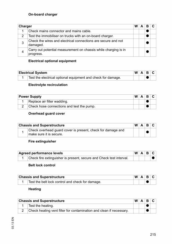
215
03
.13
EN
On-board charger
Electrical optional equipment
Electrolyte recirculation
Overhead guard cover
Fire extinguisher
Belt lock control
Heating
Charger W A B C
1 Check mains connector and mains cable. t
2 Test the immobiliser on trucks with an on-board charger. t
3Check the wires and electrical connections are secure and not damaged.
t
4Carry out potential measurement on chassis while charging is in progress.
t
Electrical System W A B C
1 Test the electrical optional equipment and check for damage. t
Power Supply W A B C
1 Replace air filter wadding. t
2 Check hose connections and test the pump. t
Chassis and Superstructure W A B C
1Check overhead guard cover is present, check for damage and make sure it is secure.
t
Agreed performance levels W A B C
1 Check fire extinguisher is present, secure and Check test interval. t
Chassis and Superstructure W A B C
1 Test the belt lock control and check for damage. t
Chassis and Superstructure W A B C
1 Test the heating. t
2 Check heating vent filter for contamination and clean if necessary. t
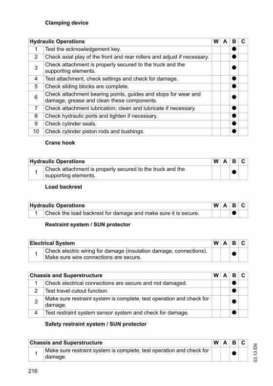
03
.13
EN
216
Clamping device
Crane hook
Load backrest
Restraint system / SUN protector
Safety restraint system / SUN protector
Hydraulic Operations W A B C
1 Test the acknowledgement key. t
2 Check axial play of the front and rear rollers and adjust if necessary. t
3Check attachment is properly secured to the truck and the supporting elements.
t
4 Test attachment, check settings and check for damage. t
5 Check sliding blocks are complete. t
6Check attachment bearing points, guides and stops for wear and damage, grease and clean these components.
t
7 Check attachment lubrication; clean and lubricate if necessary. t
8 Check hydraulic ports and tighten if necessary. t
9 Check cylinder seals. t
10 Check cylinder piston rods and bushings. t
Hydraulic Operations W A B C
1Check attachment is properly secured to the truck and the supporting elements.
t
Hydraulic Operations W A B C
1 Check the load backrest for damage and make sure it is secure. t
Electrical System W A B C
1Check electric wiring for damage (insulation damage, connections). Make sure wire connections are secure.
t
Chassis and Superstructure W A B C
1 Check electrical connections are secure and not damaged. t
2 Test travel cutout function. t
3Make sure restraint system is complete, test operation and check for damage.
t
4 Test restraint system sensor system and check for damage. t
Chassis and Superstructure W A B C
1Make sure restraint system is complete, test operation and check for damage.
t

217
03
.13
EN
Impact sensor
Sideshifter
Seat heating
Road traffic approval (StVZO)
Telescopic forks
Electrical System W A B C
1 Check impact sensor is secure and check for damage. t
Hydraulic Operations W A B C
1 Check axial play of the front and rear rollers and adjust if necessary. t
2Check attachment is properly secured to the truck and the supporting elements.
t
3 Test attachment, check settings and check for damage. t
4 Check sliding blocks are complete. t
5Check attachment bearing points, guides and stops for wear and damage, grease and clean these components.
t
6 Check attachment lubrication; clean and lubricate if necessary. t
7 Check hydraulic ports and tighten if necessary. t
8 Test the sideshifter, check settings and check for damage. t
9 Check cylinder seals. t
10 Check cylinder piston rods and bushings. t
Electrical System W A B C
1Check electric wiring for damage (insulation damage, connections). Make sure wire connections are secure.
t
Electrical System W A B C
1 Test lighting. t
Hydraulic Operations W A B C
1Check attachment is properly secured to the truck and the supporting elements.
t
2 Test attachment, check settings and check for damage. t
3Check attachment bearing points, guides and stops for wear and damage, grease and clean these components.
t

03
.13
EN
218
Boom
Video system
Weigher sensors / switches
Weather-proof system
Wiper/washer system
4 Check attachment lubrication; clean and lubricate if necessary. t
5 Check hydraulic ports and tighten if necessary. t
6 Check cylinder seals. t
7Check that hydraulic ports, hose and pipe lines are secure, check for leaks and damage.
t
8Check piston and piston rod for damage, check setting and adjust if necessary.
t
Hydraulic Operations W A B C
1Check attachment is properly secured to the truck and the supporting elements.
t
System Components W A B C
1 Check wiring is secure and check for damage. t
2 Test the camera, make sure it is secured and clean. t
3 Test the monitor, make sure it is secured and clean. t
Electrical System W A B C
1 Test weigher system and check for damage. t
Electrical System W A B C
1 Check fuse ratings. t
Chassis and Superstructure W A B C
1 Test the windscreen heating and check for damage. t
2 Test the doors and check for damage. t
Chassis and Superstructure W A B C
1Check wiper water container for leaks and check volume, top up if necessary.
t
2 Test windscreen wipers and check for damage, replace if necessary. t
Hydraulic Operations W A B C
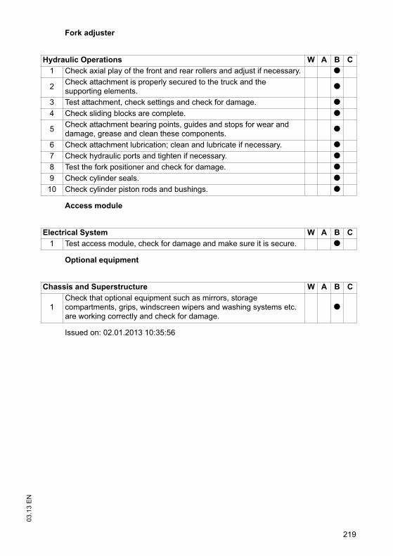
219
03
.13
EN
Fork adjuster
Access module
Optional equipment
Issued on: 02.01.2013 10:35:56
Hydraulic Operations W A B C
1 Check axial play of the front and rear rollers and adjust if necessary. t
2Check attachment is properly secured to the truck and the supporting elements.
t
3 Test attachment, check settings and check for damage. t
4 Check sliding blocks are complete. t
5Check attachment bearing points, guides and stops for wear and damage, grease and clean these components.
t
6 Check attachment lubrication; clean and lubricate if necessary. t
7 Check hydraulic ports and tighten if necessary. t
8 Test the fork positioner and check for damage. t
9 Check cylinder seals. t
10 Check cylinder piston rods and bushings. t
Electrical System W A B C
1 Test access module, check for damage and make sure it is secure. t
Chassis and Superstructure W A B C
1Check that optional equipment such as mirrors, storage compartments, grips, windscreen wipers and washing systems etc. are working correctly and check for damage.
t

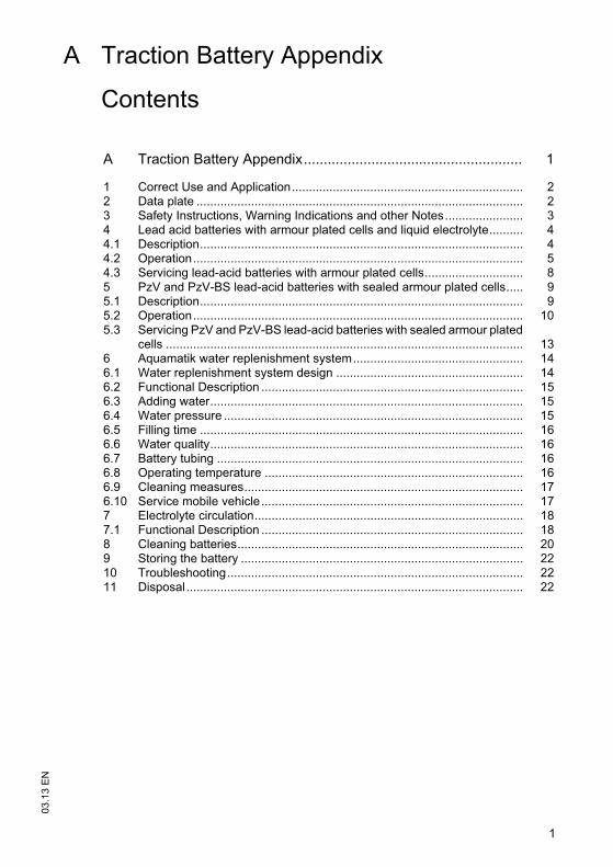
1
03
.13
EN
A Traction Battery Appendix
Contents
A Traction Battery Appendix....................................................... 1
1 Correct Use and Application.................................................................... 22 Data plate ................................................................................................ 23 Safety Instructions, Warning Indications and other Notes....................... 34 Lead acid batteries with armour plated cells and liquid electrolyte.......... 44.1 Description............................................................................................... 44.2 Operation................................................................................................. 54.3 Servicing lead-acid batteries with armour plated cells............................. 85 PzV and PzV-BS lead-acid batteries with sealed armour plated cells..... 95.1 Description............................................................................................... 95.2 Operation................................................................................................. 105.3 Servicing PzV and PzV-BS lead-acid batteries with sealed armour plated
cells ......................................................................................................... 136 Aquamatik water replenishment system.................................................. 146.1 Water replenishment system design ....................................................... 146.2 Functional Description ............................................................................. 156.3 Adding water............................................................................................ 156.4 Water pressure ........................................................................................ 156.5 Filling time ............................................................................................... 166.6 Water quality............................................................................................ 166.7 Battery tubing .......................................................................................... 166.8 Operating temperature ............................................................................ 166.9 Cleaning measures.................................................................................. 176.10 Service mobile vehicle............................................................................. 177 Electrolyte circulation............................................................................... 187.1 Functional Description ............................................................................. 188 Cleaning batteries.................................................................................... 209 Storing the battery ................................................................................... 2210 Troubleshooting....................................................................................... 2211 Disposal................................................................................................... 22
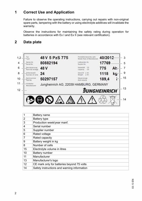
03
.13
EN
2
1 Correct Use and Application
Failure to observe the operating instructions, carrying out repairs with non-originalspare parts, tampering with the battery or using electrolyte additives will invalidate thewarranty.
Observe the instructions for maintaining the safety rating during operation forbatteries in accordance with Ex I and Ex II (see relevant certification).
2 Data plate
1,2
4
8
10
11
6
3
5
9
7
1213
14
15
1 Battery name
2 Battery type
3 Production week/year manf.
4 Serial number
5 Supplier number
6 Rated voltage
7 Rated capacity
9 Battery weight in kg
8 Number of cells
15 Electrolyte volume in litres
10 Battery number
11 Manufacturer
13 Manufacturer's logo
12 CE mark only for batteries beyond 75 volts
14 Safety instructions and warning information

3
03
.13
EN
3 Safety Instructions, Warning Indications and other Notes
Used batteries must be treated as hazardous waste.
These batteries are marked with the recycling symbol and the sign showing a crossed-out rubbish bin, and should not be disposed of with ordinary household waste. waste.
Buy-back terms and type of recycling are to be agreed with the manufacturer as described in § 8 of the battery legislation.
Do not smoke!
No naked flames, glowing embers or sparks near the battery - fire and explosion hazard!
Avoid fire and explosion hazards and short circuits due to overheating!
Keep away from naked flames and strong heat sources.
Always wear protective clothing (e.g. safety goggles and safety gloves) when working on cells and batteries. batteries.Always wash your hands after completing the work. Use insulated tools only. Do not physically alter the battery, strike, crush, compress, notch, dent or modify it in any way.
Hazardous electric voltage! The metal parts of the battery cells are permanently live. Therefore do not place any foreign objects or tools on the battery.Observe national health and safety regulations.
If the materials leak, do not inhale the fumes. Wear safety gloves.
Follow the user instructions and keep them in a visible position in the charging area.
Work on the batteries should be performed only as instructed by specialist personnel.
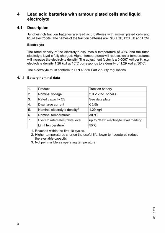
03
.13
EN
4
4 Lead acid batteries with armour plated cells and liquid electrolyte
4.1 Description
Jungheinrich traction batteries are lead acid batteries with armour plated cells andliquid electrolyte. The names of the traction batteries are PzS, PzB, PzS Lib and PzM.
Electrolyte
The rated density of the electrolyte assumes a temperature of 30°C and the ratedelectrolyte level is fully charged. Higher temperatures will reduce, lower temperatureswill increase the electrolyte density. The adjustment factor is ± 0.0007 kg/l per K, e.g.electrolyte density 1.28 kg/l at 45°C corresponds to a density of 1.29 kg/l at 30°C.
The electrolyte must conform to DIN 43530 Part 2 purity regulations.
4.1.1 Battery nominal data
1. Product Traction battery
2. Nominal voltage 2.0 V x no. of cells
3. Rated capacity C5 See data plate
4. Discharge current C5/5h
5. Nominal electrolyte density1
1. Reached within the first 10 cycles.
1.29 kg/l
6. Nominal temperature2
2. Higher temperatures shorten the useful life, lower temperatures reduce the available capacity.
30 °C
7. System rated electrolyte level up to "Max" electrolyte level marking
Limit temperature3
3. Not permissible as operating temperature.
55°C
5
03
.13
EN
4.2 Operation
4.2.1 Commissioning unfilled batteries
Z The operations required must be carried out by the manufacturer's customerservice department or a customer service organisation authorised by themanufacturer.
4.2.2 Commissioning filled and charged batteries
Checks and operations to be performed before starting daily work
Procedure
• Make sure the battery is in physically good condition.
• Make sure the terminals are correct (positive to positive and negative to negative)and check that contacts on the battery terminal conducting system are secure.
• Check the terminal screw torques (M10 = 23 ±1 Nm) of the terminal conductors andconnectors.
• Charge up the battery.
• Check the electrolyte level.
Z The electrolyte level must be above the cell baffle or the top of the separator.
• Add electrolyte with distilled water up to the nominal level.
Checks completed.
4.2.3 Discharging the battery
Z To achieve an optimum useful life avoid operational discharge of more than 80% ofnominal capacity (full discharge). This corresponds to a minimum electrolytedensity of 1.13 kg/l at the end of the discharge. Recharge a discharged batteryimmediately.
03
.13
EN
6
4.2.4 Charging the battery
WARNING!
The gases produced during charging can cause explosions
The battery gives off a mixture of oxygen and hydrogen (electrolytic gas) duringcharging. Gassing is a chemical process. This gas mixture is highly explosive andmust not be ignited.
Always disconnect the charger and truck before connecting or disconnecting thecharger and battery.
The charger must be adapted to the battery in terms of voltage, charge capacityand battery technology.
Before charging, check all cables and plug connections for visible signs of damage.
Ventilate the room in which the truck is being charged.
Battery cell surfaces must remain exposed during charging in order to ensuresufficient ventilation, see truck operating instructions, chapter D, Charging theBattery.
Do not smoke and avoid naked flames when handling batteries.
Wherever an industrial truck is parked for charging there must be no inflammablematerial or consumables capable of creating sparks within a minimum distance of2 m from the truck.
Fire protection equipment must be available.
Do not place any metallic objects on the battery.
Always follow the safety regulations of the battery and charger stationmanufacturers.
NOTE
The battery must only be charged with DC current. All charging processes inaccordance with DIN 41773 and DIN 41774 are permissible.

7
03
.13
EN
Z The electrolyte temperature rises by approx. 10 K during charging. Charging shouldtherefore only begin when the electrolyte temperature is below 45°C. Theelectrolyte temperature of batteries must be at least +10°C before charging.Otherwise the battery will not charge correctly. Below 10°C the battery isinsufficiently charged with standard charging systems.
Charging the battery
Requirements
– Electrolyte temperature min. 10°C to max. 45°C
Procedure
• Open or take off the tray lid or covers from the battery compartment.
Z Deviations are outlined in the truck's operating instructions. The plugs remain onthe cells or remain closed.
• Connect the battery to the switched off charger, ensuring the terminals are connect(positive to positive and negative to negative).
• Switch on the charger.
Battery charged
Z Charging is considered to be complete when the electrolyte density and batteryvoltage remain constant for more than 2 hours.
Compensation charging
Compensation charging is used to ensure the useful life and maintain capacity afterfull discharge and repeated insufficient charging. The maximum compensationcharge current is 5 A/100 Ah rated capacity.
Z Compensation charging should be carried out weekly.
Trickle charging
Battery trickle charging is partial charging that extends the daily application time.Higher average temperatures occur during trickle charging which reduce the usefullife of the batteries.
Z Trickle charges should only be performed when the charge level is below 60 %. Usereplacement batteries instead of regular trickle charging.

03
.13
EN
8
4.3 Servicing lead-acid batteries with armour plated cells
Water quality
Z The quality of the water used to fill up electrolyte must correspond to purified ordistilled water. Purified water can be produced through distillation or ionexchangers and is then suitable for the production of electrolyte.
4.3.1 Daily
– Charge the battery after each discharge.
– After charging, check the electrolyte level.
– If necessary, add purified water up to the rated level after charging.
Z The height of the electrolyte level should not be below the cell baffle or above thetop of the separator, or the "Min" and "Max" electrolyte markings respectively.
4.3.2 Weekly
– After re-charging, carry out a visual inspection for dirt and physical damage.
– If the battery is charged regularly according to the IU characteristic, carry out acompensation charge.
4.3.3 Monthly
– Towards the end of the charging process measure and record the voltages of allthe cells with the charger switched on.
– After charging measure and record the electrolyte density and the electrolytetemperature in all the cells.
– Compare the results with the previous ones.
Z If you find significant differences compared with the previous measurements ordifferences between the cells, contact the manufacturer's customer servicedepartment.
4.3.4 Annually
– Measure the truck insulation resistance in accordance with EN 1175-1.
– Measure the battery insulation resistance in accordance with EN 1987-1.
Z In accordance with DIN EN 50272-3 the battery insulation resistance should not beless than 50 per volt of rated voltage.

9
03
.13
EN
5 PzV and PzV-BS lead-acid batteries with sealed armour plated cells
5.1 Description
PzV batteries are sealed batteries with fixed electrolytes, to which no water can beadded over the entire lifespan of the battery. Relief valves are used as plugs whichare destroyed when opened. During operation the same safety requirements apply tothe sealed batteries as for batteries with liquid electrolyte. This is to avoid electricshock, explosion of the electrolyte charging gases or hazardous electrolyte burns ifthe cell vessels are destroyed.
Z PzV batteries are low gassing, but not gassing-free.
Electrolyte
The electrolyte is sulphuric acid which is fixed in gel. The density of the electrolytecannot be measured.
5.1.1 Battery nominal data
1. Product Traction battery
2. Nominal voltage 2.0 V x no. of cells
3. Rated capacity C5 See data plate
4. Discharge current C5/5h
5. Rated temperature 30 °C
Limit temperature1
1. Higher temperatures shorten the useful life, lower temperatures reduce the available capacity.
45°C, not permissible as operating temperature.
6. Rated density of the electrolyte Cannot be measured
7. System rated electrolyte level Cannot be measured

03
.13
EN
10
5.2 Operation
5.2.1 Commissioning
Checks and operations to be performed before starting daily work
Procedure
• Make sure the battery is in physically good condition.
• Make sure the terminals are correct (positive to positive and negative to negative)and check that contacts on the battery terminal conducting system are secure.
• Check the terminal screw torques (M10 = 23 ±1 Nm) of the terminal conductors andconnectors.
• Re-charge the battery.
• Charge the battery.
Check completed.
5.2.2 Discharging the battery
Z To achieve an optimum useful life avoid operational discharges of more than 60%of nominal capacity.
Z If the battery is discharged during operation by more than 80% of rated capacity theuseful life of the battery will reduce significantly. Fully or partially dischargedbatteries must be re-charged immediately and not left unattended.
5.2.3 Charging the battery
WARNING!
The gases produced during charging can cause explosions
The battery gives off a mixture of oxygen and hydrogen (electrolytic gas) duringcharging. Gassing is a chemical process. This gas mixture is highly explosive andmust not be ignited.
Always disconnect the charger and truck before connecting or disconnecting thecharger and battery.
The charger must be adapted to the battery in terms of voltage, charge capacityand battery technology.
Before charging, check all cables and plug connections for visible signs of damage.
Ventilate the room in which the truck is being charged.
Battery cell surfaces must remain exposed during charging in order to ensuresufficient ventilation, see truck operating instructions, chapter D, Charging theBattery.
Do not smoke and avoid naked flames when handling batteries.
Wherever an industrial truck is parked for charging there must be no inflammablematerial or consumables capable of creating sparks within a minimum distance of2 m from the truck.
Fire protection equipment must be available.
Do not place any metallic objects on the battery.
Always follow the safety regulations of the battery and charger stationmanufacturers.

11
03
.13
EN
NOTE
Charging the battery incorrectly can result in material damage.
Incorrect battery charging can result in overloading of the electric wires and contacts,hazardous gas formation and electrolyte leakage from the cells.
Always charge the battery with DC current.
All DIN 41773 charging procedures are permitted in the format approved by themanufacturer.
Always connect the battery to a charger that is appropriate to the size and type ofthe battery.
If necessary have the charger checked by the manufacturer's customer servicedepartment for suitability.
Do not exceed limit currents in the gassing area in accordance with DIN EN 50272-3.

03
.13
EN
12
Charging the battery
Requirements
– Electrolyte temperature between +15°C and 35°C
Procedure
• Open or take off the tray lid or covers from the battery compartment.
• Connect the battery to the switched off charger, ensuring the terminals are connect(positive to positive and negative to negative).
• Switch on the charger.
Z The electrolyte temperature rises by approx. 10 K during charging. If thetemperatures are permanently higher than 40°C or lower than 15°C, a temperature-dependent constant voltage control of the charger is required. The adjustmentfactor must be applied with -0.004 V/C per K.
Battery charged
Z Charging is considered to be complete when the electrolyte density and batteryvoltage remain constant for more than 2 hours.
Compensation charging
Compensation charging is used to ensure the useful life and maintain capacity afterfull discharge and repeated insufficient charging.
Z Compensation charging should be carried out weekly.
Trickle charging
Battery trickle charging is partial charging that extends the daily application time.Higher average temperatures occur during trickle charging which can reduce theuseful life of the batteries.
Z Trickle charges should only be performed when the charge level is below 50%. Usereplacement batteries instead of regular trickle charging.
Z Avoid trickle charging with PzV batteries.

13
03
.13
EN
5.3 Servicing PzV and PzV-BS lead-acid batteries with sealed armour
plated cells
Z Do not add water!
5.3.1 Daily
– Charge the battery after each discharge.
5.3.2 Weekly
– Visually inspect for dirt and physical damage.
5.3.3 Every three months
– Measure and record the overall voltage.
– Measure and record the individual voltages.
– Compare the results with the previous ones.
Z Carry out the measurements after full charging and subsequent resting for at least5 hours.
Z If you find significant differences compared with the previous measurements ordifferences between the cells, contact the manufacturer's customer servicedepartment.
5.3.4 Annually
– Measure the truck insulation resistance in accordance with EN 1175-1.
– Measure the battery insulation resistance in accordance with EN 1987-1.
Z In accordance with DIN EN 50272-3 the battery insulation resistance should not beless than 50 per volt of rated voltage.

03
.13
EN
14
6 Aquamatik water replenishment system
6.1 Water replenishment system design
15 Water container
16 Tap connection with ball cock
17 Flow indicator
18 Shut-off cock
19 Locking coupling
20 Battery lock connector
15
16
17
18
19
20
> 3 m
+ -
15
03
.13
EN
6.2 Functional Description
The Aquamatik water replenishment system is used to adjust the rated electrolytelevel automatically on traction batteries for industrial trucks.
The battery cells are interconnected through hoses and are attached to the watersupply (e.g. water container) through a plug connection. When the shut-off cock isopened all the cells are filled with water. The Aquamatik plug controls the amount ofwater required and, at the relevant water pressures, ensures the water supply is shutoff and the valve is closed securely.
The plug systems have an optical level indicator, a diagnostic port to measure thetemperature and electrolyte density and a degassing port.
6.3 Adding water
Water should be added to the batteries just before the battery is fully charged. Thisensures that the amount of water added is mixed with the electrolyte.
6.4 Water pressure
The water replenishment system must be operated with a water pressure in the waterline of 0.3 bar - 1.8 bar. Any deviations from the permissible pressure ranges willaffect the operation of the systems.
Water drop
Assembly height above battery surface is between 3 - 18 m. 1 m corresponds to 0.1bar
Pressure water
The pressure regulating valve is adjusted to suit the system and must lie between 0.3- 1.8 bar.

03
.13
EN
16
6.5 Filling time
The filling time for a battery depends on the electrolyte level, the ambient temperatureand the filling pressure. Filling ends automatically. The water supply line must bedisconnected from the battery when the water has been filled.
6.6 Water quality
Z The quality of the water used to fill up electrolyte must correspond to purified ordistilled water. Purified water can be produced through distillation or ionexchangers and is then suitable for the production of electrolyte.
6.7 Battery tubing
The tubing of the individual plugs is in accordance with the existing electric circuit. Nochanges should be made.
6.8 Operating temperature
Batteries with automatic water replenishment systems should only be stored in roomswith temperatures > 0°C, as otherwise the systems could freeze.
17
03
.13
EN
6.9 Cleaning measures
The plug systems must only be cleaned with purified water in accordance with DIN43530-4. No parts of the plugs must come into contact with solvent-based materialsor soap.
6.10 Service mobile vehicle
Mobile water filling vehicle with pump and filling gun to fill individual cells. Theimmersion pump in the container generates the necessary filling pressure. Theservice mobile must be at exactly the same height as the battery base.
03
.13
EN
18
7 Electrolyte circulation
7.1 Functional Description
Electrolyte circulation ensures the supply of air during charging to mix the electrolyte,thereby preventing any acid layer, shortening the charge time (charge factor approx.1.07) and reducing the formation of gas during charging. The charger must besuitable for the battery and electrolyte circulation.
A pump in the charger produces the necessary compressed air which is introducedto the battery cells via a hose system. The electrolyte is circulated via the inlet air andthe electrolyte density level is constant over the entire length of the electrode.
Pump
In the event of a fault, e.g. if the pressure control system responds for an unknownreason, the filters must be checked and replaced if necessary.
Battery connection
A hose is attached to the pump module which together with the charge leads is routedfrom the charger to the charging connector. The air is passed on to the battery via theelectrolyte circulation coupling ducts in the connector. When routing make sure thehose is not bent.
Pressure monitoring module
The electrolyte circulation pump is activated when charging begins. The pressuremonitoring module monitors the build up of pressure during charging. This ensuresthat the required air pressure is provided for electrolyte circulation charging.
In the event of malfunctions such as:
– Battery air coupling not connected to circulation module (if coupling is separate) orfaulty.
– Leaky or faulty hose connections on battery or
– Intake filter contaminated
a visual error message appears on the charger.

19
03
.13
EN
NOTE
If an installed electrolyte circulation system is seldom used or not used at all,or if the battery is subjected to severe temperature fluctuations, the electrolytemay flow back into the hose system.
Attach a separate coupling system to the air inlet line, such as: locking coupling onthe battery side and through-coupling on the air supply side.
Schematic illustration
Electrolyte circulation on the battery and air supply via the charger.
03
.13
EN
20
8 Cleaning batteries
Batteries and trays must be cleaned in order to
– maintain cell insulation and protect cells from ground or external conductive parts.
– Avoid damage from corrosion and stray currents.
– Avoid excessive and varying automatic discharge of the individual cells or blockbatteries due to stray currents.
– Avoid electric sparking due to stray currents.
When cleaning the batteries make sure that:
– The assembly site chosen for cleaning is close to a drainage system for processingthe electrolytic rinsing water.
– All health and safety as well as water and waste disposal regulations are observedwhen disposing of used electrolyte or rinsing water.
– Protective goggles and clothing are worn.
– Cell plugs are not removed or opened.
– Clean the plastic components of the battery, in particular the cell containers, onlywith water or water-based cloths without any additives.
– After cleaning, the top of the battery is dried with suitable equipment, e.g.compressed air or cloths.
– Any fluid that has entered the battery box must be suctioned off and disposed of inaccordance with the above-mentioned regulations.

21
03
.13
EN
Cleaning the battery with a high pressure cleaner
Requirements
– Cell connectors tight, plugged in securely
– Cell plugs closed
Procedure
• Follow the high pressure cleaner's user instructions.
• Do not use any cleaning additives.
• Observe the permissible cleaning device temperature setting of 140°C.
Z This generally ensures that the temperature does not exceed 60°C at a distance of30cm behind the outlet nozzle.
• Observe the maximum operating pressure of 50 bar.
• Observe a minimum distance of 30 cm from the top of the battery.
• The battery should be sprayed over its entire surface to avoid localisedoverheating.
Z Do not clean one spot for more than 3 seconds with the jet to avoid exceeding themaximum battery surface temperature of 60°C.
• After cleaning dry the battery surface with suitable materials e.g. compressed air orcleaning cloths.
Battery cleaned.

03
.13
EN
22
9 Storing the battery
NOTE
The battery should not be stored for longer than 3 months without charging asotherwise it will no longer be functional.
If the battery is to be taken out of service for a long period, it should be stored fullycharged in a dry room protected from frost. To ensure the availability of the batterythe following charges can be selected:
– Monthly compensation charge for PzS and PzB batteries or 3-monthly full chargefor PzV batteries.
– Trickle charge for a charge voltage of 2.23 volts x no. of cells for PzS, PzM and PzBbatteries or 2.25 volts x no. of cells for PzV batteries.
If the battery is to be taken out of service for a long period ( > 3 months), it should, asfar as possible, be charged to 50% of its charge level and stored in a dry roomprotected from frost.
10 Troubleshooting
If any faults are found on the battery or charger, contact the manufacturer's customerservice department immediately.
Z The operations required must be carried out by the manufacturer's customerservice department or a customer service organisation authorised by themanufacturer.
11 Disposal
Batteries marked with the recycling symbol and the sign showing acrossed-out rubbish bin should not be disposed of with ordinaryhousehold waste.
Buy-back terms and type of recycling are to be agreed with themanufacturer as described in § 8 of the battery legislation.