Efficient Organic–Inorganic Hybrid Perovskite Solar Cells Processed in Air
Upload
hoangnguyetCategory
view
216download
1
ARTICLESPUBLISHED: 25 JANUARY 2016 | ARTICLE NUMBER: 15031 | DOI: 10.1038/NENERGY.2015.31
Ecient silicon solar cells with dopant-freeasymmetric heterocontactsJames Bullock1,2,3,4, Mark Hettick1,2,3, Jonas Geissbühler5, Alison J. Ong1,2,3, Thomas Allen4,Carolin M. Sutter-Fella1,2,3, Teresa Chen6, Hiroki Ota1,2,3, EthanW. Schaler1, Stefaan DeWolf5,Christophe Ballif5, Andrés Cuevas4 and Ali Javey1,2,3*
A salient characteristic of solar cells is their ability to subject photo-generated electrons and holes to pathways ofasymmetrical conductivity—‘assisting’ them towards their respective contacts. All commercially available crystalline silicon(c-Si) solar cells achieve this by making use of doping in either near-surface regions or overlying silicon-based films. Despitebeing commonplace, this approach is hindered by several optoelectronic losses and technological limitations specific todoped silicon. A progressive approach to circumvent these issues involves the replacement of doped-silicon contacts withalternative materials which can also form ‘carrier-selective’ interfaces on c-Si. Here we successfully develop and implementdopant-free electron and hole carrier-selective heterocontacts using alkali metal fluorides and metal oxides, respectively, incombination with passivating intrinsic amorphous silicon interlayers, resulting in power conversion eciencies approaching20%. Furthermore, the simplified architectures inherent to this approach allow cell fabrication in only seven low-temperature(≤200 C), lithography-free steps. This is a marked improvement on conventional doped-silicon high-eciency processes,and highlights potential improvements on both sides of the cost-to-performance ratio for c-Si photovoltaics.
The majority of c-Si solar cells within both industry andresearch laboratories make use of doped homojunctions toseparate photo-generated electrons and holes. Researchers
tasked with optimizing these doped homojunctions are facedwith a myriad of interrelated optical, carrier transport andrecombination based losses, most notably parasitic absorption1,Auger recombination and other heavy doping effects2,3 (for detailssee Supplementary Table 1). In addition, technological complexitiesassociated with doping, such as high processing temperatures(>800 C, with a concomitant necessity for cleanliness), smallcontact fractions (<0.5%), dopant glass removal and junctionisolation must be considered4,5. These issues can be partiallyalleviated by switching to architectures which instead use aset of asymmetric carrier-selective heterocontacts—a strategythat has long been considered a crucial technological step toattaining the intrinsic efficiency limit of c-Si (ref. 6). Carrier-selective heterocontacts provide a negligible resistance to thecollected carrier (synonymous with a low contact resistivity) whilstsimultaneously ‘blocking’ the other carrier (equivalent to lowcontact recombination). This can be achieved through a numberof possible mechanisms at the heterocontact—for example usingsurface passivating layers or stacks which provide conductivityasymmetry through band offsets, tunnelling probabilities or bandbending when applied to c-Si (ref. 7).
In recent years, the benefits of the asymmetric heterocontactconcept have been realized, perhaps most famously by thesilicon heterojunction cell architecture (SHJ, sometimes called HIT,
‘heterojunction with intrinsic thin layer’), which has now overtakenits homojunction counterpart in terms of efficiency, claiming theworld record for c-Si in 2014 (ref. 8). Nonetheless, thus far,all competitive demonstrations of asymmetric heterocontacts9–11,including the SHJ technology, still rely on doped-silicon layers,which introduce complex deposition optimizations and parasiticoptical losses12–14. A further advancement of the asymmetric carrier-selective heterocontact concept is to completely replace doped-silicon layers with alternative materials which do not incur thesame fundamental limitations and practical difficulties, as has beenrealized on amorphous silicon absorber cells previously15. Severalsuch carrier-selective materials have now been demonstrated onc-Si, including transition metal oxides16–19, organic films20–22 andmetal–insulator structures (used inmetal–insulator–semiconductorinversion layer solar cells)23–25, many of which were previouslyimplemented in other absorber-type solar cells15,26–28. In contrastto the limitations of doped-silicon regions and layers, the useof different carrier-selective materials opens a wider optical andelectrical parameter space, decoupling the optimization of differentsolar cell components. Furthermore, they can generally be depositedusing simpler techniques (evaporation, spin coating, spray pyrolysisand so on), at low temperatures—potentially reducing the costand complexity of fabrication. Nevertheless, as it stands, c-Si solarcells implementing a set of dopant-free asymmetric heterocontacts(DASH cells) have been limited to efficiencies less than 14%(refs 29–32), hindered mostly by carrier recombination lossesat the heterointerface with c-Si. This paper demonstrates a
1Department of Electrical Engineering and Computer Sciences, University of California, Berkeley, California 94720, USA. 2Berkeley Sensor and ActuatorCenter, University of California, Berkeley, California 94720, USA. 3Materials Sciences Division, Lawrence Berkeley National Laboratory, Berkeley,California 94720, USA. 4Research School of Engineering, The Australian National University (ANU), Canberra, Australian Capital Territory 0200, Australia.5École Polytechnique Fédérale de Lausanne (EPFL), Institute of Micro Engineering (IMT), Photovoltaics and Thin Film Electronic Laboratory (PVLab),Maladière 71b, CH-200 Neuchatel, Switzerland. 6The Molecular Foundry, Lawrence Berkeley National Laboratory, Berkeley, California 94720, USA.*e-mail: [email protected]
NATURE ENERGY | www.nature.com/natureenergy 1
© 2016 Macmillan Publishers Limited. All rights reserved

ARTICLES NATURE ENERGY DOI: 10.1038/NENERGY.2015.31
5 µm
Pyramid textured c-SiMetal finger
1 cm
DASH cell Front grid
Hole-selectivematerial molybdenum
oxide (MoOx)
Random pyramidtextured crystalline
silicon (c-Si)
a Passivating layeramorphous silicon
(a-Si:H)
Front conductiveand antireflection
coating (ARC)
Rear contactand reflector
Electron-selectivematerial lithium fluoride (LiFx)
bPP
Metal finger
Front grid
100 µm
Figure 1 | Conceptual structure of the DASH solar cell. a, Cross-section of the DASH cell structure showing the incremental addition of layers. Of notablebenefit is the inherent simplicity of the approach, requiring no lithography or high-temperature processing. b, 3D representation showing the metal grid andtexture of the front (sunward) side of the DASH cell.
marked improvement on the state-of-the-art DASH cell, facilitatedby dopant-free heterocontacts which implement thin passivatinginterlayers, the electron contact of which is presented for the firsttime here. By addressing surface recombination using passivatinginterlayers, proof-of-concept cells with open-circuit voltages inexcess of 700mV and conversion efficiencies close to 20% havebeen demonstrated. These developments promote the DASH cellapproach into the realm of competitive c-Si cell architectures.
DASH cell conceptFigure 1 outlines the conceptual structure of the DASH c-Sisolar cell explored in this work. In this instance, as in the SHJcell, thin passivating intrinsic hydrogenated amorphous silicona-Si:H(i) films are implemented on both sides of the wafer. Unlikedoped a-Si:H films, which result in 100% parasitic absorption,these less-defective intrinsic thin films contribute some currentto the solar cell12. More importantly these layers greatly reducethe carrier recombination rate at the c-Si surface, enabling a highexcess carrier concentration under illumination, essential for a highsolar cell operating voltage. Such layers must be kept sufficientlythin to avoid excessive resistance and absorption losses12. Wenote these a-Si:H(i) films are not integral to the DASH conceptand could be replaced in the future with other non-absorbingor higher-lifetime organic or inorganic passivating films. On topof the thin passivating layer electron-selective and hole-selectivematerials are deposited on opposite wafer surfaces. In contrast tothe SHJ process, rather than using doped a-Si:H films, in this studytransparentmaterials with extremework-function values are chosento achieve carrier selectivity. Ideally, when a material with a verylow work function is applied to lightly doped c-Si, accumulationof electrons (and repulsion of holes) occurs near the surface. This
high concentration of surface electrons reduces the heterocontactresistivity and the corresponding low hole surface concentrationreduces the probability of Shockley–Read–Hall recombination atthe heterocontact interface. The corollary holds for holes andhigh-work-function materials. In this manner, by placing materialswith an extreme work-function difference on either side of ac-Si wafer, efficient separation of photo-generated carriers can beachieved. Finally, the remaining supporting structures (transparentconductive oxide and metal contacts) are deposited—enablingoptimal light coupling into the cell and low resistive losses for photo-generated carriers en route to the external circuit.
Central to the DASH cell concept is the functionality of thecarrier-selective heterocontacts. For the hole-selective side, wepreviously developed an a-Si:H(i)/molybdenum oxide MoOx-basedcontact to c-Si which owes its hole selectivity to the very largework function of MoOx (refs 17,33). Such a structure has recentlybeen demonstrated to be compatible with efficiencies above 22%(ref. 34). However, a dopant-free electron-selective heterocontactwith an equivalent level of performance has yet to be demonstrated.A group of proven electron-selective materials, frequently used inorganic devices, is that formed by the alkali and alkaline earthmetal salts. These materials consist of a metal cation from groups 1or 2 of the periodic table ionically bonded to different anions,such as carbonate35, acetate36 or halogens36–38. Although there stillexists some contention as to the mechanism of the high electronconductivity across this interface35–37, most studies attribute theformation of a low-work-function electrode as the most importantconsequence. Of particular interest within this group of materialsare the alkali metal fluorides (AMFs). Thermally evaporated AMFsare explored here as a novel component, complementary to MoOx ,for c-Si solar cells. Such a combination has been implemented on
2
© 2016 Macmillan Publishers Limited. All rights reserved
NATURE ENERGY | www.nature.com/natureenergy

NATURE ENERGY DOI: 10.1038/NENERGY.2015.31 ARTICLESa
1 2 3 4 5 60
8
Ev Ecc-Si
2.61 eVCsFx/AlΦ
2.86 eVLiFx/AlΦ
= 5.7 eVMoOxΦ
2.46 eVKFx/AlΦ
6Kinetic energy (eV)
Nor
mal
ized
cou
nts
(a.u
.)
4 2
1
2a-Si:H(n)
∼1.7 eV a-Si:H(p)∼1.8 eV
LiF, KF, CsF>6.8 eV
MoOx∼3.3 eV
Energy (eV)
0
1
2
688 686 684 682
LiFx, x = 0.91
Nor
mal
ized
cou
nts
(a.u
.)N
orm
aliz
ed c
ount
s (a
.u.)
Binding energy (eV) Binding energy (eV) Binding energy (eV)
Binding energy (eV) Binding energy (eV) Binding energy (eV)
F 1s
58 56 54 52
0.0
0.5
1.0
LiLi+
Li 1s
8 6 4 2 0
Ev − Ef = 6.6 eV
Ev − Ef = 2.9 eV
VB
532 531 530 529
MoOx, x = 2.87 O 1s
236 234 232
0.0
0.5
1.0
Mo5+
Mo6+
Mo 3d
8 6 4 2 0
VB
(h
)2 (×1
012) (
cm−1
eV
)2α
Spectral irradiance (W m
−2 nm−1)
c
b
ν
Figure 2 | Optoelectronic properties of carrier-selective layers. a, Secondary electron cuto spectrum yielding low work function valuesΦ forelectron-selective contacts measured at the LiFx/Al, KFx/Al and CsFx/Al interfaces. A spectrum for the high-work-function hole-selective material MoOx,developed previously, is also included. The shaded area represents the band position of c-Si. b, Tauc plot of carrier-selective materials LiFx, KFx, CsFx andMoOx. As a reference the AM 1.5G spectrum (which represents the Sun’s irradiance on Earth) is included. These are compared with the highly absorbingphosphorus and boron-doped a-Si:H films used in SHJ cells. c, Core level and valence band spectra for LiFx and MoOx films, fitted with multiple Voigt peaks(shaded areas) to quantify the contribution of dierent oxidation states. The estimated stoichiometry of the two materials of the two films is also included.
other absorber materials previously. Three representative AMFs(LiFx , KFx and CsFx) are studied to identify which presents the bestcontact properties to c-Si.
Optoelectronic properties of carrier-selective materialsAs discussed above, the work function of the carrier-selectivematerials can play a crucial role in the efficacy of the DASHcell approach. The X-ray photoelectron spectroscopy (XPS)secondary electron cutoff analysis presented in Fig. 2a shows verylow work-function values of the LiFx/Al, KFx/Al and CsFx/Alinterfaces, measured to be 2.86, 2.46 and 2.61 eV, respectively.Provided in the same plot is the previously measured value of∼5.7 eV for the high-work-function material MoOx (ref. 17),demonstrating the desired extreme work-function separation asdiscussed above.
A unique advantage of dopant-free heterocontacts is the abilityto separately tune their optical and electronic impact on the solarcell. A Tauc plot for LiFx , KFx , CsFx and MoOx , films is providedin Fig. 2b, alongside the AM 1.5G spectrum, to evaluate thesignificance of their absorption. Also included in this Tauc plot aretrends for phosphorus- and boron-doped a-Si:H, which are typicallyimplemented as∼10 nm films in standard doped-silicon SHJ cells39.
It can be seen that the MoOx and AMF films exhibit highertransparency across the spectrum than the conventional dopeda-Si:H layers. The Tauc energy gap ETauc of the AMFs is greaterthan the measurement range (>6.8 eV), resulting in negligibleabsorption,whereasMoOx films exhibit anE tauc of∼3.3 eV, resultinginminor absorption of high-energy light (where the Sun’s irradianceis relatively low). Ray tracing simulations reveal that compared tothe SHJ cell’s doped-silicon heterocontacts, a reduction in front-film parasitic absorption of ∼1mA cm−2 could be achieved byswitching to an optimized dopant-free heterocontact cell design(see Supplementary Note 1 and Fig. 1). In addition, core level andvalence band XPS analyses of LiFx and MoOx films are shown inFig. 2c. The valence band of the LiFx is measured to be ∼6.6 eVfrom the Fermi energy and shows no clear sub-band features despitethe reduced component suggested by the shape of the Li 1s peaks.The MoOx valence band and core levels are in alignment withthose previously measured for evaporated films, showing the clearformation of a sub-band peak originating from a reduced MoOxstate that has demonstrated importance for its carrier-selectivefunction17. Extractions of the film stoichiometry based on core levelpeak areas also support a slightly reduced cation oxidation state forboth LiFx and MoOx films.
NATURE ENERGY | www.nature.com/natureenergy
© 2016 Macmillan Publishers Limited. All rights reserved
3

ARTICLES NATURE ENERGY DOI: 10.1038/NENERGY.2015.31
10−3
0 1Alkali metal fluoride thickness (nm) Exposure time (h) Exposure time (h) Exposure time (h)
10
0 1LiFx interlayer thickness (nm)
10
0 1 10 100 1,000 0 1 10 100 1,000 0 1 10 100 1,000
10−2
10−1
100
Cont
act r
esis
tivity
c (
Ω c
m2 )
ρ
101a
10−3
10−2
10−1
100
Cont
act r
esis
tivity
c (
Ω c
m2 )
ρ
101
c-Si(n)/LiFx/Al
c-Si(n)/a-Si:H/LiFx/Alc-Si(n)/TiOx/LiFx/Al
c-Si(n)/KFx/Alc-Si(n)/CsFx/Al
10−3
10−2
10−1
100
Cont
act r
esis
tivity
c (
Ω c
m2 )
ρ
101
Air ambient
LiFx KFx CsFx
Argon ambient
LiFx(∼1 nm)
LiFx(∼1 nm)
AMF(∼1 nm)
Al
a-Si:H(∼6 nm)
iVocV = 732 mV
Aln-type c-Si n-type c-Si
TiOx(∼6 nm)
iVocV = 695 mV
Aln-type c-Si
c d
b
Figure 3 | Contact-level analysis of electron-selective contacts. a,b, Contact resistivity of LiFx/Al (blue), KFx/Al (red) and CsFx/Al (orange) contacts madeto n-type silicon as a function of the AMF interlayer thickness (a) and exposure time to air (filled) and argon (open) ambient (b). The dotted horizontal linein a represents the estimated resolution of the ρc extraction technique (see Supplementary Note 2). c, Evolution of ρc against LiFx thickness forheterocontacts with TiOx (purple) and a-Si:H(i) (green) interlayers. d, Schematics of the direct AMF/Al contact as well as heterocontacts implementingTiOx and a-Si:H(i) interlayers. The implied open-circuit voltages iV oc of the two passivating layers are also included. Error bars are based on the measuredspread in data or estimated error in the measurement (whichever is largest). Lines provide a guide to the eyes only.
Electron heterocontact developmentWhereas the electrical contact properties of MoOx-based hole-selective heterocontacts on c-Si have previously been character-ized and shown to be promising for c-Si solar cells17–19,33,34,40, theapplication of AMF/Al electron-selective contacts in c-Si solar cellsremains relatively unexplored32,41. Figure 3a shows that the contactresistivity ρc for LiFx/Al (blue), KFx/Al (red) and CsFx/Al (orange)to moderately doped n-type (N d ∼ 5 × 1015 cm−3) c-Si has a strongdependence on the AMF interlayer thickness, with all three mate-rials producing the lowest ρc values in the 0.5–1.5 nm range. Thelowest extracted values of ∼1m cm2 for the LiFx/Al and CsFx/Alcontacts are at the limit of themeasurement resolution, representingan upper limit ρc (for details see SupplementaryNote 2). Such valuesare exceptionally low, given the well-known difficulties of con-tacting moderate resistivity n-type c-Si—an issue associated withFermi level pinning and the position of silicon’s charge neutralitylevel close to the valence band42. This introduces the possibilityof previously unattainable cell architectures—for example, n-typeundiffused partial rear contact cells. The measured stability of theseelectron-selective contacts in both air (filled markers) and argon(open markers) is provided in Fig. 3b. An increase in ρc for CsFx-based and KFx-based contacts is seen within the first 24 h of airexposure. This increase is slowed by more than an order of mag-nitude as a result of storing the samples in argon ambient. The LiFxelectron-selective contact, however, exhibits exceptional longevity,with negligible degradation over 1,000 h in both environments, andis therefore used in the DASH cells presented in this work.
A high rate of recombination at the c-Si/LiFx interface precludesthe direct implementation of full-area LiFx/Al electron-selective
contacts into solar cells (for details see Supplementary Note 2).This issue can be amended by the addition of a thin passivatinginterlayer between the c-Si and LiFx/Al stack. As shown inFig. 3d, two potential candidates for passivating the c-Si surface arehydrogenated amorphous silicon a-Si:H(i) (as used in the SHJ cell)and titanium oxide TiOx (refs 16,30). Both of these films greatlyreduce the c-Si surface recombination rate, allowing a high impliedopen-circuit voltageV oc around 700mV, in linewith state-of-the-artsurface passivation (for details see SupplementaryNote 2). Figure 3cshows the dependence of ρc on LiFx thickness for n-type waferspassivated with ∼6 nm TiOx (purple) or a-Si:H(i) (green) films.Clear improvements in electron selectivity seen with the additionof the LiFx/Al contact for these disparate passivation strategieshighlight the versatility of this approach. Optimum ρc values of 500and 7m cm2 are found for the TiOx/LiFx/Al and a-Si:H(i)/LiFx/Alheterocontacts, respectively, both with a LiFx interlayer thicknessof ∼1 nm. These two values fall at the upper and lower endsof an equivalent ρc range reported in the literature for doped-silicon-based heterocontacts43,44. Simulating these contacts withinan idealized solar cell indicates that both systems could be effectivelyapplied as full-area electron heterocontacts and that devicesimplementing a-Si:H(i) interlayers will produce higher efficiencies(for details see Supplementary Note 3 and Supplementary Fig. 4).
High-eciency proof-of-concept DASH cellsFinally, high-efficiency DASH cells implementing a-Si:H(i)/LiFx/Aland a-Si:H(i)/MoOx heterocontacts were fabricated. Cross-sectionalscanning electron micrographs of the top and bottom randompyramidal textured surfaces of the DASH cell are included in Fig. 4a.
4
© 2016 Macmillan Publishers Limited. All rights reserved
NATURE ENERGY | www.nature.com/natureenergy

NATURE ENERGY DOI: 10.1038/NENERGY.2015.31 ARTICLES
1 μm
1 μm
c-Si
c-Si
a
−400
50
EQE,
IQE,
refle
ctan
ce (%
)
100
0.0 0.2 0.4Voltage (V)
Voc = 716.4Jsc = 37.07
Jsc = 37.3 mA cm−2
FF = 73.15 = 19.42%η
Wavelength (nm)0.6 0.8 400 600 800 1,000
−30
−20
Curr
ent d
ensi
ty (m
A c
m−2
)
−10
0
10b c
a-Si:H(i)
LiFx
Al 100 nm
c-Si
a-Si:H(i)
MoOx
IO:H/ITO
100 nm
c-Si
Figure 4 | DASH cell level results. a, Cross-sectional scanning electron micrographs of the textured front (top images) and back surfaces (bottom images)of the DASH cell. The expanded views on the right are false coloured to highlight the dierent films on each surface. Scale bars, 1 µm (left); 100 nm (right).b, Light J–V behaviour and cell characteristics of the DASH cell measured under standard 1 sun conditions. c, External (black) and internal (purple)quantum eciencies alongside the measured reflectance (blue) for the DASH cells. The Jsc obtained from the external quantum eciency, shown above aphotograph of the DASH cell, agrees well with that measured from the light J–V analysis.
Texturing is employed to enhance both the amount of light coupledinto the cell and the path length of that light once inside the cell. Ofnotable benefit in this cell architecture is the fabrication procedure,requiring just seven low-temperature steps without the use ofcomplex alignment or photolithography. This offers a significantsimplification over dopant-diffused high-efficiency architectures,which involve ∼20 steps and a high thermal budget45. The simple,room-temperature deposition of dopant-free selective layers alsopotentially introduces benefits over doped a-Si:H layers, used in SHJcells, which are typically deposited at∼200 C using toxic gases andrequire precise condition control to balance trade-offs between J sc,V oc and fill factor based losses12–14.
Light J–V measurements provided in Fig. 4b show that powerconversion efficiencies η of up to 19.4% have been achieved inthe early stages of this DASH cell development, enabled by V oc,J sc and fill factor values of 716mV, 37.07mA cm−2 and 73.15%,respectively. The statistics of the champion cell batch reveal a tightspread in results, with an average efficiency above 19%, a testamentto the reproducibility of this DASH cell design (see SupplementaryTable 2). An accompanying spectral response analysis, shown inFig. 4c, reveals a high quantum collection efficiency overmost of theAM1.5G spectrum (see Supplementary Fig. 5 and Supplementary
Note 4 for further DASH cell characterization). An enhancement inthe rear-side reflection and a reduction in the series resistance of theDASH cell are identified as the twomost likely paths towards higherefficiency for this design. An improvement in J sc of ∼1mA cm−2
could arise by replacing Al with Ag (or possibly ITO), and aboost in the fill factor above 79% could occur by further reducingthe resistive loses, as detailed in the Supplementary Note 4. It isenvisaged that future iterations of this DASH approach could becombined with even lower thermal budget processing—integratingamorphous transparent conductive oxides46,47, plating metalliza-tion34 and low-cost, low-temperature back-end processing48.
ConclusionsIn this work we have demonstrated the DASH cell concept—asimple, low-temperature c-Si solar cell featuring dopant-freeheterocontacts—with high power conversion efficiency. A keyenabling factor is the development of a novel c-Si/a-Si:H(i)/LiFx/Alelectron-selective heterocontact to complement the recentlydeveloped a-Si:H(i)/MoOx hole-selective heterocontact. Proof-of-concept device efficiencies approaching 20% have been achieved,supported by a high V oc and low contact resistance at bothheterocontacts. This represents a significant improvement on
NATURE ENERGY | www.nature.com/natureenergy
© 2016 Macmillan Publishers Limited. All rights reserved
5

ARTICLES NATURE ENERGY DOI: 10.1038/NENERGY.2015.31
the state of the art for this approach (from η of ∼14 to ∼20%),bringing the DASH architecture into the competitive realm ofindustrially applicable technologies, including doped-silicon SHJand conventional dopant-diffused architectures. The versatilityand simplicity of the DASH approach can also potentially benefitmore advanced solar cell architectures. In particular, dopant-freeinterdigitated back contact or dopant-free bifacial (using, forexample, LiFx/transparent conductive oxide contacts) solar cellsare both logical extensions of this work. The advancement pastthe limitations of single-junction c-Si cells could also be facilitatedusing dopant-free carrier-selective contacts for a c-Si bottom cellin a monolithic tandem-cell structure. Put simply, the above-developed DASH system can effectively be viewed as a toolbox fora wide range of c-Si solar cell architectures, providing opportunitiesfor facile fabrication of high-efficiency device structures atlow temperatures.
MethodsCarrier-selective materials (LiFx , KFx , CsFx , MoOx ) used in this study weredeposited by vacuum thermal evaporation from powder sources (>3N purity).Controlled deposition rates of 0.25–1Å s−1 (as monitored by a crystal oscillator)were used at a base pressure of <5 × 10⁻⁶ mbar.
Materials characterization. For XPS characterization, thin films of LiFx , KFx ,CsFx , MoOx or Al (or combinations thereof) were deposited on polished c-Siwafers. A Kratos AXIS Ultra DLD system with a monochromatic Al Kα X-raysource and a hemispherical analyser was used for the measurements. Secondaryelectron cutoff and valence band measurements were performed using X-rayexcitation, with an added bias to extract the cutoff edge. Linear fits from therespective edges were used to extract numerical values for E f − Ev (at the valenceband edge) and the work functions of the AMF/Al interfaces. For the valenceband measurements, thin layers of the final implemented contact materials(MoOx and LiFx ) were characterized directly on as-evaporated c-Si substrates toreveal the electronic structure near the valence band edge. Work functions wereextracted from evaporated AMF/Al bilayers, with the Al thinned down to <5 nmby Ar ion milling (4 kV) in situ to observe the work-function modification of theAl contact overlayer by the different AMFs. A Au reference work function at5.2 eV was measured in the same measurement session, confirming the accuracyof measurements. The core level spectra were fitted using the commonly appliedVoigtian peak shapes and Shirley background correction to extract thestoichiometry of the contact layers by the ratio of scaled peak areas. Peak areaswere extracted from the background corrected Voigt fits of Li 1s, F 1s, Mo 3d andO 1s spectra presented in Fig. 2, and scaled by their relative atomic sensitivityfactors49 (normalized to F 1s). As expected, owing to the decomposition of thesematerials during the evaporation process, the MoOx contact layer achieves avalue of x approximately 2.87 (after accounting for the carbon-related oxygencontaminant peak commonly seen in O 1s levels for MoOx films50), and the LiFx
contact layer is measured to have an x value of approximately 0.91, representingslightly sub-stoichiometric films in both cases. For the LiFx material, asub-stoichiometric film is observed due to the presence of a reduced Li(0) peak,also observed in previous XPS measurements on LiFx (ref. 51). The MoOx Mo 3dlevel indicates both the 6+ and 5+ oxidation states as in previous explorations ofevaporated films17, a feature attributed to the formation of the defect band inas-evaporated MoOx films.
Absorbance measurements were performed on transparent substrateswith thin films of LiFx , KFx , CsFx and MoOx on one side (CaF2 substrateswere used for the AMFs and quartz was used for the MoOx ). Measurementswere taken using a N2-purged spectrophotometer (Cary 5000UV–Vis–NIR spectrophotometer).
Contact structure and measurement. The c-Si(n)/AMF/Al electron-selectivecontacts were fabricated on planar, n-type (N d ∼ 5 × 1015 cm−3), float zone (FZ),c-Si wafers with a thickness of ∼200 µm. These were subjected to a dilute HF dipbefore evaporation of the contact structures. A full-area stack consisting of∼1.5 nm of AMF and ∼250 nm of Al was evaporated on the rear side of thecontact structures without breaking vacuum. An array of different diametercircles was evaporated on the front of the test structures by means of a shadowmask. These circles were deposited as a stack of variable thicknesses of AMFcapped with ∼250 nm of Al, and ρc was extracted as described in SupplementaryNote 2 and Supplementary Fig. 2.
For the interlayer contact study, hydrogenated amorphous silicon films of∼6 nm were deposited by means of plasma-enhanced chemical vapour deposition(PECVD) at ∼200 C on pyramidal textured, FZ, n-type (N d ∼ 1 × 1015 cm−3)c-Si wafers. Titanium oxide films of ∼6 nm were deposited on planar, FZ, n-type
(N d ∼ 5 × 1015 cm−3), c-Si wafers by means of atomic layer deposition (ALD) at∼230 C using alternating pulses of titanium isopropoxide and water (growth rateof ∼0.03 nm/cycle). Both sets of samples received standard RCA cleaning anddilute HF dips immediately before deposition (see Supplementary Note 2 andSupplementary Fig. 3 for details on the passivating interlayers). Contactstructures were fabricated and ρc was extracted as above. The minordifference in doping concentration is not expected to significantly affect themeasured ρc.
Solar cell structure and measurement. High-efficiency cells (2 × 2 cm2) werefabricated on double-side pyramidal textured, FZ, n-type (N d ∼ 1 × 1015 cm−3)wafers with a thickness of ∼240 µm. Following standard RCA cleaning and adilute HF dip, the cells were passivated on both sides with a ∼6 nm intrinsica-Si:H(i) layer, grown at 200 C by means of PECVD in an Octopus I reactorfrom INDEOtec SA. On the front side of the cell, ∼10 nm of MoOx wasthermally evaporated, on top of which a bilayer consisting of ∼55 nm ofhydrogenated indium oxide and ∼10 nm of ITO was sputtered (MRC 603) atroom temperature through a 2 × 2 cm2 shadow mask to define the cell area. Ascreen-printed Ag front grid with a corresponding contact fraction of ∼5% wasprinted and baked at ∼130 C. Following this, on the rear side, an ∼1 nm LiFx /∼100 nm Al stack was evaporated without breaking vacuum. Cross-sectionalscanning electron micrographs were taken on a Zeiss Gemini Ultra-55. Light J–Vcharacteristics were measured under standard 1 sun conditions (AM 1.5Gspectrum, 100mWcm−2, 25 C) with a Wacom solar simulator, and EQE wasmeasured using an in-house built set-up. No bus bar exclusion was made in thecurrent density measurement for the high-efficiency DASH cells. Peripheralabsorption was avoided by using an aperture mask.
Received 16 September 2015; accepted 23 December 2015;published 25 January 2016
References1. Baker-Finch, S. C., McIntosh, K. R., Yan, D., Fong, K. C. & Kho, T. C.
Near-infrared free carrier absorption in heavily doped silicon. J. Appl. Phys.116, 063106 (2014).
2. Richter, A., Glunz, S. W., Werner, F., Schmidt, J. & Cuevas, A. Improvedquantitative description of Auger recombination in crystalline silicon. Phys.Rev. B 86, 165202 (2012).
3. Cuevas, A., Basore, P. A., Giroult-Matlakowski, G. & Dubois, C. Surfacerecombination velocity of highly doped n-type silicon. J. Appl. Phys. 80,3370–3375 (1996).
4. Zhao, J., Wang, A., Green, M. A. & Ferrazza, F. 19.8% efficient ‘honeycomb’textured multicrystalline and 24.4% monocrystalline silicon solar cells. Appl.Phys. Lett. 73, 1991–1993 (1998).
5. Goodrich, A. et al. A wafer-based monocrystalline silicon photovoltaicsroad map: utilizing known technology improvement opportunities forfurther reductions in manufacturing costs. Sol. Energy Mater. Sol. Cells 114,110–135 (2013).
6. Tiedje, T., Yablonovitch, E., Cody, G. D. & Brooks, B. G. Limiting efficiency ofsilicon solar cells. IEEE Trans. Electron Devices 31, 711–716 (1984).
7. Wurfel, U., Cuevas, A. & Wurfel, P. Charge carrier separation in solar cells.IEEE J. Photovolt. 5, 461–469 (2015).
8. Masuko, K. et al. Achievement of more than 25%; conversion efficiency withcrystalline silicon heterojunction solar cell. IEEE J. Photovolt.4, 1433–1435 (2014).
9. Taguchi, M. et al. 24.7%; record efficiency HIT solar cell on thin silicon wafer.IEEE J. Photovolt. 4, 96–99 (2014).
10. Heng, J. B. et al.>23% high-efficiency tunnel oxide junction bifacial solar cellwith electroplated Cu gridlines. IEEE J. Photovolt. 5, 82–86 (2015).
11. Feldmann, F. et al. Efficient carrier-selective p- and n-contacts for Si solar cells.Sol. Energy Mater. Sol. Cells 131, 100–104 (2014).
12. Holman, Z. C. et al. Current losses at the front of silicon heterojunction solarcells. IEEE J. Photovolt. 2, 7–15 (2012).
13. Fujiwara, H. & Kondo, M. Effects of a-Si:H layer thicknesses on theperformance of a-Si:H/c-Si heterojunction solar cells. J. Appl. Phys.101, 054516 (2007).
14. de Nicolás, S. M., Muñoz, D., Ozanne, A. S., Nguyen, N. & Ribeyron, P. J.Proc. SiliconPV 2011 Conf. 1st Int. Conf. Cryst. Silicon Photovolt. Vol. 8, 226–231(2011).
15. Yang, J.-H., Kang, S. J., Hong, Y. & Lim, K. S. Doping-free intrinsic amorphoussilicon thin-film solar cell having a simple structure ofGlass/SnO2/MoO3/i-a-Si/LiF/Al. IEEE Electron Device Lett. 35, 96–98 (2014).
16. Avasthi, S. et al.Hole-blocking titanium-oxide/silicon heterojunction and itsapplication to photovoltaics. Appl. Phys. Lett. 102, 203901 (2013).
17. Battaglia, C. et al.Hole selective MoOx contact for silicon solar cells. Nano Lett.14, 967–971 (2014).
6
© 2016 Macmillan Publishers Limited. All rights reserved
NATURE ENERGY | www.nature.com/natureenergy

NATURE ENERGY DOI: 10.1038/NENERGY.2015.31 ARTICLES18. Bullock, J., Cuevas, A., Allen, T. & Battaglia, C. Molybdenum oxide MoOx : a
versatile hole contact for silicon solar cells. Appl. Phys. Lett. 105, 232109 (2014).19. Bivour, M., Temmler, J., Steinkemper, H. & Hermle, M. Molybdenum and
tungsten oxide: high work function wide band gap contact materials for holeselective contacts of silicon solar cells. Sol. Energy Mater. Sol. Cells142, 34–41 (2015).
20. Zielke, D., Pazidis, A., Werner, F. & Schmidt, J. Organic-silicon heterojunctionsolar cells on n-type silicon wafers: the BackPEDOT concept. Sol. Energy Mater.Sol. Cells 131, 110–116 (2014).
21. Yu, P. et al. 13% efficiency hybrid organic/silicon-nanowire heterojunctionsolar cell via interface engineering. ACS Nano 7, 10780–10787 (2013).
22. Shen, X., Sun, B., Liu, D. & Lee, S.-T. Hybrid heterojunction solar cell based onorganic–inorganic silicon nanowire array architecture. J. Am. Chem. Soc. 133,19408–19415 (2011).
23. Hezel, R. Recent progress in MIS solar cells. Prog. Photovolt. Res. Appl. 5,109–120 (1997).
24. Ponpon, J. P. & Siffert, P. Open circuit voltage of MIS silicon solar cells. J. Appl.Phys. 47, 3248–3251 (1976).
25. Singh, R., Green, M. A. & Rajkanan, K. Review of conductor–insulator–semiconductor (CIS) solar cells. Sol. Cells 3, 95–148 (1981).
26. Chen, L.-M., Xu, Z., Hong, Z. & Yang, Y. Interface investigation andengineering—achieving high performance polymer photovoltaic devices.J. Mater. Chem. 20, 2575–2598 (2010).
27. Yin, X. et al. 19.2% efficient InP heterojunction solar cell with electron-selectiveTiO2 contact. ACS Photon. 1, 1245–1250 (2014).
28. Zhou, H. et al. Interface engineering of highly efficient perovskite solar cells.Science 345, 542–546 (2014).
29. Liu, R., Lee, S.-T. & Sun, B. 13.8% efficiency hybrid Si/organic heterojunctionsolar cells with MoO3 film as antireflection and inversion induced layer. Adv.Mater. 26, 6007–6012 (2014).
30. Nagamatsu, K. A. et al. Titanium dioxide/silicon hole-blocking selectivecontact to enable double-heterojunction crystalline silicon-based solar cell.Appl. Phys. Lett. 106, 123906 (2015).
31. Zhang, Y. et al.High efficiency hybrid PEDOT:PSS/nanostructured siliconSchottky junction solar cells by doping-free rear contact. Energy Environ. Sci. 8,297–302 (2015).
32. Zhang, Y., Liu, R., Lee, S.-T. & Sun, B. The role of a LiF layer on theperformance of poly(3,4-ethylenedioxythiophene):poly(styrenesulfonate)/Siorganic-inorganic hybrid solar cells. Appl. Phys. Lett. 104, 083514 (2014).
33. Battaglia, C. et al. Silicon heterojunction solar cell with passivated hole selectiveMoOx contact. Appl. Phys. Lett. 104, 113902 (2014).
34. Geissbühler, J. et al. 22.5% efficient silicon heterojunction solar cell withmolybdenum oxide hole collector. Appl. Phys. Lett. 107, 081601 (2015).
35. Li, Y. et al. Elucidation of the electron injection mechanism of evaporatedcesium carbonate cathode interlayer for organic light-emitting diodes. Appl.Phys. Lett. 90, 012119 (2007).
36. Ganzorig, C., Suga, K. & Fujihira, M. Alkali metal acetates as effective electroninjection layers for organic electroluminescent devices.Mater. Sci. Eng. B 85,140–143 (2001).
37. Helander, M. G., Wang, Z. B., Mordoukhovski, L. & Lu, Z. H. Comparison ofAlq3/alkali-metal fluoride/Al cathodes for organic electroluminescent devices.J. Appl. Phys. 104, 094510 (2008).
38. Hung, L. S., Tang, C. W. & Mason, M. G. Enhanced electron injection inorganic electroluminescence devices using an Al/LiF electrode. Appl. Phys. Lett.70, 152–154 (1997).
39. Descoeudres, A. et al.>21%; efficient silicon heterojunction solar cells onn- and p-type wafers compared. IEEE J. Photovolt. 3, 83–89 (2013).
40. Bullock, J. et al. Proof-of-concept p-type silicon solar cells with molybdenumoxide local rear contacts. IEEE J. Photovolt. 5, 1591–1594 (2015).
41. Kim, S. et al. Effects of LiF/Al back electrode on the amorphous/crystallinesilicon heterojunction solar cells. Adv. Mater. Charact. Tech. Sol. Cells 178,660–664 (2013).
42. Schroder, D. K. Semiconductor Material and Device Characterization(John Wiley, 2006).
43. Gogolin, R. et al. Analysis of series resistance losses in a-Si:H/c-Siheterojunction solar cells. IEEE J. Photovolt. 4, 1169–1176 (2014).
44. Feldmann, F., Bivour, M., Reichel, C., Hermle, M. & Glunz, S. W. Passivatedrear contacts for high-efficiency n-type Si solar cells providing high interfacepassivation quality and excellent transport characteristics. Sol. Energy Mater.Sol. Cells 120, 270–274 (2014).
45. Franklin, E. et al. Design, fabrication and characterisation of a 24.4% efficientinterdigitated back contact solar cell. Prog. Photovolt. Res. Appl.http://dx.doi.org/10.1002/pip.2556 (2014).
46. Demaurex, B. et al. Atomic-layer-deposited transparent electrodes for siliconheterojunction solar cells. IEEE J. Photovolt. 4, 1387–1396 (2014).
47. Morales-Masis, M., De Nicolas, S. M., Holovsky, J., De Wolf, S. & Ballif, C.Low-temperature high-mobility amorphous IZO for silicon heterojunctionsolar cells. IEEE J. Photovolt. 5, 1340–1347 (2015).
48. Dupuis, J. et al. Photovoltaic Specialists Conference (PVSC), 2012 38th IEEE003183–003186 (IEEE, 2012); http://dx.doi.org/10.1109/PVSC.2012.6318254
49. Briggs, D. & Seah, P. Practical Surface Analysis, Auger and X-rayPhotoelectron Spectroscopy 635–638 (Wiley, 1990).
50. Scanlon, D. O. et al. Theoretical and experimental study of the electronicstructures of MoO3 and MoO2. J. Phys. Chem. C 114, 4636–4645 (2010).
51. Hamrin, K., Johansson, G., Gelius, U., Nordling, C. & Siegbahn, K. Valencebands and core levels of the isoelectronic series LiF, BeO, BN, and graphitestudied by ESCA. Phys. Scr. 1, 277–280 (1970).
AcknowledgementsWe would like to thank P. Frischmann for his assistance with I–V measurements andA. Fell for his suggestions regarding the simulations. Device design, fabrication andcharacterization were funded by the Bay Area Photovoltaics Consortium (BAPVC).Materials characterization was supported by the Electronic Materials Programs, fundedby the Director, Office of Science, Office of Basic Energy Sciences, Material Sciences andEngineering Division of the US Department of Energy under Contract No. DE-AC02-05CH11231. XPS characterization was performed at the Joint Center for ArtificialPhotosynthesis, supported through the Office of Science of the US Department of Energyunder Award Number DE-SC0004993. Work at the Molecular Foundry was supported bythe Office of Science, Office of Basic Energy Sciences, of the US Department of Energy(Contract No. DE-AC02-05CH11231). Work at EPFL was supported by the Office fedéralde l’ énergie (OFEN). Work at the ANU was supported by the Australian RenewableEnergy Agency (ARENA). The authors would like to thank the CSEM PV-center forwafer preparation and device metallization.
Author contributionsJ.B. and A.J. conceived the idea. J.B. and J.G. carried out the device fabrication, electricalcharacterization and analysis. A.J.O., T.A. and T.C. assisted with device fabrication. M.H.and C.M.S.-F., assisted with materials characterization. H.O. and E.W.S. assisted withmask fabrication. A.C., S.D.W. and C.B. discussed the results. J.B. wrote the paper and allother authors provided feedback.
Additional informationSupplementary information is available online. Reprints and permissions information isavailable online at www.nature.com/reprints. Correspondence and requests for materialsshould be addressed to A.J.
Competing interestsThe authors declare no competing financial interests.
NATURE ENERGY | www.nature.com/natureenergy
© 2016 Macmillan Publishers Limited. All rights reserved
7

SUPPLEMENTARY INFORMATIONARTICLE NUMBER: 15031 | DOI: 10.1038/NENERGY.2015.31
NATURE ENERGY | www.nature.com/natureenergy 1
Efficient silicon solar cells with dopant-free asymmetric heterocontacts
Supplementary Information: Efficient silicon solar cells with dopant-
free asymmetric heterocontacts
James Bullock1,2,3,4, Mark Hettick1,2,3, Jonas Geissbühler5, Alison J. Ong1,2,3, Thomas Allen4,
Carolin M. Sutter-Fella1,2,3, Teresa Chen6, Hiroki Ota1,2,3, Ethan W. Schaler1, Stefaan De
Wolf5, Christophe Ballif5, Andrés Cuevas4 and Ali Javey1,2,3,*.
1 Department of Electrical Engineering and Computer Sciences, University of California, Berkeley, California 94720, USA.
2 Berkeley Sensor and Actuator Center, University of California, Berkeley, California 94720, USA
3 Materials Sciences Division, Lawrence Berkeley National Laboratory, Berkeley, California 94720, USA.
4 Research School of Engineering, The Australian National University (ANU), Canberra, ACT 0200, Australia
5 École Polytechnique Fédérale de Lausanne (EPFL), Institute of Micro Engineering (IMT), Photovoltaics and Thin Film Electronic Laboratory (PVLab), Maladière 71b, CH-200 Neuchatel, Switzerland
6 The Molecular Foundry, Lawrence Berkeley National Laboratory, Berkeley, California 94720, USA.
*Corresponding author: [email protected]
2 NATURE ENERGY | www.nature.com/natureenergy
SUPPLEMENTARY INFORMATION DOI: 10.1038/NENERGY.2015.31
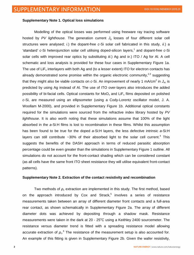
Supplementary Note 1. Optical loss simulations
Modelling of the optical losses was performed using freeware ray tracing software hosted by PV lighthouse. The generation current Jg losses of four different solar cell structures were analysed; i.) the dopant-free c-Si solar cell fabricated in this study, ii.) a ʻstandardʼ c-Si heterojunction solar cell utilising doped-silicon layers,1 and dopant-free c-Si solar cells with improved rear optics by substituting iii.) Ag and iv.) ITO / Ag for Al. A cell schematic and loss analysis is provided for these four cases in Supplementary Figure 1a. The use of LiFx interlayers with both Ag and (to a lesser extent) ITO for electron contacts has already demonstrated some promise within the organic electronic community,2,3 suggesting that they might also be viable contacts on c-Si. An improvement of nearly 1 mA/cm2 in Jsc is predicted by using Ag instead of Al. The use of ITO over-layers also introduces the added possibility of bi-facial cells. Optical constants for MoOx and LiFx films deposited on polished c-Si, are measured using an ellipsometer (using a Cody-Lorentz oscillator model, J. A. Woollam M-2000), and provided in Supplementary Figure 1b. Additional optical constants required for the simulations were sourced from the refractive index library hosted by PV lighthouse. It is also worth noting that these simulations assume that 100% of the light absorbed in the a-Si:H films is lost to recombination in these films. Whilst this assumption has been found to be true for the doped a-Si:H layers, the less defective intrinsic a-Si:H layers can still contribute ~30% of their absorbed light to the solar cell current.4 This suggests the benefits of the DASH approach in terms of reduced parasitic absorption percentage could be even greater than the simulations in Supplementary Figure 1 outline. All simulations do not account for the front-contact shading which can be considered constant (as all cells have the same front ITO sheet resistance they will utilise equivalent front-contact patterns).
Supplementary Note 2. Extraction of the contact resistivity and recombination
Two methods of ρc extraction are implemented in this study. The first method, based on the approach introduced by Cox and Strack,5 involves a series of resistance measurements taken between an array of different diameter front contacts and a full-area rear contact, as shown schematically in Supplementary Figure 2a. The array of different diameter dots was achieved by depositing through a shadow mask. Resistance measurements were taken in the dark at 20 - 25oC using a Keithley 2400 sourcemeter. The resistance versus diameter trend is fitted with a spreading resistance model allowing accurate extraction of ρc.6 The resistance of the measurement setup is also accounted for. An example of this fitting is given in Supplementary Figure 2b. Given the wafer resistivity,

NATURE ENERGY | www.nature.com/natureenergy 3
SUPPLEMENTARY INFORMATIONDOI: 10.1038/NENERGY.2015.31
thickness and estimated error in the measurement – the lower limit resolution for this technique is estimated at ~1 mΩcm2.
The second, simpler but less accurate method, is used to measure devices with ρc
values > 0.5 Ωcm2. The resistance between a full-area rear contact and a ~1.1 mm diameter front circular contact was measured and ρc was estimated by accounting for the expected bulk spreading resistance. It should be noted in both of the above contact structures that the extracted ρc comprises the interfacial resistivities and bulk resistivities of all layers in-between the c-Si and the outer Al layer. Reference samples with only Al contacts (no AMF interlayers) were also fabricated. These contacts exhibited rectifying behaviour when applied both directly and with passivating interlayers (TiOx and a-Si:H), such that ρc was prohibitively high for accurate extraction. In this case a lower limit estimation of ~5 Ωcm2 is made for these contacts.
The recombination at the direct c-Si(n) / LiFx / Al contact was investigated on planar, FZ, n-type (Nd ~ 5×1015cm-3) c-Si wafers coated symmetrically with a LiFx ~1.5 nm / Al ~15
nm stack. The Al layer is made thick enough to prevent oxidation of the entire layer at the same time as remaining thin enough to allow sufficient light through and not saturate the conductance signal of a photoconductance decay tester (Sinton WCT 120). The lifetime of these samples was too low for this tool to measure accurately, suggesting a high rate of surface recombination. To reduce this rate of surface recombination two candidate passivating layers, suitable for electron-selective heterocontacts when combined with the LiFx / Al contact. are a-Si:H(i) and TiOx films. When applied to c-Si both of these films present larger valence band than conduction band offsets potentially assisting in creating a preferential conductivity towards electrons. The Suns-implied Voc behaviour of the two samples are included in Supplementary Figure 3a showing 1 sun implied Voc values of 732 and 695 mV for the wafers coated with a-Si:H(i) and TiOx films, respectively (Sinton WCT 120). Due to the difference in wafer resistivity, recombination factors (J0) were extracted using different techniques7,8 for the a-Si:H(i) and TiOx coated wafers. Plots of J0 extractions of wafers coated with a-Si:H(i) and TiOx layers are included in Supplementary Figure 2b and c, respectively. It should be emphasised that the implied Voc and J0c values represent the recombination before LiFx / Al deposition and that some changes may occur after contact formation.
Supplementary Note 3. Optimum contact configuration simulations.
Simulations, similar to those in previous studies,9 are run using the freeware solar cell simulation program Quokka.10 Details of the unit cell characteristics and structure can be

4 NATURE ENERGY | www.nature.com/natureenergy
SUPPLEMENTARY INFORMATION DOI: 10.1038/NENERGY.2015.31
found in Supplementary Table 3. The two variables of the simulation are the rear contact ρc
and J0c. For every input ρc and J0c an optimum rear contact configuration is calculated by means of monitoring the device efficiency. Superimposed experimental data points can be matched with the points of these simulations to provide information on the optimum contact fraction and resultant efficiency which can be achieved. The results of this simulation are shown in Supplementary Figure 4. Experimental optimum ρc and J0c data for TiOx / LiFx / Al (purple triangle) and a-Si:H(i) / LiFx / Al (green square) contacts as well as the direct LiFx / Al (blue circle) contact (a J0 close to the diffusion limit is assumed11) are superimposed on this plot. For the interlayers it can be seen that both contacts are best applied in a 100% contact area and that devices with a-Si:H(i) interlayers have a higher idealised efficiency. It can also be seen that the direct LiFx / Al contact could be effectively applied in localised contacts (0.5% area) – an architecture which was previously not possible, given the aforementioned difficulties of contacting n-type c-Si.
Supplementary Note 4. Detailed DASH cell characterisation
The champion cell batch consisted of four 2 x 2 cm2 DASH cells, the light J-V results for these cells have been included in Supplementary Table 2, showing an average cell efficiency for the 4 cells above 19%. The small spread in results seen for each parameter is a testament to the exciting potential of this cell structure.
The champion cell was further characterised by measuring its light J-V behaviour at a range of illumination intensities (see Supplementary Figure 5a) and using the Suns-Voc
method (see Supplementary Figure 5b). The Voc values from the three light J-V curves in Supplementary Figure 5a are superimposed on the Suns-Voc curve showing a good correlation between the two methods. No large ʻbendingʼ or inflection points are seen in the Suns-Voc curve at high illumination intensities suggesting that there is no large unwanted Schottky barrier affecting the DASH cell.12 The Suns-Voc data was further used to construct an ideal pseudo J-V plot (see Supplementary Figure 5c) which reflects predicted behaviour of the DASH cell without the effect of parasitic series resistance. From a comparison between the cells pseudo and real J-V curves it can be seen that reducing the series resistance is an obvious path to higher efficiencies. The champion DASH cell light J-V is well fitted using a simple ʻone-diodeʼ model (also shown in Supplementary Figure 5c) with a series resistance Rs ~2.09 Ωcm2. A reduction of Rs to 1 Ωcm2 (a typical series resistance value for industrial c-Si solar cells) would increase the FF and η to above 79% and 21%, respectively.

NATURE ENERGY | www.nature.com/natureenergy 5
SUPPLEMENTARY INFORMATIONDOI: 10.1038/NENERGY.2015.31
The light J-V behaviour of the DASH cell was further characterised at a range of temperatures (see Supplementary Figure 5d). From these temperature dependent J-Vcurves an analysis of the Voc and FF temperature dependence for the DASH cell was conducted (see Supplementary Figure 5e) and compared to the behaviour of a SHJ cell (taken from Ref.13). The SHJ and DASH cells show largely similar behaviour exhibiting the expected decrease in Voc with temperature resulting in coefficients of -1.7 and -2 mV/oC, respectively. Similarly the FF evolution with temperature for both the SHJ and DASH cells has a negative gradient with values of -0.04 and -0.06 %/oC, respectively. Such similar temperature dependency of FF values suggests that DASH devices perform quite similarly to standard SHJ solar cells in terms of carrier transport.
The light J-V performance of a representative DASH cell was also measured before and after a ~10 minute, 100oC anneal without any significant change to the cell performance. This result is important given concerns associated with alkali metal ion incorporation in c-Si – centred around both the high mobility of ions and their tendency to form carrier recombination active defect levels within the c-Si bandgap.14 For the latter of these two points Li may be an exception as it has been shown by some authors to form a shallow donor level (even being used as an intentional dopant in some cases15). Regardless of this, the stability of the Voc before and after the anneal step suggests that Li incorporation is not an issue at these temperatures. The very high Voc also indicates that the well-known low temperature interaction between Al and a-Si:H,16 is prevented by the thin LiFx interlayer.
External quantum efficiency (EQE) analysis was also performed on the cells (in-house built set-up) accompanied by front surface reflectance measurements (Lambda 950, Perkin Elmer) to investigate the internal quantum efficiency. An estimation of the Jsc is found by integrating the product of the AM 1.5G spectrum (in photons /cm-2nm-1) and the EQE in the 310 – 1200 nm wavelength range. A Jsc of 39.4 mA/cm2 is calculated which, after correcting for a 5% reduction due to the contact fraction, agrees well with the light J-Vmeasured value of 37.07 mA/cm2.
To test the efficacy of the approach on both wafer doping types, simplified cells (1 × 1 cm2) without passivating interlayers were fabricated on n-type (Nd ~ 5×1015 cm-3) and p-type (Na ~ 7×1015 cm-3), planar, FZ wafers. A 15 nm MoOx hole contact was thermally evaporated on the front-side. This film was capped with a ~60 nm ITO film and a ~1 µm Cu front grid, both of which were sputtered (AJA International, ATC 1800 UHV) at room temperature through two different shadow masks to define the 1 × 1 cm2 cell area and front grid. The rear contact was formed by evaporating ~1.5 nm of LiFx followed by ~200 nm of Al without breaking vacuum. The light J-V characteristics of these cells was measured under

6 NATURE ENERGY | www.nature.com/natureenergy
SUPPLEMENTARY INFORMATION DOI: 10.1038/NENERGY.2015.31
standard conditions (AM 1.5G spectrum, 100 mW/cm2, ~25oC) and are provided in Supplementary Figure 5f. The top bus bar was excluded from the cell area for the current density calculation. Both cells exhibit efficiencies in excess of 10%, clearly indicating effective carrier separation. These results demonstrate the effectiveness of the DASH c-Si solar cell concept, irrespective of the substrate doping type (similar behaviour is also obtained for conventional doped a-Si:H SHJ cells1). This highlights a distinction between the DASH cells and the classic metal-insulator-silicon inversion layer (MIS-IL) cell architectures which also avoid the use of doped-silicon layers. The performance of the archetypal p-type MIS-IL cell is strongly linked to both the silicon wafer dopant type and concentration, mainly due to the need to form an Ohmic rear contact.

NATURE ENERGY | www.nature.com/natureenergy 7
SUPPLEMENTARY INFORMATIONDOI: 10.1038/NENERGY.2015.31
Supplementary Table 1 Loss mechanisms associated with doped-silicon.
Limitation Issue, consequence Cause Ref. Optical Parasitic free-carrier absorption,
reduces Jsc
High doping concentration 17
Parasitic window layer absorption, reduces Jsc
Using narrow gap window layers (eg. Doped a-Si:H and poly-Si)
4
Recombination Auger and radiative recombination, reduces Voc
High doping concentration 18
SRH recombination, reduces Voc
Dopant precipitates (eg. phosphorus clusters)
19
Dopant complexes (eg. Boron-oxygen defects)
20
Surface SRH recombination, reduces Voc
High surface dopant concentration (currently debated)
21
Bulk and surface recombination, reduces Voc
Band gap narrowing, increased minority carrier concentration
22
Transport Resistive losses, reduces FF(especially lateral Rs)
Dopant and carrier scattering, low majority carrier mobility
23
Low minority carrier diffusion length, reduces Jsc
Dopant and carrier scattering, low minority carrier mobility
23
Supplementary Table 2 High efficiency DASH cell results.
Voc (mV) Jsc (mA/cm2) FF ηCell1, Champion cell 716.4 37.07 73.15 19.42 Cell 2 716.5 36.97 71.84 19.03 Cell 3 716.7 37.02 71.26 18.91 Cell 4 716.4 37.07 71.1 18.88 Average of 4 cells 716.5 37.03 71.83 19.06
Supplementary Table 3 Assumptions and unit-cell characteristics of simulated cell.
Symbol Parameter Assumption / value J0front Front recombination factor 1 fA/cm2
τbulk Bulk lifetime Richter et. al. intrinsic lifetime18
Jg Generation current density ~44 mA/cm2
W Wafer thickness 160 µm ρbulk Bulk type, resistivity 1 Ωcm n-type J0rear Rear recombination factor (in non-contacted area) 1 fA/cm2
mfrear Rear line-contact metal fraction Finger width = variable, Finger pitch = 1000 µm

8 NATURE ENERGY | www.nature.com/natureenergy
SUPPLEMENTARY INFORMATION DOI: 10.1038/NENERGY.2015.31
Supplementary Figure 1. Generation current gain analysis. a, Simulations of the loss in
generation current for different heterocontact type c-Si solar cells. The simulations,
conducted using the wafer ray-tracer hosted by PVlighthouse.com, assume both surfaces of
a 200 µm wafer are random textured and coated with the films as indicated within the figure.
The mechanism and location of the current loss in each cell is broken down within each
column. b, Measured real (solid) and imaginary (dotted) refractive index values for the MoOx
(purple) and LiFx (blue) films.
a b

NATURE ENERGY | www.nature.com/natureenergy 9
SUPPLEMENTARY INFORMATIONDOI: 10.1038/NENERGY.2015.31
Supplementary Figure 2. Contact resistivity extraction. a, Schematic of the ρc test
structure. b, Exemplary measured and modelled resistance behaviour of a AMF / Al contact
to n-type c-Si.
a b

10 NATURE ENERGY | www.nature.com/natureenergy
SUPPLEMENTARY INFORMATION DOI: 10.1038/NENERGY.2015.31
Supplementary Figure 3. a-Si:H and TiOx interlayer passivation details a, Implied
SunsVoc behaviour for n-type silicon wafers symmetrically passivated with ~6nm of PECVD
a-Si:H(i) or ALD TiOx films. The dotted horizontal and vertical lines highlight the implied open
circuit voltages at 1 sun. Plots b, and c, show the measured and modelled lifetime behaviour
of n-type wafer coated symmetrically with a-Si:H(i) and TiOx films, respectively. The models
allow the extraction of surface recombination current pre-factors also provided in the plots.
a b c

NATURE ENERGY | www.nature.com/natureenergy 11
SUPPLEMENTARY INFORMATIONDOI: 10.1038/NENERGY.2015.31
Supplementary Figure 4. Optimum rear contact configuration simulations. Quokka
simulations of the optimum contact fraction (dotted lines) and resultant idealized efficiency
(coloured contours) as a function of the J0c and ρc. Values for the direct LiFx / Al contact
(blue circle) as well as the TiOx / LiFx / Al (purple triangle) and a-Si:H(i) / LiFx / Al contact
(green square) are superimposed on the plot.

12 NATURE ENERGY | www.nature.com/natureenergy
SUPPLEMENTARY INFORMATION DOI: 10.1038/NENERGY.2015.31
Supplementary Figure 5. Additional solar cell characterisation Light intensity
dependent a, J-V and; b, Voc behaviour (from Suns-Voc) of the DASH cell. The Suns-Voc is
also used to plot an ideal pseudo J-V curve for the DASH cell in c, which is compared to the
real DASH cell light J-V and a simple ʻone-diodeʼ fit of the real light J-V data. d, shows the
temperature dependent (16 - 65oC) light J-V behaviour of a standard DASH cell measured
under 1 sun conditions; and e, compares the voltage and fill factor temperature dependence
of DASH and SHJ type cells. f, Light J-V and cell characteristics measured under standard 1
sun conditions of basic n and p-type DASH cells without a-Si:H(i) passivating interlayers
showing that effective carrier separation can be achieved regardless of the base wafer
doping.
a b c
d e f

NATURE ENERGY | www.nature.com/natureenergy 13
SUPPLEMENTARY INFORMATIONDOI: 10.1038/NENERGY.2015.31
Supplementary References
1. Descoeudres, A. et al. >21%; Efficient Silicon Heterojunction Solar Cells on n- and p-Type
Wafers Compared. Photovolt. IEEE J. Of 3, 83–89 (2013).
2. Wang, X. J. et al. Enhancement of electron injection in organic light-emitting devices
using an Ag/LiF cathode. J. Appl. Phys. 95, 3828–3830 (2004).
3. Sakai, J. et al. Efficient organic photovoltaic tandem cells with novel transparent
conductive oxide interlayer and poly (3-hexylthiophene): Fullerene active layers. Sol.
Energy Mater. Sol. Cells 94, 376–380 (2010).
4. Holman, Z. C. et al. Current Losses at the Front of Silicon Heterojunction Solar Cells.
Photovolt. IEEE J. Of 2, 7–15 (2012).
5. Cox, R. H. & Strack, H. Ohmic contacts for GaAs devices. Solid-State Electron. 10, 1213
– 1218 (1967).
6. Cohen, S. S. Contact resistance and methods for its determination. Thin Solid Films 104,
361 – 379 (1983).
7. D.E. Kane & Swanson, R. M. Measurement of the Emitter Saturation Current by a
Contactless Photoconductivity Decay Method. in Proc of the 18th IEEE Photovoltaic
Specialists Conference 578–583 (1985).
8. Cuevas, A. The effect of emitter recombination on the effective lifetime of silicon wafers.
Sol. Energy Mater. Sol. Cells 57, 277 – 290 (1999).
9. Bullock, J. et al. Amorphous silicon enhanced metal-insulator-semiconductor contacts for
silicon solar cells. J. Appl. Phys. 116, 163706, (2014).
10. Fell, A. A Free and Fast Three-Dimensional/Two-Dimensional Solar Cell Simulator
Featuring Conductive Boundary and Quasi-Neutrality Approximations. Electron Devices
IEEE Trans. On 60, 733–738 (2013).
11. Mader, C., Muller, J., Eidelloth, S. & Brendel, R. Local rear contacts to silicon solar
cells by in-line high-rate evaporation of aluminum. Sol. Energy Mater. Sol. Cells 107, 272
– 282 (2012).

14 NATURE ENERGY | www.nature.com/natureenergy
SUPPLEMENTARY INFORMATION DOI: 10.1038/NENERGY.2015.31
12. Glunz, S. W., Mackel, H., Nekarda, J. & Cuevas, A. Analyzing back contacts of
silicon solar cells by Suns-Voc-measurements at high illumination densities. in 22nd
European Photovoltaic Solar Energy Conference and Exhibition (2007).
13. Battaglia, C. et al. Silicon heterojunction solar cell with passivated hole selective
MoOx contact. Appl. Phys. Lett. 104, 113902 (2014).
14. Chen, J. W. & Milnes, A. G. Energy Levels in Silicon. Annu. Rev. Mater. Sci. 10,
157–228 (1980).
15. Wysocki, J. J. Lithium-doped radiation resistant silicon solar cells. in Electron
Devices Meeting, 1966 International 12, 24–26 (1966).
16. Bullock, J. et al. Amorphous silicon passivated contacts for diffused junction silicon
solar cells. J. Appl. Phys. 115, 163703, (2014).
17. Baker-Finch, S. C., McIntosh, K. R., Yan, D., Fong, K. C. & Kho, T. C. Near-infrared
free carrier absorption in heavily doped silicon. J. Appl. Phys. 116, 063106, (2014).
18. Richter, A., Glunz, S. W., Werner, F., Schmidt, J. & Cuevas, A. Improved quantitative
description of Auger recombination in crystalline silicon. Phys. Rev. B 86, 165202 (2012).
19. Min, B. et al. Heavily doped Si:P emitters of crystalline Si solar cells: recombination
due to phosphorus precipitation. Phys. Status Solidi RRL Rapid Res. Lett. 8, 680–684
(2014).
20. Schmidt, J. & Cuevas, A. Electronic properties of light-induced recombination centers
in boron-doped Czochralski silicon. J. Appl. Phys. 86, 3175–3180 (1999).
21. King, R. R., Sinton, R. A. & Swanson, R. M. Studies of diffused phosphorus emitters:
saturation current, surface recombination velocity, and quantum efficiency. Electron
Devices IEEE Trans. On 37, 365–371 (1990).
22. Yan, D. & Cuevas, A. Empirical determination of the energy band gap narrowing in
p+ silicon heavily doped with boron. J. Appl. Phys. 116, 194505, (2014).
23. Klaassen, D. B. M. A unified mobility model for device simulation: Model equations
and concentration dependence. Solid-State Electron. 35, 953 – 959 (1992).