EFFECTS OF WELDING METHODS ON THE STRUCTURAL …
14
U.P.B. Sci. Bull., Series D, Vol. 83, Iss. 2, 2021 ISSN 1454-2358 EFFECTS OF WELDING METHODS ON THE STRUCTURAL PROPERTIES OF AUSTENITIC STAINLESS STEEL - X2CrNiMo 17-12-2 PIPES REPAIRED BY WELDING Florina IONESCU 1 , Gheorghe SOLOMON 2 , Delia GÂRLEANU 3 , Gabriel GÂRLEANU 4 and Ion Mihai VASILE 5 The article presents an experiment of welding an austenitic steel. The main purpose of the research is to elaborate new welding technologies for the spiral heat exchangers repairing, where the accessibility is low and difficult. Experimental program was performed by realization of welded mini-seams on the areas where an artificial defect was processed (holes with diameters of 2, 3 and 4 mm, respectively) inside pipes with a diameter of 42 mm and wall thickness of 3 mm. In order to establish the shape of the defects and the analysis of the areas in which they appeared, cross-sections were performed, then the samples were analyzed by optical and electron microscopy. Keywords: microstructure, WIG welding, reconditioning by welding, stainless steel 1. Introduction Nowadays the austenitic stainless steels are used in environments where a high level of corrosion resistance is required and in severe conditions with very high temperatures, due to its corrosion resistance and due to the fact that it retains its mechanical properties at high temperatures [1-4]. When welding austenitic stainless steel using conventional fusion welding processes, such as GTAW, TIG, GMAW and laser welding a series of limitations can occur [2, 3, 5, 12]: • loss of nitrogen by desorption of nitrogen or formation of nitrogen associated pore in the weld zone, • precipitation of Cr-nitrides and carbides in weld zone and heat-affected zone (HAZ), • solidification cracks in weld zone and liquation cracks in the HAZ. 1 PhD student, Dept. of Quality Engineering and Industrial Technologies, University POLITEHNICA of Bucharest, Romania, e-mail: [email protected] 2 Professor, Dept. of Quality Engineering and Industrial Technologies, University POLITEHNICA of Bucharest, Romania, e-mail: [email protected] 3 Associate Professor, Dept. Of Quality Engineering and Industrial Technologies, University POLITEHNICA of Bucharest, Romania, e-mail: [email protected] 4 Associate Professor, Dept. Of Quality Engineering and Industrial Technologies, University POLITEHNICA of Bucharest, Romania, e-mail: [email protected] 5 Lecturer, Dept. Of Quality Engineering and Industrial Technologies, University POLITEHNICA of Bucharest, Romania, e-mail: [email protected]
Transcript of EFFECTS OF WELDING METHODS ON THE STRUCTURAL …

U.P.B. Sci. Bull., Series D, Vol. 83, Iss. 2, 2021 ISSN 1454-2358
EFFECTS OF WELDING METHODS ON THE STRUCTURAL PROPERTIES OF AUSTENITIC STAINLESS STEEL - X2CrNiMo 17-12-2 PIPES REPAIRED BY WELDING
Florina IONESCU1, Gheorghe SOLOMON2, Delia GÂRLEANU3, Gabriel GÂRLEANU4 and Ion Mihai VASILE5
The article presents an experiment of welding an austenitic steel. The main purpose of the research is to elaborate new welding technologies for the spiral heat exchangers repairing, where the accessibility is low and difficult. Experimental program was performed by realization of welded mini-seams on the areas where an artificial defect was processed (holes with diameters of 2, 3 and 4 mm, respectively) inside pipes with a diameter of 42 mm and wall thickness of 3 mm. In order to establish the shape of the defects and the analysis of the areas in which they appeared, cross-sections were performed, then the samples were analyzed by optical and electron microscopy.
Keywords: microstructure, WIG welding, reconditioning by welding, stainless steel
1. Introduction Nowadays the austenitic stainless steels are used in environments where a
high level of corrosion resistance is required and in severe conditions with very high temperatures, due to its corrosion resistance and due to the fact that it retains its mechanical properties at high temperatures [1-4].
When welding austenitic stainless steel using conventional fusion welding processes, such as GTAW, TIG, GMAW and laser welding a series of limitations can occur [2, 3, 5, 12]:
• loss of nitrogen by desorption of nitrogen or formation of nitrogen associated pore in the weld zone,
• precipitation of Cr-nitrides and carbides in weld zone and heat-affected zone (HAZ),
• solidification cracks in weld zone and liquation cracks in the HAZ.
1 PhD student, Dept. of Quality Engineering and Industrial Technologies, University POLITEHNICA of Bucharest, Romania, e-mail: [email protected] 2 Professor, Dept. of Quality Engineering and Industrial Technologies, University POLITEHNICA of Bucharest, Romania, e-mail: [email protected] 3 Associate Professor, Dept. Of Quality Engineering and Industrial Technologies, University POLITEHNICA of Bucharest, Romania, e-mail: [email protected] 4 Associate Professor, Dept. Of Quality Engineering and Industrial Technologies, University POLITEHNICA of Bucharest, Romania, e-mail: [email protected] 5 Lecturer, Dept. Of Quality Engineering and Industrial Technologies, University POLITEHNICA of Bucharest, Romania, e-mail: [email protected]

236 Florina Ionescu, Gheorghe Solomon, Delia Gârleanu, Gabriel Gârleanu And Ion Mihai Vasile
One of the applications of the austenitic stainless steel is the constructions of the heat exchangers. To ensure safety, reliability and proper operation, the attention to the material must start from the design phase and must continue in manufacturing, installation, operation and maintenance [6-9].
Usually, most defects are located on the sheets (turns) towards the center of the heat exchanger, where the peripheral speed increases greatly, due to the decrease in the diameter of the coil. The beginning coil has a diameter of approximately 1 m and the end one 0.3 m, which means an increase of almost 3 times the peripheral flow velocity with major implications on the cavitation phenomenon [6, 11].
This paper presents some of the effects of a new repair by welding technologies on the welded seam microstructure of austenitic stainless steel.
Objective
The main objective of the experiments conducted was to analyze a repair technology by welding of heat exchangers, where accessibility to the site of defects is extremely difficult, requiring special devices to ensure access to narrow areas over limited lengths.
2. Materials and methods
In order to conduct the experiments, there were used the following materials:
• X2CrNiMo 17-12-2 stainless steel pipes; • Austenitic stainless steel wire filler material brand OK Tigrod
316L. The chemical composition of the basic material and of the filler material is
presented in table 1, and in table 2 are presented the mechanical properties of both steels [10].
Table 1 Chemical composition of the basic material and filler material
Material Chemical composition
C [%]
Mn [%]
P [%]
S [%]
Si [%]
Cr [%]
Ni [%]
Mo [%]
N [%]
Cu [%]
Other [%]
X2CrNiMo 17-12-2
EN ISO 10088-2 0.03 2 0.045 0.03 0.75 16 -
18 10 - 14 2 - 3 0.10 - -
OK Tigrod 316L Max. 0.03
1-2.5 - - 0.3-
0.65 18-20
11-14 2-3 0.08 - -
Effects of welding methods on the struct. […] - X2CrNiMo17-12-2 pipes repaired by welding 237
Table 2 Mechanical properties of basic material and filler material
Material Mechanical properties Tensile strength [MPa]
Yield strength [MPa]
Elongation (% at50 mm)
[min, %]
Hardness Brinell Rockwell B
X2CrNiMo 17-12-2 EN ISO 10088-2 485 170 40 217 95
OK Tigrod 316L 600 470 32 - - Design and realization of test probes
In order to validate the welding repair technology, an experimental program was developed for the realization of welded mini-seams on the areas where an artificial defect was processed (holes with diameters of 2, 3 and 4 mm, respectively) inside pipes with a diameter of 42 mm and wall thickness of 3 mm.
The holes were drilled at different distances from the access end of the WIG welding gun, respectively at 50 mm, 100 mm, 150 mm and 200 mm, the total length of the pipe being 250 mm. The experimental WIG repairing process can be observed in figure 1 and one example of the test probes obtained can be observed in figure 2.
Fig. 1. Welding repair of the samples
Fig. 2. One example of the test probes obtained after WIG repair (probe 1)
The dimensions of the samples prepared for destructive examination is summarized in table 3.
Table 3 Samples prepared for destructive examination
Sample code Analyzed areas
1 - 50 mm 2 – 100 mm 3 – 150 mm 4 – 200 mm
1 2mm holes MB, HAZ ,
Welded seam
MB, HAZ , Welded seam
MB, HAZ , Welded seam
MB, HAZ , Welded seam

238 Florina Ionescu, Gheorghe Solomon, Delia Gârleanu, Gabriel Gârleanu And Ion Mihai Vasile
2 3mm holes MB, HAZ , Welded seam
MB, HAZ , Welded seam
MB, HAZ , Welded seam
MB, HAZ , Welded seam
3 4mm holes MB, HAZ , Welded seam
MB, HAZ , Welded seam
MB, HAZ , Welded seam
MB, HAZ , Welded seam
The results obtained from the non-destructive tests showed the formation of imperfections in the areas of the mini-welds made on the processed holes, these being inherent in a limited experimental program. In order to establish the shape of the defects and the analysis of the areas in which they appeared, cross-sections were performed by experimental welding, then the samples were analyzed by optical and electron microscopy.
Sample preparation The preparation of the samples consisted in completing the following steps: The embedding of the samples was done in phenolic resin. The samples
obtained are shown in figures 3 and 4.
Fig. 3. Sample 1 (1x)- positioning of the welding
spots 1.1. – welding spot 1 - 50 mm; 1.2 - welding spot 2 – 100 mm; 1.3. - welding spot 3 - 150 mm; 1.4
- welding spot 4 - 200 mm
Fig. 4. Sample 2 (1x) - positioning of the welding spots
1.1. - welding spot 1 - 50 mm; 1.2 - welding spot 2 – 100 mm; 1.3. - welding spot 3 - 150
mm; 1.4 - welding spot 4 - 200 mm
The polishing of the samples was done manually using the following materials:

Effects of welding methods on the struct. […] - X2CrNiMo17-12-2 pipes repaired by welding 239
o The grinding of the samples was performed manually using abrasive grit of 360, 500 and 1000;
o The polishing of the samples was done manually with Topol 3 solution. The samples obtained after polishing are shown in figures 5 and 6, respectively.
Fig. 5. Sample 1 (1x) - image obtained after
polishing
Fig. 6. Sample 2 (1x) - image obtained after
polishing Royal water consisting of 3 parts HCl and one-part HNO3 was used to attack the samples.
3. Results and discussion
3.1. Optical analysis The microscopic analysis was made in accordance with the prescription of the standards SR EN 1321:2000, STAS 7626-79 and CR 12361:1996 + AC: 1997, using an Olympus GX51 microscope equipped with AnalySis software specialized for image processing. Measurement conditions: Temperature +26°C (reference temperature +23°C±5°C); Moisture 42%.
The results of the microscopic analysis are presented as follows: In figure 7 it is presented the basic material structure; Sample 1 - circular defects, Φ2 mm hole diameter disposed as follows: o Welding spot 1 - 50 mm distance from the WIG gun access point (figures 8
and 9); o Welding spot 2 - 100 mm distance from the WIG gun access point (figures
10 and 11); o Welding spot 3 - 150 mm distance from the WIG gun access point (figures
12 and 13);
240 Florina Ionescu, Gheorghe Solomon, Delia Gârleanu, Gabriel Gârleanu And Ion Mihai Vasile
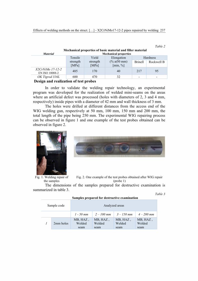
o Welding spot 4 - 200 mm distance from the WIG gun access point (figures 14 and 15);
Sample 2 - circular defects, Φ3 mm hole diameter disposed as follows: o Welding spot 1 - 50 mm distance from the WIG gun access point (figures 16
and 17); o Welding spot 2 - 100 mm distance from the WIG gun access point (figures
18 and 19); o Welding spot 3 - 150 mm distance from the WIG gun access point (figures
20 and 21); o Welding spot 4- 200 mm distance from the WIG gun access point (figures
22 and 23).
Fig. 7. Basic material (200x)
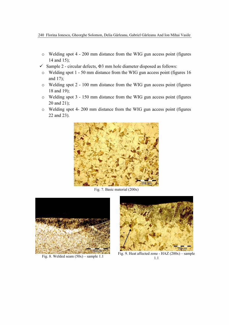
Fig. 8. Welded seam (50x) – sample 1.1
Fig. 9. Heat affected zone - HAZ (200x) – sample
1.1

Effects of welding methods on the struct. […] - X2CrNiMo17-12-2 pipes repaired by welding 241
Fig. 10. Welded seam – final layer (100x) – sample
1.2
Fig. 11. Root area (50x) – sample 1.2
Fig. 12. Welded seam(1000x) - sample 1.3
Fig. 13. Heat-affected zone - HAZ (500x) – sample
1.3
Fig. 14. Welded seam (1000x) – sample 1.4
Fig. 15. Heat-affected zone - HAZ (500x) – sample
1.4

242 Florina Ionescu, Gheorghe Solomon, Delia Gârleanu, Gabriel Gârleanu And Ion Mihai Vasile
Figure 7 shows the structure of the basic material - austenite (twinned polyhedral grains) and ferrite delta - about 5%. The diameter of the grains is about 20µm.
The welding was performed in two passes, with an overlap of about 500 µm, to ensure the complete penetration and melting of the filler material, with the complete filling of the 2 mm hole (figure 8). The weld has no overhang, the upper molten area being at the surface of the base material. In the root area is observed the area of thermo-mechanical influence (light in color) with a width of about 200 µm. On the analyzed area, the weld is well formed and without discontinuities.
The heat affected zone (see figure 9) has an overheating area with an increase in granulation, with coarse polyhedral grains with a maximum diameter of 58 µm.
In figure 10 the final layer of the welded seam has a height of 852 µm and a width of 3106 µm. The connection area with the main seam has an acicular microstructure.
The main area of the welded seam (see figure 11) shows an austenite dendrites structure and delta ferrite with inter-dendritic precipitation. The grains are elongated in the direction of heat flow. The area of thermo-mechanical influence has large granulation. In figure 12 it can be observed a dendritic microstructure of austenite and ferrite delta. When the welding current increases the tendency of the molten metal to leak appears and different defects like pores and segregations are formed. In the weld also the proportion of ferrite delta increases. This mentioned aspect is not desirable, because the percentage of ferrite that ensures the best conditions of crack resistance is in the range of 5-8%.
Fig. 16. Welded seam (500x) – sample 2.1
Fig. 17. Heat affected zone - HAZ (500x) – sample
2.1

Effects of welding methods on the struct. […] - X2CrNiMo17-12-2 pipes repaired by welding 243
Fig. 18. Welded seam (500x) - sample 2.2
Fig. 19. Heat affected zone– HAZ (200x) - sample
2.2
Fig. 20. Macroscopic view of the welded
seam (50x) - sample 2.3
Fig. 21. Heat affected zone– HAZ (500x) – sample
2.3
Fig. 22. Welded seam (500x) - sample 2.4
Fig. 23. Heat affected zone– HAZ (500x) – sample
2.4 Figure 16 shows a lack of melting at the root of the weld and metal
overlap. According to the SR EN 6520 standard, the lack of melting or incomplete melting is defined as the lack of connection between the deposited metal and the base metal or between the two successive layers of deposited metal. It has the

244 Florina Ionescu, Gheorghe Solomon, Delia Gârleanu, Gabriel Gârleanu And Ion Mihai Vasile
defect code 401 and the specific code for the lack of root melting is the code 4013.
According to the ISO 5817 standard this type of defect is not allowed. The main causes of this defect are the use of too low welding current, too fast feed rate, improper cleaning of materials, improper joint geometry, use of an electrode with too large diameter and improper position and incorrect handling of the electrode.
Analyzing figure 17 in the root area of the weld was identified a crack developed from the inclusion at the top of the weld. Cracks are considered a dangerous defect and are not allowed. It can be defined as a discontinuity of material, having an elongated shape, a very small radius of curvature in the tip area and an opening between its flanks.
Among the main causes of cracks in welded joints are the chemical-mechanical incompatibility between the filler material and the base material, the use of too low welding current, the use of a high cooling rate, the excess participation of the base metal in the formation of the seam, lack of preheating or insufficient preheating temperature.
3.2. SEM analysis Examination by SEM analysis (Scanning electron microscopy) was performed according to the standards SR EN 1321:2001, STAS 7626-79 and the UPB-PO-05.03.02 measurement procedure.
The vacuum system features (FEI Company patent) include a patented technology of differential pumping of electromagnetic lenses (ESEM), the use of a turbo-molecular pump with a flow rate of 70 l / s and a rotary pump for preliminary vacuum.
The system allows a continuous transition between working modes (continuous transition from Low Vacuum to High Vacuum and vice versa). Due to the vacuum system particularities, the gases or dirt from the sample do not reach the filament area because they are sucked in the lower part of the column on a separate path.
As a result, the column always remains in the advanced vacuum during the analysis, while in the sample chamber the vacuum level can be chosen as needed. In this way, the possibility of soiling the openings inside the column is very low and, as such, the maintenance of the system is much simplified.
The results obtained for sample 1.1 are presented in figures 24 ÷ 26, and for sample 1.2 are presented in figures 27 ÷ 29.

Effects of welding methods on the struct. […] - X2CrNiMo17-12-2 pipes repaired by welding 245
Fig. 24. Base material (2000x) - sample1.1
Fig. 25. Welded seam (5000x) - Austenite - dendritic microstructure and fine films of inter-granular delta
ferrite – sample1.1
Fig. 26. Micro-zone analysis of the base material (on the delta ferrite islands) – sample 1.1
The base material is an austenitic stainless steel, characterized by the polyhedral microstructure of austenite with sliding planes of specific atomic blocks (twins). On the boundaries of the austenite grains, the presence of the delta ferrite, in the form of elongated islands, of a lighter color in relation to the crystalline austenite grains, is observed.

246 Florina Ionescu, Gheorghe Solomon, Delia Gârleanu, Gabriel Gârleanu And Ion Mihai Vasile
Fig. 27. Welded seam (50x) – sample 1.2
Fig. 28. Welded seam (5000x) Austenite, ferrite and martensite structure - sample 1.2
Fig. 29. Welded seam sample 1.2 (1000x)
Conclusions Generally, the cross-sectional appearance of the probes welding is correct
in terms of geometric shape (uniform elevation, no pores, craters or notches), the connection to the surface of the base material (smooth passage without discontinuities) and the microstructure of the

Effects of welding methods on the struct. […] - X2CrNiMo17-12-2 pipes repaired by welding 247
characteristic areas of the joint (seam, heat-affected zone, fusion line). There is a good, continuous and flawless interface between the weld and the base material.
Particularly, there were identified defects like lack of melting at the root of the weld and a crack developed from the inclusion at the top of the weld.
If the weld is placed at a greater depth, the correct welding geometry is more difficult to obtain.
By increasing the value of the welding current, the molten metal leaks at the root of the weld, several pores appear and the lack of adhesion to the base metal can be obtained.
The proportion of delta ferrite in welding is increased. This aspect is not desirable because the percentage of ferrite that ensures the best conditions of crack resistance is NF = 5-8%.
R E F E R E N C E S
[1]. Zhuqing Wanga, Todd A. Palmerab, Allison M. Beesea, Effect of processing parameters on microstructure and tensile properties of austenitic stainless steel 304L made by directed energy deposition additive manufacturing, Journal Acta Materialia 110, pg. 226 – 235, 2016.
[2]. H.B. Li, Z.H. Jiang, H. Feng, S.C. Zhang, L. Li, P.D. Han, R.D.K. Misra, J.Z. Li, Microstructure, mechanical and corrosion properties of friction stir welded high nitrogen nickel-free austenitic stainless steel, Journal Materials and Design Vol. 84, pg. 291–299, 2015.
[3]. A. Mortezaie, M. Shamanian, An assessment of microstructure, mechanical properties and corrosion resistance of dissimilar welds between Inconel 718 and 310S austenitic stainless steel, International Journal of Pressure Vessels and Piping Vol. 116, pg. 37-46, 2014.
[4]. J. N. Dupont, S. W. Banovic, AND A. R. Marder, Microstructural Evolution and Weldability of Dissimilar Welds between a Super Austenitic Stainless Steel and Nickel-Based Alloys, Supplement to the Welding Journal, JUNE 2003.
[5]. M. Sireeshaa, V. Shankarb Shaju, K. Albertb, S. Sundaresana, Microstructural features of dissimilar welds between 316LN austenitic stainless steel and alloy 800, Materials Science and Engineering: A, Volume 292, Issue 1, Pages 74-82, 15 November 2000.
[6]. F Ionescu, Ghe Solomon, G Gârleanu, D Gârleanu and MC Dijmărescu, Reconditioning by Welding of the Spiral Heat Exchangers Made of Austenitic Stainless Steel - X2CrNiMo 17-12-2, ModTech 2020, IOP Conf. Series: Materials Science and Engineering 916, 2020.
[7]. B. Mvola, P. Kah, J. Martikainen, Dissimilar ferrous metal welding using advanced gas metal arc welding processes, Rev. Adv. Mater. Sci. 38, 125-137, 2014.
[8]. E. Ranjbarnodeh, M. Pouranvari, A. Fischer, Influence of welding parameters on residual stresses in dissimilar HSLA steels welds, Metall. Mater. Eng. 19, 2013.
[9]. GS. Kou, Welding metallurgy, second ed., John Wiley&Sons, Inc., Hoboken, New Jersey, 2003.
[10]. EN 10088-2: 2005 Stainless steels. Technical delivery conditions for sheet/plate and strip of corrosion resisting steels for general purposes;

248 Florina Ionescu, Gheorghe Solomon, Delia Gârleanu, Gabriel Gârleanu And Ion Mihai Vasile
[11]. A 240/A 240M:2004 - Standard Specification for Chromium and Chromium-Nickel Stainless Steel Plate, Sheet, and Strip for Pressure Vessels and for General Applications, ASTM International).
[12]. SR EN 1011/1:2004 - Welding. Recommendations for welding of metallic materials. Part 1: General guidance for arc welding.