Effects of Water Droplets on the Numerical Simulation of a ...
8
*Corresponding Author )Vol. 21 (No. 1) / 7 International Journal of Thermodynamics(IJoT) Vol. 21 (No. 1), pp. 7-14, 2018 ISSN 1301-9724 / e-ISSN 2146-1511 doi: 10.5541/ijot.308766 www.ijoticat.com Published online: March 1, 2018 Effects of Water Droplets on the Numerical Simulation of a Complete Gas Turbine G.K. Dayyabu 1 , 2, a* , Q. Zheng 1,b , H .Zhang 1,c , L. Sun¹ ,d 1, 2 College of Power and Energy, Harbin Engineering University, China 2 Department of Mechanical Engineering, Hassan Usman Katsina Polytechnic, 820001 Katsina, Nigeria Corresponding author: a [email protected] Received 25 April 2017, Accepted 08 February 2018 Abstract Numerical simulation of a complete gas turbine engine working with inlet wet injection has been evaluated using computational fluid dynamic (CFD), the effects of water droplet and injection rate on the compressor operation, engine combustion and the turbine were studied. The results obtained in contrast with dry compression unveil that, with minimum amount of water droplet and high water injection rate (0.5% - 3.0%) there is potential influence on the engine performance, it boost the amount of inlet mass flow rate, raises compression and expansion pressure ratio, uplift engine thrust and thermal efficiency through absorption of heat and radiation intensity emission, decreases the relative specific fuel consumption, combustion and turbine outlet temperature and cuts down the amount of NOx production. Keywords: Wet compression; gas turbine; water injection rate; NOx production. 1. Introduction Numerical simulation and experimental study research of the exhaust gas injection of a gas turbine has been done with propose of additional diversion bell mouth to the mixing section entrance. The experiments validate the numerical simulation results, and the tally situation is good [1]. In the last few decades, the advent of new and more stringent regulations on gas emission for stationary power systems ratified, the EPA promulgated revised new source performance standards (NSPS) for stationary combustion turbines applicable to stationary combustion turbines[2]. Gas turbines based on dry low Nox (DLN) burners of various manufacturers are now demonstrating NOx and CO levels below 10 ppm[3]. In many applications the old generation gas turbines, still based on conventional diffusion flame burners, are run with various unconventional fuels not fully compatible with modern lean-premix flame mode[4]. The new design improves the performance by changing transitional form of nozzle and its angular size. Meanwhile, the performance of the design has been predicted and the structure has been optimized by CFD method [5]. The effort to establish allowable levels of engine exhaust pollutants was begun by the United States Environmental Protection Agency, EPA. Numerous studies of ambient air quality in and around various airports were conducted[6]. Effects on the thermodynamic properties were thoroughly analyzed for different parameters such as compression speeds and overspray[7]. Any possible improvements of the performance of the gas turbine engines would help to minimize the worlds annual fossil fuel consumption and hence the emissions of the adverse greenhouse gasses[8]. Evaluation and measure of the appropriate parameters that describe the engine modes during changes of the exhaust nozzle diameter were studied, investigation the adaption of different performance maps of centrifugal compressors driven by dual-shaft gas turbines during operation was carried out, estimation of compressor, gas turbine and combined efficiency are considered [9]. Economic analysis of heavy duty industrial gas turbine plant has been investigated using a specified model[10]. The tip leakage vortex in the blade passage becomes closer to the blade suction surface, resulting in an increase of the heat transfer coefficient [11]. An analogy between different cooling systems was set up on computer simulation model, performance characteristic were analyzed and the results show evaporation is more economically than cooling coil system in refrigeration unit [12]. In modelling of combustor, it conclude that wet cycle gas turbines possess higher number of full load equivalent operating hours and can fetch higher investment payback with minimum limitation to their overall environmental performance [13]. Similarly, one of the most frequent solutions to the performance of an industrial gas turbine can be using the humidified gas turbines, a phenomenal by which water or steam is sprayed at different positions on the system to boost out the power[14]. In the face of the constant consumption of the earth's energy, increasing the utilization rate of the fuel, increasing the efficiency of the engine has become an important goal for the scientific research workers in the gas turbine industry [15, 16]. Their results show that, water injection is not only a technique to improved thermodynamics performance, but also a method to stabilize the compression system when it approaches stall [17, 18]. Among the motives of wet compression is moving towards isothermal compression from adiabatic compression [19]. Details analysis on evaluation stage-by-stage compressor performance with water injection is by using the stage-stacking method [20, 21]. The heat transfer mostly rely on the geometry of the fin like length, thickness, cross sectional area, width, spacing between the fins [22]. More than 1000 gas turbines with inlet cooling presently installed [23]. For each 5ºC decrease of inlet air temperature, net
Transcript of Effects of Water Droplets on the Numerical Simulation of a ...

*Corresponding Author )Vol. 21 (No. 1) / 7
International Journal of Thermodynamics(IJoT) Vol. 21 (No. 1), pp. 7-14, 2018 ISSN 1301-9724 / e-ISSN 2146-1511 doi: 10.5541/ijot.308766 www.ijoticat.com Published online: March 1, 2018
Effects of Water Droplets on the Numerical Simulation of a Complete Gas Turbine
G.K. Dayyabu 1 , 2, a*, Q. Zheng1,b , H .Zhang1,c , L. Sun¹,d
1, 2 College of Power and Energy, Harbin Engineering University, China 2 Department of Mechanical Engineering, Hassan Usman Katsina Polytechnic, 820001 Katsina, Nigeria
Corresponding author: a [email protected]
Received 25 April 2017, Accepted 08 February 2018
Abstract
Numerical simulation of a complete gas turbine engine working with inlet wet injection has been evaluated using
computational fluid dynamic (CFD), the effects of water droplet and injection rate on the compressor operation, engine
combustion and the turbine were studied. The results obtained in contrast with dry compression unveil that, with
minimum amount of water droplet and high water injection rate (0.5% - 3.0%) there is potential influence on the
engine performance, it boost the amount of inlet mass flow rate, raises compression and expansion pressure ratio,
uplift engine thrust and thermal efficiency through absorption of heat and radiation intensity emission, decreases the
relative specific fuel consumption, combustion and turbine outlet temperature and cuts down the amount of NOx
production.
Keywords: Wet compression; gas turbine; water injection rate; NOx production.
1. Introduction
Numerical simulation and experimental study research of
the exhaust gas injection of a gas turbine has been done with
propose of additional diversion bell mouth to the mixing
section entrance. The experiments validate the numerical
simulation results, and the tally situation is good [1]. In the
last few decades, the advent of new and more stringent
regulations on gas emission for stationary power systems
ratified, the EPA promulgated revised new source
performance standards (NSPS) for stationary combustion
turbines applicable to stationary combustion turbines[2]. Gas
turbines based on dry low Nox (DLN) burners of various
manufacturers are now demonstrating NOx and CO levels
below 10 ppm[3]. In many applications the old generation
gas turbines, still based on conventional diffusion flame
burners, are run with various unconventional fuels not fully
compatible with modern lean-premix flame mode[4]. The
new design improves the performance by changing
transitional form of nozzle and its angular size. Meanwhile,
the performance of the design has been predicted and the
structure has been optimized by CFD method [5].
The effort to establish allowable levels of engine exhaust pollutants was begun by the United States
Environmental Protection Agency, EPA. Numerous studies
of ambient air quality in and around various airports were
conducted[6]. Effects on the thermodynamic properties were
thoroughly analyzed for different parameters such as
compression speeds and overspray[7]. Any possible
improvements of the performance of the gas turbine engines
would help to minimize the worlds annual fossil fuel
consumption and hence the emissions of the adverse
greenhouse gasses[8]. Evaluation and measure of the
appropriate parameters that describe the engine modes
during changes of the exhaust nozzle diameter were studied,
investigation the adaption of different performance maps of
centrifugal compressors driven by dual-shaft gas turbines
during operation was carried out, estimation of compressor,
gas turbine and combined efficiency are considered [9].
Economic analysis of heavy duty industrial gas turbine plant
has been investigated using a specified model[10]. The tip
leakage vortex in the blade passage becomes closer to the
blade suction surface, resulting in an increase of the heat
transfer coefficient [11]. An analogy between different
cooling systems was set up on computer simulation model,
performance characteristic were analyzed and the results
show evaporation is more economically than cooling coil
system in refrigeration unit [12]. In modelling of combustor,
it conclude that wet cycle gas turbines possess higher number
of full load equivalent operating hours and can fetch higher
investment payback with minimum limitation to their
overall environmental performance [13]. Similarly, one of
the most frequent solutions to the performance of an
industrial gas turbine can be using the humidified gas
turbines, a phenomenal by which water or steam is sprayed
at different positions on the system to boost out the
power[14]. In the face of the constant consumption of the
earth's energy, increasing the utilization rate of the fuel,
increasing the efficiency of the engine has become an important goal for the scientific research workers in the gas
turbine industry [15, 16]. Their results show that, water
injection is not only a technique to improved
thermodynamics performance, but also a method to stabilize
the compression system when it approaches stall [17, 18].
Among the motives of wet compression is moving
towards isothermal compression from adiabatic compression
[19]. Details analysis on evaluation stage-by-stage
compressor performance with water injection is by using the
stage-stacking method [20, 21]. The heat transfer mostly rely
on the geometry of the fin like length, thickness, cross
sectional area, width, spacing between the fins [22]. More
than 1000 gas turbines with inlet cooling presently installed
[23]. For each 5ºC decrease of inlet air temperature, net

8 / Vol. 21 (No. 1) Int. Centre for Applied Thermodynamics (ICAT)
output power increases around 5-10% [24].
Details research studies point out some major differences
such as increased specific work and overall compressor
power when compared to the work of the other researchers
[25]. In axial flow analysis on industrial gas turbine,
imprecise axial gap and tip clearance are two major sources
of inefficiency [26].
Water droplets were injected at the inlet of the axial
compressor, assuming uniformly distributed streams along
the inlet surface [27]. Climatic environment and variation of
load cause changes in the operation of gas turbine
components, specifically fuel consumption [28]. A change in
flow angle at the cascade outlet is observed depending on
water-load and droplet-size in the inlet, during investigation
on the influence of water droplets in compressor cascades
[29]. Relationship between combustor operating conditions
and thermal NOx production investigated. NOx increases
strongly with fuel-to-air ratio or with firing temperature[30].
Results of injection of water particles into a compressor
cascade using a wind tunnel, show reduction in air velocity
around compressor airfoils due to the impact of large, high
inertia droplets on the momentum of the airflow, the change
appeared to be function of the injected water-droplet size and
mass flow[31]. From experimental point of view different
axial locations of fuel nozzle in the swirled on
combustor have great influence on the combustor
temperature[32]. A comprehensive collation of spatial
distribution of emissions from automobiles and industrial
activities in Asia pacific shows high emission of sox in
inland grid of china[33]. A collection of slides comprising,
gas turbine systems, gas engine systems, high hydrogen
project, rig instrumentation, pressure transducers and K-type
thermocouples were analyzed for the combined cycle [34].
Injection of alcohols in open-cycle gas turbines during the
compression process is considered for intercooling, cases of
useful pressure and temperature variation are accounted[35].
Evaluation and measure of the appropriate parameters
that describe the engine modes during changes of the
exhaust nozzle diameter were studied for turbo jet engines
[36].
2. Problem Statement
From the literatures reviewed many of the authors have
contributed toward the success of the wet compression
techniques on the performance of the compressor of an
industrial gas turbine, but not much has been done to
simulate the complete gas turbine with wet compression, to
analyze its performance influence on the entire system and
sub-components of the system. In the present work, an effort
to augment the literatures on the thermo-physics of wet
compression effect on complete engine has been presented,
a numerical simulation of the complete gas turbine was
carried out using computational fluid dynamic (CFD)
software to evaluate the system performance with and
without water droplets. Some of the components of the
engine, include three stages compressor, direct flow annular
combustor and an axial turbine.
Numerous simulation was carried out at various degree
of water injection rate and amount of water droplet, the high
inlet temperature of the gas was maintained at 42ºC and
relative humidity of 40%. The present work has taken
relative humidity into consideration at the boundary
condition in contrast with previous work in reference [18]
and uses different inlet temperature throughout the
simulations.
3. Gas Turbine Engine Configuration
The engine configuration consists of three main
components shown in Figure 1. Axial compressor of 3-
stages, annular combustor and one stage axial turbine. The
compressor consists of multi-block structured grids of
579,348 elements, the turbine has 210,620, while the
combustor parts consist of 665,610 respectively. Simulation
were performed under the steady condition for both dry and
wet conditions and at different diameter of water droplets
and different injection rate. Furthermore, Figure 2 shows
pressure-volume(P-V) and temperature-entropy (T-S)
diagrams of the full dry engine compression and wet
compression processes, supposing uniform fuel ratio per unit
mass of dry air, the amount of heat to be added per each unit
mass of dry air and wet cycle on the area b-1-2-3-4-d is equal
to the area a-2`-3`-4`-c-d-a. Heat rejected for wet
compression cases b-1-4`-c-b is relatively smaller than dry
cases b-1-4-d-b.
The Dry and wet compression work from the P-V
diagram equal to the area 2-3 and 2-3` respectively. Whereas
at any point along low pressure line of PV diagram and low
temperature line of TS diagram have different volume and
entropy respectively.
3.1 Model and Governing Equations
Moving from suction region of the compressor to the
higher temperature section of combustor and turbine,
thermodynamic properties of fluid flow are subject to diverse
changes. In the present work, specific heat of the air and
water droplets in gasses and liquids phases are expressed as
fourth degree polynomial functions of temperature to enable
an exact forecast of the energy and its preservation.
Similarly, the latent heats of phase changes and heating value
of fuel combustion can be acquired instantly from the result
of the variables of thermodynamic properties [14].
The conventional k −ε model is selected to reckon for
the turbulence. Radiation/Gibbs model is chosen for the
fluids in the combustion chamber and Monte Carlo model is
used for the solid parts of the combustor [36]. For the
combustion of fuels, a combined model of eddy dissipation
model/finite rate is applied to determine the effectiveness of
the rate of reaction and a two-step reaction mechanism is
chosen, the fuel to air reaction is given as:
12 23 2 2 2C H +71O 48CO +46H O (1)
Complete combustion in Eq. (1) does not actually occur and
other products can include CO and unburnt fuel
12 23 2 2 2100C H 1175O 1200CO 1150H O (2)
2 21CO+ O CO
2 (3)
2 2N +O 2NO (4)
Engine thrust is calculated through the below equation:
out in out in out( )N g gF m c m c P P A (5)
Where g out g inm c m c the net momentum thrust, out inP P is
the difference in pressure of inlet compressor and turbine
outlet. Aout is the area of turbine outlet section.
3.2 Relationship of the Mass Flow Rate
To achieve feasible and convergent solution during engine

Int. J. of Thermodynamics (IJoT) Vol. 21 (No. 1) / 9
operation, there should be a balance between the mass
flowrate of the fluids at inlet and outlet.
f a w g w wm m m m K m (6)
Where, fm is the mass flow rate of the injected fuel, am is
the mass flow rate of the air, mw is the mass flow rate of
injected water, gm is the mass flowrate of turbine outlet gas
and 𝐾𝑤 is the trap ratio of water.
3.3 Boundary Condition
The boundary condition for the engine simulation are
provided in Table 1. The pressure is set at 101.3 Kpa,
ambient temperature of 288.15 K and uniform distribution of
total pressure, total temperature and flow direction were set
at the compressor inlet boundary while, static pressure was
prescribed at the exit of the turbine. Fuel injection at the rate
of 7.50 kg/s is used, the amount of the fuel is set relative to
the inlet mass flow rate of the dry air.
Table 1. Parameters at Boundary condition.
Shaft speed (rpm) 29500
Compressor
inlet
Total pressure (kPa)
Total temperature (K)
Rel. humidity
152,575
340
0.4
Turbine
outlet
Average static
pressure(kPa)
162,120
Water
injection
Injecting rate per unit
mass of inlet dry air.
Droplet mean diameter
(μm)
Velocity (m/s)
Temperature (K)
0, 0.5%, 1%,
2%, 3%.
5,10,15,20,30
50
315
Fuel
injection
Injecting rate per unit
mass of inlet dry air.
RR mean diameter (μm)
Injecting velocity (m/s)
Temperature (K)
1.70%
20
50
15
(a) Compressor grid (b) Turbine grid
(c) Assembled turbine engine
Figure 1: Components grid and assembled complete turbine
engine.
Figure 2: P-V and T-S diagram of the engine.
4. Discussion of Results
To discuss the results from the simulation processes,
some pictures of temperature and pressure contours along the
compressor and turbine meridionals as well as the blades
surfaces were captured at different microns and different
water injection rate is presented below. Some graphs of
specific fuel consumptions, efficiencies, particle diameters,
the temperature and pressure were also plotted and discussed
below.
(a) Dry compression
(b) 5 microns wet compression
(c) 10 microns wet compression
(d) 20 microns wet compression
Figure 3: Contours of temperature along 3 stage compressor
meridionals.

10 / Vol. 21 (No. 1) Int. Centre for Applied Thermodynamics (ICAT)
Keeping the inlet condition constant, computational
analysis was carried out to predict the temperature contour
along the meridional of three-stage compressor of gas turbine
for both dry and wet compression. The temperature at the
inlet reduces with wet compression by around 31K and 22K
on case Figure 3b and Figure 3c with respect to case dry
compression in Figure 3a. The temperature decline at the
inlet tend to be lessens with increase in the amount of water
droplets in micron. Temperature at the compressor
meridional outlet drops also with wet compression,
minimum amount of 5 microns gives reduction of the outlet
temperature by an average of 11%.
(a) Dry compression
(b) 5 microns wet compression
(c) 10 microns wet compression
(d) 20 microns wet compression
Figure 4: Contours of temperature along the turbine
meridional.
Turbine work is an integral part of temperature and
pressure, if pressure ratio is boosted concurrently with
reduction in temperature it means more work is to be done to
the turbine. Wet compression has significantly reduced the
turbine outlet temperature to an average of 26K in the course
of expansion process, the temperature reduction however,
shrinks with increase in the amount of water droplet.
Water droplets injected in to the compressor inlet has
characteristics influence on the performance of the
compressor, among such parameters to measure its
performance is mean particle diameter. Mean particle
diameter of water droplets decreases along the axial of the
compressor due to the effects of evaporation, residence time
and phase changes during the compression, from the Figure
5 there is no remarkable change with variation of injection
rate, but a revealing change is noticed when the amount of
water droplet soared to 10 microns. Moreover, the particle
diameter concentrates heavily on first stage rotor blades due
to proximity to the nozzles position.
(a) 5 microns, 1%
(b) 5 microns, 3%
(c) 10 microns
Figure 5: Mean particle diameter of water droplet along 3
stages of the compressor.
(a) Dry compression
(b) 5 microns wet compression
(c) 10 microns wet compression
Figure 6: contours of Pressure along the 3-stage
compressor meridional.
Wet compression process possesses the ability to
augments the compressor and turbine performance and also
system efficiency by increasing the compression and turbine
ratio.
Wet compression raises the compression pressure to an
average of 7 percent, thus, elevates the compression pressure
to around 450 kPa against dry compression value of 400 kPa
at the exit. However, the pressure tends to lessen with
increase in the amount of water droplets.
Consecutively, turbine expansion ratio was raised to
about 5-6 percent, thereby elevating the turbine pressure to
around 390kPa against the dry compression pressure of 365
kPa. Higher pressure means more work to be carried out by
both compressor and turbine.

Int. J. of Thermodynamics (IJoT) Vol. 21 (No. 1) / 11
(a) Dry compression (a) 5 microns compression
(b) 10 microns compression (d) 20 microns compression
Figure 7: Contours of pressure along the turbine
Meridional.
(a) Dry compression
(b) 5 microns wet compression
Figure 8: Contours of temperature variance on the turbine
blades.
Temperature variance is squarely a function of the
absolutes temperature on the turbine blades, it depicts the
actual behavior on the effect and variation of water droplet
acting on the temperature blades, it trend is similar to the
variation of the turbine contour of temperature. Water
droplets reduces the temperature variance by 8.0 percent
against the dry compression
(a) Dry compression (b) 10 microns wet compression
Figure 9: Contours of radiation intensity on the turbine
blades.
Water droplets causes an evaporation and convection of
heat transfer on to the sucked air in the compressor, which
affect the combustion work of the gas turbine.
Evaporation start to occur due to difference in vapor
molar concentration between the bulk and droplet surface,
evaporation and convectional flow of air causes the
temperature to drops, which eventually shrinks the heat and
radiation emission (reduction of heat and radiation means
more thermal efficiency in the system), this phenomenon
continuous in the expansion work of the turbine, radiation
intensity on the rotor and stator blades of the turbine. With
wet compression radiation intensity intensifies, for effective
and efficient turbine work, heat and mass transfer radiation
intensity must be kept within the required limit.
Figure 10: Engine inlet mass flow rate.
Figure 11: Relative specific fuel consumption of the engine
( ,drysfc sfc ).
Figure 10 shows variation of inlet mass flow rate against
water droplet at different water injection rate, the amount of
inlet mass flow rates increases proportionately with injection
rate and the smaller amount of water droplets provides the
engine sufficient amount of air flowrate.
Figure 11 presents relative specific fuel consumption
against water droplets at various injection rate. Water
injection rate reduces the amount of relative specific fuel
consumption appropriately, with water droplet of 5microns
and 20 microns, 3.0% injection rate the relative specific fuel
consumption drops by 5.10 percent and 2.02 percent
respectively. The lower the amount of water droplet the
better and more economical the fuel consumption might be.
12 / Vol. 21 (No. 1) Int. Centre for Applied Thermodynamics (ICAT)
Figure 12: Variation of the outlet temperature with water
injection rate.
A relationship between the outlet temperature of the
combustion and turbine against water droplets at various
injection rate is presented in Figure 12 dry combustion and
turbine work outlet temperature were simulated at maximum
outlet temperature of 1145K and 995K respectively. In both
dry and wet compression of engine combustor and turbine
work, the outlet temperature reduces with increase value of
water injection rate, however there is relatively low influence
with elevation of water droplets.
Engine combustion outlet temperature in Figure 12 when
correlated to the dry case, drops from 1145K to an average
of 1070K at 5microns and 1100K at 20 microns of water
droplet. Subsequently, the turbine outlet temperature drops
from 999K to an average of 940K at 5 microns and to an
average of 955K at 20 microns of water droplet.
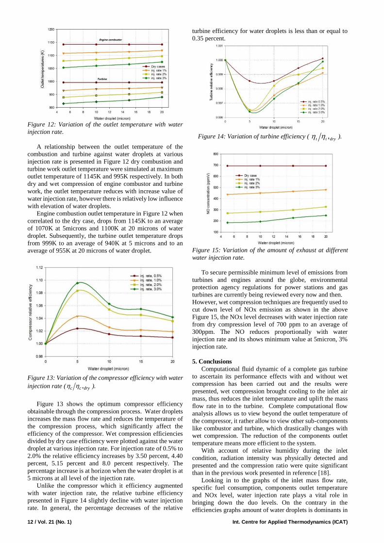
Figure 13: Variation of the compressor efficiency with water
injection rate ( ,c c dry ).
Figure 13 shows the optimum compressor efficiency
obtainable through the compression process. Water droplets
increases the mass flow rate and reduces the temperature of
the compression process, which significantly affect the
efficiency of the compressor. Wet compression efficiencies
divided by dry case efficiency were plotted against the water
droplet at various injection rate. For injection rate of 0.5% to
2.0% the relative efficiency increases by 3.50 percent, 4.40
percent, 5.15 percent and 8.0 percent respectively. The
percentage increase is at horizon when the water droplet is at
5 microns at all level of the injection rate.
Unlike the compressor which it efficiency augmented
with water injection rate, the relative turbine efficiency
presented in Figure 14 slightly decline with water injection
rate. In general, the percentage decreases of the relative
turbine efficiency for water droplets is less than or equal to
0.35 percent.
Figure 14: Variation of turbine efficiency ( ,t t dry ).
Figure 15: Variation of the amount of exhaust at different
water injection rate.
To secure permissible minimum level of emissions from
turbines and engines around the globe, environmental
protection agency regulations for power stations and gas
turbines are currently being reviewed every now and then.
However, wet compression techniques are frequently used to
cut down level of NOx emission as shown in the above
Figure 15, the NOx level decreases with water injection rate
from dry compression level of 700 ppm to an average of
300ppm. The NO reduces proportionally with water
injection rate and its shows minimum value at 5micron, 3%
injection rate.
5. Conclusions
Computational fluid dynamic of a complete gas turbine
to ascertain its performance effects with and without wet
compression has been carried out and the results were
presented, wet compression brought cooling to the inlet air
mass, thus reduces the inlet temperature and uplift the mass
flow rate in to the turbine. Complete computational flow
analysis allows us to view beyond the outlet temperature of
the compressor, it rather allow to view other sub-components
like combustor and turbine, which drastically changes with
wet compression. The reduction of the components outlet
temperature means more efficient to the system.
With account of relative humidity during the inlet
condition, radiation intensity was physically detected and
presented and the compression ratio were quite significant
than in the previous work presented in reference [18].
Looking in to the graphs of the inlet mass flow rate,
specific fuel consumption, components outlet temperature
and NOx level, water injection rate plays a vital role in
bringing down the duo levels. On the contrary in the
efficiencies graphs amount of water droplets is dominants in

Int. J. of Thermodynamics (IJoT) Vol. 21 (No. 1) / 13
state changes. However, with wet compression the engine
operates economically with less specific fuel consumption,
and the pressure ratio is raised while temperature reduction,
which means heat rejection and radiation intensity is utilized
as shown on Figure 2 and Figure 9 respectively. One
important aspect of this research is that, it’s environmentally
friendly, and it cuts the level of NOx toward attaining
allowable environmental protection agency [EPA]
permissible pollution and exhaust level.
Conclusively, one of the setback observed during the
numerical analysis is the slight decline in the turbine relative
efficiency operates with small amount of water droplets even
though it does well in raising the relative efficiency of the
compressor.
Acknowledgements
The authors would like to acknowledged and appreciate
the efforts of turbomachinery research group, Chinese
government scholarship council and tertiary education trust
fund (Tetfund) Nigeria, grant number
HUKP/PS/S/01920/1/82.
Nomenclature
Symbols
𝐴𝑜𝑢𝑡 Area of turbine outlet m2
𝐹𝑁 Engine thrust N
𝐶𝑖𝑛 Speed of the gas at inlet m/s
𝐶𝑜𝑢𝑡 Speed of the gas at outlet m/s
𝐾𝑊 Trap ratio of water
𝑚𝑎 Mass flowrate of air Kg/s
𝑚𝑓 Mass flowrate of fuel Kg/s
𝑚𝑔 Mass flowrate of gas Kg/s
𝑚�� Mass flowrate of water Kg/s
𝑚𝑔 𝐶𝑜𝑢𝑡 Momentum outlet Ns
𝑚𝑔 𝐶𝑖𝑛 Momentum inlet Ns
𝑃𝑖𝑛 Compressor inlet Pressure Pa
𝑃𝑜𝑢𝑡 Turbine outlet pressure Pa
References
[1] Z. Wang, T. Wang, T. Sun, and J. Han, "The Study on the
Performance of the Gas Turbine Exhaust Gas Injection,"
in Power and Energy Engineering Conference
(APPEEC), 2011 Asia-Pacific,Wuhan China, 2011, pp.
1-4. https://www.ieee-pes.org/appeec-2009
[2] E. P. Agency, "Standards of Performance for Stationary
Gas Turbines, Proposed results," vol. / Vol. 77, No. 168
August 29, 2012
https://www.federalregister.gov/documents/2012/08/29
/2012-20524/standards-of-performance-for-stationary-
gas-turbines-standards-of-performance-for-stationary
[3] L. B. Davis and S. Black, "Dry Low NO~ x Combustion
Systems for GE Heavy-Duty Gas Turbines," in
POWERGEN-CONFERENCE-, California USA DEC
5-7, 1995, pp. 57-68.
[4] F. Bonzani and R. Maali, "Low BTU Fuels Operation in
Heavy Duty Gas Turbines: Ansaldo Energia Experience," in ASME 2006 Power Conference,
Atlanta ,Georgia May 2-4 2006, pp. 429-436.
[5] Z. Xun, W. Wu, and D. Han, "A new design and
simulation of gas turbine exhaust ejector," in Fluid
Machinery and Fluid Engineering, 2014 ISFMFE-6th
International Symposium , Wuhan China Oct 22-25,
2014, pp. 1-4.
[6] R. E. Jones, "Gas Turbine Engine Emissions—
Problems, Progress and Future," Progress in Energy and
Combustion Science,elsevier, vol. 4, pp. 73-113, 1978.
[7] A. Mohan, P. K. Chidambaram, A. Suryan, and H. D.
Kim, "Thermo-fluid dynamic analysis of wet
compression process," Journal of Mechanical Science
and Technology, vol. 30, pp. 5473-5483, 2016.
[8] D. Klein and C. Abeykoon, "Modelling of a turbojet gas
turbine engine," in Internet Technologies and
Applications (ITA), 2015, pp. 200-206.
doi: 10.1109/ITechA.2015.7317395
[9] A. Cortinovis, M. Zovadelli, M. Mercangoz, D.
Pareschi, A. De Marco, and S. Bittanti, "Online
adaptation of performance maps for centrifugal gas
compressors," in Control Conference (ECC),
strasbourg,france, july 24,2014, pp. 1036-1041.
[10] X. Liang, Y. Xue, and Z. Li, "Techno-economic analysis
of applying China's R0110 gas turbine in IGCC plants,"
in Materials for Renewable Energy & Environment
(ICMREE), 2011 International Conference shanghai
China, 2011, pp. 1674-1677.
ieeexplore.ieee.org/xpl/mostRecentIssue.jsp?punumber
=5784219...IS...6
[11] F. Zhong, C. Zhou, H. Ma, and Q. Zhang, "Heat Transfer
of Winglet Tips in a Transonic Turbine Cascade,"
Journal of Engineering for Gas Turbines and Power,
vol. 139, p. 012605, 2017.
[12] Q. Jaber, J. Jaber, and M. Khawaldah, "Assessment of
power augmentation from gas turbine power plants
using different inlet air cooling systems," JJMIE, vol. 1,
2007.
[13] A. Andreini, T. Bacci, M. Insinna, L. Mazzei, and S.
Salvadori, "Hybrid RANS-LES Modeling of the
Aerothermal Field in an Annular Hot Streak Generator
for the Study of Combustor–Turbine Interaction,"
Journal of Engineering for Gas Turbines and Power,
vol. 139, p. 021508, 2017.
[14] S. W. Lee, S. U. Kim, and K. H. Kim, "Aerodynamic
performance of winglets covering the tip gap inlet in a
turbine cascade," International Journal of Heat and
Fluid Flow, vol. 34, pp. 36-46, 2012.
[15] Q. Zheng, Y. Sun, S. Li, and Y. Wang, "Thermodynamic
analyses of wet compression process in the compressor
of gas turbine," in ASME Turbo Expo 2002: Power for
Land, Sea, and Air, Amsterdam, Netherlands June 3-6
2002, pp. 487-496.
[16] Q. Zheng and M. Li, "Wet Compression System
Stability Analysis: Part II—Simulations and Bifurcation
Analysis," in ASME Turbo Expo 2004: Power for Land,
Sea, and Air, Vienna, Austria,2004, pp. 713-721.
[17] L. Sun, Q. Zheng, Y. Li, and R. Bhargava,
"Understanding effects of wet compression on separated
flow behavior in an axial compressor stage using CFD
analysis," Journal of Turbomachinery, vol. 133, p.
031026, 2011.
[18] L. Sun, Q. Zheng, Y. Li, M. Luo, and R. K. Bhargava,
"Numerical Simulation of a Complete Gas Turbine

14 / Vol. 21 (No. 1) Int. Centre for Applied Thermodynamics (ICAT)
Engine With Wet Compression," Journal of Engineering
for Gas Turbines and Power, vol. 135, p. 012002, 2013.
[19] A. White and A. Meacock, "An evaluation of the effects
of water injection on compressor performance," in
ASME Turbo Expo Atlanta, Georgia, June 16-19, 2003,
collocated with the 2003 International Joint Power
Generation Conference, 2003, pp. 181-189.
[20] T. Wang and J. R. Khan, "Overspray and Interstage Fog
Cooling in Compressor Using Stage-Stacking Scheme:
Part 1—Development of Theory and Algorithm," in
ASME Turbo Expo 2008: Power for Land, Sea, and Air,
Berlin, Germany June 9-13, 2008, pp. 99-109.
[21] T. Wang and J. R. Khan, "Overspray and Interstage Fog
Cooling in Compressor Using Stage-Stacking Scheme:
Part 2—Case Study," in ASME Turbo Expo 2008: Power
for Land, Sea, and Air, Berlin, Germany June 9-13,
2008, pp. 111-121.
[22] R. K. Yadav and D. K. Reshmi Basak, "Review On Heat
Transfer From Fins," in International Conference on
Advanced Material Technologies (ICAMT),
Visakhapatnam, India December 27-28, 2016.
[23] G. Montalvo-Catano and W. F. O’Brien, "Performance
Modeling of a Power Generation Gas Turbine With Wet
Compression," in ASME 2011 Turbo Expo: Turbine
Technical Conference and Exposition, Vancouver,
Canada June 6-10, 2011, pp. 665-674.
[24] S. O. Oyedepo and O. Kilanko, "Thermodynamic
analysis of a gas turbine power plant modelled with an
evaporative cooler," 2012. International Journal of
Thermodynamic (IJOT) Vol.17 (No.1) pp. 14-20 2014
ISSN 1301-9724 / e-ISSN 2146-1511 doi:
10.5541/ijot.480
[25] C. Matz, G. Cataldi, W. Kappis, G. Mundinger, S.
Bischoff, E. Helland, et al., "Prediction of Evaporative
Effects Within the Blading of an Industrial Axial
Compressor," Journal of Turbomachinery, vol. 132, p.
041013, 2010.
[26] W. M. Elwan, M. R. Shaalan, M. M. Nassief, and M. H.
Gobran, "Computed Effect of Varying Tip Clearance
and Axial Gap on Gas Turbine Stage Performance Part
(I):(Steady Flow)," The Egyptian International Journal
of Engineering Sciences & Technology, vol. 20, pp. 68-
74, 2016.
[27] Z. Mustafa, P. Pilidis, J. A. A. Teixeira, and K. A.
Ahmad, "CFD aerodynamic investigation of air-water
trajectories on rotor-stator blade of an axial compressor
for online washing," in ASME Turbo Expo 2006: Power
for Land, Sea, and Air, Bercelona, Spain May 8-11,
2006, pp. 1385-1394.
[28] M. Rahbar and H. Khaledi, "A study on fuel
consumption at Siemens V94. 2 gas turbine considering
different turbine control methods," in Thermal Power
Plants (CTPP), 2011 Proceedings of the 3rd
Conference , Tehraan,Iran ,October 18-19, 2011, pp. 1-
6. ieeexplore.ieee.org/document/6576967
[29] E. Ulrichs and F. Joos, "Experimental investigations of
the influence of waterdroplets in compressor cascades,"
in ASME Turbo Expo 2006: Power for Land, Bercelona,
Spain May 8-11, Sea, and Air, 2006, pp. 221-230.
[30] G. D. m. Roointon pavri, "Gas Turbine emissions and
control " p. 2, March 2001. GER 4211, GE power
systems, Schenectady, New york, USA. https://st-
powergen.gepower.com
[31] T. Nikolaidis, "Water ingestion effects on gas turbine
engine performance," A phD Thesis published by
Cranfield University, october 2008
[32] H.-s. HU, J.-x. ZHAO, J.-p. ZHONG, R.-w. JIANG, and
M.-z. YIN, "A new adjustment method of combustor
outlet temperature field [J]," Journal of Aerospace
Power, vol. 8, p. 004, 2007.
[33] H. Akimoto and H. Narita, "Distribution of SO2, NOx
and CO2 emissions from fuel combustion and industrial
activities in Asia with 1× 1 resolution," Atmospheric
Environment, vol. 28, pp. 213-225, 1994.
[34] M. Christodoulou, K. Moodie, W. Rattigan, and B.
Ewan, "Safe operation of combined cycle gas turbine
and gas engine systems using hydrogen rich fuels," in
Gas Turbine Instrumentation, EVI-GTI and PIWG Joint
Conference Berlin Germany, 27-29 Sept 2016, pp. 1-36.
[35] G. Bisio and F. Devia, "Interstage cooling in
compressors [for gas turbines]," in Energy Conversion
Engineering Conference, Honololu USA 1997. IECEC-
97., Proceedings of the 32nd Intersociety, pp. 1592-1599.
[36] M. Komjáty, L. Főző, and R. Andoga, "Experimental
identification of a small turbojet engine with variable
exhaust nozzle," in Computational Intelligence and
Informatics (CINTI), 2015 16th IEEE International
Symposium, Budapest, Hungary, 19-21 Nov. 2015, pp.
65-69. ieeexplore.ieee.org/document/7382895/