Effects of Upstream Component and Air Injection on Water ...
12
Research Article Effects of Upstream Component and Air Injection on Water Droplet Impingement Characteristics for Downstream Surfaces Xiaobin Shen , 1,2 Yundan Tan, 1 Rendong Yu, 1 Xiaochuan Liu, 1 Guiping Lin, 1 Zhiqiang Xu, 3 and Yuandong Guo 1 1 Laboratory of Fundamental Science on Ergonomics and Environmental Control, School of Aeronautic Science and Engineering, Beihang University, Beijing 100191, China 2 Key Laboratory of Icing and Anti/De-Icing, China Aerodynamics Research and Development Center, Mianyang, Sichuan 621000, China 3 Wuhan Aviation Instrument Corporation, Wuhan 430074, China Correspondence should be addressed to Yuandong Guo; [email protected] Received 9 April 2021; Revised 19 May 2021; Accepted 12 June 2021; Published 24 June 2021 Academic Editor: Giovanni Delibra Copyright © 2021 Xiaobin Shen et al. This is an open access article distributed under the Creative Commons Attribution License, which permits unrestricted use, distribution, and reproduction in any medium, provided the original work is properly cited. Water droplet changes its movement direction and velocity when it bypasses an aircraft component with the surrounding airflow or gets blown by air injection from the inner part. When the deflected droplet impacts on the downstream surface, its impingement characteristics would be different from those without the frontal effects. In this article, a Lagrangian method was developed to include those upstream effects on the droplet collection efficiency. Validation cases were carried out for a cylinder and an MS (1)-0317 airfoil, whereas a multielement airfoil and an engine cone with a hot air film-heating anti-icing system were computed to investigate the effects of the upstream component and air injection on the impingement characteristics of downstream surfaces. It is found that the present collection efficiencies are in good agreement with the experimental data and the simulation results obtained by the Eulerian and traditional Lagrangian methods when not affected by those upstream factors. The droplet deflections and trajectory crossings are observed clearly under the influence of the upstream component, and the Lagrangian results of downstream surfaces differ from those of the Eulerian method. In addition, due to the air injection from the inner engine cone, the peak collection efficiency on the cone surface increases with the decrease of the droplet diameter and the value even exceeds one when the droplet is small. This work is helpful for the understanding of the droplet motion and the accuracy of aircraft icing simulation. 1. Introduction Aircraft icing is a great threat to flight safety and potential cause of aviation accidents and incidents, which has raised a wide concern. Normally, aircraft icing is the phenomenon that the super-cooled droplets in clouds impinge on the air- craft components and freeze on their surfaces [1]. Where and how many droplets impact on the body determine the position and extent of the ice accretion. Those are defined as droplet impingement characteristics and mainly measured by collection efficiency. To make an ice accretion analysis [2] or design an aircraft anti-icing system [3], it is essential to obtain the local collection efficiency first. Factors that affect the super-cooled droplet motion and surface impingement characteristics include the diameter of the droplets, shape of the aircraft components, and flight status like the altitude, velocity, and attitude [4]. Various components with complex surfaces are mounted on aircrafts, and the one ahead can affect the air flow around the ones in the downstream. When water droplets bypass the upstream surface along with the airflow, their trajectories deflect or even cross due to the influence of inertial force [5]. The spa- tial distribution of water droplets and the distance between the adjacent droplets and other characteristics differ from the situation in the free stream, affecting the local collection efficiency on the downstream surface. For example, when the Hindawi International Journal of Aerospace Engineering Volume 2021, Article ID 2698028, 12 pages https://doi.org/10.1155/2021/2698028
Transcript of Effects of Upstream Component and Air Injection on Water ...
Research ArticleEffects of Upstream Component and Air Injection on WaterDroplet Impingement Characteristics for Downstream Surfaces
Xiaobin Shen ,1,2 Yundan Tan,1Rendong Yu,1Xiaochuan Liu,1Guiping Lin,1 Zhiqiang Xu,3
and Yuandong Guo 1
1Laboratory of Fundamental Science on Ergonomics and Environmental Control, School of Aeronautic Science and Engineering,Beihang University, Beijing 100191, China2Key Laboratory of Icing and Anti/De-Icing, China Aerodynamics Research and Development Center, Mianyang,Sichuan 621000, China3Wuhan Aviation Instrument Corporation, Wuhan 430074, China
Correspondence should be addressed to Yuandong Guo; [email protected]
Received 9 April 2021; Revised 19 May 2021; Accepted 12 June 2021; Published 24 June 2021
Academic Editor: Giovanni Delibra
Copyright © 2021 Xiaobin Shen et al. This is an open access article distributed under the Creative Commons Attribution License,which permits unrestricted use, distribution, and reproduction in any medium, provided the original work is properly cited.
Water droplet changes its movement direction and velocity when it bypasses an aircraft component with the surrounding airflow orgets blown by air injection from the inner part. When the deflected droplet impacts on the downstream surface, its impingementcharacteristics would be different from those without the frontal effects. In this article, a Lagrangian method was developed toinclude those upstream effects on the droplet collection efficiency. Validation cases were carried out for a cylinder and an MS(1)-0317 airfoil, whereas a multielement airfoil and an engine cone with a hot air film-heating anti-icing system were computedto investigate the effects of the upstream component and air injection on the impingement characteristics of downstreamsurfaces. It is found that the present collection efficiencies are in good agreement with the experimental data and the simulationresults obtained by the Eulerian and traditional Lagrangian methods when not affected by those upstream factors. The dropletdeflections and trajectory crossings are observed clearly under the influence of the upstream component, and the Lagrangianresults of downstream surfaces differ from those of the Eulerian method. In addition, due to the air injection from the innerengine cone, the peak collection efficiency on the cone surface increases with the decrease of the droplet diameter and the valueeven exceeds one when the droplet is small. This work is helpful for the understanding of the droplet motion and the accuracyof aircraft icing simulation.
1. Introduction
Aircraft icing is a great threat to flight safety and potentialcause of aviation accidents and incidents, which has raiseda wide concern. Normally, aircraft icing is the phenomenonthat the super-cooled droplets in clouds impinge on the air-craft components and freeze on their surfaces [1]. Whereand how many droplets impact on the body determine theposition and extent of the ice accretion. Those are definedas droplet impingement characteristics and mainly measuredby collection efficiency. To make an ice accretion analysis [2]or design an aircraft anti-icing system [3], it is essential toobtain the local collection efficiency first.
Factors that affect the super-cooled droplet motion andsurface impingement characteristics include the diameter ofthe droplets, shape of the aircraft components, and flightstatus like the altitude, velocity, and attitude [4]. Variouscomponents with complex surfaces are mounted on aircrafts,and the one ahead can affect the air flow around the ones inthe downstream. When water droplets bypass the upstreamsurface along with the airflow, their trajectories deflect oreven cross due to the influence of inertial force [5]. The spa-tial distribution of water droplets and the distance betweenthe adjacent droplets and other characteristics differ fromthe situation in the free stream, affecting the local collectionefficiency on the downstream surface. For example, when the
HindawiInternational Journal of Aerospace EngineeringVolume 2021, Article ID 2698028, 12 pageshttps://doi.org/10.1155/2021/2698028
downstream main wing or flap of a multielement wing isobscured by the slat, no or less water droplets will hit the lead-ing edge [6]. The upstream effects of the components in frontand the air injection on the droplet impingement characteris-tics of downstream surfaces would be more evident on aircraftengine components. Firstly, the air flow and droplet trajecto-ries in the S-shaped inlet duct of a jet engine would bedeflected several times, which in turn affects the dropletimpact on the downstream surfaces [7]. Secondly, the enginenose cone, guide vanes, and rotating blades would always beclosely spaced along the engine shaft, so the droplet collectionefficiencies of the downstream surfaces are inevitably influ-enced by the frontal components [8, 9]. Last but not least,when hot air film-heating anti-icing systems are adopted forthe engine cones and blades, the air injection from those sys-tems can change the properties such as the airflow field andthe movement direction of the water droplets, which therebyaffects the downstream impact characteristics [10]. Generally,in numerical simulations of water droplet impingements, theeffects of the upstream components and air injections needto be taken into account, especially for engine components.
There are mainly two methods for the droplet collectionefficiency: Lagrangian method and Eulerian method. TheLagrangian method tracks the movements of water dropletsin the airflow field and obtains the collection efficiency byanalyzing the impingement trajectories onto the aircraft sur-faces [11]. The solution process is relatively intuitive and easyfor two-dimensional (2D) or geometrically simple surfaces,but for three-dimensional (3D) or complex shapes, it is diffi-cult to determine the particle releasing positions and a largenumber of trajectories has to be computed [12]. TheLagrangian method was employed for the droplet collectionefficiency by the NASA Glenn ice accretion code LEWICE[13]. And NASA has compared the LEWICE predictionswith lots of data from droplet impingement experiments fora variety of different clean airfoils, the airfoils with simulatedice shapes, multielement wings, S-duct engine inlet, etcetera[14–16]. Good agreements were obtained for most of thetested cases, verifying the effectiveness of the Lagrangianmethod for various complex surfaces. As shown in the parti-cle trajectory diagrams given in the references [15, 16], waterdroplets that fail to hit the surface were deflected in theirmovement directions after bypassing the airfoil boundary,especially for the simulated ice shapes, and their trajectoriesbecame denser with some crossings. Dong et al. [10] calcu-lated the droplet impingement characteristics for an aero-engine cone with a hot air film-heating anti-icing system bythe Lagrangian method. Due to the combined effect of theupstream bump and the hot air injection from the anti-icing system, the water droplets were deflected beforeimpacting on the main cone surface and a crossover of thetrajectories was clearly seen. Besides, the trajectory shiftsand crossings after droplets’ flow over the upstream surfaceboundary have also been observed in other literatures [5,17]. It is suggested that the phenomena of deflections andcrossings of the droplet trajectories are objective but theireffects on the downstream impingement characteristics havereceived little attention. The water droplet crossings weredescribed in a NASA validation program for a 3D water
droplet trajectory code using an ECS inlet geometry [18].The trajectory crossings were believed to be caused by badleast square coefficients in certain flow field cells and resultedin irregular and incorrect water impingement patterns on thesurface. Through code improvement, trajectory crossings ofsmall-diameter droplets remained, affecting the collectionefficiency distribution. It can be concluded that the upstreameffects influence the droplet motion and may lead to crossingtrajectories, which in turn affects the local droplet collectionefficiency downstream.
The Eulerian method, on the other hand, considers thewater droplet as a continuous phase and, after introducingthe concept of the droplet volume fraction, obtains the distri-butions of the droplet volume fraction and velocity at spatialgrid cells by solving the continuity and momentum equationsof the droplet phase [19]. This method is a field-theoreticidea and an air-droplet two-phase flow approach, whichcan solve for the local collection efficiencies of all 3D surfacesat once. In the simulations of the ice accretion processes andanti-icing systems in the FENSAP-ICE software, the dropletcollection efficiency is obtained by a 3D Eulerian method[20]. This method of FENSAP-ICE has already been utilizedin the droplet calculation for complex components like 3Dwings, rotorcraft, and jet engines [21, 22]. In addition, Wirogoand Srirambhatla [19] presented a Eulerian approach inFLUENT software and validated it for 2D and 3D bodies.Then, the Eulerian method was used for a 3D multielementwing and the collection efficiency was obtained on the slat,main wing, and flap, which showed the shading effect of theupstream surfaces. In the Eulerian method, droplet velocityis a single value function in each cell and the streamlines ofwater droplets never intersect each other. When the trajecto-ries of water droplets cross in practice, an infinite densityimpulse would occur, resulting in local singularity of dropletconcentration and numerical instability in the Eulerianmethod [12]. Stabilization terms [23], such as numerical dif-fusion [12] and artificial viscosity [20], should be added toeliminate the droplet oscillations and ensure convergence.Therefore, although the Eulerian method can partly trackthe occlusion effects of the upstream surfaces on dropletmotion, it cannot capture the trajectory crossings andimpingement characteristics accurately. With the enhancedregion of droplet volume fraction diffused by the stabilizationterms, the Eulerian collection efficiency for downstream sur-faces might differ from the actual situation.
Since the Eulerian method was a relatively new approach,its results were usually compared with those obtained by thetraditional Lagrangian method. It turned out that the twomethods obtained consistent results for common surfacessuch as cylinder and single airfoils [12, 19]. However, whenIuliano et al. [24] performed droplet impingement predictionon a multielement airfoil with the Eulerian and Lagrangianmethods, it was found that the Lagrangian limit trajectoriesof the water droplets deviated far away from the Euleriandroplet streamlines after bypassing a surface boundary. Inaddition, the collection efficiencies of the twomethods agreedvery well on the frontal main multielement component butdiffer a lot on the downstream flap surface. Those resultsreflected the fact that the droplet impingement characteristics
2 International Journal of Aerospace Engineering
of downstream surfaces can be affected by the upstream effectsand the Eulerian and Lagrangian methods tracked thoseeffects in different ways, leading to different results. The twomethods might not be equivalents under those upstreameffects.
In general, water droplets are deflected or crossed by theupstream effects such as component airflow bypassing oranti-icing hot air injection, which determines the dropletimpingement characteristics on the downstream surfaces.Droplet trajectory deflections and crossings can be found inthe literatures with the Lagrangian method, but their influ-ence has received little attention, and the traditional defini-tion of the droplet collection efficiency did not considerthose conditions. In contrast, the Eulerian method is unableto capture the droplet crossings and thus cannot get an accu-rate pattern of the upstream effects. In this paper, we investi-gate the effects of the upstream component and air injectionon the motion and impingement characteristics of the super-cooled water droplets in clouds and establish a numericalsolution to analyze the mechanism of the effects. Firstly, thedroplet deflections and trajectory crossings under the effectsof the upstream objects and air injection in front aredescribed in Section 2, and a Lagrangian method with anew definition of the droplet collection efficiency is devel-oped to consider those effects. Then, a cylinder and an MS(1)-0317 airfoil are used to validate the Lagrangian methodin Sections 3.1 and 3.2, and the Lagrangian and Eulerianmethods obtain almost the same results. After that, the effectof the upstream component on droplet motion is studied fora multielement airfoil, and different results appear in the twomethods and are analyzed in detail. At last, an engine conewith a hot air film-heating anti-icing system is computedfor the combined effects of the upstream component, andair injection and complex distributions of collection effi-ciency are found on the downstream cone surface with themaximum value larger than one. Since LEWICE uses thetraditional Lagrangian method and FENSAP-ICE adoptsonly the Eulerian method for the droplet impingementcharacteristics, this study is useful for the better under-standing of the droplet motion and the improvement ofthe droplet calculation under the effects of upstream com-ponents and air injections.
2. Numerical Simulation Methods
Since the Eulerian approach cannot capture trajectory cross-ings, the Lagrangian method is adopted to simulate themotion of water droplets and study the upstream effects onthe impingement characteristics. In the Lagrangian frame-work, the movement of each particle is calculated individu-ally to get its path line and determine whether it impingeson the aircraft surface or not. By integrating many trajecto-ries, the collection efficiency can be obtained. Efforts havebeen made to reduce the droplet number to improve the effi-ciency of the Lagrangian method [5], for the computationalcosts are very expensive when a very large number of dropletsare tracked for complex surfaces and 3D objects. However,when water droplets are affected by the frontal factors, it isnecessary to compute lots of trajectories to capture their
deflections and crossings. Therefore, the efficient Lagrangianalgorithms with less tracked particles are not introduced inthis work. In addition, the traditional definition of the dropletcollection efficiency does not work when the droplet trajecto-ries intersect each other and cannot express the dropletimpingement characteristics under the upstream effects.Therefore, the traditional one-way coupling Lagrangianmethod is extended with a new definition of the droplet col-lection efficiency to consider the trajectory crossings. Themathematical model of the Lagrangian method is presentedin Section 2.1, and the solution process and simulation stepsare illustrated in Section 2.2.
2.1. Mathematical Model. The following assumptions aremade for the motion of a water droplet in the airflow field[5, 12]: (1) the droplet remains spherical with no deforma-tion, breaking, or splashing, (2) droplets do not have mutualinfluence, and neither collisions nor coalescence occur, and(3) the drag force of the surrounding air is the only one exert-ing on the droplet and all the others including gravity areignored. Then, the movement of the water droplet can bedetermined by Newton’s second law, expressed as [19].
dudt
= K ua − uð Þ, ð1Þ
where u is the droplet velocity vector, t is the time, ua is theair velocity vector, and K is the air-droplet exchange coeffi-cient, given as [5]
K = 18μaρd2
CD Re24 , ð2Þ
where ua is the air viscosity, ρ is the droplet density, d is thedroplet diameter, and CD is the drag coefficient. Re is the rel-ative Reynolds number and is calculated by
Re = ρa ∣ ua − u ∣ dμa
, ð3Þ
where ρa is the air density.The path line of a water droplet can be obtained by inte-
grating the equation of the particle motion (equation (1))through the surrounding airflow field. With all the trajecto-ries of the droplets ending on the object surface, the collec-tion efficiency β can be obtained, which is defined inLEWICE as the efficiency with which any location on theobject surface will collect water droplets [13]. In the Lagrang-ian framework, the local collection efficiency at each point onthe object is usually calculated by [5, 13]
β = dyds
, ð4Þ
where ds is the surface wrap distance between the trajectoriesof neighbouring droplets on the object and dy is the distanceof the initial positions of the corresponding particles. Since dsis usually larger than dy due to the inertia of the droplet,
3International Journal of Aerospace Engineering

collection efficiency is always below one [8, 25], as the casebetween droplet no. 1 and droplet no. 2 in Figure 1.
However, when droplet motion is deflected by upstreameffects, it is possible that dy becomes larger than ds, resultingin a collection efficiency bigger than one. Figure 1 presents asketch map of an engine cone with a hot air anti-icing system,which is similar to that described in the reference [10]. Whendroplets bypass the upstream bump of the cone, their trajec-tories change directions and then end on the downstreammain cone surface, as shown in Figure 1. In addition, dueto the air injection from the anti-icing system in front ofthe main cone, droplets would move away from the jet siteand the closer to the hot air outlet, the greater the changeof the movement direction. As a result of those combinedeffects, ds between droplet no. 4 and droplet no. 5 is smallerthan dy and the collection efficiency bigger than one isobtained there. Moreover, trajectory crossings would happenbefore droplet impinging on the object. Therefore, two drop-lets could impact on the same location (see droplet no. 3 andno. 5 in Figure 1), causing an infinite value of β. Furthermore,the value of ds between the 3rd and 4th droplets is even nega-tive. It can be seen that the local collection efficiency underthe upstream effects could not be obtained by equation (4)anymore.
In this work, the Lagrangian method is extended to adaptto these conditions in consideration of upstream effects. Themass flux-based collection efficiency mentioned in reference[8] is introduced, which is the ratio of the local droplet massflux at the object surface to its value at the far field inlet.When the initial distances between the adjacent releasingpoints are the same and all equal to dy, the water dropletcan be considered as a microelement with a width of dyinstead of just a massless point (see droplet no. 5 inFigure 1), and then, the mass flux of a droplet in 2D condi-tions would be
m = LWC · u∞ · dy, ð5Þ
where LWC is the liquid water content (grams of water con-tained in a cubic meter of air) and u∞ is the freestream veloc-ity. When a droplet trajectory ends in a control volume (CV)on the surface, the mass flux of the droplet is absorbed by theCV. Hence, the total mass flux of the impingement dropletsin the ith CV can be calculated according to the total numberN of the droplet trajectories ending in the CV and its localdroplet collection efficiency on the surface can be obtained by
βi =LWC · u∞ · dy ·NLWC · u∞ · Δsi
= N · dyΔsi
, ð6Þ
where Δsi is the curve length of the ith CV. According toequation (6), the trajectory crossings and the condition ofthe same impingement location can be considered in theextended Lagrangian method. The mass flux-based collectionefficiency, which is similar to the definition in the Eulerianmethod, is the average of the traditional results in a controlvolume.
2.2. Solution Procedure. The droplet impingement simulationbased on the extended Lagrangian method is carried out inthe commercial CFD software Ansys FLUENT-19.1 with itsuser-defined functions (UDFs) [26]. Firstly, the steady air-flow field is obtained by solving the Reynolds averagedNavier-Stokes equations (RANS) with the finite volumesolver of FLUENT. Droplet motion is insensitive to the air-flow in the boundary layer, and even the inviscid flow fieldswork well for the droplet impingement characteristics [12].In this work, the one-equation Spalart-Allmaras turbulencemodel is used to catch the upstream effects on the air flow.However, the dispersion of droplets due to turbulence isnot considered. The SIMPLE (semi-implicit method forpressure-linked equations) algorithm is employed with thediscretization of the second-order upwind scheme for theCFD calculation. Since the LWC and droplet diameter inthe cloud is small, the aerodynamic effects of droplets onthe airflow field are negligible [27]. Then, the droplet motionis decoupled from the airflow calculation (one-way coupling)and solved in a freezing airflow field with a fourth-orderRunge-Kutta scheme. The solution of a droplet path linestarts at a released location far away from the object surfacewhere the air velocity is the same with the freestream valueand ends with a trap boundary condition when it intersectsthe object surface or reaches the downstream far fieldboundary. The tracked particles are more than 105 to guar-antee the independence of the number of the droplets injectedin the Lagrangian method. At last, UDFs are used to integratethe trajectories ending in each CV on the object surfaces andevaluate the local collection efficiency by equation (6).
3. Results and Discussions
To verify the present Lagrangian method, the known dropletvalidation cases of a cylinder and an MS (1)-0317 airfoil areused by comparing the collection efficiency and impinge-ment limits to the experimental data and the simulationresults from the literatures. Then, a multielement airfoil
Hot air inlet
654321 dy ds
Free stream
Droplet
dy
Bump
Main conesurface
Injection
Figure 1: Droplet trajectories and collection efficiency underupstream effects.
4 International Journal of Aerospace Engineering

and a section of an engine cone are selected to study theupstream effects of the frontal object and air injection.
3.1. Cylinder. The first validation case is a circular cylinderwith a diameter of 10.16 cm in reference [12]. The freestreamvelocity is 80m/s, and the density of air is set to be 1.097kg/m3 with an ambient pressure of 89867Pa. Seven differentdroplet sizes with a median volumetric diameter (MVD) of16μm, which satisfy the Langmuir-D distribution, are com-puted separately for the droplet impingement characteristics,as listed in Table 1. The composite collection efficiency in adistribution of a droplet size can be obtained by [12]
β = 〠M
j=0wjβj, ð7Þ
where M is the total number of the droplet sizes, wj is thepercentage of the jth droplet group, and βj is the correspond-ing collection efficiency.
Figure 2 shows the contour of air velocity around the cyl-inder, along with the droplet trajectories obtained by theLagrangian method. In front, far away from the cylinder,water droplets keep their motion at the free air velocity.When they are close to the cylinder, their movement direc-tions change because of the air flow around the surface andthe trajectories deviate from the air streamlines due to the
inertia. Parts of droplets impinge on the leading edge of thecylinder, and the droplet impingement limits are located atthe points where the trajectories are tangent to the cylindersurface. For the droplets failing to impact on the cylinder,the one relatively closer to the cylinder is affected moresharply by the airflow change, leading to a stronger deflec-tion, while the airflow’s influence is rather limited on thedroplets away from the surface. Due to this reason, a concen-trated zone of the droplet trajectories is formed near the rearof the cylinder. Even more, trajectory overlaps and crossingsare found in some certain areas.
The collection efficiencies of the seven droplet sizes in theLangmuir-D distribution are presented in Figure 3. The localcollection efficiency distributes symmetrically on the cylindersurface, summits at the stagnation point, and decreasesalongside both the pressure and suction surfaces until itbecomes zero at the impingement limits. It can be seen thatthe droplet diameter has a strong connection with theimpingement characteristics. When the droplet size is larger,which means bigger inertia and larger deviation from the airstreamlines, it would result in a wider impingement regionand larger peak collection efficiency.
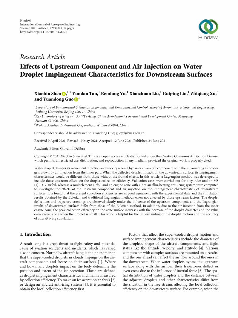
Comparison of collection efficiency between the compos-ite value with Langmuir-D distribution and the experimentaldata is presented in Figure 4, where the shaded region is therange of the experimental data. It can be seen that the peaklocal collection efficiency obtained in this work is a littlesmaller than that obtained by the Eulerian method [12] butthe similar impingement regions are attained in bothmethods. In addition, the simulation result matches well withthe experimental data, which validates the present Lagrang-ian method.
3.2. MS (1)-0317 Airfoil. An MS (1)-0317 airfoil with a chordlength of 0.9144m is taken from the Papadakis’ dropletimpingement experiments [16] as the second validation case
x (m)
y (m
)
–0.06 –0.04 –0.02 0 0.02 0.040
0.02
0.04
0.06
0.08
0.1
Velocity (m/s)
10 20 30 40 50 60 70 80 90 100 110 120 130
Figure 2: Lagrangian droplet trajectories on contour of air velocityaround the cylinder at the droplet diameter of 16 μm.
–80 –60 –40 –20 0 20 40 60 80
0.4
0.2
0.0
0.6
0.8
1.0
s (mm)
d = 5 µmd = 8.3 µmd = 11.4 µm
d = 16 µm
d = 21.9 µmd = 27.8 µmd = 35.5 µm
𝛽
Figure 3: Collection efficiency of the cylinder for various dropletsizes at the MVD of 16μm in Langmuir-D distribution.
Table 1: The Langmuir-D distribution for MVD = 16μm.
No. wj (%) d (μm)
1 5 5.0
2 10 8.3
3 20 11.4
4 30 16.0
5 20 21.9
6 10 27.8
7 5 35.5
5International Journal of Aerospace Engineering
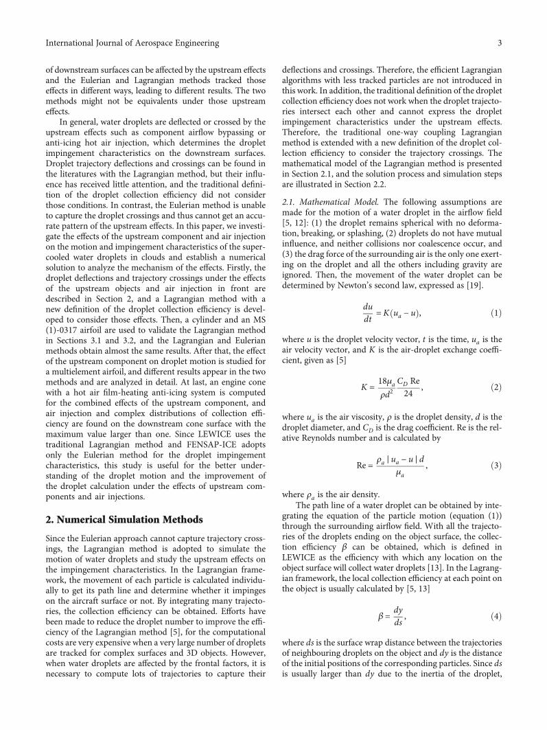
for the present Lagrangian method. The test condition is atthe freestream velocity of 78.23m/s with the MVD of 21μm. The droplet size distribution was measured in the exper-
iment, and a 10-bin discrete droplet size distribution wasgenerated as an approximation for the droplet impingementcharacteristics. The 10-bin droplet size distribution of theMVD is listed in Table 2, and the composite collection effi-ciency is also computed by equation (7). The test was carriedout at an angle of attack (AOA) of 0° in the Goodrich IcingWind Tunnel. However, the AOA used in the LEWICE anal-ysis and in this work is set to be −1.85° to match the experi-mental pressure distribution on the airfoil surface, since theairflow field around the MS (1)-0317 airfoil was affected bythe narrow tunnel walls [16]. In addition, the inlet pressureis 95292 Pa and the air density is 1.213 kg/m3.
The Lagrangian droplet trajectories and the air velocitydistribution around the MS (1)-0317 airfoil are shown in
ExperimentLEWICEPresent
–0.15 –0.10 –0.05 0.00 0.05 0.10 0.15
0.4
0.2
0.0
0.6
0.8
1.0
s (m)
𝛽
Figure 7: Comparison of collection efficiency with experimentaland LEWICE results for the MS (1)-0317 airfoil.
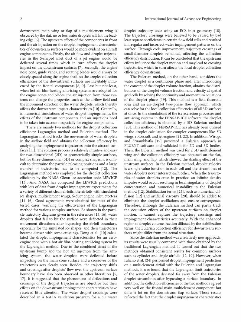
Table 2: The 10-bin droplet size distribution for MVD= 21 μm.
Bin no. wi (%) d (μm)
1 5 4.040659
2 10 9.67207
3 20 14.24772
4 30 20.9438
5 20 28.15316
6 10 45.23621
7 3 70.07175
8 1 88.85927
9 0.5 103.4068
10 0.5 163.9674
x (m)
y (m
)
0
10 20 30 40 50 60 70 80 90
0.05 0.1 0.15
–0.05
0
0.05
0.1
Velocity (m/s)
Figure 5: Lagrangian droplet trajectories on contour of air velocityaround the MS (1)-0317 airfoil at the droplet diameter of 20.9 μm.
–0.3 –0.2 –0.1 0 0.1 0.2
s (m)
d = 4.04 µmd = 9.67 µmd = 14.24 µm
d = 20.94 µmd = 28.15 µm
d = 45.23 µmd = 70.07 µmd = 88.85 µm
d = 103.40 µmd = 163.96 µm
0.4
0.2
0.0
0.6
0.8
1.0
𝛽
Figure 6: Collection efficiency of the MS (1)-0317 airfoil for variousdroplet sizes at the MVD of 21μm in the 10-bin distribution.
–80 –60 –40 –20 0 20 40 60 80
0.4
0.3
0.2
0.1
0.0
0.6
0.5
0.7
s (mm)
𝛽
Figure 4: Comparison of collection efficiency with experimentaland Eulerian results for the cylinder.
6 International Journal of Aerospace Engineering
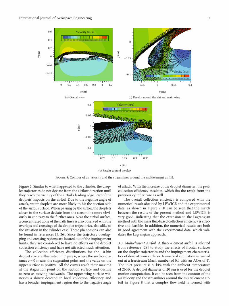
Figure 5. Similar to what happened to the cylinder, the drop-let trajectories do not deviate from the airflow direction untilthey reach the vicinity of the airfoil’s leading edge. Part of thedroplets impacts on the airfoil. Due to the negative angle ofattack, water droplets are more likely to hit the suction sideof the airfoil surface. When passing by the airfoil, the dropletscloser to the surface deviate from the streamline more obvi-ously in contrary to the further ones. Near the airfoil surface,a concentrated zone of the path lines is also observed with theoverlaps and crossings of the droplet trajectories, also alike tothe situation in the cylinder case. These phenomena can alsobe found in references [5, 26]. Since the trajectory overlap-ping and crossing regions are located out of the impingementlimits, they are considered to have no effects on the dropletcollection efficiency and have not attracted much attention.
The collection efficiency distributions for the 10-bindroplet size are illustrated in Figure 6, where the surface dis-tance s = 0 means the stagnation point and the value on theupper surface is positive. All the curves reach their maximaat the stagnation point on the suction surface and declineto zero as moving backwards. The upper wing surface wit-nesses a slower descend in local collection efficiency andhas a broader impingement region due to the negative angle
of attack. With the increase of the droplet diameter, the peakcollection efficiency escalates, which fits the result from theprevious cylinder case as well.
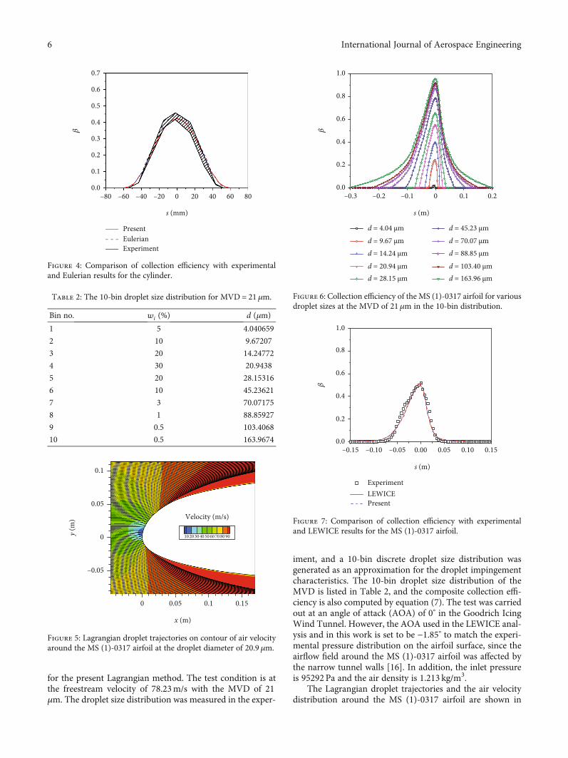
The overall collection efficiency is compared with thenumerical result obtained by LEWICE and the experimentaldata, as shown in Figure 7. It can be seen that the matchbetween the results of the present method and LEWICE isvery good, indicating that the extension to the Lagrangianmethod with the mass flux-based collection efficiency is effec-tive and feasible. In addition, the numerical results are bothin good agreement with the experimental data, which vali-dates the Lagrangian approach.
3.3. Multielement Airfoil. A three-element airfoil is selectedfrom reference [28] to study the effects of frontal surfaceson the droplet trajectories and the impingement characteris-tics of downstream surfaces. Numerical simulation is carriedout at a freestream Mach number of 0.4 with an AOA of 4°.The inlet pressure is 80 kPa with the ambient temperatureof 260K. A droplet diameter of 20μm is used for the dropletmotion computation. It can be seen from the contour of theair velocity and the streamlines around the multielement air-foil in Figure 8 that a complex flow field is formed with
Velocity (m/s)
x (m)
y (m
)
0
20 40 60 80 100 120 140 160 180 200 220 240 280260
0.2 0.4 0.6 0.8 1.21
–0.02
–0.04
0.2
0
0.4
0.6
(a) Overall view
x (m)
y (m
)
–0.05 0 0.05 0.1
–0.05
–0.1
0
Velocity (m/s)
20 40 60 80 100 120 140 160 180 200 220 240 280260
(b) Results around the slat and main wing
x (m)
y (m
)
0.75 0.8 0.85 0.9 0.95
–0.05
–0.1
0
0.05
0.1 Velocity (m/s)
20 40 60 80 100 120 140 160 180 200 220 240 280260
(c) Results around the flap
Figure 8: Contour of air velocity and the streamlines around the multielement airfoil.
7International Journal of Aerospace Engineering

vortexes, since the tailing edges of the slat and main wing donot transient smoothly with air streamlines and have largewindward areas. The wake of the forward bodies interactswith the airflow around the multielement airfoil, which dis-torts the droplet trajectories and affects the local collectionefficiency on the downstream surfaces. Especially in the areabetween the slat and the main wing, the slat is located lowerthan the main wing and they are so close to each other. At apositive angle of attack, the air has to bypass the lower slatsurface, flows through the space between the slat and themain wing, and then reaches the leading edge of the mainwing. The airflow is divided into two streams, which flowthrough the pressure and suction surfaces of the main wing,as shown in Figure 8. It makes the stagnation point appearat a lower location and creates an even more complex airflowin front of the main wing.
From the trajectories demonstrated in Figure 9, waterdroplets impinge on the slat and the pressure surface of themain wing and the front part of the flap. In the rear area ofthe slat, the trajectories missing the upstream elements forma concentrated zone, which means that the distance betweenthe adjacent trajectories is smaller than where they start.When droplets bypass the pressure surface of the slat, they
continue their trajectories to the region with a complex vor-tex flow between the slat and the main wing, and change theirmovement directions again. Some of the droplets finallyimpinge on the pressure surface of the main wing with anirregular distribution of the impact points. Due to droplets’inertia, none of them moves to the upper wing surface withthe airflow. In the same way like the slat, a concentrated zoneof the droplet trajectories is formed below the main wing.However, since the main wing has a much larger area andlonger chord with a smoother profile, the distance betweenneighbouring trajectories do not have apparent changesbefore droplets arrive on the flap. In addition, the flap islocated behind and below the main wing, and distant fromit, so the airflow around the flap is slightly affected by themain wing or the frontal slat, leading to a smoother distribu-tion of the impingement positions.
The collection efficiencies of the slat, main wing, and flapare compared with those obtained by the Eulerian method[28], as shown in Figure 10. It is found that the presentmethod could successfully capture the droplet impingementregions and characteristics for the multielement airfoil. Sincethere is no effect of the upstream surface on the slat, thelocal collection efficiency there coincides very well with that
x (m)
y (m
)
0 0.2 0.4 0.6 0.8 1.21
–0.2
–0.4
0.2
0
0.4
0.6
(a) Overall view
x (m)
y (m
)
0–0.05 0.05 0.1
–0.05
–0.1
0
(b) Results around the slat and main wing
x (m)
y (m
)
0.75 0.8 0.85 0.9 0.95
–0.05
–0.1
0
0.05
0.1
(c) Results around the flap
Figure 9: Lagrangian droplet trajectories around the multi-element airfoil at the droplet diameter of 20 μm.
8 International Journal of Aerospace Engineering

of the Eulerian method, which also validates the developedLagrangian method. A great difference is found on themain wing surface. The present collection efficiency has alarger value, but a smaller range than the Eulerian resultin the upper region. The phenomena of the same collectionefficiency on the frontal surface and different results on thedownstream component were also observed in the simula-tions with the two methods in reference [24]. This mightbe attributed to the different ways of dealing with dropletmotion after being deflected by the upstream flow. In theLagrangian method, droplets’ trajectories are tracked oneby one in the airflow and this approach works very welleven when the droplet motion is strongly affected by thecomplex wake flow as shown in Figure 9. On the otherhand, droplet velocity is a single value function in theEulerian method [12]. When the droplet motion isdeflected, two droplet streams might gather to a singledirection, causing an infinite droplet volume fraction andlocal singularity of droplet concentration. Numerical diffu-sion is added in the continuity equation of the dropletphase to smooth out the local singularity in the Eulerianmethod [28]. When the droplet concentration due to thewake flow is diffused in front of the main wing, a smootherdistribution of the collection efficiency is obtained on thewing surface.
For the same reason, the divergence in the local collectionefficiency on the flap can be understandable. After the waterdroplets flow by the main wing, the concentrated zone isformed. The droplet concentration in this region is diffusedin the Eulerian method, while the Lagrangian method cap-tures it very well under the condition that massive dropletsare tracked. Since the main wing has a larger area, the airstreamlines transit slowly below the pressure surface andresult in a relatively sparse distribution of the droplets.Besides, the long distance and relative position between theflap and the wing further limit the influence of the upstreamon the flap. Therefore, these two methods obtain differentcollection efficiencies only at the frontal area of the flap andthe Lagrangian result is more irregular.
3.4. Section of an Engine Cone. As described in Section 1, thehot air film-heating anti-icing system can be used in aero-engine cones [10]. A section of this engine cone is investi-gated for the effects of the upstream surface and air injectionon the droplet trajectories and the impingement characteris-tics of the downstream surface. Since the airflow and localcollection efficiency in the axisymmetric coordinate needspecial treatment [10], a simple 2D section model of theengine cone is tested, as shown in Figure 11. In addition,the temperature difference between the free stream and theanti-icing hot air is ignored to focus on the effects of theinjection air flow. The freestream velocity is 40m/s, andthe ambient pressure is 1 atm with a temperature of 300K.The mass flow rate of the hot air is 0.0575 kg/s. The dropletdiameters of 18μm, 20μm, and 24μm are used in thesimulation.
The air velocity field around the engine cone is shown inFigure 11, along with the Lagrangian droplet trajectories at adiameter of 20μm. The freestream air flows to the frontalbump of the engine cone and then moves downstream. Withthe hot air jet from the outlet of the anti-icing system, themixed air flows backward along the main cone surface.Meanwhile, the motion of the water droplet is affected bothby the cone surfaces and the hot air injection, and the drop-lets impinge on both the bump and the downstream conesurfaces. Since the effects of the bump surface and the airinjection are mainly on the downstream droplet motion,attention is fixed on the droplet impingement characteristicsof the main cone surface.
The droplet trajectories near the hot air jet site aroundthe engine cone are shown in detail in Figure 12. It can beseen that water droplets change their movement directionsin front of the main cone mainly due to the hot air injection.When the droplets are at a diameter of 24μm, the deflectionof water droplets from their original movement trend is rela-tively small due to the large inertia, as shown in Figure 12(a).The distance between neighbouring trajectories becomessmaller before impact on the main cone, but no droplet cross-ings are observed with the sparse path lines. When the drop-lets’ diameter is 20μm, more obvious deflection is found in
Velocity (m/s)
Hot air inlet
x (m)
y (m
)
0 0.02–0.04 –0.02 0.04 0.06 0.08 0.1
–0.02
–0.04
–0.06
0.02
00 10 15 20 25 30 35 40 45 50 55
0.04
0.06
Figure 11: Lagrangian droplet trajectories on the contour of airvelocity around the cone section at the droplet diameter of 20μm.
EulerianPresent slat
Present flapPresent wing
–0.12 –0.10 –0.08 –0.06 –0.04 –0.02 0.00
0.4
0.2
0.0
0.6
0.8
1.0
y (m)
𝛽
Figure 10: Comparison of collection efficiency with the Eulerianresult for the multielement airfoil at the droplet diameter of 20 μm.
9International Journal of Aerospace Engineering
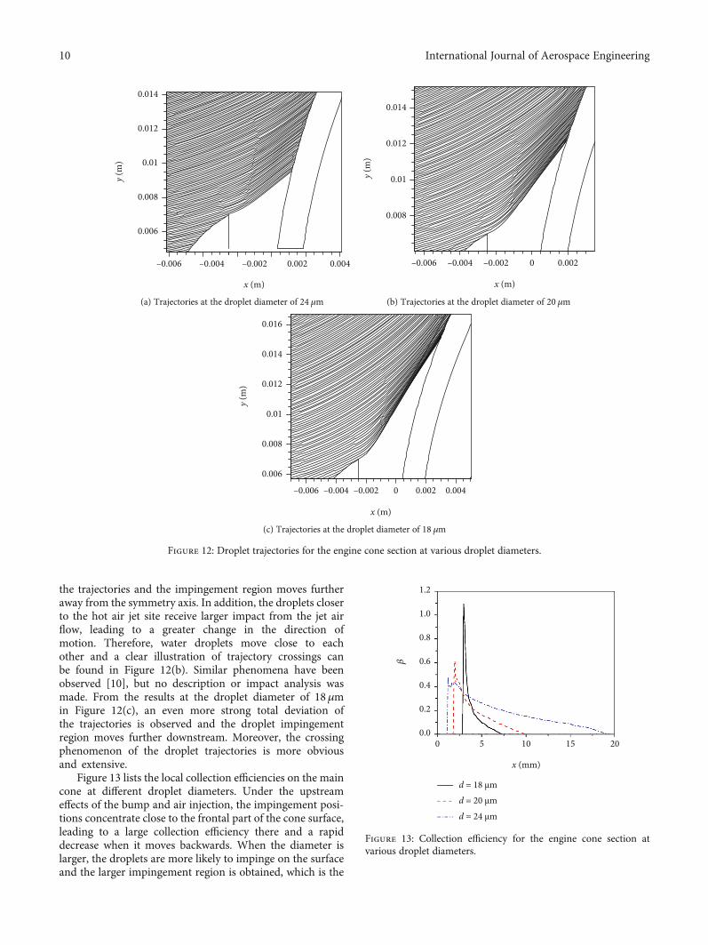
the trajectories and the impingement region moves furtheraway from the symmetry axis. In addition, the droplets closerto the hot air jet site receive larger impact from the jet airflow, leading to a greater change in the direction ofmotion. Therefore, water droplets move close to eachother and a clear illustration of trajectory crossings canbe found in Figure 12(b). Similar phenomena have beenobserved [10], but no description or impact analysis wasmade. From the results at the droplet diameter of 18μmin Figure 12(c), an even more strong total deviation ofthe trajectories is observed and the droplet impingementregion moves further downstream. Moreover, the crossingphenomenon of the droplet trajectories is more obviousand extensive.
Figure 13 lists the local collection efficiencies on the maincone at different droplet diameters. Under the upstreameffects of the bump and air injection, the impingement posi-tions concentrate close to the frontal part of the cone surface,leading to a large collection efficiency there and a rapiddecrease when it moves backwards. When the diameter islarger, the droplets are more likely to impinge on the surfaceand the larger impingement region is obtained, which is the
x (m)
y (m
)
–0.006 –0.004 –0.002 0.002 0.004
0.008
0.006
0.01
0.012
0.014
(a) Trajectories at the droplet diameter of 24 μm
x (m)
y (m
)
–0.002–0.006 –0.004 0 0.002
0.008
0.01
0.012
0.014
(b) Trajectories at the droplet diameter of 20 μm
x (m)
y (m
)
–0.006 –0.004 –0.002 0 0.002 0.004
0.008
0.006
0.01
0.012
0.014
0.016
(c) Trajectories at the droplet diameter of 18 μm
Figure 12: Droplet trajectories for the engine cone section at various droplet diameters.
0 5 10 15 20
0.4
0.2
0.0
0.6
0.8
1.0
1.2
x (mm)
d = 18 µmd = 20 µmd = 24 µm
𝛽
Figure 13: Collection efficiency for the engine cone section atvarious droplet diameters.
10 International Journal of Aerospace Engineering
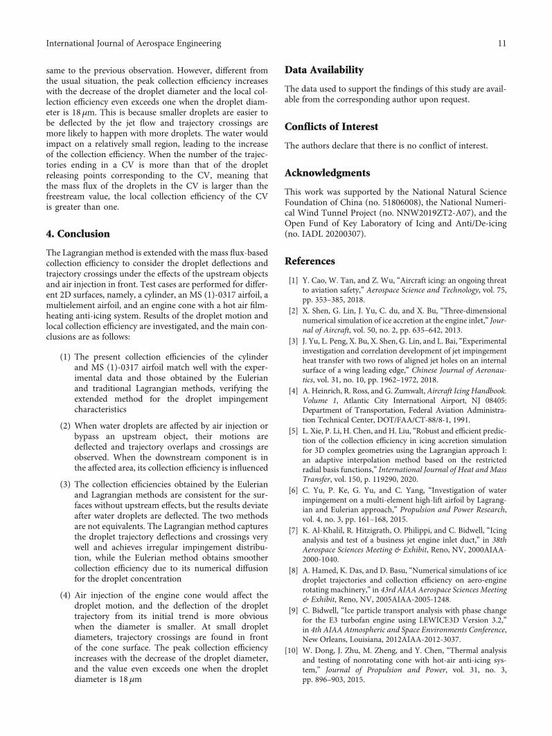
same to the previous observation. However, different fromthe usual situation, the peak collection efficiency increaseswith the decrease of the droplet diameter and the local col-lection efficiency even exceeds one when the droplet diam-eter is 18μm. This is because smaller droplets are easier tobe deflected by the jet flow and trajectory crossings aremore likely to happen with more droplets. The water wouldimpact on a relatively small region, leading to the increaseof the collection efficiency. When the number of the trajec-tories ending in a CV is more than that of the dropletreleasing points corresponding to the CV, meaning thatthe mass flux of the droplets in the CV is larger than thefreestream value, the local collection efficiency of the CVis greater than one.
4. Conclusion
The Lagrangian method is extended with the mass flux-basedcollection efficiency to consider the droplet deflections andtrajectory crossings under the effects of the upstream objectsand air injection in front. Test cases are performed for differ-ent 2D surfaces, namely, a cylinder, an MS (1)-0317 airfoil, amultielement airfoil, and an engine cone with a hot air film-heating anti-icing system. Results of the droplet motion andlocal collection efficiency are investigated, and the main con-clusions are as follows:
(1) The present collection efficiencies of the cylinderand MS (1)-0317 airfoil match well with the exper-imental data and those obtained by the Eulerianand traditional Lagrangian methods, verifying theextended method for the droplet impingementcharacteristics
(2) When water droplets are affected by air injection orbypass an upstream object, their motions aredeflected and trajectory overlaps and crossings areobserved. When the downstream component is inthe affected area, its collection efficiency is influenced
(3) The collection efficiencies obtained by the Eulerianand Lagrangian methods are consistent for the sur-faces without upstream effects, but the results deviateafter water droplets are deflected. The two methodsare not equivalents. The Lagrangian method capturesthe droplet trajectory deflections and crossings verywell and achieves irregular impingement distribu-tion, while the Eulerian method obtains smoothercollection efficiency due to its numerical diffusionfor the droplet concentration
(4) Air injection of the engine cone would affect thedroplet motion, and the deflection of the droplettrajectory from its initial trend is more obviouswhen the diameter is smaller. At small dropletdiameters, trajectory crossings are found in frontof the cone surface. The peak collection efficiencyincreases with the decrease of the droplet diameter,and the value even exceeds one when the dropletdiameter is 18μm
Data Availability
The data used to support the findings of this study are avail-able from the corresponding author upon request.
Conflicts of Interest
The authors declare that there is no conflict of interest.
Acknowledgments
This work was supported by the National Natural ScienceFoundation of China (no. 51806008), the National Numeri-cal Wind Tunnel Project (no. NNW2019ZT2-A07), and theOpen Fund of Key Laboratory of Icing and Anti/De-icing(no. IADL 20200307).
References
[1] Y. Cao, W. Tan, and Z. Wu, “Aircraft icing: an ongoing threatto aviation safety,” Aerospace Science and Technology, vol. 75,pp. 353–385, 2018.
[2] X. Shen, G. Lin, J. Yu, C. du, and X. Bu, “Three-dimensionalnumerical simulation of ice accretion at the engine inlet,” Jour-nal of Aircraft, vol. 50, no. 2, pp. 635–642, 2013.
[3] J. Yu, L. Peng, X. Bu, X. Shen, G. Lin, and L. Bai, “Experimentalinvestigation and correlation development of jet impingementheat transfer with two rows of aligned jet holes on an internalsurface of a wing leading edge,” Chinese Journal of Aeronau-tics, vol. 31, no. 10, pp. 1962–1972, 2018.
[4] A. Heinrich, R. Ross, and G. Zumwalt, Aircraft Icing Handbook.Volume 1, Atlantic City International Airport, NJ 08405:Department of Transportation, Federal Aviation Administra-tion Technical Center, DOT/FAA/CT-88/8-1, 1991.
[5] L. Xie, P. Li, H. Chen, and H. Liu, “Robust and efficient predic-tion of the collection efficiency in icing accretion simulationfor 3D complex geometries using the Lagrangian approach I:an adaptive interpolation method based on the restrictedradial basis functions,” International Journal of Heat and MassTransfer, vol. 150, p. 119290, 2020.
[6] C. Yu, P. Ke, G. Yu, and C. Yang, “Investigation of waterimpingement on a multi-element high-lift airfoil by Lagrang-ian and Eulerian approach,” Propulsion and Power Research,vol. 4, no. 3, pp. 161–168, 2015.
[7] K. Al-Khalil, R. Hitzigrath, O. Philippi, and C. Bidwell, “Icinganalysis and test of a business jet engine inlet duct,” in 38thAerospace Sciences Meeting & Exhibit, Reno, NV, 2000AIAA-2000-1040.
[8] A. Hamed, K. Das, and D. Basu, “Numerical simulations of icedroplet trajectories and collection efficiency on aero-enginerotating machinery,” in 43rd AIAA Aerospace Sciences Meeting& Exhibit, Reno, NV, 2005AIAA-2005-1248.
[9] C. Bidwell, “Ice particle transport analysis with phase changefor the E3 turbofan engine using LEWICE3D Version 3.2,”in 4th AIAA Atmospheric and Space Environments Conference,New Orleans, Louisiana, 2012AIAA-2012-3037.
[10] W. Dong, J. Zhu, M. Zheng, and Y. Chen, “Thermal analysisand testing of nonrotating cone with hot-air anti-icing sys-tem,” Journal of Propulsion and Power, vol. 31, no. 3,pp. 896–903, 2015.
11International Journal of Aerospace Engineering

[11] C. Wang, S. Chang, and H. Wu, “Lagrangian approach forsimulating supercooled large droplets’ impingement effect,”Journal of Aircraft, vol. 52, no. 2, pp. 524–537, 2015.
[12] X.-L. Tong and E. A. Luke, “Eulerian simulations of icing col-lection efficiency using a singularity diffusion model,” in 43rdAIAA Aerospace Sciences Meeting and Exhibit, Reno, Nevada,2005AIAA-2005-1246.
[13] W. B. Wright, “User Manual for the NASA Glenn Ice AccretionCode LEWICE Version 2.2.2,” NASA Report No. NASA-CR-2002-211793, National Aeronautics and Space Administration,Glenn Research Center, 2002.
[14] M. Papadakis, K. E. Hung, G. T. Vu, H. W. Yeong, and C. S.Bidwell, Experimental Investigation of Water Droplet Impinge-ment on Airfoils, Finite Wings, and an s-Duct Engine Inlet,2002, NASA Report no. NASA/TM-2002-211700.
[15] M. Papadakis, A. Rachman, S. C. Wong et al., Water DropletImpingement on Simulated Glaze, Mixed, and Rime Ice Accre-tions, 2007, NASA Report no. NASA/TM-2007-213961.
[16] M. Papadakis, S. C. Wong, A. Rachman, K. E. Hung, G. T. Vu,and C. S. Bidwell, Large and Small Droplet Impingement Dataon Airfoils and Two Simulated Ice Shapes, 2007, NASA Reportno. NASA/TM—2007-213959.
[17] T. C. S. Rendall and C. B. Allen, “Finite volume droplet trajec-tories for icing simulation,” in 28th AIAA Applied Aerodynam-ics Conference, Chicago, Illinois, 2010.
[18] M. D. Breer and M. P. Goodman, Three-Dimensional WaterDroplet Trajectory Code Validation using an ECS Inlet Geome-try, 1993, NASA Contractor Report no. 191097.
[19] S. Wirogo and S. Srirambhatla, “An Eulerian method to calcu-late the collection efficiency on two and three dimensionalbodies,” in 41st Aerospace Sciences Meeting and Exhibit, Reno,NV, 2003AIAA-2003-1073.
[20] Y. Bourgault, Z. Boutanios, and W. G. Habashi, “Three-dimensional eulerian approach to droplet impingement sim-ulation using FENSAP-ICE, part 1: model, algorithm, andvalidation,” Journal of Aircraft, vol. 37, no. 1, pp. 95–103,2000.
[21] X. Veillard, W. G. Habashi, M. S. Aubé et al., “FENSAP-ICE:ice accretion in multi-stage jet engines,” in 19th AIAA Compu-tational Fluid Dynamics, San Antonio, Texas, 2009AIAA-2009-4158.
[22] C. N. Aliaga, M. S. Aubé, G. S. Baruzzi, and W. G. Habashi,“ENSAP-ICE-unsteady: unified in-flight icing simulationmethodology for aircraft, rotorcraft, and jet engines,” Journalof Aircraft, vol. 48, no. 1, pp. 119–126, 2011.
[23] Y. Bourgault, W. G. Habashi, J. Dompierre, and G. S. Baruzzi,“A finite element method study of Eulerian droplets impinge-ment models,” International Journal for Numerical Methods inFluids, vol. 29, no. 4, pp. 429–449, 1999.
[24] E. Iuliano, V. Brandi, and G. Mingione, “Water impingementprediction on multi-element airfoils by means of eulerianand lagrangian approach with viscous and inviscid air flow,”in 44th AIAA Aerospace Sciences Meeting and Exhibit, Reno,Nevada, 2006AIAA-2006-1270.
[25] C. Wang, S. Chang, M. Leng, B. Yang, and H. Wu, “A two-dimensional splashing model for investigating impingementcharacteristics of supercooled large droplets,” InternationalJournal of Multiphase Flow, vol. 80, pp. 131–149, 2016.
[26] Ansys Inc, Ansys FLUENT User’s Guide, Software Package,Ver. 19.1, ANSYS, Inc, Canonsburg, 2019.
[27] X. Shen, G. Lin, S. Yang, and H. Wang, “Eulerian method fordroplets impingement calculation,” in Proceedings of 48thSAFE Symposium, San Diego, CA, 2010.
[28] S. Yang, G. Lin, and X. Shen, “An Eulerian method for waterdroplet impingement prediction and its implementations,” inProceedings of the 1st International Symposium on AircraftAirworthiness, pp. 72–81, Beijing, China, 2009.
12 International Journal of Aerospace Engineering