EFFECTS OF THE BOUNDARY LAYER 'HARACTERISTICS OF … · NYU-AA-66-66 EFFECTS OF NOSE BLUNTNESS ON...
43
NYU-AA-66-66 EFFECTS OF NOSE BLUNTNESS ON THE BOUNDARY LAYER 'HARACTERISTICS OF CONICAL BODIES AT HYPERSONIC SPEEDS Nicholas R. Rotta This work was supported by: Department of the Navy Office of Naval Research Contract NONR285 (63) November 1966 I Distribution of this document is unlimited. £ DD New York University i26 1967 School of Engineering and Science , L:J U . University Heights, New York, N.Y. 10453 Research Division Department of Aeronautics and Astronautics L !
Transcript of EFFECTS OF THE BOUNDARY LAYER 'HARACTERISTICS OF … · NYU-AA-66-66 EFFECTS OF NOSE BLUNTNESS ON...

NYU-AA-66-66
EFFECTS OF NOSE BLUNTNESS ON THE BOUNDARY LAYER
'HARACTERISTICS OF CONICAL BODIES AT HYPERSONIC SPEEDS
Nicholas R. Rotta
This work was supported by:Department of the Navy
Office of Naval ResearchContract NONR285 (63)
November 1966I
Distribution of this document is unlimited. £
DD
New York University i26 1967
School of Engineering and Science , L:J U .
University Heights, New York, N.Y. 10453
Research DivisionDepartment of Aeronautics and Astronautics
L !

Ii
4 i NYU-AA-66-66
EFFECTS OF NOSE BLUNTNESS ON THE BOUNDARY LAYER
CHARACTERISTICS OF CONICAL BODIES AT HYPERSONIC SPEEDS
Nicholas R. Rotta
New York UniversityBronx, N. Y.
November 1966
I
This work was supported by:Department of the Navy
Office of Naval ResearchContract NOV!R285 (63)
D I
° Distribution of this document is unlimited

FOREWORD
This report was prepared by Mr. Nicholas R. Ratta, Research Assistant.
The contract number under which this investigation has been carried out is
NONR285(63) entitled, "Analytical and Experimental Investigations of Viscous
Interactions at Low Reynolds Numbers".
ii

ABSTRACT
The effect of nose blunting on the boundary layer characteristics over
the conical part of a body is investigated. The boundary layer parameters
6 , 8, Ree, Nu/(Reol are found as functions of the similarity parameter
s/ 1/3s/R 1/3 ,and the boundary layer equations are integrated numerically. The
resulting profiles are general, being independent of unit freestream Reynolds
number and nose radius. The effect of bluntness on transition is investigated.
Using the variation of Reynolds number based on the momentum thickness in the
swallowing region as an indicator, the type of transition likely to occur, i.e.,
blunt body ReeT ' 340 or conical transition ReeT 700, is examined. The range
of unit freestream Reynolds number for which conical transition will occur is
identified specifically for the family of blunted conical bodies of 8' half
angle at Mach 10. Based on the transition data, the heat transfer is calculated
for regions of the swallowing process for which the boundary layer is laminar.
The results indicate a reduction of heat transfer is associated with
nose bluntness and can be significant downstream if the nose region if the body
nose radius is chosen to make the swallowing distance approximately twice that
of the body surface length.
iii
TABLE OF CONTENTS
SECTION PAGE
I Introduction.................................... 1
II Method of A,,alysis ............................... 3
III Heat Transfer ................................... 10
IV Results and C"onclusions ......................... 13
V References..................................... 14
iv
LIST OF FIGURES
FIGURE PAGE
1 Body-Shock Geometry and Coordinate System ................... 16
2 Mach Number Distribution (Me vs. Similarity Parameter
S/R) ................................................... 17
3 Mach Number Distribution (Me vs. Similarity Parameter- 1/3eS/Re ) ,1 3 , - 15 .......................................... 18
-* 1/34 Displacement Thickness Parameter 6 R as a Function
of the Similarity Parameter S/R ec /3, 150 Cone Half Angle... 19
5 Momentum Thickness Parameter 9R 1/3 as a Function of the
Paramter - 1/3Similarity 1/R , 15* Cone Half Angle .......... 20
6 Momentum Thickness Reynolds Number Parameter R A/R em 2/3
1/3 0
as a Function of the Similarity Parameter S/Re 1 3 , 150
Cone Half Angle ............................................. 21
7a Momentum Thickness Reynolds Number (R e) Distribution for
Blunt and Sharp 100 Half Angle Cone (Ree vs. S), Unit
5Freestream Reynolds Number = 10 ........................... 22
7b Momentum Thickness Reynolds Number (R e) Distribution for
Blunt and Sharp 10' Half Angle Cone (Ree vs. S), Unit
4Freestream Reynolds Number = 10 ............................ 23
8a Regions of Conical and Blunt Body Transition in Terms of
Unit Freestream Reynolds Number and Nose Radius, M = 8,
Cone Half Angle ( B ) = 5.50...... ........ ...................... 24
8b Regions of Conical and Blunt Body Transition in Terms of
Flight Altitude and Nose Radius, M = 8, Cone Half Angle
(eB) = 550.............. I................................... 25
9 Swallowing Distance Parameter § /R 1/3 as a Function ofc e0
Freestream Mach Number, (Sc/Reol/3 vs. M ) .................. 26
V

List of Figures (continued)
FIGURE PAGE
10 Heat Transfer Distribution (Nu/R eol) vs. 5), M = 20,5
eB = 100, Unit Freestream Reynolds Number = 10 ............. 27
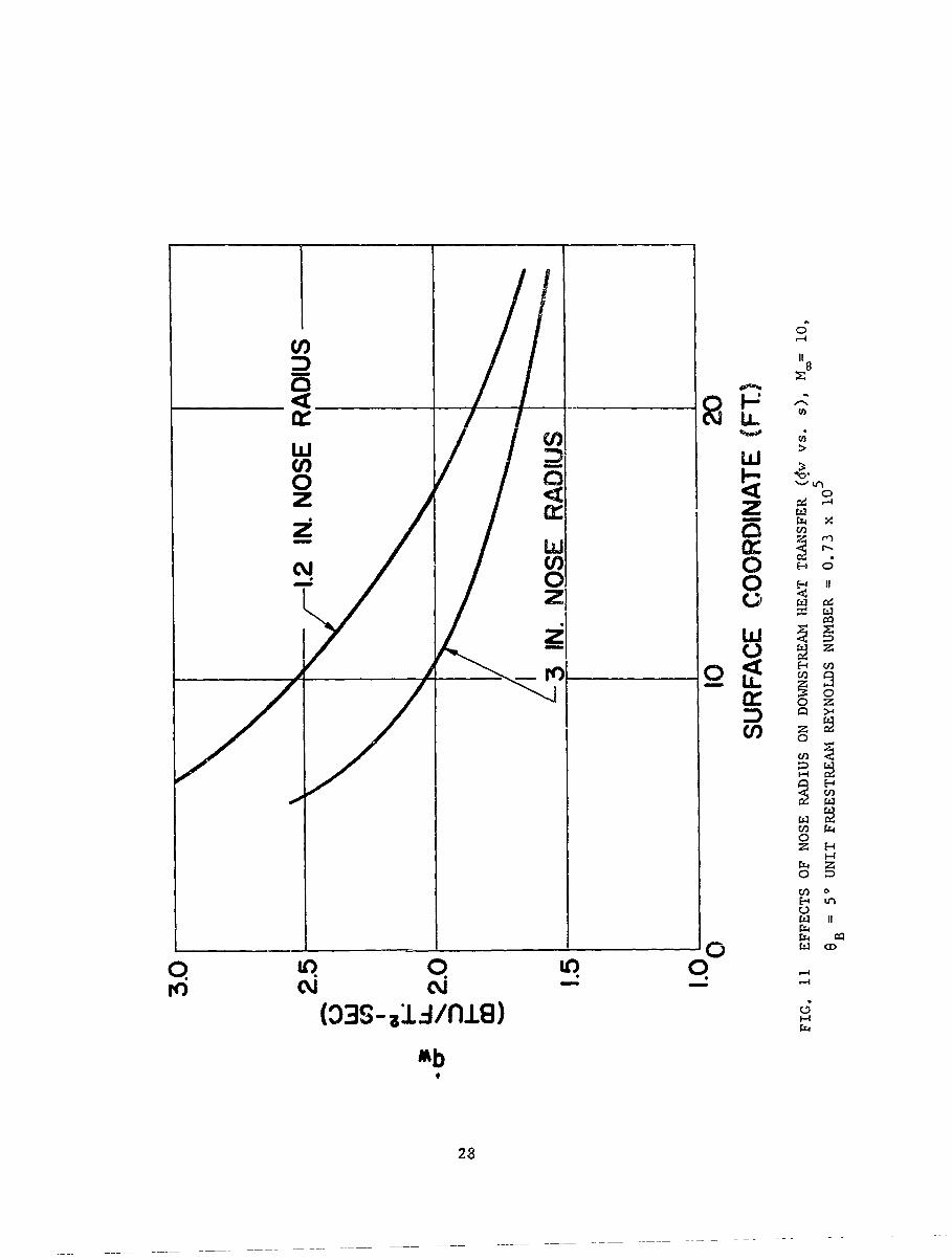
11 Effects of Nose Radius on Downstream Heat Transfer (qi vs. s),
M = 10, e - -. .... FrQLrin Rtynoidb Liumuer = U.73CO B -5
x 10 .................................................... 28
12a Heat Transfer Parameter Nu/R eol ) 1/3 as a Function of the
Similarity Parameter S/R ecoI / 3 , 8 B = 50 ...................... 29
12b Heat Transfer Parameter Nu/(R eol )1/ 3 as a Function of the
Similarity Parameter S/R , 1/3e 5B = 10. .0......................
12c Heat Transfer Parameter Nu/(Reol) I/3 as a Function of the
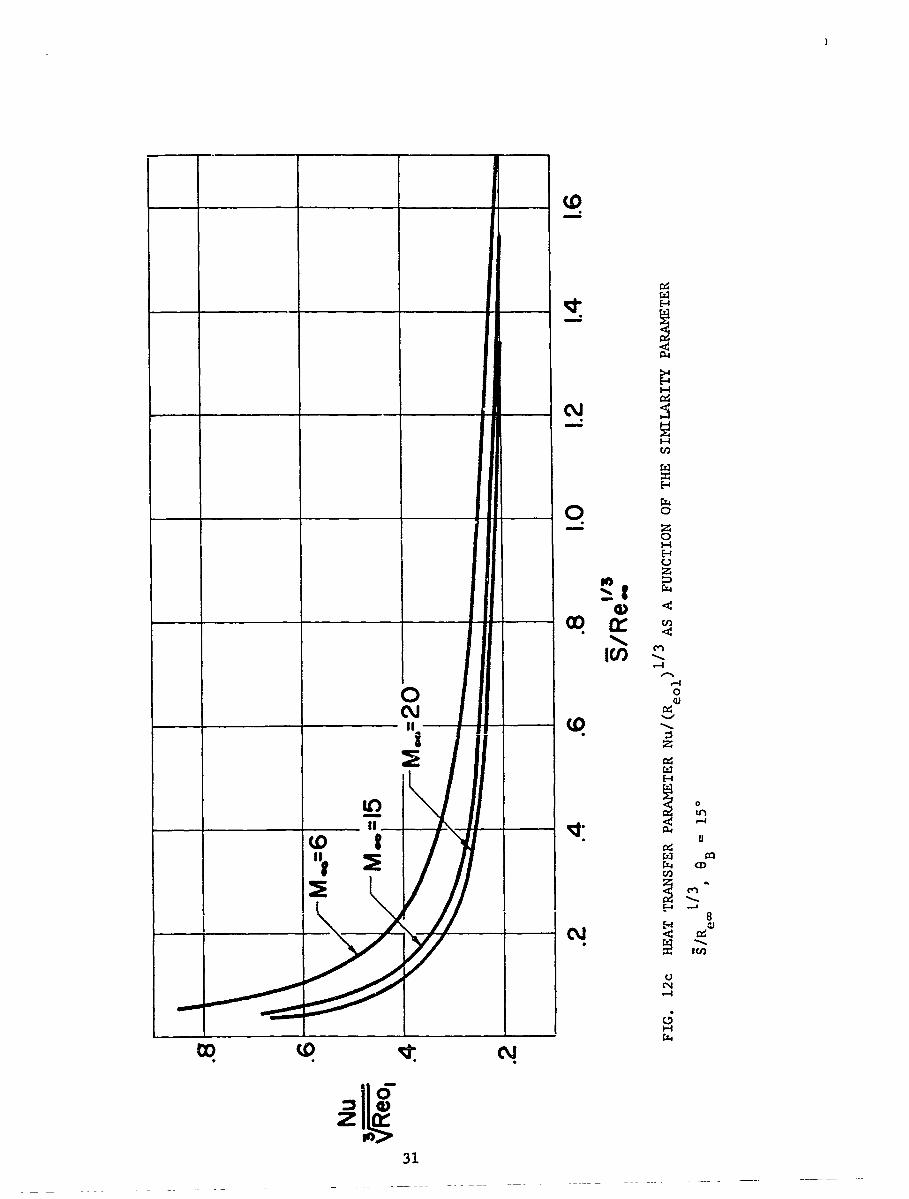
Similarity Parameter S/Re 1/3, eB = 150 ..................... 31
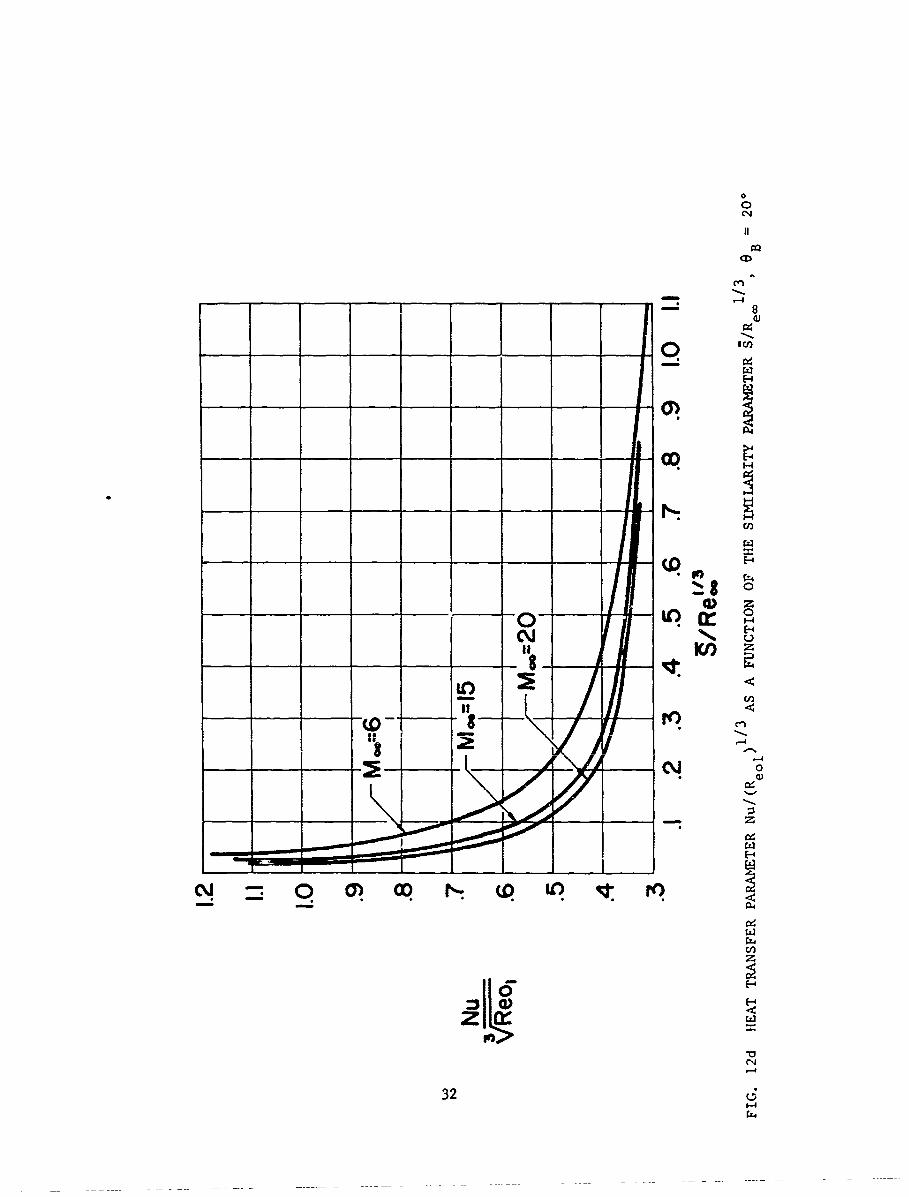
12d Heat Transfer Parameter Nu/(R 1eo)1/3 as - Function of the
Similarity Parameter S/R .1/3, eB = 200 ..................... 32
vi
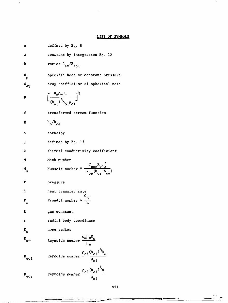
LIST OF SYMBOLS
a defined by Eq. 8
A constant by integration Eq. 12
B ratio: R e/Reo 1
C specific heat at constant pressure
CdT drag coefficient of spherical nose
(hol ) Po P'o i
f transformed stream function
g h /ho oe
h enchalpy
j defined by Eq. 13
k thermal conductivity coefficient
M Mach numberC R qupoe oqw
N uNusselt number koe (h-h)
P pressure
heat transfer rateC.
P Prandtl number =r k
R gas constant
r radial body coordinate
R nose radius0
R _____Ro
ec Reynolds number
p , (h o)RReo I Reynolds number o1 ol
pol(hol) s
Reo Reynolds number01oeos 1101
vii
' distance along body surface from the stagnation point
S S'/R0
S distance along body surface measured from the sharp cone vertex
S/R
Sc swallowing distance
y ratio of specific heats
6 conical shock anglec
6 normalized boundary layer displacement thickness, 6/R 0
TLees transverse coordinate
e B cone half angle
normalized momentum thickness, e/R 0
pdynamic viscosity
p density
Subscripts
o stagnation conditions
e local conditions at boundary layer edge
c inviscid sharp cone conditions
Cfreestream conditions
1 conditions behind normal shock
s conditions corresponding to blunted cone shoulder
T conditions corresponding to boundary layer transition
w conditions at the body surface
cverbar denotes non-dimensionalization with respect to R or
freestream conditions
viii

INTRODUCTION
The entropy layer caused by the curved shock associated with nose blunting
provides a rotational external stream through which the boundary layer develops.
1As pointed out by Ferri and Libby the interaction between the rotational
external flow and the viscous flow ntar the wall may in some instances invalidate
the classical boundary layer approach This interaction effect becomes important
when the vorticity of the external stream is on the same order as the average
vorticity in the boundary layer (Ref 2) These conditions may exist for
example in the combination of low Reynolds number (low boundary layer vorticity)
and high Mach number (high external stream vorticity due to the highly curved
shock). This problem was investigated for heat transfer in the nose region in
Ref. 3 and it was found that a modification of the classical boundary layer
external boundary conditions was necessary to satisfactorily describe the flow,
even at very low Reynolds numbers At higher Reynolds number the effect of the free-
stream vorticity on the boundary layer profile becomes negligible and the
results of a classical boundary layer analysis may closely approximate the
true physical situation. For this set of conditions, calculation of heat
transfer and shear can be carried out r. a consistent scheme accounting for
the variation of the boundary layer edge conditions caused by the curved
shock. The additional simplifying assumption of boundary layer similarity
can be introduced when the analysis concerns the case of the highly-cooled
4wall. Indeed, for this case Lees showed that the velocity gradient term in
the transformed boundary layer equation may be neglected and the resulting
equation is the Blasius equation for the flat plate. In reference 5, exactly
this type of analysis is carried out to determine the conditions at the edge
of the boundary layer. In the present report, the method is generalized and
extended to include the quantitative effects of shock curvature on the laminar
heat transfer.
1
*1
Fluid particles having crossed the curved shock at different shock
inclinations carry with them through the inviscid entropy layer different
entropies and stagnation pressures. By identifying the streamline shock
coordinate and the body coordinate corresponding to the point at which the
streamline enters the boundary layer, the conditions at the boundary layer
edge can be determined. Experimentai evidence shows that the static pressure
on the conical surface of blunted cones is virtually constant at distances
greater than 20 nose radii downstream of the shoulder and is equal to the
sharp cone value. Use is made of this observation in the calculation of the
boundary layer edge conditions.
The author takes this opportunity to thank Dr. V. Zakkay for suggesting
this investigation and for his guidance in the work reported here.
2

METHOD OF ANALYSIS
The mass flow through the laminar boundary layer on an axisymmetric
body at zero angle of attack is given by,6
= 2rrjp udy' (1)0
intodLJuciL Lees variauies,vVPeUer j .. .d /(2
(2 S ) o e
I
SL jUepe IL er ds (3)0
(1) becomes
= 2rr (2S L)f (I ) (4)
considering streamtubes entering the shock at a distance y from the axis of
symmetry (Fig. 1) 2(2 L) f ( e)
y =CPC (5)u p
introducing the non-dimensional variable S defined by
S = L (6)
S u 4p R3
the non-dimensional shock coordinate y = X- is given byR0
-=r 3/2
y L 2 f (i e)R coS]
where_u=p Ro
R -
defining the coefficient a 3/2f (8)f( le)Recoj(8
- = a 1/4 (9)y aS(9
s S((Za)4 = ' = J Uee'e~ d + f u e e e
d (10)
a S Jup s eee
s5
coteB I
( ) e Ue- fUe dS + Ue eer-ds' (1.i)0 0 0
for S > coteB
(Y-)4 = JUp ;? sineBdS + A (12)0
For blunted cones of a given cone angle and freestream Mach number, the
function U Pe_ along the boundary layer edge is a function of the inclinationeee
of the shock. Assuming similar shock shapes for similar bodies and that the
pressure on the conical portion of the body (S > coe B) is constant and equal
to the sharp cone pressure, uepe e is a function only of the non-dimensional
shock coordinate y.
UePe~e = J (y) (13)
4 3 j ()sine j d (a4 = B d9 /14)
A technique for evaluating (14) graphically has been given by Rubin 7 to
obtain the edge conditions as a function of S. With the equation in this
form, real gas effects may be computed by evaluating j(y) using the real gas
oblique shock relations and the real gas effects in the expansion to the
inviscid cone surface. The following analysis assumes a perfect gas with
y = 1.4.$3 3 1 -3- cOt3eB
-= 1 n e+ R(15)2 Si (e) Y G Re
YS
The first term on the right hand side of (15) is an exact form of the
similarity parameter for the swallowing process. If the pressure distribution
on the spherical cap is assumed to be a modified Newtonian and is used in
computation of the value of Ys; it is found that for Re, > 10,000, the effectscot 3 eB
of ys and are negligible for eB = 50 to 200. Thus, the form of theeco
similarity parameter becomes,
4
13 1/4 _
Rm 2 i 2- dy (16)
or its equivalent forms S/R 1/3 R 1/4 where,
= RI1/4F Sp_. 1i / 4
1/4 LR 4Re o
eos
If Eq. (16) is integrated, the functional relationship between S and y is
established and the conditions at the boundary layer edge are expressible
directly as functions of the surface coordinate S or for general freestream
- 1/3conditions as functions of the similarity parameter S/R 1/3 The integration
of (16) is performed numerically using the correlated shock shape of Ref. 8.
1424 e~c 5 ( x \10.46
y = 1.424coseBCDT' \os)0
where C = 2.0 - cos eBCDT
The value of y where the shock takes the conical angle
6c = arc sinE-[4.0 + 1.01 (M sine B - 3.43)] }
is taken as the upper limif of integration y and i3 given by:
C = C~eB{ 984 E l0.426
ccComparison of this shock shape with photographs of the shock show very
good agreement with the actual shock in the region of interest 0 :9 y < Yc"
The results of this computation expressing the boundary layer edge
conditions as functions of the similarity parameter for several values of
cone angles and freestream Mach numbers are given in Figs. 2 and 3.
For lower Reynolds number flow and for bodies of large nose blunting
where the region S cot8 B is of interest, the similarity parameter S/Reo 1/3
5
breaks down. In this case, if the shock shape is known, Eq. (9) may be
integrated from the stagnation point along the body with the streamline
stagnation pressure determined by iteration from the previous point.
Having established the boundary layer edge conditions downstream of the
- 1/3shoulder to be functions of the parameter SiRe I / , the assumption of similar
*-W
boundary layer profiles enables the boundary layer properties 6 , e, R to
be expressed in a general way, applicable to a family of blunted conical
bodies. From the standard definitions, obtain,
-* _(S4 -- L1 e6 = R per 2 [f '- ( f ,)2dLj (18)
Re "(2S")f J[f -(f djd (19)
Re = R ee 0
S(2S~)~ 1, 20R- R ,. If'(f')2 ]d (20)
From (18), (19) and (20) it can be established that the boundary layer
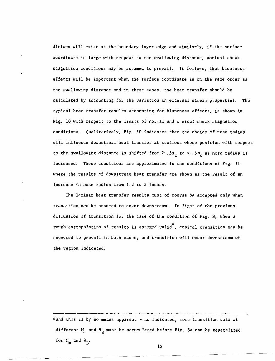
-. 1/3 R1/3 -2/3parameters 6 R e/, 6R 3 R -eRe / are functions of the similarity
- 1/3parameter S/R 1/3 The results of numerical calculations expressing these
parameters as functions of the similarity parameter for several values of
freestream Mach numbers for a cone of half angle 150 are given in Figs. 4,
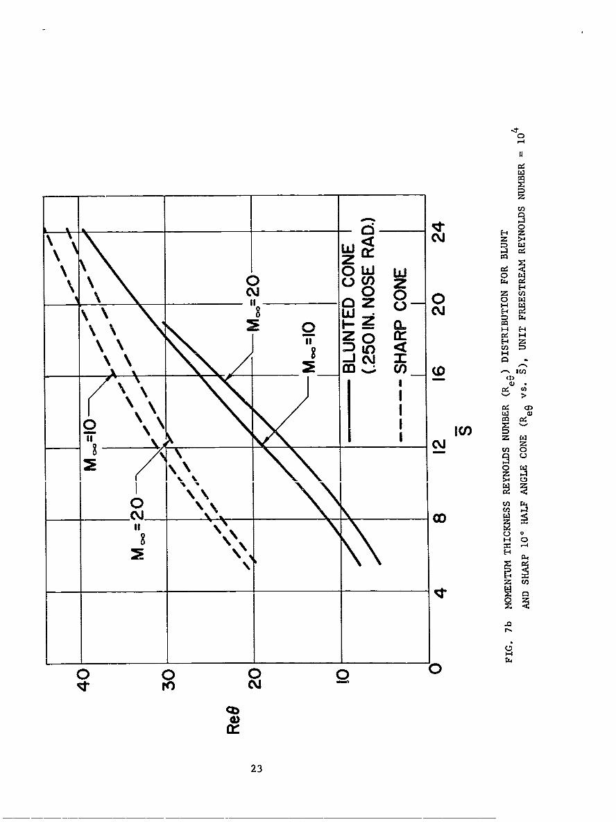
5 and 6. The effect of blunting on Ree at different R is shown in Figs.
7 and 8.
At hypersonic speeds, where effects of the external stream gradients
on stability are as yet uncertain, the knowledge of Rex or R alone along
the body surface may not be enough to predict the onset of transition. As
9pointed out most recently by Stetson and Rushton , when transition appears
on the body between the shoulder and the swallowing distance, Re8T will
vary from a blunt body value of approximately 340 to a conical body value
of approximately 700. From shock tunnel experiments 9 conical transition
6

will occur when R < 340 at S Z .3S and blunt body transition will occur
when Ree > 340 at Sc5 .035 .
With the generality afforded by the results in Fig. 6, the range of
R for which conical and blunt body transition will occur can be found as
a function of unit freestream Reynolds number and degree of blunting. The
results are given in Figs. 8a and Sb; for thp nocific family of S ° blunted
cones at M = 5.5. The extension of these results to include the effects of
cone angle and Mach number must necessarily await additional experimental
transition data at different Mach numbers and cone angles.
Fig. 8b indicates that the effects of bluntness on transition are
very important in the design of hypersonic flight vehicles. For example,
at Mach 5.5 and 8B = 80 at 100,000 ft., a vehicle with a three inch nose
radius will undergo transition at some point along the surface between 4.6
ft. and 20.8 ft., corresponding to R of 340 and 680 respectively. Therefore,
the assumption of one type of transition for a body having a surface length
of between 4 and 20 ft. can result in error over a large part of the conical
surface.12
Nagamatsu et al report transition on a blunted cone of .2 in. radius
50 cone half angle, M = 11 with the stagnation conditions, T = 1400*K,O0
P = 1300 psia. Transition is observed to occur at a distance of 18.72 in.0
from the cone tip. With the same conditions but at P = 890 psia, no0
transition is observed within the distance of 45.38 inches. Determination
of the R for these conditions indicates that at P = 890 R is below
700 for the entire length and since the flow is laminar, it may be assumed
that these conditions are in the conical transition region. At 1300 psia,
R e is about 340 at 18.72 in from the tip, where transition is observed.
These calculations lead to the conclusion that in going from R- = .8 x 104eco
5to R e = .13 x 10 , the transition moves from conical to blunt body type.
This suggests, moreover, that the influence of Mach number and cone angle
on the type of transition is significant.
7

By assuming a linear Mach number variation along the conical surface,
Zakkay and Krause5 obtained the expression:
. 2_y -4R 1/3_-3 R._O jO(21)
Sc = [2 % Pc ( 3 Mc+Ms) f2 (I) s in 2 (21)
for the extent of the bluntness effects (i.e. the swallowing distance).
Cast in the form of the present analysis, this expression is:
S 1.5M 4 .11/31c [J (22)
Re 3 -Pr2 (ssi3 (3+eco B t~c+s
P
or dimensionally as
1/3 p 4l/3
4/3 2/3 =(23)
R4/3 (puP s) f2 (r s in s e0
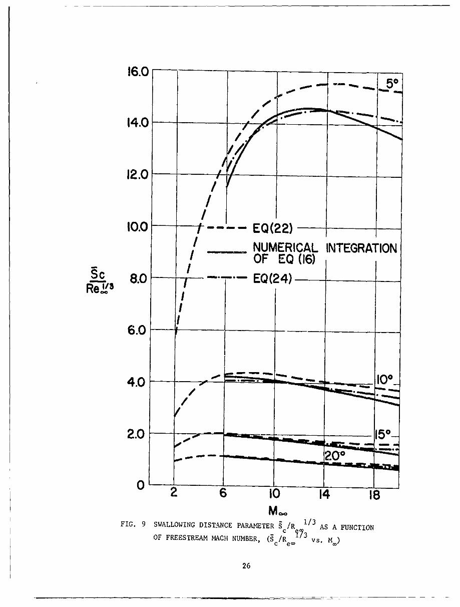
Eq. (21) or (22) can be used to conveniently express the swallowing distance
as a function of the degree of blunting and freestream conditions. The
results for several cone angles are given in Fig. 9 in comparison with the
swallowing distance computed by numerically integrating (16) to the upper
limit Yc. Where yc is defined as the non-dimensional shock coordinate at
which the shock is nearly conical. Specifically, Ref. 9, uses the value of
Yc where the shock angle yields a Mach number on the inviscid cone of .95
M . An examination of the integrand of (16) indicates that the value ofc
c e/R 13 is strongly dependent on the value of Yc" The critical nature
of the value of yc is evident in the approximate form of the swallowing
distance parameter given by Eq. (22) where yc appears as the fourth power
relative to the other terms in the expression. Physically this expresses
the fact that most of the flow in the boundary layer near the swallowing
point has entered the shock at values of y near y c This implies that
the shape of the shock in the yc region is more important than the shape
8

of the shock at smaller values of y, for the determination of S c Thus, if
the shock is assumed to have the constant conical angle throughout (Ms
replaced by M in Eq. 22), and the correct value of y from the curvedC
shock retained, the approximate Eq. 22 simplifies to:
I c J 4- 1' PI
1/3= L p / f ) B (24)
R eco C/ PCf2(1) s n0B (4Mc
the results shown on Fig. 9 indicate that Eq. (24) approximates the shock
shape more closely in the region near y than does Eq. (22) (since the Mach
number will approach M asymptotically, as shown in Fig. 2). The importancec
of approximating the shock shape near yc rather than an overall approximation
is shown in Fig. 9 where the approximation (22) is seen to be in closer
agreement with the numerical integration. The role of the shock shape in
the region near yc in the calculation of Sc lies at the root of the descrepancy1A 11
between the results of this method and the momentum integral method of Wilson in
9

HEAT TRANSFER
The variation of the heat transfer along the conical portion of the body
is due to the local surface coordinate and the external stream conditions at
the boundary layev edge affecting the physical plane temperature gradient at
the wall. The effect of the external stream vorticity on the boutndary layer
profile is assumed to be nnaligeibl due to the Reynn1d nimber_ to Which the
present analysis is applied. The heat transfer is calculated in the non-
dimensional form Nu/(R eol ) where the Nus.elt number and the Reynolds number
are defined with respect to the normal shock stagnation conditions.
Nu = pe q (25)koe (hoe-h ow)
(h oe)kP olRReol oe (26)
The heat transfer parameter Nu/(R in terms of the analysis becomes,eo l nt
Nu/(R = .333DP 1/3 Uepeer (27)eol r
where ucopj, -
(h l) k P01%l
and P is an average Prandtl number across the boundary layer. In obtainingr
the form of Eq. (24), the conclusion of Lees4 for the cold wall
W -1/3gw = .47P1w. r
is used.
The results of the numerical evaluation of (25) for a cone of 150 half
angle at freestream Mach number of 20, is presented in Fig. 10. Shown also,
are the limiting values obtained by assuming normal shock and conical shock
conditions to exist at the boundary layer edge.
10

The influence of shock curvature on heat transfer as illustrated in Fig. 10
for conditions of M00 = 20, R e(per ft.) = 1.0 x 10⁵ is representative of the
quantitative influence of shock curvature on the heat transfer to the portion
of the body downstream of the shoulder.
Examining the variable terms appearing on the right hand side of (25)
- - - 1/3u eP JL f (s /R )
- 1/3 - 1/3r = Re e(I )sine
R
e _ y(s/Re1/323/2f e)
Eq. (25) is seen to have the form,
Nu R -1/6 /( 3IR 1/3 (28)(Reo) e= e
eo
where f, '/R 1/3
A. I 3 312 fs( a-F1 (s'/Re) = 333DP ' "sine 2/f RV-
• r B R1/3 /R 1/3
Thus, the heat transfer parameter Nu/(R e) is a function of the similarityeo a 1/4
parameter s/R e/3 and by Eq. (17) also of the similarity parameter S/R eos/41/3e
The value of Nu/(R eo) as a function of S/R e/3 represents the effect of
the shock curvature on the laminar heat transfer along the conical surface for
a family of blunted cones. The heat transfer calculations for a family of
cones at various values of the freestream Mach number are presented in Fig. 12.
Calculation of the heat transfer on the conical part of the body based on
c.................. st --ream stagnation properties corresponding to normal sIIIoc
or conical shock conditions can be made in the cases of high R or low Reo
or respectively. Essentially, if the surface coordinate is small with
respect to the swallowing distance (high R e), normal shock stagnation con-
11
ditions will exist at the boundary layer edge and similarly, if the surface
coordinate is large with respect to the swallowing distance, conical shock
stagnation conditions may be assumed to prevail. It follows, that bluntness
effects will be important when the surface coordinate is on the same order as
the swallowing distance and in these cases, the heat transfer should be
calculated by accounting for the variation in external stream properties. The
typical heat transfer results accounting for bluntness effects, is shown in
Fig. 10 with respect to the limits of normal and c nical shock stagnation
conditions. Qualitatively, Fig. 10 indicates that the choice of nose radius
will influence downstream heat transfer at sections whose position with respect
to the swallowing distance is shifted from > .5s to < .5sc as nose radius is
increased. These conditions are approximated in the conditions of Fig. 11
where the results of downstream heat transfer are shown as the result of an
increase in nose radius from 1.2 to 3 inches.
The laminar heat transfer results must of course be accepted only when
transition can be assumed to occur downstream. In light of the previous
discussion of transition for the case of the condition of Fig. 8, when a
,rough extrapolation of results is assumed valid , conical transition may be
expected to prevail in both cases, and transition will occur downstream of
the region indicated.
*And this is by no means apparent - as indicated, more transition data at
different M. and 6B must be accumulated before Fig. 8a can be generalizedB"B
for M, and 812
RESULTS AND CONCLUSIONS* (Ro)
The general boundary layer parameters 6 , B, Re, Nu/(R ) are found
and presented for a family of correlated cones and shock shapes at Mach numbers
from 5 to 20, for distances along the conical surface corresponding to the
swallowing distance. The effects of nose bluntness on transition and heat
transfer are judged in terms of the swallowing distance, for which a
simplified approximation is presented (Eq. 24). Based on the general Re8
results along the conical surface, regions cf R for which conical transition
(ReeT - 700) and blunt body transition (Re6T = 340) can be expected is presented
in Fig. 8a. For family of 80 cones at M. = 5.5 the reversal region will occur
5 6for .216 x 10 < R < .26 x 10 The need for additional experimental studies
to extend the results to account for MO and cone angle effects on transition
is indicated. The investigation of heat transfer accounting for shock
curvature effects shows that the laminar heat tranrsfer to the conical part
of the body can be influenced by the degree of nose blunting when the nose
radius is increased enough to shift that part of the body from > .5s to
< .5sC .
13

REFERENCES
1. Ferri, A. and Libby, P. A., "Note on an Interaction between the Boundary
Lay.r and the Inviscid Flow," j. Aero. Sci., 21, 2, P. 130, February 1954.
2. Ferri, A., "Some Heat Transfer Problems in Hypersonic Flow," Reprinted
from Aeronautics and Astronautics, Pergamon Press, New York, pp. 344-377,
1960.
3. Ferri, A., Zakkay, V. and Ting, L., "Blunt Body Heat Transfer at Hypersonic
Speed-and Low Reynolds Numbers," Polytechnic Institute of Brooklyn PIBAL
Report No. 611, June 1960.
4. Lees, L., "Laminar Heat Transfer over Blunt-Nosed Bodies at Hypersonic
Flight Speeds," Jet Prop., Vol. 26, No. 4, pp. 259-269, April 1956.
5. Zakkay, V. and Krause, E., "Boundary Conditions at the Outer Edge of
the Boundary Layer on Blunted Conical Bodies," AIAA Journal, Vol. 1,
No. 7, pp. 1671-1672, 1963.
6. Burke, A. F. and Curtis, James T., "Blunt-Cone Pressure Distributions
at Hypersonic Mach Numbers," j. Aerospace Sci., Vol. 29, 1962, pp. 237-238.
7. Rubin, I., "Shock Curvature Effect on the Outer Edge Conditions of a
Laminar Boundary Layer," AIAA Journal, 1, pp. 2850-2852, 1963.
8. Klaimon, J. H., "Bow Shock Correlation for Slightly Blunted Cones," J.
Aero. Sci., Vol. 1, No. 2, February 1963.
9. Stetson, K. F. and Rushton, G. H., "A Shock Tunnel Investigation of
the Effects of Nose Bluntness, Angle of Attack and Boundary Layer
Cooling on Boundary Layer Transition at a Mach Number of 5.5," AAA
Paper No. 66-495, June 1966.
10. Wilson, R. E., "Laminar Boundary - Layer Growth on Slightly - Blunted
Cones at Hypersonic Speeds," J. Spacecraft and Rockets, 2, pp. 490-496,
1965.
11. Wilson, R. E., "Laminar and Turbulent Boundary Layers on Slightly-
Blunted Cones at Hypersonic Speeds," NOLTR 66-54, 1966.
14

12. Nagamatsu, H. T., Graber, B. C. and Sheer, R. E., "Roughness, Bluntness,
and Angle-of-Attack Effects on Hypersonic Boundary Layer Transition,"
(1966), J. Fluid Mechanics, Vol. 24.
13. Sims, J. L., "Tables of Supersonic Flow around Right Circular Cones at
Zero Angle of Attack," 1964, NASA SP-3004.
14. Minzner, R. A., Champion, K. S. W., Pond, H. L., "The ARDS Model
Atmosphere," 1959, Air Force Cambridge Research Center, TR-59-267,
August 1959.
15. Reinecke, W. G., "Charts for Use with Hypersonic Air Wind Tunnels,"
(1964) ARL 64-56.
15

0C
-~E-4
>4
4 t(4
E-4
00
04
H-
0 C.,
16:

£0 OD0 M ,
0" 1i-CD4
0
w Nz
'-4
0 ot
01-E-4
E-4
OD!
0
0 000000i (D6
17

-4
ODI
>
) 0
F-4
P44ON %L
0 C/0
0 0 0 0 0,
C d j (64: N
184

CCzl
rz~~0
00
0
1-4
z
-4
1-4
0 -0
194

-0
_ _ _ __ _ _ _co
z
- -4
q* *jj 0(DD
'!7
20
0H
z
04 C)
1~ U0
4r)
flj~ICI)
-4
0AA
4)4)4
21

0-4
0 z-A- oF-o
I-- O)-L Z H
oC -
0
0_ __4 C40r
E- C\I
z 0
--1 04
10~
00
22:
'-4
11
z
C~j z >4
z0
a z 2
a.__ 1-4 _-4
H -4
(00
00'C c
23-

BLUNT BODYRANSITION
"vRVRSAL EFFECT" R .26 0 IO
L
CONICAL BODYTRANSITION(ReOT =680)
1 3 4 5 6 7 8R0 NOSE RADIUS (INCHES)
24
FIG. 8a REGIONS OF CONICAL AND UJUNT BODY TRANSITION IN TERMS OFUNIT FREESTREAM REYNOLDS NUMBER AND NOSE R-ADIUS, rut, = 8,CONE HALF ANGLE (0B) = 5.50

160 -CONICAL BODY- oTRANSITIONrleaT -KOV
1401
120
-
I TRANSITION
I ReGT:3404011i
NOSE RADIUS (INCHES)FIG. 8b REGIONS OF CONICAL AND BLUNT BODY TRANSIrION IN TERMS
OF FLIGHT ALTITUDE AND NOSE RADIUS, M_= 8, CONE HALFANGLE (n .)
25
14.0-_ _
12.0
100 t--EQ(22)/ NUMERICAL INTEGRATIONI OF EQ (16)
9c 8.0-- EQ(24)Re,',3
6.0 _ _
4.0 "No
2.0 50
Mce
FIG. 9 SWALLOWING DISTANCE PARAMETER S c /R 1/3 AS A FUNCTIONOF FREESTREAM MACH NUMBER, (9 cReo73v.M)
26

z0 E-
D400-0 I Jz-00 0
4 2IC0 z 00 Oj= e(D-.C
40 2 ZHF;Z lW(.) z CD*~
_- - 0
Z 0 <O0-OFW U)%WO 0oz 0-
Wc /D< %-. _ 0
o
E-4
co r- c N -
00
1-4
27
Cf/00
4 __
w _ w0 0w
- )0 U<ci
cfi)
r1 z
0 =cn H
rZIo14
-4L
W C\J-
(33S-a~i/me)u
mb
28

-E-00
ODI
1 0
aca-4
-4 8
E-4D
-4
0 0
29

q~I--
00
00
00
rq4
0o30t~
;14
0
4-4
z44
-4
-4
00
0
ZI 6'crH
___ v) b_____ ___ _ ___31
CN
rn
-~ 8
I rn
-- E-4
I00CCl)
_ _ _ _vJ _ _ _ _ _ _I
Ui)
32

Unclassified
Security Classification
DOCUMENT CONTROL DATA- R&D(Security claseficatlon of title, body of abetract and indexing annotation muet be entered when the overall report Is claseelled)
1. ORIGINATING ACTIVITY (Corporate author) 2a. REPORT SECURITY C LASSIFICATION
New York University Unclassified
Bronx, New York 10453 2b GROUP
3. REPORT TITLE
EFFECTS OF NOSE BLUNTNESS ON THE BOUNDARY LAYER
CHARACTERISTICS OF CONICAL BODIES AT HYPERSONIC SPEEDS
4. DESCRIPTIVE NOTES (Typo of report and Inclusive datee)
Interim Report - November 1966
S. AUTHOR(S) (Laset name. first name, Initial)
Rotta, Nicholas, R.
6. REPORT DATE 7a. TOTAL NO. OF PAGMS 7b- NO. OF RKF8
November 1966 41 15So. CONTRACT OR GRANT NO. Ia. ORIGINATOR'S REPORT NUMUR'S)
NONR285 (63) NYU-AA-66-66b. PROJECT NO.
RR 009-02-01 1_C. 9b. OTHR RPORT NO( (Any Other number@ Mat may be assignedthise report
d. none
10. AVA IL ABILITY/LIMITATION NOTICES
Distribution of this document is unlimited
11. SUPPLEMENTARY NOTES 12. SPONSORING MILITARY ACTIVITY
Department of the Navy
Office of Naval Researchnone Washington, D. C.
13. ABSTRACT
The effect of nose blunting on the boundary layer characteristics over theconical part of a body is investigated. The boundary layer parameters"* (R
6, , R e, NU /(R are found as functions of the similarity parameter
- 1/3S/R eco / , and the boundarylayer equations are integrated numerically. The
resulting profiles are general, being independent of unit freestream Reynolds
number and nose radius. The effect of bluntness on transition is investigated.
Using the variation of Reynolds number based on the momentum thickness in the
swallowing region as an indicator, the type of transition likely to occur, i.e.,
blunt body ReeT ! 340 or conical transition R eT ; 700, is examined. The range
of unit freestream Reynolds number for which conical transition will occur is
identified specifically for the family of blunted conical bodies of 80 halfangle at Mach 10. Based on the transition data, the heat transfer is
calculated for regions of the swallowing process for which the boundary layer
is laminar.
The results indicate a reduction of heat transfer is associated with nosebluntness and can be significant downstream of the nose region if the body
node radius is chosen to make the swallowing distance approximately twice
that of the body surface length.
DD ,'°N6 1473 UnclassifiedqeCu.aaa +Cao -
Unclassified
Security Classification_ _ _
14. LINK A LINK B LINK C --
ROLE WT ROLE wT ROLE WT
bluntness effects
laminar boundary layer
conical bodies
hypersonic
vorticity interaction
heat transfer
INSTRUCTIONS1. ORIGINATING ACTIVITY: Enter the name and address imposed by security classification, using standard statementsof the contractor, subcontractor, grantee, Department of De- such as:fense ativity or other organization (corporate author) issuing (1) "Qualified requesters may obtain copies of thisthe report. report from DDC."
2a. REPORT SECURTY CLASSIFICATION: Enter the over- (2) "Foreign announcement and dissemination of thisall security classification of the report. Indicate whether"Restricted Data" is included. Marking is to be in accord- report by DDC is not authorized."ance with appropriate security regulations. (3) "U. S. Government agencies may obtain copies of
this report directly from DDC. Other qualified DDC2b. GROUP: Automatic downgrading is specified in DoD Di- users shall request throughrective 5200. 10 and Armed Forces Industrial Manual. Enterthe group number. Also. when applicable, show that optional.. rk:ng-s have been used for Group 3 and Group 4 as author- (4) "U. S. military agencies may obtain copies of thisized report directly from DDC. Other qualified users3. REPORT TITLE: Enter the complete report title in all shall request throughcapitdl letters. Titles in all cases should be unclassified.If a maningful title cannot be selected without classifica-
:" ow title classification in all capitals in parenthesis (5) "All distribution of this report is controlled. Qual-immcdi;.tely following the title. ified DDC users shall request through
4. DFSCRIPTIVE NOTES: If appropriate, enter the type of bto
repc,rt. e.g.. interim, progress, summary, annual, or final. If the report has been furnished to the Office of TechnicalGive tne in.lus ave dates when a specific reporting period is Services, Department of Commerce, for sale to the publ.c, indi-c ,wred. cate this fact and eracr the price. if known.
5. AUT[ ,IOR(S): Enter the name(s) of author(s) as shown on I L SUPPLEMENTARY NOTES: Use for additional explans-r in the report. Entet lest name, first name. middle initial, tory notes.
If .niitar*, show rank and branch of service. The name ofth: principal .:%thor is an absolute minimum requirement. 12. SPONSORING MILITARY ACTIVITY: Eter the name of
the departmental project office or laboratory sponsoring (pay-b. REPORT DATE. Enter the date of the report as day, 'ng for) the research and development. Include address.niath, year. or month, year. If more than one date appearson the report, use date of publication. 13 ABSTRACT: Enter an abstract giving a brief and factual
summary of the document indicative of the report, even though7a. TOTAL NUMBER OF PAGES: The total page count it may also appear elsewhere in the body of the technical re-siculd follow normal pagination procedures, i.e.. enter the port. If additional space is required, a continuation sheet shallnumber of pages containing information, be attached.
6. NUMBER OF REFERENCES Enter the total number of It is highly desirable that the abstract of classified reportstefe:ences cited in the report. be unclassified. Each paragraph of the abstract shall end with8a. CONTRACT OR GRANT NUMBER: If appropriate, enter an indication of the military security classification of the in-the applicable number of the contract or grant under which formation in the paragraph, represented as (TS). (S). (C). or (U).the report was written. There is no limitation on the length of the abstract. How-
8b, 8c, & Ed. PROJECT NUMBER: Enter the appropriate ever, the suggested length is from 150 to 225 words.military department identification, such as project number,subproyet.t number system numbers, task number, etc. 14. KEY WORDS: Key words are technically meaningful terms
or short phrases that characterize a report and may be used as9a ORIGINATOR'S REPORT NUMBER(S). Enter the offi- index entries for cataloging the report. Key words must becial report number by which the document will be identified selected so that no security classification is iequired. Identi-and controlled by the originating activity. This number must fiers, such as equipment model designation, trade name, militarybe unique to this report. project code name, geographic location, may be used as key
9h. 01 HER REPORT NUMBER(S)- If the report has been words but will be followed by an indication of technical con-assigned any other report numbers (either by the originator text. The Assignment of links, roles, and weights is optional.or by the sponsor), also enter this number(s).
10. AVALLABILITY/LIMITATION NOTICES Enter any lira-itations on further dissemination of the repor:, other than those
DD 1473 (BACK) Unclas ified .....DD JA0 ___,_ , unI sI I_ I __II__I