
First instability of the flow of shear-thinning and shear ...

1
Effects of shear thinning on migration ofneutrally buoyant particles in pressure driven flow
of Newtonian and viscoelastic fluids
by P. Y. Huang and D. D. Joseph
Department of Aerospace Engineering and Mechanics and the Minnesota Supercomputer Institute,University of Minnesota, Minneapolis, MN 55455, USA
January 1999
Abstract. The pattern of cross stream migration of neutrally buoyant particles in a
pressure driven flow depends strongly on the properties of the suspending fluid. These
migration effects have been studied by direct numerical simulation in planar flow. Shear
thinning has a large effect when the inertia or elasticity is large, but only a small effect
when they are small. At moderate Reynolds numbers, shear thinning causes particles to
migrate away from the centerline, creating a particle-free zone in the core of the channel,
which increases with the amount of shear thinning. In a viscoelastic fluid with shear
thinning, particles migrate either toward the centerline or toward the walls, creating an
annular particle-free zone at intermediate radii. The simulations also give rise to precise
determination of slip velocity distributions in the various cases studied.
________________________________________________________________________
1. Introduction
Pressure driven flow is one of the most common types of channel flow in industry,
especially the petroleum and coal industries. If the particles and suspending liquid have
different densities, settling or suspending occurs simultaneously with shear-induced
migration. The bulk flow also depends on the relative sizes of the buoyancy and shear
forces. Morris & Brady [1] performed numerical studies of the influence of particle
buoyancy in pressure driven flow of a suspension when inertia is neglected and compared
with experimental results. They found that shear induced migration in Stokes flows
competes with buoyancy effects, and concluded that the flow behavior depends strongly on

2
both the bulk particle volume fraction and the dimensionless gravitational parameter, but
only weakly upon the dimensionless channel width.
Most of the investigations in the literature focus on the effects of shear thinning
generalized Newtonian fluids or the effects of elasticity without shear thinning. Segré &
Silberberg [2] reported that in Newtonian fluids, neutrally buoyant particles migrate into a
thin annular region with maximum concentration being at a radial position of about 0.6 of a
pipe radius from the centerline. Karnis & Mason [3] studied the migration of spheres in a
pipe flow without inertia effects. They observed that neutrally buoyant spheres migrate
toward the pipe wall in a purely pseudoplastic fluid but toward the center region of lower
shear rate in a viscoelastic fluid with constant viscosity. In contrast, Gauthier, Goldsmith &
Mason [4] declared that particles migrate toward the region of highest shear rate in very
slow flows of pseudoplastic fluids. Subsequently, Jefri & Zahed [5] performed
experimental work on the elastic and viscous effects on migration of neutrally buoyant solid
spherical particles in plane Poiseuille flow. With low volume solid fraction and creeping
flow conditions, they found that the particles are in uniform distribution in a Newtonian
fluid but migrate toward the centerline in a non-shear thinning viscoelastic fluid. Recently,
Tehrani [6] reported an experimental study on the migration of proppant particles in
viscoelastic fluids used in hydraulic fracturing. He focused on elastic and shear thinning
properties of the suspending fluid and concluded that the flow behavior depends strongly
on both the elastic properties and shear rate gradient of the fluids.
Joseph [7] pointed out that the effect of shear thinning is to decrease the viscosity and
increase the shear rate at places of constant shear stress. In a viscoelastic fluid, the
increased shear rate amplifies the effect of normal stresses at places where the shear stress
is constant. This was confirmed by Huang, Feng, Hu & Joseph [8] in numerical
simulations of the motion of a circular cylinder in Couette and Poiseuille flows of an
Oldroyd-B fluid. Binous & Phillips [9,10] recently performed dynamic simulations of
particle motions in viscoelastic fluids. In their method, the suspending fluids were modeled

3
as suspensions of finite-extension-nonlinear-elastic (FENE) dumbbells. In this method, the
effects of elasticity are revealed clearly and are consistent with most of the experimental and
numerical results shown in literature. But the method is restricted to low Reynolds numbers
and constant shear viscosities. It does not include the effects of inertia and shear thinning.
Asmolov [11] studied the inertial lift on a particle in plane Poiseuille flows at large flow
Reynolds number but small particle Reynolds number. Using a matched asymptotic
expansions method to solve governing equations for a disturbance flow past a particle, he
found three major influence factors for the particle migration: channel Reynolds number or
the curvature of velocity profile, distance from the wall and slip velocity. There is not much
literature concerned with the isolated and combined effects of inertia, shear thinning and
elasticity.
In the present paper, we studied the effects of shear thinning on the migration of
particles in both Newtonian and viscoelastic fluids in a two dimensional channel. To make
the study more precise, we isolated and studied the effects of shear thinning with and
without elasticity while keeping the channel width, particle density and size unchanged. We
also studied the effect of shear thinning when the volume fraction of solids is increased by
increasing the number of particles in the computational cell, keeping all the other parameters
unchanged.
2. Governing equations and numerical methods
Experimental and mathematical analyses and numerical simulations are the three major
methods for studying multiphase processes. Experiments give scientists first hand
phenomena to study but are sometimes difficult to interpret because competing effects are
present. Mathematical analysis can simplify a specific problem and abstract single effects;
analysis is always desirable but more often than not is not possible. Here we employ direct
numerical simulation which allows us to solve hard problems numerically and to isolate
competing effects.
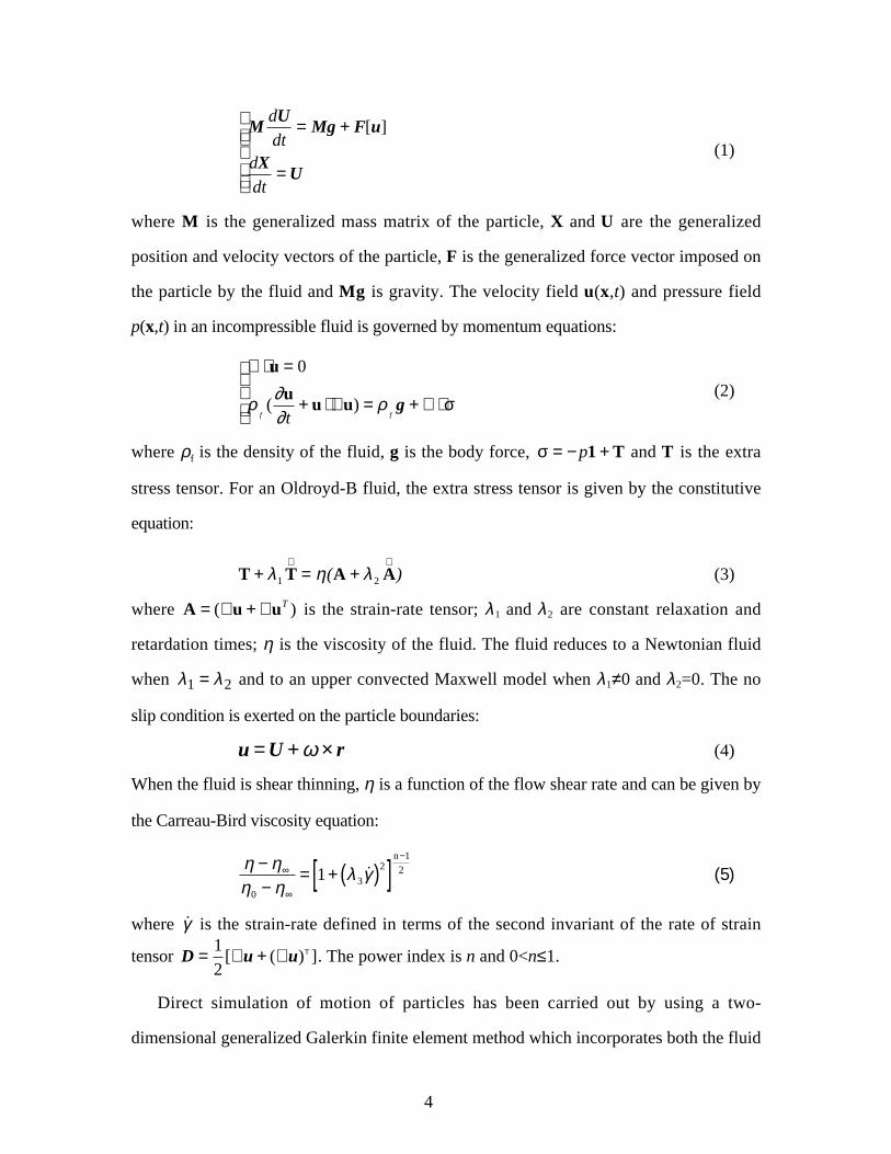
The motion of solid particles satisfies Newton's law:
4
MdUdt
= Mg + F[u]
dXdt
= U
(1)
where M is the generalized mass matrix of the particle, X and U are the generalized
position and velocity vectors of the particle, F is the generalized force vector imposed on
the particle by the fluid and Mg is gravity. The velocity field u(x,t) and pressure field
p(x,t) in an incompressible fluid is governed by momentum equations:
∇ ⋅ u = 0
ρf(∂u∂t
+ u ⋅ ∇ u) = ρfg + ∇ ⋅σ
(2)
where ρf is the density of the fluid, g is the body force, σ = −p1 + T and T is the extra
stress tensor. For an Oldroyd-B fluid, the extra stress tensor is given by the constitutive
equation:
T + λ1 T∇
= η(A + λ 2 A∇
) (3)
where A = (∇ u + ∇ uT ) is the strain-rate tensor; λ 1 and λ 2 are constant relaxation and
retardation times; η is the viscosity of the fluid. The fluid reduces to a Newtonian fluid
when λ1 = λ 2 and to an upper convected Maxwell model when λ1≠0 and λ2=0. The no
slip condition is exerted on the particle boundaries:
u = U +ω × r (4)
When the fluid is shear thinning, η is a function of the flow shear rate and can be given by
the Carreau-Bird viscosity equation:
η − η∞
η0 − η∞
= 1+ λ 3γ̇( )2[ ]n−1
2 (5)
where γ̇ is the strain-rate defined in terms of the second invariant of the rate of strain
tensor D = 12
[∇ u + (∇ u)T ]. The power index is n and 0<n≤1.
Direct simulation of motion of particles has been carried out by using a two-
dimensional generalized Galerkin finite element method which incorporates both the fluid

5
and particle equations of motion into a single coupled variational equation. An arbitrary
Lagrangian-Eulerian (ALE) moving mesh technique was used to compute the motion of the
particles. The modified code with EVSS (Elastic-Viscous-Split-Stress) scheme for solving
transient Navier-Stokes equations together with a moving finite element mesh can be used
to simulate the unsteady motion of the viscoelastic fluid and the solid particles directly. In
our implementation, the nodes on the particle surface are assumed to move with the
particle. The nodes in the interior of the fluid are computed using Laplace’s equation, to
guarantee a smoothly varying distribution. At each time step, the grid is updated according
to the motion of the particles and checked for element degeneration. If unacceptable element
distortion is detected, a new finite element grid is generated and the flow fields are
projected from the old grid to the new grid. In each time step, the positions of the particles
and grid nodes are updated explicitly, while the velocities of the fluid and the solid particles
are determined implicitly. Our grid system uses unstructured mesh triangular elements.
More details about the equations and numerical computations are given by Huang, Hu &
Joseph [12].
3. General conditions for the simulations
With the numerical package we developed, Particle-Mover, solid-liquid flow
problems can be simulated. Details may be found at the NSF Grand Challenge —
KDI/NCC Project Web site:
http://www.aem.umn.edu/Solid-Liquid_Flows/
together with video animations of the cases discussed in this paper.
The computational domain is a 2-D periodic channel of width W=10 cm and length
L=21 cm, as shown in figure 1. There are 56 solid particles initially distributed uniformly
in the channel (figure 2) and the volume fraction of solids is Cp = 0.21. The fluid density is
ρ f = 1.0 g⋅ cm−3 . The particles are neutrally buoyant circular cylinders (ρs = 1.0 g⋅ cm−3)
with diameter d=1 cm and are driven by a pressure gradient dp dx . In the periodic

6
computation, the particles move out of the domain from the left side and re-enter the
domain from the right side. The dimensionless parameters can be defined as:
Reynolds number: Re =ρ
fUa
η
Deborah number: De = λ1U
a
elasticity number: E = De
Re= λ
1η
ρfa2
Mach number: M = ReDe = U η λ1ρ
f
where U is the maximum velocity of the channel when there are no particles and a is the
radius of the particles.
y
x
W=
10 c
m
d=1 cm
U
L=21 cm
FIGURE 1. Two dimensional periodic domain for computation. W/d=10, L/d=21.
All the computations presented in this paper were carried out using dimensional
parameters. A dimensionless description of these results can be constructed by introducing
scales: d (which is unit in all of our cases) for length, γ̇wd (shear rate at the wall) for
velocity, 1 γ̇w for time and ηγ̇w for stress and pressure.

7
In a Newtonian fluid without shear thinning, the fluid viscosity is constant and the
velocity profile of the fully developed flow without particles can be written as:
u(y) = − 12η
(dp
dx)(W − y)y . (6)
y
Ux
g
FIGURE 2. Initial positions of the 56 solid particles in a periodic channel. Cp = 0.21.
For a generalized Newtonian fluid, on the other hand, the velocity profile can be implicitly
expressed as:
η ∂u
∂y= dp
dx(y − W
2) (7)
where the fluid viscosity η is a function of the flow shear rate given by equation (5). For a
simple shear flow γ̇ = du
dy.
∆
ddε
d
(a) particle-particle
∆d
dε
(b) particle-wall
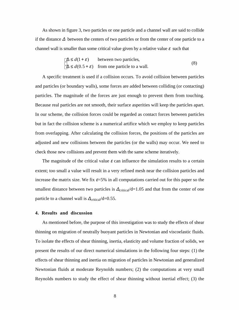
FIGURE 3. Detection of collision. The critical distance ∆ between two particles or from one particle to a
wall satisfies equation (8).
8
As shown in figure 3, two particles or one particle and a channel wall are said to collide
if the distance ∆ between the centers of two particles or from the center of one particle to a
channel wall is smaller than some critical value given by a relative value ε such that
∆ ≤ d(1 + ε) between two particles,
∆ ≤ d(0.5 + ε) from one particle to a wall.
(8)
A specific treatment is used if a collision occurs. To avoid collision between particles
and particles (or boundary walls), some forces are added between colliding (or contacting)
particles. The magnitude of the forces are just enough to prevent them from touching.
Because real particles are not smooth, their surface asperities will keep the particles apart.
In our scheme, the collision forces could be regarded as contact forces between particles
but in fact the collision scheme is a numerical artifice which we employ to keep particles
from overlapping. After calculating the collision forces, the positions of the particles are
adjusted and new collisions between the particles (or the walls) may occur. We need to
check those new collisions and prevent them with the same scheme iteratively.
The magnitude of the critical value ε can influence the simulation results to a certain
extent; too small a value will result in a very refined mesh near the collision particles and
increase the matrix size. We fix ε=5% in all computations carried out for this paper so the
smallest distance between two particles is ∆critical/d=1.05 and that from the center of one
particle to a channel wall is ∆critical/d=0.55.
4. Results and discussion
As mentioned before, the purpose of this investigation was to study the effects of shear
thinning on migration of neutrally buoyant particles in Newtonian and viscoelastic fluids.
To isolate the effects of shear thinning, inertia, elasticity and volume fraction of solids, we
present the results of our direct numerical simulations in the following four steps: (1) the
effects of shear thinning and inertia on migration of particles in Newtonian and generalized
Newtonian fluids at moderate Reynolds numbers; (2) the computations at very small
Reynolds numbers to study the effect of shear thinning without inertial effect; (3) the

9
effects of shear thinning and elasticity on migration of particles in viscoelastic fluids at
small Reynolds number; (4) the effect of volume fraction of solids. The numerical results
were compared to a series of experimental studies.
0
5
10
15
20
25
30
0 2 4 6 8 10
Fluid (n=1.0)
Particles
Vel
ocit
y P
rofi
le U
(cm
/s)
Re=12.5De=0.0
Y (cm)
(a)
d=1 cm
(b)
y
x
FIGURE 4. Migration of 56 neutrally buoyant particles in a pressure driven flow of a Newtonian fluid
without shear thinning (n=1.0). Re=12.5. (a) Velocity profile of the fluid without particles and the
velocities of the particles; (b) particle positions in the channel at time t=39.75 s. This flow lubricates in
that there are no particles at the center and the particles tend to accumulate a distance 0.6 from the center of
the channel, close to the radius in a pipe where spherical particles were observed to accumulate by Segré-
Segré and Silberberg [2].

10
4.1. Migration in Newtonian and generalized Newtonian
fluids at moderate Reynolds number
First consider the migration of particles in Newtonian and generalized Newtonian fluids
with a moderate Reynolds number. The viscosity of the fluid is fixed η = 1.0 g⋅ cm-1⋅ s−1
and the pressure gradient is dp dx = 2.0 g⋅ cm-2 ⋅ s−1 .
Figure 4 shows the migration of particles in a Newtonian fluid without shear thinning.
The maximum fluid velocity is Umax = 25 cm⋅ s−1 at the centerline, which gives the
Reynolds number Re=12.5. The maximum particle velocity is Up = 15 cm⋅ s−1 near the
centerline and the related maximum slip velocity of the particles Uslip = 10 cm⋅ s−1, as
shown in table 1. The difference between the velocity profile in solid curve (without
particles) and symbols (with particles) in figure 4(a) is the "slip velocity". The slip velocity
defined in this way is frequently used as a model parameter, however, we do not mean here
to assign a dynamic significance to this concept. The presence of particles increases the
flow resistance at a given pressure gradient and reduces the volume flux of liquid, the
extent of this reduction can be evaluated using the slip velocity.
n Re Umax Up Uslip
1.0 12.5 25 15 10
0.7 23.7 47.4 24.4 23
0.5 42.3 84.5 29.6 54
0.4 56.0 111.9 30.5 81.4
TABLE 1. The maximum slip velocity of the neutrally buoyant particles in a pressure driven flow of
generalized Newtonian fluids. Uslip increases rapidly when the effects of shear thinning become larger (n
smaller). All velocities are expressed in cm·s-1.
As illustrated in figure 4(a), there is a small zone in the center of the channel
(4.550≤Y≤5.431) where there are no particles. The size of this "particle-free zone" is
∆zone=0.881 for n=1.0. Also there are no particles near the channel walls (Y≤1.035 and
Y≥8.997). The average gap between the center of the particles and the channel wall is
∆gap=1.019. The particles are located between 1.035≤Y≤4.550 and 5.431≤Y≤8.997, as

11
shown in table 2. Lubrication forces move the particles away from the channel walls while
the curvature of the velocity profile moves the particles away from the centerline of the
channel where the shear rate is zero. This case has been computed for 400 time steps until
time t=39.75 second. The particle positions at this time is shown in figure 4(b).
0
10
20
30
40
50
0 2 4 6 8 10
Fluid (n=0.7)
Particles
Vel
ocit
y P
rofi
le U
(cm
/s)
Re=23.7De=0.0
Y (cm)
(a)
d=1 cm
(b)
y
x
FIGURE 5. Migration of 56 neutrally buoyant particles in a pressure driven flow of a generalized
Newtonian fluid (n=0.7). Re=23.7. (a) Velocity profile of the fluid without particles and the velocities of
the particles; (b) particle positions in the channel at time t=42.46 s. There is a small "particle-free zone" at
the center of the channel.

12
Now consider a generalized Newtonian fluid. With the Carreau-Bird viscosity law, the
effects of shear thinning can be imposed by decreasing the power index in equation (5). To
isolate the effects of shear thinning, we keep all the other parameters the same as in the
Newtonian fluid (n=1.0). The parameters used in this case are: η0 = 1.0 g⋅ cm−1⋅ s−1,
η∞ η0
= 0.1, and λ3= 1.0 s .
0
20
40
60
80
100
0 2 4 6 8 10
Fluid (n=0.5)
Particles
Vel
ocit
y P
rofi
le U
(cm
/s)
Re=42.3De=0.0
Y (cm)
(a)
d=1 cm
(b)
y
x
FIGURE 6. Migration of 56 neutrally buoyant particles in a pressure driven flow of a generalized
Newtonian fluid (n=0.5). Re=42.3. (a) Velocity profile of the fluid without particles and the velocities of
the particles; (b) particle positions in the channel at time t=31.78 s. The particles migrate toward the wall.

13
The velocity profile with shear thinning is much different from that of n=1.0. From
table 1 for n=0.7, the maximum fluid velocity at the centerline is Umax = 47.4 cm⋅ s−1 and
the Reynolds number is Re=23.7. The maximum particle velocity is Up = 24.4 cm⋅ s−1 .
Now the maximum slip velocity Uslip = 23 cm⋅ s−1 is much larger than that in a Newtonian
fluid without shear thinning (n=1.0). The stresses induced by shear thinning move the
particles away from the centerline of the channel, as shown in figure 5(a) where the
"particle-free zone" near the centerline (3.981≤Y≤6.006) becomes much larger
(∆zone=2.025). The few particles in the center would migrate away in a longer simulation.
The particles migrate to the channel wall, the gap becomes much smaller (∆gap=0.7468).
From table 2, the particles finally located between 0.7986≤Y≤3.981 and 6.006≤Y≤9.305.
The computations for this case has been carried out to t=42.46 second; the particle
positions at this time is shown in figure 5(b).
n Re Ymin Y1 Y2 Ymax ∆zone ∆gap
1.0 12.5 1.0350 4.550 5.431 8.997 0.881 1.0190
0.7 23.7 0.7986 3.981 6.006 9.305 2.025 0.7468
0.5 42.3 0.6428 3.796 5.918 9.264 2.122 0.6894
0.4 56.0 0.6517 3.805 6.211 9.326 2.406 0.6629
TABLE 2. The particle-free zone ∆zone and the average gap ∆gap between the center of the particles and the
channel walls in the migration of 56 neutrally buoyant particles in a pressure driven flow of generalized
Newtonian fluids. When the effects of shear thinning increase, the particle-free zone (Y1, Y2) becomes
larger and the particles move closer to the channel walls. The Y's and ∆'s are in centimeters.
To increase the effect of shear thinning, we reduce the power index to n=0.5; the
maximum fluid velocity is Umax = 84.5 cm⋅ s−1 at the centerline and Re=42.3. The
maximum particle velocity is Up = 29.6 cm⋅ s−1. Now the maximum slip velocity of the
particles is as high as Uslip = 54 cm⋅ s−1. As shown in figure 6(a), the strong stresses
induced by shear thinning move the particles away from the centerline of the channel, the
"particle-free zone" near the centerline (∆zone=2.122) is a little larger than that for n=0.7.
There is still one particle in this zone at the time shown in figure 6 and this particle would

14
migrate away from the zone. The particles also migrate much closer to the channel wall
(∆gap=0.6894) and locate between 0.6428≤Y≤3.796 and 5.918≤Y≤9.264. The particle
positions at time t=31.78 second is shown in figure 6(b).
0
20
40
60
80
100
120
0 2 4 6 8 10
Fluid (n=0.4)
Particles
Vel
ocit
y P
rofi
le U
(cm
/s)
Re=56De=0.0
Y (cm)
(a)
d=1 cm
(b)
y
x
FIGURE 7. Migration of 56 neutrally buoyant particles in a pressure driven flow of a generalized
Newtonian fluid (n=0.4). Re=56. (a) Velocity profile of the fluid without particles and the velocities of the
particles; (b) particle positions in the channel at time t=25.66 s.
We increase shear thinning by reducing the power index to n=0.4; this is the smallest
index we can run with our Particle-Mover package. The Reynolds number increases
rapidly to Re=56 with only modest increase of the maximum particle velocity to

15
Up = 30.5 cm⋅ s−1. From figure 7(a) and table 1, we can see that the maximum slip velocity
of the particles for n=0.4 is Uslip = 81.4 cm⋅ s−1, which is the largest slip velocity for all
cases presented in this section. All the particles migrate away from the "particle-free zone"
(3.805≤Y≤6.211) in the centerline and close to the channel wall. The size of the particle-
free zone (∆zone=2.406) reaches its maximum while the gap between the particles and the
channel walls (∆gap=0.6629) has the smallest value. The particles locate between
0.6517≤Y≤3.805 and 6.211≤Y≤9.326 at time t=27.41, as shown in figure 7(b).
n Re Ymin Y1 Y2 Ymax ∆zone ∆gap
1.0 12.500 1.0350 4.550 5.431 8.997 0.881 1.0190
1.0 2.500 0.5942 —— —— 9.450 —— 0.5721
1.0 0.156 0.5516 —— —— 9.450 —— 0.5508
1.0 0.000 0.6134 —— —— 9.420 —— 0.5967
0.5 42.300 0.6428 3.796 5.918 9.264 2.122 0.6894
0.5 4.940 0.8231 4.443 5.526 9.266 1.083 0.7786
0.5 0.157 0.5499 —— —— 9.450 —— 0.5500
0.5 0.000 0.5500 —— —— 9.450 —— 0.5500
TABLE 3. The particle-free zone ∆zone and the average gap ∆gap between the particles and the channel walls.
in the migration of 56 neutrally buoyant particles in a pressure driven flow of a generalized Newtonian
fluid. When the effects of shear thinning increase, the particle-free zone (Y1, Y2) becomes larger and the
particles move closer to the channel walls. All lengths are in centimeters.
We can conclude from figures 4-7 and table 2 that in a pressure driven flow of neutrally
buoyant particles the effects of shear thinning and the curvature of the velocity profile
induce strong shear stresses and large slip velocities, thereby causing the particles to
migrate away from the centerline of the channel and move toward the channel walls.
The flow behavior is consistent with the experimental results by Segré & Silberberg
[2], Tehrani [6] and the calculations by Asmolov [11]. Tehrani observed the migration of
proppant particles in either uncrosslinked or lower crosslinked fluids at low flow rates and
found that the particles migrate toward the pipe walls. In his experiment, the fluids have
very low normal stresses at low flow rates, therefore, can be treated as Newtonian or

16
generalized Newtonian fluids. Asmolov [11] declaimed that the inertial lift on a spherical
particle strongly depends on the curvature of the velocity profile, the distance from the wall
and the slip velocity.
0
1
2
3
4
5
6
7
0 2 4 6 8 10
Fluid (n=1.0)
Particles
Vel
ocit
y P
rofi
le U
(cm
/s)
Re=2.5De=0.0
Y (cm)
(a)
d=1 cm
(b)
y
x
FIGURE 8. Migration of 56 neutrally buoyant particles in a pressure driven flow of a Newtonian fluid
without shear thinning (n=1.0). Re=2.5. (a) Velocity profile of the fluid without particles and the velocities
of the particles; (b) particle positions in the channel at time t=248.1 s. There is no "particle-free zone" in
the center.

17
4.2. Migration in Newtonian and generalized Newtonian
fluids at smaller Reynolds number
To focus our attention on the effects of shear thinning and reduce the effects of inertia,
we compute similar cases with smaller Reynolds numbers.
0
2
4
6
8
10
0 2 4 6 8 10
Fluid (n=0.5)
Particles
Vel
ocit
y P
rofi
le U
(cm
/s)
Re=4.94De=0.0
Y (cm)
(a)
d=1 cm
(b)
y
x
FIGURE 9. Migration of 56 neutrally buoyant particles in a pressure driven flow of a generalized
Newtonian fluid (n=0.5). Re=4.94. (a) Velocity profile of the fluid without particles and the velocities of
the particles; (b) particle positions in the channel at time t=91.87 s. A small "particle-free zone" develops
at the center.

18
0
0 . 1
0 . 2
0 . 3
0 . 4
0 . 5
0 . 6
0 . 7
0 2 4 6 8 10
Fluid (n=1.0)
Particles
Vel
ocit
y P
rofi
le U
(cm
/s)
Re=0.156De=0.0
Y (cm)
(a)
d=1 cm
(b)
y
x
FIGURE 10. Migration of 56 neutrally buoyant particles in a pressure driven flow of a Newtonian fluid
without shear thinning (n=1.0). Re=0.156. (a) Velocity profile of the fluid without particles and the
velocities of the particles; (b) particle positions in the channel at time t=2728.8 s. There is no "particle-free
zone" at the center. Segré-Silberberg effects have not yet taken hold because inertial forces are weak and the
simulation time is not very long.
In figures 8 and 9, the pressure gradient is reduced to dp dx = 0.5 g⋅ cm-2 ⋅ s−1 and all
the other parameters are the same as in section 4.1. Without shear thinning (n=1.0), the
Reynolds number is Re=2.5 and the slip velocity of the particles is Uslip = 2.53 cm⋅ s−1.
The particles migrate toward the centerline, there is no "particle-free zone" in the channel.

19
The particles also migrate toward the channel walls, the gap from the particles to the walls
(∆gap=0.5721) is very small, as shown in table 3. The effect of inertia is too small to
migrate the particles away from the center and the channel walls.
0
0 . 1
0 . 2
0 . 3
0 . 4
0 . 5
0 . 6
0 . 7
0 2 4 6 8 10
Fluid (n=0.5)
Particles
Vel
ocit
y P
rofi
le U
(cm
/s)
Re=0.157De=0.0
Y (cm)
(a)
d=1 cm
(b)
y
x
FIGURE 11. Migration of 56 neutrally buoyant particles in a pressure driven flow of a generalized
Newtonian fluid (n=0.5). Re=0.157. (a) Velocity profile of the fluid without particles and the velocities of
the particles; (b) particle positions in the channel at time t=3892.0 s.
When the shear thinning index n=0.5, the Reynolds number is Re=4.94 and the slip
velocity is Uslip = 4.19 cm⋅ s−1. A "particle-free zone" develops at the centerline

20
(∆zone=1.083, see figure 9), although it is smaller than the one with n=0.5 and Re=42.3
(∆zone=2.122; there is also a small gap between the particles and the channel walls
(∆gap=0.7786). The stresses induced by shear thinning are large enough to move the
particles away from the centerline and from the channel walls.
0
5
10
15
20
25
30
0 2 4 6 8 10
Fluid (n=1.0)
Particles
Vel
ocit
y P
rofi
le U
(cm
/s)
Re=0.0De=0.0
Y (cm)
(a)
d=1 cm
(b)
y
x
FIGURE 12. Migration of 56 neutrally buoyant particles in a pressure driven flow of a Newtonian fluid
without shear thinning (n=1.0) or inertia (Re=0.0). (a) Velocity profile of the fluid without particles and the
velocities of the particles; (b) particle positions in the channel at time t=43.27 s. The slip velocities at zero
Reynolds number are rather large.

21
Now we reduce the pressure gradient to dp dx = 0.1 g⋅ cm-2 ⋅ s−1 and change the fluid
viscosity to η0 = 2.0 g⋅ cm-1⋅ s−1 while all the other parameters are the same as in section
4.1. The results are shown in figures 10 and 11.
Without shear thinning (n=1.0), the Reynolds number is Re=0.156 and the maximum
slip velocity of the particles is Uslip = 0.255 cm⋅ s−1. For n=0.5, the Reynolds number is
Re=0.157 and the maximum slip velocity of the particles is Uslip = 0.269 cm⋅ s−1. Figures
10 and 11 show that there is no "particle-free zone" in the center for both cases. The effect
of inertia is not strong enough to move the particles away from the centerline, even with the
help of the stresses induced by the shear thinning.
The flow pattern without shear thinning in figure 11 is only slightly different from that
with shear thinning in figure 10. Shear thinning has very small effect on particle migration
when the inertia or shear rate is small. To verify this, we turn off the effect of inertia
completely by removing the term u ⋅ ∇ u in equation (2) so that the Reynolds number is set
to zero. All the other parameters are the same as in section 4.1. The results are shown in
figures 12 and 13. The flow patterns shown in figures 10 and 12 for migrations in
Newtonian fluids are quite similar to the experimental phenomenon observed by Jefri &
Zahed [5] for suspensions in a pure corn syrup, which is a Newtonian fluid. In their study
on migration of particles in plane-Poiseuille flow under creeping flow conditions, the
neutrally buoyant particles are uniformly distributed in both the transverse and axial
directions. Their particle Reynolds number is in the order of 10-3 and their volume fraction
of solids is very low ( Cp = 0.02).
The difference in the flow patterns shown in figures 12 and 13 are relatively minor,
whereas the difference in the flow patterns shown in figures 4 and 6 are considerable. In
the former cases, shear thinning apparently has no effect on the particle's migration when
inertia is turned off, although the difference between the slip velocities is still quite large.
For flows with small inertia there is no "particle-free zone" at the centerline even if the fluid
is shear thinning. Table 3 shows that there is no gap between the particles and the channel

22
(∆gap=0.55) for n=0.5 while there is a very small gap (∆gap=0.5967) for n=1.0; this small
gap could be transient.
0
20
40
60
80
100
0 2 4 6 8 10
Fluid (n=0.5)
Particles
Vel
ocit
y P
rofi
le U
(cm
/s)
Re=0.0De=0.0
Y (cm)
(a)
d=1 cm
(b)
y
x
FIGURE 13. Migration of 56 neutrally buoyant particles in a pressure driven flow of a generalized
Newtonian fluid (n=0.5) with no inertia (Re=0.0). (a) Velocity profile of the fluid without particles and the
velocities of the particles; (b) particle positions in the channel at time t=25.42 s.
We can conclude from figures 8-13 and table 3 that the dependence of the flow
behavior on shear thinning is weak but does not vanish completely when the inertia effects
are small. The weak effect of shear thinning comes from viscous stresses and is smaller
when the flow is slow; in slow flow, layers of fluid without particles do not appear.

23
4.3. Migration in an Oldroyd-B fluid
Now consider the migration of particles in an Oldroyd-B fluid. We focus our attention
on the combined effects of viscoelastic normal stresses and shear thinning after reducing
the effect of inertia. First we look at the effects of viscoelasticity without shear thinning.
We set parameters so that the elasticity number is above its critical value and the viscoelastic
Mach number M <1; Huang, Hu and Joseph [12] have shown that in this condition the
effect of elasticity is much stronger than the effect of inertia. The aforementioned condition
is represented by the following particular choices of parameters: the constant viscosity of
fluid η = 2.0 g⋅ cm−1⋅ s−1, the relaxation time λ1= 2.0 s and the ratio of relaxation and
retardation time λ2
λ1= 1 8. The pressure gradient used here is the same as in figures 10
and 11: dp dx = 0.1 g⋅ cm−2 ⋅ s−2 . Then the elasticity number is fixed at E=16 throughout
this section.
Without shear thinning, the Reynolds number for the flow without particles is
Re=0.156, the Deborah number is De=2.50 and the Mach number M=0.625. From figure
14(a) we notice that the flow pattern is very different from that in the Newtonian or
generalized Newtonian fluids discussed in sections 4.1 and 4.2. There does not exist a
"particle-free zone" in the centerline. Actually the particles move toward the centerline of
the channel by forces arising from viscoelastic normal stresses. The distribution of the
particles at time t=1613.9 second is shown in figure 14(b). Comparing figure 14
(De=2.50) and figure 10 (De=0.0), we find that more particles migrate to the centerline for
De=2.50 than for De=0.0 when all other parameters are the same.
We next consider the combined effects of shear thinning and viscoelasticity. Shear
thinning is inserted in the Oldroyd-B equation (3) using the Carreau-Bird expression (5) for
viscosity, with the following parameters fixed: η0 = 2.0 g⋅ cm−1⋅ s−1, η∞ η0
= 0.1 and
λ3
λ1= 1.0 . All the other parameters are the same as those without shear thinning.

24
0
0 . 1
0 . 2
0 . 3
0 . 4
0 . 5
0 . 6
0 . 7
0 2 4 6 8 10
Fluid (n=1.0)
Particles
Vel
ocit
y P
rofi
le U
(cm
/s)
Re=0.156De=2.50
Y (cm)
(a)
d=1 cm
(b)
y
x
FIGURE 14. Migration of 56 neutrally buoyant particles in a pressure driven flow of an Oldroyd-B fluid
without shear thinning (n=1.0). Re=0.156, De=2.50, E=16 and M=0.625. (a) Velocity profile of the fluid
without particles and the velocities of the particles; (b) particle positions in the channel at time t=1613.9 s.
Normal stresses associated with viscoelasticity tend to concentrate particles at the channel center.
The combination of shear thinning and viscoelasticity produces a new flow pattern;
instead of creating a "particle-free zone" in the centerline as for a generalized Newtonian
fluid, the elastic normal stresses move particles toward the centerline while the stresses
induced by shear thinning move particles toward the channel walls, thereby creating a
"core-annular flow pattern". There are two "annular particle-free zones" and a "core

25
particle-laden zone" in the center. Most of the particles are located in the core zone around
the centerline, while others make long chains and move along the channel walls. We carry
out systematic computations as shown in figures 15-17 where the power index are n=0.7,
0.5 and n=0.4, respectively.
0
0 . 1
0 . 2
0 . 3
0 . 4
0 . 5
0 . 6
0 . 7
0 2 4 6 8 10
Fluid (n=0.7)
Particles
Vel
ocit
y P
rofi
le U
(cm
/s)
Re=0.159De=2.54
Y (cm)
(a)
d=1 cm
(b)
y
x
FIGURE 15. Migration of 56 neutrally buoyant particles in a pressure driven flow of an Oldroyd-B fluid
with shear thinning (n=0.7). Re=0.159, De=2.54, E=16 and M=0.635. (a) Velocity profile of the fluid
without particles and the velocities of the particles; (b) particle positions in the channel at time t=970.3.
There are two "annular particle-free zones" and a "core particle-laden zone".

26
0
0 . 1
0 . 2
0 . 3
0 . 4
0 . 5
0 . 6
0 . 7
0 2 4 6 8 10
Fluid (n=0.5)Particles
Vel
ocit
y P
rofi
le U
(cm
/s)
Re=0.161De=2.57
Y (cm)
(a)
d=1 cm
(b)
y
x
FIGURE 16. Migration of 56 neutrally buoyant particles in a pressure driven flow of an Oldroyd-B fluid
with shear thinning (n=0.5). Re=0.161, De=2.57, E=16 and M=0.6427. (a) Velocity profile of the fluid
without particles and the velocities of the particles; (b) particle positions in the channel at time t=1558.0.
Table 4 shows that there is no annular particle-free zone but large core particle-laden
zone (∆core=8.267) when shear thinning is suppressed; the particles move everywhere but
are more concentrated in the core (see figure 14) than in the Newtonian fluid shown in
figure 10. The stresses induced by shear thinning when n=0.7 move the particles to the
centerline, create two annular particle-free zones (∆annular=1.192), and reduce the size of
the particle-laden zone in the center (∆core=6.303). When the shear thinning is stronger,

27
this phenomenon is enhanced. For n=0.5, the sizes of the annular zone and core zone are
∆annular=1.231 and ∆core=6.286; for n=0.4, the sizes of the annular zone and core zone are
∆annular=1.401 and ∆core=5.651.
0
0 . 1
0 . 2
0 . 3
0 . 4
0 . 5
0 . 6
0 . 7
0 2 4 6 8 10
Fluid (n=0.4)Particles
Vel
ocit
y P
rofi
le U
(cm
/s)
Re=0.162De=2.59
Y (cm)
(a)
d=1 cm
(b)
y
x
FIGURE 17. Migration of 56 neutrally buoyant particles in a pressure driven flow of an Oldroyd-B fluid
with shear thinning (n=0.4). Re=0.162, De=2.59, E=16 and M=0.6466. (a) Velocity profile of the fluid
without particles and the velocities of the particles; (b) particle positions in the channel at time t=1303.0.
The slip velocity does not depend strongly on the power law index, but the flows are
different since inertial effects are small in these cases (Re≈0.16); the cause of the
differences in the migration of particles is to be found in the combined effects of shear

28
thinning and elasticity. The elasticity drives the particles toward the center while shear
thinning moves the particles toward the channel walls.
n Y1 Y2 Y3 Y4 ∆annular ∆core
1.0 0.616 —— —— 8.883 —— 8.267
0.7 0.644 1.912 8.215 9.330 1.192 6.303
0.5 0.614 1.784 8.070 9.362 1.231 6.286
0.4 0.760 2.242 7.893 9.212 1.401 5.651
TABLE 4. The average size of the annular particle-free zone and the size of the core zone of high particle
concentration in the migration of 56 neutrally buoyant particles in a pressure driven flow of a viscoelastic
fluid with shear thinning. When the effects of shear thinning increase, the size of the annular particle-free
zones (Y1, Y2) and (Y3, Y4) increase while the core particle-laden zone (Y2, Y3) decreases. All the
lengths are in centimeters.
In the experimental study by Tehrani [6], he observed the non-neutrally buoyant
particles migrate toward the pipe axis in uncrosslinked and lower crosslinked fluids when
the flow rate becomes high; while the particles migrate toward the pipe walls in the same
fluids at low flow rate. The change of flow behavior is assumed to be the effects of
nonzero normal stresses and larger shear rate gradients. The forces, arising from both the
elastic normal stresses and the shear rate gradients, drive the particles toward the region of
lower shear rate at the centerline of the channel. The effects of elasticity become dominant
when the flow rate becomes high, so that the fluids can be treated as viscoelastic fluids with
shear thinning. The volume fraction of solids is Cp = 0.12.
Tehrani's experimental results are similar to our numerical computations in general but
he did not mention if there are any particles near the pipe walls. This is possibly due to his
experimental setup and image processing. Tehrani identified the inner wall of the pipe from
images where a brighter background lighting was used. The presence of the particles were
recognized by scanning the intensity profiles from left to right. If there were peaks with
intensities less than 60%-70% of the average value, then these values were discounted. In
that way, the low concentration of particles near the walls may be either out of the inner

29
walls or discounted, so he observed only the "core particle-laden zone" but no "annular
particle-free zone".
In high crosslinked fluids, Tehrani found that the particles migrate toward the pipe
center even if the flow rates are low. When the fluids are higher crosslinked, particles
migrate at the beginning and soon form a roughly uniform distribution near the central
region. Tehrani believed that shearing at this central plug becomes very small because of
the presence of the high concentration of the solids, resulting in a high viscosity. Without
high shear rate gradients, the particles no longer migrate, even with the high normal
stresses. The flow conditions in Tehrani's experiments were chosen to be similar to
hydraulic fracturing operations, having the particle Reynolds number of order 10-4~1 and
Deborah number in the order of 50.
On the other hand, Jefri & Zahed [5] found that neutrally buoyant particles tend to
migrate toward the centerline, creating a narrow core in a non-shear thinning elastic
medium, the same phenomenon as in our computation results. However, Jefri & Zahed [5]
also found that the particles migrate to an annular region between the walls and the
centerline of the channel in a shear thinning elastic fluid. They did not comment on this
flow behavior. The flow rate in their experiments is very slow so that the effect of inertia is
negligible ( Re ∝ 10−4 ), their volume fraction of solids is very low ( Cp = 0.02) but the
effect of elasticity is extremely high ( De ∝ 102). The flow behavior observed by Jefri &
Zahed [5] is different than that observed by Tehrani [6], but the source of this difference is
not shown. Our simulations do not rise to the experiments because they do not converge
for De>5.
4.4. Effect of volume fraction of solids
To study the effect of volume fraction of solids on flow behavior, we double the
number of particles from 56 to 112 in the channel and consider Newtonian, generalized
Newtonian and shear thinning Oldroyd-B fluids. The volume fraction of 112 particles in
our flow domain is Cp = 0.42. Figures 18 and 19 show that "particle-free zones" at the

30
channel center in Newtonian and generalized Newtonian fluids are suppressed in
concentrated dispersions. The channel center is basically shear free; the migration away
from the center in more dilute cases is caused by the curvature of the velocity profile.
0
5
10
15
20
25
30
0 2 4 6 8 10
Fluid (n=1.0)
Particles
Vel
ocit
y P
rofi
le U
(cm
/s)
Re=42.3De=0.0
Y (cm)
(a)
d=1 cm
(b)
y
x
FIGURE 18. Migration of 112 neutrally buoyant particles in a pressure driven flow of a Newtonian fluid
(n=1.0). Re=12.5. (a) Velocity profile of the fluid without particles and the velocities of the particles; (b)
particle positions in the channel at time t=71.66 s.
The main effect of the increased loading of solids is to suppress the migration of
particles away from the center where the effects of shear thinning are the weakest because
the shear rates are small (cf. figures 4 and 18 for Re=12.5 and n=10, and figures 6 and 19

31
for Re=42.3 and n=0.5). This migration away from the center is generally believed to be an
effect of the curvature of the velocity profile (see Asmolov [11]), an effect which may be
diminished by the presence of many particles. With high volume fraction of solids, the
effects of slip velocity have been greatly reduced. As can be seen in table 5, the slip
velocities are even higher with high Cp because the particles move much slower. Instead of
migrating toward the channel walls, the particles now stay near the center region with
almost no migration, as shown in figures 18 and 19. On the other hand, the effects of shear
thinning at the walls are not so strongly changed by the increase in the volume fraction of
solids.
Cp n Re Umax Up Uslip
0.21 1.0 12.5 25 15 10
0.42 1.0 12.5 25 7.8 17
0.21 0.5 42.3 84.5 29.6 54
0.42 0.5 42.3 84.5 23.8 61
TABLE 5. The maximum slip velocity of the neutrally buoyant particles. Uslip increases when the volume
fraction of solids Cp becomes larger.
In an Oldroyd-B fluid (Re=0.161, De=2.57, E=16, M=0.6427 and n=0.5), as can be
seen in figure 20, the flow pattern shows no significant difference from the more dilute
case in figure 16 although the annular "particle-free zone" is smaller due to the high volume
fraction. The effect of elasticity moves the particles toward the centerline, while shear
thinning moves particles toward the channel walls, creating a small annular "particle-free
zone". The high volume fraction decreases the shear rate, thus decreasing the effects of
both shear thinning and elastic normal stresses. It is particularly noteworthy that the
combined effect of shear thinning and elasticity leads to chains of particles on the wall for
both high and low solids loadings.

32
0
20
40
60
80
100
0 2 4 6 8 10
Fluid (n=0.5)
Particles
Vel
ocit
y P
rofi
le U
(cm
/s)
Re=42.3De=0.0
Y (cm)
(a)
d=1 cm
(b)
y
x
FIGURE 19. Migration of 112 neutrally buoyant particles in a pressure driven flow of a generalized
Newtonian fluid (n=0.5). Re=42.3. (a) Velocity profile of the fluid without particles and the velocities of
the particles; (b) particle positions in the channel at time t=42.67 s.
Tehrani [6] also studied the effect of solids concentration. He found that the rate of
migration toward pipe axis in high degree of crosslinking fluids decreases rapidly once the
centerline concentration reaches around 0.3. As the concentration near the axis increases,
the shear rate at the region near the centerline decreases, resulting in the increasing of the
viscosity. When viscosity increases, the driving force for migration toward the centerline,

33
arising from the local normal stresses and the shear rate gradient, decreases; while the
resisting force arising from viscosity increases.
0
0 . 1
0 . 2
0 . 3
0 . 4
0 . 5
0 . 6
0 . 7
0 2 4 6 8 10
Fluid (n=0.5)Particles
Vel
ocit
y P
rofi
le U
(cm
/s)
Re=0.161De=2.57
Y (cm)
(a)
d=1 cm
(b)
y
x
FIGURE 20. Migration of 112 neutrally buoyant particles in a pressure driven flow of an Oldroyd-B fluid
with shear thinning (n=0.5). Re=0.161, De=2.57, E=16, M=0.6427. (a) Velocity profile of the fluid
without particles and the velocities of the particles; (b) particle positions in the channel at time t=1594 s.
5. Conclusions
The flow behavior of neutrally buoyant particles migrating in a pressure driven flow of
Newtonian and viscoelastic fluids, depends strongly on the volume fraction of solids, the

34
blockage ratio of the channel, the effects of inertia and elasticity, and the effects of shear
thinning.
Inertia always tends to move particles away from the channel walls and from the
centerline of the channel, while the elasticity causes them to migrate toward the centerline.
In general, shear thinning moves the particles away from the centerline but toward the
channel walls when the inertia or elasticity is strong enough.
In Newtonian or generalized Newtonian fluids at moderate Reynolds numbers, when
the effects of shear thinning become stronger, the particle-free zone along the centerline of
the channel becomes larger and the particles move closer to the channel walls, as long as
the effect of inertia is strong enough. If the effect of inertia is too weak, the dependence of
the flow behavior of the particles on the shear thinning is very weak.
The effects of shear thinning and the curvature of the velocity profile induce strong
shear stresses and large slip velocities, thus causing the particles to migrate away from the
centerline of the channel and move toward the channel walls.
In a viscoelastic fluid, the particles migrate toward the centerline of the channel even
without shear thinning. With shear thinning, most of the particles migrate toward a core
zone in the center of the channel, while others form long chains and move along the
channel walls. There exist two "annular particle-free zones" and a "core particle-laden
zone". The core zone becomes narrower as the effect of shear thinning is increased.
A high volume fraction of solids prevents the formation of the particle-free zone at the
centerline of the channel in Newtonian and generalized Newtonian fluids since the shear
rate becomes very small, although the slip velocity becomes larger. The volume fraction of
solids has a weaker effect on the migration in a viscoelastic fluid, it decreases the size of the
annular particle-free zone.
Acknowledgment: This work was partially supported by National Science Foundation
Grand Challenge grant KDI (NSF/CTS-98-73236), by the US Army, Mathematics, by the
DOE, Department of Basic Energy Sciences, by a grand from the Schlumberger
foundation, and from Stimlab Inc. and by the Minnesota Supercomputer Institute.

35
References
[1] J. F. Morris & J. F. Brady, Pressure-driven flow of a suspension: Buoyancy effects.
Int. J.. Multiphase Flow, 24 (1998) 105-130.
[2] G. Segré & A. Silberberg, Radial particle displacements in Poiseuille flow of
suspensions. Nature, 189 (1961) 209-210.
[3] A. Karnis & S. G. Mason, Particle motions in sheared suspensions. XIX. Viscoelastic
media. Thans. Soc. Rheol., 10 (1966) 571-592.
[4] F. Gauthier, H. L. Goldsmith & S. G. Mason, Particle motions in non-Newtonian
media II. Poiseuille flow. Thans. Soc. Rheol., 15 (1971) 297-330.
[5] M. A. Jefri & A. H. Zahed, Elastic and viscous effects on particle migration in plane-
Poiseuille flow. J. Rheol., 33 (1989) 691-708.
[6] M. A. Tehrani, An experimental study of particle migration in pipe flow of viscoelastic
fluids. J. Rheol., 40 (1996) 1057-1077.
[7] D. D. Joseph, Flow induced microstructure in Newtonian and viscoelastic fluids. In
Proc. of 5th World Congress of Chem. Engng., Particle Technology Track, San
Diego. July 14-18. AIChE , 6 (1996) 3-16.
[8] P. Y. Huang, J. Feng, H. H. Hu & D. D. Joseph, Direct simulation of the motion of
solid particles in Couette and Poiseuille flows of viscoelastic fluids. J. Fluid Mech. 343
(1997) 73-94.
[9] H. Binous & R. J. Phillips, Dynamic simulation of one and two particles sedimenting
in a viscoelastic suspension of FENE Dumbbells. J. Non-Newtonian Fluid Mech.,
(1998) (submitted).
[10] H. Binous & R. J. Phillips, The effect of sphere-wall interactions on particle motion
in a viscoelastic suspension of FENE Dumbbells. J. Non-Newtonian Fluid Mech.,
(1998) (submitted).
[11] E. S. Asmolov, The inertial lift on a spherical particle in a plane Poiseuille flow at
large channel Reynolds number. J. Fluids Engng., 381 (1999) 63-87.
[12] P. Y. Huang, H. H. Hu & D. D. Joseph, Direct simulation of the motion of elliptic
particles in Oldroyd-B fluids. J. Fluid Mech., 362 (1998) 297-325.
Updated on August 11, 1999


![A SHEAR-THINNING VISCOELASTIC FLUID MODEL FOR … · A SHEAR-THINNING VISCOELASTIC FLUID MODEL FOR ... study two other models in the same class ... polymers [12], ...](https://static.fdocuments.net/doc/165x107/5ad632c37f8b9a6d708dd709/a-shear-thinning-viscoelastic-fluid-model-for-shear-thinning-viscoelastic-fluid.jpg)


