
EFFECTS OF MUTUAL COUPLING AND DIRECTIVITY ON DOA ESTIMATION USING MUSIC LOPAMUDRA KUNDU & ZHE...
18
EFFECTS OF MUTUAL COUPLING AND DIRECTIVITY ON DOA ESTIMATION USING MUSIC LOPAMUDRA KUNDU & ZHE ZHANG
-
Upload
alexander-cain -
Category
Documents
-
view
231 -
download
1
Transcript of EFFECTS OF MUTUAL COUPLING AND DIRECTIVITY ON DOA ESTIMATION USING MUSIC LOPAMUDRA KUNDU & ZHE...

EFFECTS OF MUTUAL COUPLING AND DIRECTIVITY ON DOA ESTIMATION USING MUSIC
LOPAMUDRA KUNDU & ZHE ZHANG
Outline of the Presentation
What is DOA? MUSIC Parameter study:
Signal-to-noise ratio (SNR) Inter-element spacing Mutual coupling Directivity
Why DOA? Applications Scopes of future work

Direction of Arrival (DOA) Estimation
Estimation of direction finding signals in the form of electromagnetic/acoustic waves impinging on a sensor or antenna array.
High resolution DOA can resolve closely spaced frequencies.
Most popular technique is “Subspace method” Used for locating and tracking signal sources
in both military and civilian communications.
4
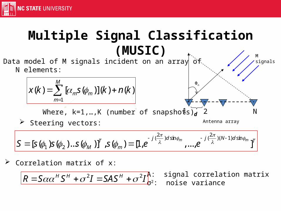
Multiple Signal Classification (MUSIC)
Steering vectors:
Data model of M signals incident on an array of N elements:
Where, k=1,…,K (number of snapshots)
1
( ) [ ( )]( ) ( )M
m mm
x k s k n k
2 2( ) sin ( )( 1) sin
1 2[ ( ) ( )... ( )] , ( ) [1, ,..., ]m mj d j N dT T
M mS s s s s e e
2 2H H HR S S I SAS I
Correlation matrix of x:
A: signal correlation matrixσ2: noise variance
1 2 NAntenna array
d
Msignals
Φn
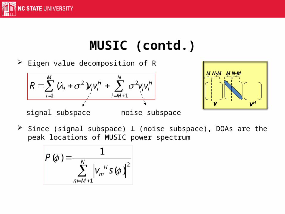
MUSIC (contd.) Eigen value decomposition of R
Since (signal subspace) (noise subspace), DOAs are the peak locations ⊥of MUSIC power spectrum
2
1
1( )
( )N
Hm
m M
Pv s
2 2
1 1
( )M N
H Hi i i i i
i i M
R v v v v
signal subspace noise subspace
M N-M M N-M
v vH
Parameters Affecting the Performance of MUSIC
Signal-to-Noise Ratio (SNR) Inter-element Spacing Mutual Coupling Antenna Directivity
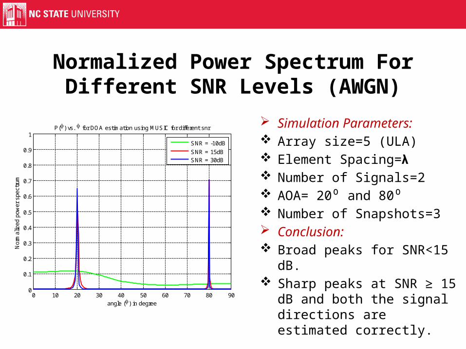
Normalized Power Spectrum For Different SNR Levels (AWGN)
Simulation Parameters: Array size=5 (ULA) Element Spacing=𝝺 Number of Signals=2 AOA= 20 and 80⁰ ⁰ Number of Snapshots=3 Conclusion: Broad peaks for SNR<15 dB. Sharp peaks at SNR ≥ 15 dB
and both the signal directions are estimated correctly.0 10 20 30 40 50 60 70 80 90
0
0.1
0.2
0.3
0.4
0.5
0.6
0.7
0.8
0.9
1
angle () in degree
Nor
mal
ized
pow
er s
pect
rum
P() vs. for DOA estimation using MUSIC for different snr
SNR = -10dB
SNR = 15dBSNR = 30dB

Normalized Power Spectrum For Various Inter-Element Spacing (No Coupling)
Simulation Parameters: Array size=5 (ULA) SNR level=30 dB (AWGN) Number of Signals=2 AOA=20 and 80⁰ ⁰ Number of Snapshots=3
Conclusion: Broad peaks for d<0.5 .𝝺 Sharp peaks at d≥0.5 and 𝝺
both the signal directions are estimated correctly.
0 10 20 30 40 50 60 70 80 900
0.1
0.2
0.3
0.4
0.5
0.6
0.7
0.8
0.9
angle () in degree
Nor
mal
ized
pow
er s
pect
rum
P() vs. for DOA estimation using MUSIC
d= 0.1
d= 0.5
d=

Normalized Power Spectrum in the Presence of Mutual Coupling
Simulation Parameters: Array size=5 (ULA) SNR level=50 dB Number of Signals=3 (LP) AOA=20 , 50 and 80⁰ ⁰ ⁰ Number of Snapshots=10
Conclusion: Broad peaks for d<0.5 .𝝺 Sharp peaks at d ≥ 0.5 and 𝝺
all the three signal directions are estimated correctly.
0 20 40 60 80 100 120 140 160 1800
0.1
0.2
0.3
0.4
0.5
0.6
0.7
0.8
0.9
1
angle () in degree
Nor
mal
ized
pow
er s
pect
rum
P() vs. for DOA estimation using MUSIC
d=1
d=0.5
d=0.1
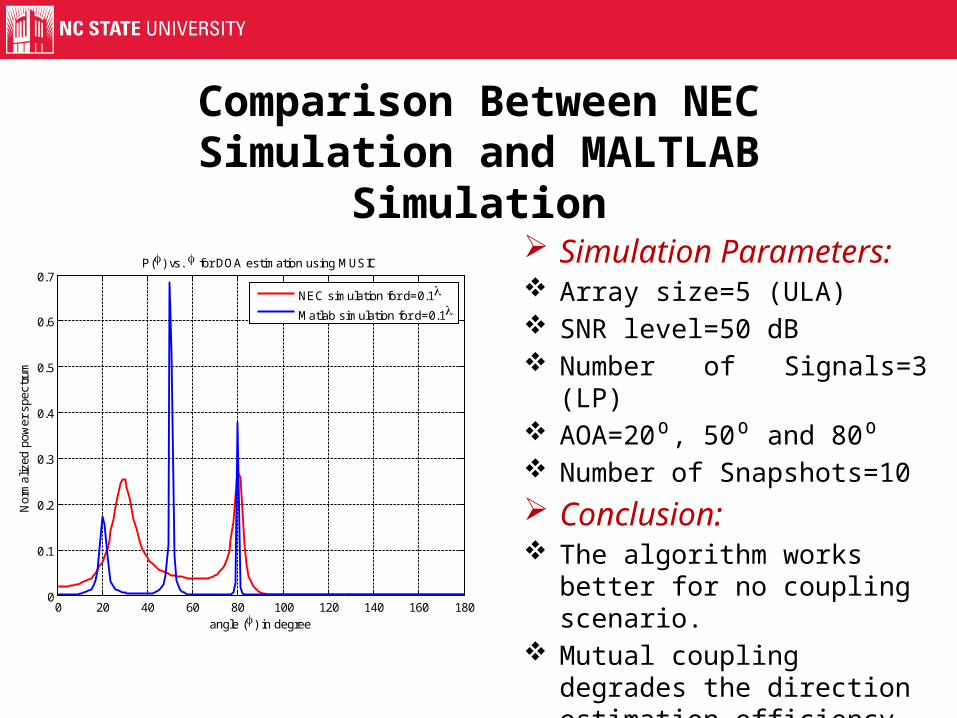
Comparison Between NEC Simulation and MALTLAB Simulation
Simulation Parameters: Array size=5 (ULA) SNR level=50 dB Number of Signals=3 (LP) AOA=20 , 50 and 80⁰ ⁰ ⁰ Number of Snapshots=10
Conclusion: The algorithm works better for
no coupling scenario. Mutual coupling degrades the
direction estimation efficiency considerably for same spacing.
0 20 40 60 80 100 120 140 160 1800
0.1
0.2
0.3
0.4
0.5
0.6
0.7
angle () in degree
Nor
mal
ized
pow
er s
pect
rum
P() vs. for DOA estimation using MUSIC
NEC simulation for d=0.1
Matlab simulation for d=0.1
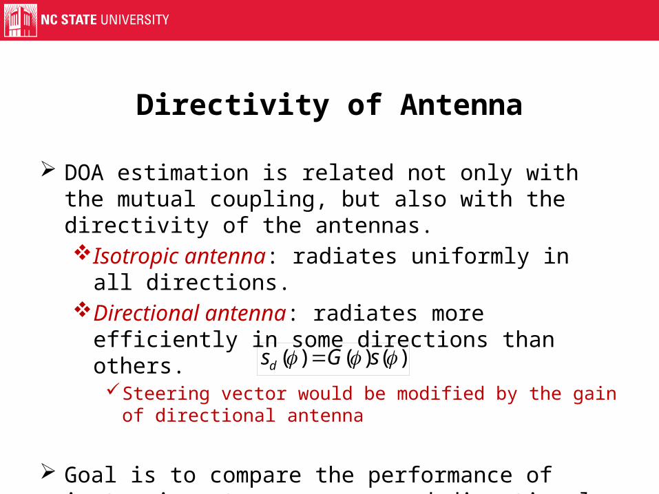
Directivity of Antenna
DOA estimation is related not only with the mutual coupling, but also with the directivity of the antennas.Isotropic antenna: radiates uniformly in all directions.Directional antenna: radiates more efficiently in some
directions than others.Steering vector would be modified by the gain of directional
antenna
Goal is to compare the performance of isotropic antenna arrays and directional antenna arrays in DOA estimation.
( ) ( ) ( )ds G s
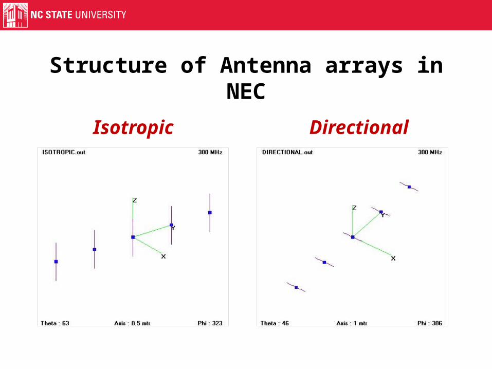
Structure of Antenna arrays in NEC
Isotropic Directional

Simulation Result for Isotropic Array
Analysis: Incident signals at 3 angles :
20⁰, 50⁰ and 80⁰ All 3 signals are detected
accurately. Isotropic array could detect
all the incident signals simultaneously.
0 10 20 30 40 50 60 70 80 900
0.1
0.2
0.3
0.4
0.5
0.6
0.7
Nor
mal
ized
Pow
er S
pect
rum
(P
())
angle () in degree

Simulation Result for Directional Array
0 10 20 30 40 50 60 70 80 900
0.1
0.2
0.3
0.4
0.5
0.6
0.7
0.8
0.9
1
Nor
mal
ized
Pow
er S
pect
rum
(P
())
angle () in degree
Analysis: Incident signals at 3 angles:
20⁰, 50⁰ and 90⁰. Only incoming signal at 90⁰
is detected. Directional array could only
detect the signals that fall within the range of its main beam position.
The gain of directional antenna may make the result more accurate.

Why DOA: Applications
DOA ESTIMATION
radar
SonarSeismic Exploration
Electronic Surveillance
Wireless Communication
Applications Involving Coupling and Directivity
Applications involving mutual coupling: MIMO system with closely spaced antennas.
Applications involving directivity: Indoor environment with intensive multipath effect and interferences.

Scopes of Future Work
Other types of arrays and antennas. Effects of other parameters like polarization, antenna
gain, delay and ground effects.

THANK YOU!


![Fling StepForward Directivity (BRBF)confnews.um.ac.ir/images/41/conferences/5ncce/1399.pdf · Fling StepForward Directivity Forward Directivity . [] g Forward Directivity Fling Step[]](https://static.fdocuments.net/doc/165x107/5ead3a2bf150643e9064f1eb/fling-stepforward-directivity-brbf-fling-stepforward-directivity-forward-directivity.jpg)


