Effects of monocortical and bicortical mini-implant ...
11
Effects of monocortical and bicortical mini-implant anchorage on bone-borne palatal expansion using finite element analysis Robert J. Lee, a Won Moon, b and Christine Hong b San Francisco and Los Angeles, Calif Introduction: Bone-borne palatal expansion relies on mini-implant stability for successful orthopedic expansion. The large magnitude of applied force experienced by mini-implants during bone-borne expansion may lead to high failure rates. Use of bicortical mini-implant anchorage rather than monocortical anchorage may improve mini-implant stability. The aims of this study were to analyze and compare the effects of bicortical and monocortical anchorages on stress distribution and displacement during bone-borne palatal expansion using finite element analysis. Methods: Two skull models were constructed to represent expansion before and after midpalatal suture opening. Three clinical situations with varying mini-implant insertion depths were studied in each skull model: monocortical, 1-mm bicortical, and 2.5-mm bicortical. Finite element analysis simulations were performed for each clinical situation in both skull models. Von Mises stress distribution and transverse displacement were evaluated for all models. Results: Peri-implant stress was greater in the monocortical anchorage model compared with both bicortical anchorage models. In addition, transverse displacement was greater and more parallel in the coronal plane for both bicortical models compared with the monocortical model. Minimal differences were observed between the 1-mm and the 2.5-mm bicortical models for both peri-implant stress and transverse displacement. Conclusions: Bicortical mini-implant anchorage results in improved mini-implant stability, decreased mini-implant deformation and fracture, more parallel expansion in the coronal plane, and increased expansion during bone-borne palatal expansion. However, the depth of bicortical mini-implant anchorage was not significant. (Am J Orthod Dentofacial Orthop 2017;151:887-97) T ransverse maxillary deficiency has been reported to affect 8% to 23% of adolescent patients and fewer than 10% of adult patients. 1-5 Rapid palatal expansion (RPE), which typically uses a tooth- borne appliance with a center jackscrew, is a well- established and reliable technique to correct this prob- lem for adolescent patients. 6-8 For adults, however, nonsurgical RPE with a tooth-borne appliance can result in dentoalveolar tipping that may cause unfavorable periodontal effects because of the interdigitated midpalatal suture and the decreased elasticity of bone in adults. 9-11 Therefore, in adults, skeletal orthopedic expansion is necessary to prevent these issues and to correct transverse maxillary deficiency. 12-14 Surgically assisted RPE is the conventional treatment of choice to correct transverse maxillary deficiency in adults. 9-11,15 However, surgically assisted RPE is an invasive process that can result in lateral rotation of the 2 maxillary halves with minimal horizontal translation. 9-11 In addition, surgically assisted RPE may be detrimental to the periodontium and has been shown to result in a large amount of relapse during the postretention period. 16,17 Recently, bone-borne palatal expanders have been reported in several case presentations to have the capa- bility to correct transverse maxillary deficiency in adults, making it a potential alternative to surgically assisted RPE. 18-21 Bone-borne expanders have also been shown to prevent the dentoalveolar tipping seen in adults when attempting to use traditional tooth-borne RPE a Division of Orthodontics, University of California at San Francisco, San Fran- cisco, Calif. b Section of Orthodontics, University of California at Los Angeles, Los Angeles, Calif. All authors have completed and submitted the ICMJE Form for Disclosure of Po- tential Conflicts of Interest, and none were reported. Address correspondence to: Christine Hong, 10833 Le Conte Ave, Los Angeles, CA 90095; e-mail, [email protected]. Submitted, April 2016; revised and accepted, October 2016. 0889-5406/$36.00 Ó 2017 by the American Association of Orthodontists. All rights reserved. http://dx.doi.org/10.1016/j.ajodo.2016.10.025 887 ORIGINAL ARTICLE
Transcript of Effects of monocortical and bicortical mini-implant ...

ORIGINAL ARTICLE
Effects of monocortical and bicorticalmini-implant anchorage on bone-bornepalatal expansion using finite elementanalysis
Robert J. Lee,a Won Moon,b and Christine Hongb
San Francisco and Los Angeles, Calif
aDiviscisco,bSectiCalif.All autentiaAddreCA 90Subm0889-� 201http:/
Introduction:Bone-borne palatal expansion relies onmini-implant stability for successful orthopedic expansion.The large magnitude of applied force experienced by mini-implants during bone-borne expansion may lead tohigh failure rates. Use of bicortical mini-implant anchorage rather than monocortical anchorage may improvemini-implant stability. The aims of this study were to analyze and compare the effects of bicortical andmonocortical anchorages on stress distribution and displacement during bone-borne palatal expansion usingfinite element analysis. Methods: Two skull models were constructed to represent expansion before and aftermidpalatal suture opening. Three clinical situations with varying mini-implant insertion depths were studied ineach skull model: monocortical, 1-mm bicortical, and 2.5-mm bicortical. Finite element analysis simulationswere performed for each clinical situation in both skull models. Von Mises stress distribution and transversedisplacement were evaluated for all models. Results: Peri-implant stress was greater in the monocorticalanchorage model compared with both bicortical anchorage models. In addition, transverse displacement wasgreater and more parallel in the coronal plane for both bicortical models compared with the monocortical model.Minimal differences were observed between the 1-mm and the 2.5-mm bicortical models for both peri-implantstress and transverse displacement. Conclusions: Bicortical mini-implant anchorage results in improvedmini-implant stability, decreased mini-implant deformation and fracture, more parallel expansion in thecoronal plane, and increased expansion during bone-borne palatal expansion. However, the depth ofbicortical mini-implant anchorage was not significant. (Am J Orthod Dentofacial Orthop 2017;151:887-97)
Transverse maxillary deficiency has been reportedto affect 8% to 23% of adolescent patients andfewer than 10% of adult patients.1-5 Rapid
palatal expansion (RPE), which typically uses a tooth-borne appliance with a center jackscrew, is a well-established and reliable technique to correct this prob-lem for adolescent patients.6-8 For adults, however,nonsurgical RPE with a tooth-borne appliance can resultin dentoalveolar tipping that may cause unfavorableperiodontal effects because of the interdigitated
ion of Orthodontics, University of California at San Francisco, San Fran-Calif.on of Orthodontics, University of California at Los Angeles, Los Angeles,
thors have completed and submitted the ICMJE Form for Disclosure of Po-l Conflicts of Interest, and none were reported.ss correspondence to: Christine Hong, 10833 Le Conte Ave, Los Angeles,095; e-mail, [email protected], April 2016; revised and accepted, October 2016.5406/$36.007 by the American Association of Orthodontists. All rights reserved./dx.doi.org/10.1016/j.ajodo.2016.10.025
midpalatal suture and the decreased elasticity of bonein adults.9-11 Therefore, in adults, skeletal orthopedicexpansion is necessary to prevent these issues and tocorrect transverse maxillary deficiency.12-14
Surgically assisted RPE is the conventional treatmentof choice to correct transverse maxillary deficiency inadults.9-11,15 However, surgically assisted RPE is aninvasive process that can result in lateral rotation ofthe 2 maxillary halves with minimal horizontaltranslation.9-11 In addition, surgically assisted RPE maybe detrimental to the periodontium and has beenshown to result in a large amount of relapse duringthe postretention period.16,17
Recently, bone-borne palatal expanders have beenreported in several case presentations to have the capa-bility to correct transverse maxillary deficiency in adults,making it a potential alternative to surgically assistedRPE.18-21 Bone-borne expanders have also been shownto prevent the dentoalveolar tipping seen in adultswhen attempting to use traditional tooth-borne RPE
887

888 Lee, Moon, and Hong
appliances.20,22,23 For adolescent patients, bone-borneexpansion has been shown to produce greater transverseskeletal expansion while minimizing dental side effectssuch as dental tipping, alveolar bending, and verticalalveolar bone loss compared with tooth-borne RPE ap-pliances.24 Bone-borne expansion also has been com-bined with a facemask for maxillary protraction, whichhas been shown to reduce adverse effects such as mesi-alization of anterior teeth.25
Bone-borne palatal expansion relies on skeletalanchorage obtained through mini-implants to directlyapply force to the basal bone. Thus, mini-implant stabil-ity is essential for successful skeletal orthopedic expan-sion. Mini-implant loss and loosening rates fororthodontic tooth movement range from 6.9% to28.0%, and their success depends on several factorsincluding the magnitude and direction of the appliedforce; operator experience; insertion site; quality ofcortical bone; surface contact area in cortical bone;length, depth, diameter, thread configuration, and shapeof the mini-implant; and patient's age.26-35 Although nospecific reports have analyzed mini-implant failure ratesduring bone-borne expansion in mature patients, suchfailure rates are likely to be higher than in orthodontictooth movement because of the increased magnitudeof the applied force necessary to split the interlockingsuture. Therefore, new approaches to improve mini-implant stability during bone-borne expansion areneeded.
Bicortical mini-implant anchorage has been demon-strated in orthodontic tooth movement applications tobe biomechanically more favorable than monocorticalanchorage. As such, bicortical anchorage should beconsidered for clinical situations requiring heavyanchorage.32,36 Bone-borne expanders, which requireheavy anchorage, represent a good clinical situation forbicortical anchorage that has not yet been explored inthe literature. In this study, we sought to determine thedifferences between bicortical and monocortical mini-implant anchorage on skeletal orthopedic expansion.
Finite element analysis (FEA) is a numeric approxi-mation technique that is widely used to assess biome-chanical problems. FEA has been applied to studydifferent aspects of bone-borne expanders, primarilyfocusing on stress distribution and displacement ofdifferent expander designs as well as its biomechanicaleffects on craniofacial sutures.37-41 However, no studyhas compared bicortical and monocortical anchoragefor bone-borne expanders using FEA. Thus, the aim ofthis study was to analyze and compare the effects of bi-cortical and monocortical anchorage on stress distribu-tion and displacement during bone-borne palatalexpansion using FEA.
May 2017 � Vol 151 � Issue 5 American
MATERIAL AND METHODS
A finite element model was generated using volu-metric data from a cone-beam computed tomographyscan (slice thickness, 0.30 mm) of a dry adult skull us-ing Mimics software (version 15.0; Materialise, Leuven,Belgium). Threshold segmentation was performedgenerating a 3-dimensional (3D) virtual surface modelof the dry skull. Individual masks of sutures 1.5 to2 mm wide were manually generated for the midpala-tal, median nasal, lateral nasal, pterygomaxillary, zygo-maticotemporal, and zygomaticomaxillary sutures.40-42
The thicknesses of the cortical bone and themasticatory mucosa in the hard palate weredetermined using the studies by Farnsworth et al43
and Studer et al,44 respectively. Two 3D surface modelsof the dry skull were generated. The first model con-tained the interlocking midpalatal suture and repre-sented the skull before midpalatal suture opening(Fig 1, A). The second model did not contain the inter-locking midpalatal suture and represented the skull af-ter midpalatal suture opening without suturalresistance against expansion force (Fig 1, B). Bicorticaland monocortical anchorages were compared in bothmodels using measurements at 3 points (Fig 1, B).These 3D skull surface models were imported into 3-matic software (version 7.0; Materialise) to generate afinite element volumetric mesh.
The mini-implant (diameter, 1.5 mm; length,11.0 mm) (ACR Series; BioMaterials Korea, Seoul, Korea)and a specific design of bone-borne palatal expander,the maxillary skeletal expander (MSE; BioMaterials Ko-rea) used in this study were constructed withcomputer-aided design software (SolidWorks, version2011; Dassault Systemes, Velizy, France) with the designspecifications provided by the manufacturer. Thesemodels were exported from SolidWorks as 3D surfacestereolithography files. The stereolithography files ofthe mini-implant and the maxillary skeletal expanderwere then also imported into the 3-matic software forfinite element volumetric mesh generation.
In the 3-matic software, the expander was positionedsimilar to a patient using clinical photos and cone-beamcomputed tomography scans as positioning aids (Fig 1).The mini-implants were positioned, using posteroante-rior cephalograms as a positioning aid, to have varyinginsertion depths representing 3 clinical situations:monocortical, 1-mm bicortical, and 2.5-mm bicortical(Fig 2). The expander was in the same position for all 3clinical situations with only the vertical position of themini-implants varying between each clinical situation.All 3 clinical situations were analyzed in both skullmodels.
Journal of Orthodontics and Dentofacial Orthopedics
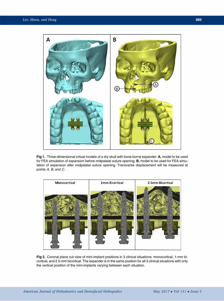
Fig 1. Three-dimensional virtual models of a dry skull with bone-borne expander: A,model to be usedfor FEA simulation of expansion before midpalatal suture opening; B, model to be used for FEA simu-lation of expansion after midpalatal suture opening. Transverse displacement will be measured atpoints A, B, and C.
Fig 2. Coronal plane cut view of mini-implant positions in 3 clinical situations: monocortical, 1-mm bi-cortical, and 2.5-mm bicortical. The expander is in the same position for all 3 clinical situations with onlythe vertical position of the mini-implants varying between each situation.
Lee, Moon, and Hong 889
American Journal of Orthodontics and Dentofacial Orthopedics May 2017 � Vol 151 � Issue 5

Table I. Material properties
Young's modulus (MPa) Poisson's ratioCortical bone 13,700 0.30Cancellous bone 1,370 0.30Suture 10 0.49Masticatory mucosa 25 0.30Titanium 113,000 0.33Stainless steel 210,000 0.30
890 Lee, Moon, and Hong
Tetrahedral elements were used for volumetric meshgeneration. Each skull was composed of about4,500,000 elements and 1,200,000 nodes. For the skullgeneration, the maxilla and the sutures were locally re-meshed to contain more fine elements than elsewhereon the skull. Each mini-implant was composed of about85,000 elements and 16,000 nodes. The expander wascomposed of approximately 30,000 elements and9,000 nodes.
The finite element models of the skull, mini-implants, and expander were imported into AbaqusFEA software (version 6.13; Dassault Systemes) toperform FEA simulations. The material properties usedare shown in Table I.37,45,46 Each material wasconsidered to be homogeneous and isotropic. Theboundary conditions applied were setting the nodes ofthe foramen magnum to be completely fixed in alldegrees of freedom.47
In the model simulating bone-borne expansionbefore midpalatal suture opening, the expander wasactivated transversely by 0.5 mm in the transverse planeand was unfixed in the sagittal and coronal planes toprevent interference with the resultant movement.37,38
In the model simulating bone-borne expansion aftermidpalatal suture opening, the expander was activatedtransversely by 0.25 mm for 20 steps resulting in a totalof 5 mm of expansion. Similar to the first model, theexpansion was also activated in the transverse planeand was unfixed in the sagittal and coronal planes toprevent interference with the resultant movement. Inboth models, Von Mises stress distribution and trans-verse displacement were evaluated.
RESULTS
Von Mises stress at the peri-implant site wasmeasured for the skull model containing the interlockingmidpalatal suture and was found to be clearly higher inthe monocortical anchorage model compared with bothbicortical anchorage models (Fig 3). In all models, theVon Mises stress was localized around the initial corticalbone layer. Minimal difference was observed betweenthe 1-mm and the 2.5-mm bicortical models. The totalVon Mises stress at the bone-implant interface was
May 2017 � Vol 151 � Issue 5 American
calculated for each model: 476,000 MPa for the mono-cortical model, 234,000 MPa for the 1-mm bicorticalmodel, and 227,000 MPa for the 2.5-mm bicorticalmodel. The difference between the monocortical modeland the 1-mm bicortical model was 68.17%, whereas thedifference between the monocortical model and the 2.5-mm bicortical model was 70.84%, and that between the1-mm and 2.5-mm bicortical models was 3.04%.
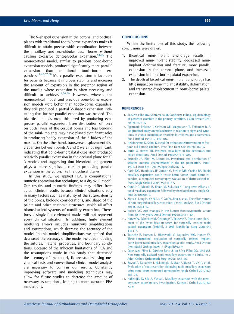
Von Mises stress of the mini-implants was alsomeasured in the skull model containing the interlockingmidpalatal suture and was found to be significantlyhigher in the monocortical model compared with both bi-cortical anchorage models (Fig 4). In all models, the VonMises stress on the implant was localized at the bone-implant interface around the initial cortical bone layer.Total Von Mises stress values were measured at thebone-implant interface and were determined to be5,831,000 MPa for the monocortical model,3,576,000 MPa for the 1-mm bicortical model, and3,845,000 MPa for the 2.5-mm bicortical model. The dif-ference between the monocortical model and the 1-mmbicortical model was 47.94%, the difference betweenthe monocortical model and the 2.5-mm bicortical modelwas 41.05%, and that between the 1-mm and the 2.5-mm bicortical models was 7.25%. For the monocorticalmodel, the maximum principal stress at the bone-implant interface was 664.49 MPa, and the minimumprincipal stress was 229.94 MPa. For the 1-mm bicorticalmodel, the maximum principal stress at the bone-implantinterface was 270.246 MPa, and the minimum principalstress was 53.95 MPa. For the 2.5-mm bicortical model,the maximum principal stress at the bone-implant inter-face was 289.87 MPa, and the minimum principal stresswas 75.94 MPa. Bending of the mini-implants was clearlyevident. Bending in all 3 mini-implants was measured forall 3 models, and the mean amounts of bending werecalculated to be 4.55� for the monocortical model,1.94� for the 1-mm bicortical model, and 1.71� for the2.5-mm bicortical model.
Transverse displacement was measured on the leftside of the skull model not containing an interlockingmidpalatal suture and was determined for each step,20 steps in total (Fig 5). These 20 steps were equivalentto 20 turns of 0.25 mm each, for a total of 5 mm ofexpansion (2.5 mm on each side). Left-side transversedisplacement was measured at points A, B, and C (Fig1, B) and plotted in Figure 6. The total and mean trans-verse displacements are recorded in Table II. At point A,the total transverse displacements were 1.608 mm forthe monocortical model, 1.988 mm for the 1-mm bicort-ical model, and 2.067 mm for the 2.5-mm bicorticalmodel. The difference at point A for total transversedisplacement between the monocortical model and the
Journal of Orthodontics and Dentofacial Orthopedics
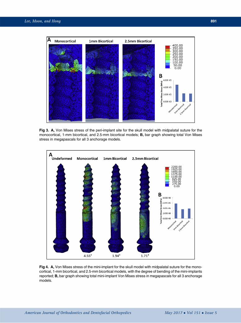
Fig 3. A, Von Mises stress of the peri-implant site for the skull model with midpalatal suture for themonocortical, 1-mm bicortical, and 2.5-mm bicortical models; B, bar graph showing total Von Misesstress in megapascals for all 3 anchorage models.
Fig 4. A, Von Mises stress of the mini-implant for the skull model with midpalatal suture for the mono-cortical, 1-mm bicortical, and 2.5-mm bicortical models, with the degree of bending of the mini-implantsreported; B, bar graph showing total mini-implant Von Mises stress in megapascals for all 3 anchoragemodels.
Lee, Moon, and Hong 891
American Journal of Orthodontics and Dentofacial Orthopedics May 2017 � Vol 151 � Issue 5

Fig 5. Frontal and occlusal views of step 20 (5 mm of expansion) of the skull model simulation aftermidpalatal suture opening with a contour map showing transverse displacement.
892 Lee, Moon, and Hong
1-mm bicortical model was 21.13%, the difference be-tween the monocortical model and the 2.5-mm bicorti-cal model was 24.98%, and that between the 1-mm andthe 2.5-mm bicortical models was 3.90%. At point B, thetotal transverse displacements were 2.215 mm for themonocortical model, 2.744 mm for the 1-mm bicorticalmodel, and 2.848 mm for the 2.5-mm bicortical model.The difference at point B for total transverse displace-ment between the monocortical model and the 1-mmbicortical model was 21.33%, the difference betweenthe monocortical model and the 2.5-mm bicorticalmodel was 25.00%, and that between the 1-mm andthe 2.5-mm bicortical models was 3.72%. At point C,the total transverse displacements were 1.141 mm forthe monocortical model, 1.444 mm for the 1-mm bicort-ical model, and 1.442 mm for the 2.5-mm bicorticalmodel. The difference at point A for total transversedisplacement between the monocortical model and the1-mm bicortical model was 23.44%, the difference be-tween the monocortical model and the 2.5-mm bicorti-cal model was 23.31%, and that between the 1-mm andthe 2.5-mm bicortical models was 0.14%.
The total transverse displacement at step 20 wasmeasured at levels D and E, located at the coronal mid-plane of the bone-borne palatal expander (Fig 7). The ra-tio between D and E was calculated to compare theamount of displacement measured at levels D and E.The closer the ratio was to 1.000, the more parallel theexpansion. The ratios were 0.634 for the monocorticalmodel, 0.692 for the 1-mm bicortical model, and
May 2017 � Vol 151 � Issue 5 American
0.701 for the 2.5-mm bicortical model. The differencebetween the monocortical model and 1-mm bicorticalmodel was 8.72%, the difference between the mono-cortical model and the 2.5-mm bicortical model was10.06%, and that between the 1-mm and the 2.5-mmbicortical models was 1.34%.
DISCUSSION
Bone-borne palatal expanders have been shown tobe a viable treatment option to correct a transversemaxillary deficiency in adults in several reports showingevidence of clinical success.18-21,48-50 Since bone-borneexpanders rely on skeletal anchorage obtained by mini-implants applying force directly to the basal bone, mini-implant stability is integral to successful skeletalorthopedic expansion. Bicortical mini-implantanchorage has been demonstrated to be superiorcompared with monocortical mini-implant anchoragefor orthodontic tooth movement but has not beenexplored for bone-borne palatal expansion.32,36
Therefore, this study was designed to evaluate whetherbicortical anchorage likewise increased stability andimproved skeletal orthopedic expansion compared withmonocortical anchorage.
We used 2 skull models to study the effects of bicort-ical and monocortical anchorage before and after mid-palatal suture opening. The midpalatal suture wasremoved in the model that represented postmidpalatalsuture opening to allow for expansion in the FEA simu-lation. Three clinical situations of varying mini-implant
Journal of Orthodontics and Dentofacial Orthopedics

Fig 6. Line graphs showing transverse displacement at each step during expansion.
Table II. Left-side transverse displacements (mm) after midpalatal suture opening
MonocorticalA
MonocorticalB
MonocorticalC
Bicortical1-mm A
Bicortical1-mm B
Bicortical1-mm C
Bicortical2.5-mmA
Bicortical2.5-mm B
Bicortical2.5-mm C
Total 1.608 2.215 1.141 1.988 2.744 1.444 2.067 2.848 1.442Mean 0.080 0.111 0.057 0.099 0.137 0.072 0.103 0.142 0.072
Fig 7. Cut view at the coronal midplane of the bone-borne palatal expander. Total displacements atlevels D and E were measured for each model.
Lee, Moon, and Hong 893
American Journal of Orthodontics and Dentofacial Orthopedics May 2017 � Vol 151 � Issue 5

894 Lee, Moon, and Hong
insertion depth were used for both skull models: amonocortical model, a 1-mm bicortical model, and a2.5-mm bicortical model. In all 3 clinical situations,the expander was in the same position, and only themini-implants varied in vertical position. All 3 of theseclinical situations have been observed in patients treatedat the University of California at Los Angeles School ofDentistry and were chosen to explore the differences be-tween monocortical and bicortical anchorage as well asto determine whether the depth of bicortical anchorageis significant. Operator experience may also play a role inthe varying depths of implantation seen clinically andhas been reported to be a factor in mini-implant stabil-ity.27,29
Overloading of the peri-implant bone can lead to lossof primary stability of orthodontic mini-implants.51 Inaddition, there is a decreased risk of mini-implant loos-ening if the stress in the cervical region of theperi-implant bone region is low.52 In the skull modelcontaining the midpalatal suture, this study demon-strated that there is significantly lower stress at theperi-implant site in the bicortical models comparedwith the monocortical model, suggesting that mini-implants placed bicortically decrease the risk of mini-implant loosening. Minimal differences were observedbetween the 2 bicortical models. These findings areconsistent with previous studies showing that in bone-borne expansion, bicortical anchorage is more favorablethan monocortical anchorage and that the depth of bi-cortical anchorage has a minimal impact on stabil-ity.32,36 In addition, this finding is also supportedthrough Wolff's law and the maximum principal stressvalues reported in this study.53 The monocortical modelhad an increased maximum principal stress valuecompared with the bicortical models. A high principalstress value, as in the monocortical model, may placethe bone remodeling in the “pathologic overload win-dow” in which stress fractures and bone resorption,not coupled to formation, occur, leading to overloadedimplants and implant loosening.
A greater magnitude of force experienced by mini-implants increases the likelihood of deformation andmini-implant fracture.54 The authors of this study foundthat monocortical mini-implants experienced signifi-cantly greater stress at the bone-implant interface, spe-cifically around the initial cortical bone layer, comparedwith bicortical mini-implants. There were minimal dif-ferences between the mini-implant stress levels of the2 bicortical models. In addition, the monocorticalmini-implants were found to have more than doublethe bending compared with the 2 bicortical models.Again, there was a minimal difference between thebending in the 2 bicortical models. These findings
May 2017 � Vol 151 � Issue 5 American
suggest that mini-implant fracture is most likely to occurat the initial cortical bone layer and demonstrate thatmini-implant deformation and fracture in bone-borneexpansion are more likely to occur with monocorticalanchorage rather than bicortical anchorage and thatthe depth of bicortical anchorage has little impact onmini-implant deformation and fracture.
Transverse displacement was measured in the skullmodel that did not contain the interlocking midpalatalsuture for 20 steps. Each step was equivalent to a0.25-mm turn of the palatal expander for a total of5 mm of simulated expansion. Analyzing the bone-borne expansion for multiple turns of the expander al-lowed for more in-depth analysis than previous FEAstudies of expansion using only 1 static step. Further-more, this stepwise model was more representative of aclinical situation.
Transverse displacement was found to be signifi-cantly lower in the monocortical model at all 3 pointsof measurement and after every turn compared withboth bicortical models. Minimal differences in transversedisplacements were observed between the 2 bicorticalmodels. The difference in transverse displacement be-tween the monocortical and bicortical models may bedue to the greater surface contact area in cortical boneof the bicortical models; this allowed for more uniformforce transfer. Mini-implant contact surface area incortical bone has been shown to be a more significantcontributor to mini-implant stability than cancellousbone.33,55 In addition, the monocortical model mayhave experienced less transverse displacement becauseof its increased bending. This increased amount ofbending created a greater discrepancy between themini-implant orientation and the line of applied force.Any discrepancy between mini-implant orientation andline of applied force has been shown to decrease loaddistribution uniformity leading to disproportionateload distribution at the bone-implant interface thatwould most likely decrease transverse displacement.56
These findings therefore demonstrate that bicorticalanchorage leads to increased expansion compared withmonocortical anchorage and that the depth of bicorticalanchorage has minimal impact on the amount of expan-sion.
The ratios between levels D and E were significantlygreater for both bicortical models compared with themonocortical model. There was a minimal difference be-tween the ratios of the 2 bicortical models. A larger ratiobetween levels D and E indicated more parallel expan-sion in the coronal plane. These results demonstratethat bicortical engagement produces more parallelexpansion of the maxillary complex in the coronal planecompared with monocortical engagement.
Journal of Orthodontics and Dentofacial Orthopedics
Lee, Moon, and Hong 895
The V-shaped expansion in the coronal and occlusalplanes with traditional tooth-borne expanders makes itdifficult to attain precise width coordination betweenthe maxillary and mandibular basal bones withoutcausing excessive dentoalveolar expansion.54,55 Themonocortical model, similar to previous bone-borneexpansion models, produced significantly more parallelexpansion than traditional tooth-borne ex-panders.11,45,57,58 More parallel expansion is favorablefor patients because it improves stability and increasesthe amount of expansion in the posterior region ofthe maxilla where expansion is often necessary anddifficult to achieve.11,56,59 However, whereas themonocortical model and previous bone-borne expan-sion models were better than tooth-borne expanders,they still produced a partial V-shaped expansion indi-cating that further parallel expansion was needed. Thebicortical models meet this need by producing evengreater parallel expansion. Even distribution of forceon both layers of the cortical bones and less bendingof the mini-implants may have played significant rolesin producing bodily expansion of the 2 halves of themaxilla. On the other hand, transverse displacement dis-crepancies between points A and C were not significant,indicating that bone-borne palatal expansion producedrelatively parallel expansion in the occlusal plane for all3 models and suggesting that bicortical engagementplays a more significant role in producing parallelexpansion in the coronal vs the occlusal planes.
In this study, we applied FEA, a computationalnumeric approximation technique, to a dry skull model.Our results and numeric findings may differ fromactual clinical results because clinical situations varyin many factors such as maturity of the suture, densityof the bones, biologic considerations, and shape of thepalate and other anatomic structures, which all affectbiomechanical systems of maxillary expansion. There-fore, a single finite element model will not representevery clinical situation. In addition, finite elementmodeling always includes numerous simplificationsand assumptions, which decrease the accuracy of themodel. In this model, simplifications we applied thatdecreased the accuracy of the model included modelingthe sutures, material properties, and boundary condi-tions. Because of the inherent limitations of FEA andthe assumptions made in this study that decreasedthe accuracy of the model, future studies using me-chanical tests and conventional clinical model analysisare necessary to confirm our results. Constantlyimproving software and modeling techniques mayallow for future studies to decrease the amount ofnecessary assumptions, leading to more accurate FEAsimulations.
American Journal of Orthodontics and Dentofacial Orthoped
CONCLUSIONS
Within the limitations of this study, the followingconclusions were drawn.
1. Bicortical mini-implant anchorage results inimproved mini-implant stability, decreased mini-implant deformation and fracture, more parallelexpansion in the coronal plane, and increasedexpansion in bone-borne palatal expansion.
2. The depth of bicortical mini-implant anchorage haslittle impact on mini-implant stability, deformation,and transverse displacement in bone-borne palatalexpansion.
REFERENCES
1. da Silva Filho OG, Santamaria M, Capelozza Filho L. Epidemiologyof posterior crossbite in the primary dentition. J Clin Pediatr Dent2007;32:73-8.
2. Egermark-Eriksson I, Carlsson GE, Magnusson T, Thilander B. Alongitudinal study on malocclusion in relation to signs and symp-toms of cranio-mandibular disorders in children and adolescents.Eur J Orthod 1990;12:399-407.
3. Heikinheimo K, Salmi K. Need for orthodontic intervention in five-year-old Finnish children. Proc Finn Dent Soc 1987;8:165-9.
4. Kutin G, Hawes RR. Posterior cross-bites in the deciduous andmixed dentitions. Am J Orthod 1969;56:491-504.
5. Brunelle JA, Bhat M, Lipton JA. Prevalence and distribution ofselected occlusal characteristics in the US population, 1988-1991. J Dent Res 1996;75(Spec No):706-13.
6. Garib DG, Henriques JF, Janson G, Freitas MR, Coelho RA. Rapidmaxillary expansion—tooth tissue-borne versus tooth-borne ex-panders: a computed tomography evaluation of dentoskeletal ef-fects. Angle Orthod 2005;75:548-57.
7. Gurel HG, Memili B, Erkan M, Sukurica Y. Long-term effects ofrapid maxillary expansion followed by fixed appliances. Angle Or-thod 2010;80:5-9.
8. Zhou Y, Long H, Ye N, Liu Y, Xu W, Jing Y, et al. The effectivenessof non-surgical maxillary expansion: a meta-analysis. Eur J Orthod2014;36:233-42.
9. Kokich VG. Age changes in the human frontozygomatic suturefrom 20 to 95 years. Am J Orthod 1976;69:411-30.
10. Harzer W, Schneider M, Gedrange T, Tausche E. Direct bone place-ment of the hyrax fixation screw for surgically assisted rapidpalatal expansion (SARPE). J Oral Maxillofac Surg 2006;64:1313-7.
11. Tausche E, Hansen L, Hietschold V, Lagrav�ere MO, Harzer W.Three-dimensional evaluation of surgically assisted implantbone-borne rapid maxillary expansion: a pilot study. Am J OrthodDentofacial Orthop 2007;131(Suppl):S92-9.
12. Capelozza Filho L, Cardoso Neto J, da Silva Filho OG, Ursi WJ.Non-surgically assisted rapid maxillary expansion in adults. Int JAdult Orthod Orthognath Surg 1996;11:57-66.
13. Baysal A, Karadede I, Hekimoglu S, Ucar F, Ozzer T, Veli I, et al.Evaluation of root resorption following rapid maxillary expansionusing cone-beam computed tomography. Angle Orthod 2012;82:488-94.
14. Halicio�glu K, Kiki A, Yavuz I. Maxillary expansion with the mem-ory screw: a preliminary investigation. Korean J Orthod 2012;42:73-9.
ics May 2017 � Vol 151 � Issue 5

896 Lee, Moon, and Hong
15. Shetty V, Caridad JM, Caputo AA, Chaconas SJ. Biomechanicalrationale for surgical-orthodontic expansion of the adult maxilla.J Oral Maxillofac Surg 1994;52:742-9.
16. Byloff FK, Mossaz CF. Skeletal and dental changes following surgi-cally assisted rapid palatal expansion. Eur J Orthod 2004;26:403-9.
17. Gauthier C, Voyer R, Paquette M, Rompr�e P, Papadakis A. Peri-odontal effects of surgically assisted rapid palatal expansion eval-uated clinically and with cone-beam computerized tomography:6-month preliminary results. Am J Orthod Dentofacial Orthop2011;139(Suppl):S117-28.
18. Lee KJ, Park YC, Park JY, Hwang WS. Miniscrew-assisted nonsur-gical palatal expansion before orthognathic surgery for a patientwith severe mandibular prognathism. Am J Orthod Dentofacial Or-thop 2010;137:830-9.
19. Kim KB, Helmkamp ME. Miniscrew implant-supported rapidmaxillary expansion. J Clin Orthod 2012;46:608-12.
20. Garib DG, Navarro RDL, Francischone CE, Oltramari PV. Rapidmaxillary expansion using palatal implants. J Clin Orthod 2008;42:665-71.
21. Lagrav�ere MO, Carey J, Heo G, Toogood RW, Major PW. Trans-verse, vertical, and anteroposterior changes from bone-anchoredmaxillary expansion vs traditional rapid maxillary expansion: arandomized clinical trial. Am J Orthod Dentofacial Orthop 2010;137:304.e1-12.
22. Tausche E, Hansen L, Schneider M, Harzer W. Bone-supportedrapid maxillary expansion with an implant-borne hyrax screw:the Dresden distractor. Orthod Fr 2008;79:127-35.
23. Carlson C, Sung J, McComb RW, Machado AW, Moon W. Micro-implant-assisted rapid palatal expansion appliance to orthopedi-cally correct transverse maxillary deficiency in an adult. Am J Or-thod Dentofacial Orthop 2016;149:716-28.
24. Lin L, Ahn HW, Kim SJ, Moon SC, Kim SH, Nelson G. Tooth-bornevs bone-borne rapid maxillary expanders in late adolescence.Angle Orthod 2015;85:253-62.
25. Wilmes B, Nienkemper M, Drescher D. Application and effective-ness of a mini-implant- and tooth-borne rapid palatal expansiondevice: the hybrid hyrax. World J Orthod 2010;11:323-30.
26. Crismani AG, Bertl MH, Celar AG, Bantleon HP, Burstone CJ.Miniscrews in orthodontic treatment: review and analysis of pub-lished clinical trials. Am J Orthod Dentofacial Orthop 2010;137:108-13.
27. Lim HJ, Choi YJ, Evans CA, Hwang HS. Predictors of initial stabilityof orthodontic miniscrew implants. Eur J Orthod 2011;33:528-32.
28. Wu TY, Kuang SH, Wu CH. Factors associated with the stability ofmini-implants for orthodontic anchorage: a study of 414 samplesin Taiwan. J Oral Maxillofac Surg 2009;67:1595-9.
29. Kim YH, Yang SM, Kim S, Lee JY, Kim KE, Gianelly AA, et al. Mid-palatal miniscrews for orthodontic anchorage: factors affectingclinical success. Am J Orthod Dentofacial Orthop 2010;137:66-72.
30. Miyawaki S, Koyama I, Inoue M, Mishima K, Sugahara T, Takano-Yamamoto T. Factors associated with the stability of titaniumscrews placed in the posterior region for orthodontic anchorage.Am J Orthod Dentofacial Orthop 2003;124:373-8.
31. Wu Y, Xu Z, Tan L, Zhao Z, Yang P, Li Y, et al. Orthodontic mini-implant stability under continuous or intermittent loading: a his-tomorphometric and biomechanical analysis. Clin Implant DentRelat Res 2015;17:163-72.
32. Holberg C, Winterhalder P, Rudzki-Janson I, Wichelhaus A. Finiteelement analysis of mono- and bicortical mini-implant stability.Eur J Orthod 2014;36:550-6.
33. Hong C, Lee H, Webster R, Kwak J, Wu BM, Moon W. Stabilitycomparison between commercially available mini-implants and anovel design: part 1. Angle Orthod 2011;81:692-9.
May 2017 � Vol 151 � Issue 5 American
34. Hong C, Truong P, Song HN, Wu BM, Moon W. Mechanical stabil-ity assessment of novel orthodontic mini-implant designs: part 2.Angle Orthod 2011;81:1001-9.
35. Song HN, Hong C, Banh R, Ohebsion T, Asatrian G, Leung HY, et al.Mechanical stability and clinical applicability assessment of novelorthodontic mini-implant design. Angle Orthod 2013;83:832-41.
36. Brettin BT, Grosland NM, Qian F, Southard KA, Stuntz TD,Morgan TA, et al. Bicortical vs monocortical orthodontic skeletalanchorage. Am J Orthod Dentofacial Orthop 2008;134:625-35.
37. Lee SC, Park JH, Bayome M, Kim KB, Araujo EA, Kook YA. Effect ofbone-borne rapid maxillary expanders with and without surgicalassistance on the craniofacial structures using finite element anal-ysis. Am J Orthod Dentofacial Orthop 2014;145:638-48.
38. Lee HK, Bayome M, Ahn CS, Kim SH, Kim KB, Mo SS, et al. Stressdistribution and displacement by different bone-borne palatal ex-panders with micro-implants: a three-dimensional finite-elementanalysis. Eur J Orthod 2014;36:531-40.
39. Boryor A, Hohmann A, Wunderlich A, Geiger M, Kilic F, Kim KB,et al. Use of a modified expander during rapid maxillary expansionin adults: an in vitro and finite element study. Int J Oral MaxillofacImplants 2013;28:e11-6.
40. MacGinnis M, Chu H, Youssef G, Wu KW, Machado AW, Moon W.The effects of micro-implant assisted rapid palatal expansion(MARPE) on the nasomaxillary complex—a finite element method(FEM) analysis. Prog Orthod 2014;15:52.
41. Moon W, Wu KW, MacGinnis M, Sung J, Chu H, Youssef G, et al.The efficacy of maxillary protraction protocols with the micro-implant-assisted rapid palatal expander (MARPE) and the novelN2mini-implant—a finite element study. Prog Orthod 2015;16:16.
42. Soboleski D, McCloskey D, Mussari B, Sauerbrei E, Clarke M,Fletcher A. Sonography of normal cranial sutures. AJR Am J Roent-genol 1997;168:819-21.
43. Farnsworth D, Rossouw PE, Ceen RF, Buschang PH. Cortical bonethickness at common miniscrew implant placement sites. Am J Or-thod Dentofacial Orthop 2011;139:495-503.
44. Studer SP, Allen EP, Rees TC, Kouba A. The thickness of mastica-tory mucosa in the human hard palate and tuberosity as potentialdonor sites for ridge augmentation procedures. J Periodontol1997;68:145-51.
45. Ludwig B, Baumgaertel S, Zorkun B, Bonitz L, Glasl B, Wilmes B,et al. Application of a new viscoelastic finite element methodmodel and analysis of miniscrew-supported hybrid hyrax treat-ment. Am J Orthod Dentofacial Orthop 2013;143:426-35.
46. Goktas S, Dmytryk JJ, McFetridge PS. Biomechanical behavior oforal soft tissues. J Periodontol 2011;82:1178-86.
47. Gautam P, Valiathan A, Adhikari R. Stress and displacement pat-terns in the craniofacial skeleton with rapid maxillary expansion:a finite element method study. Am J Orthod Dentofacial Orthop2007;132:5.e1-11.
48. Ngan P, Moon W. Evolution of Class III treatment in orthodontics.Am J Orthod Dentofacial Orthop 2015;148:22-36.
49. Moon W, Khulla R. Class III orthopedic treatment with skeletalanchorage. Potomac, Md: Bentham eBooks; 2014. p. 116-50.
50. Moon W. An interview with Won Moon. Dental Press J Orthod2013;18:12-28.
51. Singh S, Mogra S, Shetty VS, Shetty S, Philip P. Three-dimensionalfinite element analysis of strength, stability, and stress distributionin orthodontic anchorage: a conical, self-drilling miniscrewimplant system. Am J Orthod Dentofacial Orthop 2012;141:327-36.
52. Florvaag B, Kneuertz P, Lazar F, Koebke J, Zoller JE, Braumann B,et al. Biomechanical properties of orthodontic miniscrews. An in-vitro study. J Orofac Orthop 2010;71:53-67.
Journal of Orthodontics and Dentofacial Orthopedics

Lee, Moon, and Hong 897
53. Frost HM. Wolff's law and bone's structural adaptations to mechan-ical usage: an overview for clinicians. AngleOrthod1994;64:175-88.
54. Pithon MM, Figueiredo DS, Oliveira DD. Mechanical evaluation oforthodontic mini-implants of different lengths. J Oral MaxillofacSurg 2013;71:479-86.
55. Motoyoshi M, Inaba M, Ono A, Ueno S, Shimizu N. The effect ofcortical bone thickness on the stability of orthodontic mini-implants and on the stress distribution in surrounding bone. IntJ Oral Maxillofac Surg 2009;38:13-8.
56. Pickard MB, Dechow P, Rossouw PE, Buschang PH. Effects ofminiscrew orientation on implant stability and resistance to fail-ure. Am J Orthod Dentofacial Orthop 2010;137:91-9.
American Journal of Orthodontics and Dentofacial Orthoped
57. Garrett BJ, Caruso JM, Rungcharassaeng K, Farrage JR,Kim JS, Taylor GD. Skeletal effects to the maxilla afterrapid maxillary expansion assessed with cone-beamcomputed tomography. Am J Orthod Dentofacial Orthop2008;134:8-9.
58. Lee H, Ting K, Nelson M, Sun N, Sung SJ. Maxillary expansion incustomized finite element method models. Am J Orthod Dentofa-cial Orthop 2009;136:367-74.
59. Ghoneima A, Abdel-Fattah E, Hartsfield J, El-Bedwehi A, Kamel A,Kula K. Effects of rapid maxillary expansion on the cranial and cir-cummaxillary sutures. Am J Orthod Dentofacial Orthop 2011;140:510-9.
ics May 2017 � Vol 151 � Issue 5