Effects of high accelerations and heat fluxes on …...cylindrical copper boiler, 4.0 inches (10.2...
61
NASA TECHNICAL NOTE \ 4 v) a z EFFECTS OF HIGH ACCELERATIONS AND HEAT FLUXES ON NUCLEATE BOILING OF WATER IN AN AXISYMMETRIC ROTATING BOILER https://ntrs.nasa.gov/search.jsp?R=19710014726 2020-04-25T17:42:52+00:00Z
Transcript of Effects of high accelerations and heat fluxes on …...cylindrical copper boiler, 4.0 inches (10.2...

NASA TECHNICAL NOTE
\
4 v) a z
EFFECTS OF HIGH ACCELERATIONS AND HEAT FLUXES ON NUCLEATE BOILING OF WATER IN A N AXISYMMETRIC ROTATING BOILER
https://ntrs.nasa.gov/search.jsp?R=19710014726 2020-04-25T17:42:52+00:00Z
TECH LIBRARY KAFB, NM
Lewis Research Center National Aeronautics and Space Administration Cleveland, Ohio 44135 ~
12. Sponsoring Agency Name and Address
i I t iii t ti ti t i tin iiill iii t iii ti iiiii I ti iiii
13. Type of Report and Period Covered
Technical Note
- . - I 1. Report No. I 2. Government Accession No. I 3. Recipient” 0 L 3 3 L 0 9
I 16. Abstract
Stable boiling in a rotating cylindrical annulus with continuous through-flow of water was ob- tained at heat fluxes as high as 818 000 Btu/(hr)(ft2) (2. 58 MW/m ) at atmospheric pressure. Incipient- and nucleate -boiling heat -transfer coefficients were obtained at accelerations up to 400 g’s. Measurements were made of void fractions, radial temperature profiles, and wall p ressures in the boiling fluid. Convective secondary-flow cel ls and fluid temperature inver - sions were revealed. Increased fluid thicknesses increased heat- t ransfer coefficients, but inlet liquid subcooling had no effect. Coefficients increased with acceleration at low heat fluxes, but at high fluxes varied l e s s than the usual data scat ter .
2
I
17. Key Words (Suggested by Author(s) )
Boiling heat t ransfer . Acceleration effects on boiling Rotating boiler
18. Distr ibution Statement
Unclassified - unlimited
I
21. NO. of Pages 22. Price* 1 ~ 59 I $3.00 19. Security Classif. (of this report) 20. Security Classif. (of this page)
Unclassified I .. - Unclassified
F o r sale by t h e Na t iona l Technical I n f o r m a t i o n Service, Springfield, V i rg in ia 22151
i
I

EFFECTS OF HIGH ACCELERATIONS AND HEAT FLUXES ON NUCLEATE
BOILING OF WATER IN AN AXISYMMI3RIC ROTATING BOILER
by P a u l J. Mar to* a n d V e r n o n H. Gray
Lewis Research C e n t e r
SUMMARY
Nucleate -boiling data were obtained using a heated-wall rotating boiler with conti -
Heat fluxes as nuous through-flow of water as the test fluid. The boiler was rotated at speeds up to 2660 rpm, giving radial accelerations up to 400 g's at the test surface. high as 818 000 Btu per hour per square foot (2. 58 MW/m ) were attained with stable boiling at atmospheric pressure. fluid were measured. effects diminished with time.
2
Radial temperature profiles in the two-phase boiling Effects of aging of the test surface were noted; however, these
Visual observation of the boiling two-phase fluid annulus revealed secondary flow cell circulation which increased with acceleration and was also influenced by inlet liquid feed and by heat f lux level. Bubble nucleation at the heated surface was sharply re- duced at high accelerations with corresponding increases in local fluid subcoolings and decreases in measured average vapor void fractions in the fluid annulus. The inlet water subcooling had no measurable effect on boiling heat transfer, but heat -transfer coefficients were increased by increases in the thickness of the two-phase fluid annulus.
For the inception of nucleate boiling from natural convection, the heat f l u x and re- quired wall superheat increased as the acceleration increased. heat-transfer coefficients increased with acceleration at low heat fluxes but were prac- tically independent of acceleration up to 400 g's a t very high heat fluxes.
For nucleate boiling,
INTRODUCTION
In an effort to increase the stability and heat-flux capability of pool boilers and v a w r generation devices, both in space and on Earth, the concept of a rotating boiler
*Assistant Professor of Mechanical Engineering, Naval Postgraduate School, - . .
Monterey, California; NASA Summer Faculty Fellow in 1968.

has been under study for several yea r s a t the Lewis Research Center (ref. 1). A small cylindrical copper boiler, 4 .0 inches (10.2 cm) in diameter and 2 . 0 inches (5.1 cni) high, has been constructed. Reference 2 descr ibes the operation of this boiler, present- ing boiling heat-transfer coefficients a t accelerations up to 200 g's. Photographic data up to 475 g's and a motion picture film supplement, which show the effects of rotation on boiling and liquid-vapor separation, a r e a l so included.
cross-over trend in the data, in which an increase in acceleration increased the heat- transfer coefficients at low heat fluxes but decreased them slightly at high heat fluxes. This trend ag rees with the ear l ie r data of Merte and Clark (ref. 3), which were taken at accelerations up to 20 g's. Both their data and the data of reference 2 were obtained using saturation temperatures at the boiler wall. These temperatures were not meas- ured but were calculated using the estimated increase in hydrostatic pressure at the boiler wall due to acceleration. In the case of reference 2, however, this hydrostatic pressure increase was based upon the measured two-phase fluid annular thickness. The boiling fluid was assumed to be all liquid in the calculations because the t rue two-phase fluid density (or void fraction) was not known. This assumption of all liquid in the boiler resulted in an uncertainty in the converted experimental data, particularly a t the higher accelerations and heat fluxes. In addition, the experimental resu l t s of reference 2 may have been influenced by variations in liquid inlet subcooling and boiler fluid level, which were not controlled during operation.
by recent contributions to the heat-transfer literature. Pool-boiling heat-transfer coefficients in water were reported at accelerations up to 134 g's by Adelberg and Schwartz in reference 4. In their experiments, a container of water with a heater ribbon immersed in it was rotated on a centrifuge a r m . Costello and Tuthill (ref. 5) show that over the gravity range of 1 to 134 g's, gravity has an effect upon nucleate boiling only through the local variation in hydrostatic head at the test surface, and when the data a r e plotted using the saturation temperature a t the boiler wall, all the data may be represented by a single curve with no cross-over trend. However, their data do show considerable scatter, and they point out that "one should not rule out the possibility of observing an effect of gravity upon nucleate boiling at sufficiently high g levels. " Experimental pool-boiling data, obtained in a s imilar manner, using water and Arcton 11 (similar to Freon), were presented at accelerations to 65 g's by Turton in reference 6. H i s data are plotted using wall-to-bulk temperature differences, and he concludes that acceleration has little effect upon the temperature dif - ference (and therefore heat-transfer coefficient) in nucleate boiling for heat fluxes up to 60 000 Btu per hour per square foot. Natural-convection and pool-boiling heat-transfer measurements using water in a 5.67-inch- (14. 4-cm-) diameter by 1. 0-inch- (2. 5-cm-)
The nucleate -boiling heat-transfer resu l t s obtained in reference 2 showed a definite
Effects of acceleration on nucleate boiling continue to be of interest, as evidenced
Their results and the data of
2
high centrifugal boiler were made a t accelerations to 1280 g's by Eschweiler, Benton, and Preckshot (ref. 7). Their nucleate-boiling data show a strong influence of gravity in the natural-convection-influenced boiling region, but no conclusions can be made re- garding a cross-over trend at higher heat fluxes.
The objectives of this investigation were therefore to obtain improved nucleate - boiling data fo r water in a rotating boiler with continuous through-flow of fluid by more accurately measuring the local temperature and surface -hydrostatic pressure witnin the boiling fluid; to extend data on boiling heat-transfer coefficients to accelerations and heat fluxes higher than those reported in reference 2; and to study, within the limitations of the existing apparatus, the effects of fluid level and liquid inlet subcooling on the boiling heat -transf er variables.
EQUIPMENT AND CALIBRATIONS
The test apparatus is shown schematically in figure 1. It was the same apparatus as that described in reference 2, but with several modifications.
Description of Equipment
Liquid supply system. - Demineralized triple-distilled water was used in the ex- periments; this water was stored in the large stainless-steel supply tank shown in fig- u r e 1. The distilled water was pressure-fed through a porous metal f i l ter and a micro- flow turbine-type flowmeter. Nitrogen g a s was used to pressurize the tank. The feed l ines were stainless-steel tubes with 3/8-inch (0.95-cm) outside diameter and were trace-heated with 1/4-inch (0.63 -cm) copper steam lines and wrapped with asbestos s t r ips .
An additional heat exchanger and storage tank were added subsequent to the refer- ence 2 tests to control more closely the liquid inlet temperature to the rotating boiler. A 0 . 3 8 -inch- (0.95-cm-) diameter stainless-steel helically wound coil, about 4.0 inches (10.2 cm) in diameter and 12.0 inches (30. 5 cm) high was wrapped with 1. 0-inch- (2. 5-cm-) wide fiberglass-insulated electrical heating tape. The outlet line of this heat exchanger coil was connected to the top of a 3.0-inch- (7.6-cm-) diameter by 12.0- inch- (30. 5-cm-) high stainless-steel storage vessel which was also electrically heated. The outlet line from this storage vessel was connected to the rotating face seal a t the bottom of the hollow shaft (see fig. 1).
cylinder, 2.0 inches (5. 1 cm) high. It was mounted on a vertical shaft and was designed Test boiler. - The test boiler was a 4. 0-inch- (10.2-cm-) inside-diameter copper ~______
3
to rotate a t variable speeds up to 3000 rpm.
vertical shaft, passed through a regulating valve,' and then sprayed out to the cylindrical walls, where it formed a liquid annulus. Feed liquid passed up into the heated zone through eight smal l holes (0.078 in. o r 0.198 cm in diameter) to replace the fluid that boiled off. These feed holes were located tangential to the boiler test surface. Vapor produced in the boiling process separated from the fluid annulus (because of centrifugal force) and flowed out the top of the boiler along the axis of rotation. the fluid annulus was controlled by the adjustable float-activated linkage to the regulat- ing valve.
The boiler was heated by an 11-gage Chromel-A wire in a 3/16-inch- (0.47-cm-) outside -diameter Inconel sheath with alumina insulation. wound and furnace-brazed into a r eces s in the outside of the cylindrical copper boiler wall. Fiberglass insulation was packed around the float chamber and heater coils to reduce heat losses. The copper heat-transfer surface of the boiler was hot wiped with a layer of pure tin about 5 mi ls (0.13 mm) thick pr ior to the present tests.
Clear preshrunk plastic windows were installed in the annular region on top of the boiler so that the liquid-vapor interface and the boiling action could be observed. As shown in figure 2, two annular windows, 0 .25 inch (0.63 cm) thick, were provided to allow accurate measurement of the liquid and two -phase fluid levels during operation. The design of these windows a l so permitted calculation of the average vapor void f r ac - tion in the two-phase fluid annulus. (0.079-cm-) diameter drilled holes tangential to the boiling test surface. These holes permitted liquid to flow up into the unheated, nonboiling, top annular space during op- eration.
diameter pipe assembly leading to the condenser. The condenser was a cubical metal box open to the atmosphere at the bottom. Four nozzles sprayed cold tap water into the condenser box.
A c ross section of the boiler is shown in figure 2. Liquid flowed upward inside the
The thickness of
This heater w a s helically
The bottom window contained three 0.031-inch-
The outlet vapor duct engaged a stationary felt rubbing seal in the 2-inch- (5 . l -cm-)
Instrumentation. - The boiling test instrumentation is shown schematically in fig - u r e s 1 and 2. Four thermocouples rotated with the boiler. Six leads (for three thermo- couples) were brought out of the rotating system through six silver sliprings a t the top of the vapor space. Each silver slipring made contact with two spring-loaded silver- graphite brushes which were constructed to permit only momentary contact with the sliprings in an effor t to reduce frictional heating. Because of facility limitations, the two leads f o r the fourth thermocouple were brought out of the rotating system through two less-accurate sliprings below the boiler.
joined to the copper wall with solder a t the end of a drilled hole 0.040 inch (0. 102 cm) The heated boiler wall thermocouple (T,) w a s a single 26-gage constantan wire
4
I l l I I I I

in diameter, 1 . 0 inch (2. 5 cm) up from the bottom of the heated cylinder, and 0. 098k 0. 002 inch (0.25kO. 005 cm) from the cylinder inside diameter. in the appendix. ) The heated wall surface temperature was obtained by calculation with known values of the copper conductivity, the heat flux, and the thermocouple location. The other three rotating thermocouples were 30-gageY two-wire, copper -constantan, glass-insulated, metal-sheathed (0.062-in. or 0.16-cm od) assemblies with exposed ball junctions. The second rotating thermocouple (T the two-phase boiling fluid at a point 0.13 inch (0.32 cm) radially inward from the heated wall surface and 1.0 inch (2. 5 cm) up from the bottom. Provisions were also made to vary the radial position of this thermocouple while keeping it alined circumferentially with the boiler wall thermocouple. The third rotating thermocouple (Tin, l ) measured the temperature of the feed liquid about 0.12 inch (0.30 cm) from one of the inlets to the boiling test section. The fourth ( less accurate) rotating thermocouple (T ) measured the temperature of the nonboiling liquid in the annulus above the heated tes t section. thermocouple voltages for these circuits were recorded using a high -precision digital voltmeter. Rotating thermocouple circuitry is shown in more detail in reference 2. The exit vapor temperature was measured by a stationary sheathed thermocouple mounted just above the sliprings.
A 1.0-pound-per-square-inch (6.9-kN/m ) differential pressure transducer was connected to the top of the stationary outlet vapor container to record the pressure in the vapor space. Heat flow into the boiler was measured with a wattmeter calibrated to within kl. 5 percent e r r o r .
(All symbols are defined
) measured the temperature of 2Y
1 The
2
Calibrat ion Procedures
Heat-loss calibration. - To determine boiler heat losses, the inside of the boiler was packed with fiberglass insulation. The boiler was assembled exactly as for normal operation, but the water inlet valve was closed so that the boiler would be dry. steam from the 5-pound-per-square-inch- (35-kN/m -) gage building steam line was introduced at the boiler outlet to maintain the top sliprings at the saturated steam tem- perature. power level. The speed of the boiler was then varied at this power level. The system remained a t each speed setting until thermal equilibrium was reached; the temperature of the heated-wall thermocouple was then recorded. the amount of power put into the system was the same as that being lost. that this power was the same as the heat lost from the boiler during normal boiling operation a t this s a m e equilibrium wall temperature and speed. cedure for different heat inputs, the heat loss was obtained as a function of rotational
Saturated 2 .
The main heater was turned on, and the heat input was fixed at some low
At this equilibrium temperature, It was assumed
By repeating the pro-
5

speed for various equilibrium temperatures. At 250' F (395 K) equilibrium tempera - ture, the heat l o s s was never more than 135 watts. The calibrated heat loss was sub- tracted from the g r o s s power input to obtain the a t tua l heat f lux through the test surface.
P r e s s u r e transducer calibration. - The pressure transducer was calibrated in place over the range of 0 to 1 . 0 pound per square inch (6.9 kN/m ) gage by varying a known height of water above the transducer from 0 to 27.8 inches (70.6 cm). At each water level setting above the transducer, the output voltage of the transducer was recorded on a digital voltmeter. The response of the transducer was l inear with an output sensitivity of 0.35 millivolt per inch of water. pressure was introduced into the slipring vapor space to compensate for the transducer sensitivity to temperature.
Calibration of thermocouples. - Considerable care was exercised in calibrating the thermocouples. The entire outside of the boiler was packed with fiberglass insulation. Saturated steam from the 5 -pound -per -square -inch - (3 5 -kN/m -) gage building steam line was introduced into the boiler through the feed water inlet. The steam flowed past the bottom thermocouple sliprings, through the boiler, past the top thermocouple slip- rings, and out through the condenser. The stationary thermocouple in the vapor space was accurately checked by comparing its reading with the saturation temperature cal- culated from the measured pressure in the vapor space.
so that frictional heating effects at the slipring-brush junction were at a minimum level. (The tension of the bottom slipring brushes, fo r the nonboiling liquid annulus thermo- couple, could not be regulated. ) The top brushes were then moved away from their respective sliprings to avoid contact. The boiler speed was then successively s e t a t 515, 660, 940, 1330, 1880, and 2660 rpm (corresponding to 15, 25, 50, 100, 200, and 400 g's a t the heating surface, respectively). At each speed setting, the top brushes were placed against the sliprings, making contact momentarily. The momentary read- ings of the three rotating thermocouples using the top sliprings and the reading from the bottom sliprings were then compared with the reading of the stationary vapor space thermocouple. in the vapor space was recorded at each speed setting. This procedure was repeated several times, and after each time the slipring assembly was dismantled and reas- sembled. of about six deviations of each thermocouple from the saturated vapor temperature cal- culated f o r the measured pressure. This average deviation was either subtracted from o r added to each thermocouple reading during operation to a r r i v e a t a corrected thermo- couple voltage (or temperature). a t 220' F (378 K ) , a change of 0.026 millivolt corresponds to 1' F (0. 56 K).
2 - - _ _ - - . - - - -
During these tests, live steam at atmospheric
2
The boiler was then rotated, and the tension of the top slipring brushes was adjusted
The deviation of each rotating thermocouple from saturation temperature -
Table I gives the calibration data fo r various speed settings giving the average
For comparison purposes, for copper -constantan
6
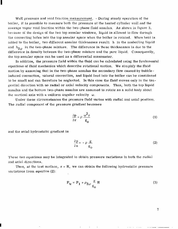
Wall pressure and void fraction measurement. - During steady operation of the boiIer, it is possible to measure both the pressure a t the heated cylinder wall and the average vapor void fraction within the two-phase fluid annulus. A s shown in figure 3 . because of the design of the two top annular windows, liquid is allowed to flow through the connecting holes into the top annular space when the boiler is rotated. When heat is added to the boiler, two different annular thicknesses result: h in the nonboiling liquid and h in the two-phase mixture. The difference in these thicknesses is due to the difference in density between the two-phase mixture and the pure liquid. Consequently, the top annular space can be used as a differential manometer.
equations of fluid mechanics which describe rotational motion. We simplify the fluid motion by assuming that in the two-phase annulus the secondary flow caused by bubble- induced convection, natural convection, and liquid feed into the boiler can be considered to be small and can therefore be neglected. In this case the fluid moves only in the tan- gential direction with no radial o r axial velocity components. annulus and the bottom two-phase annulus are assumed to rotate as a solid body about the vertical axis with a uniform angular velocity w.
The radial component of the pressure gradient becomes
2Q
In addition, the pressure field within the fluid can be calculated using the fundamental
Thus, both the top liquid
Under these circumstances the pressure field var ies with radial and axial position.
g0 ar
and the axial hydrostatic gradient is
These two equations may be integrated to obtain pressure variations in both the radial and axial directions.
Thus, a t the tes t surface, r = R, we can obtain the following hydrostatic pressure variations from equation ( 2 ) :
Pw = PI + p2@ H g0
(3)
7
. . . . . . . . .. . . . .

and
where p2 nulus and pl is the liquid density in the top, unheated annulus.
in the radial direction:
is the average effective density of the two-phase mixture in the bottom an- co
Similarly, equation (1) may b e integrated to obtain the following pressure variations
2 p 2 g 2 P 1- - P v +- ( R ~ - r l )
2g0
and
P I u2 pi = patm + - ( R ~ - ri2) 2g0
or since
r1 = R - hap
and
r i = R - h
then equations (5) and (6) may be written as
2 Pi = Patm + p2u - h (2R - h)
2g0
8

Determination of wall pressure: The local pressure a t the test surface wall may from equation (3) by using b e obtained by f i r s t eliminating the two-phase density p
equation (7). Therefore, 2(P
or
P = Pv + (P1 - Pv) W
Equations (4) and (8) are now successively substituted into equation (10) to get
2 1 (11) 2
- PJ + P , -H' g + pc h(2R -
Using this equation, the pressure at the test surface wall can be calculated, provided the pressures Pv and Patm are measured, the speed N (equal to 30 o/a) is measured, and the thicknesses h and h are measured.
two-phase annulus is defined as
2v Determination of average vapor void fraction: The average effective density in the
where
a average vapor void fraction
p, density of vapor
pL density of liquid in heated annulus
Note that, because the top annulus is unheated, the liquid temperature there is less than the saturation temperature in the heated annulus. annulus p
Hence, the liquid density in the top is not equal t o the liquid density in the heated annulus pL. I
9
The void fraction becomes
1 - 3 9 ? PL C Y =
PV
PL 1 - -
and (Y can be determined by solving for the two-phase density p by using equa- tions (4), (7), and (8) and substituting this resul t into equation (13). Equations (4) and (7) are set equal to one another to give
2(P
2 P ' + ~ & ~ ' = P ~ + ~ x h ( 2 R - h 2 &
2YJ 2g0
1 1 g0
Equation (8) is then used to eliminate Pi: 2 2
g p2qw h (2R - h2YJ) 'zw h(2R - h) + pL - H' = Pv + ___ 2 q
2g0 'atm + -
2g0 g0
Upon solving for p we obtain 2YJ'
The average vapor void fraction (Y can be calculated by using equations (13) and (16), provided the pressures Pv and Pat" the speed N, and the thicknesses h and h2co are measured.
Equation (16) may be put into a dimensionless form
10
r 1
P l 247 plw2h(2R - h) plw 2 h(2R - h)
1 2g0
and if we define
h - 247 5250 - R
and slightly rearrange equation (17) we get
OPERATIONAL PROCEDURES
Testing procedures and chronology will be presented in some detail because boiling heat transfer is known to be affected by many subtle conditions of the t e s t surface and fluid. Many t imes throughout the program the test surface was cleaned in an effort to control corrosion and pitting of the surface. A photograph showing some of this pitting is shown in figure 4. The surface was cleaned with cleansing powder using a cotton swab and water. cotton saturated with a degreasing agent.
and was allowed to f i l l with air when not operating. When two or more runs were made the same day, at least 1 hour elapsed between data points in successive runs. to taking experimental data (1) the water in the supply tank and feed lines was electric- ally heated to a temperature near 175' F (352 K), (2) the supply tank was pressurized to about 30 pounds per square inch (207 kN/m ) gage with nitrogen, (3) the boiler was rotated with no heat input, (4) the water supply valve was opened to allow water flow into
Then it was thoroughly rinsed with distilled water and wiped with
Except as noted later, the rotating boiler stood idle overnight pr ior to a test run
P r io r
2
11

the boiler, and (5) the power input to the boiler was gradually increased until boiling commenced. The system was operated under these conditions fo r about 30 minutes to degas the boiler surface. Upon shutdown the r eve r se sequence was followed.
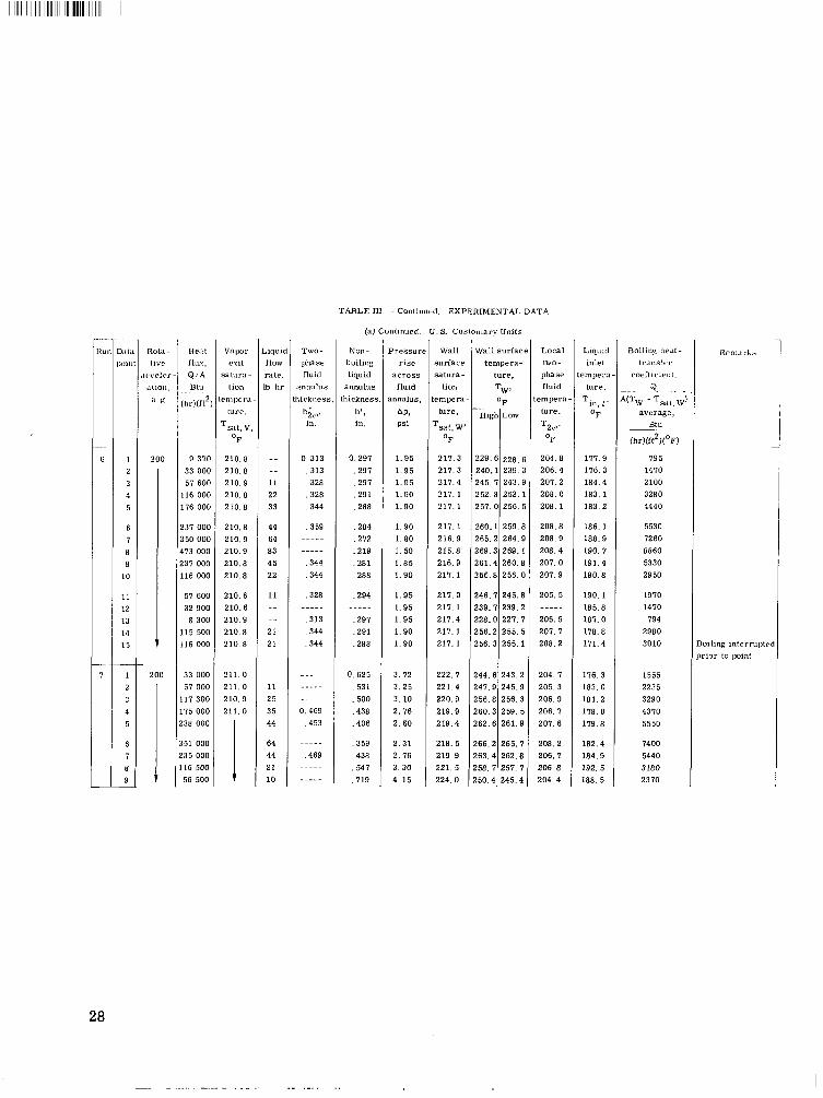
as outlined in table 11. The data obtained are presented in chronological order in table m. Operational procedures for each group of these tests are given in the subse- quent sections in the same order as listed in table II.
The rotating boiler was operated for 15 runs, which comprised six major groupings,
Rep roduci bil ity Tests
Runs 4, 5, and 6 (see table 111) were made to evaluate the repeatability of rotating boiler data. During run 4 at 25 g's and run 6 at 200 gcs, the speed of rotation was fixed and the power input was gradually increased f rom 500 to approximately 20 kilowatts, and then gradually decreased. P r i o r to run 4, the test surface was recleaned using the cleaning procedure described previously. In an effort to compare this recleaned test surface to a n "aged'? test surface, run 5 was made after the boiler had been operated during run 4 and after it had been standing for 1% hours. run 5 was identical to that of run 4.
1 The operational procedure of
Subcool ing
Runs 2 and 3 were made to study the effect of inlet water subcooling (saturation minus inlet temperature) on boiler operation at 25 and 200 g's, respectively. During these runs, the temperature at the inlet to the rotating boiler was regulated by electric- ally controlling the water temperature in the supply tank and feed lines. At each value of rotational speed and heat flux level, data were taken as the inlet temperature was raised from 143' to 189' F (335 to 360 K).
Fluid Level
Several runs were made to investigate the effect of fluid level on boiler heat t rans- fer. The thickness of the two-phase fluid annulus in the boiler was varied by adjusting the float-regulated needle valve a t the inlet to the boiler. A s described in reference 2, this rotating float valve generally maintained the fluid level constant over large var ia- tions in both rotational speed and heat f lux, although minor e r r a t i c variations did occur.
12
In run 7 (and a l so run 6) at 200 g's, the fluid level was arbitrari ly fixed, and the heat f lux was varied up to a maximum and then decreased. In runs 8, 9, and 10, the inlet water supply valve was closed after water was introduced and the fluid thickness reached approximately 0.75 inch (1.9 cm). With the power supply set at a fixed value, boiling occurred and the thickness of the two-phase fluid annulus decreased. Tempera- ture data were taken as the fluid level decreased. During run 8 at 200 g's and runs 9
, and 10 a t 25 g's data were recorded at four or five levels as the thickness decreased. This procedure was repeated fo r several settings of power input.
Fluid Temperature Profiles
In run 13, the thickness of the two-phase fluid annulus was kept constant and the radial position of the rotating thermocouple in the fluid annulus was varied. In run 14, the radial position of the thermocouple was held fixed while the thickness of the fluid annulus was varied.
cm) radially inward from the tes t surface after fixing its circumferential and axial positions. The boiler was then operated at 25 g's with a two-phase fluid thickness of approximately 0.41 inch (1.04 cm) and a total power input of 1. 50 kilowatts. When thermal equilibrium was reached, a thermocouple reading was made. The power input was then shut off and the boiler rotation was stopped so that the radial position of the thermocouple could be al tered without changing its circumferential or axial position. With a new radial position of the thermocouple, the procedure was repeated. Tempera- ture data were taken with the thermocouple set at 1/16 inch (1. 59 cm) intervals f rom 1/32 to 13/32 inch (0.079 to 1.03 cm) radially inward f rom the boiler surface. Data were obtained at speeds of 25 and 200 g's and at total power inputs of 1. 5 and 6.0 kilo- watts.
During run 14, the boiler was operated at 400 g's with the water inlet supply valve closed, and with the local fluid thermocouple held fixed at 1/4 inch (0.64 cm) from the test surface. The run started with a nonboiling liquid annulus thickness of 0.375 inch (0.952 cm) and a power input of 1. 5 kilowatts. During operation, as the water was evaporated away, the thickness of the two-phase f h i d annulus decreased. Temperature data were taken as the thickness of the top liquid annulus changed f rom 0.375 to 0.063 inch (0.952 to 0.159 cm). This procedure was repeated at a second power input level of 6. 0 kilowatts.
During run 13, the position of the local fluid thermocouple was set 1/32 inch (0. 079
13

Boi l ing Inc ip ience
Runs 11 and 12 were made a t low power inputs to obtain natural convection data and to observe the incipience of nucleate boiling for various rotative accelerations. During run 11 the speed of the boiler was successively fixed at 660, 940, 1330, 1880, and 2660 rpm (corresponding to 25, 50, 100, 200, and 400 g's a t the heating surface, respec- tively). At each speed setting the total power input was gradually increased in s teps of 150 watts from a n initial value of 150 watts up to approximately 600 watts, by which value nucleate boiling generally had commenced. was similar to run 11 except that the rotative acceleration was initially s e t a t 400 g's
and was successively decreased to 25 g's.
The operational procedure of run 12
Nucleate Bo i l ing
Two runs were made at inlet water subcoolings from approximately 20' to 55' F (11 to 30 K) to investigate the effects of acceleration on nucleate-boiling heat transfer. During run 1, the nominal power input was fixed at 500 watts, and the rotative accelera- tion was successively fixed at 15, 25, 50, 100, 200, and 400 g's. then increased, and the rotation was again varied in the s a m e order. This procedure was repeated fo r six power levels to 9 . 0 kilowatts. During this run, the two-phase fluid level in the boiler varied between 0. 188 and 0.656 inch (0.480 and 1.67 cm).
(0.95 cm). The nominal power input was fixed at 1 . 7 kilowatts, and the rotation was successively fixed at 50, 100, 200, and 400 g's. The power input was then increased, and the speeds were again varied in the same order. This procedure was repeated for eight power levels to 35 kilowatts. The boiler was then operated for several minutes a t 400 g's with a power input of 42 kilowatts. A short circuit occurred in the main electrical heater before full data could be obtained.
The power input was
Run 15 was made with a n approximately constant two-phase fluid level of 0.375. inch
RESULTS AND DISCUSSION
General
Performance characteristics. -. - - Visual observation of the boiling process showed that the boiler operated in a steady manner with a stable liquid-vapor interface. For example, a t 400 g's the boiler operated in a steady manner even a t a total power input of 42 kilowatts, which is a radial heat flux of 818 000 Btu per hour per square foot. This
14
~....-1.-.-,,- ,.,.. ,, ,, ..I ,111 I .,,, 111 I,,,. I , , I I, I I.- I 1,1111 111111.1.1111 I 11.- I

heat flux i s estimated to be twice the critical, o r "burnout" heat f l u s for atmospheric pool boiling of water a t normal gravities.
space pressure was always within 1 inch (2. 5 cm) of water of the ambient atmospheric pressure. For most of the runs (when the water supply valve was open), the boiler had an approximately constant inventory of liquid, but with a continuous throughflow whose rate depended on the power input. At low power inputs (low flows), the boiler inventory was large relative to the inflow, and pool boiling was simulated. On the other hand, a t high power inputs, throughflow w a s larger and secondary-flow cells developed i n the boiling annulus.
low and high accelerations f o r the s a m e heat flux. At low accelerations there were many active nucleation sites on the boiling surface, giving rise to many large s i ze bubbles in the boiling annulus. The fluid in the boiling annulus had a frothy appearance and the liquid-vapor interface of the annulus was quite irregular. irregular shape, the water in the top nonboiling annulus at all accelerations behaved as in solid body rotation, with a smooth mirror-l ike interface (see figure 5(a)). accelerations, the number of active sites was sharply reduced, and bubble s izes were smaller. annulus appeared as in figure 5(b). Normally the convection cells correlated in number and position with the liquid feed holes. The liquid-vapor interface was not as irregular a t high accelerations as a t low accelerations. acceleration and power input on the boiling action, showing photographs and providing a motion-picture film supplement (C -253) which is available on loan.
Void fraction. - From observations of the liquid level h' in the nonboiling upper annulus and the two-phase fluid thickness h' vapor void fraction cc in the two-phase boiling annulus can be calculated using equa- tions (13) and (16). This average void fraction is plotted as a function of acceleration in figure 6 fo r three levels of heat flux. of water a t 1 g and 1 atmosphere are also included.
Even though the uncertainty in these data is fairly large because of the difficulty in measuring the thickness of the two-phase fluid annulus, a definite trend can be observed. A s the acceleration increases at a fixed heating rate, the average void fraction decreases. This shows there are fewer vapor voids in the boiling fluid, presumably because there are fewer active nucleation s i t e s and also smaller s ize bubbles. with the resul ts of Graham and Hendricks (ref. 9), who showed that both the number of active s i tes and the maximum bubble departure diameter decrease with increasing a c - celeration. fraction increases with heat flux as expected.
The rotating boiler operated essentially a t atmospheric pressure; i t s esit vapor
Figure 5 is a sketch showing the typical visual appearance of the boiling annulus a t
In contrast to this
At high
Also, secondary -flow cells disrupted bubble nucleation, and the boiling
Reference 2 discusses the effects of
in the boiler (see. table 111), the average 2 v
Data from reference 8 for nucleate pool boiling
This trend agrees
It is also apparent in figure 6 that, a t any given rotative speed, the void
1 5
Reproducibility and Aging
Runs 4, 5, and 6 were made specifically to check for repeatability of the nucleate- boiling data, effects (if any) of surface cleaning procedure, and effects of progressively increasing the heat flux compared with decreasing i t (hysteresis). Within the data of these three runs, no consistent effects o r conclusions could be determined. plots of wall temperature against heat flux data of runs 4 and 5 a t 25 g T s fell within a scatter band width of A. 5' F (*O. 8 K). Run 6 (and also run 7) a t 200 g's was similar except fo r the data a t a heat f lux near 116 000 Btu per hour per square foot (365 000 W/m ), which indicated that wall temperatures during a decrease from high boiling heat fluxes a t high g's can be as much as 4' F (2 .2 K) hotter than comparable values during the initial startup from low heat-flux levels. and subsequent progressive flooding of smaller and smaller surface cavities (which slowly refill with a i r during down periods).
labelled "aging, " appeared. This trend is illustrated in figure 7 fo r increasing-heat- flux data taken a t 200 g's. heat flux normal to the test surface Q/A is plotted against the wall superheat
Tw - Tsat,w. from the saturation temperature curve fo r water fo r the p re s su re a t the wall Pw cal- culated from equation (11). Figure 7 shows that, as running t ime elapsed, the wall superheat increased for the same heating level. Fortunately, this increase was much slower in the second half of the program than it was a t first (between runs 1 and 6). Also, data taken during any one run or during consecutive runs are much less affected by this aging than would be indicated by the total spread of data in figure 7.
The cause of the surface aging effect could not b e pinpointed. It is assumed to be the combined effects of surface pitting, corroding and scaling, and possibly the progres- sive flooding of smaller and smaller cavities with liquid.
All the
2
This could be a manifestation of outgassing
In review of all the data runs, a significant and reasonably consistent trend, herein
Figure 7 is a typical boiling heat-transfer plot, in which the
The saturation temperature at the heated wall Tsat, is determined
In let Liquid Subcooling
The subcooling referred to here is the difference between the saturation tempera- ture a t the boiler wall and the temperature of the inlet liquid a t the feed holes,
Ts;it: w - Tin, I - ATsub. fixlire 8: wherein heat flux is plotted against wall superheat T,V - TsLit, w. t h a t inlet subcooling does not measurably affect the nucleate-boiling results. sult is consistent with subcooled, forced flow, fu l ly developed boiling data of refer - c'ncc 10: taken wi th water a t 1 g and low pressures . It is concluclecl, thc>reforc, t h a t
- The effect of inlet subcooling a t 25 and 200 g 's is shown in It is evitlcnt
This re-

iiilct sub cool in^, even a t high accelerations, is not important in studying nucleate- Imiling data of Q;A as a function of Tw ence 2 should be applicable in this respect, even though inlet subcoolins was not in- clepencle 11 t ly regulated.
Consequently, the data of refer- - Tsat, w e
F lu id Level
The effect of five different levels of fluid in the boiling annulus (measured in the top nonboiling annulus), with no inlet feed supply, is shown in figure 9 for both 200 and 25 6's. A s the thickness of the fluid annulus increases (with a corresponding increase in pressure at the heated wall), the wall superheat decreases. This decrease, a t a given heat flux, is a n increase in boiling heat-transfer coefficient (presented in table 111) and is in agreement with the well-known pressure effect in pool boiling (ref. 11). Whether o r not other effects are present, such as increased convection velocities with increased fluid thicknesses, cannot be determined from the data.
F lu id Temperature Profi les
In reference 2, temperatures in the two-phase rotating annulus were measured a t On the basis only one point, 1/8 inch (0.32 cm) radially inward from the heated wall.
of this limited amount of data, fluid temperature '?inversions" were postulated to exist i n the boiling annulus (fig. 17 of ref. 2). temperature was measured at several distances f rom the wall along a radial line i n the horizontal midplane of the boiler, as shown in figure 10.
heat fluxes near 27 000 and 115 000 Btu per hour per square foot (85 000 and 362 000 W/m ) a t accelerations of 25 and 200 g's. It is evident that a distinct temperature inver- sion es i s t s inward from the heated thermal sublayer. temperature is generally less than the saturation temperature in the vapor (and of course l e s s than the calculated local saturation temperature in the fluid, Tsat, f ) . Furthermore, the degree of local subcooling appears to increase with an increase in acceleration. This local subcooling is also evident in figure 12, which shows the local fluid tempera- ture measured a t a constant position 1/4 inch (0. 64 cni) from the test surface for the t ~ v o heat f l u e s and 400 g's during run 14, in which the water feed supply was valved off. Note tha t , when the thermocouple is within the fluid annulus, the temperature reads considcrably l e s s than vapor saturation (as much as 9. 6' F (5. 3 K) less ) , and ivhcm I I I O
liquid-vxpor interface passes over the thermocouple, leaving i t in the va1)or s l ~ a c ' c ~ .
In the present investigation, the local fluid
The two-phase fluid temperatures, obtained in run 13, are shown in figure 11 for
2
Also i t appears that the fluid bulk
l1llllll111l111l1l I I1 I l l II I1
readings near the saturation temperature a r e obtained. interface is estimated to be 1/32 inch (0. 08 cm) radially inward from the measured nonboiling liquid interface in the top annulus. )
The results presented in figures 11 and 12 may appear contrary to the rule that during bulk boiling, with net evaporation, the average fluid bulk temperature must be slishtly superheated. This apparent contradiction may be explained when it is realized that the local fluid thermocouple measured the radial temperature profile a t only one circumferential and axial position. presentative of the whole boiling annulus, as will be discussed next.
boiler through feed holes a t the outer radius at the bottom of the test surface. colder, denser liquid is centrifuged radially outward and flows both circumf erentially and axially upward to form an annulus of colder liquid just inward from the heated thermal sublayer on the wall. However, this annulus is observed to be broken up by the bubbles leaving the surface, and convective secondary-flow cells are formed in the horizontal plane, as mentioned earlier and shown at the top of figure 10. It is possible that the local fluid thermocouple measured radial temperature profiles mainly in the cooler outward-bound leg of a convective cell, as illustrated. Superimposed on this flow, in a vertical plane through the axis, a tertiary-flow cell, o r "smoke-ring" torous, is postulated, as shown at the bottom of figure 10. complex swirling flow in the boiler; probing this fluid annulus to obtain an accurate average bulk temperature would be very difficult.
cooled, as figures 11 and 12 would indicate. the secondary cells travelled circumferentially around the boiler and past the feed holes. average fluid temperature 4/32 inch (0.32 cm) radially inward from the heated surface; this temperature was subcooled 4.8' F (2.7 K) below the vapor temperature Tsat, v. In any case, the conventional fluid bulk temperature is not obtainable from these data. Instead, the calculated saturation temperature a t the wall TSat, is used herein to present the heat-transfer data.
(For run 14, the liquid -vapor
This radial profile position may not have been re-
Referring again to figure 10, during the boiling process subcooled water en te r s the This
The resultant of these motions is a
It is also possible that the volume-averaged fluid bulk temperature is in fact sub- At least once, in run 15, data point 24,
In this case the local fluid thermocouple must have measured the circumferential-
Natural -Convection to Nucleate-Boil ing Incipience
The effect of acceleration on natural convection and incipient boiling is shown in figure 13 using the data of runs 11 and 12. The incipient boiling point is defined as t h a t heat f l u a t which bubble formation is f i r s t observed. 1-1111 11 n.ere taken for increasing speed while the data of r u n 12 were taken for derreas-
A s noted ear l ie r , the c l a t a of
18
ing speed. approximately the same. The agreement between the data presented in runs 11 and 12 is good. creases for a given temperature difference, as expected. In addition, the incipient boiling data confirm the resul ts of Graham and Hendricks (ref. 9) that, as ' the accelera- tion increases, both heat flux and wall superheat increase a t incipient boiling.
Figure 14 shows the natural-convection data a t o r near boiling incipience plotted conventionally as Nusselt number Nu as a function of the product of Grashof number G r and Prandtl number Pr. The correlation of Fishenden and Saunders (ref. 12) for natural convection from a horizontal plate is given f o r comparison, even though a large uncertainty in the experimental data exists in this low heat flux region, and the teni- perature difference in the Grashof and Nusselt numbers involves Tw - than Tw - Tbuk, as discussed earlier.
The test surface was precleaned prior to each run, and the fluid levels were
Note that in each case, as the gravity level increases, the heat transfer in-
rather Tsat, w
Nucleate Boiling
Because of the surface aging factors previously discussed, and the fact that the fluid level was not maintained constant during run 1, the nucleate-boiling data of run 15 are considered superior to those of run 1. against wall superheat Tw - Tsat, In the low-heat-flux boiling region (where natural convection is important), the boiling coefficient increases markedly as acceleration increases; values of this coefficient (ratio of ordinate to abscissa) are given in table III. The coefficient increases as much as 60 percent f rom 50 to 400 g's.
verge into a narrow band of wall superheat values (+2O F; +1 K), with the higher accel- erations converging a t progressively higher heat fluxes. superheats a t high heat fluxes, a slight trend is evident for a reversal of the effect of acceleration compared with that at low heat fluxes. "cross-over" region, has been reported and discussed before (refs. 2 to 7), and in view of the present data with their more accurate wall saturation pressures, is still debatable. viously available nucleate-boiling data a t high accelerations. selected data a t high accelerations from the present report and from reference 2, coni- pared with the band of data given in reference 4. The NASA data (herein and ref. 2) fall along the center of this band and extend to much higher heat fluxes and accelerations. Thus, the iiiajor effects of acceleration on nucleate boiling are portrayed in fisure 16,
In figure 15, heat flux from run 15 is plotted fo r accelerations of 50, 100, 200, and 400 g's.
At the higher heat fluxes the heat-transfer curves fo r the various accelerations con-
Within the.narrow band of wall
Such a reversal , with i t s necessary
Adelberg and Schwartz (ref. 4) conclude similarly, after analyzing the pre- Shown in figure 16 are
19
I
Ill11 I I
xiid ; m y "rcvcrsal" a t high heat fluxes is as small i n magnitude as the usual scatter in esiw r i ni cntal c i a ta .
SUMMARY OF RESULTS
Using an axisynimetric rotating boiler with a n electrically heated cylindrical wall and continuous throughflow of water as test fluid, the following principal resul ts were ob - tai ned :
1. Stable nucleate-boiling heat -transfer data a t atmospheric pressure w e r e obtained a t radial accelerations up to 400 g's and a t heat fluxes up to 818 009 Btu per hour per square foot (2. 58 MW/m ).
2. The following effects of acceleration were observed in the data as rotative a c - celerations increased:
2
a. Boiling-heat-transfer coefficients increased a t low heat fluxes (as much as 60 percent in going f rom 50 to 400 g's) ; at very high heat fluxes the coefficients were practically independent of acceleration.
b. Bubble nucleation and average vapor void fractions in the boiling annulus decreased, a t constant heating levels.
fluid annulus into alternating zones of bubbly and relatively clear liquid.
local temperature inversions below saturated vapor temperature (as much as 9.6' F or 5. 3 K).
e. Natural-convection to nucleate-boiling incipiency occurred a t progressively higher heat fluxes and higher wall superheats. 3. Inlet water subcooling had no measurable effect on boiling heat transfer, but i n -
c. Convective secondary -flow cells increased in vigor and separated the boiling
d. Fluid temperature profiles developed steeper radial gradients, with increased
creases in fluid thickness in the boiling annulus increased the boiling heat-transfer coefficients (especially at high acceleration and low heat f lux) .
4. The heat-transfer surface "aged" during the elapsed time of the runs , requiring gradually increased wall superheats for a given heat flux; this effect diminished with tin1 e.
Lewis Research Center, National Aeronautics and Space Administration,
Cleveland, Ohio, January 6, 1971, 120 -2 7.
20
~. . . . ..
A
a/%
1) C
D
Gr
6
lT -0
H
H'
I1
h '
"NC
APPENDIX -
2 2 area, f t ; ni
ratio of rotational a c c el era - tioii to acceleration of gravity
specific heat of liquid, Btu/ (Ibm)(OF); (W)(sec)/(g)(K)
characteristic dimension in natural convection correla- tion equal to fi, f t ; m
Grashof number. ' 3 2
P(Tw - Tsat, w )g D / v acceleration due to gravity,
2 2 32.2 ft/sec ; 9 .8 m/sec
32.2 ft-lbm/(lbf)(sec2); 1 m-Kg/(N)(sec ) 2
one-half of vertical height of boiler, ft; m
vertical distance from top of boiler wall to midpoint of top unheated annulus, f t ; m
thickness of top nonboiling liquid annulus, ft; m
thickness of top nonboiling liquid annulus, in. ; cm
natural -convection heat - transfer coefficient, Btu/ (hr)(ft ) ( F); W/(m2)(K)
annulus, ft; 111
2 0
thickness of two-phase fluid
thickness of two -phase fluid aniiulus, in; cni
SYMBOLS
k the r m a1 c ondu c t ivi t y of 1 iqu i d ~
B tu/(hr)(f t) (OF); W/( m)(K)
N rota t io na 1 speed of bo i 1 e r , r pin
Nu Nusselt number, tiNC Djk
P
AP pressure rise ac ross two-
pressure, lbf/ft 2 abs; N/m 2
phase fluid annulus, lbf/in. ; N'm
atmospheric pre s su r e, lbf/ft2 abs; N/m2
2 2
'atm
pressure in vapor space, pV 2 2 lbf/ft abs; N/m
pressure a t midpoint of pW
heated surface; lbf/ft 2 abs; 2 N/m
p res su re a t top of heated surface, lbf/ft abs; N /m2
2 p1
pressure a t midpoint of top 2 unheated surface, lbf/ft
abs; N/m
pi 2
Pr Prandtl number, p c Jk
W A
R radius of heated wall, ft; ni
r radial position, ft; 111
1 2 2 heat flux, Btu/(hr)(ft ); W/m
radius of interface of two- phase annulus, ft; ni
radius of interface of top liquid annulus, f t ; ni
'1
1- i 0 T temperature, F; K
2 1

Tbulk
Tin, 1
T1
sa t ,a tm
Ts"t, f
Tsat, v
Tsat, w
ATsub
TW
bulk temperature of liquid, F; K 0
temperature of inlet liquid, E'; K 0
temperature of nonboiling liquid annulus, F; K
saturation temperature at atmospheric pressure ,
0
F; K 0
saturation temperature i n fluid annulus, F; K
saturation temperature in
0
0 vapor space, F; K
volume coefficient of expan- 13 O F - l - K-l sion, 9
absolute viscosity of liquid, lbm/(ft)(hr); kg/( m)( sec)
P
V kinematic viscosity of liquid,
5 dimensionless ratio, h/R
2Q 3
f t 2 /sec; m 2 /sec
dimensionless ratio, 11 /R (2 cp P density, lbm/ft3; kg/m
density of liquid in heated annulus, lbm/ft ; kg/m3
PL
PI saturation temperature at boiler wall, OF; K
liquid inlet sub cooling,
Tsat, w - Tin, 1 , O F ; K PV
pw boiler wall surface tempera-
0 ture, F; K
vertical position, f t ; m
average void fraction in boiling fluid
w
density of liquid in top unheat- ed annulus, lbm/ft 3 ;
k / m 3
k / m 3
fluid annulus, lbm/€t 3 ;
k / m 3
density of vapor, lbm/ft3;
effective density in two-phase
angular velocity of boiler, rad/sec
22

REFER EN CES
1. Gray, Vernon H. : Feasibility Study of a Rotating Boiler fo r High-Performance Rankine Cycle Power Generation Systems. Advances in Energy Conversion ,En- gineering. ASME, 1967, pp. 145-149.
2. Gray, Vernon H. ; Marto, Paul J. ; and Joslyn, Allan W. : Boiling Heat Transfer Coefficients, Interface Behavior, and Vapor Quality in a Rotating Boiler Operating to 475 G's. NASA.TN D-4136, 1968.
3. Merte, Herman, Jr. ; and Clark, J. A. : Pool Boiling in an Accelerating System. J. Heat Transfer, vol. 83, no. 3, Aug. 1961, pp. 233-242.
4. Adelberg, Marvin; and Schwartz, S . H. : Nucleate Pool Boiling at High G Levels. Chem. Eng. Progr. Symp. Ser., vol. 64, no. 82, 1968, pp. 3-11.
5. Costello, C. P. ; and Tuthill, W. E. : Effects of Acceleration on Nucleate Pool Boiling. Chem. Eng. Prog. Symp. Ser . , vol. 57, no. 32, 1961, pp. 189-196.
6. Turton, J. S. : The Effects of P r e s s u r e and Acceleration on the Pool Boiling of Water and Arcton 11. Int. J. Heat Mass Transfer, vol. 11, no. 9, Sept. 1968, pp. 1295-1310.
7. Eschweiler, J a m e s C. ; Benton, Allan M. ; and Preckshot, George W. : Boiling and Convective Heat Transfer at High Accelerations. Chem. Erg. Prog. Symp. Ser. , vol. 63, no. 79, 1967, pp. 66-72.
8. Iida, Yoshihiro; and Kobayasi, Kiyosi: Distributions of Void Fraction above a Horizontal Heating Surface in Pool Boiling. JSME Bull. , vol. 12, no. 50, Apr. 1969, pp. 283-290.
9. Graham, Robert W. ; and Hendricks, Robert C. : A Study of the Effect of Multi-G Accelerations on Nucleate-Boiling Ebullition. NASA T N D-1196, 1963.
10. Jeglic, Frank A. ; Stone, James R. ; and Gray, Vernon H. : Experimental Study of Subcooled Nucleate Boiling of Water Flowing in 1/4-Inch-Diameter Tubes at Low Pres su res . NASA TN D-2626, 1965.
11. McAdams, William H. : Heat Transmission. Second ed. , McGraw-Hill Book Co. , Inc., 1942.
12. Fishenden, M. ; and Saunders, 0. A. : An Introduction to Heat Transfer. Clarendon Press, Oxford, 1950.
23

IIIIII I
Two-phase fluid
/
-O.OOl*O. 005
TABLE I. - THERMOCOUPLE CALIBRATION DATA
(*O. 026 mV = 21' F (0. 56 K) a t 220' F (378 K). )
1880 rpni 2660 rpni I I 660 rpm 940 rpm location
Average deviationa, mV ~
-0.013-tO. 006
-0. 01450. 008
0.040+0.022
-0.03*0.04
0.013*0.005
~~
-0.025+0. 012
-0.013;tO. 003
0.037;tO. 018
-0.07iO. 06
0.013+0.003
-0.011*0. OOE
-0. 015*0. 007
0.027*0.015
-0.09*0.06
0.013*0.002
-0.015+0.005
-0.015+0.007
0.029*0.012
-0.11*0. 07
0.013*0. 002
-0. 013+0. 003
-0. 012-tO. 005
0.031-tO. 015
-0.17*0.01
0.012*0.002
"Thermocouple reading minus saturation temperature based on p r e s s u r e in vapor. "This thermocouple output w a s more e r r a t i c than other thermocouple outputs because lower sliprings
were not as accura te as top sliprings, and momentary readings could not b e taken.
24
... . . . . . . I I., I

TABLE 11. - G R O U P I N G OF E X P E R I M E N T A L R U N S
Group
I c p r o d u - . i b i l i t y
; u l x u u l i n g
2 lu id l e v e l
Tluid
e 111 lie ratu 1.1 i r o f i l e s
3011 i n p
n c i ] , i e n c e
\ luCle.l tc
> o i l i n g
h r o n o -
o g i c a l
r u n
umber
4
a
6
2
3
a7
"8
9
"10
1 3
"14
11
"12
1
1 5
O p e r a t i n g m o d e
4t 2 5 g's. v a r y h e a t f l u x t o
i n n x i m u m . t h e n d e c r e a s e i t .
At 2 5 a's: v a r y h e a t f l u x t o
1 m a x i m u m , t h e n d e c r e a s e i t .
4 t 2 0 0 6's. v a r y h e a t f l u x t o
I m a x i m u m . t h e n d e c r e a s e i t .
At 25 g's a n d at f i x e d h e a t
l l i i xes . v a r y l i q u i d i n l e t
l e n i pr r a t u r e .
At 200 g ' s a n d at f i x e d h e a t
I l u x c s . v a r y l i q u i d i n l e t
ten1 pe ra tu r e .
At 200 g's a n d f i x e d f l u i d
l e v e l . v a r y h e a t f l u x .
At 200 ~ ' s a n d f i s e d hc.;rl
f l u x e s . t a k e d a t a wi th w a t e r
s u p p l y v a l v e c l o s c d .
At 2 5 g's and fixed h e a t
f l u x e s . Like d a t a w i t h w a t e r
s u p p l y v a l v e c l o s e d .
At 2 5 g's a n d f i x e d h e a t f l u x e s .
t a k e dnta w i t h w a t e r s u p p l y
v a l v e c l o s e d .
For 2 5 and 2 0 0 g's a t f i x e d
h e a t f l u x e s . v a r y p o s i t i o n of f l u i d a n n u l u s t h e r m o c o u p l e .
At 400 6's. f i x e d h e a t f l u , and no i n l e t f e e d . r e a d f l u i d
a n n u l u s t h e r m o c o u p l e .
At f i x e d s p e e d s ( i n c r e a s i n g )
v a r y p o w e r i n p u t f r o m 1 5 0
to 600 W.
At f i x e d s p e e d s ( d e c r e a s i n g ) ,
v a r y p o w e r inliut f r o m 1 5 0
to 600 W.
At f i x e d h e a t f l u x e s ( i n c r e a s -
i q ) , v a r y s p e e d f r o m 15 t o
400 S'S.
A t f i x e d h e a t f l u x e s ( i n c r e a s -
i n g ) . v a r y s p e e d f r o m 50 t o
4 0 0 g's.
r e s t s u r f a c e
p r e p a r a t i o n
P r eclea n e d
and p r e -
>Oiled
P r e b o i l e d ,
not p r e -
c l e a n e d
P r e b o i l e d .
not p r e -
c l e a n e d
Not p r e -
c l e a n e d . n o t
p r e b o i l e d
Not yrr- r l l m c d . not
p r e l i u i l e d
P w b o i l e d .
not l i r e -
clIc:lned
N u h i i i g t ~ s
1 I . l l I l l r u l l 7
N o c.h.uig:rs
IIYJIN rui i 8
P r e c l e a n &
a n d p r e -
b o i l e d
N o c h a n g e s
from r u n 12
N o c h a n g e s
f r o m r u n 1 3
P r e c l e a n e d
a n d p r e -
b o i l e d
P r e c l e a n e d
a n d p r e -
b o i l e d
P r e r l e a n e d ,
n o t p r e -
b o i l e d
P r e c l e a n e d
a n d p r e -
b o i l e d
R u n
= r a t i n g
t i m e .
h r
1 . 0
1.0
1. 5
4 . 0
4 . n
1 . 0
1.0
2 . 0
2 . 0
2 . 5
1 . 5
3 . 5
3 . 0
9 .0
5. 5
i m u l a t i v e
p e r a t i n g
t i m e ,
h r
18.0
1 9 . 0
20. 5
.-
1 3 . 0
1 7 . 0
2 1 . 5
2 2 . 5
2 4 . 5
26 . 5
3 5 . 5
3 7 . 0
30 . 0
3 3 . n
9 .0
4 2 . 5
' l ~ p e r a t e d s a m e d a y as p r e c e d i n g r u n .
25

I !I 111 I1 1111 lllllll111ll1l11lIIl I I I I
Run Ddla iwinl
_ _ 1 2
3 4 5 7 8
9 10 11 12 13 14
15 16 17 18 19 20
21 22 23 24 25 26
27 28 29 30 31 32
2 1
Hcal flus.
- q , A , Blu
(l,r)(f12)
10 150 10 150 10 000 9 780 9 480 9 100
33 600 33 600 33 400 33 200 32 900 32 500
57 000
56 400
57 000 56 800 56 700
56 000
15 25 50
100 200 400
15 25 50
100 200 400
15 25 50
100 200 400
Vapor Liquid exit flow
sa1ur:i- rate, lion Ib h r
lrnl~ler - I
lure.
Tsa1, v, OF
210 .7 ---- ...-
..__ I - - - -
..._
210.4 - - - -
210 .7 - - - - ..._
__._
..._
..._ I .___
210.7 1 0 . 5
210.6 210.6
Liquid inlrt
1,’11111,.1’.1 - LUI.1..
OF
169 .3 169.8 170. 5 172. 6 176.6 184 5
169 .3 171.9 174.2 175.6 179 .4 188 .2
169 .0 170.8 172 6 17fi. 4 178.8 185.2
167.9
’
25
-
25
LO?.ll 1W” -
]Ih.lSt.
r h i d l e m 111’r.t
1 “ W .
TZd, OF
209. 1 208.4 206.4 206.2 203.8 199.9
209. 1 209. 1 208 .5 207.4 205.9 200 .0
209. 1 209. 1 209 1 207.9 205. E 203. 7
209 .4
33 ti00
I 1
68 800
0.188
250 .313 .344 , 3 5 0 .438
, 3 4 4 .438 ,469 . 516 ,469 , 4 0 6
.406 , 4 0 6 . 531 . 531 . 506 , 4 6 9
210. i 210.7 210 i 210.6
210. 5 210.6 210 .5 210 .5
0,063 . 188 , 2 5 0 , 3 1 3 ,328 .406
,219 , 3 4 4 ,406 .469 .438 , 3 7 5
, 2 5 0 .219? .438 ,469 ,484 , 4 5 3
21 15 25 50
100 200 400
1 5
200 ,ii 400
25 25 25
31
115 GOO 210.6 115600 115 500 115 300 115 100 114 700
176 000 210.6
I I 1
I O 150 210 .7 IO 150 2 1 0 . i 10 150 210 i
13
Two- No11- I h s r boiliBy fluid liquid
annulus annulus
t h i c h e s s . lh i ckwss
, 4 8 4 ,438 . 500 . 563 , 531 ,438
. 594 ,594 .625 , 6 5 6 , 6 2 5
53 1
0 .250 , 2 5 0 2 50
.2n I
I 28 1
, 2 8 1 .344 .438 . 500 . 500 , 4 0 6
,438 , 5 0 0 . 563 . 594
594 . 500
0 188 188
I R H
181
. 181 ,188 ,181
163 172 172 172
Prrssur r i s e
:1cI’oss fluid
annulus, All. psi
0. 06 .20 . 4 5
1 .02 2.10 5 .20
. 1 5
. 3 0
. 6 5 1.47 2. 76 4 .80
. 16
.22
. 7 0 1 .47 3. 0 5 . 7
. 18
. 3 1
. I O 1. 55 3 . 1 5 .2
. 2 3
. 4 1 .86
1 80 3. GO 6. 20
0 . 2 0 . 2 0 . 2 0
. 2 0
I 19
w;III surfarc sa 11, r.1 -
lion 1 Pl l l pt. L‘il
lure.
TSZll. w 0
210 .9 211.4 212 .3 214 .2 217.7 226.6
211.2 211 .7 213 .0 215 .7 219 .7 225 .7
211.3 211 .5 213 .3 215 .7 220.3 228.2
211 .3 211.6 213 .2 215 .8 220 .6 226 .8
211.4 212 .0 213.6 216.6 222.1 229.4
211.4 211 .4 211 .4
211.4 211.4 2 1 1 . 4 211 .3
211 .1 211.2 211.1 211.1
226.4 226 .7 227 .7 227.8 229. 5 234.2
231.4 232. 1
233 .7 235 .2 237 .7 241.8
235 .3 236 6 238 3 239 9 243. 1 248 .9
239. 1 240. 1 242. 5 243 6 248. 0 253 0
242 .2 243.2 245. 1 247. 1 251 7 259. 1
230.4 229.8 229. 5
235.0 235.0 235.3 235 .5
238.2 238.3 238.5 238.7
.....
...._
.....
654 1 662 650 718 8 02
1195
1665 1645 1615 1700 1830 2020
2370 2270 2270 2340 2410 2710
4160 4050 3940 4150 4210 4380
5720 5640 5590 5770 5840 5930
535 552 Sl i I
1425 1 4 2 5 1405 13y0
2540
2540 2510 24')0
26

TABLE III. - Continued. EXPERIMENTAL DATA
(a) Continued. U. S. Customary U n i t s
lati oin
1 2 3 4
5 6 I 8
9 10 11 12
13 14 1 5
1 2 3 4 5 6
I 8 9
10 11 12
13 14 1 5 16 11
18 19 20 21
Heat flux,
Q/A Btu
ir)(ft2
9 500
i 1 1
32 900
68 IO0
1 5 200 15 200 1 5 200
10 200 33 600 5 1 200 16 000 1 6 000 33 000
55 000 74 000 18 000 60 000 34 000 10 200
10 200 34 000 70 000 $1 000 10 000
IO 000 30 000 33 500 13 600
Vapor ex i t
s a t u r a - t ion
empera ture ,
sat,^, OF
210. I
I 210. I 210. I 210. I 210.6
210. I 210. I 210.6 2 1 0 . 6
210 .6 210 .6 210.6
210.8
1 210 9
210 .9 2 1 0 . 9 210 .8 210 .9 2 1 0 . 9 210 .9
210 .9
1 210.8
I
iqui, flow .ate, S/hr
_ _ _. ..
..
._
._
._
..
12
I 21 2 1 21
_ _ _ _ 10 22 33 43
64 33 23 11 ..
..
.-
_.
13 26 39
55 33 18 ..
Two- phase fluid
annulus i ickness
h2VJ in.
0 .344 , 3 4 4 , 3 4 4
, 3 4 4
1 1
, 3 5 9
, 3 5 9 ,359 3 59
0.438 .28 1 , 3 1 3
1 1 28 1
0 .266 , 2 8 1 .281 . 2 8 1 , 2 9 1
.313 , 3 1 3 , 2 9 1 .313
Non- boiling l iquid
annulus i ickness ,
h' , in.
0 . 3 3 1 , 3 3 1 , 3 3 4
Wall ;u r face catura-
t ion , m p e r a - l u r e ,
sat, w' 0
211.8
I 211. I 211. I 211. I 211.6
211. I 217. I 217 6 211 .6
211 .6 217.6 211.6
211 .8 211.4
I 211.5
211 .5 211 .5 211.4 211 .5 2 1 1 . 5 2 1 1 . 5
211 .5
1 211.4
1
Wall surface 'mpera
ture ,
TW' O F
227 .8 228.0 228 .2 228 .4
231.6 231 .8 238 .0 231 .3
244. I 244. 5 2 4 4 . 5 244.3
249 .8 249 .9 249 .9
229 .3 231 .9 239 .8 243 .0 246.6 249 .8
2 5 5 . 5 248 .9 243.0 238 .5 236 .3 230. 5
229 .6 236 .9 240 .9 245.9 250 .2
254 .6 241. I 242.3 236 .8
Loca l hV0-
phase fluid , m p e r a - tu re ,
TZV' OF
206.2 206.2 206 .5 206.1
2 0 1 . 5 201 .3 207.2 207 .2
208 .0 208.0 208 .0 208 .3
207.3 208. I 208.2
208 .2 208 .4 208. I 209.4 209 .9 210 .2
210. I 210.2 210 .0 209.5 208 .8 207 .5
201 .4 208.8 209 .2 209. I 209.9
210.2 209. I 209.5 208.2
Liquid inlet
mpera lure ,
Tin, 1' O F
165.1 114 .9 178.4 186.4
163. I 161.5 1 1 0 . 6 1 1 9 . 6
158 .9 166.4 114.0 182.4
1 6 5 . 0 i i a . 4 189.0
1 5 0 . 6 1 6 3 . 0 164 .8 1 6 3 . 5 165 .2 1 6 9 . 3
112.4 114. 5 114 .8 115 .4 116 .1 117 .2
182 .8 180.0 116 .5 112.9 172 .8
114.4 116 .2 116 .8 118.4
Boiling heat- t r a n s f e r
coefficient,
Q -I
Tsa t , W) B k
(hr)(ft2N0F)
950 932 915 891
1655 1640 1625 1610
2550 2565 2555 2510
3580 3510 3510
583 1265 2015 3695 5000 6080
8060 4650 3130 2220 1310
531
563 1340 2380 4100 5410
6950 4960 3025 1320
27
I Ill! IllIlIlIlIlIIlIl 1111ll1l1111llllIIlI I I I1
High
229.6 240.1 245 .1 252 .8 257 .0
260.1 265.2 269.3 261.4 256.8
246 .7 239.7 228.0 256.2 256 .3
244.6 247.9 256.8 260.3 262.6
266.2 263.4 258. 7 250.4
TABLE 111. - Conlinucd. EXPERIMENTAL DATA
(a) Continued. U. S. Cuslomarv Unils
O F
Low
228 .6 239 .3 243.9 252. 1 256. 5
259.8 264.9 269.1 260 .8 256 .0
245 .8 239.2 221. I 255. 5 255 .1
243 .2 245.9 256 .3 259. 5 261 .9
265. I 262 .8 257. 7 245.4
28
1.II.l
)01n
1 2 3 4 5
6 7 8 9
10
11 12 13 14 15
- 1 2 3 4 5
6 7 8 9 -
Hedt flux, Q / A Blu
,r)(it2
9 370 33 000 57 600 16 000 76 000
37 000 50 000 73 000 3 1 000 16 000
i7 600 32 900 8 300
15 500 16 000
13 000 i7 000 17 300 15 000 18 000
i l 000 15 000 6 500
16 500
, i q u flow rate. lb hr
..
..
11 22 33
44 64 8 3 4 5 22
11 ..
._
21 21
..
11 25 3 5 44
64 44 2 1 10
Two- phase fluid
annulus hirkness
'16 '0 * in.
0 .313 , 3 1 3 ,328 ,328 -344
,359
, 3 4 4 ,344
,328
,313 344
,344
.._..
0.469 .453
,469
N o w boiling liquid
annulus hicknes!
h', in.
0 .297 .297 , 2 9 1 , 2 9 1 ,288
.284
.212
.219 , 2 8 1 ,288
,294
,297 291
.288
0 .625 53 1
. 500 ,438 - 4 0 6
, 359 ,438 . 541 . I 1 9
Pressur , r i s e
a c r o s s fluid
innulus,
*P? psi
1 .95 1 . 9 5 1 . 9 5 1 .90 1.90
1 . 9 0 1 . 8 0 1. 50 1 . 8 5 1 .90
1 .95 1 .95 1 . 9 5 1 . 9 0 1 . 9 0
3.72 3. 25 3 . 1 0 2. 76 2 . 6 0
2 .31 2 . 7 6 3. 30 4 . 1 5
- . . . . . . _ _ - . . .. . . - . -. . . .
Wall surface satura-
tion empera ture,
rsat , W' OF
217.3 211 .3 217.4 217 .1 217 .1
217.1 216.9 215 .8 216 .9 217 .1
217.0 217.1 217.4 217 .1 217 .1
222 .7 221.4 220 .9 219 .9 219.4
218.5 219.9 221 .5 224 .0
Local hvo- phase fluid
empera ture.
T2@. OF
204.8 206 .4 207 .2 208 .0 208 .1
208 .8 208 .9 208 .4 207 .0 207 .9
205 .5
205. 5 207 .7 208 .2
204. 7 205 .3 206 .9 206. 7 207 .6
208 .2 206. I 206.8 204.4
Llquld inlet
?nipern lure.
In, 1 ' OF
T .
171 .9 176 .3 184 .4 183 .1 183.2
186 .1 188 .9 190. 7 191.4 190 .8
190 .1 185.8 187.0 178 .8 171 .4
176 .3 183.0 181 .2 178 .0 179.8
182.4 184 .9 192 .5 188 .5
average, dt u
(hr)(ft2)('F)
79 5 1470 2100 3280 4440
5530 7260 8860 5330 2950
1970 1470 794
2980 3010
~~~~
1555 2235 3290 4310 5550
7400 5440 3180 2370
oiling interruple rior lo JMinl

. .- . .. . . - -- . .
Wall jurface a t u r a -
tion ?nipera -
TABLE 111. - Continued. EXPERIMENTAL DATA
(a) Continued. U. S. Custon~arg Uni t s
Wall surface tempera-
lure,
TW' OF
)a I ioi
1 2 3
4 5 6 I 8 9
i a 11
12 13
14 15 16 11
1 2 3 4 5
6 I 8 9
10
11 12 13 14
1 5 16 17 18 19
20 21 22 23 24
25 26 27 28 29
RoLi- l ive
ccclcr-
Heal ilux, Q A
200 I 33 3 3 Oo0 000 200 33 000
200 56 IO0
240.3 238 .8
249 .6 249.2 248.4 241 .3 248 .2
200 I 8 6 000
239. 1 205.8 204.0 238.4 205.4 204.3
241 .2 205 .8 203 .8 241 .2 206.0 203.1 247.1 206. 1 204.6 246. 5 2 0 1 . 0 206.0 241. 5 201. I 206.8
_..__
220.8 218 .1 216.4 215.2
25 I IO 150
..___ _..__ ...__ ...__
254 6 253.8 206.2 - - - - - 253.6 253.4 - - - - - - - - - - 2 5 2 . 6 252 .0 201 .1 - - - - - 251.1 251 .2 201 .6 - - - - -
25 I 33 600
220.8 218 .7 216.4 215 .2
212.4 212 .2 211.8 211. 5 211.3
212 .3 212.1 211.7 211.4 211.3
212.0 211.6 211.2 211.0
312.3 212.0 211.6 211.3 111.1
312.2 212.0 211.6 311.3 211.1
212.2 212.0 111.6 !11.3 ?11 .1
I i l
251.9 251 .3 - - - - - - - - - - 256.1 256 .0 - - - - - - - - - - 254.8 254.5 - - - - - - - - - - 253.5 253.2 ----- - - - - -
229.9 229 .3 209.0 201.8 230 .1 229.8 208. 5 201 .6 230 .2 230 .0 208.0 207.8 231. 1 230.9 201 .3 206. 5 232.8 232 .3 208.6 201.0
237.4 2 3 6 . 1 209 .1 208.6 237 .2 236. 5 208 .9 208. 7 231.4 236 .7 208. I 208.3 231 .9 231.3 208 .8 208.4 238 .3 238. 1 2 1 0 . 7 210 .6
237.2 236 .6 208 .9 208. 5 237.4 236.8 - - - - - - - - - - 231.6 231.1 208.4 208 .0 238 .1 231 .8 210.7 210 .5
240.9 240.6 209 .4 208 .2 241 .1 239.8 - - - - - - - - - - 240.6 240 .3 208.7 208 .3 240.8 240.6 - - - - - - - - - - 240.4 240 .3 - - - - - - - - - -
244.4 243. 1 209 .0 208 .6 243 .1 243.4 ---.- - ---. 244.0 243 .8 - - - - - - - - - - 243. 5 243.3 ---.- -..._
243.5 243 .3 - - - - - ----.
246.9 246 .1 - - - - - - - - - - 246.1 246.6 ---.- - -... 246.4 246.3 .---- - - - - - 246.2 1246.0 --..- - -.._
245.91245.8 --..~ -..._
25 , 3 3 600
200
1 1
1 : 1
115 500
, 2 5 , 51 000
25 8 6 2 0 0
Vaimr exit
ratura- lion
%mpcra. lure,
rsa1, v, 0
2 1 0 . 8 210.8 210 .8
210 .8
I 210.8
I I
210.8
211.0 211.1 211.0 210.9 __---
210.9 210 .9 ...__
....-
211.0
210.8 210 .8 210 .7 210 .1
210 .9 2 1 0 . 8 210.8 ___..
.__..
210.8
.iquii flow rate, b, h r
0 0 0
0
I 0
1 1 0
0
1 I
I I
0
0
1 0
0
0
I
Non- lboiling liquid
ltlnulus i ickness,
h' , in.
0 . 5 0 0 , 3 1 5 , 2 5 0
, 6 2 5 500
, 3 1 5 2 50
, 2 1 9 .__..
500 , 3 1 5 , 2 5 0 . 188
. 500 , 3 1 5 , 2 5 0 , 1 8 8
0. 500 , 3 1 5 , 2 5 0 , 1 2 5 , 0 6 3
. 500
. 3 1 5 , 2 5 0 , 1 2 5 .063
, 3 1 5 , 2 5 0 . 125 , 0 6 3
. 500
. 3 1 5 , 2 5 0
125 , 0 6 3
. 500
. 3 7 5 2 50
. 125 , 0 6 3
500 375
, 2 5 0 , 1 2 5 063
r e s s u r r i s e
across fluid
IW1"l"S
AI4 psi
3 . 1 0 2 . 4 1 1 . 6 1
3. I 2 3 . 1 0 2 . 4 1 1.61 1.48 ....
3. I O 2. 41 1 .67 1. 30
3. IO 2 . 4 1 1 . 6 1 1. 30
0. 42 . 3 4 . 2 5 . 1 5 . 1 0
42 . 3 4 . 2 5 . I 5
10
. 3 4 25
. I 5
. 10
42 . 3 4 . 2 5 . I 5 .IO
. 4 2 34
. 2 5
. I 5
. 1 0
. 4 2 34
. 2 5 15
. IO
LUC'll
11vo-
phsse fluid
tcnIIbcr.l- lure,
OF
iS,t,W'
220. 8 218. I 216.4
2 2 2 . 5 220 .8 218. I 216.4 215.8
1 1 1 H i < l l r
240.1 239 1 204.8 202.6
average.
1130 1570 1485
2190 2010 1955 1860 1110 ._._
2580 2410 2400 2310
3140 3010 3020 3030
590 512 555 520 478
1355 1355 1325 1280 1250
1350 1315 1285 1245
2005 2005 1915 1940 1950
2130 2130 2670 2690 2610
3380 3315 3370 3360 3370
I
29

TABLE 111. - Conlinurd. EXPERIMENTAL DATA
(.I) Cuntinued. U. S . Customary Uni ts
211.9 211.7 111 .3 211.0 210.8
- )a 10
-
I
I
11
1 1: 1: 1' l !
11 1' 11 1: 21
2 1 2: 1: 2 2
2: 2 f
1 -
4
E ,
a
9 IC 1 2
3 4 5 6 7
8 9 0 1 2
243 .3 2 4 2 . 8 242.9 2 4 2 . 7 - - - - - 242.7 242 4 - - - - - 242.6 242 .5 - - - - - 242.6 242 .5 - - - - -
- Roki l ive
cce1c a t ion
a k
-
2 5
I 1 1 I
25
25
25
25
I 25
1 1 i
50
100
200
1 I -100
l12 .0 244 .3 244 .2 - - - - - - - - - - 111.8 244 .2 244 .0 - - - - - - - - - - l11 .4 244 .4 244 .2 - - - - - - - - - - l 1 1 . 1 244 .2 244. 1 - - - - - - - - - - l10 .9 244.8 244 .6 ----- ----- t11 .3 240 .4 240 .3 208.8 208.61
Heat flux,
?/A Btu __
,r)(It2
I O 151
I 1 1 I I
13 60C
i7 ooc
19 400
6 000
87 000
1 3 7 0 4 300 0 150 1 3 7 0
1 1 7 0 4 100 0 000 1 1 7 0
977 3 910 9 770
977
68 5 3 610 6 550 9 470
6115
292 .I 200 j I t i O 1 IO01
!11.1 111.0 111.0 110.8
3 0001
218.7 218 .6 208 .3 208 .0 222 .9 222 .8 207.4 207. 1 229 .0 228 .8 206 .8 206. 5 218.8 218 .8 208 .3 208 .0
v a p o r exit
A u r a tion
?mper. tu re ,
rsat, \ O F
210.8 210.6 210.5 210.6 210 .6
210. 7
1
I 1
210.1 210. 7 210 .6 210 .6 210 .6
210 .5
210 .6
210 .7
210 .0 209 .9 210 .0 209 .8
210 .1 210 .0 209. 7 209 .9
209.9 210.0 210.1 210.2
210.0 210.1 210.1 2lO.O 209. 9
110.0 109.9
I 1
221.0 223 .2 2 2 8 . 7 218 .6
221 .3 224.2 229.2 221.0
220 .3 226 .2 226 .6 230. 5 219.4
217 .2 224.4 230 .3 233 .2 238. 1
Two - phasf fluid
Lnnulu iickne:
in. h iw,
_..__
._._.
._...
.._._
..__.
.....
._...
__...
..__.
_..._
._...
.._..
..__.
._...
.....
_..._
.....
.....
...._
__...
._...
_..._
.̂...
_..._
..._.
.....
_....
_....
0.328 , 2 9 7
_....
, 3 1 3 297
.....
_..__
_._..
.344 .._..
._.._
._...
._.._
.__..
.....
-...
_.._
._..
220.9 207 .7 207 .1 223. 1 206.8 206.3 173. 5 228.4 206 .9 206. 5 175. 3 2 1 8 , 5 2 0 7 . 8 2 0 7 . 5 174 .7
2 2 1 . 2 206.4 206.0 175 .9 223 .9 205 .9 205 .5 177.6 229. 1 206.4 205. 7 178. 1 220 .9 206 .4 205. 7 175 .0
220 .2 205 .2 204. 7 172. 7 225 .6 203 .2 202. 5 174. 1 226 .3 203.8 203 .1 177 .3 230. 5 204. 6 204 .4 1 8 0 . 2 219.2 205. 5 205.3 174 .4
217. 1 206.6 206.4 171 .6 224.3 202.4 201 .8 171 9 230.2 199 .1 198. 5 173 4 233. 0 198.4 197 .6 175.0 237.6 199.8 196 .8 176 .0
Non- b o i l i i ~ l iquid
annulur h icknes
h' I
in.
0. 500 , 3 7 5 , 2 5 0 , 1 2 5 ,063
, 5 0 0 ,375 , 2 5 0 , 1 2 5 , 0 6 3
500 ,375 , 2 5 0 , 125 ,063
. 500 ,375 , 2 5 0 , 1 2 5 , 0 6 3
, 500 ,375 , 2 5 0 , 1 2 5 , 0 6 3 ,172
0, 328 ,328 . 2 8 1 . 2 8 1
,328 , 2 9 7 , 2 8 1 , 2 9 7
, 3 4 4 ,328 , 3 1 3 , 3 4 4
,375 344
. 3 3 8 , 3 3 4
3 59
.388 375
. 3 7 5 ,359 .359
'i'essu rise
ilcrosi fluid
nnulur
AP, psi
0.42 . 3 4 . 2 5 . 1 5 .IO
. 4 2
. 3 4
. 2 5
. 1 5
.IO
. 4 2 - 3 4 . 2 5 . I 5
10
. 4 2
. 3 3
. 2 5
. 1 5
. 1 0
. 4 2
. 3 4
.25
.15
.10
. I 9
0.30 .30 . 2 7 . 2 7
. 5 5
. 5 1
. 4 9
. 5 1
1 . 1 2 1 .07 1 . 0 2 1 . 1 2
2 . 4 1 2. 25 2 . 2 0 2 .19 2. 32
4 . 9 5 1 . 8 0 1 . 8 0 1 .62 1. 62
Wall Wall s u r f a c e Loca l s u r f a c e tempera- hvo-phase satura- ture, fluid
t ion t e m p e r a - e m p e r a - '%' tu re ,
OF
.....
.....
.....
' 1 2 . 0 1 1 . 8 11. 4 11. 7
1 3 . 8 13 .7 13. 6 14. 1
1 8 . 0 17. 6 1 7 . 4 17. 3 1 1 . 6
25. 5 25. 0 25.0 14. 5 1 4 . 5
.._..
.._..
.._..
157. 5 163 .6 167.1 169.4
172.8
Boilin; hea t - tr:,nsier
coell icient.
. . 2 ( T ~ Tsat. w
average , Btu
(hr)(Ct2N0F)
621 582 571 532 500
1405 1430 1330 1290 1270
2020 2080 2000 1970 1905
2870 2875 2860 2830 2815
3600 3590 3530 3510 3430 1960
182 363 567 171
131 361 583 171
131 377 628 143
_ _ _ 435 724 717 ...
...
...
..-
989 1125
faturnl convection loiling !oiling loiling talural convection
alural convection alural convection .LturaI convection "IIII1<
orllng
30

TABLE III. - Continued. EXPERIMENTAL DATA
(a) Continued. U. S. Cusloinary Units
1111 Dab w i n
2 1 2 3 4 5 6
7 8 9
10
11 12 13
14 15 16
17 18 19
Rola- l ive
c c e l e r - alion,
Heat ilux, Q/A B t x
(hr)(ft2:
Vapor exit
satura- lion
?mp?ra Lure,
rsat, V' O F
209.8 209. I 209.9 209 .8 209. I 209.6
209 .7 209 .6 209 .6 209.6
209 .7 209. 7 209.7
209.6 209.7 209 .7
209 .7 209.7 209 .7
Boiling heal - transfer
cueliirient.
Liquii flow rate, Ib,'hr
__... ...._
__...
_....
__...
_....
..... __... __...
_.._.
._...
.....
.._..
.....
.....
.....
.____
.....
.....
- Ri~mar 'ks Non-
boiling liquid
annulus h irkness
h', in.
0 . 3 1 5 , 3 6 3 , 3 5 9 .359 , 3 5 9 , 3 6 6
400 , 3 1 5 , 3 5 0 , 3 3 4
, 3 1 5 , 3 4 1 , 3 2 8
313 , 2 9 7 , 2 8 1
, 2 5 0 225
, 2 0 3
-
'ressur r i s e
across rluid
Lnnulus
A P, psi
4.80 4.65 4.62 4.62 4. 62 4 . 6 8
2 . 5 5 2 . 4 1 2 .28 2 .19
1 . 2 2 1. 11 1.07
53 . 5 1 . 4 9
. 2 5
. 2 3
. 2 1
Wall surface Local Liquid tempera- two-phase inlet
ture, fluid tempera
Tw, tempera- ture, OF ture, T i n , [ ,
O F High Low TzPp. OF
Wall surface satura-
tion . e m p r a
ture,
Tsat, W' OF
224.9 224.4 224.5 224.4 224 .3 224.4
218 .1 211 .6 217 .2 216.9
213.9 213. 5 213.4
211 .5 211. 5 211.4
210.6 210 .5 210.4
214 .3 214 .2 219 .9 219.8 228.4 228 .3 233. 5 232.6 236 .3 236.0 215.2 215 .1
218 .0 217 .8 225 .3 225 .1 226 .8 226.6 228 .3 228.1
219.4 219 .3 222.9 222. 1 227 7 227 .5
219 .5 219 .3 224. I 224. 6 229.3 229 .1
219 .8 219 .7 223. 5 223.4 228 .8 228.6
High Low
207.6 207.2 160 .3 203 .2 202 .6 163.8 199.9 199. 5 166 .0 200.3 198.9 1 6 9 . 1 202.3 200.3 170.6 201.0 206 .4 167.6
205.4 205 .0 168 .3 205.4 204 .1 1 6 9 . 3 205 .2 204 .8 172 .4 204 .9 203 .3 175 .3
206.6 206 .1 171 .8 205.6 205 .2 114.2 204.8 204 .0 176 .3
206 .7 206. 1 176.4 205 .8 205. 5 177 8 2 0 6 . 3 205 .9 177 .8
207.9 207 .6 179 .7 206.8 205.G 182.0 207 .2 206 .2 182. 1
400
average , Btu
(hr)(ft')('F)
__
.___
..__
....
1050 1265 ...-
__._
471 690 838
179 433 687
148 312 560
150 332 555
292
31
200 683
100 100
100
50 50 50
2 5 25 25
976 3 900 9 760
1 1 7 2 4 100 9 960
1 3 1 0 4 300
10 150

).,I.
, ( , I ,
1
2 3 4 3
6
7
8
9 10
11 I2 13 14
1 5 16 I7 18 19 t o >I
2
J
4
(i
I 2"
Local two-phase
fluid tempera-
ture,
Tzq9 O F
High Low
206 6 205.9 208.7 208. 1
209.3 208. 5 210 .2 210.0 210.6 210 .3 209.9 209 .7 210.2 210.0 206.8 206. 2
206.6 206. 1 208.1 207.6 209.2 209.0 209. 5 209.3 210.0 210.0 209.7 209 6
204.5 203. 5 204.2 202.7 205. 5 204 .3 205.3 204. 1 206 0 205. 1 206.6 206.4 210.0 209.8 209. 4 208.4
206.4 203.4 206.2 202.9 107.6 205.6 107.3 205.9 107.9 206. 7 !08.7 207 .5 tO9.9 209. 5 Ll
DisLinc Iron, w.i
al lor., lwo -ph.1
I h l d
TC. 111.
1 32 3 32 5 32 7 32 9 32
11 32 13 32 2 32
1 32 3 32 5 32 7, 32 9 32
10 32
1 32 3 32 5 32 7 32 9 32
11 32 13 32 12 32
1 32 3 32 5 32 7 32 9 32
11 32 13 32
V.L[""' (xi1
sa1ur.i - lion
emlxra ture,
Tsat, V' OF
210 .3 210.4 210.4 210 .3 210 .0 210 .0 2 1 0 . 0 209 .9
209 .9 210 .0 210 .0 210 .0 209 .9 209 .9
209.9 209.8 209. 7 209.8 209 .7 209.8 209.9 210 .0
210.1 210.1 210 .0 209 .9 209.8 209.8 209.8
N m - Imhn::
liquid :1nnu1us
Ulicknrs. 1,'. 111.
0.313 ,328 , 3 1 3
1 I :L
172
344 ,344
,328
1
Pressill 1'1SP
.1('1-05:
f h i d annulus
AI]. 1151
0. 30
1
:I I
2.25 2 . 2 5 2 . 1 5
2 . 1 5
1
W'tlI SLII.r.icP
SII1"l'd - I,",,
e m pc r.i lure.
rs'11.W.
OF
211 .3 211.4 211 4 211 .3 211.0 211.0 211.0 210 .9
210 .5 210.6 210.6 210.6 210.5 210.5
217.4 217.3 216 9 217.0 216.9 217.0 217. 1 117.2
!17. 3 !ll. 3 !17. 2 !17.1 !17.0 !17. 0 117. 0
Wall rurlac€ ?I11 pe L'd
lure,
TW' OF
233 .0 232.8 232.0 232. 5 232 .3 231.9 232.4 232. 6
245 .0 245. 1 245 .3 245.4 245.0 2 4 5 . 1
235.9 236 .8 236.8 236. 5 236 7 236. 5 235.9 235 .6
252.3 252 .4 252.0 252.8 252.2 252. 8 252.1
Llquld I n l < 4
P 111 1,c r.1 1"I'P.
'rln. I ' "F
153. 5 161 7 171.1 172 .0 175 0 179 .5 178 .3 181.8
176.4 118 .0 180.3 178 .0 178.2 179.8
180. 1 180.4 181 2 181 8 180. 7 181 8 181.9 181 1
175.8 114.8 175.0 174 .0 176. 0 176. 5 118.2
1280 1300 1350 1310 1305 1330 1300 1280
3360 3360 3340 3330 3360 3350
1465 1390 1365 1390 1370 1390 1440 1470
3290 3280 3300 3230 3270 3220 32no
32
-. . . .. . . . . .

TABLE In. - Cnnlinued. EXPERIMENTAL DATA
(a) Continued. U. S. Customary Units
Wall Local Dislancr jurfacc two-phase rrC,,>1 w;ill
? m i e r a - fluid of ]oral lure. tempera- Iwu-ph:ise
TW, ture, fluid TZq> TC.
in. OF
High Low
239. I 200. 6 200. 1 8,'32 _ _ _ _ _ 201.4 200.4 _..__ 203.0 202.0 218 .0 203.4 202. 1 ----- 205.4 204 .9
209 .1 2 0 9 . 5 - - - - - 210.3 210 .1 __._.
h t X
oinl
1 2 3 4 5 6
7 n 9
10
11
16
17 i n 19
20
Liquid inlcl
1em~x~r:i lurc.
Tin, ,. OF
176.3 180.3 --.__
..-_.
-.._.
-.-__
-..__
..... ----- 237.1 .....
210.4 210 .2 ! .--__ , ..... 2 1 0 . 5 210 .3
210.4 210 .2 I ..... ..... 210.4 - - - - - 1 I
Non- bailing liquid
a,,""l"S i ickness
h' , in.
0.375 , 3 4 4 . 3 1 3 , 2 8 1 , 2 5 0 , 2 1 9 ,188 , 156 . 125 , 0 9 4 , 0 6 3
, 3 1 3 , 2 5 0
, 1 2 5 , 0 6 3
. in8
'ressur# r i s e
a c r o s s fluid
mnulus,
A h psi
4.80 4.44 4 . 0 7 3. I O 3.30 2 .92 2 . 5 5 2. 16 1.15 1 . 3 5
. 9 2
4 . 0 7 3. 30 2 . 5 5 1. 75
. 9 2
Wall surface S;Itura-
lion empera-
ture,
rsat, W' OF
224.8 2 2 3 . 7 222.7 221.6 220 .7 219 .5 218.3 217 .2 215.8 214 .6 213 .1
223 .0
218 4 215.9 2 1 3 . 2
220. n
.....
.....
.....
' ::::I
33
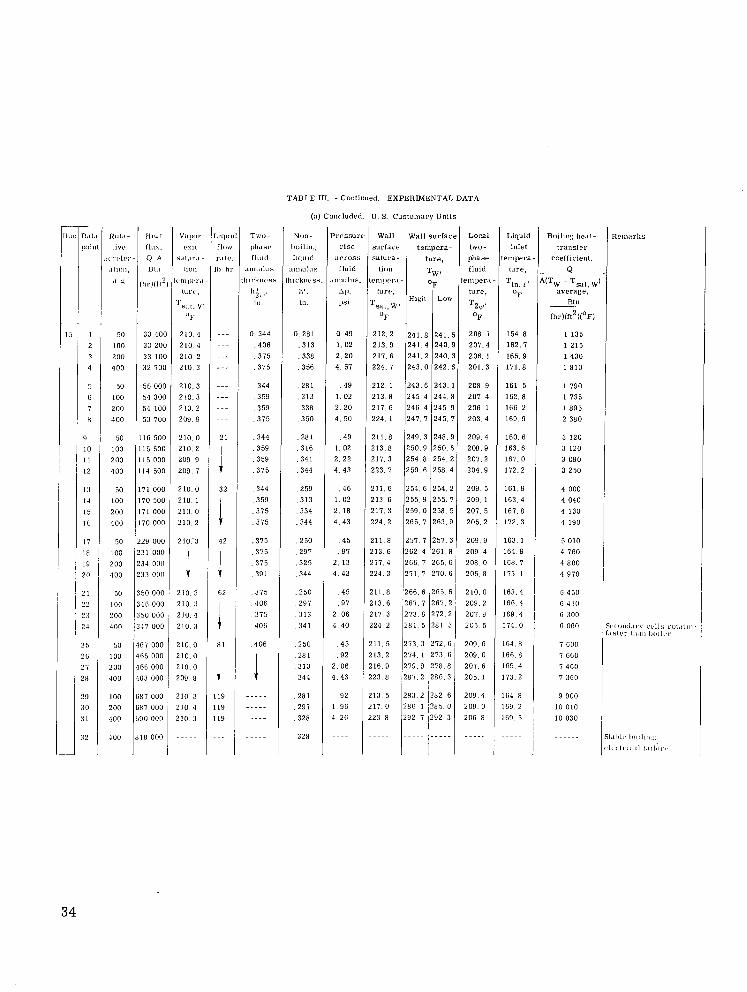
TABLE III. - Continued. EXPERIMENTAL DATA
(a) Concluded. U. S. Cus tomaiy Uni t s - I<l,,, D.1I.i
In'inl
I i 1
2 J
4
1
ti
7 H
1 10 11 12
13 14 15 I 6
17 18 19 a n
2 1 1 ??
23 I 2 4
25 i 26
3 2
~
Pressure r i s e
:irruss fluid
:,nnul"s. Ap. Psi
0 4 9 1 .02 2 . 2 0 4. 57
. 4 9 1.02 2 . 2 0 4 . 5 0
. 4 9 1 .02 2 .22 4 . 4 3
. 4 6 1 . 0 2 2. 18 4 . 4 3
W a l l Wall s u r f a c e Loca l Liquid Boilin: h ~ . t l -
surfarv t empera- hvo- inlet lransfrr s a l u r d - ture, phase tempera- coefficient.
4 T ~ , fluid t u r e , ... lion
Tl". 1 ' A(TW - TS31. M l?",l'rl'.l- oF t e m g e r a -
H q h Low tuw, ~ tu re , oF average .
OF OF (hr)(ft2X0F)
Btu Tsal,W, T 2 @ _ _ ~
212.2 241 .8 2 4 1 . 5 2 0 8 . 1 154.8 1 1 3 5 213.9 2 4 1 . 4 2 4 0 . 9 207.4 162 .7 1 2 1 5 217.6 241 .2 240 .3 206. 1 165.9 1 4 3 0 2 2 4 . 1 243 .0 242 .6 201 .3 171 .8 1810
212. 1 243 .6 243. 1 208.9 161. 5 1 7 9 0 213.8 245.4 244 .8 207 .4 162 .8 1 7 3 5 217.6 246.4 245 .9 206. 1 166.2 1 8 9 5 224. 1 247 .7 2 4 5 . 7 203.4 169 9 2 380
211.8 2 4 9 . 3 2 4 8 . 9 209.4 160.6 3 120 213.8 2 5 0 . 9 2 5 0 . 6 208 .9 163.6 3 120 217 .3 2 5 4 . 8 254 .2 207 .2 167 .0 3 090 223.7 2 5 9 6 2 5 8 4 204.9 172.2 3 250
211. 6 2 5 4 . 6 254 .2 2 0 9 . 5 161 .9 4 000 213.6 255.9 255 .7 209 .1 163 .4 4 040 217 .3 259 .0 258. 5 207. 5 167 .8 4 130 2 2 4 . 2 2 6 5 . 1 263 .9 205 .2 112 .3 4 190
Liquid il<,W r.,11,,
11, 111.
...
...
.._
_._
...
...
...
...
21
1 I 1 1
32
42
62
81
1 1 1 J
Tivu- ph.1st.
IlUld .LIIIIIII"J
thlcknvs!
,' in .
0 . 3 4 4 , 4 0 6 , 3 7 5 315
344 , 3 5 9 .359 , 375
, 3 4 4 3 59
:;::
::;; .344 . 359
.375 , 3 7 5 , 3 7 5 . 3 9 1
, 3 7 5 406
.::E 406
1 - - - I - - - -
50 100
200 400
50 100 200 400
50 100 200 400
50 100 200 400
50 100 200 400
SO 100 200
400
50 100 200 400
100
200
400
400
0.281 .313 , 3 3 8 .356
, 2 8 1 , 3 1 3 .338 350
, 2 8 1 . 316 . 3 4 1 344
.259 , 3 1 3 , 3 3 4 .344
.250 , 2 9 7 , 3 2 5 , 3 4 4
. 2 5 0 297
. 3 1 3 , 3 4 1
250 . 2 8 1 , 3 1 3 344
. 2 8 1 , 2 9 7 328
328
O F
33 400 210 4 33 200 210.4 3 3 100 210.2 32 700 2 1 0 . 3
56 000 210.3 54 300 210 .3 54 100 210.2 53 700 209.9
116 500 210.0 1 1 5 5 0 0 210.2 115 000 209.9 114 500 209 7
171 000 210.0 170 500 210.1 171 000 210.0 170 000 210.2
229 000 210.'3 231 000 234 000 233 000
350 000 210.3 346 000 210 3 350 000 210.4 347 000 2 1 0 . 3
467 000 210.0 465 000 210 .0 466 000 210.0
1
463 ooo 209.8
687 000 210 3 GH7 000 210.4 690 oon 210 3
818 000 - - - - -
257.1 262.4 2 6 6 . 7 271 .7
2 6 6 . 6 267. 7 273 .6 281 5
. 4 5
. 9 7 2. 13 4 . 4 3
45 97
2. 06 4. 40
. 4 5 92
2. 06 4 . 4 3
92 1. 96 4 .26
251 .3 261 .8 2 6 5 . 6 270 .6
265 6 1 267 2 272.2 2 8 1 . 3
211.8 213.6 217.4 224 .3
211 .8 213. 6 217. 3 224.2
211 .5 213 2 216 .9 223 8
213. 5 217 .0 223.8
209 .9 209 .4 208.0 206 .8
210 0 2 0 9 . 2 207.9 205. 5
163. 1 164 .9 168.7 173. 1
163 .4 166 4 169 4 174 .0
273 .3 274 .1 2 7 9 . 9 287 .2
2 8 3 . 2
272.6 209.6 273 6 209.0 278 8 2 0 7 . 6 286 .3 205. 1
282 6 209.4
164.8 166.8 169 4 173 .2
164 8 169.2 , 169. 5 ,
286 1 i285. 0 292. 7 1292. 3
5 010 4 760 4 800 4 970
6 450 6 430 6 300 6 060
7 G O O 7 660 7 4 6 0 7 360
9 900 10 010 10 030
209.0 206.8
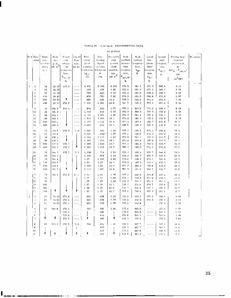
TABLE 111 - Cmwlinucd,
(11) SI U n i l s
I . i , ~ ~ i i < I T w - Yon- P L L hhurc'
I I ~ W 1 h . t ~ ~ Ii<iiliii< r ise L ( . , k . I lult l i l q l l l d , I , ross lis hr . I I I ~ W ~ U S .IIIIIIIIUS l luid
O l i l k n i , \ s . Ihi, knvss. . ~ n n u l u s .
I$<,. 11'. A p . ut,,. vni . kN m2
.... 0 , 4 7 8 0. 160 0 .414 ~.-. ,035 , 4 7 8 1.38 .... , 7 9 5 ,635 3. 10 ...- , 8 7 4 , 7 9 5 7 . 0 3 .-.. 889 ,833 14. 5 ...- 1 1 1 3 1.031 35 .8
~... , 8 7 4 . 5 5 6 1.03
.... I, 191 I . 031 4 .48 ~ ~ . . I 311 I 191 IO I ~ ~ . . I 191 I . 112 19 o ~~~- I 031 ,953 3 3 I
...- 1.112 ,874 2.07
4 H 1 031 635 I . 10
1 031 . 5 5 G ? 1.52 I :iw I 112 4 n3 I 349 I . 191 I O I
I 191 I . 151 39 3 1 285 1 230 20 7
1.112 , 8 7 4 2. 14 1.27 1 113 4 H3 1 . 4 3 1 . 2 7 10.7
1 349 1.27 2 1 4
I 1 1
9. 5 1.230 . 7 1 4 I 24
I 1 1 2 i . 0 3 1 35 n
I 51 1 27 2.H3 1 59 1.43 5 . 9 3
14 1 1 5 1 I . 11 1 59
1 .F7 1 51 12 4 1 59 1 .51 24 .8 1 35 1 27 42 7
,635 478 1 . 3 8
1335 , 4 7 8 1 . 3 8 635 , 4 7 8 1 .38
.~..
....
....
. ~. 714 460 1 . 3 8
....
-~..
~... 460 1 I :;: 5.9 714 4 1 4 1 31
-137
EXPERIMENTAL DATA
W.111 WdII surlace sorl.ire s:t1ur.1- l < ~ l , , ~ w r ~ l -
lion lure. I < , I ~ ~ I P I . : I - Tw, I
Ts;,l.W, K
lure, K
3 7 2 . 5 381.1 372 .8 381.3 373.3 381 .8 374 .3 381 .9 376.3 382 .8 3 8 1 . 2 385 .4
372.7 383 .9
313.7 385 2 3 7 5 . 2 3n6 u 3 7 7 . 4 3n7 .4 380 .7 389 I
372.9 384 .3
372 .7 38F I 372 8 3HF 8 373 .8 :in7 I 3 7 5 . 2 388 .6
382 I 393 .6
3 7 2 . 7 388.2
377 7 390.4
372 .9 3HH. 7 373 .8 390. 1
375 .2 390.7 377 9 3 9 3 . 1
381 3 395 .9
373. 1 300 .4 374 0 391. 5
372 8 3119 9
375 7 392 4
378 7 395 2 382 H 398 3
372 n 3 ~ 3 . 3
372 .8 3 ~ 2 . 8
372.H 383 0
372.8 3H5.0 572 .8 3H5.9 372 H 3HC 1
372 7 3HG 2
372 G 3x7 7
372 i 3n7 7
3 7 2 . 4 3x7 H 372 6 3x7 9
L<n..ll 1W"-
I h I S P
fluid ,~l,l,wr;,
LUrC.
T Z t . K
371. 5 371. 1 3 7 0 . 0 369 .9 368. G 366 .4
371. 5 371 .5 371 .2 3 7 0 . 6 3F9 7 36F 3
371 .5 371. 5 3 7 1 5 3 7 0 H 369 6 3tin 5
371 7 371. 7 3 7 1 . 1
371 .1
369. H 369 2
3 7 i . n 371 n 371 1
310 7
370 4 :1G9 3
371 .3
3 7 1 3 ... .
I , I.lq,nri
l<.lu~n~ra-
1Ul.P.
~ I l l l P l
Tin. 1 '
K
349 .4 340 .7 350. 1 351 .2 353 .4 3 5 7 . 8
349 .4 1 350 n
3 5 2 . 1 352 9 3 5 5 . 0 359 9
348 2
350 2 351 2 3 5 3 3 354 .7 358 2
34H ti 349 2 349 6 352 .4
354 .8 358 7
348 3
341) 7 3 5 1 . 2 353 H
.l.ll, 5 301 4
( i .
n<nll!l:: I,I'.lI-
Ir.,l,slc.r ,1W111,'1~~111.
9 . Ts.L~.u.)
kW
( 1 A K 1
3. 71 3 . 76 3. ti9 4. 07 4 55 G. i n
9 . 4 5 9 . 3 4 9. 17 9 B5
10. 4 11 5
13 5 12 9
12 !I 1 :I :I 14 0
15 4
23. C
23 0
22 4
2 3 4
2 3 !I
24 II
3 2 5 32 0
3 1 7 :I2 7 3 3 7
:I:$ 7
2 5 2 5
35
:I2 08 3 7 2 4 3 2 02 372 .4
2 5 , 3 2 02
25 IO(i.0
372 .4
372 4
33H H
350 3 35b 4
335 2 3-11 7 34H H
3 5 3 2
3 1 5 1
341 9 349 5 ' 3 i . i C
3 0.1 3 1 3
:i i n
ti (19 H (19
7 OH
7 H8
1-1 .I 1.1 4 1 4 2 1 4 1
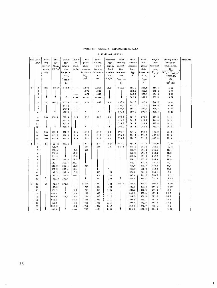
TABLE 111. - Continued. EXPERIMENTAL DATA
(b) Continued. 9 Uni t s -
Rota- t ive
a c c e l e r - ation,
a /g
200
1 1 1
200
200
Heat Vapor Liquid flux, exit flow Q;A, s a t u r a - r a t e ,
kW/m2 tion kg/hr t e m p e r a -
t u re ,
T s t , V' K
29 .97 372 .4 ---- __._ 1 1 1:::
103.8 372.4 . ---- 312.4 ---- 312.4 ---- 372.3 ----
216 .7 372.4 5.4
I I 200 363. 5 200 363. 5 200 363 .5
25 32. 18 106 .0 180. 5 366 .0 555.3 735.1 120 549.0 372 .3 189 .3 107 .3
1 32.18
25 32. 18 107 .3 220 .9 444.9 662.6 946. 5
TWO- phase fluid
annulus thicknes!
h i @ cm.
I 372 .4
;E 372.3 9. 5 372 .3 9 . 5 372 .3 9 . 5
312.4 ----
4 . 5
.... I :::: 3 7 2 . 5 1 9 . 5 372. 5 29. 1 372. 5 1 5 . 0 372 .4 10.4 372. 5 5 . 0 372 .5 - - - - 372. 5 - - - -
372. 5 - - - - ..-.
1 I:.: 372 .4 17 .7
25. 0 15. 0
0.814 ,874 .874
j,
, 874
Non- boiling liquid
annulus thickness
h' ,
.912
i,
1
P r e s s u r e Wall rise s u r f a c e
a c r o s s s a t u r a - fluid t ion
annulus, t e m p e r a - AP, hre,
W m Z Tsat, w p K
1 4 . 9 376.3
I 1 1
14.8 376.3 376.3 376.3 376 .2
376.3 14 .8 316.3
316.2 1 316.2
14 .5 376.2 14. 5 376.2 14 .5 376.2
2 . 0 1 3 7 3 . 0 1.17 372 .8
I 1 .24 1.24 1.38 1
1.24 372 .8 1.24 1. 17 1 .17 1. 17 1 . 1 0 1.1: 1 .17 1 .38 t
, 912 ,912 ,912
1.11 .714 , 7 9 5
Loca l two- phase fluid
t empera - t u re ,
TZW'
714
Liquid inlet
t empera - t u re ,
Tin, 1 ,
0.676 . I14 . I14 . I14 754
. 7 9 5 , 7 9 5 154
, 7 9 5
Run Data lwint
3 1 2 3 4
5 6 7 8
9 10 11 12
13 14 15
4 1 2 3 4 5 6 7 8 9
10 11
I Cm.
369.9 310.1 369.8
370.6 370. 5 370.4 370.4
370.9 370.9 370.9 371. 1
370.5 371 .3 311 .0
3 7 1 . 0 371 .1 311.3 3 7 1 . 1 371.9 312. 1 312.4 372 .1 312 .0 371 .7 371 .3 370.6
370 .6 371 .3 371.6 371.8 371.9 372. 1 371.8 371.7 371 .0
0 .841 , 8 4 1 ,848 ___..
, 8 3 3
1 1
, 8 3 3
, 8 1 0 . a 1 0 , 8 1 0
.874
.396
V , 4 3 7 , 4 5 2 493
0 431 ,422 414 396
,396 , 3 8 1 396
, 3 9 6 ,478
352. 5 354.4 358 .9
346.3 348.4 350.1 355.1
343.6 347.8 352 .0 356 .7
341 .0 350 .0 360 .3
339. 0 345.9 346 .9 346 .2 347.1 349.4 351. 1 352.3 352.4 352.8 353 .2 353.8
356 .9 355 .3 353.4 351.4 351 3 352.2 353 2 333.G 354.4
s u r f a c e t e m p e r a -
ture,
TW' K
381.9 382.0 382 .1 382.2
387.3 387.4 387.6 387.2
391.3 391.2 391.2 391 .1
394 .1 394.2 394.2
382. 7 381. 5 388.6 390.3 392.3 394.1 397.3 393.6 390.3 381.8 386. 6 383 4
382.9 386 9 389.2 391.9 394 .3 396.8 392.9 389.9 386.9
3 r 9 . 9 I 347 .1 I
36
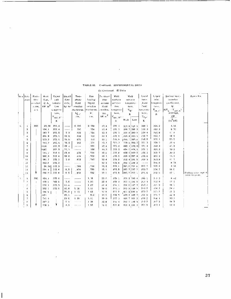
TABLE 111. - C<mIinwd. EXPERIMENTAL DATA
(b] Conli~~ued. SI Units
'1 cssure r i se
.,'I."SS
rluid nllulus.
kN m2 AI>,
13.4 1 3 . 4 1 3 . 4 13 1 13. I 13. 1 12.4 10 3 12 .8 13. 1
1 3 . 4
1 3 . 4 13.4 13. 1 13 1
25 G 22.4 21 4 19 0 17 0
15 9 19 0 22.n 28 G
,111 w:lll surI:i(.c s.lt"r.l-
l i o n lctn~>crd -
TsL,l. w. K
37ti 1
376 1
376 1
375 9 375 .9 3 7 5 . 9 375 8 375 .2
lure.
3 7 5 . 8 375.9 375 .9 3 7 5 . 9 376. 1 375.9 3 7 5 9
379 1
379 3 3 i n I 3 7 7 . 5 3 7 7 2 376 7
3 i 7 5 318 4 379 n
Hc. . i l V . I I ~ , I . Ilus. cxil
9 A. u l u r i l -
I ~ W m2 lion 1 ( . m In'r.1-
i u w ,
TSLt. V' K
29. 56 372 .4 104. 1 372.4 i n 1 I 372.5 366 0 372 .4 555.3 372.4 147 I 372.4 104 372 5 492 3 1 2 . 5 747.7 372.4 366.0 372 .4 i n 1 . 1 372.3 1 0 3 . 8 372.3 26. 19 372.5
364 4 372 4 36ti 0 372.4
10.1. 1 372.6 179 8 362.6 370. 1 372.5
367 6 17H 3
K
Hinh
382 9 388 I 3 9 1 n 395 n 398. I 399 n
404.9 402. 7
400 ti 398 0 392.4 388 5 3 8 2 . 0 397 7 307 .7
391 2 393 1
39H 0
399 401 2 403 2 401 390 I
384 4
Arlttid
r:11c. 'g 111.
riorv
....
....
5. 0 IO. 0 15. 0 2 0 . 0 29. 1 37. 7 20 .4 10.0
5. 0 ...-
....
9 . 5 9 5
....
5 . 0 1 1 . 4 1 6 . 0 20.0 2 9 . 1 20 0
9 5 4. 5
~
Low
382 3 388 3 390 t(
395 4 3 g i . n 399 I
404.n 402. 5
400 2 397 . t i 391 9 388 2 381 H
397 3
397. 1
390 4 :191 9 387 7
9 ' 3 8 9 5 400 n 402 8
7.101 3 3% 5 391 7
TWO- 111:1se
rluid Inl lulus i i< .knrss .
1';d ('11,.
0.795 795 n33 833
, 8 7 4 912
....-
.....
814
, 8 3 3 874
.....
,795 n14
, 8 7 4
.....
...-.
.....
1 19 1 15 .....
1. 19 .....
.....
Nun- liuillng liquid
1nnulus
i i cknrss . I,'.
1.111.
0 754 7 54 754 739 732 72 I 69 1
. 556 714
, 732
. 747 .....
, 7 5 4 739 732
1. 59
1. 35 1 27 I . 11 1 0 3
912 1 . 1 1
1 38 1 8 3
LII(.ill iwo - ]>I,:, SP
r i u l c i .1!,1),.l'a- lur',,
T 2 s . K
3tio 1
370 0 370 4 370 9 370.9 371 .3 371 4 371 1 370. 3 370. 8 369 5
360 5 370. 7 3 7 1 . 0
3G9 1 3h!l 4 370 :I
370 2 370 7
3 7 1 0
370 2 J i O 2
3GR 9
Liquid l n l d
: I ~ I ~ J I ' : L -
IUI'P.
Tin, 1 .
K
354 2 353 3 : is i , n 357 1
357. I 35n. I 360 .3 361. 3 361 I 3 t i l 3 360.9
35H. ti 359 2 354 7 350 h
3,s 3
,157 o .I5h 0
.Ai4 2 ,'< i ., 2 :3,-,1, i :m I .I112 3 J1,O 1
37
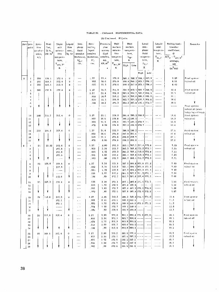
TABLE III. - Continued. EXPERIMENTAL DATA
(b) Continued. SI Units
3 9 4 . 0 393 .8 393 .3 392 .7 393 .2
Heat Ilux, 9 'A <W 'n
104. 1 104. 1 104. 1
178 9
1 171. 3
I I
864. 4
3 2 . 0
1 1
1 1 I
06. 0
06. 0
I 79.8
72. 0
59.1
392 .7 369 .7 368. 392. 7 369 .8 368. 392 .6 369 .8 369. 3 9 2 . 3 3 7 0 . 3 369. 392 .8 370 .7 370.
vagor exi t
satura lion
emper: ture,
Tsat , \i K
372.4 372 .4 372 .4
372.4
1 372.4
i I
372.4
372 .6 372.6 372.6 372. 5
_....
396.8 396 .2 395 .7 395 .2
.iqu f l O \ rate ' g I
0 0
0
0
1 0
I 1 0
0
I 1
I I 1
0
0
I 0
0
0
._... ..__. ....
396.3 369 .9 - - - - 3 9 6 . 1 ----- - - - - 395.3 370.7 - - - - 394.9 370 .7 - - - -
398.6 398 .3 - - - - - - - - - 397.9 397 .6 - - - - - - - - - 396.9 396 .7 - - - - - - - - - 396.2 396 .0 - - - - - - - - -
383. 1 382.7 371 .4 370.1 383.2 383 .0 371 .2 370. ' 383.2 383 .1 370 .9 370. I 383. 7 383 .6 370. 5 370. 384. 7 384.4 371 .2 370.
387.2 386 .8 371 .8 371.: 387. 1 386.7 371 .4 371.: 387 .2 386 .8 371 .3 371. 387. 5 387. 2 371. 3 371. 387. 7 387. G 372.4 372. :
387 1 386.8 371.4 371.: 387 .2 386 .9 - - - - - 387.3 387 .1 371.1 370. 387 .6 387.4 372 .4 372.
389 .2 389 .0 371 .7 371 . ( 389 .3 388. 6 - - - - - 389.0 388.8 371 .3 371 .1 389. 1 389. 0 - - - - - - - - - - 388.9 388.8 - - - - - ----.
391. 1 390.4 371 .4 371.2 390 .7 390 .6 - - - - - - - - - - 390.9 390 .8 - - - - - - - - - - 390.6 390 .5 - - - - - - - - - - 390.6 3 9 0 . 5 - - - - - - - - - -
392.5 392 .4 - - - - - - - - - - 392.4 3 9 2 . 3 - - - - - - - - - - 392.2 3 9 2 . 2 - - - - - - - ~ - - 392. 1 392, 0 - - - - - - - - - - 391.9 391 .9 - - - - - - - - - -
Non- oiling iquid Ilnulus iicknesr
h' I
cm.
1 27 , 9 5 3 . 6 3 5
1. 59 1 . 2 7
, 9 5 3 , 6 3 5 . 556 _.__.
1.27 , 9 5 3 , 6 3 5 , 4 7 8
1. 27 , 9 5 3 , 6 3 5 , 4 7 8
1 .27 , 9 5 3 , 6 3 5 , 3 1 8 . I60
1. 27 , 9 5 3 . 6 3 5 ,318 . 160
. 9 5 3 , 6 3 5 . 318 . 160
1 . 2 7 , 9 5 3 , 6 3 5 318
. 160
1. 27 .953 . 6 3 5 ,318 .160
1 27 , 9 5 3 , 6 3 5 , 3 1 8 . 160
Pressu r i s e
a c r o s Iluid
1nnulur
AI], . kN, ni'
21.4 16. 6 11.5
25. 6 2 1 . 4 16. 6 11. 5 1 0 . 2 __..
21.4 16. 6 11. 5 8 .96
21.4 16.6 1 1 . 5 8 .96
2 . 9 0 2 .34 1. 72 1. 03
. 6 9
2 . 9 0 2 .34 1. 72 1. 03 . 6 9
2 .34 1 . 7 2 1. 03
. 6 9
2 . 9 0 2 .34 1. 72 1. 03
. 6 9
2 . 9 0 2. 34 1. 72 1. 03
. 6 9
2. 90 2 .34 1. 72 1. 03 . 6 9
Wall surface satura-
tion emlEra.
ture,
'sat, W' K
378.0 376.8 376.6
378.9 378 .0 376.8 376 .6 376 .2 _..._
378.0 376.8 375.6 374.9
378 .0 376.8 375.6 374.9
373.3 373.2 373.0 372.8 372. 7
173.3 173.2 372.9 172.8 172.7
173 1 172 9 172. 7 172.6
173.3 173. 1
172.9 172. 7 172. 6
,73.2 ,73. 1 ,72. 9 J 2 . 7 3 2 . 6
73 .2 7 3 . 1 72.9 72. 7 7 2 . 6
Liquid inlet
empera ture.
Tin, I ' K
Boiling heat- transfer
coefficient. 9
(Tw Tsat.w average,
kW
Im2)IKI
-~
9 . 8 2 8 . 91 8 . 43
12. 4 1 1 . 7 11 1 in. G
10. 0 .....
14 6 1 4 . 0 13. 6 13. 4
17 8
17 4 17 1 17. 2
3 . 3 5 3. 25 3. 15 2. 99 2. 71
7. 69 7. 69 7. 52 7. 26 7 .09
7 .66 . 7. 46 7. 29 7. 07
11 .4 1 1 . 4 1 1 . 2 11.0 1 1 . 1
15. 5 15. 5 15 .2 15. 3 1 5 . 2
19 2 19.2 19 .1 19 .1 19. I
~
at. >it
~
1 2 3
4 5 6 7 8 9
0 1 2 3
4 5 6 7
1 2 3 4 5
6 7 8 9 0
1
2 3 4
5 6 7 8 9
3 I 2
3 1
J
7
1 1
ROLL - l ive
ccelct ation,
a h
200 2 00 200
200
I 200
I I
200
25
I 1
1 1 I
25
25
I 25
25
25
Local hvo- phase fluid
tempera- ture,
TZO?' K
Wall sur lace
tempera- ture,
TW' K
389.1 3 8 8 . 8 388 .0
...._
...._
.....
...._
.....
...._
372. 5 372. 5 ...._
...._
372.6
372 .4
I 372. 5 372.4 372 .4
.....
...._
...._
._... ...._
372.4
I 1
372.4
...

TABLE Ill . - Continued. EXPERIMENTAL DATA
(b) Continued. SI Uni t s
w a l l ;urface iatura-
lion mlxra-
)a 1;1 Boinl
1 2 3 4 5
6 7 8 9
I O
I I 12 13 14 15
1G 17 18 19 20
21 22 23 24 2 5
2G
Wall sur iace Local tempera- hvo-
ture, iihase TW 9 fluid K tempera-
? O h -
l ive . C C l f 2 r
ition, :1.'c'
25
I I ! I I
25
25
25
25
25
High
Heal [lux,
X A , W,.l?,2
32.02
! I I ! I
OF. 0
79.8
8 2 . 1
66. 0
79.8
Low TZU'
K
Vapor exit
ialura - l ion
.ni Ixra - lure,
rsat, V' K
372.4 372 .3
1 372.4
!
I I
372.4 372 .4 372 .3 3 7 2 . 3 372.3
372 .3
372. 3
372.4
373 .1 372 .9 372 .7 372 6 372.4
373. I 373.0 372 .8 372 .6 372.5
372 .7
,iquic [low -ale, g hr
0
I ! I I I
0
0
0
0
.--
390.5 390 2 - - - - - - - - - - 390.3 390.2 - - - - - - - - - - 390.2 390 .0 - - - - - -..-. 390.1 390.1 - - - - - - - - - - 390. I 3 9 0 . 1 - ~ - - - - - - - -
391. I 391. 0 - - - - - - - - - - 391.0 390.9 - - - - - - - - - - 391.1 391 .0 - - - - - - - - - - 391.0 390 .9 - - - - - - - - - - 391.3 391 .2 - - - - - - - - - -
388.9 388.8 371 .3 371 .2
TWO- phase fluid
.,,""IUS
i rkaess ,
h i d c m .
._.__
...__
___..
...._
._.._
...._
._...
...._
.___.
_....
.._._
...._
.....
__...
.....
.....
.....
._...
....-
.....
....-
._...
.....
____.
.....
_....
NO"- boiling liquid
allnulus i irkness ,
h' , C",.
1 . 2 7 , 9 5 3 , 6 3 5 , 3 1 8 ,160
1 . 2 7 , 9 5 3 , 6 3 5 , 3 1 8 . 160
1 . 2 7 , 9 5 3 ,635 , 3 1 8 . 160
1 . 2 7 , 9 5 3 , 6 3 5 , 3 1 8 . 160
1.27 , 9 5 3 , 6 3 5 , 3 1 8 . 160
, 4 3 7
)ressure r i s e
a c r o s s fluid
Innulus,
AP, kN;m
2 . 9 0 2 .34 1 . 7 2 1. 03
. 6 9
2 . 9 0 2.34 1 . 7 2 1. 03 .69
2 . 9 0 2 .34 1 . 7 2 1. 03
.69
2 . 9 0 2 .34 1 . 7 2 1. 03
. 6 9
2 . 9 0 2 .34 1 . 7 2 1. 03 .69
1.31
tu re ,
sat , W' K
373.2 373 .0 372. 7 372.6 372. 5
373.2 373 .1 372.8 372 .7 372.6
373 .2 373 .1 372.8 372.6 372. 5
Liquid inlet
'nipera - lure,
Tin. I ' K
...-. _....
.....
.....
.....
.....
.____
._.__
_....
..__.
.....
_....
.____
___..
.....
.....
.....
.....
~-...
_....
._.._
.._._
...._
.....
.....
__...
Bailinc heal- transfer
coell icieat.
Q . .. .(Tw - Tsal, 1")
(&(K)
average, kW .-
3 . 52 3 . 30 3 .24 3 . 0 2 2 .84
7 . 9 7 8 . 1 2 7. 55 7. 32 7 . 21
11.5 1 1 . 8 1 1 . 4 1 1 . 2 10 .8
16 3 16. 3 I F 2 16 1
I f i . 0
20.4 20 .4 20 0 1 9 . 9 1 9 . 5
11. 1
39

TABLE 111. - Coillinued. EXPERlMENTAL DATA
(b) Conlinucd. SI U n i l s
3 7 2 . 6 372 .6 372 .6 372.4
373. 1 373 .0 372.8 372 .9
374.1 374. 1 374.0 374 .3
376.4 376 .2 376 .1 376 .1 376 .2
380 .6 380.3 380 .3 380 .1 380.1
380 .3 380 .0 380 .1 380 .0 379.9 380 .0
316. 5 376.2 376 .0 375.8
374 .2 373 .9 373.9
):I 1
ioi!
1 2 3 1
5 6 7 8
9 10 11 12
13 14 15 16 17
18 19 20 21 22
1 2 3 4 5 6
7 8 9
10
I1 12 3
4 5 6
7 8 9
-
-
__ H i g h Lon.
376.8 376.8 371. 1 3 7 0 , s 379.2 379. 1 370 .6 370.4 382 .6 382.4 370 .2 370. 1 376.9 376.9 371 .1 370. E
378. 1 378. 1 370.7 370.4 379.3 379.3 370.2 369.9 382.4 382 .2 370 .3 370. 1
376.8 376.7 370.8 370.6
378 .3 378 .2 3 7 0 . 0 369 .8 379 .9 379 .7 369 .7 369. 5 382 .7 382 .6 370 .0 369.6 378. 1 378. 1 370 .0 369. 6
371.7 311 .7 369 .3 369. 1 381 .0 380. 7 368 .2 367.8 381.2 381. 1 368.6 368 .2 383 .4 383 .4 369 .0 368 .9 377 .2 377.1 369. 5 369 .4
376.0 375.9 310 .1 3 1 0 . 0 380 .0 379.9 367 .8 367.4 383 .3 383.2 365.9 365. 6 384.9 384 .8 365 .6 365. 1 387.6 381 .3 366 .3 364. I
374.4 374 .3 310. 7 370 .4 377 .5 377 .4 368 .2 367 .9 382.2 382.2 366.4 366.2 385. 1 384 .6 366 .6 365 .8 386 .6 386 .4 367 .7 366 .6 374 .9 374.8 370 .3 370 .0
376.4 376 .3 369 .4 369 .2 380. 5 380 .4 369 .4 368. 7 381 .3 381.2 369.3 369. 1 382.2 382. 1 369.2 368 .3
317 .2 377 .2 370 .1 369 .8 319 .2 378.7 369.6 369.3 381.8 381. 7 369. 1 368. 7
Rob1 - live
rcclfl nlion. a ,,
25
I i 50
i I
100
200
1 1
400
400
I
200
i 100 100 100
50
50 50
25 25 25
372.8 372.8 372.8
372.3 372.3 372. 2
Heat i1lK.
9 A. w 111
4.3: 13. 5' 32. 0:
4. 3:
3. 6! 12.9 : 31.5i 3. 6!
3. OL 12.31 30.8: 3. OL
2. IC 11. 3$ 20. 6:
39.81 2.1f
.9: 10.1( 19.43 B . 71 17.33
.92 IO. 1c L9.43 !8.71 17.33
.92
2. 15 1 . 4 2
10. 67 19.88
3 .08 2.30 ,o. 79
3. 70 2 94 1. 42
4. 32 3. 57 2 .02
377 .3 377 .2 370 .2 369 .8 353 .3 380.2 380. 1 369. 7 369. 5 354. 1 382. 7 382.6 369 .9 369. 7 354. 1
377.4 377 .4 370.8 370 .7 355 .2 379. 5 379.4 370 .2 369 .6 356 .4 382.4 382 .3 370.4 369 .9 356. 5
vapor ex i 1
s;llor;l
1lOll
cnllx'r. 1"I.C.
TS.,I. v K
372.0 371 .9 372 0 371.9
3 7 2 . 1 372 .0 311 .8 371 .9
371 .9 372 .0 378 .1 372 .1
372. 0 372. 1 372. 1 372.0 371.9
372 .0 371.9
1 371.9 371.8 371 .9 371.9 371 .8 371 .8
371.8
1 371.8 371.8 371 .8
371.8 371 .8 371.8
371.8 3 7 1 . 8 371 .8
Liqui l lO\V
r a t ? k- hi
....
....
....
.-...
.....
.....
.....
.....
.__..
.....
.....
.....
..-..
.....
.....
_ _ _ _ ....
_...
....
__._
__..
....
.._.
_ _ _ _ __..
__._
_...
..__
....
..--
__..
....
._..
....
Two - ph.1 sc flUlC1
allllulus iirkncs!
'li,,. Pl l l
__.._
....-
0.833 , 7 5 4
.....
. I 9 5 , 1 5 4 ____.
_ _ _ _ _ ____.
.874 .....
__._.
__...
.....
_ _ _ _ _ _....
._.._
.....
.__..
...._
.....
.....
_ _ _ _ _ .._..
_.._.
.....
.....
._...
__._.
.....
__.._
.....
_._._
.....
..___
__...
.....
.....
.....
.....
Noli- boilinn liquid
nnnu1us ihicknrs
11' ,
cn1.
0 .833 , 8 3 3 , 7 1 4 , 7 1 4
833 754
, 7 1 4 , 7 5 4
, 8 7 4 , 8 3 3 79 5
, 8 7 4
. 9 5 3 , 8 7 4 . 8 59 , 8 4 8 , 9 1 2
.986 , 9 5 3 , 9 5 3 ,912 , 9 1 2
0 .953 , 9 2 2 .912 , 9 1 2 , 9 1 2 . 9 3 0
1 .016 , 9 5 3 . a 8 9 .848
, 9 5 3 .866 , 8 3 3
, 7 9 5 . I 5 4 . 714
, 6 3 5 572
. 516
)ressuI rise
fluid lllllUlUS
AI).
kN in2
acres:
2.07 2. 07 1. 86 1 . 8 6
3 .79 3. 52 3. 38 3. 52
7. 72 7. 38 7.03 I . 72
16. 6
15. 5 15. 2 15. 1 16.0
34. 1 33.1 3 3 . 1 31. 9 3 1 . 9
3 3 . 1 3 2 . 1 31.9 31 .9 31.9 32 .3
17. 6 16. 6 15. 7 15. 1
8 . 4 1 7. 65 7.38
3. 65 3. 52 3.38
1 .72 1 59 1. 45
Wall surlace SLLIUL'B -
lion empera .
lu re .
TSJI. W' K
Wall sur face tempera-
ture,
Loca l hvo - ph:tse fluid
tempera- ture .
TZk.. K
Liquii inlet
emper tur?.
Tin. I K
342. 8 346. 2 348.2 349.4
151.3 151.7 152.7 152.4
153. 1
154. 0 154. 3 152. 6
151. 3 152. 1 i53.8 855.4 6 2 . 2
50. 7 50.8 51. 7 52. 6 53.1
4 4 . 4 46. 3 47.6 4 9 . 3 50. 1 48. 4
48. S
49.4 51. 1 52. 7
50.8 52. 1 5 3 . 3
Boiling lieat - 1 ran der
c o e l l i r k n l .
2 -. -. -. . . .
i(T\,. - Tsal . \ r
( "A(K)
average , kW __
1. 03 2. 06 3 .22
97
. 7 4 2. 05 3 . 3 1
. 9 7
. 7 4 2. 14 3. 56
. 8 l
....
2.47 4 . 1 1 4 . 0 1 _ _ _ _ _._.
_ _ _ _ . __..
5. 61 6 . 38
_ _ _ _ ....
....
5. 96 7. 18 ._._
....
2 . 7 1 3 . 9 2 4. 76
1 . 0 2 2 .46 3 . 9 0
. 8 4 1. 77 3 .18
. 8 5 1.88 3. 15
40
_. . . .. ...
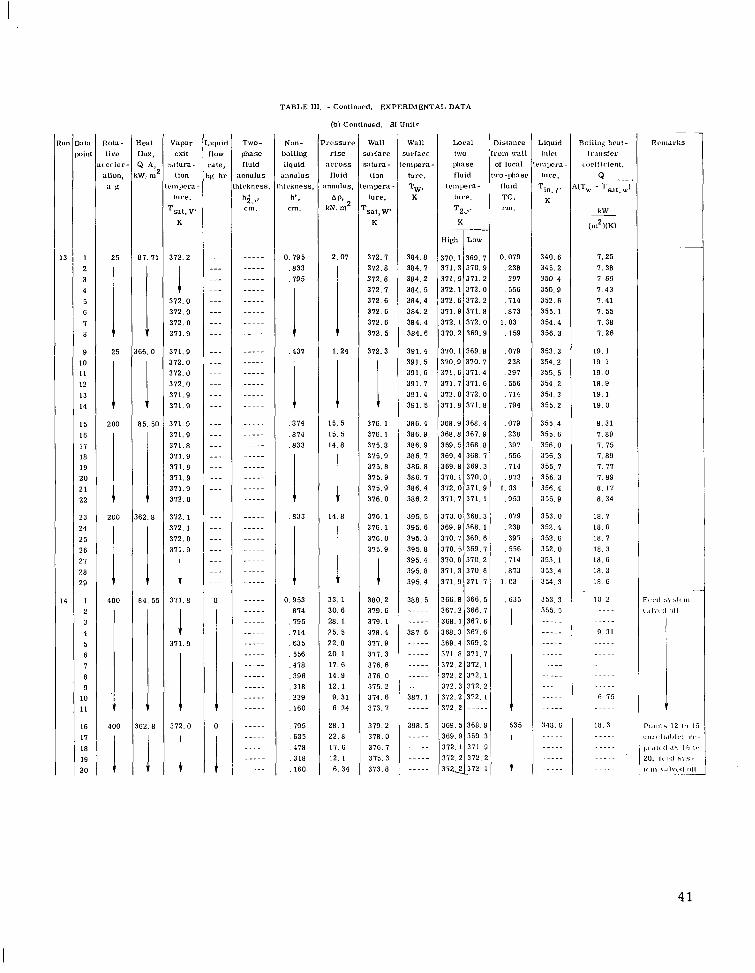
#:,til oinl
1 2 3 4 5 6 I 8
9 IO 11 12 13 14
15 16 1 1 18 19 20 21 22
23 24 2 5 26 27 28 29
1 2 3 4 5 6 I 8 9
IO 11
16
11 18 19 20
TZ,,. K
High
310.1 311.3 311.6 312.1 312.6 311.9 312.1 310.2
310.1 170.9 311.6 311.1 372.0 311.8
368.9 368.8 369. 5 369.4 369.8 370.1 372.0 371. I
310.0 369.9 310 .1 310. 5 310.8 311.3 311.9
366.8 361.2 368 .1 368.3 369.4 311.8 312 .2 372.2 372 .3 372.2 372.2
369. 5 369 .9 372. 1
372.2 3-312.
Low
369. I 310.9 311 .2 312.0 312.2 371.8 372 .0 369.9
369.8 310. I 311.4 311.6 372 .0 311.8
3 6 8 . 4 367.9 368 .8 368. I 369.3 370.0 371.9 311. 1
368.3 368. 1 369.6 369 .7 370 .2 310 .6 3 1 1 . 1
366. 5 366 .1 367 .6 367 .6 369 .2 3 7 1 . 1 312. 1 372. 1 312. 2 372. 1 - - - - -
368.9 369 3 311 .9 312 .2
1
J
TWV- phase fluid
annulus i ivknrss.
I$.,. cm.
.....
.....
..___
_ _ _ _ _ .____
._.__
..... __..-
___._
.....
..___
.....
..... __.._
.____
..__.
.....
.....
..___
.____
__._.
.....
..__.
.....
.....
.....
.....
.....
.....
.....
..___
.....
___..
___..
.....
.._._
.....
.....
.____
.....
.....
.....
TABLE 111. - Continued. EXPERIMENTAL DATA
(b) Continued. SI Uni l=
Wall iurlnce
ZLLurB- lion
")Era - lure,
s a t , w K
312. I 312.8 372 .8 312. I 312.6 312 .6 312 .6 312.5
312.3
I 316. 1 376.1 315.8 315 .9 315.8 315.9 375 .9 316 .0
316 .1 316.1 316 .0 315.9
1 380.2 319.6 319. 1 318.4 311 .9 371 .3 316. 6 316 .0 315 .2 314 .6 313 .7
319 .2 318 .0 376. I 375 3 373.8
Wall u r h c e mpera - lure.
TW 9
384.8 384. I 384.2 38r . 5 384.4 384.2 384.4 384.6
391.4 391.5 391 .6 391. I 391.4 391. 5
386 .4 386 .9 386.9 386. I 386.8 386. I 386.4 386 .2
395 .5 395. 6 395 .3 395 .8 395.4 395.8 395 .4
388 .5
____.
381. 6
..... 381 1
398.5 ..__.
Liquid inlet ml*m - lure.
Tin. 1' K
340.6 345 .2 350.4 350.9 352 .6 355.1 354.4 356.3
353 .3 354.2 355.5 354.2 354.3 355.2
355.4 355 .6 356.0 356.3 355. I 356.3 356.4 355.9
353 .0 352.4 352.6 352. 0 353 .1 353.4 354 .3
353 .3 355 .5 ..... --_._
- - _ _ _ --.._ - - _ _ _ ..--.
..... -.-.. .__..
348 . 6 ..... .....
-._..
.....
Bailing liriil- Ir'lnsfer
c orlfirienl.
Q ..-. Tu. - TSlt.W'
k W
(iii2NK)
__
I. 25 I. 38 I. 66 I. 43 I . 41 I . 55 I. 38 I . 26
18. 1 19.1 1 9 . 0 1 8 . 9 19. 1 19. 0
6 . 31 I . 89 I. 1 5 7.89 I . 77 I. 89 8 . 1 1 8 . 3 4
18. I 18. G 18. I 1 8 . 3 18. G
1 8 . 3 18 G
10 2
.....
9. 31
.....
.....
.....
.....
G 1 5
18.3
41
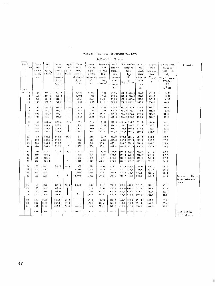
TABLE I11 - C o i ~ ~ l u d c d . EXPERIMENTAL DATA
(I,) Conrludrd. SI Ulli lS
Wall surra?? salurd-
1lOll
~ ~ I I I ~ P L ' P -
I"1.L'.
rsnt, W' K
373.2 374 .2 316 .2 380 .2
373.2 374. 1 376.2 379 .8
373.0 374. 1 376. 1 379.6
312 .9 374. 0 376. 1 379.9
373 .0 314. 0 316. 1 319.9
373.0 374.0 116. 1 179.9
Jd
" I '
I 2 1
4
5 6 7 8
9 10 11 12
13 14 I 5 I6
17 I8 19 !O
1 2 3 4
5 b
8
9 0 1
2
-
Wall surfa tempera
ture.
TW 8
K
H I $ Loa
3 8 9 . 7 389. 389 .4 389. 389 .3 388. 390 .3 390.
390. 7 390. 391 .7 391. 392 .2 391. 392 .9 391.
393 .8 393. 394 .7 394. 396 .9 396. 399.6 398. '
396 .8 396.1 397. 5 397: 399 .2 398.! 402 .9 401.!
398. 5 398.: 401. 1 400. t 403. 5 402. f 406.3 405.:
403 .4 4 0 2 , s 404. 1 403.E 401.3 406. € 411.7 411.f
m I i . t - I I V , .
I ('I 1, I
.1111),1.
.L I:
50 100 200 400
50 100 200 400
50 100 200 400
50 LOO 200 400
50 100 200 400
50 100 200 400
50 100 200 400
100 100 100
io0
H L l I
I k X
Q A iW ,I
105. 104. 104.1 103.:
116. ' 171.: 110.. 169. f
367. t 164. 162. € 361. i
539. ! 537. 9 539. 5 536. 4
122.5 '28 .8 '38 .3 9 5 . 1
04 192 04 '9 5
73 G I 70 61
67 67 77
E 1
v.ipL" CY11
s.IIUr.1
l i w i
211,1,,.,'
t u n . .
rs.ll. \.
K
372.2 312.2 312. 1 372.2
372 .2 372.2 372. 1 311.9
372 .0 312. 1 371.9 3 1 1 . 8
372 .0 372. 1 372.0 372 .1
372.2
1 1
372.2
172 0 312.0 172 .0 $71.9
172 2 172. 2 172.2
> L I I L
I I U
r.111 ;g I
...
...
...
...
...
_ _ _ _..
...
9 .
1 1 1 I i
14.
19.
!8. 1
,6. 8
4 . 0 4 . 0 4. 0
_ ~ .
Twu - I,llllh(.
r iul( i
annul"!
i i ck iws
( 7 .
C U I .
h i
0.814 1. 031 , 953 .953
, 8 7 4 .912 , 9 1 2 , 9 5 3
.E74 , 9 1 2 , 9 1 2 , 9 5 3
, 8 7 4 , 9 1 2 .953 . 953
, 9 5 3 , 9 5 3 .953 , 9 9 3
, 9 5 3 1.031 . 9 5 3
1 .031
1 031
i .....
_....
Non - IlOi li I,$
l iquid ;tnnulu! !iirknc>s
I,'. 1.m.
0. 714 , 7 9 5 , 8 5 9 .904
, I14 . 7 9 5 , 8 5 9 , 8 8 9
, 7 1 4 , 8 0 3 .866 , 8 7 4
-658 , 7 9 5 .E48 , 8 1 4
, 6 3 5 , 7 5 4 .826 , 8 1 4
635 , 7 5 4 , 7 9 5 ,866
. 635
. 714 795
, 8 7 4
.714
. I54 833
. 8 3 3
'1.(.55,1
rls? i l C I ' 0 S
f l u i d l l l l l U l "
All, kN 111
3. 38 7. 03
15. 2 31. 5
3. 38 7. 03
15. 2 31. 0
3. 38 7. 03
15. 3 30. 5
3.11 7. 03
15. 0 30. 5
3. 10 6. 69
14. 7 30. 5
3.10 6. 69
14 .2 30 3
3. IO 6. 34
14. 2 IO . 5
6. 34 3 . 5
19. 4
_.._
172.8 173. 8 175. Y 179. I
401.2 406 .8 407 .6 401 .3 410 .8 410 .2 414.9 414.4
.... 1 .....I .....
Lur.1 I\?"-
llll.151
I lu id P m in, 1
ture.
T 2 N K
370.9 370.6 369 .8 367 .2
311.4 370.6 369.8 3 6 8 . 3
371. I 371.4 370 .4 369 .2
371 .7 371. 5 310 .6 369.3
371 .9 371. I 310.9 370.2
372.0 311. 6 170.8 369. 5
$11 .8 171.4 170. 7 169. 3
171. 7 111.4 170 2
....
Llqul Illlrl
clllj>cr
1Ul.C.
Till. I K
341.3 345 .7 341. 5 350 .8
345 .1 345.8 347. I 349.7
344. 6 346.2 348. 1 3 5 1 . 0
345 .3 346. 1
348.6 351.1
345.9 146.9 349. 1 351.5
146. 1 147.8 149.4 152. 0
846. 9 48 0 49 .4 51. 6
46 .9 4 9 . 3 4 9 . 5
....
Boilin. 1~r.11- 1 r.111s1 rl'
ror!f,rirnl.
a . !TI,, - TS.,l.,?
( 2 K K )
average, kW _-
6 . 4 4 6. 90 8 . 12
10.3
1 0 . 2 9. 8 5
10 .8 13. 5
17. 7 1 7 . 7 17. 5 18 .4
2 2 . 7 22 .9 23. 4 23. 8
2 8 . 4 27. 0 27 .2 28 .2
36. 6 36 5 35. 8 34 .4
43 .1 4 3 . 5 42. 3 41.8
56. 2 56 .8 56. 9
.-...
42

Digital voltmeter
Water
,- Variable-speed drive
L- Rotating face seal w Df.3 Relief valve
0 Pressure gage
0 Thermocouple
f \ D r a i n CD-10956-33
F igure 1. - Schematic diagram of test apparatus for rotat ing boiler.
rp w
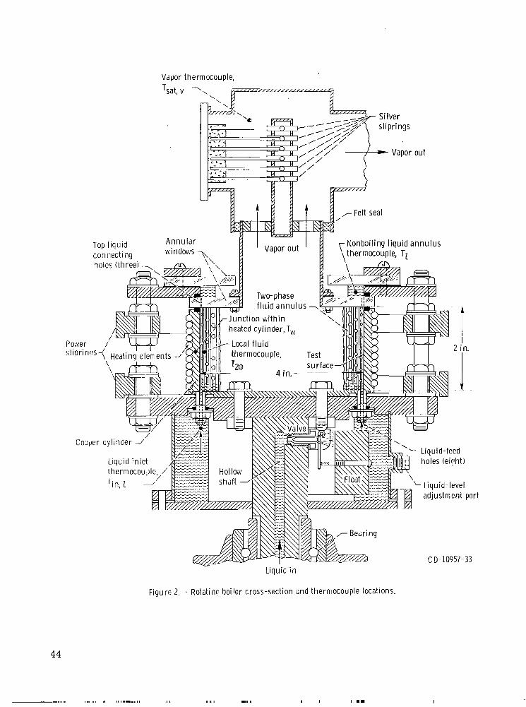
Top liquid con nect i ng
Vapor thermocouple,
Nonbailing liquid annulus \thermocouple, TZ
.. ..... I, 1 , 1 1 1 1 ..,.,,I
CD-10957-33
44
I
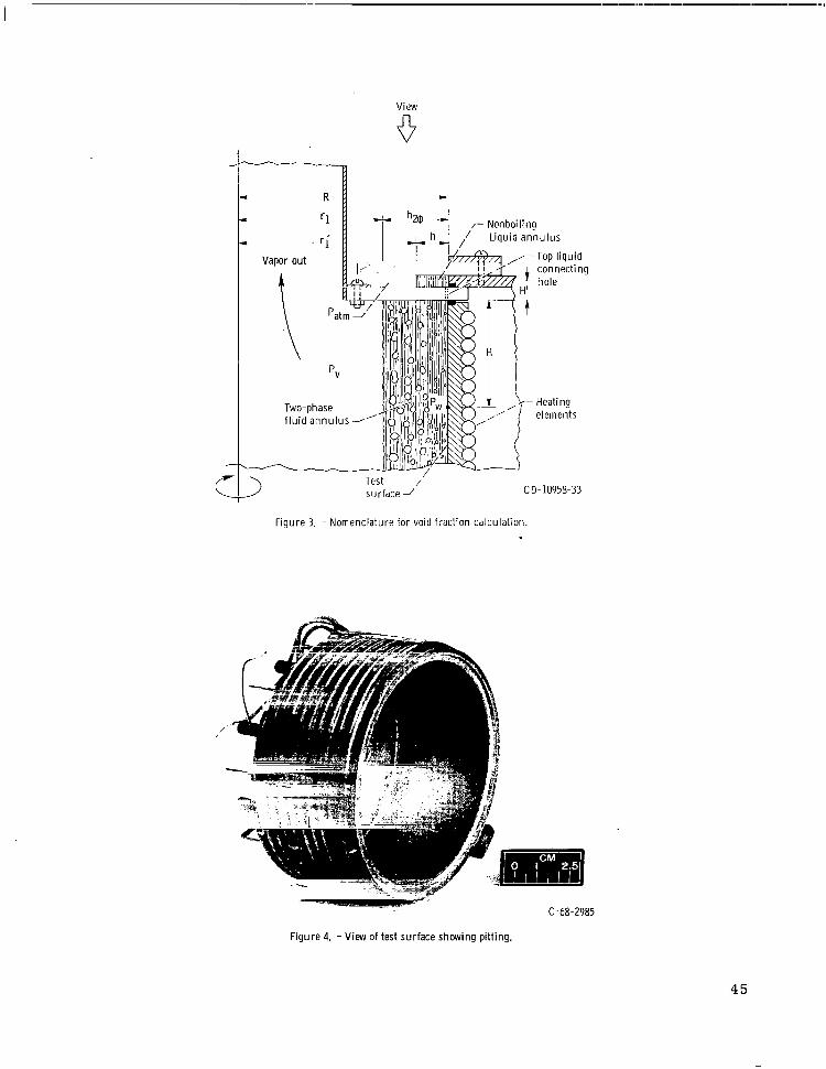
View
6
c
c
I R
I ‘1 r Nonboil ing ,/ Liquid annu lus
Test /’ surfdce J
CD-10958-33
Figure 3. - Nomenclature for void fraction calculat ion
c-68-2985
Figure 4. - View of test surface showing pitting.
45
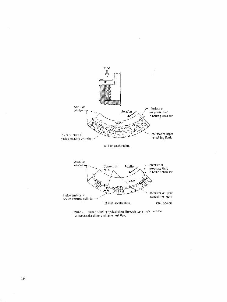
r Interface of A n n u l a r
in boi l ing chamber
‘Interface of upper Inside surface of hoated rotat ing cylinder-’
(a) Low acceleration.
Annu la r window
~~
,- Interface of two-phase f l u i d
4 in boi l ino chamber
Convection Rotation
/ /
Inside surface of heated rotat ing cy l inder-
(b) High acceleration. C 0-10959-33
Figure 5. - Sketch showina typical views th rough top annu la r window at two accelerations and same heat flux.
46

Heat flux, Liquid i n l e t R u n QlA subcooling,
Btu/(hr)(ftZ) MW/m2 ATsub "F K
A 465000 1.465 50 28 15 0 230000 .725 50 28 15 C 115000 .362 50 28 15 0 115000 .362 40 22 1
0 -230000 Z.725 -- -- }Ref. E, 1 g A\ 0 -115000 ~ 3 6 2 -- --
c- 0 ._ c " m, E 9
....
I I I
0 50 100 150 200 250 3000 35G 4CG Acceleration, g 's
F izure 15. -Average void i r a i t i o n oi two-;nase boi l ing annulus.
47
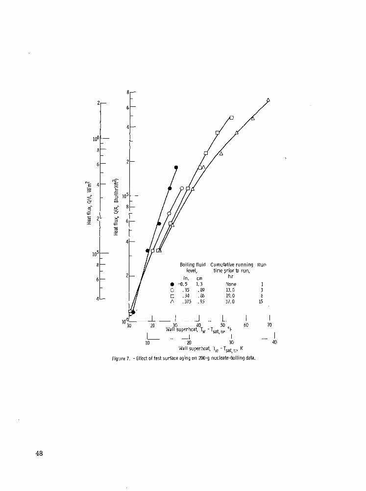
I
N-
Boiling fluid Cumulative running Run level, time prior to run,
0 -0.5 1.3 None 1 c .35 .s9 13. G 3 0 .34 .eo 19.0 6 n .375 .95 37.0 15
hr in. cm
I . I 20 3G 40 50 60 70
I I I I
- I Wall superhcat, Tw - T,at,w, "F
- 1 . - I - I 10 a 30 40
Wall su?erhcat, T,4, - Tsat,,,:, K
Figure 7. - Effect of test surface aging on 200-9 nucleate-boiling data.
48

Liauid in let Rotative F lu id level R u n subcooling, acceleration, in. cm
ATsubt g's O F K
0 65 36 25 0.27 0.69 2
10 15 20 25 30 35 Wall superheat, T, -TSat,,, "F
u 15 20
I 10
I 5
Wall superheat, T, - Tsat,w, K
Figure 8. - Effect of in let l iquid subcooling.
49

Liquiti level,
in. cm C. 0.625 1.59 c .fro0 1.27 0 .375 .952
G .219 .55i
0
(a) Eotative acceleration, XXI g's; run e.
c .3;5 C .55G c .125 C .063
104 15 25 3c 35
level,
cm 1. 27 ,952 ,635 .31: .159
J 40
Wall superheat, T, - T,,i,w, "F
10 15 x ;dall superheat, T, - Tsat,w. K
(bl Rotative acceleration, 25 g's: run 1C.
Figure 9. - Effect of l iqu id level (measured in top annulus1 o n boi l ing results. I,o in le t feed.
50
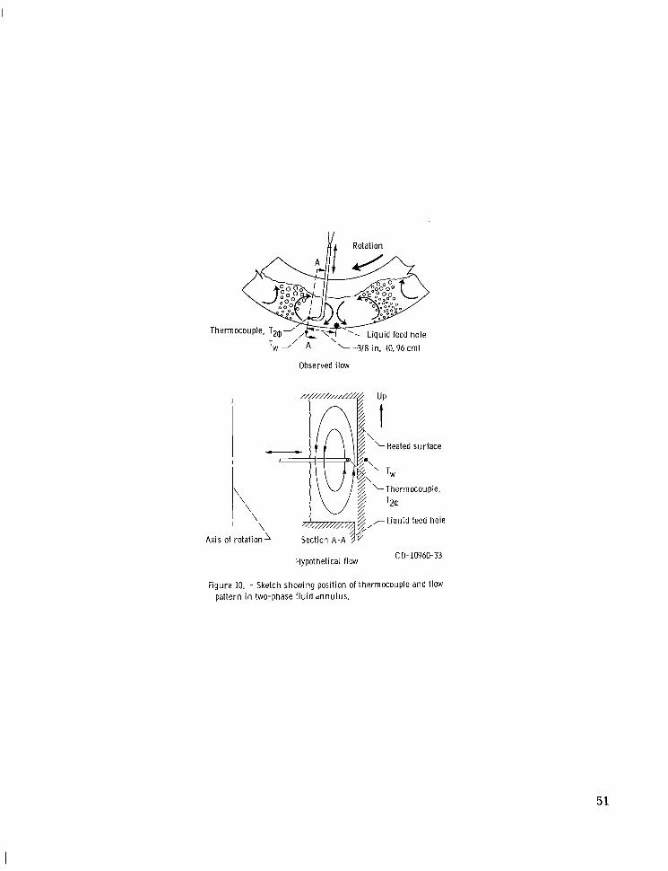
[A Rotation
- \ 'w -' A -318 in. (0.96cml
Observed flow
\ '\
\ ' \
Heated surface
Thermocouple,
-?!,,-Liquid feed hole
Axis of rotation' Section A-A
C D- 10960- 33 Hypothetical flow
Figure 10. - Sketch showing position of thermocouple and flow pattern in two-phase f l u i d dnnulus.
51
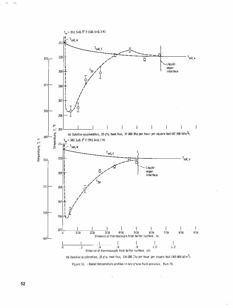
TvJ = 232.5t0.5" F (324.6+0.3 K)
372-
371
370
'lC
209
2 0 E -
207
- 206
Y 0
I-- 205
Tsat, v
-1
I I I I I I I I (a) Rotative acceleration, 25 g's; heat flux, 27 so0 Btu per h o u r per square foot (87 500 VUm2). L 2-
369 .2 = T, = 245.1iO. 2" F (391.6+0.1 K) 21 +-
pi F L
I 8/16 9/16
I 71 16
I 6/16
I 51 16
I I 1116 2/16 3/16 4/16
Distance of thermocouple from boiler surface, in.
I 1. 2
I 1.0
I . 8
1 . 6
I 0 . 2 . 4
Distance of thermocouple from boiler surface, cm
(2 ) Rotative acceleration, 25 g's; heat flux, 116 $00 :tu per hour per square foot (365 000 iiJ/m2).
Figure 11. - Radial temperature profiles in two-F'lase f l u i d annulus. Run 13.
52

220- f T, = 236. 2iO. 6' F (3%. 6k0.3 K ) I I 377-
I 375-
q, = 252.4~0. h,' F (395.650.2 K) I I -I-
+ 1 I T
L i r
Liquid-vapor
3701-
369 k
i T i I
-
M2 0 1/16 2/16 3/16 4/16 5/16 6/16 7/16 0 1\16 2/16 3/16 4/16 5/16 6/16 7/16
Distance of thermocouple f rom boiler surface, in.
1 0 . 2 . 4 . 6 . s 1.0 0 . 2 . 4 . 6 . 8 1.0
Distance of thermocouple from boiler surface, cm
(13 Rotative acceleration, 200 4's; heat flux, 27 100 Btu per h o u r per square Id) Rotative acceleration, 200 g's: heat flux, 115 OM) Btu per h o u r per square foot (85 200 W/m2). foot 1362 000 W/m2I.
Figure 11. -Concluded.
cn GJ

212
Heat f lux, Q ' h
Ct u I ( h r l l f t ii Vi lm * 0 26800 2ldO 0 115000 362000
2 16 3:16 4! 16 5:16 h 16 71 16 Distance of liquid-vapor interface from boi ler s d r f x e . iri.
200 L -. -L I. - .L- ~.. 1 .-. ... b - J 1 ' l L
-1 _ _ I - _ _ I . 2 . 4 . 6 . E 1.0 Distdnce of liquid-vapor interface from boiler surface, cm
Figtire 12. - Teiiiiiei-attire 1,4-inch (0.64-cml from boi ler surface measured a s f lu id ani i i i l t is thickness decreases. Run 14: rotative acceleration, 400 9's.
54
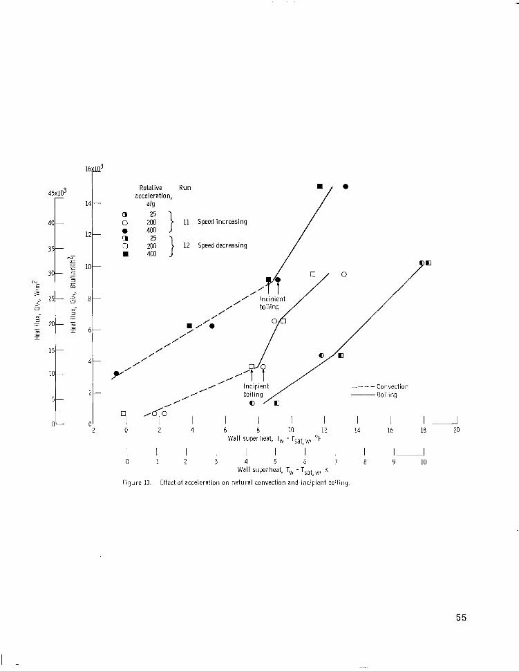
45x103
401
l. 0 5
Rotative R u n 0 acceleration,
a h a 0 ii } 11 Speed increasing 0 400 0 0 2; } 12 Speeddecreasing
400
0 2 4 6 8 10 12 14 16 ia
I I I I I I I I I 1 1 Wall superheat, T, - TSat, w, "F
C 1 2 3 4 5 6 7 a 9 10 Wall su>erheat, T, - Tsat,,y, K
Figure 13. - Effect of acceleration on natura l convection and inc ip ient boi l ing.
I 20
55

a b - O 0 400 } 11
Figure 14. -Correlation of natural-convection data at or near boiling incipience.
56

Rotative acceleration,
a h
-9- 50 0 100
--D-- a0 & 400
t I I'
I ' 70
I 45 50 60 65 55 I I I I
40 I
15 M 25 30 35 2
Wall superheat, T, - Tsat, ,, "F
35 40 I
30 I
25 I I
10 15 20 Wall superheat, T, -Tsat, ,, K
Figure 15. - Effect of acceleration o n nucleate boiling; two-phase f lu id level constant at 0.375 inch (0.95 cm). R u n 15; l iquid in le t subcooling, ~ 5 0 ~ F (28 K).
57

Rotative R u n
-Data band from
Schwartz (ref. 41;
4 6 8 1 0 iD 40 60 80 Wall superheat, T, - TSat, w, F
c 1 2 4 6 8 1 0 20 40
Wall superheat, T, - TSat, w, K
Figure 16. -Comparison o i nucleate-boil ing Gata a t h i g h accelerations.
58 NASA-Langley, 1971 - 33 E-6040

NATIONAL AERONAUTICS AND SPACE ADMINISTRAT ION
WASHINGTON, D. C. 20546 FIRST CLASS MAIL OFFICIAL BUSINESS
P E N A L T Y F O R P R I V A T E USE $300
POSTAGE AND FEES PAID ‘ATIONAL AERONAUTICS AN
SPACE ADMINISTRATION 07U 001 58 51 30s 71-10 00903
KIRTLAND AFB, NEkl MEXICO 87117 A I R F O R C E WEAPCNS L A R O R A T O R Y /ULOL/
4 T T E . L O U 6OWM.ANt CHIEF ,TECH- L I B R A R Y
POSTMASTER: If Undeliverable (Section 158 Posral Manual) Do Not Return
NASA
‘ T h e aeronantical and space activities of t he United States shall be conducted so as t o contribute . . . t o the expansion of hziiiian knowl- edge of phenomena in the atitlosphere and @ace. T h e Adniinistratioia ‘ shall provide fos the widest prncticable and appropriaje dissemination of infosiiintio?z concerning i ts activities and the resrilts thereof.’’
-NATIONAL AERONAUTICS AND SPACE ACT OF 1958
SCIENTIFIC AND TECHNICAL PUBLICATIONS
TECHNICAL REPORTS: Scientific and technical information considered important, complete, and a lasting contribution to existing knowledge.
TECHNICAL NOTES: Information less broad in scope but nevertheless of importance as a contribution to existing knowledge.
TECHNICAL MEMORANDUMS: Information receiving limited distribution because of preliminary data, security classifica- tion, or other reasons.
CONTRACTOR REPORTS: Scientific and technical information generated under a NASA contract or grant and considered an important contribution to existing knowledge.
TECHNICAL TRANSLATIONS: Information published in a foreign language considered to merit NASA distribution in English.
SPECIAL PUBLICATIONS: Information derived from or of value to NASA activities. Publications include conference proceedings, monographs, data compilations, handbooks, sourcebooks, and special bibliographies.
TECHNOLOGY UTILIZATION PUBLICATIONS: Information on technology used by NASA that may be of particular interest in commercial and other non-aerospace applications. Publications include Tech Briefs, Technology Utilization Reports and Technology Surveys.
Details on the availability of these publications may be obtained from:
SCIENTIFIC AND TECtiNlCAL INFORMATION OFFICE
NATIONAL AERONAUTICS AND SPACE ADMINISTRATION Washington, D.C. 90546
... . . . .. . . . . . .. . .