Effects of geometrical parameters on wrinkling of thin ... · Effects of geometrical parameters on...
7
Effects of geometrical parameters on wrinkling of thin-walled rectangular aluminum alloy wave-guide tubes in rotary-draw bending Tian Shan, Liu Yuli * , Yang He State Key Laboratory of Solidification Processing, Northwestern Polytechnical University, Xi’an 710072, China Received 31 August 2011; revised 6 December 2011; accepted 9 January 2012 Available online 16 January 2013 KEYWORDS Geometrical parameters; Inner flange wrinkling; Side wrinkling; Simulation; Thin-walled rectangular wave-guide tube; Rotary-draw bending Abstract Inner flange and side wrinkling often occur in rotary-draw bending process of rectangu- lar aluminum alloy wave-guide tubes, and the distribution and magnitude of wrinkling is related to geometrical parameters of the tubes. In order to study the effects of geometrical parameters on wrinkling of rectangular wave-guide tubes, a 3D-FE model for rotary-draw bending processes of thin-walled rectangular aluminum alloy wave-guide tubes was built based on the platform of ABA- QUS/Explicit, and its reliability was validated by experiments. Simulation and analysis of the influ- ence laws of geometrical parameters on the wave heights of inner flange and side wrinkling were then carried out. The results show that inner flange wrinkling is the main wrinkling way to rectan- gular wave-guide tubes in rotary-draw bending processes, but side wrinkling cannot be neglected because side wrinkling is 2/3 of inner flange wrinkling when b and h are smaller. Inner flange and side wrinkling increase with increasing b and h; the influence of b on side wrinkling is larger than that of h, while both b and h affect inner flange wrinkling greatly. Inner flange and side wrin- kling decrease with increasing R/h; the influence of h on inner flange and side wrinkling is larger than that of R. ª 2013 CSAA & BUAA. Production and hosting by Elsevier Ltd. 1. Introduction Thin-walled rectangular aluminum wave-guide tubes have been widely used in radar, communication, aerospace, and other fields, and rotary-draw bending is their main forming method. However, rotary-draw bending process is a complex forming process with many dies restriction, during which the tube forming quality can be seriously affected by wrinkling, cross-section distortion, etc. The wrinkling of a rectangular wave-guide tube in rotary-draw bending occurs not only in the compressive stress zone of its inner flange, but also in its side web because of uneven stress distribution. Many different cross-section dimensions of rectangular wave-guide tubes have been used in radar systems for the requirements of different transmission wavelengths, and there are also many different relative bending radii of rectangular wave-guide tubes for the requirements of different space layouts. The wrinkling wave height and distribution in inner flange and side web vary with different cross-section dimensions and bending radii of * Corresponding author. Tel.: +86 29 88460212 803. E-mail address: [email protected] (Y. Liu). Peer review under responsibility of Editorial Committe of CJA. Production and hosting by Elsevier Chinese Journal of Aeronautics, 2013,26(1): 242–248 Chinese Society of Aeronautics and Astronautics & Beihang University Chinese Journal of Aeronautics [email protected] www.sciencedirect.com 1000-9361 ª 2013 CSAA & BUAA. Production and hosting by Elsevier Ltd. http://dx.doi.org/10.1016/j.cja.2012.12.003 Open access under CC BY-NC-ND license. Open access under CC BY-NC-ND license.
Transcript of Effects of geometrical parameters on wrinkling of thin ... · Effects of geometrical parameters on...
Chinese Journal of Aeronautics, 2013,26(1): 242–248
Chinese Society of Aeronautics and Astronautics& Beihang University
Chinese Journal of Aeronautics
Effects of geometrical parameters on wrinkling of
thin-walled rectangular aluminum alloy wave-guide tubes
in rotary-draw bending
Tian Shan, Liu Yuli *, Yang He
State Key Laboratory of Solidification Processing, Northwestern Polytechnical University, Xi’an 710072, China
Received 31 August 2011; revised 6 December 2011; accepted 9 January 2012Available online 16 January 2013
*
E
Pe
10
ht
KEYWORDS
Geometrical parameters;
Inner flange wrinkling;
Side wrinkling;
Simulation;
Thin-walled rectangular
wave-guide tube;
Rotary-draw bending
Corresponding author. Tel.
-mail address: [email protected]
er review under responsibilit
Production an
00-9361 ª 2013 CSAA & BU
tp://dx.doi.org/10.1016/j.cja.2
: +86 29
u.cn (Y.
y of Edit
d hostin
AA. Pro
012.12.0
Abstract Inner flange and side wrinkling often occur in rotary-draw bending process of rectangu-
lar aluminum alloy wave-guide tubes, and the distribution and magnitude of wrinkling is related to
geometrical parameters of the tubes. In order to study the effects of geometrical parameters on
wrinkling of rectangular wave-guide tubes, a 3D-FE model for rotary-draw bending processes of
thin-walled rectangular aluminum alloy wave-guide tubes was built based on the platform of ABA-
QUS/Explicit, and its reliability was validated by experiments. Simulation and analysis of the influ-
ence laws of geometrical parameters on the wave heights of inner flange and side wrinkling were
then carried out. The results show that inner flange wrinkling is the main wrinkling way to rectan-
gular wave-guide tubes in rotary-draw bending processes, but side wrinkling cannot be neglected
because side wrinkling is 2/3 of inner flange wrinkling when b and h are smaller. Inner flange
and side wrinkling increase with increasing b and h; the influence of b on side wrinkling is larger
than that of h, while both b and h affect inner flange wrinkling greatly. Inner flange and side wrin-
kling decrease with increasing R/h; the influence of h on inner flange and side wrinkling is larger
than that of R.ª 2013 CSAA & BUAA. Production and hosting by Elsevier Ltd.
Open access under CC BY-NC-ND license.1. Introduction
Thin-walled rectangular aluminum wave-guide tubes havebeen widely used in radar, communication, aerospace, and
other fields, and rotary-draw bending is their main forming
88460212 803.
Liu).
orial Committe of CJA.
g by Elsevier
duction and hosting by Elsevier L
03
method. However, rotary-draw bending process is a complexforming process with many dies restriction, during which thetube forming quality can be seriously affected by wrinkling,
cross-section distortion, etc. The wrinkling of a rectangularwave-guide tube in rotary-draw bending occurs not only inthe compressive stress zone of its inner flange, but also in itsside web because of uneven stress distribution. Many different
cross-section dimensions of rectangular wave-guide tubes havebeen used in radar systems for the requirements of differenttransmission wavelengths, and there are also many different
relative bending radii of rectangular wave-guide tubes for therequirements of different space layouts. The wrinkling waveheight and distribution in inner flange and side web vary
with different cross-section dimensions and bending radii of
td. Open access under CC BY-NC-ND license.
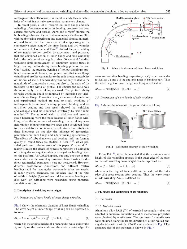
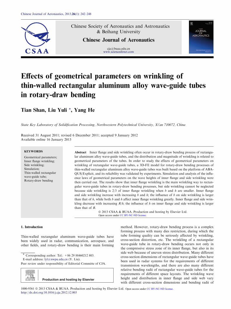
Fig. 1 Schematic diagram of inner flange wrinkling.
Fig. 2 Schematic diagram of side wrinkling.
Effects of geometrical parameters on wrinkling of thin-walled rectangular aluminum alloy wave-guide tubes 243
rectangular tubes. Therefore, it is useful to study the character-istics of wrinkling as tube geometrical parameters change.
In recent years, a lot of research on inner flange and side
wrinkling of rectangular tubes in bending processes has beencarried out home and abroad. Zarei and Kroger1 studied thehit bending behavior of square aluminum tubes hollow or filled
with bubble using experiment and numerical simulation meth-od, and found that there was one wrinkle appearing in thecompressive stress zone of the inner flange and two wrinkles
in the side web. Corona and Vaze2,3 studied the pure bendingof rectangular section profiles by experiment, and proposedthat the combined action of inner flange and side wrinklingled to the collapse of rectangular tubes. Okude et al.4 studied
wrinkling limit improvement of aluminum square tubes inlarge bending radius during draw bending process. Jia andGao5 studied the pressure bending of hollow aluminum pro-
files for automobile frames, and pointed out that inner flangewrinkling of profiles was similar to the ends pressure instabilityof thin-walled shells. The wrinkling was not only related to the
magnitude of compressive stress, but also to the ratio of thethickness to the width of profile. The smaller the ratio was,the more easily the wrinkling occurred. The profile’s ability
to resist wrinkling could be improved by increasing the thick-ness of inner flange. Theoretical analysis, numerical simulationand experimental method are used to study wrinkling ofrectangular tubes in draw bending, pressure bending, and ro-
tary-draw bending and their results showed that wrinklingand collapse could be eliminated effectively by using innermandrel.6–10 The ratio of width to thickness and material
strain hardening were the main reasons of inner flange wrin-kling; after the occurrence of wrinkling, the wrinkling wavedeformation in inner compressive stress zone developed faster
to the even deformation in outer tensile stress zone. Studies inthese literatures do not give the influence of geometricalparameters on inner flange and side wrinkling systematically.
The effects of tube diameters and bending radii on formingquality of round tubes are studied in Refs.11–13, which pro-vided guidance to the research of this paper. Zhao et al.14,15
mainly studied the effects of process parameters on wrinkling
of rectangular wave-guide tubes in rotary-draw bending basedon the platform ABAQUS/Explicit, but only one size of tubewas studied and the wrinkling variation characteristics for dif-
ferent geometrical parameters were not researched. However,different cross-section dimensions and different relativebending radii for rectangular wave-guide tubes are needed
in radar system. Therefore, the influence laws of the ratioof width to height (b/h) and neutral line relative bending ra-dius (R/h) on wrinkling were researched using numericalsimulation method.
2. Description of wrinkling wave height
2.1. Description of wave height of inner flange wrinkling
Fig. 1 shows the schematic diagram of inner flange wrinkling.
The wave height of inner flange wrinkling can be expressed asfollows:
Dhi ¼ h�ffiffiffiffiffiffiffiffiffiffiffiffiffiffiffiffiffiffiffiffiffiffiffiffiffiffiffiffiffiffiffiffiffijAiBij2 � jAiCij2
qði ¼ 0; 1; . . . ; jÞ ð1Þ
where h is the original height of a rectangular wave-guide tube;Ai and Bi are the center node and the node in outer edge of a
cross section after bending respectively; AiCi is perpendicularto BiCi at Ci; and j is the end grid node in bending part. Thusthe wave height of inner flange wrinkling is defined as:
Dhmax ¼ maxfjDhijg ði ¼ 0; 1; . . . ; jÞ ð2Þ
2.2. Description of wave height of side wrinkling
Fig. 2 shows the schematic diagram of side wrinkling.
From Ref. 16, it can be counted that the maximum waveheight of side wrinkling appears in the outer edge of the tube,so the side wrinkling wave height can be expressed as:
Dbi ¼ ðb� biÞ=2 ði ¼ 0; 1; . . . ; jÞ ð3Þ
where b is the original tube width; bi the width of the outeredge of a cross section after bending. Thus the wave heightof side wrinkling Dbmax is defined as:
Dbmax ¼ maxfjDbijg ði ¼ 0; 1; . . . ; jÞ ð4Þ
3. FE model and verification of its reliability
3.1. FE model
3.1.1. Material model
Aluminum alloy 3A21 (T4) of extruded rectangular tubes wasadopted in numerical simulation, and its mechanical properties
were obtained by tensile tests. The specimens for tensile testswere obtained along the length direction of a thin-walled rect-angular tube with a width of 24.86 mm, as shown in Fig. 3.Thegeometry size of the specimen is shown in Fig. 4.
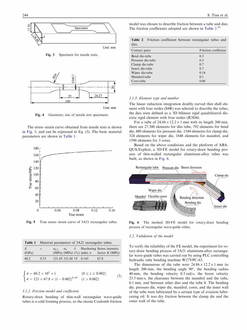
Fig. 4 Geometry size of tensile test specimens.
Table 2 Friction coefficient between rectangular tubes and
dies.
Contact pairs Friction coefficient
Bend die-tube 0.3
Pressure die-tube 0.3
Clamp die-tube 0.7
Insert die-tube 0.7
Wiper die-tube 0.14
Mandrel-tube 0.1
Core-tube 0.06
Fig. 3 Specimen for tensile tests.
244 S. Tian et al.
The stress–strain curve obtained from tensile tests is shownin Fig. 5, and can be expressed in Eq. (5). The basic material
parameters are shown in Table 1.
Fig. 6 The meshed 3D-FE model for rotary-draw bending
process of rectangular wave-guide tubes.
Fig. 5 True stress–strain curve of 3A21 rectangular tubes.
Table 1 Material parameters of 3A21 rectangular tubes.
E
(GPa)
m r0.2(MPa)
rb(MPa)
d(%)
Hardening
index n
Stress intensity
factor K (MPa)
60.2 0.33 121.45 151.68 19 0.145 67.8
�r ¼ 60:2� 103 � �e ð0 6 �e 6 0:002Þ�r ¼ 121þ 67:8� ð�e� 0:002Þ0:145 ð�e > 0:002Þ
(ð5Þ
3.1.2. Friction model and coefficient
Rotary-draw bending of thin-wall rectangular wave-guidetubes is a cold forming process, so the classic Coulomb friction
model was chosen to describe friction between a tube and dies.The friction coefficients adopted are shown in Table 2.16
3.1.3. Element type and number
The linear reduction integration doubly curved thin shell ele-ment with four nodes (S4R) was selected to describe the tubes;
the dies were defined as a 3D bilinear rigid quadrilateral dis-crete rigid element with four nodes (R3D4).
For a tube of 24.86 · 12.2 · 1 mm with its length 200 mm,there are 27,300 elements for this tube, 792 elements for bend
die, 480 elements for pressure die, 1544 elements for clamp die,324 elements for wiper die, 1848 elements for mandrel, and1590 elements for 3 cores.
Based on the above conditions and the platform of ABA-QUS/Explicit, a 3D-FE model for rotary-draw bending pro-cess of thin-walled rectangular aluminum-alloy tubes was
built, as shown in Fig. 6.
3.2. Validation of the model
To verify the reliability of the FE model, the experiment for ro-
tary-draw bending process of 3A21 aluminum-alloy rectangu-lar wave-guide tubes was carried out by using PLC controllinghydraulic tube bending machine W27YPC-63.
The dimensions of the tube were 24.86 · 12.2 · 1 mm itslength 200 mm, the bending angle 90�, the bending radius40 mm, the bending velocity 0.5 rad/s, the boost velocity
23.5 mm/s, the clearance between the mandrel and the tube,0.1 mm, and between other dies and the tube 0. The bendingdie, pressure die, wiper die, mandrel, cores, and the inner wall
of the tube were lubricated by a certain type of aviation lubri-cating oil. It was dry friction between the clamp die and theouter wall of the tube.
Effects of geometrical parameters on wrinkling of thin-walled rectangular aluminum alloy wave-guide tubes 245
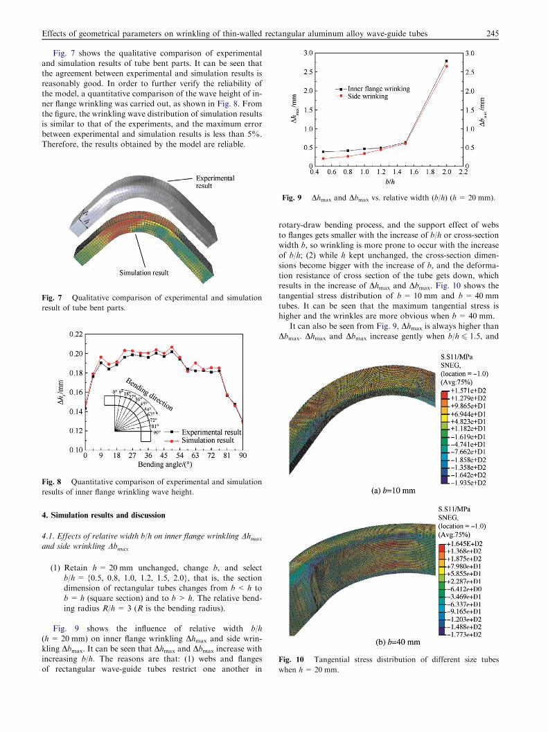
Fig. 7 shows the qualitative comparison of experimentaland simulation results of tube bent parts. It can be seen thatthe agreement between experimental and simulation results is
reasonably good. In order to further verify the reliability ofthe model, a quantitative comparison of the wave height of in-ner flange wrinkling was carried out, as shown in Fig. 8. From
the figure, the wrinkling wave distribution of simulation resultsis similar to that of the experiments, and the maximum errorbetween experimental and simulation results is less than 5%.
Therefore, the results obtained by the model are reliable.
Fig. 7 Qualitative comparison of experimental and simulation
result of tube bent parts.
Fig. 8 Quantitative comparison of experimental and simulation
results of inner flange wrinkling wave height.
Fig. 9 Dhmax and Dbmax vs. relative width (b/h) (h= 20 mm).
Fig. 10 Tangential stress distribution of different size tubes
when h= 20 mm.
4. Simulation results and discussion
4.1. Effects of relative width b/h on inner flange wrinkling Dhmax
and side wrinkling Dbmax
(1) Retain h= 20 mm unchanged, change b, and select
b/h= {0.5, 0.8, 1.0, 1.2, 1.5, 2.0}, that is, the sectiondimension of rectangular tubes changes from b< h tob= h (square section) and to b > h. The relative bend-
ing radius R/h = 3 (R is the bending radius).
Fig. 9 shows the influence of relative width b/h
(h= 20 mm) on inner flange wrinkling Dhmax and side wrin-kling Dbmax. It can be seen that Dhmax and Dbmax increase withincreasing b/h. The reasons are that: (1) webs and flanges
of rectangular wave-guide tubes restrict one another in
rotary-draw bending process, and the support effect of webs
to flanges gets smaller with the increase of b/h or cross-sectionwidth b, so wrinkling is more prone to occur with the increaseof b/h; (2) while h kept unchanged, the cross-section dimen-
sions become bigger with the increase of b, and the deforma-tion resistance of cross section of the tube gets down, whichresults in the increase of Dhmax and Dbmax. Fig. 10 shows the
tangential stress distribution of b= 10 mm and b = 40 mmtubes. It can be seen that the maximum tangential stress ishigher and the wrinkles are more obvious when b = 40 mm.
It can also be seen from Fig. 9, Dhmax is always higher thanDbmax. Dhmax and Dbmax increase gently when b/h 6 1.5, and
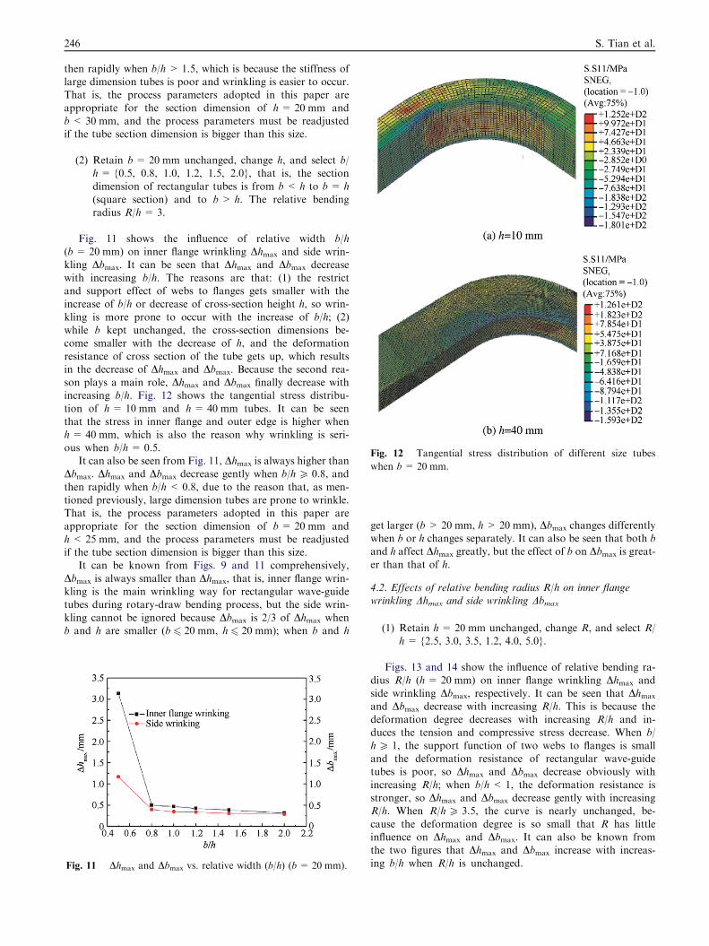
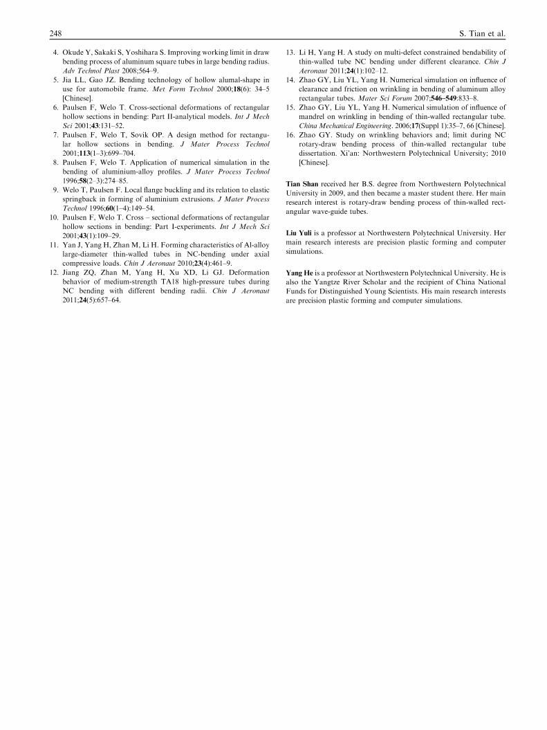
Fig. 12 Tangential stress distribution of different size tubes
when b= 20 mm.
246 S. Tian et al.
then rapidly when b/h> 1.5, which is because the stiffness oflarge dimension tubes is poor and wrinkling is easier to occur.That is, the process parameters adopted in this paper are
appropriate for the section dimension of h = 20 mm andb< 30 mm, and the process parameters must be readjustedif the tube section dimension is bigger than this size.
(2) Retain b= 20 mm unchanged, change h, and select b/h= {0.5, 0.8, 1.0, 1.2, 1.5, 2.0}, that is, the section
dimension of rectangular tubes is from b < h to b= h(square section) and to b > h. The relative bendingradius R/h = 3.
Fig. 11 shows the influence of relative width b/h(b = 20 mm) on inner flange wrinkling Dhmax and side wrin-kling Dbmax. It can be seen that Dhmax and Dbmax decrease
with increasing b/h. The reasons are that: (1) the restrictand support effect of webs to flanges gets smaller with theincrease of b/h or decrease of cross-section height h, so wrin-
kling is more prone to occur with the increase of b/h; (2)while b kept unchanged, the cross-section dimensions be-come smaller with the decrease of h, and the deformation
resistance of cross section of the tube gets up, which resultsin the decrease of Dhmax and Dbmax. Because the second rea-son plays a main role, Dhmax and Dbmax finally decrease withincreasing b/h. Fig. 12 shows the tangential stress distribu-
tion of h= 10 mm and h = 40 mm tubes. It can be seenthat the stress in inner flange and outer edge is higher whenh= 40 mm, which is also the reason why wrinkling is seri-
ous when b/h= 0.5.It can also be seen from Fig. 11, Dhmax is always higher than
Dbmax. Dhmax and Dbmax decrease gently when b/h P 0.8, and
then rapidly when b/h < 0.8, due to the reason that, as men-tioned previously, large dimension tubes are prone to wrinkle.That is, the process parameters adopted in this paper are
appropriate for the section dimension of b = 20 mm andh< 25 mm, and the process parameters must be readjustedif the tube section dimension is bigger than this size.
It can be known from Figs. 9 and 11 comprehensively,
Dbmax is always smaller than Dhmax, that is, inner flange wrin-kling is the main wrinkling way for rectangular wave-guidetubes during rotary-draw bending process, but the side wrin-
kling cannot be ignored because Dbmax is 2/3 of Dhmax whenb and h are smaller (b 6 20 mm, h 6 20 mm); when b and h
Fig. 11 Dhmax and Dbmax vs. relative width (b/h) (b= 20 mm).
get larger (b > 20 mm, h> 20 mm), Dbmax changes differentlywhen b or h changes separately. It can also be seen that both band h affect Dhmax greatly, but the effect of b on Dbmax is great-
er than that of h.
4.2. Effects of relative bending radius R/h on inner flangewrinkling Dhmax and side wrinkling Dbmax
(1) Retain h= 20 mm unchanged, change R, and select R/h = {2.5, 3.0, 3.5, 1.2, 4.0, 5.0}.
Figs. 13 and 14 show the influence of relative bending ra-dius R/h (h= 20 mm) on inner flange wrinkling Dhmax and
side wrinkling Dbmax, respectively. It can be seen that Dhmax
and Dbmax decrease with increasing R/h. This is because thedeformation degree decreases with increasing R/h and in-duces the tension and compressive stress decrease. When b/
h P 1, the support function of two webs to flanges is smalland the deformation resistance of rectangular wave-guidetubes is poor, so Dhmax and Dbmax decrease obviously with
increasing R/h; when b/h < 1, the deformation resistance isstronger, so Dhmax and Dbmax decrease gently with increasingR/h. When R/h P 3.5, the curve is nearly unchanged, be-
cause the deformation degree is so small that R has littleinfluence on Dhmax and Dbmax. It can also be known fromthe two figures that Dhmax and Dbmax increase with increas-
ing b/h when R/h is unchanged.
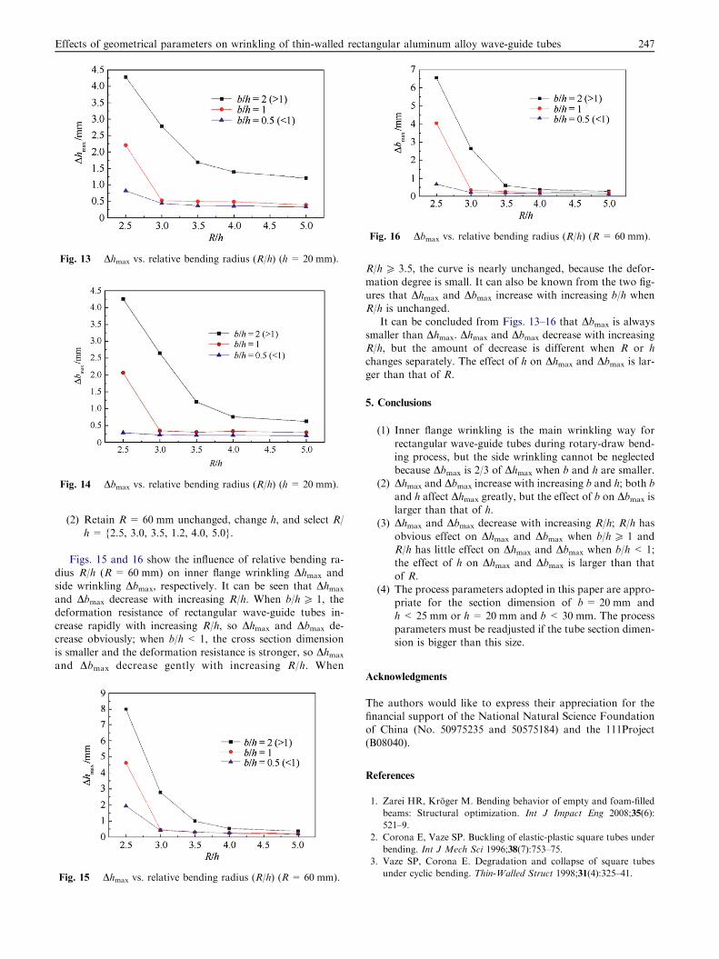
Fig. 13 Dhmax vs. relative bending radius (R/h) (h= 20 mm).
Fig. 14 Dbmax vs. relative bending radius (R/h) (h= 20 mm).
Fig. 16 Dbmax vs. relative bending radius (R/h) (R = 60 mm).
Effects of geometrical parameters on wrinkling of thin-walled rectangular aluminum alloy wave-guide tubes 247
(2) Retain R= 60 mm unchanged, change h, and select R/
h= {2.5, 3.0, 3.5, 1.2, 4.0, 5.0}.
Figs. 15 and 16 show the influence of relative bending ra-dius R/h (R= 60 mm) on inner flange wrinkling Dhmax and
side wrinkling Dbmax, respectively. It can be seen that Dhmax
and Dbmax decrease with increasing R/h. When b/h P 1, thedeformation resistance of rectangular wave-guide tubes in-
crease rapidly with increasing R/h, so Dhmax and Dbmax de-crease obviously; when b/h< 1, the cross section dimensionis smaller and the deformation resistance is stronger, so Dhmax
and Dbmax decrease gently with increasing R/h. When
Fig. 15 Dhmax vs. relative bending radius (R/h) (R = 60 mm).
R/h P 3.5, the curve is nearly unchanged, because the defor-mation degree is small. It can also be known from the two fig-
ures that Dhmax and Dbmax increase with increasing b/h whenR/h is unchanged.
It can be concluded from Figs. 13–16 that Dbmax is always
smaller than Dhmax. Dhmax and Dbmax decrease with increasingR/h, but the amount of decrease is different when R or hchanges separately. The effect of h on Dhmax and Dbmax is lar-ger than that of R.
5. Conclusions
(1) Inner flange wrinkling is the main wrinkling way for
rectangular wave-guide tubes during rotary-draw bend-ing process, but the side wrinkling cannot be neglectedbecause Dbmax is 2/3 of Dhmax when b and h are smaller.
(2) Dhmax and Dbmax increase with increasing b and h; both b
and h affect Dhmax greatly, but the effect of b on Dbmax islarger than that of h.
(3) Dhmax and Dbmax decrease with increasing R/h; R/h has
obvious effect on Dhmax and Dbmax when b/h P 1 andR/h has little effect on Dhmax and Dbmax when b/h < 1;the effect of h on Dhmax and Dbmax is larger than that
of R.(4) The process parameters adopted in this paper are appro-
priate for the section dimension of b= 20 mm and
h< 25 mm or h = 20 mm and b < 30 mm. The processparameters must be readjusted if the tube section dimen-sion is bigger than this size.
Acknowledgments
The authors would like to express their appreciation for thefinancial support of the National Natural Science Foundationof China (No. 50975235 and 50575184) and the 111Project
(B08040).
References
1. Zarei HR, Kroger M. Bending behavior of empty and foam-filled
beams: Structural optimization. Int J Impact Eng 2008;35(6):
521–9.
2. Corona E, Vaze SP. Buckling of elastic-plastic square tubes under
bending. Int J Mech Sci 1996;38(7):753–75.
3. Vaze SP, Corona E. Degradation and collapse of square tubes
under cyclic bending. Thin-Walled Struct 1998;31(4):325–41.
248 S. Tian et al.
4. Okude Y, Sakaki S, Yoshihara S. Improving working limit in draw
bending process of aluminum square tubes in large bending radius.
Adv Technol Plast 2008;564–9.
5. Jia LL, Gao JZ. Bending technology of hollow alumal-shape in
use for automobile frame. Met Form Technol 2000;18(6): 34–5
[Chinese].
6. Paulsen F, Welo T. Cross-sectional deformations of rectangular
hollow sections in bending: Part II-analytical models. Int J Mech
Sci 2001;43:131–52.
7. Paulsen F, Welo T, Sovik OP. A design method for rectangu-
lar hollow sections in bending. J Mater Process Technol
2001;113(1–3):699–704.
8. Paulsen F, Welo T. Application of numerical simulation in the
bending of aluminium-alloy profiles. J Mater Process Technol
1996;58(2–3):274–85.
9. Welo T, Paulsen F. Local flange buckling and its relation to elastic
springback in forming of aluminium extrusions. J Mater Process
Technol 1996;60(1–4):149–54.
10. Paulsen F, Welo T. Cross – sectional deformations of rectangular
hollow sections in bending: Part I-experiments. Int J Mech Sci
2001;43(1):109–29.
11. Yan J, Yang H, Zhan M, Li H. Forming characteristics of Al-alloy
large-diameter thin-walled tubes in NC-bending under axial
compressive loads. Chin J Aeronaut 2010;23(4):461–9.
12. Jiang ZQ, Zhan M, Yang H, Xu XD, Li GJ. Deformation
behavior of medium-strength TA18 high-pressure tubes during
NC bending with different bending radii. Chin J Aeronaut
2011;24(5):657–64.
13. Li H, Yang H. A study on multi-defect constrained bendability of
thin-walled tube NC bending under different clearance. Chin J
Aeronaut 2011;24(1):102–12.
14. Zhao GY, Liu YL, Yang H. Numerical simulation on influence of
clearance and friction on wrinkling in bending of aluminum alloy
rectangular tubes. Mater Sci Forum 2007;546–549:833–8.
15. Zhao GY, Liu YL, Yang H. Numerical simulation of influence of
mandrel on wrinkling in bending of thin-walled rectangular tube.
China Mechanical Engineering. 2006;17(Suppl 1):35–7, 66 [Chinese].
16. Zhao GY. Study on wrinkling behaviors and; limit during NC
rotary-draw bending process of thin-walled rectangular tube
dissertation. Xi’an: Northwestern Polytechnical University; 2010
[Chinese].
Tian Shan received her B.S. degree from Northwestern Polytechnical
University in 2009, and then became a master student there. Her main
research interest is rotary-draw bending process of thin-walled rect-
angular wave-guide tubes.
Liu Yuli is a professor at Northwestern Polytechnical University. Her
main research interests are precision plastic forming and computer
simulations.
Yang He is a professor at Northwestern Polytechnical University. He is
also the Yangtze River Scholar and the recipient of China National
Funds for Distinguished Young Scientists. His main research interests
are precision plastic forming and computer simulations.