Effects of Conformal Cooling Channels on Additively ...
58
Brigham Young University Brigham Young University BYU ScholarsArchive BYU ScholarsArchive Theses and Dissertations 2020-12-08 Effects of Conformal Cooling Channels on Additively Effects of Conformal Cooling Channels on Additively Manufactured Injection Molding Tooling Manufactured Injection Molding Tooling Tyler Blaine Whatcott Brigham Young University Follow this and additional works at: https://scholarsarchive.byu.edu/etd Part of the Engineering Commons BYU ScholarsArchive Citation BYU ScholarsArchive Citation Whatcott, Tyler Blaine, "Effects of Conformal Cooling Channels on Additively Manufactured Injection Molding Tooling" (2020). Theses and Dissertations. 8727. https://scholarsarchive.byu.edu/etd/8727 This Thesis is brought to you for free and open access by BYU ScholarsArchive. It has been accepted for inclusion in Theses and Dissertations by an authorized administrator of BYU ScholarsArchive. For more information, please contact [email protected], [email protected].
Transcript of Effects of Conformal Cooling Channels on Additively ...

Brigham Young University Brigham Young University
BYU ScholarsArchive BYU ScholarsArchive
Theses and Dissertations
2020-12-08
Effects of Conformal Cooling Channels on Additively Effects of Conformal Cooling Channels on Additively
Manufactured Injection Molding Tooling Manufactured Injection Molding Tooling
Tyler Blaine Whatcott Brigham Young University
Follow this and additional works at: https://scholarsarchive.byu.edu/etd
Part of the Engineering Commons
BYU ScholarsArchive Citation BYU ScholarsArchive Citation Whatcott, Tyler Blaine, "Effects of Conformal Cooling Channels on Additively Manufactured Injection Molding Tooling" (2020). Theses and Dissertations. 8727. https://scholarsarchive.byu.edu/etd/8727
This Thesis is brought to you for free and open access by BYU ScholarsArchive. It has been accepted for inclusion in Theses and Dissertations by an authorized administrator of BYU ScholarsArchive. For more information, please contact [email protected], [email protected].

Effects of Conformal Cooling Channels on Additively
Manufactured Injection Molding Tooling
Tyler Blaine Whatcott
A thesis submitted to the faculty of Brigham Young University
in partial fulfillment of the requirements for the degree of
Master of Science
Jason M. Weaver, Chair Andrew R. George Michael P. Miles
Department of Manufacturing Engineering
Brigham Young University
Copyright © 2020 Tyler Blaine Whatcott
All Rights Reserved

ABSTRACT
Effects of Conformal Cooling Channels on Additively Manufactured Injection Molding Tooling
Tyler Blaine Whatcott Department of Manufacturing Engineering, BYU
Master of Science
This study focuses on the cycle-averaged mold temperature of additively manufactured injection molding tooling and how it is affected by conformal cooling channels. This was done by producing a benchmark mold out of Digital ABS produced by Stratasys, an acrylic based photopolymer, which was then used to produce injection molded parts until tool failure. Another, more cost-effective material, High Temp Resin produced by Formlabs, another acrylic based photopolymer, was also tested but yielded very little success. Then the mold design was altered by adding conformal cooling channels and again tested by producing injection molded parts while tracking the mold temperature. This experimentation was then compared to an injection molding cooling channel model in order to validate the model for use with additively manufactured tooling with conformal cooling channels for use in injection molding.
The benchmark Digital ABS mold was able to produce 66 shots in the injection molding machine before complete mold failure. The Digital ABS mold had a cycle-averaged mold temperature of about 155°F. The High Temp Resin mold was able to produce 3 shots before complete mold failure. The High Temp Resin material is much more brittle, and the mold design did not take into account how brittle the material was. The Digital ABS mold with conformal cooling channels had a cycle-averaged mold temperature of 111°F. This is significantly lower than without cooling channels and has a high potential for improving tooling life. The cooling channel model predicted the cycle-averaged mold temperature to be 116°F. This proved to be a very good model and can be used as a design tool when choosing cooling channel geometry and position in additively manufactured tooling.
This research shows the potential that conformal cooling channels have to help improve additively manufactured tooling life for injection molding. As shown in other research done, the ability to maintain the mold below 120°F significantly improves the life of additively manufactured tooling. The results of this study demonstrate the effectiveness of conformal cooling channels in controlling mold temperature. It should be researched further, but the use of conformal cooling channels has the potential to produce more production or prototype parts with additively manufactured tooling for injection molding.
Keywords: additive manufacturing, injection molding, rapid prototyping, soft tooling, conformal cooling channels, tooling life

ACKNOWLEDGEMENTS
There are many people who had a great impact on this research and who helped it come
to fruition. I would like to thank my committee for giving insightful feedback, providing years of
wisdom from research they have done, and sharing how mine could be improved. They really
helped me focus on key aspects of the research which helped me to produce a better, more
fleshed out thesis. I would like to thank Dr. Jason Weaver for allowing me to plot my own course
and pursue a research topic that interested me.
I would like to thank the many people in the Utah additive manufacturing industry that
provided insight, support, direction, and resources. Specifically, I would like to acknowledge
James Barker from PADT who provided my first benchmark mold at no cost. James provided
motivation by checking up on me periodically and provided great feedback and many great
insights as well. He also connected me with Rulon Fischer and David Margetts from Ultradent in
South Jordan, UT who worked very closely with me to produce my final molds. Rulon helped
me work through some large roadblocks and was a great part of this research’s success.
Lastly, I would like to thank my family for their support all along the way. I would like to
thank my brother Russell Whatcott for always listening to my new ideas on how to overcome
obstacles and providing very insightful feedback from his 10+ years of experience in injection
molding. I couldn’t have done it without him. And most of all, I give my great love and
appreciation to my beautiful wife, Rosie Whatcott, for putting up with me for the past year and
half I as struggled past many hurdles and challenges. She offered support and motivation when it
seemed it would never workout or all come together. Rosie was with me all the way, through
failed experimentation, long nights, and longer days. She is my best friend and my greatest
support in all things.

iv
TABLE OF CONTENTS
LIST OF TABLES .......................................................................................................................... v
LIST OF FIGURES ....................................................................................................................... vi
1 Introduction ............................................................................................................................. 1
Background ...................................................................................................................... 1
Problem Statement ........................................................................................................... 3
2 Literature Review .................................................................................................................... 5
Additive Manufacturing ................................................................................................... 5
Rapid Tooling Injection Molding ..................................................................................... 5
Additive Tooling for Injection Molding........................................................................... 7
Methods for Improving Tooling Life ............................................................................. 10
Conformal Cooling Channels in Additive Tooling for Injection Molding .................... 12
Tooling Life Analysis..................................................................................................... 13
3 Methodology .......................................................................................................................... 15
Test Part and Mold Design ............................................................................................. 15
Support Tooling Design ................................................................................................. 22
Mold Production and Preparation .................................................................................. 23
Molding Process ............................................................................................................. 29
Insert Test Method and Analysis Method ...................................................................... 30
4 Results and Discussion .......................................................................................................... 32
Insert Failure .................................................................................................................. 32
Conformal Cooling Channel Performance ..................................................................... 40
5 Conclusions ........................................................................................................................... 45
References ..................................................................................................................................... 47

v
LIST OF TABLES
Table 3-1:Values Used for Calculation ......................................................................................... 19
Table 3-2: Molding Machine Process Parameters ........................................................................ 29
Table 4-1:Values Used for Calculation ......................................................................................... 43

vi
LIST OF FIGURES
Figure 2-1: Cost of RT vs Conventional Tooling in Manufacturing .............................................. 6
Figure 3-1: Test Part Top View .................................................................................................... 15
Figure 3-2: Test Part Bottom View ............................................................................................... 16
Figure 3-3: Mold Assembly .......................................................................................................... 16
Figure 3-4: A-Side Insert With Square Conformal Cooling Channels (Rev 1) ............................ 20
Figure 3-5: B-Side Insert With Square Conformal Cooling Channels (Rev 1) ............................ 20
Figure 3-6: A-Side Insert With Square Conformal Cooling Channels (Rev 2) ............................ 21
Figure 3-7: B-Side Insert With Square Conformal Cooling Channels (Rev 2) ............................ 21
Figure 3-8: Benchmark Mold Setup ............................................................................................. 22
Figure 3-9: Cooling Line Alterations ............................................................................................ 22
Figure 3-10: Sprue Bushing Flash Issues...................................................................................... 23
Figure 3-11: Digital ABS A-Side Mold Prepped for Testing ....................................................... 24
Figure 3-12: Digital ABS B-Side Mold Prepped for Testing ....................................................... 25
Figure 3-13: High Temp Resin A-Side Curing Damage .............................................................. 26
Figure 3-14: High Temp Resin B-Side Curing Damage ............................................................... 26
Figure 4-1: Digital ABS Benchmark Mold – Run 1 ..................................................................... 33
Figure 4-2: Digital ABS Benchmark Mold – Run 2 ..................................................................... 33
Figure 4-3: Digital ABS Benchmark Mold – Run 3 ..................................................................... 34
Figure 4-4: Digital ABS Benchmark Mold Initial Cracking ........................................................ 35
Figure 4-5: Digital ABS Benchmark Mold Cracking Just Prior to Failure .................................. 35
Figure 4-6: Digital ABS Benchmark Mold Final Failure ............................................................. 36
Figure 4-7: Digital ABS Benchmark Mold Gusset Feature Deformation .................................... 37

vii
Figure 4-8: Digital ABS Benchmark Mold B-Side After Failure ................................................. 37
Figure 4-9: High Temp Resin With Molded Part ......................................................................... 38
Figure 4-10:High Temp Resin Gusset Feature Failure ................................................................. 38
Figure 4-11: High Temp Resin A-Side Insert Crack .................................................................... 39
Figure 4-12: High Temp Resin A-Side Insert Failure .................................................................. 39
Figure 4-13: Digital ABS Mold With Conformal Cooling Channels Run 1 ................................ 41
Figure 4-14: Digital ABS Mold With Conformal Cooling Channels Run 2 ................................ 41
Figure 4-15: Mold With vs Mold Without Cooling Channels ...................................................... 42

1
1 INTRODUCTION
Background
Creating a mold for an injection molded (IM) part is a lengthy process and can take up to
6-8 weeks not including the time it takes to design the mold. Not only does it take a long time,
which translates into high cost, but making a mold out of tool steel or aluminum is expensive.
The high cost of making an injection molding tool can only be justified when the produced part
will be made in the thousands to hundreds of thousands of parts and then the return on
investment (ROI) on the mold typically comes after a year or more into production. This is due
to the low profit margins made from injection molded parts. This has forced injection molding to
become a process that is only used in very high volumes and rarely for any part that will only
need to be produced in the hundreds or low thousands.
The design iteration process with any mold design is slow and costly as well. There have
been many improvements in modeling and simulation software that allow for the design to be
thoroughly vetted before production but there are, at times, unforeseen issues in the design of an
IM mold. After the initial design and build, the mold is tested and validated and often, slight
changes need to be made to the mold to achieve results that meet the original design criteria.
When this happens during initial prototyping and design validation of a part, this can often slow
down the validation phase of design and delay product release.
2
Additive Manufacturing (AM) is a manufacturing process, commonly called 3D printing,
that creates a 3D part by depositing or curing a layer at a time of a polymer, resin, metal, paper,
or ceramic until a complete part is finished. The layers are combined through sintering, an
adhesive, or the deposited layer is hot enough for layer adhesion. This process is slow but the
price per part is the same for all volumes of production. AM is used very often for rapid
prototyping and has typically been used as a way to prove the form, fit, or function of a part
before it is mass produced by another process such as injection molding. Rarely is AM used to
produce an end use part because of the slow processing time and typically poor material
properties of the additively manufactured part. AM is not very cost effective for large volumes.
In the past two decades, many advances have been made in the field of AM and the
technology is being pushed to do things such as producing high quality, engineered, end use
parts but in low volumes. Between these two processes, injection molding and additive
manufacturing, there is a large gap between the volumes at which they are typically used. IM is
impractical in low volumes because of high tooling costs, and AM is impractical in high volumes
because of slow production speeds. In the middle lies the marriage of the two processes and a
viable solution to lower volume end use parts with better quality materials and faster cycle times.
Additively manufactured tooling for injection molding is a new method to cost effectively
produce anywhere from 50-500 parts [1, 2, 3, 4, 5].
This method can be used for product testing before the hard injection molding tool is
made. The mold can be printed using the same design of the hard tool, usually with only slight
modifications, and then test parts can be produced. If the AM mold is used for product testing
and validation, it can, at the same time, be used to test and refine the tool design as well. It will
help reduce the time it takes to produce a hard tool that can be used for production and in some

3
cases, can produce enough parts to meet the demands of low volume production and completely
replace the hard tool.
The advantage that AM has over traditional mold making processes is that there is a lot of
freedom in the design of the mold. Many internal features can be added very easily, and the
complexity of the design has little to no effect on the time of the build of the tool. This is the
exact opposite of traditional methods. The more complex that a hard tool is, the longer that it
takes to build. One example, conformal channels, inside of an AM tool saves on printing material
and in fact makes the build time faster and less expensive.
An AM injection molding tool can produce 50-500 parts and then fails due to cracks in
the mold from the high temperatures and pressures of injection molding [6, 5]. Research has
been done on what causes the failures and what causes the cracks to spread the fastest and it is
shown to be the temperature of the mold when a cycle is started [6]. If the temperature is too
high, the strength of the mold is reduced and causes cracks to propagate and the mold to fail [5].
With this knowledge of how the tools fail, the focus can now shift to discover how the AM IM
tooling life can be improved. With a longer production life for AM IM tooling, this technology
can be used more and more for low volume production and can enhance the product
development process. One proposed method of improving the life of the tool is adding conformal
cooling channels in the mold to keep the tool as cool as possible during processing [7]. This will
be the focus of this study.
Problem Statement
This research is being conducted in order to better understand the effects of conformal
cooling channels on the cycle-averaged mold temperature of an additively manufactured tool for
injection molding and whether or not it has the potential to significantly improve the life of the

4
tool. The AM processes that will be studied are stereolithography (SLA) (particularly the SLA
process used in Formlab’s Form 2 SLA printer) and Polyjet (developed by Stratasys). SLA is an
AM process that uses a UV laser to cure a photopolymer in a vat one layer at a time until a 3D
part is produced. Polyjet jets the photopolymer down onto a build platform (similar to an inkjet
printer) and cures each layer with a UV light until a 3D part is produced. The SLA process will
be compared to the more commonly used Polyjet method used in industry for additively
manufactured injection molding tooling. The main advantage of the SLA process over the
Polyjet process being the lower cost and therefore a more industry accessible process for
producing AM IM tooling. It is hoped that a less expensive material and process can be used for
AM IM tooling so that it is more available to smaller companies or early startup companies. The
Polyjet method will then be tested further beyond the SLA process, to see how the life of the tool
is affected by adding conformal cooling channels. The hypothesis is that by adding conformal
cooling channels to a Polyjet AM IM tool, the tool will have a significantly lower cycle-averaged
mold temperature than an AM IM tool without any cooling system and therefore have a longer
tool life. From the data that is collected from experimentation, the following questions are to be
answered:
1. How effectively do conformal cooling channels lower the cycle-averaged mold
temperature of a Polyjet AM IM tool?
2. Using a cooling channel heat transfer model, how well does the model predict the cycle-
averaged mold temperature and how can it be used for AM IM tooling design?
3. What are some general troubleshooting guidelines that could be provided to improve the
process to make it more streamline and profitable?

5
2 LITERATURE REVIEW
Additive Manufacturing
Over the past decade or so, a lot of attention has been placed on additive manufacturing
in hopes to improve it and drive down the cost of the process. Traditionally, additive
manufacturing has been used solely for producing prototypes of parts. These prototypes were
used to test the form, fit, or function of a design. This is a very important capability of additive
manufacturing, but research continued to explore more capabilities and applications. This point
of research has developed into a vast and continuously growing industry that has proven to
demonstrate more and more applications of this once novel technology [8].
One point of research is the use of photopolymers in additive manufacturing processes
such as Stereolithography (SLA) or polymer jetting. Photopolymers can be altered and
customized to create different mechanical properties [1]. The cured photopolymers can have a
range of properties and therefore a range of applications. There are soft and malleable polymers,
hard and brittle polymers, and some polymers that are designed for high temperature
applications. With this customization, SLA and polymer jetting have been used for some more
novel applications such as tooling for injection molding [2].
Rapid Tooling Injection Molding
Because of the high cost of building an IM tool made from tool steels using traditional
subtractive manufacturing, there has always been a drive to make faster and cheaper tooling for
6
injection molding. The high cost is sometimes prohibitive to small companies or products that
will only be produced in small quantities. Machining has traditionally been the go-to method for
making molds for injection molding so a common way to make cheaper molds, faster has been to
look to cheaper materials such as aluminum. Aluminum molds are often used for quick
turnaround, low volume production runs or for prototype runs, but even then, there is still room
for making molds faster and that cost less.
Rapid tooling (RT) in manufacturing is a point of research that seeks to improve the cost
and build time of tooling in order to improve the design process and bring products to market
faster and at a lower cost [9]. There are different types of RT, typically categorized into hard or
soft and direct or indirect. Direct tooling being a tool made either by machining or AM processes
that directly produces the mold. Indirect tooling being a master pattern made by machining or
AM processes and the mold produced from the master pattern, typically by casting. Each type of
RT has its common uses but, this paper, along with many others, will attempt to show how soft-
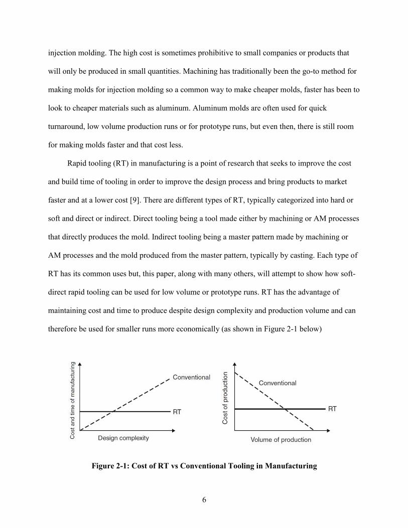
direct rapid tooling can be used for low volume or prototype runs. RT has the advantage of
maintaining cost and time to produce despite design complexity and production volume and can
therefore be used for smaller runs more economically (as shown in Figure 2-1 below)
Figure 2-1: Cost of RT vs Conventional Tooling in Manufacturing
7
One case study of RT was done with EP250 epoxy resin (25%) mixed with an aluminum
powder (75%) for a soft tool for injection molding [10]. This demonstrated that a mold made
from a polymer (epoxy) was able to function as a mold for injection molding and stand up to the
temperatures and pressures of injection molding. The lead time was cut in half and the price of
the soft tool was 25% that of a tool made in conventional tool steel. Approximately 500 parts
were molded off the tool which is significantly less than a steel mold can produce. Despite the
low number of parts produced, soft tooling still has its place in low volume production runs and
prototype runs due to quick tooling production time and lower cost. This type of RT would be
investigated further but it has its disadvantages as well. It is difficult to create the mold because it
requires several casting operations and is time consuming. Which is where AM tooling excels,
being very easy to produce high quality tooling by simply printing the mold.
Additive Tooling for Injection Molding
Rapid tooling for injection molding has been done with many different materials but soon
after additive manufacturing emerged, it became one of the primary methods for producing soft-
direct tooling for injection molding. It is much simpler to produce than other rapid tooling
production methods such as casting and produces higher quality molds as well. Research has
shown that the cost of tooling can be reduced by 82% and that the tooling production lead time
can be reduced by 66% by using AM for injection molding tooling [11]. The most common
methods used for producing AM IM tooling is SLA and polymer jetting. Both of these processes
use photopolymers which, “due to the fact that the network density of the photopolymer can be
varied to a large extent, the mechanical properties (strength, Young’s modulus) of the final
photopolymer can be tailored over a wide range” [2]. The mechanical properties of AM parts
produced by SLA and polymer jetting can be “tuned” for specific applications by the producers

8
of the photopolymers, which, makes them very attractive for harsh environments such as
injection molding (high temperatures and pressures).
Other processes that are commonly used in AM are fused deposition modeling (FDM),
selective laser sintering (SLS), and binder jetting. SLA and polymer jetting are more commonly
used over these processes because of their ease of use, their high-quality production capabilities
(high resolution), and the fact that they use the photopolymer materials that are so tunable. FDM
is comparatively low quality and the materials available can’t withstand the high temperatures of
IM. SLS and binder jetting are strong candidates and are used for AM IM tooling but mostly for
metal tooling [12]. This is a great option but is more costly and requires more post processing
than SLA and polymer jetting.
A very common material that is used for AM IM tooling is a photopolymer produced by
Stratasys called Digital ABS. This material has been heavily studied and compared to different
materials. The surface quality of parts produced has been studied and is shown to be able to
produce high quality parts. In the study done by Volpato, 50 parts were made before mold failure
and the parts produced were comparable to those made with a steel tool with only some slightly
different properties [4].
The company Stratasys has recognized the market for this material and has written several
white papers on the topic of using their Digital ABS material for AM tooling for injection
molding [13.] Their white paper gives guidelines and tips on how to successfully design and
print a mold. They give general guidelines for better results such as:
• using injection plastics that have a lower melt temperature (<570°F)
• small to medium sized parts (<10 in3)
• using injection molding machines with under 200 tons of clamping force

9
• increase draft angles to 5°
• enlarge all gates
• and other general guidelines
Their white paper features a large number of case studies with many different mold features
being incorporated into the Digital ABS molds, just as a normal steel mold. Features such as
ejection systems, cooling systems, and multiple inserts or side action pieces. They suggest
increasing the cooling time for the injection cycle and after ejection, to allow the surface of the
tool to cool to 120°F.
Two other materials that can be used and that are an even less expensive option compared
to Digital ABS are acrylic based photopolymers produced by Formlabs called “Clear Resin” and
“High Temp Resin”. In a white paper written by Formlabs on a case study of tooling made for
injection molding, they compare the two materials and discuss their capabilities [14]. The Clear
and High Temp resins have similar properties to Digital ABS but are slightly more brittle [3, 15,
16, 17]. The case study done by Formlabs was only done on a benchtop style injection molding
machine and they do not recommend using their molds with industrial injection molders. It is
worth noting though, that the molds can still produce up to 100 parts which, for some
applications may be the best option. No data has been given on the negative results of using this
material in an industrial injection molding machine.
More studies have been done to compare Digital ABS to P20 tool steel molds and have
found that parts that are produced from Digital ABS are comparable to those produced from P20
[18]. Simulation work has been done with AM tooling for reaction injection molding and has
been found to be a viable option for producing at least 200 parts and has the potential “to reduce
costs by up to 98.75%” [19]. One particular case study was done with Digital ABS and reported

10
producing more than 10,000 parts [20]. This is most likely attributed to the part design being
very simple, the insert being very small, and only one half of the insert was additively
manufactured, with the other half being a metal plate that could have taken the brunt of thermal
and mechanical stresses.
Methods for Improving Tooling Life
The most common reported causes of AM IM tool failure have been two major factors, the
injection pressure, and the temperature of the mold at the time of injection [3, 6, 21, 22]. The
focus of this paper is on the thermal failures of the molds and how to improve the longevity of
the tooling by better controlling the temperature of the mold. There have been many different
benefits found resulting from controlling the temperature of the tool. One study reports better
dimensional accuracy of parts produced by maintaining a cool mold [21]. Mechanical properties
of the AM IM insert are much better at lower temperatures, as well as uniform cooling in the part
and uniform shrinkage of the part [3].
Once research had demonstrated that AM tooling for injection molding was a viable and
cost effective method for producing prototypes and small volume parts, research continued to
push this technology forward to find ways to improve the life of the tooling. Davoudinejad
found, as mentioned previously, that the temperature of the mold had the greatest influence in the
life of the mold [6]. This study was done by conducting a DOE with packing time, packing
pressure, melt temperature of injected polymer, injection speed, mold temperature and cooling
time as the factors of the experiment. Simulations were done as well to show where the tool
would fail which were found to be the corners and side walls of cavities. The “hot spots” in the
simulation were where the tool failed in experimentation. Inserts that were allowed to cool

11
longer and that did not proceed with injection until the mold reached a temperature of 77°F
lasted the longest.
Some test materials were tested by Etesami with the heat deflection temperature of the
materials being the focus of the study [23]. Samples were placed in an oven and the deflection
and indentation depth of the samples were recorded and compared to the temperature in the oven.
This study showed that a possible way to improve mold performance is to add a chopped fiber to
the mold, either carbon fiber or glass. This may be problematic for most photopolymers because
it may interfere with the polymerization of the polymer but may be an option for other AM
processes and an area that could use further research.
Research that focused on the tool strength as affected by the temperature of the mold
showed that after allowing the tool to cool to 104°F-122°F before injection, the mold’s “strength
was still maintained and the low conductivity of the” mold “worked in favor of the process
initially” [5]. This research points out that by lowering the temperature of the mold before
injection, the chance of flexural failure is reduced. It is suggested that the tool be cooled by free
convection or air jet. It also suggests reducing the aspect ratio of mold features to reduce the risk
of flexural failure. As this is often not an option because of the design of the produced part,
controlling the temperature of the mold is the preferred solution.
Temperature control was the main focus of the research done by Schuh in 2020 [7]. Three
main methods were offered as means to controlling the temperature of AM tool. They are:
• Process features (such as cooling the surface of the mold with jet air between cycles)
• Mold features (such as cooling channels, especially conformal cooling channels)
• Insert features (such as additives in the AM material to control the thermal conductivity)

12
This study provides a selection model for which features should be incorporated into a mold
design. The most promising method for mold temperature control is internal conformal cooling
channels. It provides the most efficient way to remove heat from the AM insert and maintaining
the mold below temperatures that lead to failure.
Conformal Cooling Channels in Additive Tooling for Injection Molding
This paper will focus on the benefits of conformal cooling channels and how they improve
the life of AM tooling. Much research has been done on the subject and this paper will attempt to
expound on previous research done. Some early research done with conformal cooling channels
was done without the AM technology and was a good foundation for future research [24].
Copper pipes were bent to conformal shapes and then a soft RT insert was cast using an epoxy
resin and a master. This research pointed out the difficulties of the RT process and that
improvements still needed to be made.
A lot of work that has been done with conformal cooling has mostly been simulation work
[25, 26, 27]. This work is beneficial as it helps direct studies into new areas that have great
potential for success, e.g. porous conformal structures that allow for more uniform cooling of the
AM insert [26]. It also shows how the structure of the channels can be designed to minimize
structural strength loss and allow the channels to be even closer to the surface of the insert
cavities [27]. But as Shinde points out, this work only goes so far, and more work needs to be
done with actual experimentation to help solve issues that are sure to arise while implementing
these new technologies [25].
Another early study was done using the SLA AM process to compare the effectiveness of
different cooling channel geometries [28]. It was found that the most effective geometry for
cooling is a square channel that is approximately 1.5 x the width of the channel away from the

13
surface of the cavity of the mold. It was shown that by using this geometry of channels, the
temperature of the AM insert was reduced by up to 170°F as compared to an insert with no
cooling channels. Although a general rule was given for the depth of the channel below the
cavity surface, a more calculated approach was taken by other researchers that took into account
the thermal properties of the insert [12, 29, 30, 31, 32]. This calculated approach will be applied
here.
Work has previously been done on implementing cooling channels in a Digital ABS AM
insert but no detailed findings have been published [13]. Stratasys reports a 20% increase in tool
life but does not release much more information than this. The hope with this study is to verify
and provide data to the findings and to verify a model that can be used as a design tool for AM
IM tool design. It is hoped that by changing the geometry of the channels and precisely
calculating the correct position of the channels below the surface of the mold, a significantly
lower cycle-averaged mold temperature can be achieved. It is also the goal of this study to help
add to the body of knowledge of how to make a more rugged design and molding setup so that
future users will achieve better results.
Tooling Life Analysis
It is often difficult to determine the effectiveness of an improvement made to a process
without using statistically significant data. The best way to determine the effectiveness of the
addition of conformal cooling channels to a Digital ABS AM injection molding tool would be to
run a large sample size of inserts with and without channels and compare results. Without doing
this, other methods to determine the cooling channel’s effectiveness will need to be put into
place. In order to ensure that there are clear results for this study, the metrics that will be used to
determine success will be laid out here.

14
As used in almost all the studies cited in this paper, the metric used for the life of a tool is
the number of parts produced from the mold before catastrophic failure of the mold. This method
is a good metric because it shows how well the insert performs where it counts, which is
producing parts. This method will be applied to the benchmark mold that is used in the study (a
Digital ABS AM insert with no cooling channels). Because of difficulties in producing the mold
with conformal cooling channels (which will be discussed in greater detail later in this work), a
different method will be used to compare the improvements found from adding cooling channels.
The mold and cooling channel performance will be compared to the cooling channel models and
the cycle-averaged temperature will be the main metric to determine performance [30, 31, 32].
As discussed earlier, another common metric for the longevity of the mold is how well
the temperature of the mold can be controlled. In different articles, it is shown that if the
temperature of the mold can stay at or below 120°F at the time of injection, the life of the tool
will be increased significantly [5, 6, 13]. This will be used in the latter half of this study as a
metric to determine the effectiveness of conformal cooling channels. The ability of the channels
to control the cycle-averaged temperature of the insert and keep it as close to or below 120°F
will determine how well the channels are performing and will show how much of an
improvement they make on the life of the tool.

15
3 METHODOLOGY
Test Part and Mold Design
With the effectiveness of conformal cooling channels being the focus of this study, a part
that would most benefit from this feature was designed as the test part. Traditional tooling
doesn’t have the capability to create cooling channels in deep cavities and therefore can
sometimes have a difficult time controlling the temperature. A deep pocket part was designed so
that this could be tested. A simple box was designed with some simple corner gusset features
(see figures 3-1 and 3-2). This design is similar to what may be found for an electronics housing
or some similar application. Some finer detail was added to the bottom of the part as well to test
how well the finer detail molded. The part was molded using acrylonitrile butadiene styrene or
ABS (CYCOLAC FXS610SK). This was chosen because it has a higher injection temperature
than other commodity plastics and would heat up the mold faster and give data faster than
polypropylene or polyethylene. It is also a common plastic used for this type of application.
Figure 3-1: Test Part Top View

16
Figure 3-2: Test Part Bottom View
The mold was designed using the part design. Stratasys recommends not allowing the
nozzle of the injection molder to make direct contact with the AM insert so a sprue bushing was
added to the assembly to prevent this [13] (see mold setup in Figure 3-3). The mold design was a
simple direct sprue gate design. The downsides of this gate design will be discussed later on. The
mold was designed using guidelines form three different sources, Plastics Materials and
Processing [33], Injection Mold Design Engineering [34], and Polyjet For Injection Molding
Technical Application Guide [13].
Figure 3-3: Mold Assembly
17
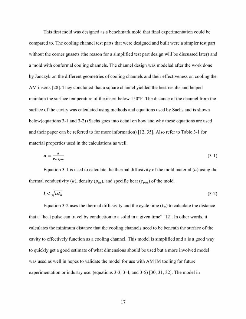
This first mold was designed as a benchmark mold that final experimentation could be
compared to. The cooling channel test parts that were designed and built were a simpler test part
without the corner gussets (the reason for a simplified test part design will be discussed later) and
a mold with conformal cooling channels. The channel design was modeled after the work done
by Janczyk on the different geometries of cooling channels and their effectiveness on cooling the
AM inserts [28]. They concluded that a square channel yielded the best results and helped
maintain the surface temperature of the insert below 150°F. The distance of the channel from the
surface of the cavity was calculated using methods and equations used by Sachs and is shown
below(equations 3-1 and 3-2) (Sachs goes into detail on how and why these equations are used
and their paper can be referred to for more information) [12, 35]. Also refer to Table 3-1 for
material properties used in the calculations as well.
𝒂𝒂 = 𝒌𝒌𝝆𝝆𝒎𝒎𝒄𝒄𝒑𝒑𝒎𝒎
(3-1)
Equation 3-1 is used to calculate the thermal diffusivity of the mold material (𝑎𝑎) using the
thermal conductivity (𝑘𝑘), density (𝜌𝜌𝑚𝑚), and specific heat (𝑐𝑐𝑝𝑝𝑚𝑚) of the mold.
𝒍𝒍 < �𝒂𝒂𝒕𝒕𝒌𝒌 (3-2)
Equation 3-2 uses the thermal diffusivity and the cycle time (𝑡𝑡𝑘𝑘) to calculate the distance
that a “heat pulse can travel by conduction to a solid in a given time” [12]. In other words, it
calculates the minimum distance that the cooling channels need to be beneath the surface of the
cavity to effectively function as a cooling channel. This model is simplified and a is a good way
to quickly get a good estimate of what dimensions should be used but a more involved model
was used as well in hopes to validate the model for use with AM IM tooling for future
experimentation or industry use. (equations 3-3, 3-4, and 3-5) [30, 31, 32]. The model in

18
equations 3-5 predicts the cycle-averaged mold temperature which will be a key metric for high
performance.
𝑹𝑹𝑹𝑹 = 𝒖𝒖 ∙ 𝒅𝒅𝒉𝒉𝒗𝒗
(3-3)
Equation 3-3 is used to calculate the Reynolds number (𝑅𝑅𝑅𝑅) of the coolant using the
hydraulic diameter of the channel (𝑑𝑑ℎ), the viscosity of the coolant (𝑣𝑣), and the velocity of the
coolant (𝑢𝑢).
𝜶𝜶 = .𝟎𝟎𝟎𝟎𝟎𝟎𝟎𝟎𝟎𝟎𝟎𝟎𝒅𝒅
∙ 𝑹𝑹𝑹𝑹𝟎𝟎.𝟖𝟖 (3-4)
Equation 3-4 is used to calculate the heat transfer coefficient (𝛼𝛼) between the mold and
cooling channels using the Reynolds number calculated in equation 3-3, the height of the cooling
channel (𝑑𝑑), and two known constants.
𝑻𝑻𝒎𝒎 = 𝑻𝑻𝒄𝒄 +𝝆𝝆𝒑𝒑∙𝒄𝒄𝒑𝒑𝒑𝒑∙
𝒔𝒔𝟐𝟐∙(𝟐𝟐∙𝒌𝒌∙𝒙𝒙+𝜶𝜶∙𝟒𝟒∙𝒅𝒅∙𝒍𝒍)∙�𝑻𝑻𝒑𝒑−𝑻𝑻𝑹𝑹�
𝜶𝜶∙𝟒𝟒∙𝒅𝒅∙𝒌𝒌∙𝒕𝒕𝒌𝒌 (3-5)
This model simplifies the problem by turning it into a 2D heat flow simulation. Using the
properties of the polymer melt (𝑐𝑐𝑝𝑝𝑝𝑝, 𝜌𝜌𝑝𝑝) and the thickness of the injected part (s), the thermal
mass of the polymer melt is taken in to account. Then the dimensions of the cooling channels (d)
and their position (𝑙𝑙) and pitch (𝑥𝑥) is used along with the thermal conductivity of the mold (𝑘𝑘) to
take into account the distance that the heat needs to travel before they reach the cooling channels.
The temperature of the melt at injection (𝑇𝑇𝑝𝑝) subtracted from the temperature of the mold at
ejection (𝑇𝑇𝑒𝑒) give the temperature that is removed from the system. The heat transfer coefficient
calculated in 3-4 is used with the size of the channel, thermal conductivity of the mold, and the
cycle time (𝑡𝑡𝑘𝑘) to take into account the amount of heat that can pulled away by the channels
during the cycle time. This is all added to the temperature of the coolant to calculate the cycle-
averaged mold temperature.

19
Table 3-1:Values Used for Calculation [3, 4, 6, 36, 37]
Property Value
Thermal Conductivity of Insert (𝑘𝑘) 𝑊𝑊𝑚𝑚𝑚𝑚
0.17
Density of Insert (𝜌𝜌𝑚𝑚) 𝑘𝑘𝑘𝑘𝑚𝑚3 1170
Specific Heat of Insert (𝑐𝑐𝑝𝑝𝑚𝑚) 𝐽𝐽𝑘𝑘𝑘𝑘𝑚𝑚
1030
Thermal Diffusivity of Insert (𝑎𝑎)𝑚𝑚2
𝑠𝑠 8.3 x 10⁻⁷
Cooling Channel Depth (𝑙𝑙) 𝑚𝑚, 𝑖𝑖𝑖𝑖 5.33 x 10⁻³, .21
Temperature of Coolant (𝑇𝑇𝑐𝑐) 𝐾𝐾, °𝐹𝐹 291, 64
Melt Polymer Density (𝜌𝜌𝑝𝑝) 𝑘𝑘𝑘𝑘𝑚𝑚3 1040
Specific Heat of Polymer (𝑐𝑐𝑝𝑝𝑝𝑝) 𝐽𝐽𝑘𝑘𝑘𝑘𝑚𝑚
1700
Part Wall Thickness (𝑠𝑠) 𝑚𝑚, 𝑖𝑖𝑖𝑖 2.16 x 10⁻³, .085
Cooling Channel Pitch (𝑥𝑥) 𝑚𝑚, 𝑖𝑖𝑖𝑖 1.69 x 10⁻², .665
Heat Transfer Coefficient (𝛼𝛼) 𝑊𝑊𝑚𝑚2𝑚𝑚
19114
Cooling Channel Height/Width (𝑑𝑑) 𝑚𝑚, 𝑖𝑖𝑖𝑖 5.84 x 10⁻³, .23
Polymer Melt Temperature �𝑇𝑇𝑝𝑝� 𝐾𝐾, °𝐹𝐹 480, 405
Ejection Temperature (𝑇𝑇𝑒𝑒)𝐾𝐾, °𝐹𝐹 379, 223
Cycle Time (𝑡𝑡𝑘𝑘) 𝑠𝑠𝑅𝑅𝑐𝑐 210
Cycle-Averaged Insert Temperature (𝑇𝑇𝑚𝑚)𝐾𝐾, °𝐹𝐹 319, 116
Reynolds Number (𝑅𝑅𝑅𝑅) 27455
Coolant Velocity (𝑢𝑢)𝑚𝑚𝑠𝑠
2.36
Hydraulic Diameter of Channel (𝑑𝑑ℎ) 𝑚𝑚 1.17 x 10⁻²
Kinematic Viscosity of Coolant (𝑣𝑣)𝑚𝑚2
𝑠𝑠 1.004 x 10⁻⁶
The model used from equations 3-3, 3-4, and 3-5 was not used for designing the mold but
was tested during experimentation to prove its effectiveness for AM IM molds with conformal
cooling channels. Using the simple model from equations 3-1 and 3-2, with a cycle time of 210
sec, the channel needed to be a minimum of .214” below the surface of the cavity of the insert.

20
This was rounded down to .21” and was the dimension used for designing the cooling channels
in the mold. The height of the square profile side was .23” this dimension was used out of
necessity, in order to be able to fit the cooling channel inside the insert without getting too close
to the outer wall or the inner cavity surface. The channel was centered between the outer wall
and inner surface. The thermocouple for the mold was placed .325” below the surface and
centered in the cavity. The original design for the cooling channels had a main line that entered
the insert, and then similar to a manifold, split off into 3 (A insert) and 4 (B insert) other lines
that circled the inset and returned to another outlet manifold as can be seen in figures 3-4 and 3-
5. The intent of this design was to allow for a shorter distance for the coolant to travel and
therefore, allow for more heat removal. This design proved to be difficult to remove support
material which will be discussed more later.
Figure 3-4: A-Side Insert With Square Conformal Cooling Channels (Rev 1)
Figure 3-5: B-Side Insert With Square Conformal Cooling Channels (Rev 1)

21
The improved design was a single line that spiraled around the insert and then exited the
insert in the same line (Figures 3-6 and 3-7). This allowed for simpler support material removal.
The coolant inlet was placed on the bottom of the mold, closest to the bottom surface of the
cavity so that the coolant would first run along the hottest part of the mold. Channel depth and
size with the new part design was consistent with the first. The part that was molded using the
insert with cooling channels was much simpler as mentioned before. The gusset feature on the
benchmark mold proved to be a failure mode that distracted from the real data that was being
researched and was removed.
Figure 3-6: A-Side Insert With Square Conformal Cooling Channels (Rev 2)
Figure 3-7: B-Side Insert With Square Conformal Cooling Channels (Rev 2)

22
Support Tooling Design
In order to help protect the inserts from the brunt of the clamping force of the injection
molding machine and to have a way to mount the inserts, support tooling frames were designed
and built. The design was very simple. The A-side was made to fit on the injection molding
machine that was used, a BOY 22-A. The B-side was made to fit in a standard M.U.D. base (see
Figures 3-8 and 3-9). The frames were made out of 6061 aluminum for its high machinability.
The frames were then altered after the benchmark mold was tested to accommodate for the
cooling channels and to provide a different mounting system for the inserts with conformal
cooling channels.
Figure 3-8: Benchmark Mold Setup
.
Figure 3-9: Cooling Line Alterations

23
Mold Production and Preparation
The benchmark molds were printed in 2 different materials, both the Digital ABS from
Stratasys and the High Temp Resin from Formlabs. The Digital ABS material specifically was a
combination of the materials RGD 515 and RGD 531 to produce the ivory color Digital ABS.
Support material used for the Stratasys print was SUP 705. The Digital ABS mold was printed
on an Objet polymer jetting system. The High Temp Resin specifically was FLHTAM02 from
Formlabs. The High Temp Resin mold was printed on a Form 2 SLA system.
The Stratasys mold was produced first as the benchmark mold for all tests conducted, it
being the most commonly studied material for this application. The mold was prepped by
removing the support material using a waterjet and some light sanding. After the support
material was removed, holes were drilled in the mold for mounting them to the support frames.
In order to install the sprue bushing, some sanding was required on the inside of the mold to
allow for a proper fit. After some initial trials to ensure proper function of the mold, a design
flaw was discovered in the mold design. There were no issues with the B-side design, but the A-
side had serious flash issues where the sprue bushing and insert mated (see Figure 3-10).
Figure 3-10: Sprue Bushing Flash Issues
24
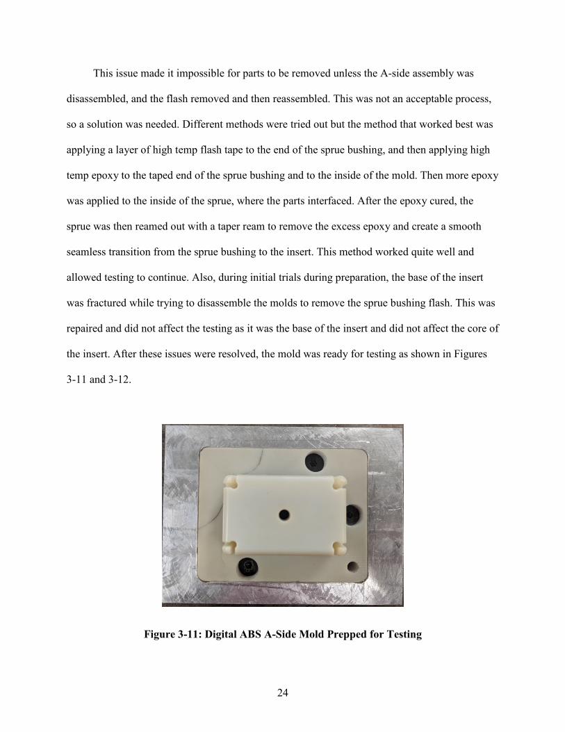
This issue made it impossible for parts to be removed unless the A-side assembly was
disassembled, and the flash removed and then reassembled. This was not an acceptable process,
so a solution was needed. Different methods were tried out but the method that worked best was
applying a layer of high temp flash tape to the end of the sprue bushing, and then applying high
temp epoxy to the taped end of the sprue bushing and to the inside of the mold. Then more epoxy
was applied to the inside of the sprue, where the parts interfaced. After the epoxy cured, the
sprue was then reamed out with a taper ream to remove the excess epoxy and create a smooth
seamless transition from the sprue bushing to the insert. This method worked quite well and
allowed testing to continue. Also, during initial trials during preparation, the base of the insert
was fractured while trying to disassemble the molds to remove the sprue bushing flash. This was
repaired and did not affect the testing as it was the base of the insert and did not affect the core of
the insert. After these issues were resolved, the mold was ready for testing as shown in Figures
3-11 and 3-12.
Figure 3-11: Digital ABS A-Side Mold Prepped for Testing

25
Figure 3-12: Digital ABS B-Side Mold Prepped for Testing
The High Temp Resin insert followed a slightly different method of preparation. After the
print was complete, the insert went through a series of cleaning and curing processes. The part
was put in an isopropyl bath to remove excess resin. It then was put in a heated UV cure at 80°C
for 120 minutes and then additionally post cured in an oven for 3 hours at 160°C. This was done
to achieve the highest heat deflection temperature (HDT) of 238°C @ .45 MPa. The hope was
that this higher temp cure would help the insert to last longer in the molding process. After
curing, the support material was removed mechanically by breaking off the supports and then
sanding the supported surfaces smooth.
After support removal, the A-side insert was sanded for proper fit of the sprue bushing,
similar to the Digital ABS insert, and then was epoxied in place as well. After the oven curing
process, some warping and cracking occurred to the inserts (Figure 3-13). It is likely that was
due to the print orientation and the large size of the part. The layers of the print likely caused the
part to cure unevenly and cause cracking and warpage. It also likely that removing the support
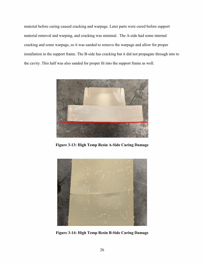
26
material before curing caused cracking and warpage. Later parts were cured before support
material removal and warping, and cracking was minimal. The A-side had some internal
cracking and some warpage, so it was sanded to remove the warpage and allow for proper
installation in the support frame. The B-side has cracking but it did not propagate through into to
the cavity. This half was also sanded for proper fit into the support frame as well.
Figure 3-13: High Temp Resin A-Side Curing Damage
Figure 3-14: High Temp Resin B-Side Curing Damage

27
After initial testing to ensure proper function of the High Temp Resin inserts, the part
very quickly failed. The results of the test will be discussed in more detail later but, in brief, the
surface finish of the High Temp Resin was very poor in comparison to the Digital ABS insert
which made the molded part removal very difficult. While attempting to remove the part, the
gusset features broke off and rendered the A-side insert unusable. This same gusset feature on
the Digital ABS mold also proved to be a failure mode. Although the Digital ABS mold features
did not break. They would bend outward due to the heat and pressure of injection. Because this
was a common failure mode, it was decided that this feature would be removed for future inserts
as it was not the focus of the study and could potentially cause premature failure of the insert.
Despite it being removed for future testing, it is worth noting the capabilities of the Digital ABS
material for being able to mold so many parts with this feature still present. After this initial part
failure, the A-side insert was re-printed without the gusset features and then prepared for test in
the same manner as described above but this time, the surface of the A-side core insert was
sanded to a smooth finish for easier part removal.
The Digital ABS inserts with conformal cooling channels were then printed. They were
printed with the same Digital ABS materials as mentioned above. The Rev 1 inserts were printed
first. The support material on the exterior of the inserts were removed first and then the internal
support material that created the cooling channels was then attempted to be removed. What could
be removed with a water jet, was easily removed but deep inside the channels, the water jet was
not strong enough to remove the material. The main issue with this was that when the parts were
requested to be printed, the assumption was that the soluble support material, SUP 706 was
going to be used for the print and that the support material removal would be a simple process. It
was, however, printed with SUP 705 which only slightly softens when soaked in a sodium

28
hydroxide solution unlike SUP 706 which is much easier to remove after being soaked in a
similar solution. Because of the design of the channels, there was no way that the support
material could be removed without damaging the mold. The manifold type design made it
extremely difficult.
After it was determined that the support material could not be removed, the Rev 2 mold
was designed and then printed. The printing supplier did not have SUP 706 so the hope was that
with the single channel printed with the same SUP 705 that the material could be removed with a
long wire or cable by pushing it through the channel. The Rev 2 mold was then printed, and the
support material was attempted to be removed. Because the channel was a single channel and
much longer than the Rev 1 mold, a wire could not be pushed all the way through the channel to
remove the support material. Other attempts at soaking the part in a heated sodium hydroxide
bath for extended periods of time with good circulation helped to soften the support material but
the material was still not able to be removed.
With limited resources, it was resolved that getting at least the B-side of the mold to have
channels would be sufficient to get data for testing. The B-side insert had an exterior wall that
could be drilled into and allow for easier access to the channel so that the support material could
be removed. A series of holes were drilled on the outside of the B-side insert, the support
material was removed, and then the holes were blocked up with set screws and RTV silicone.
Although this was not the ideal setup for the tests to be conducted, it would still allow for data to
be collected on the effectiveness of the channels at controlling the temperature of the insert and
could give a good indication at how it could potentially improve the life of the tool. It can be said
with a high degree of confidence that the support material could be removed with much more
ease if it were originally printed with SUP 706.

29
Molding Process
A BOY 22A injection molding machine was used for all experimentation. For all
experiments ran, the molder was run on a semi-automatic cycle (the machine would stop after
opening the mold so that the injected part could be removed manually and once the safety gate
was closed, the machine would continue its cycle). As recommended by Stratasys, the machine
was run on lower settings for temperatures, pressures, and speeds [13]. The following process
parameters were used for all experimentation (Table 3-2).
Table 3-2: Molding Machine Process Parameters
Process Parameter Setting
Injection Speed 5% of max Injection Pressure 200 PSI Injection Time 5 sec Holding Time 5 sec Holding Pressure 80 PSI Screw Retraction Distance 3.1 in Screw Rotation Speed 14.8 % of max Screw Plasticizing Pressure 50 PSI Cooling Time 90 sec Nozzle Temperature 405°F Front Barrel Temperature 401°F Front Middle Barrel Temperature 393°F Rear Middle Barrel Temperature 375°F Rear Barrel Temperature 365°F Mold Clamping Pressure 200 PSI
The ABS polymer was placed in a dryer at 170°F and then vacuum fed into the hopper.
The cooling system was run through a MOKON temperature control unit. The unit was set to
cool to 62°F. The inlet coolant was hooked up to the bottom line that was closest to the bottom

30
of the cavity so that the coolest water would contact the hottest part of the mold. The basic steps
that were followed while running the molding machine was as follows: spray the mold surface
with mold release, close the safety gate, press start, mold closes, screw advances and injects the
polymer melt, the screw rotates and retracts, the part cools, the mold opens, the safety gate is
opened, and the part is removed. This process was followed for all tests. At times, there was
some difficulties with the molds and there were occasional pauses between cycles to address
issues and therefore, the average cycle time was 210 seconds.
Insert Test Method and Analysis Method
The method used to test the inserts was simple and straight forward. The first benchmark
Digital ABS mold was run until failure while collecting temperature data from the insert. Due to
time constraints, this first test was done in 3 separate runs. The purpose of this test was to set a
baseline from which all other tests could be compared. The High Temp Resin inserts were run
until failure as well. The final tests that were run were also until failure, but the number of shots
run on the insert was not a metric for performance of the insert. This was not a metric for
performance since only one half of the mold was being tested. The A-side insert was not cooled
and therefore failed faster than if it had been cooled. The intent of the final cooling tests was to
collect data on how the conformal cooling channels performed and to determine the actual cycle-
averaged mold temperature of the insert being tested [30, 31, 32].
The definition of insert failure was the point at which no more parts could be made with
the insert. This was quite obvious in all cases and was not difficult to determine. The number of
shots that any insert could produce was not a metric that determined success or failure of the
insert but provided a quick and simple way to compare between materials. It was not used as a
metric to determine the results of this study.

31
The method used for testing the inserts was modeled after work done by Natti [32], Sachs
[12], and Davoudinejad [6]. The models that were used to design the cooling channels were the
key metric of performance of the inserts and the main insight into how well the conformal
cooling channels improved the life of the insert. The intent was to create a design based off of a
model and then to test the model and determine how well the model can inform the design
process. The hope was that the model would give a close representation of how the insert would
actually perform.
Another key metric was the cycle-averaged temperature of the mold. As stated previously
in this paper, a key metric to measure cooling channel performance is how well the insert can
stay at or below 120°F, which has been shown to significantly improve the life of an AM IM tool
[5, 6, 13]. When the mold stays at a cooler temperature, there is less risk of the mold being
damaged and less risk of a flexural failure [5].

32
4 RESULTS AND DISCUSSION
Insert Failure
As mentioned earlier, insert failure is a common metric used for the performance of an AM
IM tooling. This method will be used for demonstrating the performance of the benchmark
Digital ABS mold and the High Temp Resin molds. The number of shots that the insert was able
to successfully receive before catastrophic failure was the metric used to compare the initial
molds. The first mold, made from Digital ABS, performed well and was able to produce 66 shots
before catastrophic failure. The High Temp Resin mold was able to produce 3 shots before
catastrophic failure.
The mold ran at an average temperature of 138°F with a peak temperature of 185°F. The
mold took approximately 30 minutes to heat up to a more stable temperature. Once heated up,
the mold had an average temperature of about 155°F. Because of design flaws with the sprue
bushing, there were interruptions in the molding process and the recorded data was somewhat
lacking. Much more consistent and accurate data could potentially be recorded with a different
sprue/runner/gate design as it would allow for more consistent molding and the part would be
much easier to remove. There are breaks in the cycles because issues had to be addressed while
operating (mostly issues with the sprue bushing) which caused long cycle times and allowed the
mold to cool more than desired. Below is the data from the 3 runs of the temperature of the insert
over time (Figures 4-1, 4-2, and 4-3).

33
Figure 4-1: Digital ABS Benchmark Mold – Run 1
Figure 4-2: Digital ABS Benchmark Mold – Run 2
80
100
120
140
160
180
0 10 20 30 40 50 60 70 80 90 100
Tem
pera
ture
(°F)
Time (min)
80
90
100
110
120
130
140
150
160
170
180
190
0 10 20 30 40 50 60 70 80 90 100 110 120 130 140 150 160 170
Tem
pera
ture
(°F)
Time (min)

34
Figure 4-3: Digital ABS Benchmark Mold – Run 3
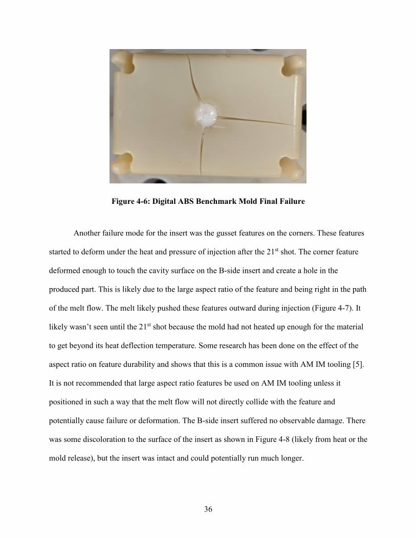
The final failure of the mold was a large crack that developed starting at the sprue and
propagated outward from there. The crack became so long and deep that the polymer that entered
the crack could no longer be removed. The crack initiated on the 31st shot during the 3rd run and
continued to grow from there until the 66th shot and complete failure. It is believed that because
of the design of the mold, the injection molding machine nozzle was pushing on the sprue
bushing with enough force that the mold material between the end of the sprue bushing and the
surface of the core fractured during injection when the pressure and heat were greatest (Figures
4-4, 4-5, and 4-6).
This issue is one of the main issues with the sprue gate design of this insert. Evidence
suggests that the poor design was the main cause of the insert failure. It also was the cause for
poor data collection because of the flash that would develop between the end of the sprue
80
90
100
110
120
130
140
150
160
170
180
190
0 20 40 60 80 100 120 140 160 180 200 220 240
Tem
pera
ture
(°F)
Time (min)

35
bushing and the insert. It is believed that if the sprue bushing was to the side of the core, and the
polymer melt was injected through the sprue, to a runner, and into the part through an edge gate,
the insert would have had much better success. This is an issue that could be researched further,
the best sprue, runner, and gate design for AM IM tooling.
Figure 4-4: Digital ABS Benchmark Mold Initial Cracking
Figure 4-5: Digital ABS Benchmark Mold Cracking Just Prior to Failure
36
Figure 4-6: Digital ABS Benchmark Mold Final Failure
Another failure mode for the insert was the gusset features on the corners. These features
started to deform under the heat and pressure of injection after the 21st shot. The corner feature
deformed enough to touch the cavity surface on the B-side insert and create a hole in the
produced part. This is likely due to the large aspect ratio of the feature and being right in the path
of the melt flow. The melt likely pushed these features outward during injection (Figure 4-7). It
likely wasn’t seen until the 21st shot because the mold had not heated up enough for the material
to get beyond its heat deflection temperature. Some research has been done on the effect of the
aspect ratio on feature durability and shows that this is a common issue with AM IM tooling [5].
It is not recommended that large aspect ratio features be used on AM IM tooling unless it
positioned in such a way that the melt flow will not directly collide with the feature and
potentially cause failure or deformation. The B-side insert suffered no observable damage. There
was some discoloration to the surface of the insert as shown in Figure 4-8 (likely from heat or the
mold release), but the insert was intact and could potentially run much longer.

37
Figure 4-7: Digital ABS Benchmark Mold Gusset Feature Deformation
Figure 4-8: Digital ABS Benchmark Mold B-Side After Failure
The High Temp Resin inserts had much lower performance than the Digital ABS inserts.
The High Temp Resin inserts experienced the same basic failure modes as the Digital ABS
inserts but failed much faster due to the material properties of the inserts. The High Temp Resin

38
is much more brittle and a less tough material. The first High Temp Resin mold was the same
design as the Digital ABS benchmark mold with the same gusset features and sprue bushing
design. The sprue bushing issue was resolved in the same way as the Digital ABS mold. The
High Temp Resin mold failed on the first shot. The part could not be removed from the mold.
The poor surface finish of the mold made it impossible to remove the part without breaking the
gusset features on the mold (Figures 4-9 and 4-10).
Figure 4-9: High Temp Resin With Molded Part
Figure 4-10:High Temp Resin Gusset Feature Failure
39
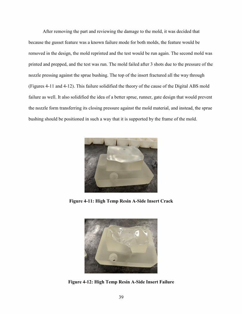
After removing the part and reviewing the damage to the mold, it was decided that
because the gusset feature was a known failure mode for both molds, the feature would be
removed in the design, the mold reprinted and the test would be run again. The second mold was
printed and prepped, and the test was run. The mold failed after 3 shots due to the pressure of the
nozzle pressing against the sprue bushing. The top of the insert fractured all the way through
(Figures 4-11 and 4-12). This failure solidified the theory of the cause of the Digital ABS mold
failure as well. It also solidified the idea of a better sprue, runner, gate design that would prevent
the nozzle form transferring its closing pressure against the mold material, and instead, the sprue
bushing should be positioned in such a way that it is supported by the frame of the mold.
Figure 4-11: High Temp Resin A-Side Insert Crack
Figure 4-12: High Temp Resin A-Side Insert Failure

40
It is believed that if a mold made from High Temp Resin were properly designed and
properly supported, this material could have great potential for success. A disadvantage of this is
that it could only be used for simple parts that don’t have features with large aspect ratios. These
features would very likely break simply from the injection pressure. But for the small use case of
simple parts and a well-designed mold, this material could be a suitable option. Further research
is needed on the actual potential of this material. Another material from Formlabs that could be
researched further is their Clear Resin which has similar properties to Stratasys’ Digital ABS.
Conformal Cooling Channel Performance
The data collected from the tests on the Digital ABS molds with conformal cooling
channels showed a lower temperature of the inserts and did so to a level that, according to
research, suggests great potential to significantly improve the life of the AM IM tool. On
average, the insert temperature was 111°F which is about 44°F cooler than the mold without
cooling channels (see Figures 4-13, 4-14, and 4-15). Research has shown that AM IM tooling
that can be kept below 120°F will significantly improve the life of the tool [5, 6, 13]. This test
was not done until failure, nor was a large sample size of inserts printed and tested, but with
more resources, this would be further research that would help confirm these findings, especially
for the Digital ABS material. Had there not been issues with the incorrect support material in the
cooling channels as discussed in the methodology, this mold would have been run to failure. The
temperature of the coolant entering the mold and exiting the mold was also recorded but didn’t
give consistent enough data for analysis. The coolant data is still displayed in the graph. It is
interesting to note how much the exiting coolant fluctuates during the molding process.

41
Figure 4-13: Digital ABS Mold With Conformal Cooling Channels Run 1
Figure 4-14: Digital ABS Mold With Conformal Cooling Channels Run 2
50
60
70
80
90
100
110
120
0 10 20 30 40 50 60 70 80 90
Tem
pear
ture
(°F)
Time (min)
Coolant In Mold Coolant Out
50
60
70
80
90
100
110
120
0 10 20 30 40 50 60 70 80 90
Tem
pera
ture
(°F)
Time (min)
Coolant In Mold Coolant Out

42
Figure 4-15: Mold With vs Mold Without Cooling Channels
In order to better understand the performance of the conformal cooling channels, the
models introduced in the methodology section will be discussed further here. The simple model
used by Sachs [12] was a very good model for the depth that the channels need to be in order for
them to perform properly (equations 4-1, and 4-2). With an average cycle time of 210 sec, and
the channel depth of .21”, the channels performed just as the simple model predicted, which, as
explained by Sachs, “this result is essentially the same as the result for the distance that a heat
pulse can travel by conduction to a solid in a given time… we can calculate … the requirement
for a channel to behave as a conformal channel” [12]. This model can be used as a rule of thumb
or a quick estimation in design and give a general idea of how deep to place channels.
𝒂𝒂 = 𝒌𝒌𝝆𝝆𝒎𝒎𝒄𝒄𝒑𝒑𝒎𝒎
(4-1)
50
60
70
80
90
100
110
120
130
140
150
160
170
180
0 10 20 30 40 50 60 70 80 90
Tem
pear
ture
(°F)
Time (min)
Benchmark Mold Mold with Conformal Cooling Predicted Cycle-Averaged Mold Temperature

43
𝒍𝒍 < �𝒂𝒂𝒕𝒕𝒌𝒌 (4-2)
In this study, the complex model (equations 4-3, 4-4, and 4-5) was used after
experimentation with the intent to validate the model so that it can be used in future studies or in
industry applications. When the model is used with more unknown data, some more work is
required to find unknown values, such as cycle time. Kanbur and Rao go into great detail on how
this model can be iterated to find the optimal value for any unknown variable [30, 32]. These
values were found experimentally in this study. The values that were discovered experimentally
that were used in this model were the ejection temperature and the cycle time. Below are the
same equations and values used as shown in the methodology section but are presented again
here for quicker reference.
𝑻𝑻𝒎𝒎 = 𝑻𝑻𝒄𝒄 +𝝆𝝆𝒑𝒑∙𝒄𝒄𝒑𝒑𝒑𝒑∙
𝒔𝒔𝟐𝟐∙(𝟐𝟐∙𝒌𝒌∙𝒙𝒙+𝜶𝜶∙𝟒𝟒∙𝒅𝒅∙𝒍𝒍)∙�𝑻𝑻𝒑𝒑−𝑻𝑻𝑹𝑹�
𝜶𝜶∙𝟒𝟒∙𝒅𝒅∙𝒌𝒌∙𝒕𝒕𝒌𝒌 (4-3)
𝜶𝜶 = .𝟎𝟎𝟎𝟎𝟎𝟎𝟎𝟎𝟎𝟎𝟎𝟎𝒅𝒅
∙ 𝑹𝑹𝑹𝑹𝟎𝟎.𝟖𝟖 (4-4)
𝑹𝑹𝑹𝑹 = 𝒖𝒖 ∙ 𝒅𝒅𝒉𝒉𝒗𝒗
(4-5)
Table 4-1:Values Used for Calculation [3, 4, 6, 36, 37]
Property Value
Thermal Conductivity of Insert (𝑘𝑘) 𝑊𝑊𝑚𝑚𝑚𝑚
0.17
Density of Insert (𝜌𝜌𝑚𝑚) 𝑘𝑘𝑘𝑘𝑚𝑚3 1170
Specific Heat of Insert (𝑐𝑐𝑝𝑝𝑚𝑚) 𝐽𝐽𝑘𝑘𝑘𝑘𝑚𝑚
1030
Thermal Diffusivity of Insert (𝑎𝑎)𝑚𝑚2
𝑠𝑠 8.3 x 10⁻⁷
Cooling Channel Depth (𝑙𝑙) 𝑚𝑚, 𝑖𝑖𝑖𝑖 5.33 x 10⁻³, .21
Temperature of Coolant (𝑇𝑇𝑐𝑐) 𝐾𝐾, °𝐹𝐹 291, 64
Melt Polymer Density (𝜌𝜌𝑝𝑝) 𝑘𝑘𝑘𝑘𝑚𝑚3 1040
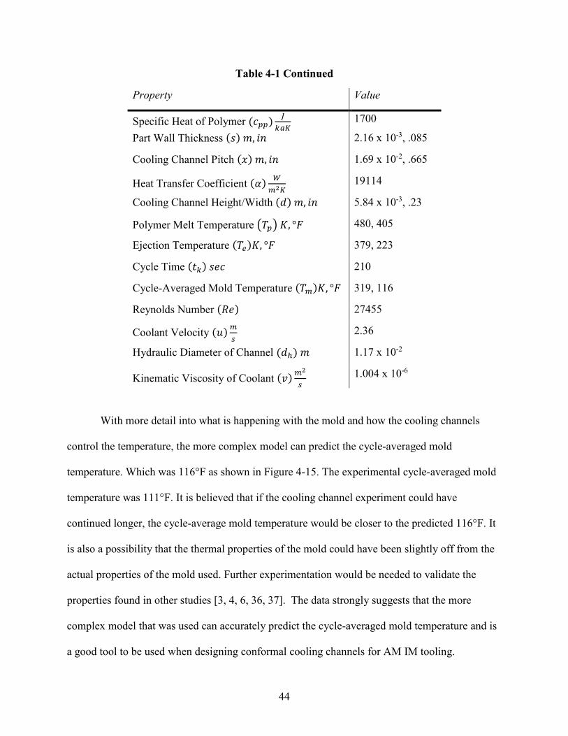
44
Table 4-1 Continued
Property
Value
Specific Heat of Polymer (𝑐𝑐𝑝𝑝𝑝𝑝) 𝐽𝐽𝑘𝑘𝑘𝑘𝑚𝑚
1700
Part Wall Thickness (𝑠𝑠) 𝑚𝑚, 𝑖𝑖𝑖𝑖 2.16 x 10⁻³, .085
Cooling Channel Pitch (𝑥𝑥) 𝑚𝑚, 𝑖𝑖𝑖𝑖 1.69 x 10⁻², .665
Heat Transfer Coefficient (𝛼𝛼) 𝑊𝑊𝑚𝑚2𝑚𝑚
19114
Cooling Channel Height/Width (𝑑𝑑) 𝑚𝑚, 𝑖𝑖𝑖𝑖 5.84 x 10⁻³, .23
Polymer Melt Temperature �𝑇𝑇𝑝𝑝� 𝐾𝐾, °𝐹𝐹 480, 405
Ejection Temperature (𝑇𝑇𝑒𝑒)𝐾𝐾, °𝐹𝐹 379, 223
Cycle Time (𝑡𝑡𝑘𝑘) 𝑠𝑠𝑅𝑅𝑐𝑐 210
Cycle-Averaged Mold Temperature (𝑇𝑇𝑚𝑚)𝐾𝐾, °𝐹𝐹 319, 116
Reynolds Number (𝑅𝑅𝑅𝑅) 27455
Coolant Velocity (𝑢𝑢)𝑚𝑚𝑠𝑠
2.36
Hydraulic Diameter of Channel (𝑑𝑑ℎ) 𝑚𝑚 1.17 x 10⁻²
Kinematic Viscosity of Coolant (𝑣𝑣)𝑚𝑚2
𝑠𝑠 1.004 x 10⁻⁶
With more detail into what is happening with the mold and how the cooling channels
control the temperature, the more complex model can predict the cycle-averaged mold
temperature. Which was 116°F as shown in Figure 4-15. The experimental cycle-averaged mold
temperature was 111°F. It is believed that if the cooling channel experiment could have
continued longer, the cycle-average mold temperature would be closer to the predicted 116°F. It
is also a possibility that the thermal properties of the mold could have been slightly off from the
actual properties of the mold used. Further experimentation would be needed to validate the
properties found in other studies [3, 4, 6, 36, 37]. The data strongly suggests that the more
complex model that was used can accurately predict the cycle-averaged mold temperature and is
a good tool to be used when designing conformal cooling channels for AM IM tooling.

45
5 CONCLUSIONS
Digital ABS and High Temp Resin AM IM tooling were produced using polymer jetting and
SLA processes, respectively. They were tested until failure which resulted in producing 66 shots
for Digital ABS and 3 shots for High Temp Resin. The mold design was then modified to include
conformal cooling channels and was produced in Digital ABS using polymer jetting. The
temperature of the mold was logged during the injection molding process and compared to the
temperature of the benchmark mold. On average, the temperature of the mold with cooling
channels was 44°F cooler than the mold without. The mold with conformal cooling channels had
a cycle-averaged mold temperature of 111°F. Studies show that AM IM tooling life is
significantly improved when the cycle-averaged temperature remains below 120°F [5, 6, 13].
Furthermore, the experimental data was compared to a conformal cooling channel model to see
how well the model could predict the cycle-averaged mold temperature. The model predicted a
cycle-averaged mold temperature of 116°F.
The results of this study strongly suggest that the addition of conformal cooling channels
to AM IM tooling will reduce the cycle-averaged mold temperature to a level that research has
shown to improve tooling life significantly. This study also validated the cooling channel model
and its use for the Digital ABS material. Because the cooling channel test was only performed
with one half of the inserts cooled, one could only expect better results as far as cooling time and
overall cycle time. Using the cooling channels in the AM IM tooling will help lengthen the life

46
of the tool and help reduce the cycle time of part production. This solution has the potential to
expand the use case for AM IM tooling by allowing for a higher volume of parts produced
whether it be for production parts, for prototyping and testing, or for mold design validation.
The major focus of this study was the effect that the conformal cooling channels had on
the cycle-averaged mold temperature. More research could be done with conformal cooling
channels to see how it effects the life of the tooling over a complete tool life cycle. Other, more
cost effective, materials should be studied as well, and the addition of conformal cooling
channels may expand the number of materials able to be used for IM tooling.

47
REFERENCES
[1] Salonitis, K. "Stereolithography.” Comprehensive Materials Processing 10 (2014): 19-67. [2] Stampfl, J., S. Baudis, C. Heller, R. Liska, A. Neumeister, R. Kling, A. Ostendorf, and M. Spitzbart. "Photopolymers with tunable mechanical properties processed by laser-based high-resolution stereolithography." Journal of Micromechanics and Microengineering 18, no. 12 (2008): 125014. [3] Mendible, G. A., J. A. Rulander, and S. P. Johnston. "Comparative study of rapid and conventional tooling for plastics injection molding." Rapid Prototyping Journal (2017). [4] Volpato, N., D. M. Solis, and C. A. Costa. "An analysis of Digital ABS as a rapid tooling material for polymer injection moulding." International Journal of Materials and Product Technology 52, no. 1-2 (2016): 3-16. [5] Rahmati, S., and P. Dickens. "Rapid tooling analysis of Stereolithography injection mould tooling." International Journal of Machine Tools and Manufacture 47, no. 5 (2007): 740-747. [6] Davoudinejad, A., M. Bayat, D. B. Pedersen, Y. Zhang, J. H. Hattel, and G. Tosello. "Experimental investigation and thermo-mechanical modelling for tool life evaluation of photopolymer additively manufactured mould inserts in different injection moulding conditions." The International Journal of Advanced Manufacturing Technology 102, no. 1-4 (2019): 403-420. [7] Schuh, G., G. Bergweiler, G. Lukas, and M. Oly. "Towards Temperature Control Measures for Polymer Additive Injection Molds." Procedia CIRP 93 (2020): 90-95. [8] Diegel, O. "Additive Manufacturing: An Overview." Comprehensive Materials Processing 10 (2014): 3-18. [9] Chua, C. K, K. F. Leong, and Z. H. Liu. "Rapid tooling in manufacturing." Handbook of Manufacturing Engineering and Technology (2013): 1-22. [10] Ong, H. S., C. K. Chua, and C. M. Cheah. "Rapid moulding using epoxy tooling resin." The International Journal of Advanced Manufacturing Technology 20, no. 5 (2002): 368-374. [11] Tosello, G., A. Charalambis, L. Kerbache, M. Mischkot, D. B. Pedersen, M. Calaon, and H. N. Hansen. "Value chain and production cost optimization by integrating additive manufacturing

48
in injection molding process chain." The International Journal of Advanced Manufacturing Technology 100, no. 1-4 (2019): 783-795. [12] Sachs, E., E. Wylonis, S. Allen, M. Cima, and H. Guo. "Production of injection molding tooling with conformal cooling channels using the three dimensional printing process." Polymer Engineering & Science 40, no. 5 (2000): 1232-1247. [13] “PolyJet for Injection Molding Technical Application Guide.” Stratasys. Accessed September 26, 2020. https://www.stratasys.com/resources/search/resource-guides/polyjet-injection-molding. [14] “Injection Molding from 3D Printed Molds: A Study of Low-Volume Production of Small Plastic Parts.” Formlabs, June 2020. https://3d.formlabs.com/injection-molding/. [15] “Standard Materials for High-Resolution Rapid Prototyping.” n.d. Accessed October 8, 2020. https://formlabs-media.formlabs.com/datasheets/Clear_Resin_Technical.pdf. [16] “High Temp High Temp Resin for Heat Resistance.” 2016. https://formlabs-media.formlabs.com/datasheets/High_Temp_Technical.pdf. [17] “Digital ABS Plus: A Heat Resistant 3D Printing Material.” n.d. Stratasys. Accessed October 8, 2020. https://www.stratasys.com/materials/search/digital-abs-plus. [18] Nelson, J. W., J. J. LaValle, B. D. Kautzman, J. K. Dworshak, E. M. Johnson, and C. A. Ulven. "Injection Molding with an Additive Manufacturing Tool: Study shows that 3D printed tools can create parts comparable to those made with P20 tools, at a much lower cost and lead time." Plastics Engineering 73, no. 7 (2017): 60-66. [19] Storsanden, A. L., M. Våle, and R. M. C. Ratnayake. "Use of additive manufacturing for polymer tooling: Case study from reaction injection molding." In 2017 IEEE International Conference on Industrial Engineering and Engineering Management (IEEM), (2017): 1607-1610. [20] Mischkot, M., A. Davoudinejad, A. Charalambis, T. Hofstätter, G. Tosello, D. B. Pedersen, and H. Nørgaard. "Dimensional accuracy of Acrylonitrile Butadiene Styrene injection molded parts produced in a pilot production with an additively manufactured insert." In 33rd Conference of the Polymer Processing Society, at Cancun, Mexico. 2017. [21] Zhang, Y., D. B. Pedersen, A. S. Gøtje, M. Mischkot, and G. Tosello. "A Soft Tooling process chain employing Additive Manufacturing for injection molding of a 3D component with micro pillars." Journal of Manufacturing Processes 27 (2017): 138-144. [22] Simpson, P., A. D. Zakula, J. Nelson, J. K. Dworshak, E. M. Johnson, and C. A. Ulven. "Injection molding with an additive manufactured tool." Polymer Engineering & Science 59, no. 9 (2019): 1911-1918.

49
[23] Etesami, F., C. Mullens, R. Sahli, and T. Webb. "Improving the Performance of 3D Printed Molds for Plastic Injection Molding." Proceedings of 34th International Conference on Computers and Their Applications, vol 58 (2019): 438-443. [24] Ferreira, J. C., and A. Mateus. "Studies of rapid soft tooling with conformal cooling channels for plastic injection moulding." Journal of Materials Processing Technology 142, no. 2 (2003): 508-516. [25] Shinde, M. S., and K. M. Ashtankar. "Additive manufacturing–assisted conformal cooling channels in mold manufacturing processes." Advances in Mechanical Engineering 9, no. 5 (2017): 1687814017699764. [26] Tang, Y., Z. Gao, and Y. F. Zhao. "Design of conformal porous structures for the cooling system of an injection mold fabricated by Additive Manufacturing Process." Journal of Mechanical Design 141, no. 10 (2019). [27] Au, K. M., and K. M. Yu. "A scaffolding architecture for conformal cooling design in rapid plastic injection moulding." The International Journal of Advanced Manufacturing Technology 34, no. 5-6 (2007): 496-515. [28] Janczyk, M., R. McLaughlin, and P. McCarthy. "Rapid stereolithography tooling for injection molding: the effect of cooling channel geometry." Journal of Injection Molding Technology (USA) 1, no. 1 (1997): 72-78. [29] Wylonis, E. M. "Production of injection molding tooling with conformal cooling channels using the three dimensional printing process." PhD diss., Massachusetts Institute of Technology, 1995. [30] Kanbur, B. B., S. Suping, and F. Duan. "Design and optimization of conformal cooling channels for injection molding: a review." The International Journal of Advanced Manufacturing Technology 106, no. 7-8 (2020): 3253-3271. [31] Xu, X., E. Sachs, and S. Allen. "The design of conformal cooling channels in injection molding tooling." Polymer Engineering & Science 41, no. 7 (2001): 1265-1279. [32] Rao, N. S., G. Schumacher, N. R. Schott, and K. T. O’brien. "Optimization of Cooling Systems in Injection Molds by an Easily Applicable Analytical Model." Journal of Reinforced Plastics and Composites 21, no. 5 (2002): 451-459. [33] Strong, A. B. Plastics: Materials and Processing. Upper Saddle River, NJ: Pearson Prentice Hall, 2006. [34] Kazmer, D. Injection Mold Design Engineering. Munich, 2016. [35] Wang, Y., K. Yu, and C. C.L. Wang. "Spiral and conformal cooling in plastic injection molding." Computer-Aided Design 63 (2015): 1-11.

50
[36] “Reynolds Number.” Engineering ToolBox. Accessed October 8, 2020. https://www.engineeringtoolbox.com/reynolds-number-d_237.html. [37] “Thermoplastics - Physical Properties.” Engineering ToolBox. Accessed October 8, 2020. https://www.engineeringtoolbox.com/physical-properties-thermoplastics-d_808.html.