
Effective Means of Silt Fence Installation Means of Silt Fence Installation Abstract Surface water...
34
Effective Means of Silt Fence Installation Prepared By: Kody R. Featherston Candice L. Johnson J. Kent Evatt Monica L. Johnston Biosystems and Agricultural Engineering Department Oklahoma State University Submitted To: ASAE AGCO Design Competition Committee May 20 th , 2004
-
Upload
phungxuyen -
Category
Documents
-
view
227 -
download
0
Transcript of Effective Means of Silt Fence Installation Means of Silt Fence Installation Abstract Surface water...

Effective Means of Silt Fence Installation
Prepared By:
Kody R. Featherston
Candice L. Johnson
J. Kent Evatt
Monica L. Johnston
Biosystems and Agricultural Engineering Department
Oklahoma State University
Submitted To:
ASAE AGCO Design Competition Committee
May 20th, 2004

Effective Means of Silt Fence Installation
Kody R. Featherston
Candice L. Johnson
J. Kent Evatt
Monica L. Johnston
Biosystems and Agricultural Engineering Department
Oklahoma State University
Advisor: Dr. Paul R. Weckler
Submission Date: May 20th, 2004
Kody R. Featherston Biomechanical Option May 2004 Graduate Great Falls, Montana
Candice L. Johnson Biomechanical Option December 2004 Graduate Ankeny, Iowa
J. Kent Evatt Biomechanical Option May 2004 Graduate Ralston, Oklahoma
Monica L. Johnston Environmental Option May 2004 Graduate Stillwater, Oklahoma
Dr. Ronald L. Elliott BAE Department Head
Dr. Paul R. Weckler Senior Design Advisor
ii

Effective Means of Silt Fence Installation
Abstract
Surface water pollution can be greatly reduced through the installation of effective silt fence. Silt fence is placed around construction sites in which the top soil is exposed. Silt fence is typically ineffective due to poor design and installation. The objective of this project was to design and build a machine capable of installing silt fence properly. Enviro-Mech is a design team formed by four senior students in the Biosystems and Agricultural Engineering Department at Oklahoma State University. Enviro-Mech is to create a machine which installs silt fence to standards established by the Failure Avoidance and Effective Silt Fence Technology (FAESF) group using a vibratory plow manufactured by Charles Machine Works, Inc. Results of this project reflect the extent to which Enviro-Mech has accomplished the design criteria. The FAESF group required that the new equipment be compatible with their new fence design and that it does not promote installation-related erosion. More specifically, the design criteria provided by the FAESF group require that the new installation equipment be capable of installing fence in a trench eight to ten inches deep, with soil backfilled and compacted. Charles Machine Works, Inc. also provided design criteria which required that the final design be compatible with current Ditch Witch vibratory plows and that the final prototype be economically feasible and marketable. Through the production of a prototype and extensive testing, these criteria have been measured. Results meet or exceed the sponsors’ requirements.
Acknowledgements • Kelvin Self – Manager of Research and Development at Charles Machine Works • Richard Sharp – Project Engineer at Charles Machine Works • Dr. Billy Barfield – Oklahoma State University Failure Avoidance and Effective Silt
Fence Technology Research Group • Dr. Ellen Stevens – Oklahoma State University Failure Avoidance and Effective Silt
Fence Technology Research Group • Wayne Kiner – Oklahoma State University Biosystems and Agricultural Engineering
Laboratory Manager • Dr. Paul Weckler – Oklahoma State University Biosystems and Agricultural
Engineering Senior Design Advisor
iii
Table of Contents Abstract............................................................................................................................. iii
Acknowledgements .......................................................................................................... iii
Figures............................................................................................................................... vi
Tables ............................................................................................................................... vii
Introduction....................................................................................................................... 1
Problem Definition............................................................................................................ 1
Statement of Work............................................................................................................ 3
Investigation ...................................................................................................................... 4
Currently Recommended Silt Fence Practices................................................... 4
Current Equipment Patented and in Production .............................................. 4
Similar Vibratory Plow Applications.................................................................. 6
Design Criteria .................................................................................................................. 7
Concept Development....................................................................................................... 9
Potential Solutions ............................................................................................................ 9
Proposal A – Two-Disk Method........................................................................... 9
Proposal B – Feed Channel Method.................................................................... 9
Proposal C – Tension Rod Method.................................................................... 10
Testing and Analysis ....................................................................................................... 10
Methods Testing.................................................................................................. 10
Concept Testing................................................................................................... 11
Final Design Testing ........................................................................................... 15
Final Design ..................................................................................................................... 17
Frame ................................................................................................................... 17
Components ......................................................................................................... 19
Operator’s Manual ......................................................................................................... 21
Project Schedule.............................................................................................................. 22
Cost Analysis ................................................................................................................... 22
Prototype Budget ................................................................................................ 22
Prototype Fabrication Cost................................................................................ 22
Estimated Manufacturing Cost ......................................................................... 23
Competitive Comparison.................................................................................... 23
iv

Conclusion ....................................................................................................................... 24
References........................................................................................................................ 26
Appendices....................................................................................................................... 27
v

Figures1. Properly Installed Silt Fence........................................................................................ 1
2. Failure due to Concentrated Parallel Flow ................................................................ 1
3. Failure resulting from Excessive Stretching and Overtopping ................................ 2
4. New Fence Configuration from the FAESF ............................................................... 3
5. Current NRCS Recommended Practices.................................................................... 4
6. Tommy Silt Fence Machine.......................................................................................... 5
7. McCormick Silt Fence and Waterway Fabric Installation Plow.............................. 5
8. ImpleMax SF12c Silt Fence Installer .......................................................................... 6
9. Four-Bar Linkage for Cable Applications.................................................................. 7
10. Cable Installation Blade ............................................................................................. 7
11. Design Specifications from the FAESF Research Group........................................ 7
12. Ditch Witch SK500 with Vibratory Plow Attachment ............................................ 8
13. Two-Disk Method Diagram ....................................................................................... 9
14. Feed Channel Method................................................................................................. 9
15. Tension Rod Method................................................................................................. 10
16. SK500 Creating Slot ................................................................................................. 11
17. Silt Fence Hand-Inserted into Slot .......................................................................... 11
18. Tension Rod in Slot................................................................................................... 11
19. Vibratory Plow with Extensions and Square Testing Frame ............................... 12
20. Experimental Shield and Load Cell ....................................................................... 12
21. Load Data for Three Passes ..................................................................................... 13
22. Shield Pulling Out of Ground during Testing........................................................ 13
23. Shield with Toe Added.............................................................................................. 13
24. Over-the-Top Frame Concept ................................................................................. 14
25. Wrap-Around Frame Concept ................................................................................ 14
26. Testing New Pivot Design and Tension Rod Mounting......................................... 14
27. Adjustable Frame to Find Proper Fabric Roll Location and Orientation .......... 15
28. Packing Wheel........................................................................................................... 15
29. Fabric Unrolling due to Wind.................................................................................. 16
30. Curved Installation Path .......................................................................................... 16
31. Spring Scale Testing to Determine the Force Required to remove Fabric from the Soil.............................................................................................................. 17
vi

32. Rainfall Simulation at NRCS-ARS Hydraulics Lab.............................................. 17
33. Main Frame on SK500.............................................................................................. 18
34. Exploded View of Main Pivot .................................................................................. 18
35. Sub-Frame Mounted to Main Frame and SK500 .................................................. 19
36. Revised Shield ........................................................................................................... 19
37. Tension Rod............................................................................................................... 20
38. Fabric Tension Arm.................................................................................................. 20
39. Depth Selector Positions ........................................................................................... 21
40. Packing Wheels ......................................................................................................... 21
41. Tension Rod Pivot Point........................................................................................... 21
42. Installed Fence........................................................................................................... 24
43. Final Prototype with Design Team.......................................................................... 25
Tables 1. Sping Test Results ....................................................................................................... 16
2. Silt Fence Installer Proposed Budget ........................................................................ 22
3. OSU Silt Fence Installer Prototype Fabrication Cost ............................................. 23
4. Estimated Manufacturing Cost for OSU Silt Fence Installer................................. 23
5. Price Comparision with Products Currently Available .......................................... 24
vii

Introduction
Silt fence is a temporary sediment barrier consisting of filter fabric entrenched in the soil and attached to supporting posts (fig. 1) (Salix, 2000). A silt fence is solely intended to control sediment. Current designs consist of a vertical geotextile fabric with a toe section compacted into the soil and vertical stakes holding it in place. The geotextile is designed to retain sediment-laden water, allowing the soil particles to fall out of suspension and separate from the runoff. This restriction traps the eroded soils, preventing offsite pollution of surface waters surrounding construction sites.
Figure 1. Properly Installed Silt Fence (Salix, 2000)
Problem Definition
Current methods of installation are the primary causes of fence failure (Salix, 2000). Proper design of the fence requires that it be installed along the contour of the slope, preventing runoff from traveling along the length of the fence. If the fence is installed along the slope, it can create concentrated flow that may increase erosion (fig. 2). An edge or toe of the fabric is installed in a shallow trench that is rarely compacted adequately, thereby allowing undercutting to occur.
Placement of the fabric is also critical when determining the volume of water that can be retained behind the fence and the area of runoff being captured by each section of fence. If the area of runoff is too great, the fence will stretch and eventually be overtopped allowing soil particulates to leave the site (fig. 3). In addition, supporting posts are typically undersized and unable to support the forces imposed during times of high runoff flow.
Figure 2. Failure due to Concentrated Parallel Flow (Barfield et al., 2000)
1
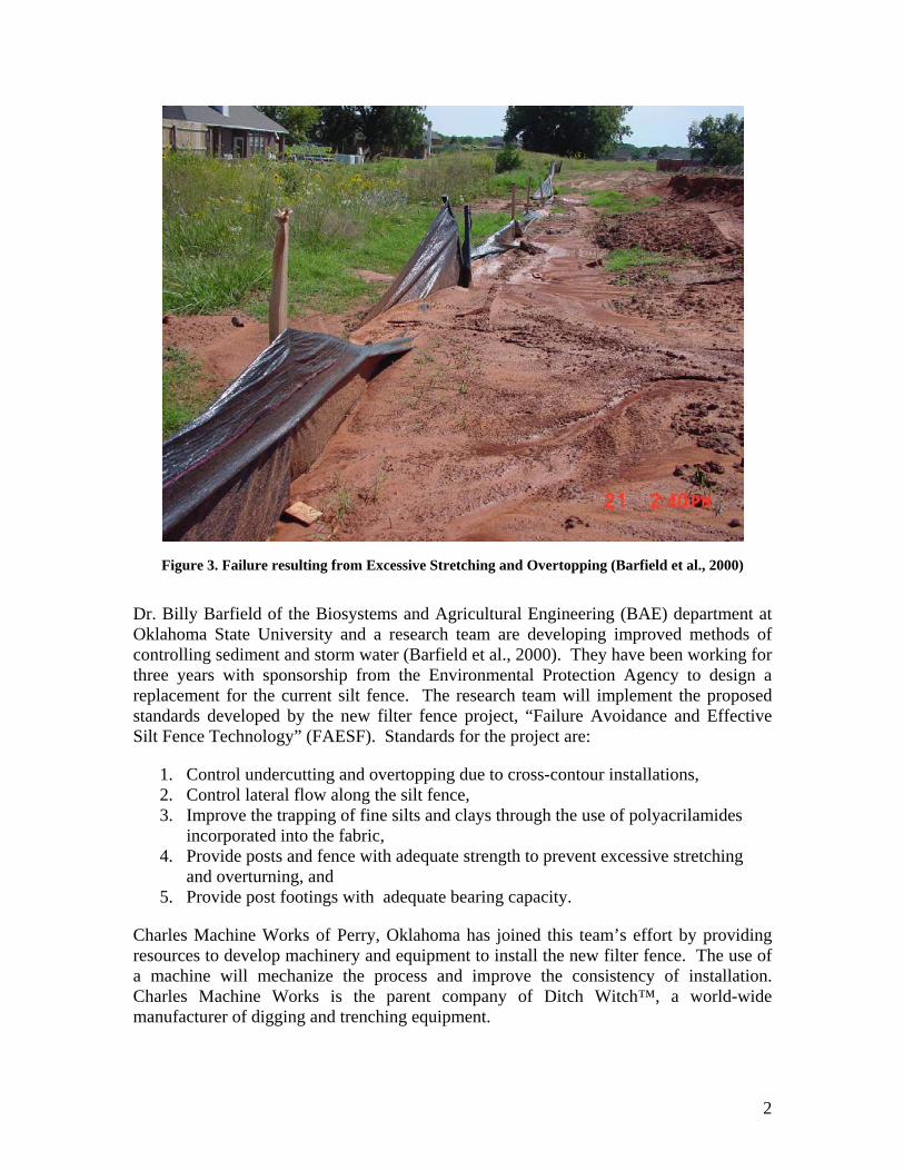
Figure 3. Failure resulting from Excessive Stretching and Overtopping (Barfield et al., 2000)
Dr. Billy Barfield of the Biosystems and Agricultural Engineering (BAE) department at Oklahoma State University and a research team are developing improved methods of controlling sediment and storm water (Barfield et al., 2000). They have been working for three years with sponsorship from the Environmental Protection Agency to design a replacement for the current silt fence. The research team will implement the proposed standards developed by the new filter fence project, “Failure Avoidance and Effective Silt Fence Technology” (FAESF). Standards for the project are:
1. Control undercutting and overtopping due to cross-contour installations, 2. Control lateral flow along the silt fence, 3. Improve the trapping of fine silts and clays through the use of polyacrilamides
incorporated into the fabric, 4. Provide posts and fence with adequate strength to prevent excessive stretching
and overturning, and 5. Provide post footings with adequate bearing capacity.
Charles Machine Works of Perry, Oklahoma has joined this team’s effort by providing resources to develop machinery and equipment to install the new filter fence. The use of a machine will mechanize the process and improve the consistency of installation. Charles Machine Works is the parent company of Ditch Witch™, a world-wide manufacturer of digging and trenching equipment.
2

Statement of Work
The Enviro-Mech design group is composed of four BAE students in BAE 4012 Senior Design. Enviro-Mech’s efforts focused on reducing failures due to improper installation procedures while Dr. Barfield’s team continued to develop the new filter fence material configuration and the fence support mechanism. Because the filter fence design is still being finalized, the installation equipment will be designed to handle the current proposed standard for the fence design (fig. 4).
Figure 4. New Fence Configuration from the FAESF (Barfield et al., 2000)
A machine was designed, built, and tested to install the fence. It was capable of handling a large roll of the filter fence material. Filter fence material was placed in a trench and soil was re-compacted around the fabric. Final dimensions and shape of the trench was determined through testing. Filter fence material has a section that lies on the ground as an apron helping reduce the possibility of undercutting. This apron was stretched along the ground surface and then attached to vertical supports. Methods for handling the material and installing the fabric properly were investigated by the design team. Installation was divided into two steps. In phase two, a second machine will be developed to install vertical supports and attach the fabric. This portion of the project was not addressed by the Enviro-Mech design team.
3
Investigation
Currently Recommended Silt Fence Practices
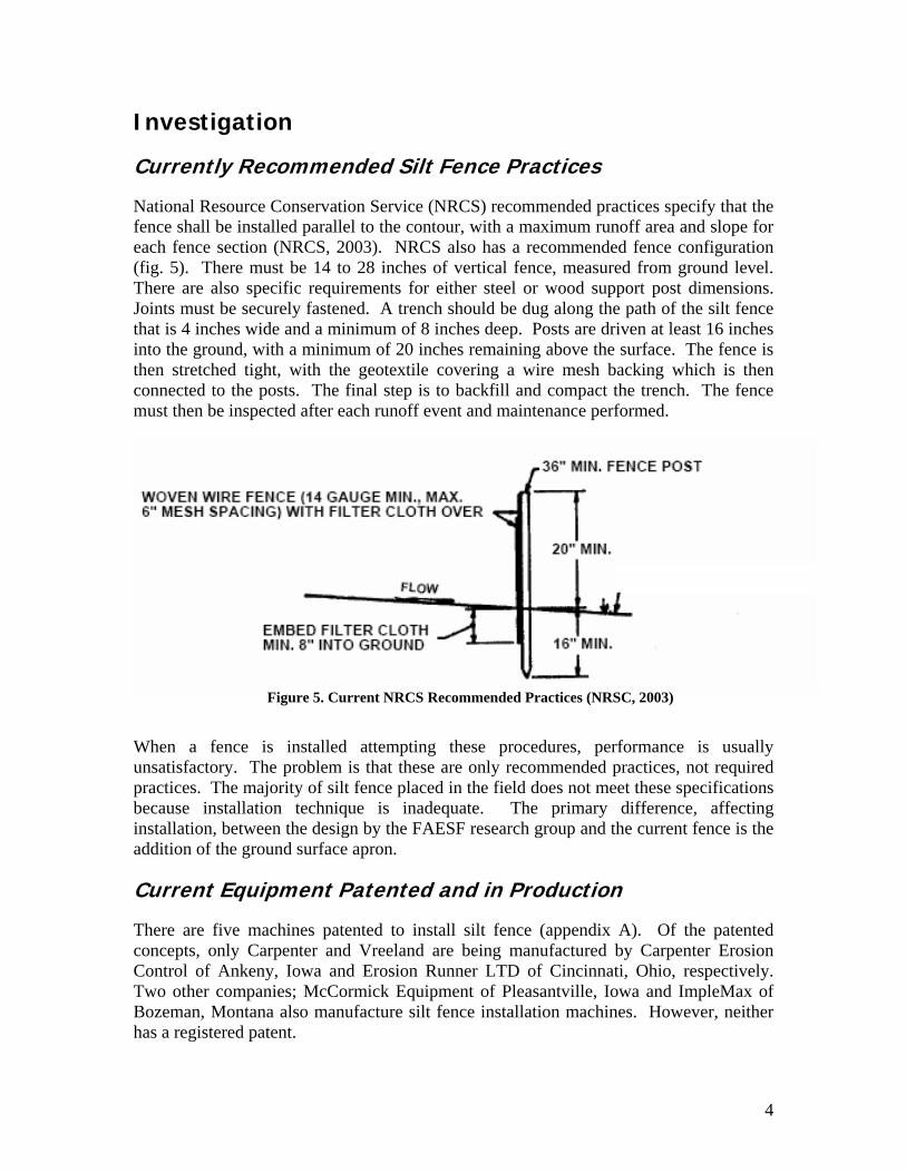
National Resource Conservation Service (NRCS) recommended practices specify that the fence shall be installed parallel to the contour, with a maximum runoff area and slope for each fence section (NRCS, 2003). NRCS also has a recommended fence configuration (fig. 5). There must be 14 to 28 inches of vertical fence, measured from ground level. There are also specific requirements for either steel or wood support post dimensions. Joints must be securely fastened. A trench should be dug along the path of the silt fence that is 4 inches wide and a minimum of 8 inches deep. Posts are driven at least 16 inches into the ground, with a minimum of 20 inches remaining above the surface. The fence is then stretched tight, with the geotextile covering a wire mesh backing which is then connected to the posts. The final step is to backfill and compact the trench. The fence must then be inspected after each runoff event and maintenance performed.
Figure 5. Current NRCS Recommended Practices (NRSC, 2003)
When a fence is installed attempting these procedures, performance is usually unsatisfactory. The problem is that these are only recommended practices, not required practices. The majority of silt fence placed in the field does not meet these specifications because installation technique is inadequate. The primary difference, affecting installation, between the design by the FAESF research group and the current fence is the addition of the ground surface apron.
Current Equipment Patented and in Production
There are five machines patented to install silt fence (appendix A). Of the patented concepts, only Carpenter and Vreeland are being manufactured by Carpenter Erosion Control of Ankeny, Iowa and Erosion Runner LTD of Cincinnati, Ohio, respectively. Two other companies; McCormick Equipment of Pleasantville, Iowa and ImpleMax of Bozeman, Montana also manufacture silt fence installation machines. However, neither has a registered patent.
4
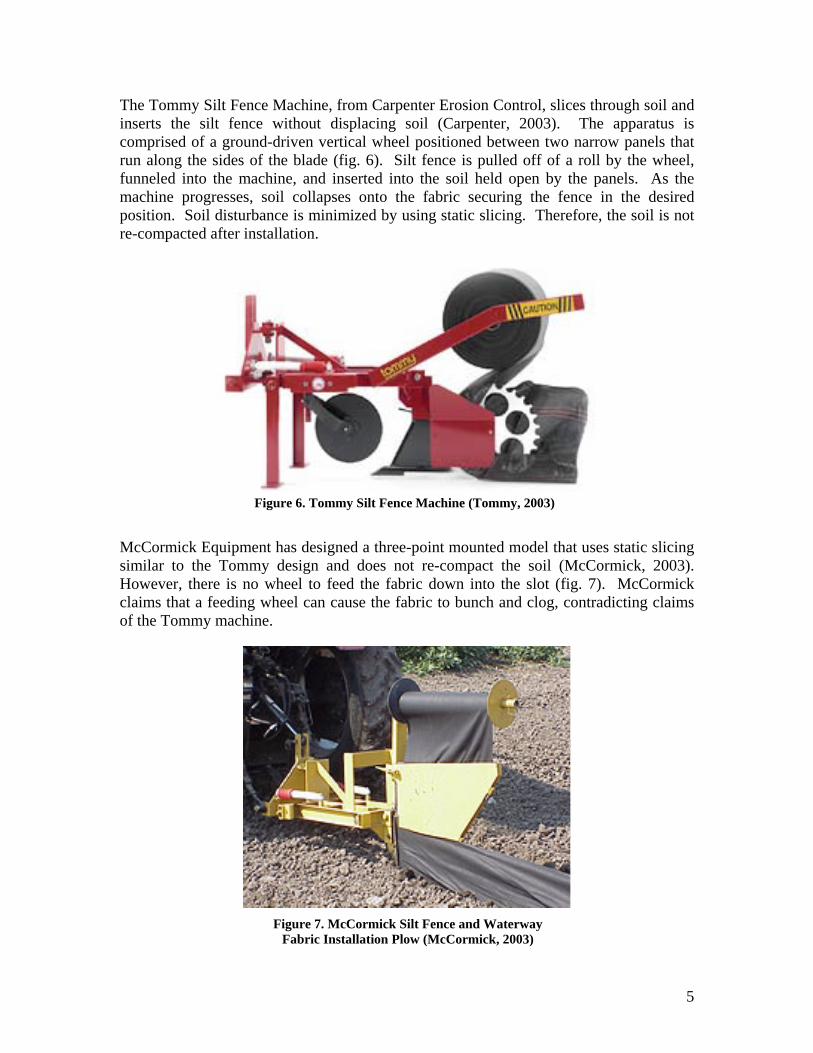
The Tommy Silt Fence Machine, from Carpenter Erosion Control, slices through soil and inserts the silt fence without displacing soil (Carpenter, 2003). The apparatus is comprised of a ground-driven vertical wheel positioned between two narrow panels that run along the sides of the blade (fig. 6). Silt fence is pulled off of a roll by the wheel, funneled into the machine, and inserted into the soil held open by the panels. As the machine progresses, soil collapses onto the fabric securing the fence in the desired position. Soil disturbance is minimized by using static slicing. Therefore, the soil is not re-compacted after installation.
McCormick Equipment has designed a three-point mounted model that uses static slicing similar to the Tommy design and does not re-compact the soil (McCormick, 2003). However, there is no wheel to feed the fabric down into the slot (fig. 7). McCormick claims that a feeding wheel can cause the fabric to bunch and clog, contradicting claims of the Tommy machine.
Figure 7. McCormick Silt Fence and Waterway Fabric Installation Plow (McCormick, 2003)
Figure 6. Tommy Silt Fence Machine (Tommy, 2003)
5

The Erosion Runner design incorporates a plow blade with curved surfaces on both the front and rear edges creating a trapezoid-like shape (Erosion Runner, 2003). A guide follows directly behind the plow blade and feeds fabric into the slot created. After installation, the ground is compacted by the tractor wheel while posts are driven into the ground using a hydraulically actuated impact cylinder.
The ImpleMax SF12c Silt Fence Installer uses a vibratory plow to create a slit and is designed to attach to front-end loaders and skid steers with standard quick connections (fig. 8) (ImpleMax, 2003). The fence has a shaped edge that passes through a formed channel on the back edge of the plow blade. This feature ensures that the fence is fed to the base of the slit. Patents are pending on this technology.
Similar Vibratory Plow Applications
Charles Machine Works currently produces vibratory plows to install communication cables (Ditch Witch, 2001). A vibratory plow utilizes engine power to vibrate the blade up and down. This motion decreases the total power required to pull the blade through the soil. There are two designs for this application. The first has a separate channel to feed cable attached to the back of the blade through a four-bar linkage (fig. 9). This design allows the cable to float in the bottom of the slot without moving up-and-down with the plow.
The second design is comprised of two flanges located at the back edge of the blade creating a groove to feed the cable (fig. 10). A guide plate extends along the length of the groove and lies into the groove to hold the cable in place.
Figure 8. ImpleMax SF12c Silt Fence Installer (ImpleMax, 2003)
6

toe of the fence be secured in a fashion that will prevent
Figure 11. Design Specifications from the FAESF Research Group
Design Criteria
The new machine for installing the filter fence must be compatible with the overall purpose of filter fence. It must not promote concentrated flows that increase the risk of soil erosion. Approximate dimensions of the final fence design have been provided by the FAESF research group (fig. 11). The overall filter fence design consists of a secured toe, an apron, and the vertical fence portion supported by posts. The FAESF standards require that the
Figure 10. Cable Installation Blade
Guide Plate Groove
Figure 9. Four-Bar Linkage for Cable Applications
7

undercutting and allow the water to move up onto the apron portion, unobstructed. In order to ensure that the water flow does not divert along the toe, the installation must protect the toe with compacted soil and avoid creating depressions that could act as channels. Once the runoff reaches the apron portion, the filter fence can begin the process of impounding the runoff and allowing sediment to settle without erosion or undercutting.
Charles Machine Works has requested that the design be compatible with a current production vibratory plow. The final design should be economically feasible, and the design should be marketable. Depending on the required power, the SK500, 255SX, and the 410SS vibratory plows have been recommended (fig. 12). Operator safety was also taken into consideration when making design decisions.
The SK500 is unique due to a design that allows for quick-change attachments. The filter fence installation machine could potentially be an attachment for this product. The latter two models are dedicated machines with specific, fixed attachments. This limitation would increase the overall price of a silt fence installation machines, because they could not be used for other applications when not installing silt fence. The final design objectives are:
1. Capable of handling current and new filter fabric rolls, 2. Compatible with a current vibratory plow model, 3. Installs to the depth required to secure the fabric, 4. Compacts soil after installation to prevent undercutting, and 5. Operates in many soil types and conditions.
Figure 12. Ditch Witch SK500 with Vibratory Plow Attachment
8

Concept Development
Enviro-Mech team members compiled ideas independently. The group then met to evaluate the designs. Modifications were made to each of the designs. Action items were assigned to members at the end of each of these meetings in order to continue the investigation and progress of the project. Methods of installation, trench dimensions,
Potential Solutions
Proposal A – Two-Disk Method
The first design concept utilized two narrow disks to feed the fabric into a slot (fig. 13). The roll of fabric was oriented vertically, and the fabric was fed into the disks that follow the plow and rotate at the speed of travel. The disks pinch the fabric above ground and ensure that it is pulled down into the base of the slot where the fabric is released. This apparatus is followed by packing wheels to ensure the soil is re-compacted into the slot to resist. This concept is similar to the operation of a row crop planter.
Proposal B – Feed Channel Method
application, the end of the fabric could have a cord or a T-shaped edge. During installation, the fence edge
l and placed at the bottom e plow. The fence was guided
s wheels following behind the
web handling techniques, and re-compaction designs were all developed separately. By developing concepts individually, the ideas for each component can create many different combinations in an effort to develop the most effective machine. After comparing the various designs, the overall best methods were selected by the team to begin the first stages of testing.
Figure 13. Two-Disk Method Diagram
Fig
A channel was attached to the rear of the vibratory plow blade similar to the current cable feeding (fig. 14). The fence required added bulk along one edge to secure it in the slot and allow it to be fed. For
was slid through the channeof the slot made by thinto the slot by presure 14. Feed Channel Method process.
9

Proposal C – Tension Rod Method
Testing was performed to determine the most effective and financially feasible method of i s: methods, concept, and final design. Testing occurred as part of the concept refinement phases. Initial testing determined if
oincorporated into a complete machdetermine overall complexity and to select the final design that achfence.
Methods Testing
le tointo slots created using a vibratory plow (fig. 16 and fig. 17). The slot was much narrower and collapsed more easily than expected.
A spring loaded rod was used to direct the fence material into the slot (fig. 15). The roll of fabric was parallel with the ground and perpendicular to the direction of travel. Fabric would fold around the rod when it made contact. The rod slid along the bottom of the slot, pinching the fabric at the bottom. The rod acted as a pressure point at the bottom of the slot, pulling more fabric around the rod and down into the slot as the machine traveled forward. The rod moved over the small flap of fabric at the bottom of the slot, leaving it stationed in the slot as the machine moves forward. A packing wheel followed, securing the fence in place.
Figure 15. Tension Rod Method
Testing and Analysis
nstallation. The testing was divided into three area
n were effective. Methods deemed adequate were ine design. Those machine designs were analyzed to manufacturing costs. This information was then used ieves all of the objectives for properly installing silt
allow quick execution. Fence was manually inserted
the various methods of installati
Methods testing was kept simp
10
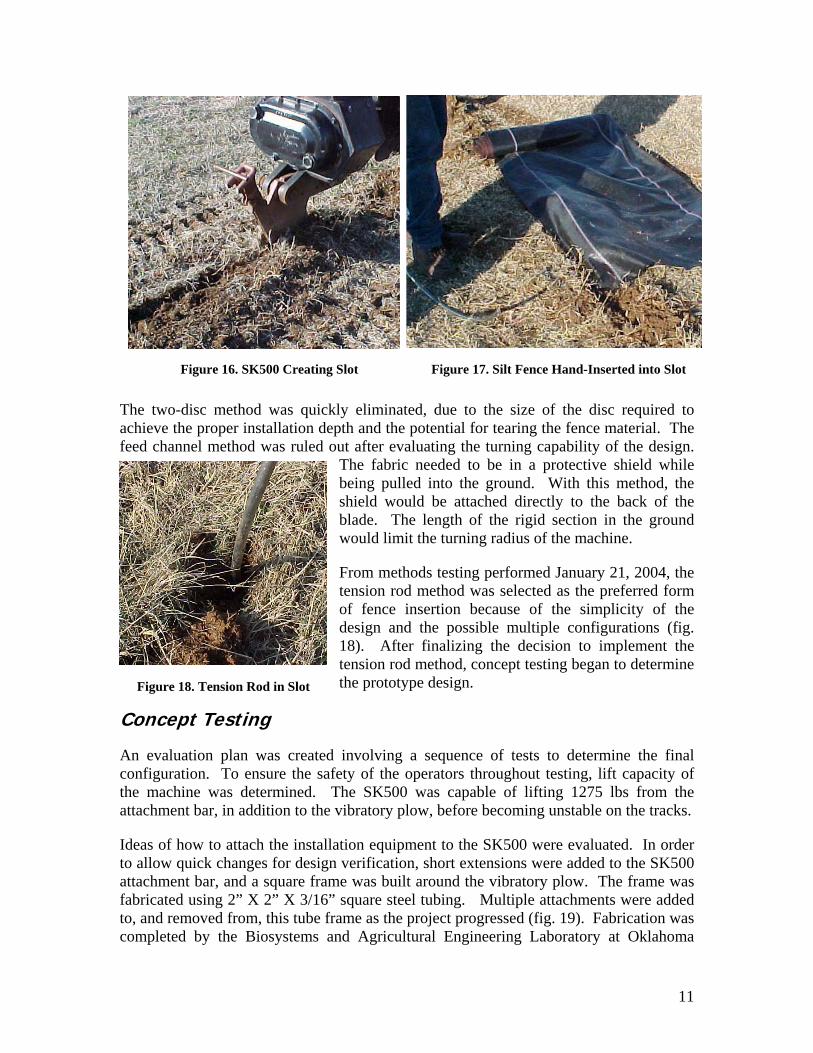
The two-disc method was quickly eliminated, due to the size of the disc required to achieve the proper installation depth and the potential for tearing the fence material. The feed channel method was ruled out after evaluating the turning capability of the design.
The fabric needed to be in a protective shield while being pulled into the ground. With this method, the shield would be attached directly to the back of the blade. The length of the rigid section in the ground
the machine.
From methods testing performed January 21, 2004, the nsion rod method was selected as the preferred form fence insertion because of the simplicity of the
configuration. To ensure the safety of the operators throughout testing, lift capacity of t ined. The SK500 was capable of lifting 1275 lbs from the attachment bar, in addition to the vibratory plow, before becoming unstable on the tracks.
ratory plow. The frame was fabricated using 2” X 2” X 3/16” square steel tubing. Multiple attachments were added to, and removed from, this tube frame as the project progressed (fig. 19). Fabrication was completed by the Biosystems and Agricultural Engineering Laboratory at Oklahoma
would limit the turning radius of
teofdesign and the possible multiple configurations (fig. 18). After finalizing the decision to implement the tension rod method, concept testing began to determine the prototype design.
Concept Testing
An evaluation plan was created involving a sequence of tests to determine the final
Figure 16. SK500 Creating Slot Figure 17. Silt Fence Hand-Inserted into Slot
Figure 18. Tension Rod in Slot
he machine was determ
Ideas of how to attach the installation equipment to the SK500 were evaluated. In order to allow quick changes for design verification, short extensions were added to the SK500 attachment bar, and a square frame was built around the vib
11

State University. The laboratory prefers to work with English units, therefore the remainder of this report is in English units.
ods testing, the group discovered that a shield would be needed to protect the e base of the slot. This shield will impose the primary
ndesigned and fabricated (fig. 20).to maintain strength, yet allow fleallow room for the rod and for fsteel plate, with a wide funnel-sha
During methfabric as it was inserted in thsource of frictional forces duri g fabric installation. An experimental shield was
A tension rod of 1/2-inch diameter steel was required xing. The shield was designed with a 3/4-inch gap to
abric feed. The shield was constructed from 1/8-inch ped mouth.
Figure 19. Vibratory Plow with Extensions and Square Testing Frame
Figure 20. Experimental Shield and Load Cell
12

Brackets for a load cell were built to enable measurement of the forces generated by entering the soil and being pulled through the ground. Forces collected during testing were read at the center of the shield (fig. 21). Each pass saw similar entry forces with a plateau at approximately 75 lbs. One pass exhibited higher forces, but this peak occurred when the shield deviated from the path created by the vibratory plow. The front edge of the shield broke its own path through the soil. The design group determined that the shield must follow the path of the blade, even when following contours.
ugh the soil were unchanged. Deflection in the load cell connections supporting the shield had caused the shield to lift out of the ground.
Figure 22. Shield Pulling
During the February 18, 2004 field test, the group observed that the back portion of the shield appeared to be coming out of the slot (fig. 22). A toe was added to the front of the shield in an effort to pull it down into the soil, reducing entry forces and preventing the back portion of the shield from lifting out of the soil (fig. 23). Adding a toe did not solve the problem. Forces entering and moving thro
Out of Ground during Testing Figure 23. Shield with Toe Added
0
25
50
75
100
125
0Time (sec)
Forc
e (lb
s)
5 10 15 20 25
Figure 21. Load Data for Three Passes
13

The initial concept for the frame consisted of two parallel frame rails connected to the extensions used with the square tube testing frame. Components following the vibratory blade were mounted between the two long rails. Two important concepts the group wanted to target were the ability of the shield to trail closely behind the blade and for the shield to pivot in order to follow the blade through a curved path. During load testing, the team observed that a very complex network of pivot points would be required in this parallel frame to follow the blade through the ground. This meant that the main frame must move with the vibratory plow and have a pivot point behind the plow for shield attachment, ruling out the use of extensions on the attachment bar.
Difficulty in designing a frame that could attach to components behind the vibratory blade, yet not interfere with the vibratory motor, forced the team to develop two new concepts (fig. 24 and fig. 25). The first frame, designed to use a bent plate that was boxed in to add rigidity, arched over the top of the vibratory plow. Due to increased bending moments created by the components mounted at the pivot point, this design was not pursued. Design concept two used rectangular tubing in an octagonal pattern to wrap around the vibratory plow.
A tension rod was fabricated with a radius of 18 inches similar to the rod used during methods testing. A pivot plate was attached at one end of the arc. Two support members were added to maintain the rigidity of the upper portion of the rod. The mounting bracket for the shield and tension rod was constructed from square tubing and attached to a pivot on the rear of the square testing frame (fig. 26). The shield was positioned between t o square tubes to maintain the inside gap.
Figure 24. Over-the-Top Frame Concept
Figure 26si
. Testing New Pivot De gn and Tensio tinn Rod Moun g
Figure 25. Wrap-Around Frame Concept
w
14
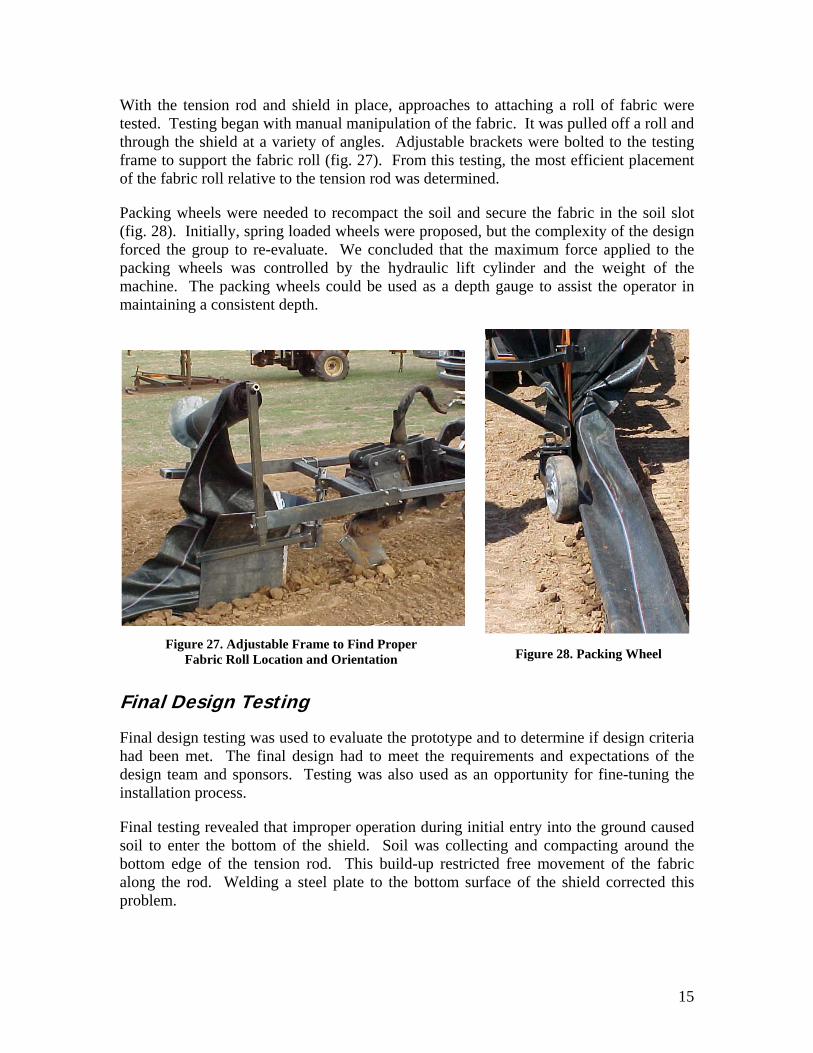
With the tension rod and shield in place, approaches to attaching a roll of fabric were tested. Testing began with manual manipulation of the fabric. It was pulled off a roll and through the shield at a variety of angles. Adjustable brackets were bolted to the testing frame to support the fabric roll (fig. 27). From this testing, the most efficient placement of the fabric roll relative to the tension rod was determined.
Packing wheels were needed to recompact the soil and secure the fabric in the soil slot (fig. 28). Initially, spring loaded wheels were proposed, but the complexity of the design forced the group to re-evaluate. We concluded that the maximum force applied to the packing wheels was controlled by the hydraulic lift cylinder and the weight of the
Final Design Testing
Final de rototyhad been met. The final design had to meet the requ
s an opportunity for fine-tuning the
initial entry into the ground caused llecting and compacting around the ricted free movement of the fabric
ield corrected this
Figure 28. Packing Wheel
machine. The packing wheels could be used as a depth gauge to assist the operator in maintaining a consistent depth.
Figure 27. Adjustable Frame to Find Proper
Fabric Roll Location and Orientation
sign testing was used to evaluate the p pe and to determine if design criteria irements and expectations of the
design team and sponsors. Testing was also used ainstallation process.
Final testing revealed that improper operation duringsoil to enter the bottom of the shield. Soil was cobottom edge of the tension rod. This build-up restalong the rod. Welding a steel plate to the bottom surface of the shproblem.
15
16
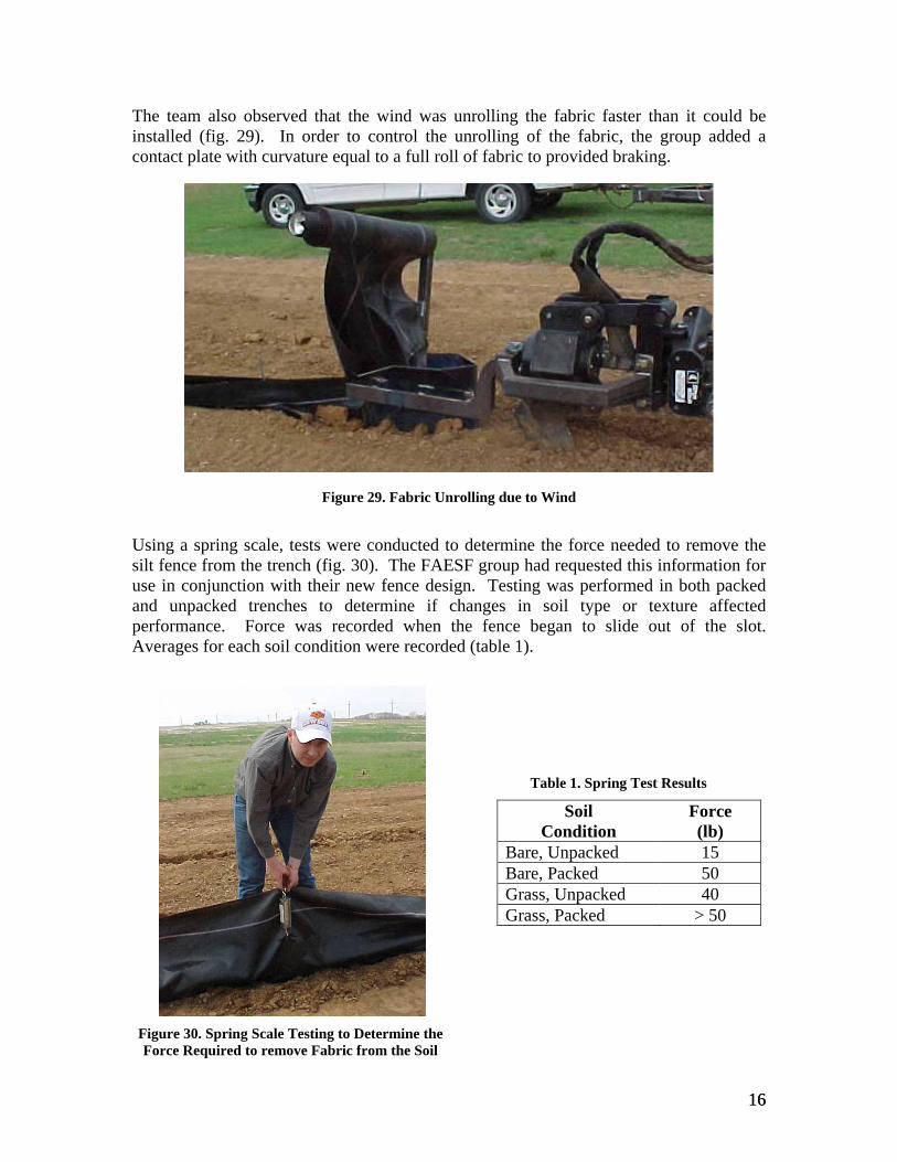
am also observed that the wind was unrolling the fabric faster than it could be installed (fig. 29). In order to control the unrolling of the fabric, the group added a contact plate with curvature equal to a full roll of fabric to provided braking.
Using a spring scale, tests were conducted to determine the force needed to remove the silt fence from the trench (fig. 30). The FAESF group had requested this information for use in conjunction with their new fence design. Testing was performed in both packed and unpacked trenches to determine if changes in soil type or texture affected performance. Force was recorded when the fence began to slide out of the slot. Averages for each soil condition were recorded (table 1).
Table 1. Spring Test Results
Soil Condition
Force (lb)
The te
Bare, Unpacked 15 Bare, Packed 50 Grass, Unpacked 40 Grass, Packed > 50
Figure 29. Fabric Unrolling due to Wind
Figure 30. Spring Scale Testing to Determine the Force Required to remove Fabric from the Soil
16
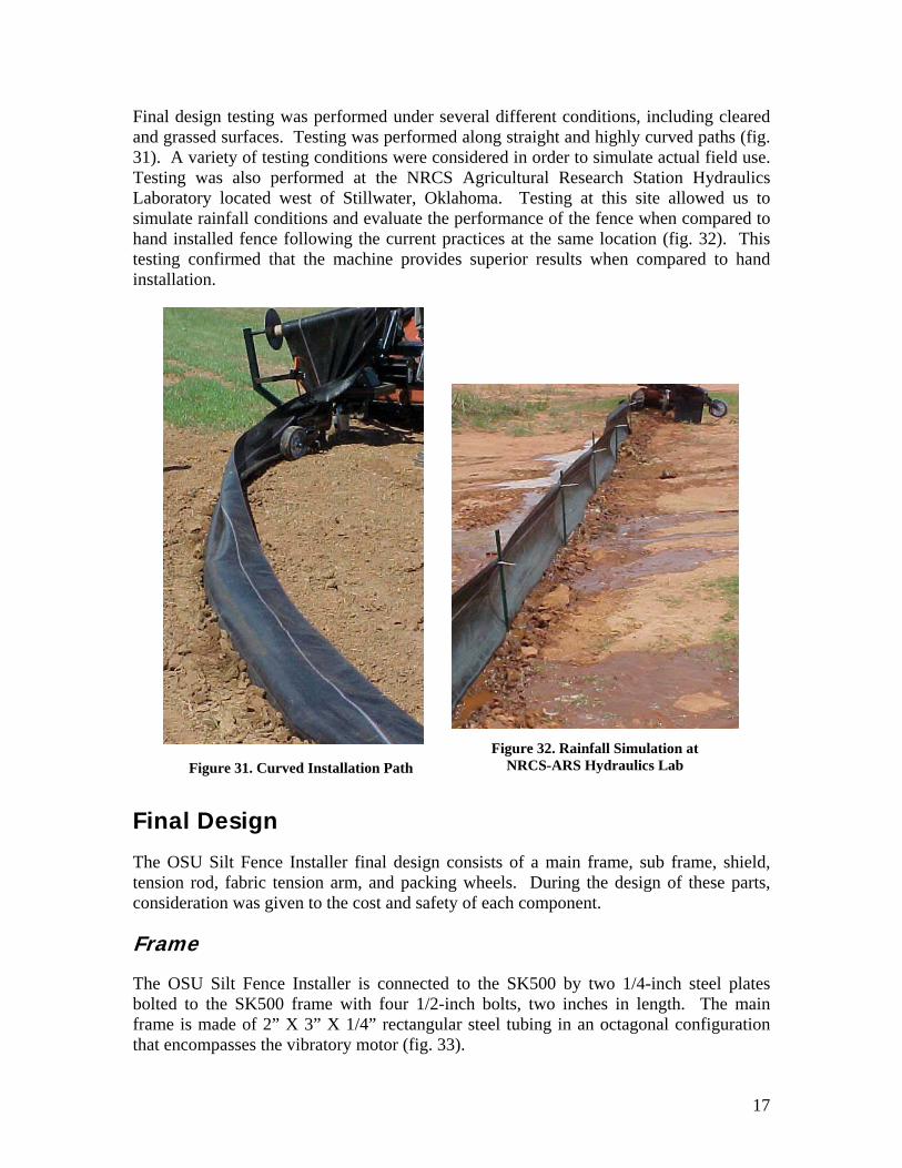
Final design testing was performed under several different conditions, including cleared and grassed surfaces. Testing was performed along straight and highly curved paths (fig. 31). A variety of testing conditions were considered in order to simulate actual field use. Testing was also performed at the NRCS Agricultural Research Station Hydraulics Laboratory located west of Stillwater, Oklahoma. Testing at this site allowed us to simulate rainfall conditions and evaluate the performance of the fence when compared to
sion arm, and packing wheels. During the design of these parts, consideration was given to the cost and safety of each component.
K500 frame with four 1/2-inch bolts, two inches in length. The main frame is made of 2” X 3” X 1/4” rectangular steel tubing in an octagonal configuration that encompasses the vibratory motor (fig. 33).
Fig 2. Rainfall Simulation at NRCS-ARS Hydraulics Lab
hand installed fence following the current practices at the same location (fig. 32). This testing confirmed that the machine provides superior results when compared to hand installation.
ure 3Figure 31. Curved Installation Path
Final Design
The OSU Silt Fence Installer final design consists of a main frame, sub frame, shield, tension rod, fabric ten
Frame
The OSU Silt Fence Installer is connected to the SK500 by two 1/4-inch steel plates bolted to the S
17

At the rear of the main frame, a pivot point allows the shield to follow the path of the blade (fig. 34). The sub-frame has a three-inch tall, 2.5-inch outer diameter bushing that is retained between to similar bushings on the main frame. This assembly is held in position by a two-inch pin. The main pin has a 3/4-inch hole through the center to accommodate a fastening pin. This fastening pin secures two plates that hold the main pin into location without transferring any of the sub-frame loading to the fastening pin. A grease zerk was added to the center collar for lubrication to reduce friction and wear on the pivot parts.
ates that connect to the pivot point (fig. ms and i unting
locations for the fabric roll, tension rod, and packing wheels lso incorpo the sub-frame.
A fabric roll support arm, made of 2” X 2” X 3/16” g, is welded to the sub frame. Welded to the support arm at 30 degree a one-inc tside diameter rod works much like a paper-towel dispens are pla the fabric rod and allowed to rotate as material is fed around the tension rod and into the shield. An adjustable, ten-inch diameter, 1/8-inch steel plate is added to the support arm. This round plate gives the roll of fabric a flat surface on which to rest for stability and provides adjustment for fabric position.
Figure 34. Exploded Vi of Main Pivot
Figure 33. Main Frame on SK500
ew
The sub-frame begins with two ½-inch steel pl35). The shield is nestled between these ar s welded in location. Mo
are a rated in
square steel tubins from horizontal,
brich ou
er. Rolls of fa ced on
18

To provide proper placement of the tension rod, a 1.5” X 1.5” X 3/16” tube was welded to the fabric support arm. A series of 1/4-inch parallel plates with 1/2-inch holes were used for a bracket that pins the tension rod in place. The packing wheel mount is a series of 3/8-inch plates with a 1-inch hole for a pivot pin connection.
Fabric Roll Support
Tension Rod Pivot
Packing Wheel Mount
Components
Due to c the original conically-shaped front of the shield was
front section of the shield ple V-shape knife edge. A
p /8-inch steel sheet metal, separated by 3 The shield keeps the soil slot open as
Figure 35. Sub-Frame mounted to Main Frame and SK500
Figure 36. Revised Shield
complexity and manufacturing ost,
revised (fig. 36). Thewas changed to a simcap at the bottom of the shield was also designed to prevent soil from entering and packing against the tension rod, as encountered during final testing. The body of the shield is made from two
ieces of 1/4-inch.
the tension rod directs the fence material into the trench.
19

The
thcuintoorshpihopirothth een properly loaded, the tension rod can be pinned into operating position inside the shield.
A fabric tension arm was constructed from a curved piece of 3/16-inch plate welded to a 1.5” X 1.5” X 3/16” tube (fig. 38). The plate matches the contour of a full roll of fabric. Carried on a spring-loaded arm, the plate presses on the fabric roll. Contact friction prevents the wind from unrolling the fabric.
created by the SK500. The position of the packing wheels effectively collects loose soil and compacts it near the installed fence. A
e tension rod was made from a curved 1/2-inch el rod that forms two-thirds of a circle with a
ree-foot diameter (fig. 37). Proper placement and rvature of the rod was critical for proper stallation of fabric. Two cross pieces were welded the inside upper portion of the circular rod in der to ensure rigidity. The rod was attached to the ield frame using a two-pin method. One of the ns acts as a pivot and the other spring-loaded pin lds the rod in place. This system allows the rod to vot in-and-out of the shield. Moving the tension d out of the shield enables convenient loading of e fabric during the start of fence installation. Once e fabric has b
st
Figure 37. Tension Rod
As stated in the design criteria, loose soil must be compacted in order to prevent undercutting. Two ten-inch diameter wheels were added, one on each side of the shield, in a staggered, toed-out position. Working together, the wheels provide the force needed for proper soil compaction. Down-pressure is
Figure 38. Fabric Tension Arm
20

three-position selection bracket allows the wheels to operate at depth settings of six, eight, and ten inches to gauge the installation depth of the fabric (fig. 39). The wheels also pivot outward to allow easy the fabric roll on the tension rod (fig. 40).
Operator’s Manual
After the final prototype was completed, an operator’s manual was created. The initial portion covered safety concerns. Sections regarding initial machine assembly, safe operating procedures, and troubleshooting were also included. The complete manual is included in Appendix B.
The design of operator of the machine at the end opposite t nents during operation. The controls also do not permit the operator
clicks itself into place, allowing the operator to keep hands clear when rotating the tension rod.
pth Selector Positions
loading of
Figure 39. De Figure 40. Packing Wheels
the SK500 locates the
he moving compo
to leave them without automatically disengaging the machine. The gap located between the moving vibratory plow casing and the main frame was design to be a full-inch wide to minimize the potential for pinched fingers. The second pinch point is the main pivot that allows the sub frame to swing behind the machine. These areas are clearly labeled with precautionary stickers. The final area of concern is the tension rod pivot point (fig. 41). To minimize risk a spring pin is used that Figure 41. Tension Rod Pivot Point
21

Project Schedule
Project scheduling was divided into two major sections, by semester. In each semester, ubtasks. During the fall semester, the main tasks ept Development, Investigation and Testing, and er continued those tasks, with the addition of Final ule was completed as planned, with the exception of he beginning of the spring semester. Concept testing feasibility study and Pro-Engineer modeling. Once plete, component procurement and final drafting
ed. Final testing of the prototype was completed and A detailed Gantt chart showing the entire fall and pendix C.
the schedule contained tasks and sincluded Project Definition, ConcDocumentation. The spring semestDesign and Drafting. The fall schedmethods testing, which occurred at twas completed concurrently with theconceptual developments were combegan. Prototype fabrication followa final drawing review performed. spring semesters can be found in Ap
Cost Analys
sed solely on the equipment use fee charged when components are fabricated in the Biosystems and Agricultural Engineering Laboratory. It did not include the machinists’ labor because that is covered by a different division of Oklahoma State University. A 20 percent contingency was added to both the material and fabrication charges to cover the cost of any concept components that may need to be constructed in addition to the final prototype.
Table 2. Silt Fence Installer Proposed Budget
Material Cost
Fabrication Time
Fabrication Cost
Total Cost
is
Prototype Budget
The budget was broken down into the four components of the machine (table 2). Material cost and manufacturing times for each component were estimated, based on industry experience. Fabrication cost was ba
Plow Blade $30.00 10 hr $24.00 $54.00 Frame Work $210.00 25 hr $60.00 $270.00
Feeding Mechanism $120.00 25 hr $60.00 $180.00
Packing Wheel $180.00 25 hr $60.00 $240.00 Total Cost $540.00 85 hr $204.00 $744.00
Prototype Fabrication Cost
The fabrication costs for the completed machine included costs for the various intermediate concept testing components. After finishing fabrication of the final prototype, the total cost for each of the areas was determined (table 3). Fabrication time for the frame work was underestimated. This was due to the multiple experimental variations built to finalize the pivot locations and the overall component layout and complexity of the welded assemblies. However, the cost of the packing wheels was
22
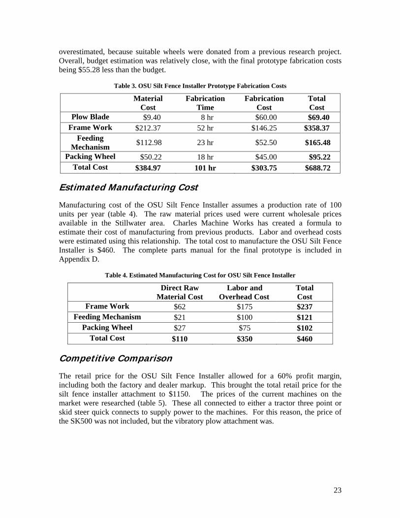
overestimated, because suitable wheels wOverall, budget estimation was relatively being $55.28 less than the budget.
Table 3. OSU Silt Fence Ins
Material Fa
ere donated from a previous research project. close, with the final prototype fabrication costs
taller Prototype Fabrication Costs
Cost brication Time
Fabrication Cost
Total Cost
Plow Blade $9.40 8 hr $60.00 $69.40 Frame Work $212.37 52 hr $146.25 $358.37
Feeding Mechanism $112.98 23 hr $52.50 $165.48
Packing Wheel $50.22 18 hr $45.00 $95.22 Total Cost $384.97 101 hr $303.75 $688.72
Estimated Manufacturing Cost
Manufacturing cost of the OSU Silt Fence Inunits per year (table 4). The raw maavail
staller assumes a production rate of 100 terial prices used were current wholesale prices
harles Machine ormula to estim m previous products. Labor and overhead costs
nship. The total cost to manufacture the OSU Silt Fence Installer is $460. The complete parts manual for the final prototype is included in
Direct Raw Material Cost
Labor and Overhead Cost
Total Cost
able in the Stillwater area. Cate their cost of manufacturing fro
Works has created a f
were estimated using this relatio
Appendix D.
Table 4. Estimated Manufacturing Cost for OSU Silt Fence Installer
Frame Work $62 $175 $237 Feeding Mechanism $21 $100 $121
Packing Wheel $27 $75 $102 Total Cost $110 $350 $460
Competitive Comparison
The retail price for the OSU Silt Fence Inincluding both the factory and dealer markupsilt fence installer attachment to $1150. Tmarket were researched (table 5). These allskid steer quick connects to supply power to the SK500 was not included, but the vibratory
staller allowed for a 60% profit margin, . This brought the total retail price for the he prices of the current machines on the
connected to either a tractor three point or the machines. For this reason, the price of plow attachment was.
23

Table 5. Price Comparison with Products Currently Available
Product Retail Price Tommy Silt Fence Machine $7177
McCormick Silt Fence Installer $4925 ImpleMax SF12c $11794
OSU Silt Fence Installer and Vibratory Plow Attachment $6400
Conclusion
Results of this project reflect the extent to which Enviro-Mech has accomplished the design criteria. The FAESF group required that the new equipment be compatible with their new fence design and that it does not promote installation related erosion. More
criteria provided by the FAESF group require that the new installing fence in a trench eight to ten inches deep,
w mpacted. Charles Machine Works, Inc. also provided design criteria which requ ign be compatible with current Ditch Witch
installation equipment installation depth of ei Soiwas another criterion th thinsta mpacte ng was o dete force re to rem from nch. Test results confi re place uiring an ge force of 45 pounds to pull the fence from the ground (f he r strated co ce with the criteria set by the FAESF research
C n e final prototype be compatible with their current v ed to attach to the SK500 vibratory plow. The
nstalled
specifically, the designinstallation equipment be capable of
ith soil backfilled and coired that the final des
vibratory plows and that the final prototype be economically feasible and marketable. Through the production of a prototype and extensive testing, these criteria have been measured. Results meet or exceed the sponsors’ requirements.
Considering the criteria set forth by the FAESF group, Enviro-Mech’s design performed well. Through final design testing we showed that the
Figure 42. I Fence
provided an average fence ght inches. met. Wi
l compaction e silt fence
d, testilled, backfilled, and performed t
the soil cormine the quired
ove the fence the trermed secu ment, req avera
ig. 42). All of t esults illu mplian group.
harles Machi e Works required that thibratory plows. A design was develop
SK500 was used throughout testing and proved to be capable of handling the weight and providing the power needed to operate the new installation attachment.
Second, Charles Machine Works asked that the new design be economically feasible. As an attachment, the final prototype met that criterion. Every effort was made to keep the cost of the new design profitable. For example, the original conically-shaped shield was changed to a V-shape to minimizing fabrication time.
24

Finally, Charles Machine Works asked that the final design be marketable. It should be competitive in the equipment market, based on
afety, and cost. roug field t the
final design has proven to be efficient. It has m he installatio ments he design criteria and operates at a speed desired by the operator. Operator safety was emparts were clearly labeled. Additional safety considerations have been addressed in the Operator’s Manual. Finally, the relative
production cost of the prototype makes it marketable. With low production costs, the
Figure 43. Final Prototype with Design Team
efficiency, operator sTh h extensive esting,
et all tn require stated in t
phasized. All moving
selling price is competitive with similar products currently being used.
25

Reference
Barfield, Billy J., K atlock “Effective
Stormwater eline tion Using a New Filter Fence d Petro vironmental Consortium.
Ditch Witch.
s
haled A. M. Gasem, and Marty Mand Sediment Control During Pip
. 2000. Construc
Conce tegrate
pt.” Proposal to In leum En
2001. Ditch Witch. Available at: http://www.ditchwitch.com/dwcom/ ccessed 14 Oct. 2003. index.jsp/. A
Erosion Runner. 2003. “Professional Silt Fence Installation.” Erosion Runner LTD. Erosion Runner, LTD., Cincinnati, Ohio. Available at: http://erosionrunner.com/. Accessed 14 Oct. 2003.
Implemax. 2003. “SF12c Silt Fence Installer.” Implemax Equipment Co., Inc. - Product Detail. Implemax Equipment Co., Inc., Bozeman, Montana. Available at: http://www.implemax.com/productsdetail.asp?ID=11/. Accessed 14 Oct. 2003.
McCormick. 2003. “Silt Fence and Waterway Fabric Installation Plow.” McCormick Equipment - Silt Fence Plow, Erosion control, Construction Equipment and More.
vailable at: .html. Accessed 14 Oct. 2003.
ets.
McCormick Equipment, Pleasantville, Iowa. Ahttp://mccormickequipment.com/siltfenceplow
NRCS. 2003. “Silt Fence Installation.” NRCS Fact She National Resource
on Control Services, Education,
Conservation Service.
Salix. 2000. “Effective Silt Fence Installation.” Erosiand Technology for the World. Salix Applied EAvailable at: http://www.salixaec.com/siltfence
Carpenter. 2003. “Perfect Installation – Why?” The
arthcare, Redding, California. .html. Accessed 14 Oct 2003.
Tommy Silt Fence Machine. ilable at: http://www.tommy-Carpenter Erosion Control, Ankeny, Iowa. Ava
sfm.com/. Accessed 14 Oct 2003.
26
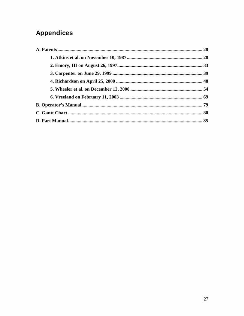
Appendices
.
1. Atkins et al. on November 10, 1987 .......
2. Emory, III on August 26, 1997...............
3. Carpenter on June 29, 1999 ..................
4. Richardson on April 25, 2000 ................
5. Wheeler et al. on December 12, 2000 ....
6. Vreeland on February 11, 2003 .............
B. Operator’s Manual.............................................
C. Gantt Chart .........
A. Patents ................................................................ ........................................................ 28
........................................................ 28
........................................................ 33
......................................................... 39
........................................................ 48
........................................................ 54
........................................................ 69
........................................................ 79
......................................................... 80
D. Part Manual................................................................................................................ 85
..............................................
27