
EFFECTIVE ELASTIC MODULI AND CHARACTERIZATION … Elastic... · sm report 93-31 effective elastic...
21
SM Report 93-31 EFFECTIVE ELASTIC MODULI AND CHARACTERIZATION OF A PARTICULATE-REINFORCED METAL MATRIX COMPOSITE WITH DAMAGED PARTICLES W. Tong and G. Ravichandran Graduate Aeronautical Laboratories California Institute of Technology Pasadena, California 91125
Transcript of EFFECTIVE ELASTIC MODULI AND CHARACTERIZATION … Elastic... · sm report 93-31 effective elastic...
SM Report 93-31
EFFECTIVE ELASTIC MODULI AND CHARACTERIZATION OF
A PARTICULATE-REINFORCED METAL MATRIX COMPOSITE
WITH DAMAGED PARTICLES
W. Tong
and
G. Ravichandran
Graduate Aeronautical Laboratories
California Institute of Technology
Pasadena, California 91125

EFFECTIVE ELASTIC MODULI AND CHARACTERIZATION OF A
PARTICULATE-REINFORCED METAL MATRIX COMPOSITE
WITH DAMAGED PARTICLES
W. Tong and G. Ravichandran
Graduate Aeronautical Laboratories
Division of Engineering and Applied Science
California Institute of Technology
Pasadena, California 91125
Abstract
A brief derivation of the expression is given for the effective bulk modulus of discontinuously
reinforced metal matrix composites (DMMCs) with damaged particles (either complete voids
as shattered particles or debonded particles). The analytical results are then compared with
elastic moduli determined from nondestructive ultrasonic wave speed measurements of SiC
particle-reinforced titanium matrix composites produced via shock wave consolidation. For
the shock consolidated Ti-SiC metal matrix composites compacts, the overall particle damage
mode is found to be similar to debonded particles and the effective volume fraction of
damaged particles is determined to be 39% based on the data of both Young's and bulk
moduli. Ultrasonic wave speed measurements combining with analytical and/or numerical
results on overall elastic properties (Young's, bulk, and shear moduli, and Poisson's ratio)
could be a useful tool in assessing the damage of particles in DMMCs.
1

1. INTRODUCTION
Fracture of reinforcement particles either during processing or during subsequent mechanical
loading have been observed experimentally in discontinuously particulate-reinforced metal
matrix composites (DMMCs).l-4 Characterization of damaged particles will be valuable in
improving processing procedures and in understanding deformation and failure of DMMCs.
The number of fractured particles can be measured using optical and electron microscopy and
particle fracture is found to be influenced by the size, shape, and spatial distribution of the
reinforcement particles. Even though the number of particles damaged in DMMCs is a very
useful information, the effect of damaged particles on elastic and other properties of DMMCs
is directly related to the effective volume fraction of those particles. Indirect methods such as
Wiebull statistical model can be used to calculated the effective volume from the number of
damaged particles;4-5 this approach is, however, inherently inaccurate. Surface damages are
common during preparation of DMMCs specimens for microscopy examination and some
microscopic cracks within particles may be difficult to detect.
Macroscopically, the damage of particles can also be assessed by comparing the overall elastic
moduli determined either by calculating the elastic unloading slope in a tensile test5 or by
measuring elastic ultrasonic wave speeds6 with predictions of existing analytical and/or
numerical models. There exists a rich literature of theoretical models in estimating overall
elastic properties of DMMCs when reinforcements are assumed to be perfectly bonded.1-8
Analytical results such as the Hashin-Shtrikman bounds,9 self-consistent estimates, 10 and
mean-filed theoriesll are found to be well applicable to DMMCs with randomly distributed
particles of low aspect ratio. Finite element analyses are also used to study the overall elastic
properties of two-phase DMMCs as a function of the shape, concentration, and spatial
distribution of the reinforcement particles.l2 Recently, analytical models of overall elastic
2

moduli of DMMCs with damaged particles have been formulated. 13 By combining Eshelby's
equivalent inclusion method and Mori-Tanaka's back stress analysis,l4-15 Mochida et af.13
obtained the analytical expressions of Young's modulus of DMMCs for three particle damage
models: the shattering of particles producing complete voids, debonding of at the interface
between the matrix and particles, and aligned penny-shaped cracks within particles. A
numerical study of Young's modulus of DMMCs with aligned penny-shaped cracks within
particles has also been reported.l2 However, the actual damage mode of particles cannot be
determined through these results on Young's modulus alone and thus the effective volume
fraction of damaged particle remains uncertain.
We propose here that for some DMMCs it is possible to determine both the overall damage
mode of particles and the effective volume fraction of damaged particles by including the
second elastic constant, the bulk modulus, in both experimental measurements and analytical
modeling. At first, we present a brief derivation of the expression for the effective bulk
modulus of DMMCs with damaged particles (either complete voids as shattered particles or
debonded particles) following the approach of Mochida et af.13 The analytical results are then
compared with elastic moduli determined from nondestructive ultrasonic wave speed
measurements of SiC particle-reinforced titanium matrix composites produced through shock
wave consolidation.l6 Based on the data of Young's modulus, the effective volume fraction of
damaged particles is estimated to be about 31%, 39%, and 46% for three particle damage
modes - complete voids, debonded particles, and particles containing aligned single penny
shaped cracks, respectively. The effective volume fraction of damaged particles is found to be
39% for either complete voids or debonded particles based on the data of bulk modulus.
Thus, for the shock consolidated Ti-SiC DMMCs, the overall particle damage mode is similar
3

to debonded particles and the effective volume fraction of damaged particle is determined to
be 39%.
2. ANALYTICAL MODELS
Following Taya and Chou 15 of using the combination of Eshelby's equivalent inclusion
method14 and Mori-Tanaka's back stress analysis, II Mochida et a/. 13 obtained the weakened
effective Young's modulus of particulate-reinforced DMMCs when some of particle
reinforcements are damaged. The composite is modeled as an infinite elastic body which
contains an infinite number of ellipsoidal inhomogeneities with two kinds (undamaged and
damaged particles). For the three cases of the shattering of particles producing complete
voids, debonded particles, and particles containing single penny-shaped cracks (Fig. 1), their
results can be summarized as
}1__ 1
E'" 1+Tip(l- h)fo +Tld.t;d;,' (1)
where Ec and Em are Young's moduli of the composite and matrix, respectively, / 0 is the
volume fraction of total particle reinforcements,fd is the volume fraction of damaged particles
in terms of total particles, and Tip and Tid are functions of / 0, fd and elastic moduli of matrix
and reinforcements (see the detailed expressions given by Mochida et af.l3).
The second elastic constant, the bulk modulus of the hybrid composites, can also obtained by
replacing the uniaxial tensile stress field of Mochiba et af.l3 with a hydrostatic tensile stress
field imposed on the composite. A brief derivation of the bulk modulus is presented here.
The overall stiffness of the composite is determined by using the equivalence of the strain
energies (see Eq. 10 in Mochida et af.l3),
4
(2)
where C~k/-1 and c;;k/-1
are the compliances of the matrix and the composite, respectively; cr~
is the applied stress, fv(=fJ0) is the volume fraction of damaged particles, f/=f0-fcf0) is the
volume fraction of undamaged particles, fo is the total volume fraction of reinforcement
particles (known for a given DMMC) andfd is the part of those particles damaged (in terms of
volume fraction). The details of the derivation of Eq. (2) are given by Taya and Chou15. e~·
and e;; in Eq. (2) are eigenstrains due to the existence of undamaged and damaged particles in
the matrix which can be determjned through equivalent inclusion method (see the details of
derivation of Esq. 1-9 in Mochida et af.l3),
(3)
(4)
(5)
(6)
where C!}~:1 is the stiffness of the reinforcement particle, e~1 is the strain disturbance in the
matrix without any reinforcements, e*1 is the averaged strain disturbance in the matrix due to
all undamaged and damaged reinforcement particles, e~ is the strain disturbance in the
undamaged particle, e;, is the strain disturbance in the damaged particle, s:lmn is Eshelby's
tensor for the undamaged particle which depends on C:;'t1 and the geometry of the particle, and
S~m" is Eshelby's tensor for the damaged particle. If damaged particles are represented as
spherical voids or de bonded particles, s:,m,. = s;,m,..
For a hydrostatic stress field,
cr~1 = cr~ = cr~ = cr0 , all other cr~ = 0, (7)
Eq. (2) is reduced to
5

(8)
where Kc and Km are bulk moduli of the composite and matrix, respectively, and Eq. (6) is
reduced to
(9)
where for spherical voids or debonded particles, we have (see Appendix A in Mochida et
af. l3)
where v m is the Poisson's ratio of the matrix. Subsequently, Eqs. (3-5) can be reduced to
cr0 + 3Kme + 3Km (S1 + 2S2 - 1)ev• = 0,
e + J;, (S1 + 2S2 -1)ep• +f. (S1 + 2S2 -1)ev• = 0,
where KP is the bulk modulus of the reinforcement
(10)
(11)
(12)
(13)
The bulk modulus of the composite can then be obtained by solving the eigenstrains in Eqs.
(11-13) and by substituting them into Eq. (8). The final result for the bulk modulus is given as
}(c 1 -= ' }(m 1 + 3TI.t(l- fd)fo + 3TIJJo
(14)
where ll.t and llv are functions of f 0, fd, and elastic constants of matrix and reinforcements,
namely,
1 (15) ll.t = }( s - }( ( s - 1) , 3(1-Jd ).fo(S - 1)+3(/.d~-1) p m
}(P- }(m
6
(16)
(17)
3. APPLICATION OF ANALYTICAL RESULTS AND DISCUSSIONS
Due to their excellent high temperature properties, Ti-SiC metal matrix composites have been
considered to be a potential structural material in aerospace industry.l7 These materials are
generally difficult to produce using traditional diffusion bonding or hot-press methods because
of the high reactivity of Ti with most reinforcement materials. 18 Recently, Ti-SiC particulate
reinforced metal matrix composites have thus been processed by shock wave
consolidation.2,16 The extremely high pressure and short process time (on the order of a
microsecond) achieved during shock consolidation have made it feasible to obtain fully
dense compacts with a minimum of inteifacial reactions. Subsequent heat treatments of the
composites can produce controlled interfacial reaction zone sizes. The processed materials
are ideal for studying effects of interfacial properties on the mechanical behavior of particulate
reinforced metal matrix composites.
Particulate reinforced Ti-SiC metal matrix composites were fabricated with the Keck
Dynamic Consolidation Facility. The facility is built around a 3 meter long and 35 mm in
diameter smooth bore cannon barrel supplied through the courtesy of Aerojet Ordinance.
The propellant cannon was designed specifically for one-dimensional plane shock wave
7
consolidation and recovery of materials.19 Three types of titanium-SiC composite powders
were used: Type I and Type II titanium-SiC composite powders were obtained by blending
the corresponding pure titanium powder (particle sizes of -100 mesh and -325 mesh
respectively) with 10% volume fraction of #600 SiC powder with an average particle size of
12 J..Lm (Electro-Abrasive, Inc.). Type III composite powder was obtained by ball-milling of
the -325 mesh titanium powder plus 10% vol. #600 SiC powder for 9 hours (resulting the
average size of SiC is about 1-2 J..Lm). Before consolidation, Types I and II powders were
degassed for six hours and Type III powder was degassed for twelve hours at 600°C in a
vacuum of 5x10⁻⁶ Torr. The degassed powder was transferred directly into an argon-fllled
glovebox without being exposed to the laboratory atmosphere. Packing of powder into the
target fixture was conducted in the sealed glovebox and the powder was sealed with a thin
aluminum foil at the top of the target. The thin aluminum foil reduces oxygen and other gas
contaminations during installation of the target into the compactor chamber. After flushing
the gun barrel with argon gas, the gun barrel was pumped to a vacuum of about 25 mTorr
causing the thin aluminum foil to break off and allow proper degassing of packed powder
before shock consolidation. A 31.5 mm diameter flyer plate is mounted onto a nylon sabot
and accelerated by smokeless shotgun or pistol powder. Ayer speeds of up to 2 km/s can be
obtained. The densification of the powders is accomplished by the passage of a strong shock
wave generated upon the impact of flyer onto the green compact (target powder).
Fully dense composite compacts (31-32 mm in diameter and 7-8 mm in height) have been
obtained that are free from interfacial reactions and macroscopic cracks (Fig. 2a). Assuming
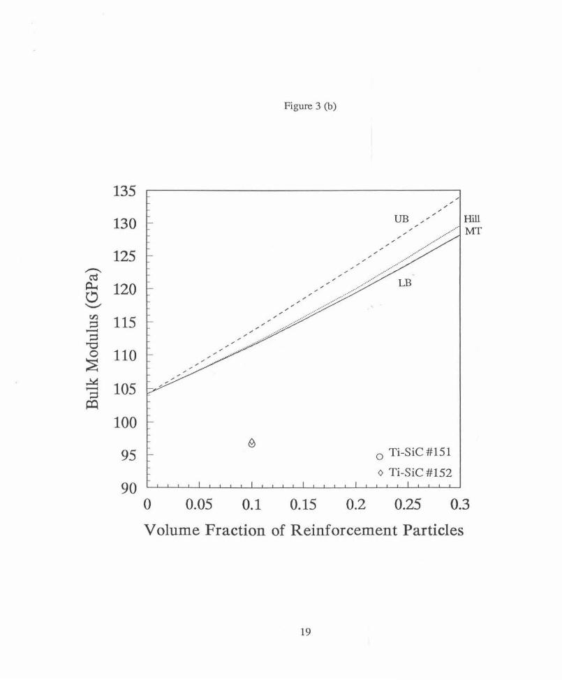
Young's modulus £=450 GPa and 110 GPa, Poisson's ratio u=0.17 and 0.324 for SiC
particles and titanium matrix respectively, the Hashin-Shtrikman bounds9 for both Young's
modulus and bulk modulus of 10% vol. undamaged SiC particle reinforced titanium matrix
8

composites are 124.8 GPa ;S; E ;S; 133.1 GPa, 111.3 GPa ;S; K ;S; 113.6 GPa. Self-consistent
estimateslO are £=125.3 GPa and K=111.4 GPa. Mori-Tanaka's mean field theoryll gives
£=124.9 GPa and K=l11.4 GPa. Figs. 3 (a) and (b) show results of Young's and bulk moduli
of Ti-SiC composites by Hashin-Shtrikman variational method, self-consistent scheme, and
Mori-Tanaka mean field theory for different volume fraction of reinforcements. Results of
elastic moduli of composite compacts #151 and #152 are also shown in Figs. 3 (a) and (b)
based on measurements of ultrasonic wave speeds.t6 The composite compacts #151 and
#152 were made of Type I and Type ll titanium-SiC powders respectively.
The existence of some microscopic defects in composite compacts #151 and #152 can be
indirectly deduced from the much lower-than-expected effective overall elastic moduli of these
composites (both the Young's modulus and bulk modulus of compacts #151 and #152 are
outside the Hashin-Shtrikman lower bounds). The micrographs of these composites show
some fracture and damage of large SiC particles (Fig. 2b). Also, the bonding between SiC
particles and surrounding titanium matrix may not be perfect as well (note nearly zero
interfacial reaction). It is clear that fracture of the SiC particles occurs during shock
consolidation because of the high pressures present and/or thermal contraction mismatch upon
subsequent cooling to room temperature. In addition, the SiC particles have irregular shapes
and may have some preexisting internal defects. Number fractions of cracked particles in
shock consolidated composites compacts were reported to range from 90% for a large
average SiC particle size of 104 flm to 5% for a small average SiC particle size of 12 flm2
SiC particles with a small average size of 12 flm are used in composite compacts #151 and
#152.
9

An estimate of the volume fraction of damaged particles in composite compacts can be made
by applying the analytical results for Young's modulus of DMMCs by Mochida et a/. 13 and for
bulk modulus given above (Eqs. 14-17). The composite is assumed to consist of titanium
matrix, perfectly bonded spherical SiC particles, and spherical voids or debonded SiC particles
(replacing fractured SiC particles). The Young's and bulk moduli of such composites can be
computed for a given volume fraction of perfectly bonded SiC particles and spherical voids or
debonded SiC particles. The results for 10% vol. SiC particulate reinforced titanium
composites are shown in Fig. 4. Even though only about 5-10 % of SiC particles were
microscopically observed to be apparently fractured in the as-consolidated compacts #151 and
#152, the effective volume fraction of damaged particles can be much higher because larger
particles are more prone to fracture and a lot of microcracks may exist. From the plots shown
in Fig. 4, the model of debonded SiC particles is found to be a fairly good representation of
damaged SiC particles and the estimated volume fraction of damaged SiC particles is about
39% in compacts #151 and #152. For compact #154 made of Type III titanium-SiC powder
with a much smaller average size of SiC particles (1-2 !J.m), its Young's modulus is within the
Hashin-Shtrikman bounds and its bulk modulus is very close to the lower bound which
indicated that smaller SiC particle reinforcements (1-2j..tm) would cause much less or virtually
no cracking of particles.l6
In summary, large particles were found prone to crack in shock consolidated Ti-SiC DMMCs.
While only about up to 10% of particles were observed microscopically damaged in composite
compacts, the effective volume fraction of damaged particles was estimated to be about 39%.
Cracked particles have effects on elastic moduli similar to that of debonded particles, namely,
there is still some constrains on uniaxial deformation of the matrix imposed by those damaged
particles. Ultrasonic wave speed measurements combining with analytical and/or numerical
10
results on overall elastic properties (Young's, bulk and shear moduli and Poisson's ratio) could
be a useful tool in assessing the damage of particles in DMMCs.
Acknowledgment-The authors would like to acknowledge the support of this research by the
Division of Materials Research of the National Science Foundation through grant #DMR-
9116570. G.R. acknowledges the support of an NSF Presidential Young Investigator award,
grant #MSS-9157846.
11

REFERENCES
1. J . Yang, C. Cady, M.S. Hu, F. Zok, R. Mehrabian and A.G. Evans, Effects of damage on the flow strength and ductility of a ductile Al alloy reinforced with SiC particulates, Acta Metal/. Mater., 38 (1990), pp. 2613-19.
2. T . Christman, K. Heady and T. Vreeland, Jr., Consolidation of Ti-SiC particle-reinforced metal-matrix composites, Scripta Metal/. Mater., 25 (1991), pp. 631-6.
3. D.J. Lloyd, Aspects of fracture in particulate reinforced metal matrix composites, Acta Metal/. Mater., 39 (1991), pp. 59-71.
4. Y. Brechet, J.D. Embury, S. Tao and L. Luo, Damage initiation in metal matrix composites, Acta Metal/. Mater., 39 (1991), pp. 1781-6.
5. T. Mochida, M. Taya and D.J. Lloyd, Fracture of particles in a particle/metal matrix composite under plastic straining and its effect on the Young's modulus of the composites, Mat Trans. , JIM, 32 (1991), pp. 931-42.
6. H. Ledbetter and S. Datta, Elastic constants of a tungsten-particle copper-matrix composite, JSME Inti. J., Series I, 34 (1991), pp. 194-7.
7. N. Laws, The elastic response of composite materials, in: Physics of Modern Materials, 1, pp. 465-520, International Atomic Energy Agency, Vienna, 1980.
8. S. Nemat-Nasser and M. Hori, Micromechanics: Overall Properties of Heterogeneous Materials, North-Holland series in Applied Mathematics and Mechanics, vol. 137, Elsevier Science Publishers B.V., Amsterdam, The Netherlands, 1993.
9. Z. Hashin and S. Shtrikman, A variational approach to the theory of the elastic behavior of multiphase materials, J. Mech. Phys. Solids, 11 (1963) , pp. 127-41.
10. R. Hill, A self-consistent mechanics of composite materials, J. Mech. Phys. Solids, 13 (1965), pp. 213-7.
11. T. Mori and K. Tanaka, Average stress in matrix and average elastic energy of materials, Acta Meta/1., 21 (1973), pp. 571-4.
12. Y.-L. Shen, M. Finot, A. Needleman and S. Suresh, Effective elastic response of twophase composites, Technical Report, Division of Engineering, Brown University, 1993.
12

13. T . Mochida, M. Taya and M. Obata, Effect of damaged particles on the stiffness of a particle/metal matrix composite, JSME Inti. J ., Series I, 34 (1991), pp. 187-93.
14. J.D. Eshelby, The determination of the elastic field of an ellipsoidal inclusion and related problems, Proc. Royal Soc. (London), A241 (1957), pp. 376-91.
15. M. Taya and T.-W. Chou, On two kinds of ellipsoidal inhomogeneities in an infinite elastic body: an application to a hybrid composite,lnt. J. Solids Structures, 17 (1981), pp. 553-63.
16. W. Tong, G. Ravichandran, T . Christman and T. Vreeland, Jr. , Processing SiC-particulate reinforced titanium-based metal matrix composites by shock wave consolidation, submitted to Acta Metal/. Mater. (1 993).
17. C. Ruffles, Applications of advanced composites in gas turbine aero engines, in: Proc. 9th Inti. Conf. on Composites Mater. (ICCM/9), Vol. 1, Metal Matrix Composites, A. Miravele (ed.), pp. 123-30, University ofZarogaza, Spain, 1993.
18. M.H. Loretto and T.P. Johnson, Microstructural observations of reaction zones inTibased metal matrix composites,]. Microscopy, 169 (1993), pp. 131-8.
19. A. Mutz and T. Vreeland, Jr., Several techniques for one-dimensional strain shock consolidation of multiple cavities, in: Shock Wave and High-Strain-Rate Phenomena in Materials, M.A. Meyers, L.E. Murr, and K. P. Staudharnmer (eds.), pp. 425-31, Marcel Dekker, Inc., New York, 1992.
13

LIST OF FIGURES
Figure 1
Schematic of three particle damage modes in metal matrix composites reinforced with
spherical particles.l3
Figure 2
Micrographs of shock consolidated SiC particulate-reinforced titanium metal matrix
composites: (a) Distribution and size of SiC particles in the composite compact #152; (b)
Cracking of some reinforcement particles.
Figure 3
Overall elastic Young's modulus (a) and bulk modulus (b) of Ti-SiC composites (both
theoretical predictions and experimental measurements): UB - Hashin-Shtrikman upper
bound;9 LB - Hashin-Shtrikman lower bound;9 Hill- Hill's self consistent estimate; 10 and
MT- Mori-Tanaka mean field theory.ll
Figure 4
Determination of the overall effective particle damage mode and effective volume fraction of
damaged particles in shock consolidated Ti-SiC composites.
14

debonded particles
nondamaged particle
Figure 1
shattering of particles
• nondamaged particle
(a) shattered particles producing complete voids.
cracking of particles
nondamaged particle
(b) particles with the debonded interface producing debonded particles.
(c) cracked particles producing penny-shaped cracks within the particles.
15

Figure 2 (a)
\ -~ :·' ~ . \"' : ...,, t ~ ... ::' ·, " ' ' '~\./-:·' ~~ -- ~" . . -\"' . .. ~· - ----~
\ • ~ ,' • I ~it ' • ,: . t ~- , ,_. • :· :.· • .• .:. .:. • · - -- 1! -·~ .,. . ~ ,. ,~.. . ~ ' ..... . . ·rr . , ,, " I ~-~ :-- r ' . ' • ., '
_l' • ' 1 \ , "'\. • .
;">,' .... ~ • ' .... . ~-- ,. , .. A...~ ..... ._., - .... --. "' -.· . \.~ • -. . . .. - . ' ' ~ , . . r l \'·'"--'· ' ' ..... _ . _,:,;~ \. ·'
:;' :---- . ... -·- ~ ... . ·' . . ~;- .. • . ·J! -~ .• ·: . _\ ~f-. <*' # · ... • ... ; '·: /T1.
16

Figure 2 (b)
. . /
" ' . \
17

180
...-.. C\S
~ 160
fJ)
... 00 1=1 ;::::i 0
~ 120
100 0
/
/ /
0.05
/
/ /
/ /
/ /
/ /
/ .. ·· ,"' .... ··
0.1
Figure 3 (a)
/ /
/ /
/
/ /
/ /
/ /
/ /
/
/ /
/
VB ,"
/ /
/ /
/
/ /
Hill .. ··········· MT
// ::·' '
.... ···· ., ;
.... ··· .,"" LB .... ·····:·.,.;,
.··· ,.. .··· / /
/ .·· /
... ·····~· ........ .··· / ... ····.,. ....
.·····.::<·· ~ ..... · ......
0.15 0.2
o Ti-SiC #151 0 Ti-SiC #152
0.25 0.3
Volume Fraction of Reinforcement Particles
18
135
130
125 .-._
C'd ~ 120 t) '-" en 115 :::i -:::i
"'CJ 0 110 ~ ~ 105 -;::::1 ~
100
95
90
Figure 3 (b)
0 0.05 0.1 0.15 0.2
/
/
"'
/ "' /
UB ,. .. "' Hill
/
"'
"' "' "' _, .. ············· MT
0 Ti-SiC #151
o Ti-SiC #152
0.25 0.3
Volume Fraction of Reinforcement Particles
19

135
125 .,-.
C'd A-c d 115 ......._, fJ)
;::::1 .....-4
;:::::1 105 '"d
0 ;E u
• ,.....j
~ 95 fJ)
C'd .....-4
~
85
75 0
Figure 4
E
'<-:·:······································ .... ···-...
········· ...
0 Ti-SiC #151 0 Ti-SiC#l52
0.2 0.4 0.6
···· ... ....
···············... (c)
······························· ...
0.8 1
Volume Fraction of Damaged Particles
20


