
effective date of November 1, 2017. - com.ohio.gov 93 OPC Adoption Announce… · plumbing drainage...
243
Ohio Board of Building Standards 6606 Tussing Road PO Box 4009 Reynoldsburg, OH 43068-9009 U.S.A. Gerald O. Holland, Chairman An Equal Opportunity Employer and Service Provider 614 | 644 2613 Fax 614 | 644 3147 TTY/TDD 800 | 750 0750 www.com.ohio.gov June 2017 At its meeting on May 26, 2017, the Ohio Board of Building Standards adopted the rule changes identified as Amendments Group 93. These rule amendments were adopted with an effective date of November 1, 2017. Amendments Group 93 includes the amended Ohio Plumbing Code (OPC) rules shown below. For your use, the complete text of each rule can be found following this coversheet and a summary of the significant changes can be found at the end of the rule pages. Rule Number OPC Chapter Chapter Title Effective date 4101:3-1-01 1 Administration. November 1, 2017 4101:3-2-01 2 Definitions. November 1, 2017 4101:3-3-01 3 General regulations. November 1, 2017 4101:3-4-01 4 Fixtures, faucets and fixture fittings. November 1, 2017 4101:3-5-01 5 Water heaters. November 1, 2017 4101:3-6-01 6 Water supply and distribution. November 1, 2017 4101:3-7-01 7 Sanitary drainage. November 1, 2017 4101:3-8-01 8 Indirect/special waste. November 1, 2017 4101:3-9-01 9 Vents. November 1, 2017 4101:3-10-01 10 Traps, interceptors and separators. November 1, 2017 4101:3-11-01 11 Storm drainage. November 1, 2017 4101:3-12-01 12 Special piping and storage systems. November 1, 2017 4101:3-13-01 13 Nonpotable water systems. November 1, 2017 4101:3-14-01 14 Subsurface landscape irrigation systems. November 1, 2017 4101:3-15-01 15 Referenced standards. November 1, 2017 Reason for Changes: The Board amended the Ohio Administrative Code Chapters 4101:3-1 to 4101:3-15 (rescind and adopt new) to comply with the five year rule review and to update the current Ohio Plumbing Code to reflect the 2015 edition of the “International Plumbing Code” with Ohio amendments. If you should have any questions regarding these rule changes, please call BBS staff at (614)644-2613.
Transcript of effective date of November 1, 2017. - com.ohio.gov 93 OPC Adoption Announce… · plumbing drainage...
Ohio Board of Building Standards 6606 Tussing Road PO Box 4009 Reynoldsburg, OH 43068-9009 U.S.A.
Gerald O. Holland, Chairman
An Equal Opportunity Employer and Service Provider
614 | 644 2613 Fax 614 | 644 3147 TTY/TDD 800 | 750 0750 www.com.ohio.gov
June 2017 At its meeting on May 26, 2017, the Ohio Board of Building Standards adopted the rule changes identified as Amendments Group 93. These rule amendments were adopted with an effective date of November 1, 2017. Amendments Group 93 includes the amended Ohio Plumbing Code (OPC) rules shown below. For your use, the complete text of each rule can be found following this coversheet and a summary of the significant changes can be found at the end of the rule pages. Rule Number OPC Chapter Chapter Title Effective date 4101:3-1-01 1 Administration. November 1, 2017 4101:3-2-01 2 Definitions. November 1, 2017 4101:3-3-01 3 General regulations. November 1, 2017 4101:3-4-01
4 Fixtures, faucets and fixture fittings.
November 1, 2017
4101:3-5-01 5 Water heaters. November 1, 2017 4101:3-6-01
6 Water supply and distribution.
November 1, 2017
4101:3-7-01 7 Sanitary drainage. November 1, 2017 4101:3-8-01 8 Indirect/special waste. November 1, 2017 4101:3-9-01 9 Vents. November 1, 2017 4101:3-10-01
10 Traps, interceptors and separators.
November 1, 2017
4101:3-11-01 11 Storm drainage. November 1, 2017 4101:3-12-01
12 Special piping and storage systems.
November 1, 2017
4101:3-13-01 13
Nonpotable water systems.
November 1, 2017
4101:3-14-01 14
Subsurface landscape irrigation systems.
November 1, 2017
4101:3-15-01 15 Referenced standards. November 1, 2017 Reason for Changes: The Board amended the Ohio Administrative Code Chapters 4101:3-1 to 4101:3-15 (rescind and adopt new) to comply with the five year rule review and to update the current Ohio Plumbing Code to reflect the 2015 edition of the “International Plumbing Code” with Ohio amendments. If you should have any questions regarding these rule changes, please call BBS staff at (614)644-2613.

4101:3-1-01 Administration.
[Comment: When a reference is made within this rule to a federal statutory provision, an industry consensus standard, or any other technical publication, the specific date and title of the publication as well as the name and address of the promulgating agency are listed in rule 4101:3-15-01 of the Administrative Code. The application of the referenced standards shall be limited and as prescribed in section 102.5 of rule 4101:1-1-01 of the Administrative Code.]
SECTION 101 GENERAL
101.1 Title. Chapters 4101:3-1 to 4101:3-15 of the Administrative Code shall be designated as the “Ohio Plumbing Code” for which the designation “OPC” may be substituted. The “International Plumbing Code 2015, first printing, Chapters 2 to 15,” as published by the “International Code Council, Inc.” is used as the basis of this document. References in these chapters to “this code” or to the “plumbing code” in other sections of the Administrative Code shall mean the “Ohio Plumbing Code”.
101.2 Scope. The provisions of this code shall apply to the design, installation, maintenance, alteration, repair, relocation, replacement, addition to, use and inspection of plumbing systems within buildings. This code shall also apply to those other systems, system components, equipment and appliances specifically addressed herein. 101.3 Administrative and enforcement. For administrative and enforcement provisions of this code, refer to sections 101.2 to 115.4 of the building code.
101.4 Referenced standards. When a reference is made within the plumbing code to a federal statutory provision, an industry consensus standard, or any other technical publication, the specific date and title of the publication as well as the name and address of the promulgating agency are listed in Chapter 15 of this code. The application of the referenced standards shall be limited and as prescribed in Section 102.5 of the building code.
ACTION: Final DATE: 05/26/2017 2:37 PM
RB p(170947) pa(315228) d(672526) ra(523784) print date: 05/31/2017 2:37 PM

Replaces: 4101:3-1-01
Effective: 11/01/2017
Five Year Review (FYR) Dates: 11/01/2022
CERTIFIED ELECTRONICALLY
Certification
05/26/2017
Date
Promulgated Under: 119.03Statutory Authority: 3781.10(A)Rule Amplifies: 3781.10, 3781.11, 3791.04Prior Effective Dates: 7/1/95, 3/1/98, 1/1/02, 3/1/05, 7/1/07, 11/1/11
4101:3-1-01 2

4101:3-2-01 Definitions. [Comment: When a reference is made within this rule to a federal statutory provision, an industry consensus standard, or any other technical publication, the specific date and title of the publication as well as the name and address of the promulgating agency are listed in rule 4101:3-15-01 of the Administrative Code. The application of the referenced standards shall be limited and as prescribed in section 102.5 of rule 4101:1-1-01 of the Administrative Code.]
SECTION 201 GENERAL
201.1 Scope. Unless otherwise expressly stated, the following words and terms shall, for the purposes of this code, have the meanings shown in this chapter. 201.2 Interchangeability. Words stated in the present tense include the future; words stated in the masculine gender include the feminine and neuter; the singular number includes the plural and the plural the singular. 201.3 Terms defined in other codes. Where terms are not defined in this code and are defined in the building code, fire code, “International Fuel Gas Code” or the mechanical code, such terms shall have the meanings ascribed to them as in those codes. 201.4 Terms not defined. Where terms are not defined through the methods authorized by this section, such terms shall have ordinarily accepted meanings such as the context implies.
SECTION 202 GENERAL DEFINITIONS
ABOVE-GROUND STORAGE TANK. A vessel, intended for fixed installation above grade, at grade, or below grade without backfill, used for the purpose of bulk storage, dispensing, handling or processing of hazardous, flammable or combustible liquids or gases and not connected to and utilized for the operation of building service equipment. ACCEPTED ENGINEERING PRACTICE. That which conforms to accepted principles, tests or standards of nationally recognized technical or scientific authorities. Where a standard is referred to in Chapter 4101:3-13 of the Administrative Code relative to “accepted engineering practice,” conformity to the applicable technical provisions, requirements, recommendations, and
ACTION: Final DATE: 05/26/2017 2:37 PM
RB p(170947) pa(315228) d(672527) ra(523783) print date: 05/31/2017 2:39 PM

4101:3-2-01 2
determinations in the standard or other publications is prima-fascia evidence of conformity with accepted engineering practice. ACCESS (TO). That which enables a fixture, appliance or equipment to be reached by ready access or by a means that first requires the removal or movement of a panel, door or similar obstruction (see “Ready access”). ACCESS COVER. A removable plate, usually secured by bolts or screws, to permit access to a pipe or pipe fitting for the purposes of inspection, repair or cleaning. ADAPTER FITTING. An approved connecting device that suitably and properly joins or adjusts pipes and fittings that do not otherwise fit together. AIR ADMITTANCE VALVE. One-way valve designed to allow air to enter the plumbing drainage system when negative pressures develop in the piping system. The device shall close by gravity and seal the vent terminal at zero differential pressure (no flow conditions) and under positive internal pressures. The purpose of an air admittance valve is to provide a method of allowing air to enter the plumbing drainage system without the use of a vent extended to open air and to prevent sewer gases from escaping into a building. AIR BREAK (Drainage System). A piping arrangement in which a drain from a fixture, appliance or device discharges indirectly into another fixture, receptacle or interceptor at a point below the flood level rim and above the trap seal. AIR GAP (Drainage System). The unobstructed vertical distance through the free atmosphere between the outlet of the waste pipe and the flood level rim of the receptacle into which the waste pipe is discharging. AIR GAP (Water Distribution System). The unobstructed vertical distance through the free atmosphere between the lowest opening from any pipe or faucet supplying water to a tank, plumbing fixture or other device and the flood level rim of the receptacle. ALTERNATE ON-SITE NONPOTABLE WATER. Nonpotable water from other than public utilities, on-site surface sources and subsurface natural freshwater sources. Examples of such water are gray water, on-site reclaimed water, collected rainwater, captured condensate and rejected water from reverse osmosis systems. Private water supplies and recycled water systems are regulated by the Ohio Department of Health rules found in Chapter 3701-28 of the Administrative Code. ALTERNATIVE ENGINEERED DESIGN. A plumbing system that performs in accordance with the intent of Chapters 3 through 12 and provides an equivalent level of performance for the protection of public health, safety and welfare. The system design is not specifically regulated by Chapters 3 through 12 in accordance with the requirements of section 106 of the building code. ANCHORS. See “Supports.” ANTISIPHON. A term applied to valves or mechanical devices that eliminate

4101:3-2-01 3
siphonage. APPROVED. Determined to be in compliance by the authority having jurisdiction in accordance with the rules of the board. APPROVED AGENCY. An established and accredited testing laboratory, listing agency, inspection body, or field evaluation body recognized by the board of building standards providing services consistent with their accreditation and the code section requiring the approved agency service. AREA DRAIN. A receptacle designed to collect surface or storm water from an open area. ASPIRATOR. A fitting or device supplied with water or other fluid under positive pressure that passes through an integral orifice or constriction, causing a vacuum. Aspirators are also referred to as suction apparatus, and are similar in operation to an ejector. BACKFLOW. Pressure created by any means in the water distribution system, which by being in excess of the pressure in the water supply mains causes a potential backflow condition.
Backpressure, low head. A pressure less than or equal to 4.33 psi (29.88 kPa) or the pressure exerted by a 10-foot (3048 mm) column of water. Backsiphonage. The backflow of potentially contaminated water into the potable water system as a result of the pressure in the potable water system falling below atmospheric pressure of the plumbing fixtures, pools, tanks or vats connected to the potable water distribution piping. Drainage. A reversal of flow in the drainage system. Water supply system. The flow of water or other liquids, mixtures or substances into the distribution pipes of a potable water supply from any source except the intended source.
BACKFLOW CONNECTION. Any arrangement whereby backflow is possible. BACKFLOW PREVENTER. A backflow prevention assembly, a backflow prevention device or other means or method to prevent backflow into the potable water supply. CONTAINMENT BACKFLOW PREVENTION DEVICE. A device for the prevention of the backflow of liquids, solids, or gases that is installed by the supplier of, or as a requirement of, any public water system as defined in division (A) of section 6109.01 of the Revised Code. ISOLATION BACKFLOW PREVENTION DEVICE. A device for the prevention of the backflow of liquids, solids, or gases that is regulated by the plumbing code adopted pursuant to section 3781.10 of the Revised Code and rules adopted pursuant to this section. See “Backflow Preventer”. BACKWATER VALVE. A device or valve installed in the building drain or sewer pipe where a sewer is subject to backflow, and that prevents drainage or waste from backing up into a lower level or fixtures and causing a flooding

4101:3-2-01 4
condition. BASE FLOOD ELEVATION. A reference point, determined in accordance with the building code, based on the depth or peak elevation of flooding, including wave height, which has a 1 percent (100-year flood) or greater chance of occurring in any given year. BATHROOM GROUP. A group of fixtures consisting of a water closet, lavatory, bathtub or shower, including or excluding a bidet, an emergency floor drain or both. Such fixtures are located together on the same floor level. BEDPAN STEAMER OR BOILER. A fixture utilized for scalding bedpans or urinals by direct application of steam or boiling water. BEDPAN WASHER AND STERILIZER. A fixture designed to wash bedpans and to flush the contents into the sanitary drainage system. Included are fixtures of this type that provide for disinfecting utensils by scalding with steam or hot water. BEDPAN WASHER HOSE. A device supplied with hot and cold water and located adjacent to a water closet or clinical sink to be utilized for cleansing bedpans. BRANCH. Any part of the piping system except a riser, main or stack. BRANCH INTERVAL. A vertical measurement of distance, 8 feet (2438 mm) or more in developed length, between the connections of horizontal branches to a drainage stack. Measurements are taken down the stack from the highest horizontal branch connection. BRANCH VENT. A vent connecting one or more individual vents with a vent stack or stack vent. BUILDING. Any structure consisting of foundations, walls, columns, girders, beams, floors, and roof, or a combination of any number of these parts, with or without other parts or appurtenances. See division (C)(2) of section 3781.06 of the Revised Code. BUILDING CODE. The “Ohio Building Code”. BUILDING DRAIN. That part of the lowest piping of a drainage system that receives the discharge from soil, waste and other drainage pipes inside and that extends 30 inches (762 mm) in developed length of pipe beyond the exterior walls of the building and conveys the drainage to the building sewer.
Combined. A building drain that conveys both sewage and storm water or other drainage. Sanitary. A building drain that conveys sewage only. Storm. A building drain that conveys storm water or other drainage, but not sewage.
BUILDING OFFICIAL. The superintendent of the division of industrial compliance of the Ohio department of commerce or the person appointed by the superintendent to enforce this code in that division, or the designated authority
4101:3-2-01 5
charged with the administration and enforcement of this code, approved by the board in accordance with section 103 of this code, in a municipal corporation, township or county having a building department, certified by the board pursuant to section 3781.10 of the Revised Code, or the health commissioner or his authorized representative in health districts, whichever one has jurisdiction.
BUILDING SERVICE EQUIPMENT. Equipment, appliances, materials, devices, and systems integrated into a building that provide space heating, air conditioning, ventilation, fire protection, lighting, electricity, sanitation, water, water heating, cooking, medical gas, medical vacuum, and clothes drying. Building service equipment begins from the connected stored source of liquid or gas fuel or electrical power supplying the equipment or the utility service point/point of delivery and extends through the point of use but does not include process equipment that may also be connected to the same source. BUILDING SERVICES PIPING. All piping systems and their component parts that are part of a building system and that promote the safe, sanitary, and energy efficient occupancy of a building. Building services piping includes, but is not limited to, cold and hot potable water distribution for plumbing fixtures; sanitary lines from plumbing fixtures; nonflammable medical gas systems; medical oxygen systems; medical vacuum systems; fire protection piping systems and compressed air in dry systems; refrigeration, chilled water, condenser and cooling tower water, brine, and water/antifreeze systems; steam, steam condensate, and hot water piping systems; and fuel oil piping and fuel gas piping for heating, cooling, and cooking applications. See division (A) of section 4104.41 of the Revised Code. BUILDING SEWER. That part of the drainage system that extends from the end of the building drain and conveys the discharge to a public sewer, private sewer, individual sewage disposal system or other point of disposal.
Combined. A building sewer that conveys both sewage and storm water or other drainage. Sanitary. A building sewer that conveys sewage only. Storm. A building sewer that conveys storm water or other drainage, but not sewage.
BUILDING SUBDRAIN. That portion of a drainage system that does not drain by gravity into the building sewer. BUILDING TRAP. A device, fitting or assembly of fittings installed in the building drain to prevent circulation of air between the drainage system of the building and the building sewer. CIRCUIT VENT. A vent that connects to a horizontal drainage branch and vents two traps to a maximum of eight traps or trapped fixtures connected into a battery. CIRCULATING HOT WATER SYSTEM. A specifically designed water

4101:3-2-01 6
distribution system where one or more pumps are operated in the service hot water piping to circulate heated water from the water-heating equipment to fixture supply and back to the water-heating equipment. CISTERN. A small covered tank for storing water for a home or farm. Generally, this tank stores rainwater to be utilized for purposes other than in the potable water supply, and such tank is placed underground in most cases. CLEANOUT. An access opening in the drainage system utilized for the removal of obstructions. Types of cleanouts include a removable plug or cap, and a removable fixture or fixture trap. CODE. Those rules contained in division number 4101:3 of the Administrative Code. CODE OFFICIAL. See definition of “Building official” in rule 4101:1-2-01 of the Administrative Code. COLLECTION PIPE. Unpressurized pipe used within the collection system that drains on-site nonpotable water or rainwater to a storage tank by gravity. Private water supplies and recycled water systems are regulated by the Ohio Department of Health rules found in Chapter 3701-28 of the Administrative Code. COMBINATION FIXTURE. A fixture combining one sink and laundry tray or a two- or three-compartment sink or laundry tray in one unit. COMBINATION WASTE AND VENT SYSTEM. A specially designed system of waste piping embodying the horizontal wet venting of one or more sinks, lavatories, drinking fountains or floor drains by means of a common waste and vent pipe adequately sized to provide free movement of air above the flow line of the drain. COMBINED BUILDING DRAIN. See “Building drain, combined.” COMBINED BUILDING SEWER. See “Building sewer, combined.” COMMON VENT. A vent connecting at the junction of two fixture drains or to a fixture branch and serving as a vent for both fixtures. CONCEALED FOULING SURFACE. Any surface of a plumbing fixture that is not readily visible and is not scoured or cleansed with each fixture operation. CONDUCTOR. A pipe inside the building that conveys storm water from the roof to a storm or combined building drain. CONSTRUCTION DOCUMENTS. All of the written, graphic and pictorial documents prepared or assembled for describing the design, location and physical characteristics of the elements of the project necessary for obtaining plan approval in accordance with section 106 of rule 4101:1-1-01 of the Administrative code. CONTAINMENT BACKFLOW PREVENTION DEVICE. A device for the prevention of the backflow of liquids, solids, or gases that is installed by the supplier of, or as a requirement of, any public water system as defined in division (A) of section 6109.01 of the Revised Code.

4101:3-2-01 7
CONTAMINATION. An impairment of the quality of the potable water that creates an actual hazard to the public health through poisoning or the spread of disease by sewage, industrial fluids or waste. CRITICAL LEVEL (C-L). An elevation (height) reference point that determines the minimum height at which a backflow preventer or vacuum breaker is installed above the flood level rim of the fixture or receptor served by the device. The critical level is the elevation level below which there is a potential for backflow to occur. If the critical level marking is not indicated on the device, the bottom of the device shall constitute the critical level. CROSS CONNECTION. Any physical connection or arrangement between two otherwise separate piping systems, one of which contains potable water and the other either water of unknown or questionable safety or steam, gas or chemical, whereby there exists the possibility for flow from one system to the other, with the direction of flow depending on the pressure differential between the two systems (see “Backflow”). DEMAND RECIRCULATION WATER SYSTEM. A water distribution system where one or more pumps prime the service hot water piping with heated water upon a demand for hot water. DEPTH OF TRAP SEAL. The depth of liquid that would have to be removed from a full trap before air could pass through the trap. DESIGN FLOOD ELEVATION. The elevation of the “design flood,” including wave height, relative to the datum specified on the community’s legally designated flood hazard map. In areas designated as Zone AO, the design flood elevation shall be the elevation of the highest existing grade of the building’s perimeter plus the depth number (in feet) specified on the flood hazard map. In areas designated as Zone AO where a depth number is not specified on the map, the depth number shall be taken as being equal to 2 feet (610 mm). DEVELOPED LENGTH. The length of a pipeline measured along the centerline of the pipe and fittings. DISCHARGE PIPE. A pipe that conveys the discharge from plumbing fixtures or appliances. DRAIN. Any pipe that carries waste water or water-borne wastes in a building drainage system. DRAINAGE FITTING. The type of fitting or fittings utilized in the drainage system. Drainage fittings are similar to cast-iron fittings, except that instead of having a bell and spigot, drainage fittings are recessed and tapped to eliminate ridges on the inside of the installed pipe. DRAINAGE FIXTURE UNIT.
Drainage (dfu). A measure of the probable discharge into the drainage system by various types of plumbing fixtures. The drainage fixture-unit value for a particular fixture depends on its volume rate of drainage discharge, on

4101:3-2-01 8
the time duration of a single drainage operation and on the average time between successive operations.
DRAINAGE SYSTEM. Piping within a public or private premise that conveys sewage, rainwater or other liquid waste to a point of disposal. A drainage system does not include the mains of a public sewer system or a private or public sewage treatment or disposal plant.
Building gravity. A drainage system that drains by gravity into the building sewer. Sanitary. A drainage system that carries sewage and excludes storm, surface and ground water. Storm. A drainage system that carries rainwater, surface water, subsurface water and similar liquid waste.
DRINKING FOUNTAIN. A plumbing fixture that is connected to the potable water distribution system and the drainage system. The fixture allows the user to obtain a drink directly from a stream of flowing water without the use of any accessories. EFFECTIVE OPENING. The minimum cross-sectional area at the point of water supply discharge, measured or expressed in terms of the diameter of a circle or, if the opening is not circular, the diameter of a circle of equivalent cross-sectional area. For faucets and similar fittings, the effective opening shall be measured at the smallest orifice in the fitting body or in the supply piping to the fitting. EMERGENCY FLOOR DRAIN. A floor drain that does not receive the discharge of any drain or indirect waste pipe, and that protects against damage from accidental spills, fixture overflows and leakage. ENGINE-MOUNTED TANK. A fuel tank furnished by the engine manufacturer or the emergency power system supplier and mounted on the engine, the engine-frame, or under as a subbase.
ESSENTIALLY NONTOXIC TRANSFER FLUID. Fluids having a Gosselin rating of 1, including propylene glycol; mineral oil; polydimethylsiloxane; hydrochlorofluorocarbon, chlorofluorocarbon and carbon refrigerants; and FDA approved boiler water additives for steam boilers. ESSENTIALLY TOXIC TRANSFER FLUID. Soil, waste or gray water and fluids having a Gosselin rating of 2 or more, including ethylene glycol, hydrocarbon oils, ammonia refrigerants and hydrazine. EXISTING INSTALLATION. Any plumbing system regulated by this code that was installed, or for which an approval has been issued. FAUCET. A valve end of a water pipe through which water is drawn from or held within the pipe. FILL VALVE. A water supply valve, opened or closed by means of a float or similar device, utilized to supply water to a tank. An antisiphon fill valve contains

4101:3-2-01 9
an antisiphon device in the form of an approved air gap or vacuum breaker that is an integral part of the fill valve unit and that is positioned on the discharge side of the water supply control valve. FIRE CODE. The “Ohio Fire Code”. FIXTURE. See “Plumbing fixture.” FIXTURE BRANCH. A drain serving two or more fixtures that discharges to another drain or to a stack. FIXTURE DRAIN. The drain from the trap of a fixture to a junction with any other drain pipe. FIXTURE FITTING.
Supply fitting. A fitting that controls the volume, direction of flow or both, of water and is either attached to or accessible from a fixture, or is used with an open or atmospheric discharge. Waste fitting. A combination of components that conveys the sanitary waste from the outlet of a fixture to the connection to the sanitary drainage system.
FIXTURE SUPPLY. The water supply pipe connecting a fixture to a branch water supply pipe or directly to a main water supply pipe. FLOOD HAZARD AREA. The greater of the following two areas:
1. The area within a flood plain subject to a 1-percent or greater chance of flooding in any given year.
2. The area designated as a flood hazard area on a community’s flood hazard map or as otherwise legally designated.
FLOOD LEVEL RIM. The edge of the receptacle from which water overflows. FLOW CONTROL (Vented). A device installed upstream from the interceptor having an orifice that controls the rate of flow through the interceptor and an air intake (vent) downstream from the orifice that allows air to be drawn into the flow stream. FLOW PRESSURE. The pressure in the water supply pipe near the faucet or water outlet while the faucet or water outlet is wide open and flowing. FLUSH TANK. A tank designed with a fill valve and flush valve to flush the contents of the bowl or usable portion of the fixture. FLUSHOMETER TANK. A device integrated within an air accumulator vessel that is designed to discharge a predetermined quantity of water to fixtures for flushing purposes. FLUSHOMETER VALVE. A valve attached to a pressurized water supply pipe and so designed that when activated it opens the line for direct flow into the fixture at a rate and quantity to operate the fixture properly, and then gradually closes to reseal fixture traps and avoid water hammer. FUEL TANK. A tank containing fuel for an engine(s) or appliance. GRAY WATER. Waste discharged from lavatories, bathtubs, showers, clothes washers and laundry trays. Private water supplies and recycled water systems are

4101:3-2-01 10
regulated by the Ohio Department of Health rules found in Chapter 3701-28 of the Administrative Code. GREASE INTERCEPTOR.
Fats, oils and greases (FOG) disposal system. A plumbing appurtenance that reduces nonpetroleum fats, oils and greases in effluent by separation or mass and volume reduction. Gravity. Plumbing appurtenances of not less than 500 gallons (1893 L) capacity that are installed in the sanitary drainage system to intercept free-floating fats, oils and grease from waste water discharge. Separation is accomplished by gravity during a retention time of not less than 30 minutes. Hydromechanical. Plumbing appurtenances that are installed in the sanitary drainage system to intercept free-floating fats, oils and grease from waste water discharge. Continuous separation is accomplished by air entrainment, buoyancy and interior baffling.
GREASE-LADEN WASTE. Effluent discharge that is produced from food processing, food preparation or other sources where grease, fats and oils enter automatic dishwater prerinse stations, sinks or other appurtenances. GREASE REMOVAL DEVICE, AUTOMATIC (GRD). A plumbing appurtenance that is installed in the sanitary drainage system to intercept free-floating fats, oils and grease from waste water discharge. Such a device operates on a time- or event-controlled basis and has the ability to remove free-floating fats, oils and grease automatically without intervention from the user except for maintenance. GRIDDED WATER DISTRIBUTION SYSTEM. A water distribution system where every water distribution pipe is interconnected so as to provide two or more paths to each fixture supply pipe. HANGERS. See “Supports.” HORIZONTAL BRANCH DRAIN. A drainage branch pipe extending laterally from a soil or waste stack or building drain, with or without vertical sections or branches, that receives the discharge from two or more fixture drains or branches and conducts the discharge to the soil or waste stack or to the building drain. HORIZONTAL PIPE. Any pipe or fitting that makes an angle of less than 45 degrees (0.79 rad) with a horizontal plane. HOT WATER. Water at a temperature greater than or equal to 110°F (43°C). HOUSE TRAP. See “Building trap.” HUB DRAIN. A drain whose inlet terminates not less than one inch (25.4mm) above the finished floor. INDIRECT WASTE PIPE. A waste pipe that does not connect directly with the drainage system, but that discharges into the drainage system through an air break or air gap into a trap, fixture, receptor or interceptor. INDIVIDUAL SEWAGE DISPOSAL SYSTEM. A system for disposal of

4101:3-2-01 11
domestic sewage by means of a septic tank, cesspool or mechanical treatment, designed for utilization apart from a public sewer to serve a single establishment or building. INDIVIDUAL VENT. A pipe installed to vent a fixture trap and that connects with the vent system above the fixture served or terminates in the open air. INDIVIDUAL WATER SUPPLY. A water supply that serves one or more families, and that is not an approved public water supply. Private water supplies and recycled water systems are regulated by the Ohio Department of Health rules found in Chapter 3701-28 of the Administrative Code. INTERCEPTOR. A device designed and installed to separate and retain for removal, by automatic or manual means, deleterious, hazardous or undesirable matter from normal wastes, while permitting normal sewage or wastes to discharge into the drainage system by gravity. ISOLATION BACKFLOW PREVENTION DEVICE. A device for the prevention of the backflow of liquids, solids, or gases that is regulated by the plumbing code adopted pursuant to section 3781.10 of the Revised Code and rules adopted pursuant to this section. See “Backflow Preventer”. JOINT.
Expansion. A loop, return bend or return offset that provides for the expansion and contraction in a piping system and is utilized in tall buildings or where there is a rapid change of temperature, as in power plants, steam rooms and similar occupancies. Flexible. Any joint between two pipes that permits one pipe to be deflected or moved without movement or deflection of the other pipe. Mechanical. See “Mechanical joint.” Slip. A type of joint made by means of a washer or a special type of packing compound in which one pipe is slipped into the end of an adjacent pipe.
JURISDICTION. The authority to enforce this code by municipal corporations, townships or counties certified by the board in accordance with section 3781.10 of the Revised Code, or by general health districts, or by the division of industrial compliance in the department of commerce. LABEL. An identification applied on a product by the manufacturer that contains the name of the manufacturer, the function and performance characteristics of the product or material, and the name and identification of an approved agency and that indicates that the representative sample of the product or material has been tested and evaluated by an approved agency (see building code section 1703.5 and building code definitions “Inspection Certificate,” “Manufacturer’s Designation,” and “Mark”). LEAD-FREE SOLDER AND FLUX. Containing not more than 0.2-percent lead. LEADER. An exterior drainage pipe for conveying storm water from roof or
4101:3-2-01 12
gutter drains to an approved means of disposal. LISTED. Equipment, appliances, materials, products or services included in a directory published by an approved agency whose listing states either that the equipment, appliance, material, product or service meets identified standards listed in this code or have been tested and found suitable for use in a specified manner.
LOCAL VENT STACK. A vertical pipe to which connections are made from the fixture side of traps and through which vapor or foul air is removed from the fixture or device utilized on bedpan washers. MACERATING TOILET SYSTEM. An assembly consisting of a water closet and sump with a macerating pump that is designed to collect, grind and pump wastes from the water closet and up to two other fixtures connected to the sump. MAIN. The principal pipe artery to which branches are connected. MANIFOLD. See “Plumbing appurtenance.” MECHANICAL CODE. The “Ohio Mechanical Code”.
MECHANICAL JOINT. A connection between pipes, fittings, or pipes and fittings that is not screwed, caulked, threaded, soldered, solvent-cemented, brazed, welded or heat fused. A joint in which compression is applied along the centerline of the pieces being joined. In some applications, the joint is part of a coupling, fitting or adapter. MEDICAL GAS SYSTEM. The complete system to convey medical gases for direct patient application from central supply systems (bulk tanks, manifolds and medical air compressors), with pressure and operating controls, alarm warning systems, related components and piping networks extending to station outlet valves at patient use points. MEDICAL VACUUM SYSTEM. A system consisting of central-vacuum-producing equipment with pressure and operating controls, shutoff valves, alarm-warning systems, gauges and a network of piping extending to and terminating with suitable station inlets at locations where patient suction may be required. METER. A measuring device used to collect data and indicate water usage. NONPOTABLE WATER. Water not safe for drinking, personal or culinary utilization. NUISANCE. See “Public Nuisance.” OCCUPANCY. The purpose for which a building or portion thereof is utilized or occupied. OFFSET. A combination of approved bends that makes two changes in direction bringing one section of the pipe out of line but into a line parallel with the other section. ON-SITE NONPOTABLE WATER REUSE SYSTEM. A water system for the collection, treatment, storage, distribution and reuse of nonpotable water generated on site, including but not limited to a gray water system. This definition

4101:3-2-01 13
does not include a rainwater harvesting system. Private water supplies and recycled water systems are regulated by the Ohio Department of Health rules found in Chapter 3701-28 of the Administrative Code. OPEN AIR. Outside the structure. PLUMBING. The practice, materials and fixtures utilized in the installation, maintenance, extension and alteration of all piping, fixtures, plumbing appliances and plumbing appurtenances, within or adjacent to any structure, in connection with sanitary drainage or storm drainage facilities; venting systems; and public or private water supply systems. PLUMBING APPLIANCE. Water or drain-connected devices intended to perform a special function. These devices have their operation or control dependent on one or more energized components, such as motors, controls or heating elements. Such devices are manually adjusted or controlled by the owner or operator, or are operated automatically through one or more of the following actions: a time cycle, a temperature range, a pressure range, a measured volume or weight. PLUMBING APPURTENANCE. A manufactured device, prefabricated assembly or on-the-job assembly of component parts that is an adjunct to the basic piping system and plumbing fixtures. An appurtenance demands no additional water supply and does not add any discharge load to a fixture or to the drainage system. PLUMBING FIXTURE. A receptacle or device that is connected to a water supply system or discharges to a drainage system or both. Such receptacles or devices require a supply of water; or discharge liquid waste or liquid-borne solid waste; or require a supply of water and discharge waste to a drainage system. PLUMBING SYSTEM. A system that includes the water distribution pipes; plumbing fixtures and traps; water-treating or water-using equipment; soil, waste and vent pipes; and building drains; in addition to their respective connections, devices and appurtenances within a structure or premises; and the water service serving such structure or premises. POLLUTION. An impairment of the quality of the potable water to a degree that does not create a hazard to public health but that does adversely and unreasonably affect the aesthetic qualities of such potable water for domestic use. POTABLE WATER. Water free from impurities present in amounts sufficient to cause disease or harmful physiological effects and conforming to the bacteriological and chemical quality requirements of the Public Health Service Drinking Water Standards or the regulations of the public health authority having jurisdiction. POWER PIPING. Piping systems and their component parts that are not building services piping systems, and that may be installed within electric power generating stations, industrial and institutional plants, utility geothermal heating

4101:3-2-01 14
systems, and central and district heating and cooling systems. Power piping includes, but is not limited to, piping used in the distribution of plant and process steam at boiler pressures greater than fifteen pounds per square inch gauge, high temperature water piping from high pressure and high temperature boilers, power boiler steam condensate piping, high pressure and high temperature water condensate piping, and compressed air and hydraulic piping upstream of the first stop valve off a system distribution header. See division (B) of section 4104.41 of the Revised Code. PRIVATE. In the classification of plumbing fixtures, “private” applies to fixtures in residences and apartments, and to fixtures in nonpublic toilet rooms of hotels and motels and similar installations in buildings where the plumbing fixtures are intended for utilization by a family or an individual. PROCESS PIPING. Piping systems and their component parts that are not building services or power piping systems and that may be installed in petroleum refineries; chemical, pharmaceutical, textile, paper, semiconductor, and cryogenic plants; and related processing plants and terminals. See division (C) of section 4104.41 of the Revised Code. PUBLIC NUISANCE. Any building, structure, or part thereof, constructed, erected, altered, manufactured, or repaired not in accordance with the Ohio Revised Code or the rules of the board, and any building, structure, or part thereof in which there is installed, altered, or repaired any fixture, device, and material, or plumbing, heating, or ventilating system, or electric wiring not in accordance with the Ohio Revised Code or the rules of the board. See division (C) of section 3781.11 of the Revised Code. PUBLIC OR PUBLIC UTILIZATION. In the classification of plumbing fixtures, “public” applies to fixtures in general toilet rooms of schools, gymnasiums, hotels, airports, bus and railroad stations, public buildings, bars, public comfort stations, office buildings, stadiums, stores, restaurants and other installations where toilet fixtures are intended for public use. PUBLIC SEWER. That part of the drainage system of pipes, installed and maintained by a city, township, county, public utility company or other public entity, and located on public property, in the public way or in an approved dedicated easement of public or community use. PUBLIC WATER MAIN. A water supply pipe for public utilization controlled by public authority. QUICK-CLOSING VALVE. A valve or faucet that closes automatically when released manually or that is controlled by a mechanical means for fast-action closing. RAINWATER. Water from natural precipitation. READY ACCESS. That which enables a fixture, appliance or equipment to be directly reached without requiring the removal or movement of any panel, door or

4101:3-2-01 15
similar obstruction and without the use of a portable ladder, step stool or similar device. (See “Access (to)”) RECLAIMED WATER. Nonpotable water that has been derived from the treatment of waste water by a facility or system licensed or permitted to produce water meeting the jurisdiction’s water requirements for its intended uses. Also known as “recycled water.” Private water supplies and recycled water systems are regulated by the Ohio Department of Health rules found in Chapter 3701-28 of the Administrative Code. REDUCED PRESSURE PRINCIPLE BACKFLOW PREVENTION ASSEMBLY. A backflow prevention device consisting of two independently acting check valves, internally force-loaded to a normally closed position and separated by an intermediate chamber (or zone) in which there is an automatic relief means of venting to the atmosphere, internally loaded to a normally open position between two tightly closing shutoff valves and with a means for testing for tightness of the checks and opening of the relief means. REGISTERED DESIGN PROFESSIONAL. Any person holding a certificate issued under sections 4703.10, 4703.36 or 4733.14 of the Revised Code. RELIEF VALVE.
Pressure relief valve. A pressure-actuated valve held closed by a spring or other means and designed to relieve pressure automatically at the pressure at which such valve is set. Temperature and pressure relief (T&P) valve. A combination relief valve designed to function as both a temperature relief and a pressure relief valve. Temperature relief valve. A temperature-actuated valve designed to discharge automatically at the temperature at which such valve is set.
RELIEF VENT. A vent whose primary function is to provide circulation of air between drainage and vent systems. RIM. An unobstructed open edge of a fixture. RISER. See “Water pipe, riser.” RODENT PROOFING. The installation of plumbing systems in a manner which will prevent the entry of rodents into a structure through openings created when any part of a plumbing system penetrates an exterior wall or floor assembly located near or on grade. ROOF DRAIN. A drain installed to receive water collecting on the surface of a roof and to discharge such water into a leader or a conductor. ROUGH-IN. Parts of the plumbing system that are installed prior to the installation of fixtures. This includes drainage, water supply, vent piping and the necessary fixture supports and any fixtures that are built into the structure. SELF-CLOSING FAUCET. A faucet containing a valve that automatically closes upon deactivation of the opening means. SEPARATOR. See “Interceptor.”

4101:3-2-01 16
SEWAGE. Any liquid waste containing animal or vegetable matter in suspension or solution, including liquids containing chemicals in solution. SEWAGE EJECTOR. A device for lifting sewage by entraining the sewage in a high-velocity jet of steam, air or water. SEWER.
Building sewer. See “Building sewer.” Public sewer. That part of the drainage system of pipes, installed and maintained by a city, township, county, public utility company or other public entity, and located on public property, in the public way or in an approved dedicated easement of public or community use. Sanitary sewer. A sewer that carries sewage and excludes storm, surface and ground water. Storm sewer. A sewer that conveys rainwater, surface water, subsurface water and similar liquid wastes.
SINK, SERVICE. Any designated sink so approved for liquid discharge, liquid filling, cleaning, and washing in a facility, and installed in a dedicated area or space.
SLOPE. The fall (pitch) of a line of pipe in reference to a horizontal plane. In drainage, the slope is expressed as the fall in units vertical per units horizontal (percent) for a length of pipe. SOIL PIPE. A pipe that conveys sewage containing fecal matter to the building drain or building sewer. SPILL-RESISTANT VACUUM BREAKER ASSEMBLY. An assembly consisting of one check valve force-loaded closed and an air-inlet vent valve force-loaded open to atmosphere, positioned downstream of the check valve, and located between and including two tightly closing shutoff valves and a test cock. STACK. A general term for any vertical line of soil, waste, vent or inside conductor piping that extends through at least one story with or without offsets. STACK VENT. The extension of a soil or waste stack above the highest horizontal drain connected to the stack. STORM WATER. Natural precipitation, including snowmelt that has contacted a surface at or below grade. STACK VENTING. A method of venting a fixture or fixtures through the soil or waste stack. STERILIZER.
Boiling type. A boiling-type sterilizer is a fixture of a nonpressure type utilized for boiling instruments, utensils or other equipment for disinfection. These devices are portable or are connected to the plumbing system. Instrument. A device for the sterilization of various instruments. Pressure (autoclave). A pressure vessel fixture designed to utilize steam under pressure for sterilizing.

4101:3-2-01 17
Pressure instrument washer sterilizer. A pressure vessel fixture designed to both wash and sterilize instruments during the operating cycle of the fixture. Utensil. A device for the sterilization of utensils as utilized in health care services. Water. A device for sterilizing water and storing water.
STERILIZER VENT. A separate pipe or stack, indirectly connected to the building drainage system at the lower terminal that receives the vapors from nonpressure sterilizers, or the exhaust vapors from pressure sterilizers, and conducts the vapors directly to the open air. Also called vapor, steam, atmospheric or exhaust vent. STORM DRAIN. See “Drainage system, storm.” STRUCTURE. That which is built or constructed or a portion thereof. SUBSOIL DRAIN. A drain that collects subsurface water or seepage water and conveys such water to a place of disposal. SUMP. A tank or pit that receives sewage or liquid waste, located below the normal grade of the gravity system and that must be emptied by mechanical means. SUMP PUMP. An automatic water pump powered by an electric motor for the removal of drainage, except raw sewage, from a sump, pit or low point. SUMP VENT. A vent from pneumatic sewage ejectors, or similar equipment, that terminates separately to the open air. SUPPORTS. Devices for supporting and securing pipe, fixtures and equipment. SWIMMING POOL. See section 3109.2 of the building code for classifications of swimming pool. TEMPERED WATER. Water having a temperature range between 85°F (29°C) and 110°F (43°C). TOILET FACILITY. A room or space that contains not less than one water closet and one lavatory. TRAP. A fitting or device that provides a liquid seal to prevent the emission of sewer gases without materially affecting the flow of sewage or waste water through the trap. TRAP SEAL. The vertical distance between the weir and the top of the dip of the trap. UNSTABLE GROUND. Earth that does not provide a uniform bearing for the barrel of the sewer pipe between the joints at the bottom of the pipe trench. VACUUM. Any pressure less than that exerted by the atmosphere. VACUUM BREAKER. A type of backflow preventer installed on openings subject to normal atmospheric pressure that prevents backflow by admitting atmospheric pressure through ports to the discharge side of the device. VENT PIPE. See “Vent system.” VENT STACK. A vertical vent pipe installed primarily for the purpose of

4101:3-2-01 18
providing circulation of air to and from any part of the drainage system. VENT SYSTEM. A pipe or pipes installed to provide a flow of air to or from a drainage system, or to provide a circulation of air within such system to protect trap seals from siphonage and backpressure. VERTICAL PIPE. Any pipe or fitting that makes an angle of 45 degrees (0.79 rad) or more with the horizontal. WALL-HUNG WATER CLOSET. A wall-mounted water closet installed in such a way that the fixture does not touch the floor. WASTE. The discharge from any fixture, appliance, area or appurtenance that does not contain fecal matter. WASTE PIPE. A pipe that conveys only waste. WASTE RECEPTOR. A device for receiving the discharge of a waste pipe or pipes and discharges them by gravity into the sanitary drainage system. Waste receptors include, but are not limited to, floor drains, floor sinks, trench drains, hub drains, standpipes, mop basins, service sinks, and laundry trays. WATER COOLER. A drinking fountain that incorporates a means of reducing the temperature of the water supplied to it from the potable water distribution system. WATER DISPENSER. A plumbing fixture that is manually controlled by the user for the purpose of dispensing potable drinking water into a receptacle such as a cup, glass or bottle. Such fixture is connected to the potable water distribution system of the premises. This definition also includes a freestanding apparatus for the same purpose that is not connected to the potable water distribution system and that is supplied with potable water from a container, bottle or reservoir. WATER-HAMMER ARRESTOR. A device utilized to absorb the pressure surge (water hammer) that occurs when water flow is suddenly stopped in a water supply system. WATER HEATER. Any heating appliance or equipment that heats potable water and supplies such water to the potable hot water distribution system. WATER MAIN. A water supply pipe or system of pipes, installed and maintained by a city, township, county, public utility company or other public entity, on public property, in the street or in an approved dedicated easement of public or community use. WATER OUTLET. A discharge opening through which water is supplied to a fixture, into the atmosphere (except into an open tank that is part of the water supply system), to a boiler or heating system, or to any devices or equipment requiring water to operate but which are not part of the plumbing system. WATER PIPE.
Riser. A water supply pipe that extends one full story or more to convey water to branches or to a group of fixtures. Water distribution pipe. A pipe within the structure or on the premises that
4101:3-2-01 19
conveys water from the water service pipe, or from the meter when the meter is at the structure, to the points of utilization. Water service pipe. The pipe from the water main or other source of potable water supply, or from the meter when the meter is at the public right of way, to the water distribution system of the building served.
WATER SUPPLY SYSTEM. The water service pipe, water distribution pipes, and the necessary connecting pipes, fittings, control valves and all appurtenances in or adjacent to the structure or premises. WELL. Private water supplies and recycled water systems are regulated by the Ohio Department of Health rules found in Chapter 3701-28 of the Administrative Code.
Bored. Deleted. Drilled. Deleted. Driven. Deleted. Dug. Deleted.
WHIRLPOOL BATHTUB. A plumbing appliance consisting of a bathtub fixture that is equipped and fitted with a circulating piping system designed to accept, circulate and discharge bathtub water upon each use. YOKE VENT. A pipe connecting upward from a soil or waste stack to a vent stack for the purpose of preventing pressure changes in the stacks.

Replaces: 4101:3-2-01
Effective: 11/01/2017
Five Year Review (FYR) Dates: 11/01/2022
CERTIFIED ELECTRONICALLY
Certification
05/26/2017
Date
Promulgated Under: 119.03Statutory Authority: 3781.10(A)Rule Amplifies: 3781.10, 3781.11, 3791.04, 4104.41Prior Effective Dates: 7/1/95, 3/1/98, 4/1/99, 1/1/02, 3/1/05, 7/1/07,
11/01/11, 7/1/14, 1/1/16
4101:3-2-01 20

4101:3-3-01 General regulations. [Comment: When a reference is made within this rule to a federal statutory provision, an industry consensus standard, or any other technical publication, the specific date and title of the publication as well as the name and address of the promulgating agency are listed in rule 4101:3-15-01 of the Administrative Code. The application of the referenced standards shall be limited and as prescribed in section 102.5 of rule 4101:1-1-01 of the Administrative Code.]
SECTION 301 GENERAL
301.1 Scope. The provisions of this chapter shall govern the general regulations regarding the design and installation of plumbing not specific to other chapters. 301.2 System installation. Plumbing shall be installed with due regard to preservation of the strength of structural members and prevention of damage to walls and other surfaces through fixture usage. 301.3 Connections to drainage system. Plumbing fixtures, drains, appurtenances and appliances used to receive or discharge liquid waste or sewage shall be directly connected to the sanitary drainage system of the building or premises, in accordance with the requirements of this code and the requirements of the department of the city engineer, in cities having such departments, the boards of health of health districts, or the sewer purveyor, as appropriate (see division (D) of section 3781.03 of the Revised Code). This section shall not be construed to prevent indirect waste systems required by Chapter 8.
Exceptions: 1. Bathtubs, showers, lavatories, clothes washers and laundry trays shall not
be required to discharge to the sanitary drainage system where such fixtures discharge to a recycled water system approved by the “Ohio Environmental Protection Agency” in accordance with Chapter 3745-42 of the Administrative Code or approved by the “Ohio Department of Health” in accordance with Chapter 3701-28 of the Administrative Code.
2. Wastes from dental or cuspidor fountains, drinking fountains, bar sinks, soda fountains, floor drains or shower drains may be indirectly connected by means of an air break to the sanitary drainage system. Each indirectly connected item listed above shall individually discharge to a directly connected floor drain, waste receptor or standpipe.
ACTION: Final DATE: 05/26/2017 2:37 PM
RB p(170947) pa(315228) d(678118) ra(523782) print date: 05/31/2017 2:40 PM
4101:3-3-01 2
301.4 Connections to water supply. Every plumbing fixture, device or appliance requiring or using water for its proper operation shall be directly or indirectly connected to the water supply system in accordance with the provisions of this code. 301.5 Pipe, tube and fitting sizes. Unless otherwise indicated, the pipe, tube and fitting sizes specified in this code are expressed in nominal or standard sizes as designated in the referenced material standards. 301.6 Prohibited locations. Plumbing systems shall not be located in an elevator shaft or in an elevator equipment room.
Exception: Floor drains, sumps and sump pumps shall be permitted at the base of the shaft, provided that they are indirectly connected to the plumbing system.
301.7 Conflicts. In instances where conflicts occur between this code and the manufacturer’s installation instructions, the more restrictive provisions shall apply.
SECTION 302 EXCLUSION OF MATERIALS DETRIMENTAL TO THE SEWER
SYSTEM 302.1 Detrimental or dangerous materials. Ashes, cinders or rags; flammable, poisonous or explosive liquids or gases; oil, grease or any other insoluble material capable of obstructing, damaging or overloading the building drainage or sewer system, or capable of interfering with the normal operation of the sewage treatment processes, shall not be deposited, by any means, into such systems. 302.2 Industrial wastes. Waste products from manufacturing or industrial operations shall not be introduced into the public sewer until it has been determined by the building official or other authority having jurisdiction that the introduction thereof will not damage the public sewer system or interfere with the functioning of the sewage treatment plant.
SECTION 303 MATERIALS
303.1 Identification. Each length of pipe and each pipe fitting, trap, fixture, material and device utilized in a plumbing system shall bear the identification of the manufacturer and any markings required by the applicable referenced

4101:3-3-01 3
standards. 303.2 Installation of materials. All materials used shall be installed in strict accordance with the standards under which the materials are accepted and approved. In the absence of such installation procedures, the manufacturer’s instructions shall be followed. Where the requirements of referenced standards or manufacturer’s installation instructions do not conform to minimum provisions of this code, the provisions of this code shall apply. 303.3 Plastic pipe, fittings and components. All plastic pipe, fittings and components shall be listed as conforming to NSF 14. 303.4 Approved agency testing and certification. All plumbing products and materials shall be listed by an approved agency as complying with the applicable referenced standards. Products and materials shall be identified in accordance with Section 303.1.
SECTION 304 RODENTPROOFING
304.1 General. Plumbing systems shall be designed and installed in accordance with Sections 304.2 through 304.4 to prevent rodents from entering structures. 304.2 Strainer plates. All strainer plates on drain inlets shall be designed and installed so that all openings are not greater than 1/2 inch (12.7 mm) in least dimension. 304.3 Meter boxes. Meter boxes shall be constructed in such a manner that rodents are prevented from entering a structure by way of the water service pipes connecting the meter box and the structure. 304.4 Openings for pipes. In or on structures where openings have been made in walls, floors or ceilings for the passage of pipes, the annular space between the pipe and the sides of the opening shall be sealed with caulking materials or closed with gasketing systems compatible with the piping materials and locations.
SECTION 305 PROTECTION OF PIPES AND PLUMBING SYSTEM COMPONENTS
305.1 Corrosion. Pipes passing through concrete or cinder walls and floors or other corrosive material shall be protected against external corrosion by a

4101:3-3-01 4
protective sheathing or wrapping or other means that will withstand any reaction from the lime and acid of concrete, cinder or other corrosive material. Sheathing or wrapping shall allow for movement including expansion and contraction of piping. The wall thickness of the material shall be not less than 0.025 inch (0.64 mm). 305.2 Stress and strain. Piping in a plumbing system shall be installed so as to prevent strains and stresses that exceed the structural strength of the pipe. Where necessary, provisions shall be made to protect piping from damage resulting from expansion, contraction and structural settlement. 305.3 Pipes through foundation walls. Any pipe that passes through a foundation wall shall be provided with a relieving arch, or a pipe sleeve pipe shall be built into the foundation wall. The sleeve shall be two pipe sizes greater than the pipe passing through the wall. 305.4 Freezing. Water, soil and waste pipes shall not be installed outside of a building, in attics or crawl spaces, concealed in outside walls, or in any other place subjected to freezing temperatures unless a provision is made to protect such pipes from freezing. Exterior water supply system piping shall be installed not less than 6 inches (152 mm) below the frost line and not less than 12 inches (305 mm) below grade.
305.4.1 Sewer depth. Deleted.
305.5 Waterproofing of openings. Joints at the roof and around vent pipes shall be made water tight by the use of lead, copper, galvanized steel, aluminum, plastic or other approved flashings or flashing material. Exterior wall openings shall be made water tight. 305.6 Protection against physical damage. In concealed locations where piping, other than cast-iron or galvanized steel, is installed through holes or notches in studs, joists, rafters or similar members less than 11/2 inches (38 mm) from the nearest edge of the member, the pipe shall be protected by steel shield plates. Such shield plates shall have a thickness of not less than 0.0575 inch (1.463 mm) (No. 16 gage). Such plates shall cover the area of the pipe where the member is notched or bored, and shall extend not less than 2 inches (51 mm) above sole plates and below top plates. 305.7 Protection of components of plumbing system. Components of a plumbing system installed along alleyways, driveways, parking garages or other
4101:3-3-01 5
locations exposed to damage shall be recessed into the wall or otherwise protected in an approved manner.
SECTION 306 TRENCHING, EXCAVATION AND BACKFILL
306.1 Support of piping. Buried piping shall be supported throughout its entire length. 306.2 Trenching and bedding. Where trenches are excavated such that the bottom of the trench forms the bed for the pipe, solid and continuous load-bearing support shall be provided between joints. Bell holes, hub holes and coupling holes shall be provided at points where the pipe is joined. Such pipe shall not be supported on blocks to grade. In instances where the materials manufacturer’s installation instructions are more restrictive than those prescribed by the code, the material shall be installed in accordance with the more restrictive requirement.
306.2.1 Overexcavation. Where trenches are excavated below the installation level of the pipe such that the bottom of the trench does not form the bed for the pipe, the trench shall be backfilled to the installation level of the bottom of the pipe with sand or fine gravel placed in layers not greater than 6 inches (152 mm) in depth and such backfill shall be compacted after each placement. 306.2.2 Rock removal. Where rock is encountered in trenching, the rock shall be removed to not less than 3 inches (76 mm) below the installation level of the bottom of the pipe, and the trench shall be backfilled to the installation level of the bottom of the pipe with sand tamped in place so as to provide uniform load-bearing support for the pipe between joints. The pipe, including the joints, shall not rest on rock at any point. 306.2.3 Soft load-bearing materials. If soft materials of poor load-bearing quality are found at the bottom of the trench, stabilization shall be achieved by overexcavating not less than two pipe diameters and backfilling to the installation level of the bottom of the pipe with fine gravel, crushed stone or a concrete foundation. The concrete foundation shall be bedded with sand tamped into place so as to provide uniform load-bearing support for the pipe between joints.
306.3 Backfilling. Backfill shall be free from discarded construction material and debris. Loose earth free from rocks, broken concrete and frozen chunks shall be placed in the trench in 6-inch (152 mm) layers and tamped in place until the

4101:3-3-01 6
crown of the pipe is covered by 12 inches (305 mm) of tamped earth. The backfill under and beside the pipe shall be compacted for pipe support. Backfill shall be brought up evenly on both sides of the pipe so that the pipe remains aligned. In instances where the manufacturer’s instructions for materials are more restrictive than those prescribed by the code, the material shall be installed in accordance with the more restrictive requirement. 306.4 Tunneling. Where pipe is to be installed by tunneling, jacking or a combination of both, the pipe shall be protected from damage during installation and from subsequent uneven loading. Where earth tunnels are used, adequate supporting structures shall be provided to prevent future settling or caving.
SECTION 307 STRUCTURAL SAFETY
307.1 General. In the process of installing or repairing any part of a plumbing and drainage installation, the finished floors, walls, ceilings, tile work or any other part of the building or premises that must be changed or replaced shall be left in a safe structural condition in accordance with the requirements of the building code. 307.2 Cutting, notching or bored holes. A framing member shall not be cut, notched or bored in excess of limitations specified in the building code. 307.3 Penetrations of floor/ceiling assemblies and fire-resistance-rated assemblies. Penetrations of floor/ceiling assemblies and assemblies required to have a fire-resistance rating shall be protected in accordance with the building code. 307.4 Alterations to trusses. Truss members and components shall not be cut, drilled, notched, spliced or otherwise altered in any way without written concurrence and approval of a registered design professional. Alterations resulting in the addition of loads to any member (e.g., HVAC equipment, water heater) shall not be permitted without verification that the truss is capable of supporting such additional loading. 307.5 Protection of footings. Trenching installed parallel to footings and walls shall not extend into the bearing plane of a footing or wall. The upper boundary of the bearing plane is a line that extends downward, at an angle of 45 degrees (0.79 rad) from horizontal, from the outside bottom edge of the footing or wall.
4101:3-3-01 7
307.6 Trench location. Trenches installed parallel to footings shall not extend below the 45-degree (0.79 rad) bearing plane of the footing or wall. 307.7 Piping materials exposed within plenums. Piping materials exposed within plenums shall comply with the provisions of the mechanical code. 307.8 Enforcement. Enforcement of the provisions of this section is the responsibility of the certified building official of the certified municipal, county, or township building department having jurisdiction or the superintendent of the division of industrial compliance.
SECTION 308
PIPING SUPPORT 308.1 General. Plumbing piping shall be supported in accordance with this section. 308.2 Piping seismic supports. Where earthquake loads are applicable in accordance with the building code, plumbing piping supports shall be designed and installed for the seismic forces in accordance with the building code. 308.3 Materials. Hangers, anchors and supports shall support the piping and the contents of the piping. Hangers and strapping material shall be of approved material that will not promote galvanic action. 308.4 Structural attachment. Hangers and anchors shall be attached to the building construction in an approved manner. 308.5 Interval of support. Pipe shall be supported in accordance with Table 308.5.
Exception: The interval of support for piping systems designed to provide for expansion/contraction shall conform to the engineered design in accordance with Section 106.5 of the building code.
TABLE 308.5
HANGER SPACING
PIPING MATERIAL
MAXIMUM HORIZONTAL
SPACING (feet)
MAXIMUM VERTICAL
SPACING (feet)
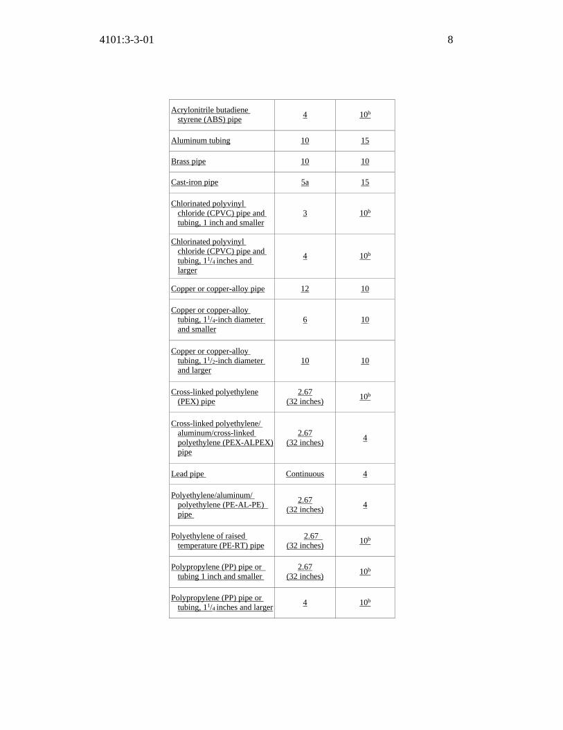
4101:3-3-01 8
Acrylonitrile butadiene styrene (ABS) pipe
4 10b
Aluminum tubing 10 15
Brass pipe 10 10
Cast-iron pipe 5a 15
Chlorinated polyvinyl chloride (CPVC) pipe and tubing, 1 inch and smaller
3 10b
Chlorinated polyvinyl chloride (CPVC) pipe and tubing, 11/4 inches and larger
4 10b
Copper or copper-alloy pipe 12 10
Copper or copper-alloy tubing, 11/4-inch diameter and smaller
6 10
Copper or copper-alloy tubing, 11/2-inch diameter and larger
10 10
Cross-linked polyethylene (PEX) pipe
2.67 (32 inches)
10b
Cross-linked polyethylene/ aluminum/cross-linked polyethylene (PEX-ALPEX) pipe
2.67 (32 inches)
4
Lead pipe Continuous 4
Polyethylene/aluminum/ polyethylene (PE-AL-PE) pipe
2.67 (32 inches)
4
Polyethylene of raised temperature (PE-RT) pipe
2.67 (32 inches)
10b
Polypropylene (PP) pipe or tubing 1 inch and smaller
2.67 (32 inches)
10b
Polypropylene (PP) pipe or tubing, 11/4 inches and larger
4 10b

4101:3-3-01 9
Polyvinyl chloride (PVC) pipe 4 10b
Stainless steel drainage systems
10 10b
Steel pipe 12 15
For SI: 1 inch = 25.4 mm, 1 foot = 304.8 mm. a. The maximum horizontal spacing of cast-iron pipe hangers
shall be increased to 10 feet where 10-foot lengths of pipe are installed.
b. For sizes 2 inches and smaller, a guide shall be installed midway between required vertical supports. Such guides shall prevent pipe movement in a direction perpendicular to the axis of the pipe.
308.6 Sway bracing. Rigid support sway bracing shall be provided at changes in direction greater than 45 degrees (0.79 rad) for pipe sizes 4 inches (102 mm) and larger. 308.7 Anchorage. Anchorage shall be provided to restrain drainage piping from axial movement.
308.7.1 Location. For pipe sizes greater than 4 inches (102 mm), restraints shall be provided for drain pipes at all changes in direction and at all changes in diameter greater than two pipe sizes. Braces, blocks, rodding and other suitable methods as specified by the coupling manufacturer shall be utilized.
308.8 Expansion joint fittings. Expansion joint fittings shall be used only where necessary to provide for expansion and contraction of the pipes. Expansion joint fittings shall be of the typical material suitable for use with the type of piping in which such fittings are installed. 308.9 Parallel water distribution systems. Piping bundles for manifold systems shall be supported in accordance with Table 308.5. Support at changes in direction shall be in accordance with the manufacturer’s instructions. Where hot water piping is bundled, each hot water pipe shall be insulated.
SECTION 309 FLOOD HAZARD RESISTANCE
309.1 General. All buildings and structures which have been determined to require flood resistant construction by the local flood plain administrator, as a participant in the "National Flood Insurance Program", shall be constructed as required by the provisions of section 1612 of the building code for approval

4101:3-3-01 10
under the "Regulations for Floodplain Management and Flood Hazard Identification" of the "National Flood Insurance Program" pursuant to “FEMA 44 CFR Parts 59-77" and the authority's "Flood Damage Prevention Ordinance.". 309.2 Flood hazard. For structures located in flood hazard areas, the following systems and equipment shall be located and installed as required by Section 1612 of the building code.
1. Water service pipes. 2. Deleted. 3. Deleted. 4. Sanitary drainage piping. 5. Storm drainage piping. 6. Deleted. 7. Other plumbing fixtures, faucets, fixture fittings, piping systems and
equipment. 8. Water heaters. 9. Vents and vent systems. Exception: The systems listed in this section are permitted to be located below the elevation required by Section 1612 of the building code for utilities and attendant equipment, provided that the systems are designed and installed to prevent water from entering or accumulating within their components and the systems are constructed to resist hydrostatic and hydrodynamic loads and stresses, including the effects of buoyancy, during the occurrence of flooding up to such elevation.
309.3 Coastal high-hazard areas and coastal A zones. Deleted.
SECTION 310 WASHROOM AND TOILET ROOM REQUIREMENTS
310.1 Light and ventilation. Washrooms and toilet rooms shall be illuminated and ventilated in accordance with the building code and mechanical code. 310.2 Location of fixtures and compartments. The location of plumbing fixtures and the requirements for compartments and partitions shall be in accordance with Section 405.3. 310.3 Interior finish. Interior finish surfaces of toilet rooms shall comply with the building code.

4101:3-3-01 11
310.4 Enforcement. Enforcement of the provisions of this section is the responsibility of the certified building official of the certified municipal, county, or township building department having jurisdiction or the superintendent of the division of industrial compliance.
SECTION 311 TOILET FACILITIES FOR WORKERS
311.1 General. Deleted.
SECTION 312 TESTS AND INSPECTIONS
312.1 Required tests. The owner or owner’s representative shall cause the applicable tests and inspections prescribed in Sections 312.2 through 312.11 to be performed to determine that the work will withstand the prescribed test without leakage and to demonstrate the integrity of the device or assembly. In accordance with OBC Section 108.8, reasonable advanced notice shall be given to the building official when the plumbing work is ready for tests. The building official may require that the tests be conducted in the presence of the building official or certified plumbing inspector. The owner or owner’s representative shall keep records of the tests and inspections and shall submit such records to the building official upon request.
312.1.1 New, altered, extended or repaired systems. New plumbing systems and parts of existing systems that have been altered, extended, or repaired shall be tested as prescribed herein to disclose leaks and defects, except that testing is not required in the following cases:
1. In any case that does not include addition to, replacement, alteration or relocation of any water supply, drainage or vent piping.
2. In any case where plumbing equipment is set up temporarily for exhibition purposes.
312.1.2 Equipment, material, power and labor for tests. Equipment, material, power and labor necessary for testing a plumbing system or part thereof shall be furnished by the owner or the owner’s representative. Required tests shall be conducted by and at the expense of the owner or the owner’s representative.
312.1.3 Test gauges. Gauges used for testing shall be as follows:

4101:3-3-01 12
1. Tests requiring a pressure of 10 pounds per square inch (psi) (69 kPa) or less shall utilize a testing gauge having increments of 0.10 psi (0.69 kPa) or less.
2. Tests requiring a pressure of greater than 10 psi (69 kPa) but less than or equal to 100 psi (689 kPa) shall utilize a testing gauge having increments of 1 psi (6.9 kPa) or less.
3. Tests requiring a pressure of greater than 100 psi (689 kPa) shall utilize a testing gauge having increments of 2 psi (14 kPa) or less.
312.1.4 Test media. All plumbing system piping, fittings, and shower liners shall be tested with water.
Exception: Plumbing system piping and fittings are permitted to be tested as prescribed in Sections 312.2 to 312.8 with air, another compressed gas, vacuum, or other media or method only when the manufacturer of the proposed piping, fittings and solvent cement (if applicable) allows the alternative method of testing. Where this code does not address or prescribe an alternative test method, an alternative test method prescribed by the manufacturer of the piping, fittings, or solvent cement in the published manufacturer’s installation instructions will be acceptable as meeting the requirements of this code.
312.1.5 Reinspection and testing. Where any work or installation does not pass any initial test or inspection, the necessary corrections shall be made to comply with this code.
312.2 Drainage and vent rough-in test. Drainage and vent piping and fittings shall be tested prior to the installation of the plumbing fixtures and prior to the installation of wall and ceiling coverings to verify the integrity of the system in accordance with one of the following methods prescribed in Section 312.2.1, 312.2.2, or 312.2.3:
312.2.1 Drainage and vent rough-in water test. A water test shall be applied to the drainage system either in its entirety or in sections. If applied to the entire system, all openings in the piping shall be tightly closed, except the highest opening, and the system shall be filled with water to the point of overflow. If the system is tested in sections, each opening shall be tightly plugged except the highest openings of the section under test, and each section shall be filled with water, but no section shall be tested with less than a 10-foot (3048 mm) head of water. In testing successive sections, at least the upper 10 feet (3048 mm) of the next preceding section shall be tested so that no joint or pipe in the building, except the uppermost 10 feet (3048 mm) of the system,

4101:3-3-01 13
shall have been submitted to a test of less than a 10-foot (3048 mm) head of water. This pressure shall be held for at least 15 minutes. The system shall then be tight at all points. 312.2.2 Drainage and vent rough-in air test. When permitted by the manufacturer of the piping, fittings, and solvent cement (if part of the plumbing system), an air test shall be made by forcing air into the system until there is a uniform gauge pressure of 5 psi (34.5 kPa) or sufficient to balance a 10-inch (254 mm) column of mercury. This pressure shall be held for a test period of at least 15 minutes. Any adjustments to the test pressure required because of changes in ambient temperature or the seating of gaskets shall be made prior to the beginning of the test period. Testing shall be done with dual pressure relief valves rated for 7.5 psig. 312.2.3 Alternative drainage and vent rough–in test. When permitted by the manufacturer of the piping, fittings, and solvent cement (if part of the plumbing system), an alternative method of testing the drainage and vent system, such as compressed gas or vacuum, may be permitted to meet the drainage and vent rough-in test requirements of this code as long as the test is conducted strictly in accordance with the requirements published in the manufacturer’s installation instructions.
312.3 Not used. 312.4 Drainage and vent final test. After the plumbing fixtures have been set and their traps filled with water, the entire drainage system shall be subjected to one of the following final tests as prescribed by the building official:
312.4.1 Visual and operational final test. All plumbing fixtures shall be operated and a visual inspection of accessible piping and joints shall be performed to determine that there are no visible leaks. 312.4.2 Drainage and vent final test. The final test of the completed drainage and vent systems shall be made, after the fixtures are connected, as follows:
1. Close all stack openings; 2. A manometer tube shall be placed through a trap seal to the system side
and water shall be added to a fixture until an equivalent of at least 1 in. water column (248.8 Pa) is read on the manometer gauge or water-can. Water may be added to a water closet bowl or trap tailpiece extension until the water level is at least one inch higher than the original trap seal;
4101:3-3-01 14
3. Maintain the initial water column for fifteen (15) minutes; 4. The system shall then be separated at a trap seal, AAV, or other means
as directed by the plumbing inspector for verification that the entire system is interconnected.
312.4.3 Alternative drainage and vent final test. Any other testing method equal to the 1 in. water column. Except as provided for in Section 312.4.2, compressed or stored air may not be used unless otherwise permitted by the manufacturer of piping, fittings, and solvent cement (if part of the plumbing system).
312.5 Water supply system test. Upon completion of a section of or the entire water supply system, the system, or portion completed, shall be tested to verify the integrity of the system in accordance with one of the following methods prescribed in Sections 312.5.1 or 312.5.2:
312.5.1 Water supply working pressure test. A water pressure test at not less than the working pressure under which the system is to be used shall be performed to prove the system watertight. This pressure shall be held for at least 15 minutes. The water utilized for tests shall be obtained from a potable source of supply. 312.5.2 Water supply air test. When permitted by the manufacturer of the piping, fittings, and solvent cement (if part of the plumbing system), an air test of not less than 50 psi (344 kPa) shall be performed to prove the system air-tight. This pressure shall be held for at least 15 minutes.
312.6 Gravity sewer test. Deleted. 312.7 Forced sewer test. Deleted. 312.8 Storm drainage system test. Storm drain systems within a building shall be tested in accordance with Section 312.2. 312.9 Shower liner test. Where shower floors and receptors are made water-tight by the application of materials required by Section 417.5.2, the completed liner installation shall be tested. The pipe from the shower drain shall be plugged water tight for the test. The floor and receptor area shall be filled with potable water to a depth of not less than 2 inches (51 mm) measured at the threshold. Where a threshold of at least 2 inches (51 mm) high does not exist, a temporary threshold shall be constructed to retain the test water in the lined floor or receptor area to a
4101:3-3-01 15
level not less than 2 inches (51 mm) deep measured at the threshold. The water shall be retained for a test period of not less than 15 minutes, and there shall not be evidence of leakage.
Exception: The shower liner test is not required for one-, two-, or three-family dwellings unless required by the shower liner manufacturer’s installation instructions.
312.10 Inspection and testing of isolation backflow prevention devices required by this code. Inspection and testing of isolation backflow prevention devices shall comply with Sections 312.10.1 and 312.10.2. Inspection and testing requirements for containment backflow prevention devices required by the water supplier shall be in accordance with rule 3745-95-06 of the Administrative Code and enforced by the water supplier.
312.10.1 Inspections. The owner shall maintain all backflow prevention assemblies and air gaps in good working condition. Annual inspections shall be made of all backflow prevention assemblies and air gaps to determine whether they are operable. 312.10.2 Testing. Reduced pressure principle, double check, pressure vacuum breaker, reduced pressure detector fire protection, double check detector fire protection, and spill-resistant vacuum breaker backflow prevention assemblies and hose connection backflow preventers shall be tested at the time of installation, immediately after repairs or relocation and at least annually. The testing procedure shall be performed in accordance with one of the following standards: ASSE 5013 for reduced pressure principle and reduced pressure principle fire protection backflow prevention assemblies, ASSE 5015 for double check and double check fire protection backflow prevention assemblies, ASSE 5020 for pressure vacuum breaker assemblies, ASSE 5047 for reduced pressure detector fire protection backflow prevention assemblies, ASSE 5048 for double check detector fire protection backflow prevention assemblies, ASSE 5052 for hose connection backflow preventers, ASSE 5056 for spill resistant vacuum breaker assemblies, CSA B64.10 or CSA B64.10.1.
312.11 Operational testing of low pressure cut-off device, low suction throttling valves, and variable speed suction limiting controls. Although enforcement of this section is outside the scope of the plumbing code, it is important for owners to note that rule 3745-95-07 of the Administrative Code requires that the owner certify to the supplier of water that their low pressure cut-off devices, low suction throttling valves, and variable speed suction limiting controls are maintained in

4101:3-3-01 16
proper working order. Enforcement of this requirement and the referenced rule is the responsibility of the water supplier. See Section 606.5.5 of this code for additional information. 312.12 Inspections. No part of any plumbing or drainage system shall be covered until it has been inspected, tested, and approved, except as provided in this section. Failure of the inspector to inspect the work within four days, exclusive of Saturdays, Sundays, and legal holidays, after the work is ready for inspection, allows the work to proceed.
SECTION 313 EQUIPMENT EFFICIENCIES
313.1 General. Equipment efficiencies shall be in accordance with the applicable standard referenced in Chapter 13 of the building code or Chapter 11 of the “Residential Code of Ohio”.
SECTION 314 CONDENSATE DISPOSAL
314.1 Fuel-burning appliances. Liquid combustion byproducts of condensing appliances shall be collected and discharged to an approved plumbing fixture or disposal area in accordance with the manufacturer’s instructions. Condensate piping shall be of approved corrosion-resistant material and shall not be smaller than the drain connection on the appliance. Such piping shall maintain a horizontal slope in the direction of discharge of not less than one-eighth unit vertical in 12 units horizontal (1-percent slope). 314.2 Evaporators and cooling coils. Condensate drain systems shall be provided for equipment and appliances containing evaporators or cooling coils. Condensate drain systems shall be designed, constructed and installed in accordance with Sections 314.2.1 through 314.2.5.
314.2.1 Condensate disposal. Condensate from all cooling coils and evaporators shall be conveyed from the drain pan outlet to an approved place of disposal. Such piping shall maintain a horizontal slope in the direction of discharge of not less than one-eighth unit vertical in 12 units horizontal (1-percent slope). Condensate shall not discharge into a street, alley or other areas so as to cause a nuisance.

4101:3-3-01 17
314.2.2 Drain pipe materials and sizes. Components of the condensate disposal system shall be cast iron, galvanized steel, copper, cross-linked polyethylene, polyethylene, ABS, CPVC or PVC or polypropylene pipe or tubing. All components shall be selected for the pressure and temperature rating of the installation. Joints and connections shall be made in accordance with the applicable provisions of Chapter 7 relative to the material type. Condensate waste and drain line size shall be not less than 3/4-inch (19.1 mm) internal diameter and shall not decrease in size from the drain pan connection to the place of condensate disposal. Where the drain pipes from more than one unit are manifolded together for condensate drainage, the pipe or tubing shall be sized in accordance with Table 314.2.2.
TABLE 314.2.2
CONDENSATE DRAIN SIZING
EQUIPMENT CAPACITY
MINIMUM CONDENSATE
PIPE DIAMETER (inch)
Up to 20 tons of refrigeration 3/4
inch
Over 20 tons to 40 tons of refrigeration 1 inch
Over 40 tons to 90 tons of refrigeration 11/4 inch
Over 90 tons to 125 tons of refrigeration 11/2 inch
Over 125 tons to 250 tons of refrigeration 2 inch
For SI: 1 inch = 25.4 mm, 1 ton of capacity = 3.517 kW.
314.2.3 Auxiliary and secondary drain systems. In addition to the requirements of Section 314.2.1, where damage to any building components could occur as a result of overflow from the equipment primary condensate removal system, one of the following auxiliary protection methods shall be provided for each cooling coil or fuel-fired appliance that produces condensate:
1. An auxiliary drain pan with a separate drain shall be provided under the coils on which condensation will occur. The auxiliary pan drain shall discharge to a conspicuous point of disposal to alert occupants in the event of a stoppage of the primary drain. The pan shall have a depth of not less than 11/2 inches (38 mm), shall be not less than 3 inches (76 mm) larger than the unit or the coil dimensions in width and length and shall be constructed of corrosion-resistant material. Galvanized sheet metal pans shall have a thickness of not less than 0.0236-inch (0.6010 mm) (No. 24 gage) galvanized sheet metal.

4101:3-3-01 18
Nonmetallic pans shall have a thickness of not less than 0.0625 inch (1.6 mm).
2. A separate overflow drain line shall be connected to the drain pan provided with the equipment. Such overflow drain shall discharge to a conspicuous point of disposal to alert occupants in the event of a stoppage of the primary drain. The overflow drain line shall connect to the drain pan at a higher level than the primary drain connection.
3. An auxiliary drain pan without a separate drain line shall be provided under the coils on which condensate will occur. Such pan shall be equipped with a water-level detection device conforming to UL 508 that will shut off the equipment served prior to overflow of the pan. The auxiliary drain pan shall be constructed in accordance with Item 1 of this section.
4. A water-level detection device conforming to UL508 shall be provided that will shut off the equipment served in the event that the primary drain is blocked. The device shall be installed in the primary drain line, the overflow drain line or in the equipment-supplied drain pan, located at a point higher than the primary drain line connection and below the overflow rim of such pan.
Exception: Fuel-fired appliances that automatically shut down operation in the event of a stoppage in the condensate drainage system.
314.2.3.1 Water-level monitoring devices. On down-flow units and all other coils that do not have a secondary drain or provisions to install a secondary or auxiliary drain pan, a water-level monitoring device shall be installed inside the primary drain pan. This device shall shut off the equipment served in the event that the primary drain becomes restricted. Devices installed in the drain line shall not be permitted. 314.2.3.2 Appliance, equipment and insulation in pans. Where appliances, equipment or insulation are subject to water damage when auxiliary drain pans fill such portions of the appliances, equipment and insulation shall be installed above the flood level rim of the pan. Supports located inside of the pan to support the appliance or equipment shall be water resistant and approved.
314.2.4 Traps. Condensate drains shall be trapped as required by the equipment or appliance manufacturer.
314.2.4.1 Ductless mini-split system traps. Ductless mini-split

4101:3-3-01 19
equipment that produces condensation shall be provided with an in-line check valve located in the drain line or a trap.
314.2.5 Cleanouts. Condensate drain lines shall be configured to permit the clearing of blockages and performance of maintenance without requiring the drain line to be cut.
314.3 Enforcement. Enforcement of the provisions of this section is the responsibility of the certified building official of the certified municipal, county, or township building department having jurisdiction or the superintendent of the division of industrial compliance.
SECTION 315 PENETRATIONS
315.1 Sealing of annular spaces. The annular space between the outside of a pipe and the inside of a pipe sleeve or between the outside of a pipe and an opening in a building envelope wall, floor, or ceiling assembly penetrated by a pipe shall be sealed in an approved manner with caulking material, foam sealant or closed with a gasketing system. The caulking material, foam sealant or gasketing system shall be designed for the conditions at the penetration location and shall be compatible with the pipe, sleeve and building materials in contact with the sealing materials. Annular spaces created by pipes penetrating fire-resistance-rated assemblies or membranes of such assemblies shall be sealed or closed in accordance with Section 714 of the building code.
SECTION 316 ALTERNATIVE ENGINEERED DESIGN
316.1 Alternative engineered design. See Section 106.5 of the building code.
SECTION 317 WELDING AND BRAZING
317.1 Scope. This section, consistent with section 4104.44 of the Revised Code, governs the requirements for welding and brazing of metallic building services (including medical gas) piping systems referenced by this code. 317.2 Procedure specification. Each manufacturer or contractor of metallic building services piping systems is responsible for the welding and brazing done by his company or organization and shall specify and certify, in writing, a

4101:3-3-01 20
welding or brazing procedure that provides specific direction to the welder or brazer and complies with section IX of the ASME Boiler and Pressure Vessel Code. 317.3 Procedure qualification records. Each manufacturer or contractor is responsible for getting each procedure described in section 317.2 qualified by an independent testing laboratory that has, on staff, a welding inspector certified by the “American Welding Society (AWS).” Qualification testing determines that the specified joint construction is capable of providing the required properties for its intended application. The procedure qualification record (PQR) documents what occurred during the welding or brazing of the test coupon, identifies all essential variables, and documents the test results. The manufacturer or contractor shall certify on the record that the tests were conducted in accordance with section IX of the ASME Boiler and Pressure Vessel Code. 317.4 Performance qualification testing. Each welder and brazer that performs a welding or brazing procedure as described in section 317.2 shall be tested and qualified on that procedure as required in section IX of the ASME Boiler and Pressure Vessel Code. The manufacturer or contractor, shall certify on the performance qualification record that the welder or brazer prepared and welded or brazed the test coupons in accordance with section IX and that the test coupons were tested by an independent testing laboratory that has, on staff, a welding inspector certified by the “American Welding Society (AWS).” 317.5 Submission of welding and brazing forms to the division of industrial compliance (DIC). Each manufacturer or contractor of metallic building services piping systems referenced by this code who causes welding or brazing to be performed shall file with the superintendent of the division of industrial compliance in the department of commerce, or the superintendent’s designee, certified copies of the welding and brazing procedure specifications, the procedure qualification records, and the welder and brazer performance qualifications of the welders and brazers used in the proposed construction of a new or altered piping system. The required documentation shall be submitted in accordance with rules adopted by the superintendent.

Replaces: 4101:3-3-01
Effective: 11/01/2017
Five Year Review (FYR) Dates: 11/01/2022
CERTIFIED ELECTRONICALLY
Certification
05/26/2017
Date
Promulgated Under: 119.03Statutory Authority: 3781.10(A)Rule Amplifies: 3781.10, 3781.11, 3791.04, 4104.44Prior Effective Dates: 4/15/74, 7/1/78, 12/1/85, 7/5/93, 2/1/96, 1/1/97,
3/1/98, 7/1/98, 1/1/02, 8/15/03, 1/1/04, 3/1/05, 9/6/05,7/1/07, 11/1/11, 7/1/14, 1/1/16, 10/10/16
4101:3-3-01 21

4101:3-4-01 Fixtures, faucets and fixture fittings. [Comment: When a reference is made within this rule to a federal statutory provision, an industry consensus standard, or any other technical publication, the specific date and title of the publication as well as the name and address of the promulgating agency are listed in rule 4101:3-15-01 of the Administrative Code. The application of the referenced standards shall be limited and as prescribed in section 102.5 of rule 4101:1-1-01 of the Administrative Code.]
SECTION 401
GENERAL 401.1 Scope. This chapter shall govern the materials, design and installation of plumbing fixtures, faucets and fixture fittings in accordance with the type of occupancy, and shall provide for the minimum number of fixtures for various types of occupancies. 401.2 Prohibited fixtures and connections. Water closets having a concealed trap seal or an unventilated space or having walls that are not thoroughly washed at each discharge in accordance with ASME A112.19.2/CSA B45.1 shall be prohibited. Any water closet that permits siphonage of the contents of the bowl back into the tank shall be prohibited. Trough urinals shall be prohibited. 401.3 Water conservation. The maximum water flow rates and flush volume for plumbing fixtures and fixture fittings shall comply with Section 604.4.
SECTION 402 FIXTURE MATERIALS
402.1 Quality of fixtures. Plumbing fixtures shall be constructed of approved materials, with smooth, impervious surfaces, free from defects and concealed fouling surfaces, and shall conform to standards cited in this code. All porcelain enameled surfaces on plumbing fixtures shall be acid resistant. 402.2 Materials for specialty fixtures. Materials for specialty fixtures not otherwise covered in this code shall be of stainless steel, soapstone, chemical stoneware or plastic, or shall be lined with lead, copper-base alloy, nickel-copper alloy, corrosion-resistant steel or other material especially suited to the application for which the fixture is intended. 402.3 Sheet copper. Sheet copper for general applications shall conform to
ACTION: Final DATE: 05/26/2017 2:37 PM
RB p(170947) pa(315228) d(672529) ra(523781) print date: 05/31/2017 2:41 PM
4101:3-4-01 2
ASTM B 152 and shall not weigh less than 12 ounces per square foot (3.7 kg/m2). 402.4 Sheet lead. Sheet lead for pans shall not weigh less than 4 pounds per square foot (19.5 kg/m2) and shall be coated with an asphalt paint or other approved coating.
SECTION 403 MINIMUM PLUMBING FACILITIES
403.1 Minimum number of fixtures. Plumbing fixtures shall be provided in the minimum number as shown in Table 403.1, based on the actual use of the building or space. Uses not shown in Table 403.1 shall be considered individually by the building official. The number of occupants shall be determined by the building code. When the actual occupant load will be significantly different than that determined by section 1004 of the building code, the building official may establish an alternate basis for determining the occupant load. This alternate basis shall be included in the special stipulations and conditions section of the certificate of occupancy issued for that structure pursuant to section 110 of the building code. For accessibility requirements, see “Chapter 11, Accessibility” of the building code.
Exception: Facilities are not required in buildings less than 100 square feet in area if fixtures are available within 500 feet of the building.
TABLE 403.1 MINIMUM NUMBER OF REQUIRED PLUMBING FIXTURESa
(See Sections 403.1.1 and 403.2)
NO. CLASSIFICATION OCCUPANCY DESCRIPTION
WATER CLOSETS (URINALS: See footnote g)
LAVATORIES BATHTUBS/ SHOWERS
DRINKING FOUNTAINS
(See Section 410 for exceptions)
OTHER MALE FEMALE MALE FEMALE
1
Assembly
A-1d
Theaters and other buildings for the performing arts and motion pictures
1 per 125 1 per 65 1 per 200 — 1 per 500 1 service sink
A-2d
Nightclubs, bars, taverns, dance halls and buildings for similar purposes
1 per 40 1 per 40 1 per 75 — 1 per 500 1 service sink
Casino gaming areas
1:1-100 3:1-50 1:1-200 - - 1 service sink
- 4:51-100 2:201-400

4101:3-4-01 3
2:101-200 6:101-200 3:401-750 3:201-400 8:201-400
Over 750, add one fixture for each additional
500 persons
Over 400, add one fixture each additional 250 males, and one for
each 150 females. Restaurants, banquet halls and food courts
1 per 75 1 per 75 1 per 200 — 1 per 500 1 service sink
A-3d
Auditoriums without permanent seating, art galleries, exhibition halls, museums, lecture halls, libraries, arcades and gymnasiums
1 per 125 1 per 65 1 per 200 — 1 per 500 1 service sink
Passenger terminals and transportation facilities
1 per 500 1 per 500 1 per 750 — 1 per 1,000 1 service sink
Places of worship and other religious services.
1 per 150 1 per 75 1 per 200 — 1 per 1,000 1 service sink
A-4
Coliseums, arenas, skating rinks, pools and tennis courts for indoor sporting events and activities
1 per 75 for the
first 1,500 and 1 per 120 for
the remainder exceeding
1,500
1 per 40 for the
first 1,520 and 1 per 60 for the remainder exceeding
1,520
1 per 200
1 per 150
— 1 per 1,000 1 service sink
A-5
Stadiums, amusement parks, bleachers and grandstands for outdoor sporting events and activities
1 per 75 for the
first 1,500 and 1 per 120 for
the remainder exceeding
1,500
1 per 40 for the
first 1,520 and 1 per 60 for the remainder exceeding
1,520
1 per 200
1 per 150
— 1 per 1,000 1 service sink
2 Business B
Buildings for the transaction of business, professional services, other services involving merchandise, office buildings, banks, light industrial and similar uses
1 per 50 1 per 80 — 1 per 100 1 service sinke
3 Educational E Educational facilities 1 per 50 1 per 50 — 1 per 100 1 service sink

4101:3-4-01 4
4 Factory and industrial
F-1 and F-2
Structures in which occupants are engaged in work fabricating, assembly or processing of products or materials
1 per 100 1 per 100 (see
Section 411)
1 per 400 1 service sink
5 Institutional
I-1 Residential care
1 per 10 1 per 10 1 per 8 1 per 100 1 service sink
I-2
Hospitals, ambulatory nursing home care recipientb
1 per roomc 1 per roomc 1 per 15 1 per 100 1 service sink
per floor
Employees, other than residential careb
1 per 25 1 per 35 — 1 per 100 —
Visitors, other than residential care
1 per 75 1 per 100 — 1 per 500 —
I-3
Prisonsb 1 per cell 1 per cell 1 per 15 1 per 100 1 service sink
Reformitories, detention centers, and correctional centersb
1 per 15 1 per 15 1 per 15 1 per 100 1 service sink
Employeesb 1 per 25 1 per 35 — 1 per 100 —
I-4 Adult day care and child care 1 per 15 1 per 15 1 1 per 100 1 service sink
6 Mercantilef M
Retail stores, service stations, shops, salesrooms, markets and shopping centers
1 per 500 1 per 750 — 1 per 1,000 1 service sinke
7 Residential
R-1 Hotels, motels, boarding houses (transient)
1 per sleeping unit 1 per sleeping
unit
1 per sleeping
unit — 1 service sink
R-2
Dormitories, fraternities, sororities and boarding houses (not transient)
1 per 10 1 per 10 1 per 8 1 per 100 1 service sink
R-2 Apartment house 1 per dwelling unit 1 per dwelling
unit
1 per dwelling
unit —
1 kitchen sink per dwelling
unit; 1 automatic
clothes washer connection per
20 dwelling units
R-3
One-, Two-, and Three-family dwellings,
Multiple single-family
dwellings, and lodging houses
with five or fewer
1 per dwelling unit 1 per dwelling
unit
1 per dwelling
unit —
1 kitchen sink per dwelling
unit; 1 automatic
clothes washer connection per dwelling unit
4101:3-4-01 5
guestrooms
R-3
Congregate living facilities with 16 or fewer persons and other R-3 occupancies
1 per 10 1 per 10 1 per 8 1 per 100 1 service sink
R-4
Congregate care/residential care/assisted living facilities
1 per 10 1 per 10 1 per 8 1 per 100 1 service sink
8 Storage S-1 S-2
Structures for the storage of goods, warehouses, storehouse and freight depots. Low and Moderate Hazard.
1 per 100 1 per 100 See
Section 411
1 per 1,000 1 service sink
a. The fixtures shown are based on one fixture being the minimum required for the number of persons indicated or any fraction of the number of persons indicated. The number of occupants shall be determined by the building code.
b. Toilet facilities for employees shall be separate from facilities for inmates or care recipients. c. A single-occupant toilet room with one water closet and one lavatory serving not more than two adjacent patient sleeping units
shall be permitted, provided that each patient sleeping unit has direct access to the toilet room and provisions for privacy for the toilet room user are provided.
d. The occupant load for seasonal outdoor seating and entertainment areas shall be included when determining the minimum number of facilities required.
e. For business and mercantile occupancies with an occupant load of 15 or fewer, service sinks shall not be required. f. Mercantile occupancies are not required to provide customer facilities when the occupant load is 50 or less. g. In each bathroom or toilet room, urinals shall not be substituted for more than 67 percent of the required water closets in
assembly and educational occupancies. Urinals shall not be substituted for more than 50 percent of the required water closets in all other occupancies.

4101:3-4-01 6
403.1.1 Fixture calculations. To determine the occupant load of each sex, the total occupant load shall be divided in half. To determine the required number of fixtures, the fixture ratio or ratios for each fixture type shall be applied to the occupant load of each sex in accordance with Table 403.1. Fractional numbers resulting from applying the fixture ratios of Table 403.1 shall be rounded up to the next whole number. For calculations involving multiple occupancies, such fractional numbers for each occupancy shall first be summed and then rounded up to the next whole number.
Exception: The total occupant load shall not be required to be divided in half where approved statistical data indicates a distribution of the sexes of other than 50 percent of each sex.
403.1.2 Single-user toilet facility and bathing room fixtures. The plumbing fixtures located in single-user toilet facilities and bathing rooms, including family or assisted-use toilet and bathing rooms that are required by Section 1109.2.1 of the building code shall contribute towards the total number of required plumbing fixtures for a building or tenant space. Single-user toilet facilities and bathing rooms, and family or assisted-use toilet and bathing rooms shall be identified for use by either sex.
403.2 Separate facilities. Where plumbing fixtures are required, separate facilities shall be provided for each sex.
Exceptions: 1. Separate facilities shall not be required for dwelling units and sleeping
units. 2. Separate facilities shall not be required in structures or tenant spaces with
a total occupant load, including both employees and customers, of 15 or fewer.
3. Separate facilities shall not be required in mercantile occupancies in which the maximum occupant load is 100 or fewer.
4. Separate facilities shall not be required in business occupancies in which the maximum occupant load is 25 or fewer.
403.2.1 Family or assisted-use toilet facilities serving as separate facilities. Where a building or tenant space requires a separate toilet facility for each sex and each toilet facility is required to have only one water closet, two family or assisted-use toilet facilities shall be permitted to serve as the required separate facilities. Family or assisted use toilet facilities shall not be required to be identified for exclusive use by either sex as required by Section 403.4.
4101:3-4-01 7
403.3 Required public toilet facilities. Customers, patrons and visitors shall be provided with public toilet facilities in structures and tenant spaces intended for public utilization. The number of plumbing fixtures located within the required toilet facilities shall be provided in accordance with Section 403 for all users. Employees shall be provided with toilet facilities in all occupancies. Employee toilet facilities shall be either separate or combined employee and public toilet facilities.
Exception: Public toilet facilities shall not be required in: 1. Open or enclosed parking garages. 2. Structures and tenant spaces intended for quick transactions, including
takeout, pickup and dropoff, having a public access area less than or equal to 300 square feet (28 m2).
403.3.1 Access. The route to the public toilet facilities required by Section 403.3 shall not pass through kitchens, storage rooms, closets or similar spaces not available to the public. Access to the required facilities shall be from within the building or from the exterior of the building. Routes shall comply with the accessibility requirements of the building code. The public shall have access to the required toilet facilities at all times that the building is occupied. The building owner is permitted to control access to the toilet facilities. Where such access is controlled, a sign shall be posted indicating how access is to be obtained. 403.3.2 Prohibited toilet room location. Toilet rooms shall not open directly into a room used for the preparation of food for service to the public. 403.3.3 Location of toilet facilities in occupancies other than malls. In occupancies other than covered and open mall buildings, the required public and employee toilet facilities shall be located not more than one story above or below the space required to be provided with toilet facilities, and the path of travel to such facilities shall not exceed a distance of 500 feet (152 m).
Exception: The location and maximum distances of travel to required employee facilities in factory and industrial occupancies are permitted to exceed that required by this section, provided that the location and maximum distance of travel are approved.
403.3.4 Location of toilet facilities in malls. In covered and open mall buildings, the required public and employee toilet facilities shall be located not more than one story above or below the space required to be provided with toilet facilities, and the path of travel to such facilities shall not exceed a distance of 300 feet (91 m). In mall buildings, the required facilities shall be

4101:3-4-01 8
based on total square footage within a covered mall building or within the perimeter line of an open mall building, and facilities shall be installed in each individual store or in a central toilet area located in accordance with this section. The maximum distance of travel to central toilet facilities in mall buildings shall be measured from the main entrance of any store or tenant space. In mall buildings, where employees’ toilet facilities are not provided in the individual store, the maximum distance of travel shall be measured from the employees’ work area of the store or tenant space. 403.3.5 Pay facilities. Where pay facilities are installed, such facilities shall be in excess of the required minimum facilities. Required facilities shall be free of charge. 403.3.6 Door locking. Where a toilet room is provided for the use of multiple occupants, the egress door for the room shall not be lockable from the inside of the room. This section does not apply to family or assisted-use toilet rooms.
403.4 Signage. Required public facilities shall be provided with signs that designate the sex, as required by Section 403.2. Signs shall be readily visible and located near the entrance to each toilet facility. Signs for accessible toilet facilities shall comply with Section 1111 of the building code.
403.4.1 Directional signage. Deleted.
403.5 Drinking fountain location. Drinking fountains shall not be required to be located in individual tenant spaces provided that public drinking fountains are located within a distance of travel of 500 feet (152 m) of the most remote location in the tenant space and not more than one story above or below the tenant space. Where the tenant space is in a covered or open mall, such distance shall not exceed 300 feet (91 m). Drinking fountains shall be located on an accessible route. 403.6 Enforcement. This section is identical to Section 2902 of the building code. It is provided in this code for reference only. Enforcement of the provisions of Section 2902 of the building code and this section is the responsibility of the certified building official of the certified municipal, county, or township building department having jurisdiction or the superintendent of the division of industrial compliance.
SECTION 404

4101:3-4-01 9
ACCESSIBLE PLUMBING FACILITIES 404.1 Where required. Accessible plumbing facilities and fixtures shall be provided in accordance with the building code. The provisions of “Chapter 11, Accessibility” of the building code shall control the design and construction of facilities for accessibility to physically disabled persons. 404.2 Accessible fixture requirements. Accessible plumbing fixtures shall be installed with the clearances, heights, spacings and arrangements in accordance with ICC A117.1 and chapter 11 of the building code. 404.3 Exposed pipes and surfaces. Water supply and drain pipes under accessible lavatories and sinks shall be covered or otherwise configured to protect against contact. Pipe coverings shall comply with ASME A112.18.9. 404.4 Enforcement. Enforcement of the provisions of this section is the responsibility of the certified building official of the certified municipal, county, or township building department having jurisdiction or the superintendent of the division of industrial compliance.
SECTION 405 INSTALLATION OF FIXTURES
405.1 Water supply protection. The supply lines and fittings for every plumbing fixture shall be installed so as to prevent backflow. 405.2 Access for cleaning. Plumbing fixtures shall be installed so as to afford easy access for cleaning both the fixture and the area around the fixture. 405.3 Setting. Fixtures shall be set level and in proper alignment with reference to adjacent walls.
405.3.1 Water closets, urinals, lavatories and bidets. A water closet, urinal, lavatory or bidet shall not be set closer than 15 inches (381 mm) from its center to any side wall, partition, vanity or other obstruction, or closer than 30 inches (762 mm) center to center between adjacent fixtures. There shall be not less than a 21-inch (533 mm) clearance in front of the water closet, urinal, lavatory or bidet to any wall, fixture or door. Water closet compartments shall be not less than 30 inches (762 mm) in width and not less than 60 inches (1524 mm) in depth for floor-mounted water closets and not less than 30 inches (762 mm) in width and 56 inches (1422 mm) in depth for wall-hung

4101:3-4-01 10
water closets. See Chapter 11 of the building code for the minimum required dimensions for accessible fixtures. 405.3.2 Public lavatories. In employee and public toilet rooms, the required lavatory shall be located in the same room as the required water closet. 405.3.3 Location of fixtures and piping. Piping, fixtures or equipment shall not be located in such a manner as to interfere with the normal operation of windows, doors or other means of egress openings. 405.3.4 Water closet compartment. Each water closet utilized by the public or employees shall occupy a separate compartment with walls or partitions and a door enclosing the fixtures to ensure privacy.
Exceptions: 1. Water closet compartments shall not be required in a single-occupant
toilet room with a lockable door. 2. Toilet rooms located in child day care facilities and containing two or
more water closets shall be permitted to have one water closet without an enclosing compartment.
3. This provision is not applicable to toilet areas located within Group I-3 housing areas.
405.3.5 Urinal partitions. Each urinal utilized by the public or employees shall occupy a separate area with walls or partitions to provide privacy. The walls or partitions shall begin at a height not greater than 12 inches (305 mm) from and extend not less than 60 inches (1524 mm) above the finished floor surface. The walls or partitions shall extend from the wall surface at each side of the urinal not less than 18 inches (457 mm) or to a point not less than 6 inches (152 mm) beyond the outermost front lip of the urinal measured from the finished back wall surface, whichever is greater.
Exceptions: 1. Urinal partitions shall not be required in a single occupant or
family/assisted-use toilet room with a lockable door. 2. Toilet rooms located in child day care facilities and containing two or
more urinals shall be permitted to have one urinal without partitions.
405.4 Floor and wall drainage connections. Connections between the drain and floor outlet plumbing fixtures shall be made with a floor flange or a waste connector and sealing gasket. The waste connector and sealing gasket joint shall comply with the joint tightness test of ASME A112.4.3 and shall be installed in

4101:3-4-01 11
accordance with the manufacturer’s instructions. The flange shall be attached to the drain and anchored to the structure. Connections between the drain and wall-hung water closets shall be made with an approved extension nipple or horn adaptor. The water closet shall be bolted to the hanger with corrosion-resistant bolts or screws. Joints shall be sealed with an approved elastomeric gasket, flange-to-fixture connection complying with ASME A112.4.3 or an approved setting compound.
405.4.1 Floor flanges. Floor flanges for water closets or similar fixtures shall be not less than 0.125 inch (3.2 mm) thick for brass, 0.25 inch (6.4 mm) thick for plastic and 0.25 inch (6.4 mm) thick and not less than a 2-inch (51 mm) caulking depth for cast iron or galvanized malleable iron. Closet screws and bolts shall be of brass. Flanges shall be secured to the building structure with corrosion-resistant screws or bolts. 405.4.2 Securing floor outlet fixtures. Floor outlet fixtures shall be secured to the floor or floor flanges by screws or bolts of corrosion-resistant material.
405.4.3 Securing wall-hung water closet bowls. Wall-hung water closet bowls shall be supported by a concealed metal carrier that is attached to the building structural members so that strain is not transmitted to the closet connector or any other part of the plumbing system. The carrier shall conform to ASME A112.6.1M or ASME A112.6.2.
405.5 Water-tight joints. Joints formed where fixtures come in contact with walls or floors shall be sealed. 405.6 Plumbing in mental health centers. Deleted. 405.7 Design of overflows. Where any fixture is provided with an overflow, the waste shall be designed and installed so that standing water in the fixture will not rise in the overflow when the stopper is closed, and no water will remain in the overflow when the fixture is empty.
405.7.1 Connection of overflows. The overflow from any fixture shall discharge into the drainage system on the inlet or fixture side of the trap.
Exception: The overflow from a flush tank serving a water closet or urinal shall discharge into the fixture served.
405.8 Slip joint connections. Slip joints shall be made with an approved elastomeric gasket and shall only be installed on the trap outlet, trap inlet and

4101:3-4-01 12
within the trap seal. Fixtures with concealed slip-joint connections shall be provided with an access panel or utility space not less than 12 inches (305 mm) in its smallest dimension or other approved arrangement so as to provide access to the slip joint connections for inspection and repair. 405.9 Design and installation of plumbing fixtures. Integral fixture fitting mounting surfaces on manufactured plumbing fixtures or plumbing fixtures constructed on site shall meet the design requirements of ASME A112.19.2/CSA B45.1 or ASME A112.19.3/CSA B45.4.
SECTION 406 AUTOMATIC CLOTHES WASHERS
406.1 Water connection. The water supply to an automatic clothes washer shall be protected against backflow by an air gap that is integral with the machine or a backflow preventer shall be installed in accordance with Section 608. Air gaps shall comply with ASME A112.1.2 or A112.1.3. 406.2 Waste connection. The waste from an automatic clothes washer shall discharge through an air break into a standpipe in accordance with Section 802.4 or into a laundry sink. The trap and fixture drain for an automatic clothes washer standpipe shall be not less than 2 inches (51 mm) in diameter. The fixture drain for the standpipe serving an automatic clothes washer shall connect to a 3-inch (76 mm) or larger diameter fixture branch or stack. Automatic clothes washers that discharge by gravity shall be permitted to drain to a waste receptor or an approved trench drain.
SECTION 407 BATHTUBS
407.1 Approval. Bathtubs shall conform to ASME A112.19.1/ CSA B45.2, ASME A112.19.2/CSA B45.1, ASME A112.19.3/ CSA B45.4 or CSA B45.5/IAPMO Z124. 407.2 Bathtub waste outlets and overflows. Bathtubs shall be equipped with a waste outlet and an overflow outlet. The outlets shall be connected to waste tubing or piping not less than 11/2 inches (38 mm) in diameter. The waste outlet shall be equipped with a water-tight stopper. 407.3 Glazing. Windows and doors within a bathtub enclosure shall conform to the safety glazing requirements of the building code.

4101:3-4-01 13
407.4 Bathtub enclosure. Doors in a bathtub enclosure shall conform to ASME A112.19.15.
SECTION 408 BIDETS
408.1 Approval. Bidets shall conform to ASME A112.19.2/ CSA B45.1. 408.2 Water connection. The water supply to a bidet shall be protected against backflow by an air gap or backflow preventer in accordance with Section 608.13.1, 608.13.2, 608.13.3, 608.13.5, 608.13.6 or 608.13.8. 408.3 Bidet water temperature. The discharge water temperature from a bidet fitting shall be limited to a maximum temperature of 110°F (43°C) by a water temperature limiting device conforming to ASSE 1070 or CSA B125.3.
SECTION 409 DISHWASHING MACHINES
409.1 Approval. Commercial dishwashing machines shall conform to ASSE 1004 and NSF 3. 409.2 Water connection. The water supply to a dishwashing machine shall be protected against backflow by an air gap that is integral with the machine or a backflow preventer shall be installed in accordance with Section 608. Air gaps shall comply with ASME A112.1.2 or A112.1.3. 409.3 Waste connection. The waste connection of a dishwashing machine shall comply with Section 802.1.6 or 802.1.7, as applicable.
SECTION 410 DRINKING FOUNTAINS
410.1 Approval. Drinking fountains shall conform to ASME A112.19.1/CSA B45.2 or ASME A112.19.2/CSA B45.1 and water coolers shall conform to AHRI 1010. Drinking fountains and water coolers shall conform to NSF 61, Section 9. Electrically operated, refrigerated drinking water coolers shall be listed and labeled in accordance with UL 399.
4101:3-4-01 14
410.2 Small occupancies. Drinking fountains shall not be required for an occupant load of 15 or fewer. 410.3 Provide high and low drinking fountains. Where drinking fountains are required, not fewer than two drinking fountains shall be provided. One drinking fountain shall comply with the requirements for people who use a wheelchair and one drinking fountain shall comply with the requirements for standing persons.
Exception: A single drinking fountain with two separate spouts that complies with the requirements for people who use a wheelchair and standing persons shall be permitted to be substituted for two separate drinking fountains.
410.4 Substitution. Where restaurants provide drinking water in a container free of charge, drinking fountains shall not be required in those restaurants. In other occupancies, where water dispensers are provided, drinking fountains shall not be required. 410.5 Prohibited location. Drinking fountains, water coolers and water dispensers shall not be installed in public toilet facilities.
SECTION 411 EMERGENCY SHOWERS AND EYEWASH STATIONS
411.1 Approval. Emergency showers and eyewash stations shall conform to ISEA Z358.1. 411.2 Waste connection. Waste connections shall not be required for emergency showers and eyewash stations.
SECTION 412 FLOOR AND TRENCH DRAINS
412.1 Approval. Floor drains shall conform to ASME A112.3.1, ASME A112.6.3 or CSA B79. Trench drains shall comply with ASME A112.6.3. 412.2 Floor drains. Floor drains shall have removable strainers. The floor drain shall be constructed so that the drain is capable of being cleaned. Access shall be provided to the drain inlet. Ready access shall be provided to floor drains.
Exception: Floor drains serving refrigerated display cases shall be provided with access.

4101:3-4-01 15
412.3 Size of floor drains. Floor drains shall have a drain outlet not less than 2 inches (51 mm) in diameter. 412.4 Public laundries and central washing facilities. In public coin-operated laundries and in the central washing facilities of multiple-family dwellings, the rooms containing automatic clothes washers shall be provided with floor drains located to readily drain the entire floor area. Such drains shall have an outlet of not less than 3 inches (76 mm) in diameter.
SECTION 413 FOOD WASTE DISPOSER UNITS
413.1 Approval. Domestic food waste disposers shall conform to ASSE 1008 and shall be listed and labeled in accordance with UL 430. Food waste disposers shall not increase the drainage fixture unit load on the sanitary drainage system. 413.2 Domestic food waste disposer waste outlets. Domestic food waste disposers shall be connected to a drain of not less than 11/2 inches (38 mm) in diameter. 413.3 Commercial food waste disposer waste outlets. Commercial food waste disposers shall be connected to a drain not less than 11/2 inches (38 mm) in diameter. Commercial food waste disposers shall be connected and trapped separately from any other fixtures or sink compartments. 413.4 Water supply required. Food waste disposers shall be provided with a supply of cold water. The water supply shall be protected against backflow by an air gap or backflow preventer in accordance with Section 608.
SECTION 414 GARBAGE CAN WASHERS
414.1 Water connection. The water supply to a garbage can washer shall be protected against backflow by an air gap or a backflow preventer in accordance with Section 608.13.1, 608.13.2, 608.13.3, 608.13.5, 608.13.6 or 608.13.8. 414.2 Waste connection. Garbage can washers shall be trapped separately. The receptacle receiving the waste from the washer shall have a removable basket or strainer to prevent the discharge of large particles into the drainage system.
SECTION 415

4101:3-4-01 16
LAUNDRY TRAYS 415.1 Approval. Laundry trays shall conform to ASME A112.19.1/CSA B45.2, ASME A112.19.2/CSA B45.1, ASME A112.19.3/CSA B45.4 or CSA B45.5/IAPMO Z124. 415.2 Waste outlet. Each compartment of a laundry tray shall be provided with a waste outlet not less than 11/2 inches (38 mm) in diameter and a strainer or crossbar to restrict the clear opening of the waste outlet.
SECTION 416 LAVATORIES
416.1 Approval. Lavatories shall conform to ASME A112.19.1/CSA B45.2, ASME A112.19.2/CSA B45.1, ASME A112.19.3/CSA B45.4 or CSA B45.5/IAPMO Z124. Group wash-up equipment shall conform to the requirements of Section 402. Every 20 inches (508 mm) of rim space shall be considered as one lavatory. 416.2 Cultured marble lavatories. Cultured marble vanity tops with an integral lavatory shall conform to CSA B45.5/ IAPMO Z124. 416.3 Lavatory waste outlets. Lavatories shall have waste outlets not less than 11/4 inches (32 mm) in diameter. A strainer, pop-up stopper, crossbar or other device shall be provided to restrict the clear opening of the waste outlet. 416.4 Moveable lavatory systems. Moveable lavatory systems shall comply with ASME A112.19.12. 416.5 Tempered water for public hand-washing facilities. Tempered water shall be delivered from lavatories and group wash fixtures located in public toilet facilities provided for customers, patrons and visitors. Tempered water shall be delivered through an approved water-temperature limiting device that conforms to ASSE 1070 or CSA B125.3.
SECTION 417 SHOWERS
417.1 Approval. Prefabricated showers and shower compartments shall conform to ASME A112.19.2/CSA B45.1 or CSA B45.5/IAPMO Z124. Shower valves for individual showers shall conform to the requirements of Section 424.3.

4101:3-4-01 17
417.2 Water supply riser. Water supply risers from the shower valve to the shower head outlet, whether exposed or concealed, shall be attached to the structure. The attachment to the structure shall be made by the use of support devices designed for use with the specific piping material or by fittings anchored with screws. 417.3 Shower waste outlet. Waste outlets serving showers shall be not less than 11/2 inches (38 mm) in diameter and, for other than waste outlets in bathtubs, shall have removable strainers not less than 3 inches (76 mm) in diameter with strainer openings not less than 1/4 inch (6.4 mm) in least dimension. Where each shower space is not provided with an individual waste outlet, the waste outlet shall be located and the floor pitched so that waste from one shower does not flow over the floor area serving another shower. Waste outlets shall be fastened to the waste pipe in an approved manner. 417.4 Shower compartments. Shower compartments shall be not less than 900 square inches (0.58 m2) in interior cross-sectional area. Shower compartments shall be not less than 30 inches (762 mm) in least dimension as measured from the finished interior dimension of the compartment, exclusive of fixture valves, showerheads, soap dishes and safety grab bars or rails. Except as required in Section 404, the minimum required area and dimension shall be measured from the finished interior dimension at a height equal to the top of the threshold and at a point tangent to its centerline and shall be continued to a height not less than 70 inches (1778 mm) above the shower drain outlet.
Exception: Shower compartments having not less than 25 inches (635 mm) in minimum dimension measured from the finished interior dimension of the compartment, provided that the shower compartment has not less than 1,300 square inches (0.838 m2) of cross-sectional area.
417.4.1 Floor and wall area. Bathtub floors, shower floors, wall areas above built-in tubs that have installed shower heads and walls in shower compartments shall be constructed of smooth, corrosion-resistant and nonabsorbent waterproof materials. Wall materials shall extend to a height of not less than 6 feet (1829 mm) above the room floor level, and not less than 70 inches (1778 mm) above the drain of the tub or shower. Such walls shall form a water-tight joint with each other and with either the tub or shower floor. 417.4.2 Access. The shower compartment access and egress opening shall have a clear and unobstructed finished width of not less than 22 inches (559

4101:3-4-01 18
mm). Shower compartments required to be designed in conformance to accessibility provisions shall comply with Section 404.1.
417.5 Shower floors or receptors. Floor surfaces shall be constructed of impervious, noncorrosive, nonabsorbent and waterproof materials.
417.5.1 Support. Floors or receptors under shower compartments shall be laid on, and supported by, a smooth and structurally sound base. 417.5.2 Shower lining. Floors under shower compartments, except where prefabricated receptors have been provided, shall be lined and made water tight utilizing material complying with Sections 417.5.2.1 through 417.5.2.6. Such liners shall turn up on all sides not less than 2 inches (51 mm) above the finished threshold level. Liners shall be recessed and fastened to an approved backing so as not to occupy the space required for wall covering, and shall not be nailed or perforated at any point less than 1 inch (25 mm) above the finished threshold. Liners shall be pitched one-fourth unit vertical in 12 units horizontal (2-percent slope) and shall be sloped toward the fixture drains and be securely fastened to the waste outlet at the seepage entrance, making a water-tight joint between the liner and the outlet. The completed liner shall be tested in accordance with Section 312.9.
Exceptions: 1. Floor surfaces under shower heads provided for rinsing laid directly on
the ground are not required to comply with this section. 2. Where a sheet-applied, load-bearing, bonded, waterproof membrane is
installed as the shower lining, the membrane shall not be required to be recessed.
3. The shower liner test is not required for one-, two-, or three-family dwellings unless required by the shower liner manufacturer’s installation instructions.
417.5.2.1 PVC sheets. Plasticized polyvinyl chloride (PVC) sheets shall meet the requirements of ASTM D 4551. Sheets shall be joined by solvent welding in accordance with the manufacturer’s installation instructions. 417.5.2.2 Chlorinated polyethylene (CPE) sheets. Nonplasticized chlorinated polyethylene sheet shall meet the requirements of ASTM D 4068. The liner shall be joined in accordance with the manufacturer’s installation instructions.

4101:3-4-01 19
417.5.2.3 Sheet lead. Sheet lead shall weigh not less than 4 pounds per square foot (19.5 kg/m2) and shall be coated with an asphalt paint or other approved coating. The lead sheet shall be insulated from conducting substances other than the connecting drain by 15-pound (6.80 kg) asphalt felt or an equivalent. Sheet lead shall be joined by burning. 417.5.2.4 Sheet copper. Sheet copper shall conform to ASTM B 152 and shall weigh not less than 12 ounces per square foot (3.7 kg/m2). The copper sheet shall be insulated from conducting substances other than the connecting drain by 15-pound (6.80 kg) asphalt felt or an equivalent. Sheet copper shall be joined by brazing or soldering. 417.5.2.5 Sheet-applied, load-bearing, bonded, waterproof membranes. Sheet-applied, load-bearing, bonded, waterproof membranes shall meet requirements of ANSI A118.10 and shall be applied in accordance with the manufacturer’s installation instructions. 417.5.2.6 Liquid-type, trowel-applied, load-bearing, bonded waterproof materials. Liquid-type, trowel-applied, load-bearing, bonded waterproof materials shall meet the requirements of ANSI A118.10 and shall be applied in accordance with the manufacturer’s instructions.
417.6 Glazing. Windows and doors within a shower enclosure shall conform to the safety glazing requirements of the building code.
SECTION 418 SINKS
418.1 Approval. Sinks shall conform to ASME A112.19.1/ CSA B45.2, ASME A112.19.2/CSA B45.1, ASME A112.19.3/CSA B45.4 or CSA B45.5/IAPMO Z124. 418.2 Sink waste outlets. Sinks shall be provided with waste outlets having a diameter not less than 11/2 inches (38 mm). A strainer or crossbar shall be provided to restrict the clear opening of the waste outlet. 418.3 Moveable sink systems. Moveable sink systems shall comply with ASME A112.19.12.
SECTION 419 URINALS

4101:3-4-01 20
419.1 Approval. Urinals shall conform to ASME A112.19.2/ CSA B45.1, ASME A112.19.19 or CSA B45.5/IAPMO Z124. Urinals shall conform to the water consumption requirements of Section 604.4. Water-supplied urinals shall conform to the hydraulic performance requirements of ASME A112.19.2/CSA B45.1 or CSA B45.5/IAPMO Z124. 419.2 Substitution for water closets. See Table 403.1 footnote g. 419.3 Surrounding material. Wall and floor space to a point 2 feet (610 mm) in front of a urinal lip and 4 feet (1219 mm) above the floor and at least 2 feet (610 mm) to each side of the urinal shall be waterproofed with a smooth, readily cleanable, nonabsorbent material.
SECTION 420 WATER CLOSETS
420.1 Approval. Water closets shall conform to the water consumption requirements of Section 604.4 and shall conform to ASME A112.19.2/CSA B45.1, ASME A112.19.3/ CSA B45.4 or CSA B45.5/IAPMO Z124. Water closets shall conform to the hydraulic performance requirements of ASME A112.19.2/CSA B45.1. Water closet tanks shall conform to ASME A112.19.2/CSA B45.1, ASME A112.19.3/ CSA B45.4 or CSA B45.5/IAPMO Z124. Electro-hydraulic water closets shall comply with ASME A112.19.2/CSA B45.1. Water closets equipped with a dual flushing device shall comply with ASME A112.19.14. 420.2 Water closets for public or employee toilet facilities. Water closet bowls for public or employee toilet facilities shall be of the elongated type. 420.3 Water closet seats. Water closets shall be equipped with seats of smooth, nonabsorbent material. All seats of water closets provided for public or employee toilet facilities shall be of the hinged open-front type. Integral water closet seats shall be of the same material as the fixture. Water closet seats shall be sized for the water closet bowl type. 420.4 Water closet connections. A 4-inch by 3-inch (102 mm by 76 mm) closet bend shall be acceptable. Where a 3inch (76 mm) bend is utilized on water closets, a 4-inch by 3inch (102 mm by 76 mm) flange shall be installed to receive the fixture horn.

4101:3-4-01 21
SECTION 421 WHIRLPOOL BATHTUBS
421.1 Approval. Whirlpool bathtubs shall comply with ASME A112.19.7/CSA B45.10 and shall be listed and labeled in accordance with UL 1795. 421.2 Installation. Whirlpool bathtubs shall be installed and tested in accordance with the manufacturer’s instructions. The pump shall be located above the weir of the fixture trap. 421.3 Drain. The pump drain and circulation piping shall be sloped to drain the water in the volute and the circulation piping when the whirlpool bathtub is empty. 421.4 Suction fittings. Suction fittings for whirlpool bathtubs shall comply with ASME A112.19.7/CSA B45.10. 421.5 Access to pump. Access shall be provided to circulation pumps in accordance with the fixture or pump manufacturer’s installation instructions. Where the manufacturer’s instructions do not specify the location and minimum size of field-fabricated access openings, an opening not less than 12 inches by 12 inches (305 mm by 305 mm) shall be installed to provide access to the circulation pump. Where pumps are located more than 2 feet (609 mm) from the access opening, an opening not less than 18 inches by 18 inches (457 mm by 457 mm) shall be installed. A door or panel shall be permitted to close the opening. In all cases, the access opening shall be unobstructed and of the size necessary to permit the removal and replacement of the circulation pump. 421.6 Whirlpool enclosure. Doors within a whirlpool enclosure shall conform to ASME A112.19.15.
SECTION 422 HEALTH CARE FIXTURES AND EQUIPMENT
422.1 Scope. This section shall govern those aspects of health care plumbing systems that differ from plumbing systems in other structures. Health care plumbing systems shall conform to the requirements of this section in addition to the other requirements of this code. The provisions of this section shall apply to the special devices and equipment installed and maintained in the following occupancies: nursing homes, homes for the aged, orphanages, infirmaries, first aid stations, psychiatric facilities, clinics, professional offices of dentists and

4101:3-4-01 22
doctors, mortuaries, educational facilities, surgery, dentistry, research and testing laboratories, establishments manufacturing pharmaceutical drugs and medicines and other structures with similar apparatus and equipment classified as plumbing. 422.2 Approval. All special plumbing fixtures, equipment, devices and apparatus shall be of an approved type. 422.3 Protection. All devices, appurtenances, appliances and apparatus intended to serve some special function, such as sterilization, distillation, processing, cooling, or storage of ice or foods, and that connect to either the water supply or drainage system, shall be provided with protection against backflow, flooding, fouling, contamination of the water supply system and stoppage of the drain. 422.4 Materials. Fixtures designed for therapy, special cleansing or disposal of waste materials, combinations of such purposes, or any other special purpose, shall be of smooth, impervious, corrosion-resistant materials and, where subjected to temperatures in excess of 180°F (82°C), shall be capable of withstanding, without damage, higher temperatures. 422.5 Access. Access shall be provided to concealed piping in connection with special fixtures where such piping contains steam traps, valves, relief valves, check valves, vacuum breakers or other similar items that require periodic inspection, servicing, maintenance or repair. Access shall be provided to concealed piping that requires periodic inspection, maintenance or repair. 422.6 Clinical sink. A clinical sink shall have an integral trap in which the upper portion of a visible trap seal provides a water surface. The fixture shall be designed so as to permit complete removal of the contents by siphonic or blowout action and to reseal the trap. A flushing rim shall provide water to cleanse the interior surface. The fixture shall have the flushing and cleansing characteristics of a water closet. 422.7 Prohibited usage of clinical sinks and service sinks. A clinical sink serving a soiled utility room shall not be considered as a substitute for, or be utilized as, a service sink. A service sink shall not be utilized for the disposal of urine, fecal matter or other human waste. 422.8 Ice prohibited in soiled utility room. Machines for manufacturing ice, or any device for the handling or storage of ice, shall not be located in a soiled utility room.

4101:3-4-01 23
422.9 Sterilizer equipment requirements. The approval and installation of all sterilizers shall conform to the requirements of the mechanical code.
422.9.1 Sterilizer piping. Access for the purposes of inspection and maintenance shall be provided to all sterilizer piping and devices necessary for the operation of sterilizers. 422.9.2 Steam supply. Steam supplies to sterilizers, including those connected by pipes from overhead mains or branches, shall be drained to prevent any moisture from reaching the sterilizer. The condensate drainage from the steam supply shall be discharged by gravity. 422.9.3 Steam condensate return. Steam condensate returns from sterilizers shall be a gravity return system. 422.9.4 Condensers. Pressure sterilizers shall be equipped with a means of condensing and cooling the exhaust steam vapors. Nonpressure sterilizers shall be equipped with a device that will automatically control the vapor, confining the vapors within the vessel.
422.10 Special elevations. Control valves, vacuum outlets and devices protruding from a wall of an operating, emergency, recovery, examining or delivery room, or in a corridor or other location where patients are transported on a wheeled stretcher, shall be located at an elevation that prevents bumping the patient or stretcher against the device.
SECTION 423 SPECIALTY PLUMBING FIXTURES
423.1 Water connections. Baptisteries, ornamental and lily pools, aquariums, ornamental fountain basins, swimming pools, and similar constructions, where provided with water supplies, shall be protected against backflow in accordance with Section 608. 423.2 Approval. Specialties requiring water and waste connections shall be submitted for approval. 423.3 Footbaths, pedicure baths and head shampoo sinks. The water supplied to specialty plumbing fixtures, such as pedicure chairs having an integral foot bathtub, footbaths, and head shampoo sinks, shall be limited to a maximum

4101:3-4-01 24
temperature of 120°F (49°C) by a water temperature limiting device that conforms to ASSE 1070 or CSA B125.3.
SECTION 424 FAUCETS AND OTHER FIXTURE FITTINGS
424.1 Approval. Faucets and fixture fittings shall conform to ASME A112.18.1/CSA B125.1. Faucets and fixture fittings that supply drinking water for human ingestion shall conform to the requirements of NSF 61, Section 9. Flexible water connectors exposed to continuous pressure shall conform to the requirements of Section 605.6.
424.1.1 Faucets and supply fittings. Faucets and supply fittings shall conform to the water consumption requirements of Section 604.4. 424.1.2 Waste fittings. Waste fittings shall conform to ASME A112.18.2/CSA B125.2, ASTM F 409 or to one of the standards listed in Tables 702.1 and 702.4 for aboveground drainage and vent pipe and fittings.
424.2 Hand showers. Hand-held showers shall conform to ASME A112.18.1/CSA B125.1. Hand-held showers shall provide backflow protection in accordance with ASME A112.18.1/CSA B125.1 or shall be protected against backflow by a device complying with ASME A112.18.3. 424.3 Individual shower valves. Individual shower and tub-shower combination valves shall be balanced-pressure, thermostatic or combination balanced-pressure/thermostatic valves that conform to the requirements of ASSE 1016/ ASME A112.1016/CSA B125.16 or ASME A112.18.1/CSA B125.1 and shall be installed at the point of use. Shower and tub-shower combination valves required by this section shall be equipped with a means to limit the maximum setting of the valve to 120°F (49°C), which shall be field adjusted in accordance with the manufacturer’s instructions. In-line thermostatic valves shall not be utilized for compliance with this section. 424.4 Multiple (gang) showers. Multiple (gang) showers supplied with a single-tempered water supply pipe shall have the water supply for such showers controlled by an approved automatic temperature control mixing valve that conforms to ASSE 1069 or CSA B125.3, or each shower head shall be individually controlled by a balanced-pressure, thermostatic or combination balanced-pressure/thermostatic valve that conforms to ASSE 1016/ASME A112.1016/CSA B125.16 or ASME A112.18.1/CSA B125.1 and is installed at

4101:3-4-01 25
the point of use. Such valves shall be equipped with a means to limit the maximum setting of the valve to 120°F (49°C), which shall be field adjusted in accordance with the manufacturers’ instructions. 424.5 Bathtub and whirlpool bathtub valves. The hot water supplied to bathtubs and whirlpool bathtubs shall be limited to a maximum temperature of 120°F (49°C) by a water-temperature limiting device that conforms to ASSE 1070 or CSA B125.3, except where such protection is otherwise provided by a combination tub/shower valve in accordance with Section 424.3. 424.6 Hose-connected outlets. Faucets and fixture fittings with hose-connected outlets shall conform to ASME A112.18.3 or ASME A112.18.1/CSA B125.1. 424.7 Temperature-actuated, flow reduction valves for individual fixture fittings. Temperature-actuated, flow reduction devices, where installed for individual fixture fittings, shall conform to ASSE 1062. Such valves shall not be used alone as a substitute for the balanced-pressure, thermostatic or combination shower valves required in Section 424.3. 424.8 Transfer valves. Deck-mounted bath/shower transfer valves containing an integral atmospheric vacuum breaker shall conform to the requirements of ASME A112.18.1/CSA B125.1. 424.9 Water closet personal hygiene devices. Personal hygiene devices integral to water closets or water closet seats shall conform to the requirements of ASME A112.4.2.
SECTION 425 FLUSHING DEVICES FOR WATER CLOSETS AND URINALS
425.1 Flushing devices required. Each water closet, urinal, clinical sink and any plumbing fixture that depends on trap siphonage to discharge the fixture contents to the drainage system shall be provided with a flushometer valve, flushometer tank or a flush tank designed and installed to supply water in quantity and rate of flow to flush the contents of the fixture, cleanse the fixture and refill the fixture trap.
425.1.1 Separate for each fixture. A flushing device shall not serve more than one fixture.

4101:3-4-01 26
425.2 Flushometer valves and tanks. Flushometer valves and tanks shall comply with ASSE 1037 or CSA B125.3. Vacuum breakers on flushometer valves shall conform to the performance requirements of ASSE 1001 or CSA B64.1.1. Access shall be provided to vacuum breakers. Flushometer valves shall be of the water conservation type and shall not be used where the water pressure is lower than the minimum required for normal operation. When operated, the valve shall automatically complete the cycle of operation, opening fully and closing positively under the water supply pressure. Each flushometer valve shall be provided with a means for regulating the flow through the valve. The trap seal to the fixture shall be automatically refilled after each flushing cycle. 425.3 Flush tanks. Flush tanks equipped for manual flushing shall be controlled by a device designed to refill the tank after each discharge and to shut off completely the water flow to the tank when the tank is filled to operational capacity. The trap seal to the fixture shall be automatically refilled after each flushing. The water supply to flush tanks equipped for automatic flushing shall be controlled with a timing device or sensor control devices.
425.3.1 Fill valves. Flush tanks shall be equipped with an antisiphon fill valve conforming to ASSE 1002 or CSA B125.3. The fill valve backflow preventer shall be located not less than 1 inch (25 mm) above the full opening of the overflow pipe. 425.3.2 Overflows in flush tanks. Flush tanks shall be provided with overflows discharging to the water closet or urinal connected thereto and shall be sized to prevent flooding the tank at the maximum rate at which the tanks are supplied with water according to the manufacturer’s design conditions. The opening of the overflow pipe shall be located above the flood level rim of the water closet or urinal or above a secondary overflow in the flush tank. 425.3.3 Sheet copper. Sheet copper utilized for flush tank linings shall conform to ASTM B 152 and shall not weigh less than 10 ounces per square foot (0.03 kg/m2). 425.3.4 Access required. All parts in a flush tank shall be accessible for repair and replacement.
425.4 Flush pipes and fittings. Flush pipes and fittings shall be of nonferrous material and shall conform to ASME A112.19.5/CSA B45.15.
SECTION 426

4101:3-4-01 27
MANUAL FOOD AND BEVERAGE DISPENSING EQUIPMENT 426.1 Approval. Manual food and beverage dispensing equipment shall conform to the requirements of NSF 18.
SECTION 427 FLOOR SINKS
427.1 Approval. Sanitary floor sinks shall conform to the requirements of ASME A112.6.7.

Replaces: 4101:3-4-01
Effective: 11/01/2017
Five Year Review (FYR) Dates: 11/01/2022
CERTIFIED ELECTRONICALLY
Certification
05/26/2017
Date
Promulgated Under: 119.03Statutory Authority: 3781.10(A), 3781.109(A)Rule Amplifies: 3781.10, 3781.11, 3791.04Prior Effective Dates: 3/1/98, 4/1/99, 1/1/02, 1/1/03, 8/15/03, 3/1/05, 9/6/05,
3/1/06, 7/1/07, 11/1/07, 1/1/09, 11/1/11, 7/1/14, 1/1/16
4101:3-4-01 28

4101:3-5-01 Water heaters. [Comment: When a reference is made within this rule to a federal statutory provision, an industry consensus standard, or any other technical publication, the specific date and title of the publication as well as the name and address of the promulgating agency are listed in rule 4101:3-15-01 of the Administrative Code. The application of the referenced standards shall be limited and as prescribed in section 102.5 of rule 4101:1-1-01 of the Administrative Code.]
SECTION 501 GENERAL
501.1 Scope. The provisions of this chapter shall govern the materials, design and installation of water heaters and the related safety devices and appurtenances.
Exception: Water heaters shall comply with the “Ohio Boiler and Pressure Vessels rules,” Chapters 4101:4-1 to 4101:4-10 of the Administrative Code, when any of the following limitations are exceeded:. 1. Heat input of two hundred thousand BTU per hour; 2. Water temperature of two hundred ten degrees Fahrenheit; 3. Nominal water containing capacity of one hundred twenty gallons.
501.2 Water heater as space heater. Where a combination potable water heating and space heating system requires water for space heating at temperatures greater than 140°F (60°C), a master thermostatic mixing valve complying with ASSE 1017 shall be provided to limit the water supplied to the potable hot water distribution system to a temperature of 140°F (60°C) or less. The potability of the water shall be maintained throughout the system. 501.3 Drain valves. Drain valves for emptying shall be installed at the bottom of each tank-type water heater and hot water storage tank. The drain valve inlet shall be not less than ¾ -inch (19 mm) nominal iron pipe size and the outlet shall be provided with male garden hose threads. 501.4 Location. Water heaters and storage tanks shall be located and connected so as to provide access for observation, maintenance, servicing and replacement. 501.5 Water heater labeling. All water heaters shall be listed by an approved agency as complying with the applicable referenced standards. 501.6 Water temperature control in piping from tankless heaters. The temperature of water from tankless water heaters shall be not greater than 140°F
ACTION: Final DATE: 05/26/2017 2:37 PM
RB p(170947) pa(315228) d(672530) ra(523780) print date: 06/01/2017 8:11 AM

4101:3-5-01 2
(60°C) where intended for domestic uses. This provision shall not supersede the requirement for protective shower valves in accordance with Section 424.3. 501.7 Pressure marking of storage tanks. Storage tanks and water heaters installed for domestic hot water shall have the maximum allowable working pressure clearly and indelibly stamped in the metal or marked on a plate welded thereto or otherwise permanently attached. Such markings shall be in an accessible position outside of the tank so as to make inspection or reinspection readily possible. 501.8 Temperature controls. Hot water supply systems shall be equipped with automatic temperature controls capable of adjustments from the lowest to the highest acceptable temperature settings for the intended temperature operating range.
SECTION 502 INSTALLATION
502.1 General. Water heaters shall be installed in accordance with the manufacturer’s instructions. Oil-fired water heaters shall conform to the requirements of this code and the mechanical code. Electric water heaters shall conform to the requirements of this code and provisions of NFPA 70. Gas-fired water heaters shall conform to the requirements of the International Fuel Gas Code.
502.1.1 Elevation and protection. Elevation of water heater ignition sources and mechanical damage protection requirements for water heaters shall be in accordance with the mechanical code and the International Fuel Gas Code.
Exception: Elevation of the ignition source is not required for appliances that are listed as flammable vapor ignition resistant.
502.2 Rooms used as a plenum. Water heaters using solid, liquid or gas fuel shall not be installed in a room containing air-handling machinery where such room is used as a plenum. 502.3 Water heaters installed in attics. Attics containing a water heater shall be provided with an opening and unobstructed passageway large enough to allow removal of the water heater. The passageway shall be not less than 30 inches (762 mm) in height and 22 inches (559 mm) in width and not more than 20 feet (6096 mm) in length when measured along the centerline of the passageway from the opening to the water heater. The passageway shall have continuous solid flooring
4101:3-5-01 3
not less than 24 inches (610 mm) in width. A level service space not less than 30 inches (762 mm) in length and 30 inches (762 mm) in width shall be present at the front or service side of the water heater. The clear access opening dimensions shall be not less than 20 inches by 30 inches (508 mm by 762 mm) where such dimensions are large enough to allow removal of the water heater. 502.4 Seismic supports. Water heater supports shall be designed and installed for the applicable seismic forces in accordance with the building code. 502.5 Clearances for maintenance and replacement. Appliances shall be provided with access for inspection, service, repair and replacement without disabling the function of a fire-resistance-rated assembly or removing permanent construction, other appliances or any other piping or ducts not connected to the appliance being inspected, serviced, repaired or replaced. A level working space not less than 30 inches in length and 30 inches in width (762 mm by 762 mm) shall be provided in front of the control side to service an appliance.
SECTION 503 CONNECTIONS
503.1 Cold water line valve. The cold water branch line from the main water supply line to each hot water storage tank or water heater shall be provided with a valve, located near the equipment and serving only the hot water storage tank or water heater. The valve shall not interfere or cause a disruption of the cold water supply to the remainder of the cold water system. The valve shall be provided with access on the same floor level as the water heater served. 503.2 Water circulation. The method of connecting a circulating water heater to the tank shall provide proper circulation of water through the water heater. The pipe or tubes required for the installation of appliances that will draw from the water heater or storage tank shall comply with the provisions of this code for material and installation.
SECTION 504 SAFETY DEVICES
504.1 Antisiphon devices. An approved means, such as a cold water “dip” tube with a hole at the top or a vacuum relief valve installed in the cold water supply line above the top of the heater or tank, shall be provided to prevent siphoning of any storage water heater or tank.
4101:3-5-01 4
504.2 Vacuum relief valve. Bottom fed water heaters and bottom fed tanks connected to water heaters shall have a vacuum relief valve installed. The vacuum relief valve shall comply with ANSI Z21.22. 504.3 Shutdown. A means for disconnecting an electric hot water supply system from its energy supply shall be provided in accordance with NFPA 70. A separate valve shall be provided to shut off the energy fuel supply to all other types of hot water supply systems. 504.4 Relief valve. Storage water heaters operating above atmospheric pressure shall be provided with an approved, self-closing (levered) pressure relief valve and temperature relief valve or combination thereof. The relief valve shall conform to ANSI Z21.22. The relief valve shall not be used as a means of controlling thermal expansion.
504.4.1 Installation. Such valves shall be installed in the shell of the water heater tank. Temperature relief valves shall be so located in the tank as to be actuated by the water in the top 6 inches (152 mm) of the tank served. For installations with separate storage tanks, the approved, self-closing (levered) pressure relief valve and temperature relief valve or combination thereof conforming to ANSI Z21.22 valves shall be installed on both the storage water heater and storage tank. There shall not be a check valve or shutoff valve between a relief valve and the heater or tank served.
504.5 Relief valve approval. Temperature and pressure relief valves, or combinations thereof, and energy cutoff devices shall bear the label of an approved agency and shall have a temperature setting of not more than 210°F (99°C) and a pressure setting not exceeding the tank or water heater manufacturer’s rated working pressure or 150 psi (1035 kPa), whichever is less. The relieving capacity of each pressure relief valve and each temperature relief valve shall equal or exceed the heat input to the water heater or storage tank. 504.6 Requirements for discharge piping. The discharge piping serving a pressure relief valve, temperature relief valve or combination thereof shall:
1. Not be directly connected to the drainage system. 2. Discharge through an air gap located in the same room as the water heater. 3. Not be smaller than the diameter of the outlet of the valve served and shall
discharge full size to the air gap. 4 Serve a single relief device and shall not connect to piping serving any other
relief device or equipment.

4101:3-5-01 5
5. Discharge to the floor, to the pan serving the water heater or storage tank, to a waste receptor or to the outdoors.
6. Discharge in a manner that does not cause personal injury or structural damage.
7. Discharge to a termination point that is readily observable by the building occupants.
8. Not be trapped. 9. Be installed so as to flow by gravity. 10. Terminate not more than 6 inches (152 mm) above and not less than two
times the discharge pipe diameter above the floor or flood level rim of the waste receptor.
11. Not have a threaded connection at the end of such piping. 12. Not have valves or tee fittings. 13. Be constructed of those materials listed in Section 605.4 or materials
tested, rated and approved for such use in accordance with ASME A112.4.1.
504.7 Required pan. Where a storage tank-type water heater or a hot water storage tank is installed in a location where water leakage from the tank will cause damage, the tank shall be installed in a galvanized steel pan having a material thickness of not less than 0.0236 inch (0.6010 mm) (No. 24 gage), or other pans approved for such use.
504.7.1 Pan size and drain. The pan shall be not less than 11/2 inches (38 mm) in depth and shall be of sufficient size and shape to receive all dripping or condensate from the tank or water heater. The pan shall be drained by an indirect waste pipe having a diameter of not less than 3/4 inch (19 mm). Piping for safety pan drains shall be of those materials listed in Table 605.4. 504.7.2 Pan drain termination. The pan drain shall extend full size and terminate over a suitably located indirect waste receptor or floor drain or extend to the exterior of the building and terminate not less than 6 inches (152 mm) and not more than 24 inches (610 mm) above the adjacent ground surface. Where a pan drain was not previously installed, a pan drain shall not be required for a replacement water heater installation.

Replaces: 4101:3-5-01
Effective: 11/01/2017
Five Year Review (FYR) Dates: 11/01/2022
CERTIFIED ELECTRONICALLY
Certification
05/26/2017
Date
Promulgated Under: 119.03Statutory Authority: 3781.10(A)Rule Amplifies: 3781.10, 3781.11, 3791.04Prior Effective Dates: 3/1/98, 10/1/99, 7/15/00, 1/1/02, 1/1/04, 7/1/07,
11/1/11
4101:3-5-01 6

4101:3-6-01 Water supply and distribution.
[Comment: When a reference is made within this rule to a federal statutory provision, an industry consensus standard, or any other technical publication, the specific date and title of the publication as well as the name and address of the promulgating agency are listed in rule 4101:3-15-01 of the Administrative Code. The application of the referenced standards shall be limited and as prescribed in section 102.5 of rule 4101:1-1-01 of the Administrative Code.]
SECTION 601 GENERAL
601.1 Scope. This chapter shall govern the materials, design and installation of
water supply systems within a building, both hot and cold, for utilization in
connection with human occupancy and habitation.
Exceptions: 1. This chapter shall not apply to private water systems or recycled water
systems as defined in section 3701.344 of the Revised Code and as defined in rule 3701-28-01 of the Administrative Code and within the scope of the rules of the “Ohio Department of Health”.
2. This chapter shall not apply to public water systems as defined in division (A) of section 6109.01 of the Revised Code and as defined in rule 3745-81-01 of the Administrative Code and within the scope of the rules of the “Ohio Environmental Protection Agency”.
601.2 Solar energy utilization. Solar energy systems used for heating potable
water or using an independent medium for heating potable water shall comply
with the applicable requirements of this code. The use of solar energy shall not
compromise the requirements for cross connection or protection of the potable
water supply system required by this code.
601.3 Existing piping used for grounding. Existing metallic water service piping
used for electrical grounding shall not be replaced with nonmetallic pipe or tubing
until other approved means of grounding is provided.
601.4 Tests. The potable water distribution system shall be tested in accordance
with Section 312.5.
601.5 Rehabilitation of piping systems. Where pressure piping systems are
rehabilitated using an epoxy lining system, such lining system shall comply with
ASTM F 2831.
ACTION: Final DATE: 05/26/2017 2:37 PM
RB p(170947) pa(315228) d(672532) ra(523779) print date: 06/01/2017 8:24 AM

4101:3-6-01 2
SECTION 602
WATER REQUIRED
602.1 General. Structures equipped with plumbing fixtures and utilized for
human occupancy or habitation shall be provided with a potable supply of water
in the amounts and at the pressures specified in this chapter.
602.2 Potable water required. Only potable water shall be supplied to plumbing
fixtures that provide water for drinking, bathing or culinary purposes, or for the
processing of food, medical or pharmaceutical products. Unless otherwise
provided in this code, potable water shall be supplied to all plumbing fixtures.
602.3 Individual water supply. Deleted. 602.3.1 Sources. Deleted. 602.3.2 Minimum quantity. Deleted. 602.3.3 Water quality. Deleted. 602.3.4 Disinfection of system. Deleted. 602.3.5 Pumps. Deleted.
602.3.5.1 Pump enclosure. Deleted.
SECTION 603 WATER SERVICE
603.1 Size of water service pipe. The water service pipe shall be sized to supply
water to the structure in the quantities and at the pressures required in this code.
The water service pipe shall be not less than 3/4 inch (19.1 mm) in diameter.
603.2 Separation of water service and building sewer. Deleted.
603.2.1 Water service near sources of pollution. Deleted.
603.3 Enforcement. Enforcement of the provisions of this section is the responsibility of the certified building official of the certified municipal, county, or township building department having jurisdiction or the superintendent of the division of industrial compliance.
SECTION 604
DESIGN OF BUILDING WATER DISTRIBUTION SYSTEM
604.1 General. The design of the water distribution system shall conform to

4101:3-6-01 3
accepted engineering practice. Methods utilized to determine pipe sizes shall be
approved.
604.2 System interconnection. At the points of interconnection between the hot
and cold water supply piping systems and the individual fixtures, appliances or
devices, provisions shall be made to prevent flow between such piping systems.
604.3 Water distribution system design criteria. The water distribution system
shall be designed, and pipe sizes shall be selected such that under conditions of
peak demand, the capacities at the fixture supply pipe outlets shall be not less
than shown in Table 604.3. The minimum flow rate and flow pressure provided to
fixtures and appliances not listed in Table 604.3 shall be in accordance with the
manufacturer’s installation instructions.
TABLE 604.3
WATER DISTRIBUTION SYSTEM DESIGN CRITERIA REQUIRED CAPACITY AT FIXTURE SUPPLY PIPE OUTLETS
FIXTURE SUPPLY OUTLET SERVING
FLOW
RATEa
(gpm)
FLOW
PRESSURE(psi)
Bathtub, balanced-pressure,
thermostatic or combination balanced-
pressure/thermostatic mixing valve 4 20
Bidet, thermostatic mixing valve 2 20
Combination fixture 4 8
Dishwasher, residential 2.75 8
Drinking fountain 0.75 8
Laundry tray 4 8
Lavatory, private 0.8 8
Lavatory, private, mixing valve 0.8 8
Lavatory, public 0.4 8
Shower 2.5 8
Shower, balanced-pressure,
thermostatic or combination balanced-
pressure/thermostatic mixing valve 2.5b 20
Sillcock, hose bibb 5 8
Sink, residential 1.75 8
Sink, service 3 8

4101:3-6-01 4
Urinal, valve 12 25
Water closet, blow out, flushometer
valve
25 45
Water closet, flushometer tank 1.6 20
Water closet, siphonic, flushometer
valve
25 35
Water closet, tank, close coupled 3 20
Water closet, tank, one piece 6 20
For SI: 1 pound per square inch = 6.895 kPa, 1 gallon per
minute = 3.785 L/m.
a. For additional requirements for flow rates and quantities,
see Section604.4.
b. Where the shower mixing valve manufacturer indicates a
lower flow rating for the mixing valve, the lower value
shall be applied.
604.4 Maximum flow and water consumption. The maximum water
consumption flow rates and quantities for all plumbing fixtures and fixture
fittings shall be in accordance with Table 604.4.
Exceptions: 1. Blowout design water closets having a water consumption not greater than
31/2 gallons (13 L) per flushing cycle.
2. Vegetable sprays.
3. Clinical sinks having a water consumption not greater than 41/2 gallons (17
L) per flushing cycle.
4. Service sinks.
5. Emergency showers.
TABLE 604.4
MAXIMUM FLOW RATES AND CONSUMPTION FOR PLUMBING FIXTURES AND FIXTURE FITTINGS
PLUMBING FIXTURE OR
FIXTURE FITTING
MAXIMUM FLOW RATE OR
QUANTITY b
Lavatory, private 2.2 gpm at 60 psi
Lavatory, public (metering) 0.25 gallon per metering
cycle
Lavatory, public
(other than metering) 0.5 gpm at 60 psi
Shower heada 2.5 gpm at 80 psi
Sink faucet 2.2 gpm at 60 psi
Urinal 1.0 gallon per flushing cycle

4101:3-6-01 5
Water closet 1.6 gallons per flushing cycle
For SI: 1 gallon = 3.785 L, 1 gallon per minute = 3.785 L/m, 1
pound per square inch = 6.895 kPa.
a. A hand-held shower spray is a shower head.
b. Consumption tolerances shall be determined from referenced
standards.
604.5 Size of fixture supply. The minimum size of a fixture supply pipe shall be
as shown in Table 604.5. The fixture supply pipe shall terminate not more than 30
inches (762 mm) from the point of connection to the fixture. A reduced size
flexible water connector installed between the supply pipe and the fixture shall be
of an approved type. The supply pipe shall extend to the floor or wall adjacent to
the fixture. The minimum size of individual distribution lines utilized in gridded
or parallel water distribution systems shall be as shown in Table 604.5.
604.6 Variable street pressures. Where street water main pressures fluctuate,
the building water distribution system shall be designed for the minimum pressure
available.
604.7 Inadequate water pressure. Wherever water pressure from the street
main or other source of supply is insufficient to provide flow pressures at fixture
outlets as required under Table 604.3, a water pressure booster system
conforming to Section 606.5 shall be installed on the building water supply
system.
604.8 Water pressure-reducing valve or regulator. Where water pressure
within a building exceeds 80 psi (552 kPa) static, an approved water pressure-
reducing valve conforming to ASSE 1003 or CSA B356 with strainer shall be
installed to reduce the pressure in the building water distribution piping to not
greater than 80 psi (552 kPa) static.
Exception: Service lines to sill cocks and outside hydrants, and main supply
risers where pressure from the mains is reduced to 80 psi (552 kPa) or less at
individual fixtures.
TABLE 604.5
MINIMUM SIZES OF FIXTURE WATER SUPPLY PIPES
FIXTURE
MINIMUM PIPE SIZE (inch)
Bathtubsa (60" × 32" and smaller) ½
Bathtubsa (larger than 60" × 32") ½
Bidet Ǫ

4101:3-6-01 6
Combination sink and tray ½
Dishwasher, domestica ½
Drinking fountain Ǫ
Hose bibbs ½
Kitchen sinka ½
Laundry, 1, 2 or 3 compartmentsa ½
Lavatory Ǫ
Shower, single heada ½
Sinks, flushing rim ¾
Sinks, service ½
Urinal, flush tank ½
Urinal, flushometer valve ¾
Wall hydrant ½
Water closet, flush tank Ǫ
Water closet, flushometer tank Ǫ
Water closet, flushometer valve 1
Water closet, one piecea ½
For SI: 1 inch = 25.4 mm, 1 foot = 304.8 mm, 1 pound per square
inch = 6.895 kPa.
a. Where the developed length of the distribution line is 50 feet or
less, and the available pressure at the meter is 35 psi or greater,
the minimum size of an individual distribution line supplied from
a manifold and installed as part of a parallel water distribution
system shall be one nominal tube size smaller than the sizes
indicated.
604.8.1 Valve design. The pressure-reducing valve shall be designed to
remain open to permit uninterrupted water flow in case of valve failure.
604.8.2 Repair and removal. Water pressure-reducing valves, regulators and
strainers shall be so constructed and installed as to permit repair or removal of
parts without breaking a pipeline or removing the valve and strainer from the
pipeline.
604.9 Water hammer. The flow velocity of the water distribution system shall
be controlled to reduce the possibility of water hammer. A water-hammer arrestor
shall be installed where quick-closing valves are utilized. Water-hammer arrestors
shall be installed in accordance with the manufacturer’s instructions. Water-

4101:3-6-01 7
hammer arrestors shall conform to ASSE 1010.
604.10 Gridded and parallel water distribution system manifolds. Hot water
and cold water manifolds installed with gridded or parallel connected individual
distribution lines to each fixture or fixture fitting shall be designed in accordance
with Sections 604.10.1 through 604.10.3.
604.10.1 Manifold sizing. Hot water and cold water manifolds shall be sized
in accordance with Table 604.10.1. The total gallons per minute is the demand
of all outlets supplied.
TABLE 604.10.1 MANIFOLD SIZING
NOMINAL SIZE
INTERNAL DIAMETER
(inches)
MAXIMUM DEMAND (gpm)
Velocity at 4 feet per second
Velocity at 8 feet per second
½ 2 5
¾ 6 11
1 10 20
1¼ 15 31
1½ 22 44
For SI: 1 inch = 25.4 mm, 1 gallon per minute = 3.785 L/m, 1 foot per
second = 0.305 m/s.
604.10.2 Valves. Individual fixture shutoff valves installed at the manifold
shall be identified as to the fixture being supplied.
604.10.3 Access. Access shall be provided to manifolds with integral factory-
or field-installed valves.
604.11 Individual pressure balancing in-line valves for individual fixture fittings. Where individual pressure balancing in-line valves for individual fixture
fittings are installed, such valves shall comply with ASSE 1066. Such valves shall
be installed in an accessible location and shall not be utilized alone as a substitute
for the balanced pressure, thermostatic or combination shower valves required in
Section 424.3.
SECTION 605

4101:3-6-01 8
MATERIALS, JOINTS AND CONNECTIONS
605.1 Soil and ground water. The installation of a water service or water
distribution pipe shall be prohibited in soil and ground water contaminated with
solvents, fuels, organic compounds or other detrimental materials causing
permeation, corrosion, degradation or structural failure of the piping material.
Where detrimental conditions are suspected, a chemical analysis of the soil and
ground water conditions shall be required to ascertain the acceptability of the
water service or water distribution piping material for the specific installation.
Where detrimental conditions exist, approved alternative materials or routing
shall be required.
605.2 Lead content of water supply pipe and fittings. Pipe, pipe fittings, joints, valves, faucets, and fixture fittings utilized to supply water for drinking or cooking purposes shall comply with NSF 372 and shall have a weighted average lead content of 0.25 percent lead or less.
Exceptions: The following items are exempt from the lead content limitations of this section (even though the potable water supply pipe which serves the fixture or supplies the nonpotable water system is not exempt): 1. Pipes, pipe fittings, plumbing fittings, or fixtures, including backflow
preventers that are used exclusively for nonpotable services such as process piping, irrigation piping, and outdoor watering piping.
2. Toilets, bidets, urinals, fill valves, flushometer valves, tub fillers, shower valves, and service saddles.
3. Water distribution main gate valves two inches in diameter or larger.
605.3 Water service pipe. Water service pipe shall conform to NSF 61 and shall
conform to one of the standards listed in Table 605.3. Water service pipe or
tubing, installed underground and outside of the structure, shall have a working
pressure rating of not less than 160 psi (1100 kPa) at 73.4ºF (23ºC). Where the
water pressure exceeds 160 psi (1100 kPa), piping material shall have a working
pressure rating not less than the highest available pressure. Water service piping
materials not listed by and approved agency for water distribution shall terminate
at or before the full open valve located at the entrance to the structure. Ductile
iron water service piping shall be cement mortar lined in accordance with
AWWA
C104.
605.3.1 Dual check-valve-type backflow preventer. Dual check-valve
backflow preventers installed on the water supply system shall comply with
ASSE 1024 or CSA B64.6.

4101:3-6-01 9
605.4 Water distribution pipe. Water distribution pipe shall conform to NSF 61
and shall conform to one of the standards listed in Table 605.4. Hot water
distribution pipe and tubing shall have a pressure rating of not less than 100 psi
(690 kPa) at 180ºF (82ºC).
605.5 Fittings. Pipe fittings shall be approved for installation with the piping
material installed and shall comply with the applicable standards listed in Table
605.5. Pipe fittings utilized in water supply systems shall also comply with NSF
61. Ductile and gray iron pipe and pipe fittings utilized in water service piping
systems shall be cement mortar lined in accordance with AWWA C104.
605.5.1 Mechanically formed tee fittings. Mechanically extracted outlets
shall have a height not less than three times the thickness of the branch tube
wall.
605.5.1.1 Full flow assurance. Branch tubes shall not restrict the flow in
the run tube. A dimple serving as a depth stop shall be formed in the
branch tube to ensure that penetration into the collar is of the correct
depth. For inspection purposes, a second dimple shall be placed 1/4 inch
(6.4 mm) above the first dimple. Dimples shall be aligned with the tube
run.
605.5.1.2 Brazed joints. Mechanically formed tee fittings shall be brazed
in accordance with Section 605.14.1.
605.6 Flexible water connectors. Flexible water connectors exposed to
continuous pressure shall conform to ASME A112.18.6/CSA B125.6. Access shall be provided to all flexible water connectors.
TABLE 605.3
WATER SERVICE PIPE
MATERIAL STANDARD
Acrylonitrile butadiene styrene (ABS) plastic pipe ASTM D 1527; ASTM D 2282
Brass pipe ASTM B 43
Chlorinated polyvinyl chloride (CPVC) plastic
pipe
ASTM D 2846; ASTM F 441; ASTM F 442; CSA B137.6
Chlorinated polyvinyl
chloride/aluminum/chlorinated polyvinyl chloride
(CPVC/AL/CPVC)
ASTM F 2855
Copper or copper-alloy pipe ASTM B 42; ASTM B 302
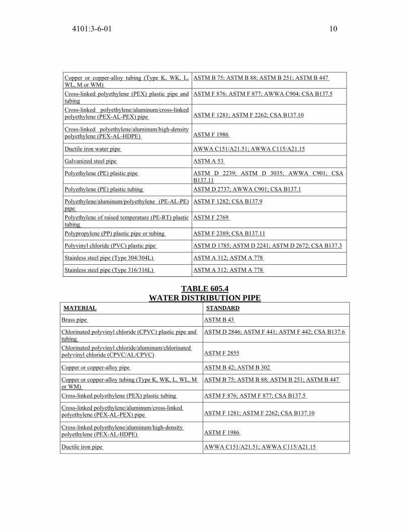
4101:3-6-01 10
Copper or copper-alloy tubing (Type K, WK, L,
WL, M or WM)
ASTM B 75; ASTM B 88; ASTM B 251; ASTM B 447
Cross-linked polyethylene (PEX) plastic pipe and
tubing
ASTM F 876; ASTM F 877; AWWA C904; CSA B137.5
Cross-linked polyethylene/aluminum/cross-linked
polyethylene (PEX-AL-PEX) pipe ASTM F 1281; ASTM F 2262; CSA B137.10
Cross-linked polyethylene/aluminum/high-density
polyethylene (PEX-AL-HDPE) ASTM F 1986
Ductile iron water pipe AWWA C151/A21.51; AWWA C115/A21.15
Galvanized steel pipe ASTM A 53
Polyethylene (PE) plastic pipe ASTM D 2239; ASTM D 3035; AWWA C901; CSA
B137.11
Polyethylene (PE) plastic tubing ASTM D 2737; AWWA C901; CSA B137.1
Polyethylene/aluminum/polyethylene (PE-AL-PE)
pipe
ASTM F 1282; CSA B137.9
Polyethylene of raised temperature (PE-RT) plastic
tubing
ASTM F 2769
Polypropylene (PP) plastic pipe or tubing ASTM F 2389; CSA B137.11
Polyvinyl chloride (PVC) plastic pipe ASTM D 1785; ASTM D 2241; ASTM D 2672; CSA B137.3
Stainless steel pipe (Type 304/304L) ASTM A 312; ASTM A 778
Stainless steel pipe (Type 316/316L) ASTM A 312; ASTM A 778
TABLE 605.4 WATER DISTRIBUTION PIPE
MATERIAL STANDARD
Brass pipe ASTM B 43
Chlorinated polyvinyl chloride (CPVC) plastic pipe and
tubing
ASTM D 2846; ASTM F 441; ASTM F 442; CSA B137.6
Chlorinated polyvinyl chloride/aluminum/chlorinated
polyvinyl chloride (CPVC/AL/CPVC) ASTM F 2855
Copper or copper-alloy pipe ASTM B 42; ASTM B 302
Copper or copper-alloy tubing (Type K, WK, L, WL, M
or WM)
ASTM B 75; ASTM B 88; ASTM B 251; ASTM B 447
Cross-linked polyethylene (PEX) plastic tubing ASTM F 876; ASTM F 877; CSA B137.5
Cross-linked polyethylene/aluminum/cross-linked
polyethylene (PEX-AL-PEX) pipe ASTM F 1281; ASTM F 2262; CSA B137.10
Cross-linked polyethylene/aluminum/high-density
polyethylene (PEX-AL-HDPE) ASTM F 1986
Ductile iron pipe AWWA C151/A21.51; AWWA C115/A21.15

4101:3-6-01 11
Galvanized steel pipe ASTM A 53
Polyethylene/aluminum/polyethylene (PE-AL-PE)
composite pipe
ASTM F 1282
Polyethylene of raised temperature (PE-RT) plastic
tubing
ASTM F 2769
Polypropylene (PP) plastic pipe or tubing ASTM F 2389; CSA B137.11
Stainless steel pipe (Type 304/304L) ASTM A 312; ASTM A 778
Stainless steel pipe (Type 316/316L) ASTM A 312; ASTM A 778
605.7 Valves. Valves shall be compatible with the type of piping material
installed in the system. Valves shall conform to one of the standards listed in
Table 605.7 or shall be approved. Valves intended to supply drinking water shall
meet the requirements of NSF 61.
605.8 Manufactured pipe nipples. Manufactured pipe nipples shall conform to
one of the standards listed in Table 605.8.
TABLE 605.8
MANUFACTURED PIPE NIPPLES
MATERIAL STANDARD
Brass-, copper-, chromium-plated ASTM B 687
Steel ASTM A 733
605.9 Prohibited joints and connections. The following types of joints and
connections shall be prohibited:
1. Cement or concrete joints.
2. Joints made with fittings not approved for the specific installation.
3. Solvent-cement joints between different types of plastic pipe.
4. Saddle-type fittings.
605.10 ABS plastic. Joints between ABS plastic pipe and fittings shall comply
with Sections 605.10.1 through 605.10.3.
605.10.1 Mechanical joints. Mechanical joints on water pipes shall be made
with an elastomeric seal conforming to ASTM D 3139. Mechanical joints
shall only be installed in underground systems, unless otherwise approved. Joints shall be installed only in accordance with the manufacturer’s
instructions.
605.10.2 Solvent cementing. Joint surfaces shall be clean and free from

4101:3-6-01 12
moisture. Solvent cement that conforms to ASTM D 2235 shall be applied to
all joint surfaces. The joint shall be made while the cement is wet. Joints shall
be made in accordance with ASTM D 2235. Solvent-cement joints shall be
permitted above or below ground.
605.10.3 Threaded joints. Threads shall conform to ASME B1.20.1.
Schedule 80 or heavier pipe shall be permitted to be threaded with dies
specifically designed for plastic pipe. Approved thread lubricant or tape shall
be applied on the male threads only.
605.11 Brass. Joints between brass pipe and fittings shall comply with Sections
605.11.1 through 605.11.4.
605.11.1 Brazed joints. All joint surfaces shall be cleaned. An approved flux
shall be applied where required. The joint shall be brazed with a filler metal
conforming to AWS A5.8.
605.11.2 Mechanical joints. Mechanical joints shall be installed in
accordance with the manufacturer’s instructions.
605.11.3 Threaded joints. Threads shall conform to ASME B1.20.1. Pipe-
joint compound or tape shall be applied on the male threads only.
605.11.4 Welded joints. All joint surfaces shall be cleaned. The joint shall
be welded with an approved filler metal.
TABLE 605.5
PIPE FITTINGS
MATERIAL STANDARD
Acrylonitrile butadiene styrene (ABS) plastic ASTM D 2468
Cast iron ASME B16.4
Chlorinated polyvinyl chloride (CPVC)
plastic
ASSE 1061; ASTM D 2846; ASTM F 437; ASTM F 438;
ASTM F 439; CSA B137.6
Copper or copper alloy ASME B16.15; ASME B16.18; ASME B16.22; ASME 16.26;
ASME B16.51; ASSE 1061; ASTM F 1476; ASTM F 1548
Cross-linked polyethylene/aluminum/high-
density polyethylene (PEX-AL-HDPE) ASTM F 1986
Fittings for cross-linked polyethylene (PEX)
plastic tubing
ASSE 1061, ASTM F 877; ASTM F 1807; ASTM F 1960;
ASTM F 2080; ASTM F 2098, ASTM F 2159; ASTM F 2434;
ASTM F 2735; CSA B137.5

4101:3-6-01 13
Fittings for polyethylene of raised
temperature (PE-RT) plastic tubing
ASTM F 1807; ASTM F 2098; ASTM F 2159; ASTM F 2735;
ASTM F 2769
Gray iron and ductile iron ASTM F 1476; ASTM F 1548; AWWA C110/A21.10; AWWA
C153/A21.53;
Insert fittings for
polyethylene/aluminum/polyethylene (PE-
AL-PE) and cross-linked
polyethylene/aluminum/cross-linked
polyethylene (PEX-AL-PEX)
ASTM F 1974; ASTM F 1281; ASTM F 1282; CSA B137.9;
CSA B137.10M
Malleable iron ASME B16.3
Metal (brass) insert fittings for
polyethylene/aluminum/polyethylene (PE-
AL-PE) and cross-linked
polyethylene/aluminum/cross-linked
polyethylene (PEX-AL-PEX)
ASTM F 1974
Polyethylene (PE) plastic pipe ASTM D 2609; ASTM D 2683; ASTM D 3261;
ASTM F 1055; CSA B137.1
Polypropylene (PP) plastic pipe or tubing ASTM F 2389; CSA B137.11
Polyvinyl chloride (PVC) plastic ASTM D 2464; ASTM D 2466; ASTM D 2467; CSA B137.2;
CSA B137.3
Stainless steel (Type 304/304L) ASTM A 312; ASTM A 778; ASTM F 1476; ASTM F 1548
Stainless steel (Type 316/316L) ASTM A 312; ASTM A 778; ASTM F 1476; ASTM F 1548
Steel ASME B16.9; ASME B16.11; ASME B16.28; ASTM F 1476;
ASTM F 1548
TABLE 605.7
VALVES MATERIAL STANDARD
Chlorinated polyvinyl chloride (CPVC)
plastic
ASME A112.4.14; ASME A112.18.1/CSA B125.1; ASTM F
1970; CSA B125.3
Copper or copper alloy
ASME A112.4.14; ASME A112.18.1/CSA B125.1; ASME
B16.34; CSA B125.3;
MSS SP-67; MSS SP-80; MSS SP-110
Cross-linked polyethylene (PEX) plastic ASME A112.4.14; ASME A112.18.1/CSA B125.1; CSA B125.3;
NSF 359
Gray iron and ductile iron
AWWA C500; AWWA C504; AWWA C507; MSS SP-67; MSS
SP-70; MSS SP-71;
MSS SP-72; MSS SP-78
Polypropylene (PP) plastic ASME A112.4.14; ASTM F 2389
Polyvinyl chloride (PVC) plastic ASME A112.4.14; ASTM F 1970
605.12 Gray iron and ductile iron joints. Joints for gray and ductile iron pipe
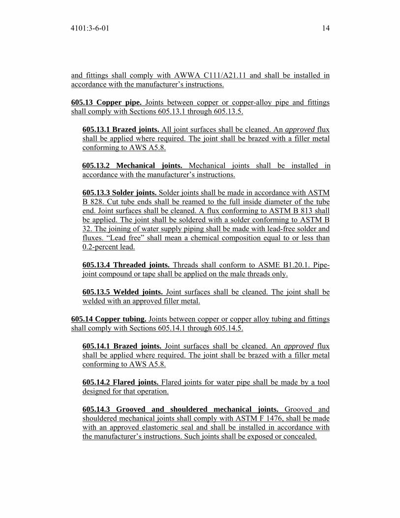
4101:3-6-01 14
and fittings shall comply with AWWA C111/A21.11 and shall be installed in
accordance with the manufacturer’s instructions.
605.13 Copper pipe. Joints between copper or copper-alloy pipe and fittings
shall comply with Sections 605.13.1 through 605.13.5.
605.13.1 Brazed joints. All joint surfaces shall be cleaned. An approved flux
shall be applied where required. The joint shall be brazed with a filler metal
conforming to AWS A5.8.
605.13.2 Mechanical joints. Mechanical joints shall be installed in
accordance with the manufacturer’s instructions.
605.13.3 Solder joints. Solder joints shall be made in accordance with ASTM
B 828. Cut tube ends shall be reamed to the full inside diameter of the tube
end. Joint surfaces shall be cleaned. A flux conforming to ASTM B 813 shall
be applied. The joint shall be soldered with a solder conforming to ASTM B
32. The joining of water supply piping shall be made with lead-free solder and
fluxes. “Lead free” shall mean a chemical composition equal to or less than
0.2-percent lead.
605.13.4 Threaded joints. Threads shall conform to ASME B1.20.1. Pipe-
joint compound or tape shall be applied on the male threads only.
605.13.5 Welded joints. Joint surfaces shall be cleaned. The joint shall be
welded with an approved filler metal.
605.14 Copper tubing. Joints between copper or copper alloy tubing and fittings
shall comply with Sections 605.14.1 through 605.14.5.
605.14.1 Brazed joints. Joint surfaces shall be cleaned. An approved flux
shall be applied where required. The joint shall be brazed with a filler metal
conforming to AWS A5.8.
605.14.2 Flared joints. Flared joints for water pipe shall be made by a tool
designed for that operation.
605.14.3 Grooved and shouldered mechanical joints. Grooved and
shouldered mechanical joints shall comply with ASTM F 1476, shall be made
with an approved elastomeric seal and shall be installed in accordance with
the manufacturer’s instructions. Such joints shall be exposed or concealed.

4101:3-6-01 15
605.14.4 Mechanical joints. Mechanical joints shall be installed in
accordance with the manufacturer’s instructions.
605.14.5 Press-connect joints. Press-connect joints shall conform to one of
the standards listed in Table 605.5, and shall be installed in accordance with
the manufacturer’s instructions. Cut tube ends shall be reamed to the full
inside diameter of the tube end. Joint surfaces shall be cleaned. The tube shall
be fully inserted into the press-connect fitting. Press-connect joints shall be
pressed with a tool certified by the manufacturer.
605.14.6 Solder joints. Solder joints shall be made in accordance with the
methods of ASTM B 828. All cut tube ends shall be reamed to the full inside
diameter of the tube end. All joint surfaces shall be cleaned. A flux
conforming to ASTM B 813 shall be applied. The joint shall be soldered with
a solder conforming to ASTM B 32. The joining of water supply piping shall
be made with lead-free solders and fluxes. “Lead free” shall mean a chemical
composition equal to or less than 0.2-percent lead.
605.15 CPVC plastic. Joints between CPVC plastic pipe and fittings shall
comply with Sections 605.15.1 through 605.15.3.
605.15.1 Mechanical joints. Mechanical joints shall be installed in
accordance with the manufacturer’s instructions.
605.15.2 Solvent cementing. Joint surfaces shall be clean and free from
moisture. Joints shall be made in accordance with the pipe manufacturer’s
installation instructions. Where such instructions require that a primer be
used, the primer shall be applied to the joint surfaces and a solvent cement
orange in color and conforming to ASTM F 493 shall be applied to the joint
surfaces. Where such instructions allow for a one-step solvent cement, yellow
in color and conforming to ASTM F 493, to be used, the joint surfaces shall
not require application of a primer before the solvent cement is applied. The
joint shall be made while the cement is wet and in accordance with ASTM D
2846 or ASTM F 493. Solvent cemented joints shall be permitted above or
below ground.
605.15.3 Threaded joints. Threads shall conform to ASME B1.20.1.
Schedule 80 or heavier pipe shall be permitted to be threaded with dies
specifically designed for plastic pipe, but the pressure rating of the pipe shall
be reduced by 50 percent. Thread by socket molded fittings shall be permitted.

4101:3-6-01 16
Approved thread lubricant or tape shall be applied on the male threads only.
605.16 Chlorinated polyvinyl chloride/aluminum/chlorinated polyvinyl chloride (CPVC/AL/CPVC) pipe and tubing. Joints between CPVC/AL/CPVC
plastic pipe or CPVC fittings shall comply with Sections 605.16.1 and 605.16.2.
605.16.1 Mechanical joints. Mechanical joints shall be installed in
accordance with the manufacturer’s instructions.
605.16.2 Solvent cementing. Joint surfaces shall be clean and free from
moisture, and an approved primer shall be applied. Solvent cement, orange in
color and conforming to ASTM F 493, shall be applied to joint surfaces. The
joint shall be made while the cement is wet, and in accordance with ASTM D
2846 or ASTM F 493. Solvent cement joints shall be permitted above or
below ground.
Exception: A primer is not required where all of the following conditions
apply:
1. The solvent cement used is listed by an approved agency as
conforming to ASTM F 493.
2. The solvent cement used is yellow in color.
3. The solvent cement is used only for joining 1/2inch (12.7 mm) through
2-inch-diameter (51 mm) CPVC/AL/CPVC pipe and CPVC fittings.
4. The CPVC fittings are manufactured in accordance with ASTM D
2846.
605.17 PEX plastic. Joints between cross-linked polyethylene plastic tubing and
fittings shall comply with Sections 605.17.1 and 605.17.2.
605.17.1 Flared joints. Flared pipe ends shall be made by a tool designed for
that operation.
605.17.2 Mechanical joints. Mechanical joints shall be installed in
accordance with the manufacturer’s instructions. Fittings for cross-linked
polyethylene (PEX) plastic tubing shall comply with the applicable standards
listed in Table 605.5 and shall be installed in accordance with the
manufacturer’s instructions. PEX tubing shall be factory marked with the
appropriate standards for the fittings that the PEX manufacturer specifies for
use with the tubing.
605.18 Steel. Joints between galvanized steel pipe and fittings shall comply with
Sections 605.18.1 through 605.18.3.

4101:3-6-01 17
605.18.1 Threaded joints. Threads shall conform to ASME B1.20.1. Pipe-
joint compound or tape shall be applied on the male threads only.
605.18.2 Mechanical joints. Joints shall be made with an approved elastomeric seal. Mechanical joints shall be installed in accordance with the
manufacturer’s instructions.
605.18.3 Grooved and shouldered mechanical joints. Grooved and
shouldered mechanical joints shall comply with ASTM F 1476, shall be made
with an approved elastomeric seal and shall be installed in accordance with
the manufacturer’s instructions. Such joints shall be exposed or concealed.
605.19 PE plastic. Joints between polyethylene plastic pipe or tubing and fittings
shall comply with Sections 605.19.1 through 605.19.4.
605.19.1 Flared joints. Flared joints shall be permitted where so indicated by
the pipe manufacturer. Flared joints shall be made by a tool designed for that
operation.
605.19.2 Heat-fusion joints. Joint surfaces shall be clean and free from
moisture. All joint surfaces shall be heated to melt temperature and joined.
The joint shall be undisturbed until cool. Joints shall be made in accordance
with ASTM D 2657.
605.19.3 Mechanical joints. Mechanical joints shall be installed in
accordance with the manufacturer’s instructions.
605.19.4 Installation. Polyethylene pipe shall be cut square, with a cutter
designed for plastic pipe. Except where joined by heat fusion, pipe ends shall
be chamfered to remove sharp edges. Kinked pipe shall not be installed.
The minimum pipe bending radius shall be not less than 30 pipe diameters, or
the minimum coil radius, whichever is greater. Piping shall not be bent
beyond straightening of the curvature of the coil. Bends shall be prohibited
within 10 pipe diameters of any fitting or valve. Stiffener inserts installed with
compression-type couplings and fittings shall not extend beyond the clamp or
nut of the coupling or fitting.
605.20 Polypropylene (PP) plastic. Joints between PP plastic pipe and fittings
shall comply with Section 605.20.1 or 605.20.2.
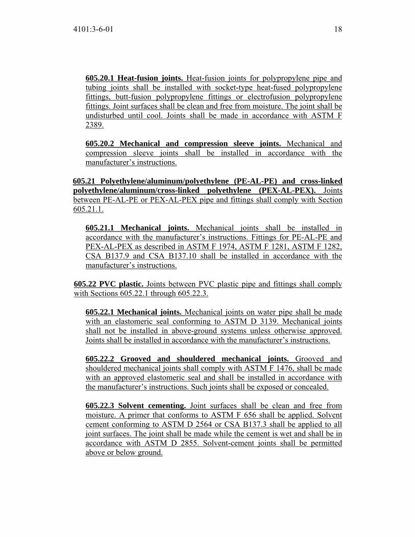
4101:3-6-01 18
605.20.1 Heat-fusion joints. Heat-fusion joints for polypropylene pipe and
tubing joints shall be installed with socket-type heat-fused polypropylene
fittings, butt-fusion polypropylene fittings or electrofusion polypropylene
fittings. Joint surfaces shall be clean and free from moisture. The joint shall be
undisturbed until cool. Joints shall be made in accordance with ASTM F
2389.
605.20.2 Mechanical and compression sleeve joints. Mechanical and
compression sleeve joints shall be installed in accordance with the
manufacturer’s instructions.
605.21 Polyethylene/aluminum/polyethylene (PE-AL-PE) and cross-linked polyethylene/aluminum/cross-linked polyethylene (PEX-AL-PEX). Joints
between PE-AL-PE or PEX-AL-PEX pipe and fittings shall comply with Section
605.21.1.
605.21.1 Mechanical joints. Mechanical joints shall be installed in
accordance with the manufacturer’s instructions. Fittings for PE-AL-PE and
PEX-AL-PEX as described in ASTM F 1974, ASTM F 1281, ASTM F 1282,
CSA B137.9 and CSA B137.10 shall be installed in accordance with the
manufacturer’s instructions.
605.22 PVC plastic. Joints between PVC plastic pipe and fittings shall comply
with Sections 605.22.1 through 605.22.3.
605.22.1 Mechanical joints. Mechanical joints on water pipe shall be made
with an elastomeric seal conforming to ASTM D 3139. Mechanical joints
shall not be installed in above-ground systems unless otherwise approved.
Joints shall be installed in accordance with the manufacturer’s instructions.
605.22.2 Grooved and shouldered mechanical joints. Grooved and
shouldered mechanical joints shall comply with ASTM F 1476, shall be made
with an approved elastomeric seal and shall be installed in accordance with
the manufacturer’s instructions. Such joints shall be exposed or concealed.
605.22.3 Solvent cementing. Joint surfaces shall be clean and free from
moisture. A primer that conforms to ASTM F 656 shall be applied. Solvent
cement conforming to ASTM D 2564 or CSA B137.3 shall be applied to all
joint surfaces. The joint shall be made while the cement is wet and shall be in
accordance with ASTM D 2855. Solvent-cement joints shall be permitted
above or below ground.

4101:3-6-01 19
605.22.4 Threaded joints. Threads shall conform to ASME B1.20.1.
Schedule 80 or heavier pipe shall be permitted to be threaded with dies
specifically designed for plastic pipe, but the pressure rating of the pipe shall
be reduced by 50 percent. Thread by socket molded fittings shall be permitted.
Approved thread lubricant or tape shall be applied on the male threads only.
605.23 Stainless steel. Joints between stainless steel pipe and fittings shall
comply with Sections 605.23.1 and 605.23.3.
605.23.1 Mechanical joints. Mechanical joints shall be installed in
accordance with the manufacturer’s instructions.
605.23.2 Welded joints. All joint surfaces shall be cleaned. The joint shall be
welded autogenously or with an approved filler metal as referenced in ASTM
A 312.
605.23.3 Grooved and shouldered mechanical joints. Grooved and
shouldered mechanical joints shall comply with ASTM F 1476, shall be made
with an approved elastomeric seal and shall be installed in accordance with
the manufacturer’s instructions. Such joints shall be exposed or concealed.
605.24 Joints between different materials. Joints between different piping
materials shall be made with a mechanical joint of the compression or
mechanical-sealing type, or as permitted in Sections 605.24.1, 605.24.2 and
605.24.3. Connectors or adapters shall have an elastomeric seal conforming to
ASTM F 477. Joints shall be installed in accordance with the manufacturer’s
instructions.
605.24.1 Copper or copper-alloy tubing to galvanized steel pipe. Joints
between copper or copper-alloy tubing and galvanized steel pipe shall be
made with a brass fitting or dielectric fitting or a dielectric union conforming
to ASSE 1079. The copper tubing shall be soldered to the fitting in an
approved manner, and the fitting shall be screwed to the threaded pipe.
605.24.2 Plastic pipe or tubing to other piping material. Joints between
different types of plastic pipe or between plastic pipe and other piping
material shall be made with approved adapters or transition fittings.
605.24.3 Stainless steel. Joints between stainless steel and different piping
materials shall be made with a mechanical joint of the compression or
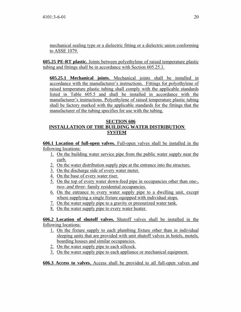
4101:3-6-01 20
mechanical sealing type or a dielectric fitting or a dielectric union conforming
to ASSE 1079.
605.25 PE-RT plastic. Joints between polyethylene of raised temperature plastic
tubing and fittings shall be in accordance with Section 605.25.1.
605.25.1 Mechanical joints. Mechanical joints shall be installed in
accordance with the manufacturer’s instructions. Fittings for polyethylene of
raised temperature plastic tubing shall comply with the applicable standards
listed in Table 605.5 and shall be installed in accordance with the
manufacturer’s instructions. Polyethylene of raised temperature plastic tubing
shall be factory marked with the applicable standards for the fittings that the
manufacturer of the tubing specifies for use with the tubing.
SECTION 606
INSTALLATION OF THE BUILDING WATER DISTRIBUTION SYSTEM
606.1 Location of full-open valves. Full-open valves shall be installed in the
following locations:
1. On the building water service pipe from the public water supply near the
curb.
2. On the water distribution supply pipe at the entrance into the structure.
3. On the discharge side of every water meter.
4. On the base of every water riser.
5. On the top of every water down-feed pipe in occupancies other than one-,
two- and three- family residential occupancies.
6. On the entrance to every water supply pipe to a dwelling unit, except
where supplying a single fixture equipped with individual stops.
7. On the water supply pipe to a gravity or pressurized water tank.
8. On the water supply pipe to every water heater.
606.2 Location of shutoff valves. Shutoff valves shall be installed in the
following locations:
1. On the fixture supply to each plumbing fixture other than in individual
sleeping units that are provided with unit shutoff valves in hotels, motels,
boarding houses and similar occupancies.
2. On the water supply pipe to each sillcock.
3. On the water supply pipe to each appliance or mechanical equipment.
606.3 Access to valves. Access shall be provided to all full-open valves and

4101:3-6-01 21
shutoff valves.
606.4 Valve identification. Service and hose bibb valves shall be identified. All
other valves installed in locations that are not adjacent to the fixture or appliance
shall be identified, indicating the fixture or appliance served.
606.5 Water pressure booster systems. Water pressure booster systems shall be
provided as required by Sections 606.5.1 through 606.5.10.
606.5.1 Water pressure booster systems required. Where the water
pressure in the public water main or individual water supply system is
insufficient to supply the minimum pressures and quantities specified in this
code, the supply shall be supplemented by an elevated water tank, a
hydropneumatic pressure booster system or a water pressure booster pump
installed in accordance with Section 606.5.5.
606.5.2 Support. All water supply tanks shall be supported in accordance
with the building code.
606.5.3 Covers. All water supply tanks shall be covered to keep out
unauthorized persons, dirt and vermin. The covers of gravity tanks shall be
vented with a return bend vent pipe with an area not less than the area of the
down-feed riser pipe, and the vent shall be screened with a corrosion resistant
screen of not less than 16 by 20 mesh per inch (630 by 787 mesh per m).
606.5.4 Overflows for water supply tanks. A gravity or suction water supply
tank shall be provided with an overflow with a diameter not less than that
shown in Table 606.5.4. The overflow outlet shall discharge at a point not less
than 6 inches (152 mm) above the roof or roof drain; floor or floor drain; or
over an open water-supplied fixture. The overflow outlet shall be covered
with a corrosion-resistant screen of not less than 16 by 20 mesh per inch (630
by 787 mesh per m) and by 1/4-inch (6.4 mm) hardware cloth or shall
terminate in a horizontal angle seat check valve. Drainage from overflow
pipes shall be directed so as not to freeze on roof walks.
TABLE 606.5.4
SIZES FOR OVERFLOW PIPES FOR WATER SUPPLY TANKS
MAXIMUM CAPACITY OF WATER SUPPLY LINE TO TANK (gpm)
DIAMETER OF OVERFLOW PIPE
(inches)
0 – 50 2

4101:3-6-01 22
50 – 150 2½
150 – 200 3
200 – 400 4
400 – 700 5
700 – 1,000 6
Over 1,000 8
For SI: 1 inch = 25.4 mm, 1 gallon per minute = 3.785 L/m.
606.5.5 Low-pressure cutoff required on booster pumps. In accordance with rule 3745-95-07 of the Administrative Code, a low-pressure cutoff, a low suction throttling valve, or variable speed suction limiting controls shall be
installed on all booster pumps in a water pressure booster system to prevent
creation of a vacuum or negative pressure on the suction side of the pump
when a positive pressure of 10 psi (68.94 kPa) or less occurs on the suction
side of the pump while the pump is operating. Enforcement of the referenced rule is the responsibility of the local water supplier.
606.5.6 Potable water inlet control and location. Potable water inlets to
gravity tanks shall be controlled by a fill valve or other automatic supply
valve installed so as to prevent the tank from overflowing. The inlet shall be
terminated so as to provide an air gap not less than 4 inches (102 mm) above
the overflow.
606.5.7 Tank drain pipes. A valved pipe shall be provided at the lowest point
of each tank to permit emptying of the tank. The tank drain pipe shall
discharge as required for overflow pipes and shall not be smaller in size than
specified in Table 606.5.7.
TABLE 606.5.7
SIZE OF DRAIN PIPES FOR WATER TANKS
TANK CAPACITY (gallons) DRAIN PIPE (inches)
Up to 750 1
751 to 1,500 1½
1,501 to 3,000 2
3,001 to 5,000 2½
5,000 to 7,500 3
Over 7,500 4
For SI: 1 inch = 25.4 mm, 1 gallon = 3.785 L.

4101:3-6-01 23
606.5.8 Prohibited location of potable supply tanks. Potable water gravity
tanks or manholes of potable water pressure tanks shall not be located directly
under any soil or waste piping or any source of contamination.
606.5.9 Pressure tanks, vacuum relief. All water pressure tanks shall be
provided with a vacuum relief valve at the top of the tank that will operate up
to a maximum water pressure of 200 psi (1380 kPa) and up to a maximum
temperature of 200ºF (93ºC). The size of such vacuum relief valve shall be not
less than 1/2 inch (12.7 mm).
Exception: This section shall not apply to pressurized captive air
diaphragm/bladder tanks.
606.5.10 Pressure relief for tanks. Every pressure tank in a hydropneumatic
pressure booster system shall be protected with a pressure relief valve. The
pressure relief valve shall be set at a maximum pressure equal to the rating of
the tank. The relief valve shall be installed on the supply pipe to the tank or on
the tank. The relief valve shall discharge by gravity to a safe place of disposal.
606.6 Water supply system test. Upon completion of a section of or the entire
water supply system, the system, or portion completed, shall be tested in
accordance with Section 312.
606.7 Labeling of water distribution pipes in bundles. Where water
distribution piping is bundled at installation, each pipe in the bundle shall be indentified using stenciling or commercially available pipe labels. The
identification shall indicate the pipe contents and the direction of flow in the pipe.
The interval of the identification markings on the pipe shall not exceed 25 feet
(7620 mm). There shall be not less than one identification label on each pipe in
each room, space or story.
SECTION 607
HOT WATER SUPPLY SYSTEM
607.1 Where required. In residential occupancies, hot water shall be supplied to
plumbing fixtures and equipment utilized for bathing, washing, culinary purposes,
cleansing, laundry or building maintenance. In nonresidential occupancies, hot
water shall be supplied for culinary purposes, cleansing, laundry or building
maintenance purposes. In nonresidential occupancies, hot water or tempered
water shall be supplied for bathing and washing purposes. Tempered water shall be delivered from public hand-washing facilities.
4101:3-6-01 24
607.1.1 Temperature limiting means. A thermostat control for a water
heater shall not serve as the temperature limiting means for the purposes of
complying with the requirements of this code for maximum allowable hot or
tempered water delivery temperature at fixtures.
607.1.2 Tempered water temperature control. Tempered water shall be
supplied through a water temperature limiting device that conforms to ASSE
1070 and shall limit the tempered water to a maximum of 110ºF (43ºC). This
provision shall not supersede the requirement for protective shower valves in
accordance with Section 424.3.
607.2 Hot or tempered water supply to fixtures. The developed length of hot or
tempered water piping, from the source of hot water to the fixtures that require
hot or tempered water, shall not exceed 50 feet (15 240 mm). Recirculating
system piping and heat-traced piping shall be considered to be sources of hot or
tempered water.
607.2.1 Circulation systems and heat trace systems for maintaining heated water temperature in distribution systems. Automatic circulating hot water system pumps or heat trace shall be arranged to be conveniently turned off, automatically or manually, when the hot water system is not in operation.
607.2.1.1 Pump controls for hot water storage systems. Deleted.
607.2.1.2 Demand recirculation controls for distribution systems. A
water distribution system having one or more recirculation pumps that
pump water from a heated water supply pipe back to the heated water
source through a cold water supply pipe shall be a demand recirculation
water system. Pumps shall have controls that comply with both of the
following:
1. The control shall start the pump upon receiving a signal from the
action of a user of a fixture or appliance, sensing the presence of a
user of a fixture, or sensing the flow of hot or tempered water to a
fixture fitting or appliance.
2. The control shall limit the temperature of the water entering the
cold water piping to 104°F (40°C).
607.2.2 Piping for recirculation systems having master thermostatic valves. Where a thermostatic mixing valve is used in a system with a hot

4101:3-6-01 25
water recirculating pump, the hot water or tempered water return line shall be
routed to the cold water inlet pipe of the water heater and the cold water inlet
pipe or the hot water return connection of the thermostatic mixing valve.
607.3 Thermal expansion control. Where a storage water heater is supplied with
cold water that passes through a check valve, pressure reducing valve or backflow
preventer, a thermal expansion tank shall be connected to the water heater cold
water supply pipe at a point that is downstream of all check valves, pressure
reducing valves and backflow preventers. Thermal expansion tanks shall be sized
in accordance with the tank manufacturer’s instructions and shall be sized such
that the pressure in the water distribution system shall not exceed that required by
Section 604.8.
607.4 Flow of hot water to fixtures. Fixture fittings, faucets and diverters shall
be installed and adjusted so that the flow of hot water from the fittings
corresponds to the left-hand side of the fixture fitting.
Exception: Shower and tub/shower mixing valves conforming to ASSE
1016/ASME A112.1016/CSA B125.16 or ASME A112.18.1/CSA B125.1,
where the flow of hot water corresponds to the markings on the device.
607.5 Insulation of piping. Piping to the inlet of a water heater and piping
conveying water heated by a water heater shall be insulated in accordance with
the applicable energy conservation standard referenced in Chapter 13 of the building code or Chapter 11 of the “Residential Code of Ohio”.
SECTION 608
PROTECTION OF POTABLE WATER SUPPLY
608.1 General. A potable water supply system within a building shall be
designed, installed and maintained in such a manner so as to prevent
contamination from nonpotable liquids, solids or gases being introduced into the
building potable water supply through cross connections or any other piping
connections to the system. Isolation backflow prevention device applications
shall conform to Table 608.1, except as specifically stated in Sections 608.2
through 608.16.10.
608.2 Plumbing fixtures. The supply lines and fittings for plumbing fixtures
shall be installed so as to prevent backflow. Plumbing fixture fittings shall
provide backflow protection in accordance with ASME A112.18.1/CSA B125.1.
608.3 Devices, appurtenances, appliances and apparatus. Devices,

4101:3-6-01 26
appurtenances, appliances and apparatus intended to serve some special function,
such as sterilization, distillation, processing, cooling, or storage of ice or foods,
and that connect to the water supply system, shall be provided with protection
against backflow and contamination of the water supply system. Water pumps,
water-powered sump pumps, filters, softeners, tanks and other appliances and
devices that handle or treat potable water shall be protected against
contamination.
608.3.1 Special equipment, water supply protection. The water supply for
hospital fixtures shall be protected against backflow with a reduced pressure
principle backflow prevention assembly, an atmospheric or spill-resistant
vacuum breaker assembly, or an air gap. Vacuum breakers for bedpan washer
hoses shall not be located less than 5 feet (1524 mm) above the floor.
Vacuum breakers for hose connections in health care or laboratory areas shall
not be less than 6 feet (1829 mm) above the floor.
608.4 Water service piping. Water service piping shall be protected in
accordance with Sections 603.2 and 603.2.1.
608.5 Chemicals and other substances. Chemicals and other substances that
produce either toxic conditions, taste, odor or discoloration in a potable water
system shall not be introduced into, or utilized in, such systems.
608.6 Cross connection control. Cross connections shall be prohibited, except
where approved backflow prevention assemblies, backflow prevention devices or
other means or methods are installed to protect the potable water supply.
608.6.1 Private water supplies. Cross connections between a private water
supply and a potable public supply shall be prohibited.
608.7 Valves and outlets prohibited below grade. Potable water outlets and
combination stop-and-waste valves shall not be installed underground or below
grade. Freezeproof yard hydrants that drain the riser into the ground are
considered to be stop-and-waste valves.
Exception: Freezeproof yard hydrants that drain the riser into the ground shall
be permitted to be installed, provided that the potable water supply to such
hydrants is protected upstream of the hydrants in accordance with Section 608
and the hydrants are permanently identified as nonpotable outlets by approved
signage that reads as follows: “Caution, Nonpotable Water. Do Not Drink.”
608.8 Identification of nonpotable water systems. Where nonpotable water

4101:3-6-01 27
systems are installed, the piping conveying the nonpotable water shall be
identified either by color marking, metal tags or tape in accordance with Sections
608.8.1 through 608.8.2.3.
608.8.1 Signage required. Nonpotable water outlets, such as hose
connections, open ended pipes and faucets, shall be identified with signage
that reads as follows: “Nonpotable water is utilized for [application name].
CAUTION: NONPOTABLE WATER – DO NOT DRINK.”
The words shall be legibly and indelibly printed on a tag or sign constructed
of corrosion-resistant waterproof material or shall be indelibly printed on the
fixture. The letters of the words shall be not less than 0.5 inch (12.7 mm) in
height and in colors in contrast to the background on which they are applied.
In addition to the required wordage, the pictograph shown in Figure 608.8.1
shall appear on the required signage.
FIGURE 608.8.1 PICTOGRAPH—DO NOT DRINK
608.8.2 Distribution pipe labeling and marking. Nonpotable distribution
piping shall be purple in color and shall be embossed, or integrally stamped or
marked, with the words: “CAUTION: NONPOTABLE WATER – DO NOT
DRINK” or the piping shall be installed with a purple identification tape or
wrap. Pipe identification shall include the contents of the piping system and
an arrow indicating the direction of flow. Hazardous piping systems shall also
contain information addressing the nature of the hazard. Pipe identification
shall be repeated at intervals not exceeding 25 feet (7620 mm) and at each
point where the piping passes through a wall, floor or roof. Lettering shall be
readily observable within the room or space where the piping is located.

4101:3-6-01 28
608.8.2.1 Color. The color of the pipe identification shall be discernable
and consistent throughout the building. The color purple shall be used to
identify reclaimed, rain and gray water distribution systems.
608.8.2.2 Lettering size. The size of the background color field and
lettering shall comply with Table 608.8.2.2.
TABLE 608.8.2.2
SIZE OF PIPE IDENTIFICATION
PIPE DIAMETER (inches)
LENGTH BACKGROUND
COLOR FIELD
(inches)
SIZE OF LETTERS (inches)
¾ to 1 ¼
8 0.5
11/2 to 2 8 0.75
21/2 to 6 12 1.25
8 to 10 24 2.5
over 10 32 3.5
For SI 1 inch = 25.4 mm.
608.8.2.3 Identification tape. Where used, identification tape shall be at
least 3 inches (76 mm) wide and have white or black lettering on a purple
field stating
“CAUTION: NONPOTABLE WATER – DO NOT DRINK.”
Identification tape shall be installed on top of nonpotable rainwater
distribution pipes, fastened at least every 10 feet (3048 mm) to each pipe
length and run continuously the entire length of the pipe.
608.9 Reutilization prohibited. Water utilized for the cooling of equipment or
other processes shall not be returned to the potable water system. Such water shall
be discharged into a drainage system through an air gap or shall be utilized for
nonpotable purposes. 608.10 Reuse of piping. Piping that has been utilized for any purpose other than
conveying potable water shall not be utilized for conveying potable water.
TABLE 608.1 APPLICATION OF BACKFLOW PREVENTERS

4101:3-6-01 29
DEVICE DEGREE OF HAZARD a
APPLICATION b APPLICABLE STANDARDS
Backflow prevention assemblies:
Double check
backflow
prevention
assembly and
double check fire
protection
backflow
prevention
assembly
Low hazard Backpressure or backsiphonage
Sizes 3/8"–16"
ASSE 1015, AWWA
C510,
CSA B64.5, CSA
B64.5.1
Double check
detector fire
protection
backflow prevention
assemblies
Low hazard
Backpressure or backsiphonage
Sizes 2"–16"
ASSE 1048
Pressure vacuum
breaker assembly
High or low hazard Backsiphonage only Sizes 1/2"–2" ASSE 1020, CSA
B64.1.2
Reduced pressure
principle backflow
prevention assembly
and reduced pressure
principle fire
protection backflow
assembly
High or low hazard Backpressure or backsiphonage
Sizes 3/8"–16"
ASSE 1013, AWWA
C511,
CSA B64.4, CSA
B64.4.1
Reduced pressure
detector fire protection
backflow prevention
assemblies
High or low hazard
Backsiphonage or backpressure
(Fire sprinkler systems) ASSE 1047
Spill-resistant vacuum
breaker assembly High or low hazard
Backsiphonage only
Sizes 1/4"–2" ASSE 1056
Backflow preventer plumbing devices:
Antisiphon-type
fill valves for
gravity water
closet flush tanks
High hazard Backsiphonage only ASSE 1002, CSA
B125.3
Backflow
preventer for
carbonated
beverage
machines
Low hazard
Backpressure or backsiphonage
Sizes 1/4"–3/8"
ASSE 1022
Backflow preventer
with intermediate
atmospheric vents
Low hazard
Backpressure or backsiphonage
Sizes 1/4"–3/4" ASSE 1012, CSA B64.3
Dual-check-valve-type
backflow preventer Low hazard
Backpressure or backsiphonage
Sizes 1/4"–1" ASSE 1024, CSA B64.6
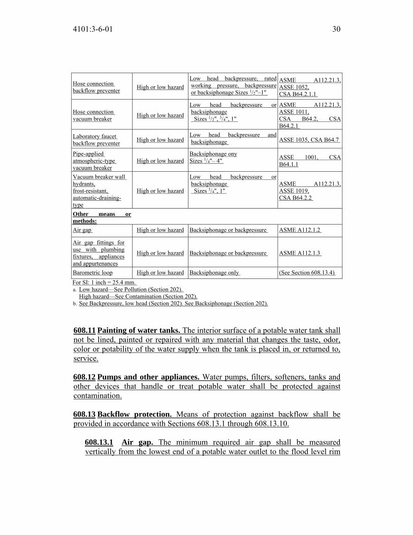
4101:3-6-01 30
Hose connection
backflow preventer High or low hazard
Low head backpressure, rated
working pressure, backpressure
or backsiphonage Sizes 1/2"–1"
ASME A112.21.3,
ASSE 1052,
CSA B64.2.1.1
Hose connection
vacuum breaker High or low hazard
Low head backpressure or
backsiphonage
Sizes 1/2", 3/4", 1"
ASME A112.21.3,
ASSE 1011,
CSA B64.2, CSA
B64.2.1
Laboratory faucet
backflow preventer High or low hazard
Low head backpressure and
backsiphonage ASSE 1035, CSA B64.7
Pipe-applied
atmospheric-type
vacuum breaker
High or low hazard
Backsiphonage ony
Sizes 1/4"– 4" ASSE 1001, CSA
B64.1.1
Vacuum breaker wall
hydrants,
frost-resistant,
automatic-draining-
type
High or low hazard
Low head backpressure or
backsiphonage
Sizes 3/4", 1"
ASME A112.21.3,
ASSE 1019,
CSA B64.2.2
Other means or methods:
Air gap High or low hazard Backsiphonage or backpressure ASME A112.1.2
Air gap fittings for
use with plumbing
fixtures, appliances
and appurtenances
High or low hazard Backsiphonage or backpressure ASME A112.1.3
Barometric loop High or low hazard Backsiphonage only (See Section 608.13.4)
For SI: 1 inch = 25.4 mm.
a. Low hazard—See Pollution (Section 202).
High hazard—See Contamination (Section 202).
b. See Backpressure, low head (Section 202). See Backsiphonage (Section 202).
608.11 Painting of water tanks. The interior surface of a potable water tank shall
not be lined, painted or repaired with any material that changes the taste, odor,
color or potability of the water supply when the tank is placed in, or returned to,
service.
608.12 Pumps and other appliances. Water pumps, filters, softeners, tanks and
other devices that handle or treat potable water shall be protected against
contamination.
608.13 Backflow protection. Means of protection against backflow shall be
provided in accordance with Sections 608.13.1 through 608.13.10.
608.13.1 Air gap. The minimum required air gap shall be measured
vertically from the lowest end of a potable water outlet to the flood level rim

4101:3-6-01 31
of the fixture or receptacle into which such potable water outlet discharges.
Air gaps shall comply with ASME A112.1.2 and air gap fittings shall comply
with ASME A112.1.3.
608.13.2 Reduced pressure principle backflow prevention assemblies.
Reduced pressure principle backflow prevention assemblies shall conform to
ASSE 1013, AWWA C511, CSA B64.4 or CSA B64.4.1. Reduced pressure
detector assembly backflow preventers shall conform to ASSE 1047. These
devices shall be permitted to be installed where subject to continuous pressure
conditions. The relief opening shall discharge by air gap and shall be
prevented from being submerged.
608.13.3 Backflow preventer with intermediate atmospheric vent. Backflow preventers with intermediate atmospheric vents shall conform to
ASSE 1012 or CSA B64.3. These devices shall be permitted to be installed
where subject to continuous pressure conditions. The relief opening shall
discharge by air gap and shall be prevented from being submerged.
608.13.4 Barometric loop. Barometric loops shall precede the point of
connection and shall extend vertically to a height of 35 feet (10 668 mm). A
barometric loop shall only be utilized as an atmospheric-type or pressure-type
vacuum breaker.
608.13.5 Pressure vacuum breaker assemblies. Pressure vacuum breaker
assemblies shall conform to ASSE 1020 or CSA B64.1.2. Spill-resistant
vacuum breaker assemblies shall comply with ASSE 1056. These assemblies
are designed for installation under continuous pressure conditions where the
critical level is installed at the required height. Pressure vacuum breaker
assemblies shall not be installed in locations where spillage could cause
damage to the structure.
608.13.6 Atmospheric-type vacuum breakers. Pipe-applied atmospheric-
type vacuum breakers shall conform to ASSE 1001 or CSA B64.1.1. Hose-
connection vacuum breakers shall conform to ASME A112.21.3, ASSE 1011,
ASSE 1019, ASSE 1035, ASSE 1052, CSA B64.2, CSA B64.2.1, CSA
B64.2.1.1, CSA B64.2.2 or CSA B64.7. These devices shall operate under
normal atmospheric pressure when the critical level is installed at the required
height.
608.13.7 Double check backflow prevention assemblies. Double check
backflow prevention assemblies shall conform to ASSE 1015, CSA B64.5,
4101:3-6-01 32
CSA B64.5.1 or AWWA C510. Double check detector fire protection
backflow prevention assemblies shall conform to ASSE 1048. These
assemblies shall be capable of operating under continuous pressure
conditions.
608.13.8 Spill-resistant pressure vacuum breaker assemblies. Spill-
resistant pressure vacuum breaker assemblies shall conform to ASSE 1056 or
CSA B64.1.3. These assemblies are designed for installation under
continuous-pressure conditions where the critical level is installed at the
required height.
608.13.9 Chemical dispenser backflow devices. Backflow devices for
chemical dispensers shall comply with ASSE 1055 or shall be equipped with
an air gap fitting.
608.13.10 Dual check backflow preventer. Dual check backflow preventers
shall conform to ASSE 1024 or CSA B64.6.
608.14 Location of backflow preventers. Access shall be provided to backflow
preventers as specified by the manufacturer’s instructions.
608.14.1 Outdoor enclosures for backflow prevention devices. Outdoor
enclosures for backflow prevention devices shall comply with ASSE 1060.
608.14.2 Protection of backflow preventers. Backflow preventers shall not
be located in areas subject to freezing except where they can be removed by
means of unions or are protected from freezing by heat, insulation or both.
608.14.2.1 Relief port piping. The termination of the piping from the
relief port or air gap fitting of a backflow preventer shall discharge to an
approved indirect waste receptor or to the outdoors where it will not cause
damage or create a nuisance.
608.15 Protection of potable water outlets. All potable water openings and
outlets shall be protected against backflow in accordance with Section 608.15.1,
608.15.2, 608.15.3, 608.15.4, 608.15.4.1 or 608.15.4.2.
608.15.1 Protection by air gap. Openings and outlets shall be protected by
an air gap between the opening and the fixture flood level rim as specified in
Table 608.15.1. Openings and outlets equipped for hose connection shall be
protected by means other than an air gap.

4101:3-6-01 33
608.15.2 Protection by reduced pressure principle backflow prevention assembly. Openings and outlets shall be protected by a reduced pressure
principle backflow prevention assembly or a reduced pressure principle fire
protection backflow prevention assembly on potable water supplies.
608.15.3 Protection by a backflow preventer with intermediate atmospheric vent. Openings and outlets shall be protected by a backflow
preventer with an intermediate atmospheric vent.
608.15.4 Protection by a vacuum breaker. Openings and outlets shall be
protected by atmospheric-type or pressure type vacuum breakers. The critical
level of the vacuum breaker shall be set not less than 6 inches (152 mm) above
the flood level rim of the fixture or device. Fill valves shall be set in
accordance with Section 425.3.1. Vacuum breakers shall not be installed under
TABLE 608.15.1 MINIMUM REQUIRED AIR GAPS
FIXTURE
MINIMUM AIR GAP
Away from a walla
(inches)Close to a wall (inches)
Lavatories and other fixtures with
effective openings not greater than 1/2 inch in diameter
1 1½
Sinks, laundry trays, gooseneck
back faucets and other fixtures with
effective openings not greater
than 3/4 inch in diameter
1½ 2½
Over-rim bath fillers and other
fixtures with effective openings not
greater than 1 inch in diameter
2 3
Drinking water fountains, single
orifice not greater than 7/16 inch in
diameter or multiple orifices
with a total area of 0.150 square
inch (area of circle 7/16 inch in
diameter)
1 1½
Effective openings greater than 1
inch
Two times the diameter
of the effective opening
Three times the diameter of the effective
opening
For SI: 1 inch = 25.4 mm, 1 square inch = 645 mm2.
a. Applicable where walls or obstructions are spaced from the nearest inside-edge of the spout opening a
distance greater than three times the diameter of the effective opening for a single wall, or a distance
greater than four times the diameter of the effective opening for two intersecting walls.

4101:3-6-01 34
exhaust hoods or similar locations that will contain toxic fumes or vapors.
Pipe-applied vacuum breakers shall be installed not less than 6 inches (152
mm) above the flood level rim of the fixture, receptor or device served.
608.15.4.1 Deck-mounted and integral vacuum breakers. Approved
deck-mounted or equipment mounted vacuum breakers and faucets with
integral atmospheric vacuum breakers or spill-resistant vacuum breaker
assemblies shall be installed in accordance with the manufacturer’s
instructions and the requirements for labeling with the critical level not
less than 1 inch (25 mm) above the flood level rim.
608.15.4.2 Hose connections. Sillcocks, hose bibbs, wall hydrants and
other openings with a hose connection shall be protected by an
atmospheric-type or pressure-type vacuum breaker or a permanently
attached hose connection vacuum breaker.
Exceptions: 1. This section shall not apply to water heater and boiler drain valves
that are provided with hose connection threads and that are
intended only for tank or vessel draining.
2. This section shall not apply to water supply valves intended for
connection of clothes washing machines where backflow
prevention is otherwise provided or is integral with the machine.
608.16 Connections to the potable water system. Connections to the potable
water system shall conform to Sections 608.16.1 through 608.16.10.
608.16.1 Beverage dispensers. The water supply connection to beverage
dispensers shall be protected against backflow by a backflow preventer
conforming to ASSE 1022 or by an air gap. The portion of the backflow
preventer device downstream from the second check valve and the piping
downstream therefrom shall not be affected by carbon dioxide gas.
608.16.2 Connections to boilers. The potable supply to the boiler shall be
equipped with a backflow preventer with an intermediate atmospheric vent
complying with ASSE 1012 or CSA B64.3. Where conditioning chemicals are
introduced into the system, the potable water connection shall be protected by
an air gap or a reduced pressure principle backflow preventer, complying with
ASSE 1013, CSA B64.4 or AWWA C511. If the boiler feedwater, water treatment, or make-up water pipe is not provided with a high temperature check valve (rated at not less than 250 ºF) near the boiler stop valve, then the temperature rating of the backflow preventer shall be not less than 250 ºF.

4101:3-6-01 35
608.16.3 Heat exchangers. Heat exchangers utilizing an essentially toxic
transfer fluid shall be separated from the potable water by double-wall
construction. An air gap open to the atmosphere shall be provided between the
two walls. Heat exchangers utilizing an essentially nontoxic transfer fluid
shall be permitted to be of single-wall construction.
608.16.4 Connections to automatic fire sprinkler systems and standpipe systems. The potable water supply to automatic fire sprinkler and standpipe
systems shall be protected against backflow by a double check backflow
prevention assembly, a double check fire protection backflow prevention
assembly or a reduced pressure principle fire protection backflow prevention
assembly.
Exceptions: 1. Where systems are installed as a portion of the water distribution
system in accordance with the requirements of this code and are not
provided with a fire department connection, isolation of the water
supply system shall not be required.
2. Isolation of the water distribution system is not required for deluge,
preaction or dry pipe systems.
608.16.4.1 Additives or nonpotable source. Where systems under
continuous pressure contain chemical additives or antifreeze, or where
systems are connected to a nonpotable secondary water supply, the potable
water supply shall be protected against backflow by a reduced pressure
principle backflow prevention assembly or a reduced pressure principle
fire protection backflow prevention assembly. Where chemical additives
or antifreeze are added to only a portion of an automatic fire sprinkler or
standpipe system, the reduced pressure principle backflow prevention
assembly or the reduced pressure principle fire protection backflow
prevention assembly shall be permitted to be located so as to isolate that
portion of the system. Where systems are not under continuous pressure,
the potable water supply shall be protected against backflow by an air gap
or an atmospheric vacuum breaker conforming to ASSE 1001 or CSA
B64.1.1.
608.16.5 Connections to lawn irrigation systems. The potable water
supply to lawn irrigation systems shall be protected against backflow by an
atmospheric vacuum breaker, a pressure vacuum breaker assembly or a
reduced pressure principle backflow prevention assembly. Valves shall not be
installed downstream from an atmospheric vacuum breaker. Where chemicals

4101:3-6-01 36
are introduced into the system, the potable water supply shall be protected
against backflow by a reduced pressure principle backflow prevention
assembly.
608.16.6 Connections subject to backpressure. Where a potable water
connection is made to a nonpotable line, fixture, tank, vat, pump or other
equipment subject to high-hazard backpressure, the potable water connection
shall be protected by a reduced pressure principle backflow prevention
assembly.
608.16.7 Chemical dispensers. Where chemical dispensers connect to the
potable water distribution system, the water supply system shall be protected
against backflow in accordance with Section 608.13.1, 608.13.2, 608.13.5,
608.13.6, 608.13.8 or 608.13.9.
608.16.8 Portable cleaning equipment. Where the portable cleaning
equipment connects to the water distribution system, the water supply system
shall be protected against backflow in accordance with Section 608.13.1,
608.13.2, 608.13.3, 608.13.7 or 608.13.8.
608.16.9 Dental pump equipment. Where dental pumping equipment
connects to the water distribution system, the water supply system shall be
protected against backflow in accordance with Section 608.13.1, 608.13.2,
608.13.5, 608.13.6 or 608.13.8.
608.16.10 Coffee machines and noncarbonated beverage dispensers. The
water supply connection to coffee machines and noncarbonated beverage
dispensers shall be protected against backflow by a backflow preventer
conforming to ASSE 1022 or by an air gap.
608.17 Protection of individual water supplies. An individual water supply,
otherwise known as a private water system, shall be located and constructed so as
to be safeguarded against contamination in accordance with the rules of the “Ohio Department of Health” set forth in Chapter 3701-28 of the Administrative Code, “Private Water Systems.”
608.17.1 Well locations. Deleted. TABLE 608.17.1 Deleted. 608.17.2 Elevation. Deleted. 608.17.3 Depth. Deleted. 608.17.4 Water-tight casings. Deleted.

4101:3-6-01 37
608.17.5 Drilled or driven well casings. Deleted. 608.17.6 Dug or bored well casings. Deleted. 608.17.7 Cover. Deleted. 608.17.8 Drainage. Deleted.
SECTION 609
HEALTH CARE PLUMBING
609.1 Scope. This section shall govern those aspects of health care plumbing
systems that differ from plumbing systems in other structures. Health care
plumbing systems shall conform to the requirements of this section in addition to
the other requirements of this code. The provisions of this section shall apply to
the special devices and equipment installed and maintained in the following
occupancies: nursing homes, homes for the aged, orphanages, infirmaries, first
aid stations, psychiatric facilities, clinics, professional offices of dentists and
doctors, mortuaries, educational facilities, surgery, dentistry, research and testing
laboratories, establishments manufacturing pharmaceutical drugs and medicines
and other structures with similar apparatus and equipment classified as plumbing.
609.2 Water service. Hospitals shall have two water service pipes installed in
such a manner so as to minimize the potential for an interruption of the supply of
water in the event of a water main or water service pipe failure.
609.3 Hot water. Hot water shall be provided to supply all of the hospital
fixture, kitchen and laundry requirements. Special fixtures and equipment shall
have hot water supplied at a temperature specified by the manufacturer. The hot
water system shall be installed in accordance with Section 607.
609.4 Vacuum breaker installation. Vacuum breakers shall be installed not
less than 6 inches (152 mm) above the flood level rim of the fixture or device in
accordance with Section 608. The flood level rim of hose connections shall be the
maximum height at which any hose is utilized.
609.5 Prohibited water closet and clinical sink supply. Jet or water-supplied
orifices, except those supplied by the flush connections, shall not be located in or
connected with a water closet bowl or clinical sink. This section shall not prohibit
an approved bidet installation.
609.6 Clinical, hydrotherapeutic and radiological equipment. Clinical,
hydrotherapeutic, radiological or any equipment that is supplied with water or

4101:3-6-01 38
that discharges to the waste system shall conform to the requirements of this
section and Section 608.
609.7 Condensate drain trap seal. A water supply shall be provided for
cleaning, flushing and resealing the condensate trap, and the trap shall discharge
through an air gap in accordance with Section 608.
609.8 Valve leakage diverter. Each water sterilizer filled with water through
directly connected piping shall be equipped with an approved leakage diverter or
bleed line on the water supply control valve to indicate and conduct any leakage
of unsterile water away from the sterile zone.
SECTION 610
DISINFECTION OF PO TABLE WATER SYSTEM
610.1 General. New potable water systems shall be purged of deleterious matter
and disinfected prior to utilization. The method to be followed shall be that
prescribed by the health authority or water purveyor having jurisdiction or, in the
absence of a prescribed method, the procedure described in either AWWA C651
or AWWA C652, or as described in this section. This requirement shall apply to
“on-site” or “inplant” fabrication of a system or to a modular portion of a system.
1. The pipe system shall be flushed with clean, potable water until dirty
water does not appear at the points of outlet.
2. The system or part thereof shall be filled with a water/chlorine solution
containing not less than 50 parts per million (50 mg/L) of chlorine, and the
system or part thereof shall be valved off and allowed to stand for 24
hours; or the system or part thereof shall be filled with a water/chlorine
solution containing not less than 200 parts per million (200 mg/L) of
chlorine and allowed to stand for 3 hours.
3. Following the required standing time, the system shall be flushed with
clean potable water until the chlorine is purged from the system.
4. The procedure shall be repeated where shown by a bacteriological
examination that contamination remains present in the system.
SECTION 611
DRINKING WATER TREATMENT UNITS
611.1 Design. Drinking water treatment units shall meet the requirements of
NSF 42, NSF 44, NSF 53, NSF 62 or CSA B483.1.

4101:3-6-01 39
611.2 Reverse osmosis systems. The discharge from a reverse osmosis drinking
water treatment unit shall enter the drainage system through an air gap or an air
gap device that meets the requirements of NSF 58 or CSA B483.1.
611.3 Connection tubing. The tubing to and from drinking water treatment
units shall be of a size and material as recommended by the manufacturer. The
tubing shall comply with NSF 14, NSF 42, NSF 44, NSF 53, NSF 58 or NSF 61.
SECTION 612
SOLAR SYSTEMS
612.1 Solar systems. The construction, installation, alterations and repair of
systems, equipment and appliances intended to utilize solar energy for space
heating or cooling, domestic hot water heating, swimming pool heating or process
heating shall be in accordance with the mechanical code.
SECTION 613 TEMPERATURE CONTROL DEVICES AND VALVES
613.1 Temperature-actuated mixing valves. Temperature-actuated mixing
valves, which are installed to reduce water temperatures to defined limits, shall
comply with ASSE 1017. Such valves shall be installed at the hot water source.

Replaces: 4101:3-6-01
Effective: 11/01/2017
Five Year Review (FYR) Dates: 11/01/2022
CERTIFIED ELECTRONICALLY
Certification
05/26/2017
Date
Promulgated Under: 119.03Statutory Authority: 3781.10(A), 4104.43(A)(1)Rule Amplifies: 3781.10, 3781.11, 3791.04Prior Effective Dates: 3/1/98, 10/1/99, 12/1/00, 1/1/02, 3/1/05, 7/1/07,
11/1/07, 11/1/11, 7/1/14, 1/1/16
4101:3-6-01 40

4101:3-7-01 Sanitary Drainage.
[Comment: When a reference is made within this rule to a federal statutory provision, an industry consensus standard, or any other technical publication, the specific date and title of the publication as well as the name and address of the promulgating agency are listed in rule 4101:3-15-01 of the Administrative Code. The application of the referenced standards shall be limited and as prescribed in section 102.5 of rule 4101:1-1-01 of the Administrative Code.]
SECTION 701 GENERAL
701.1 Scope. The provisions of this chapter shall govern the materials, design,
construction and installation of sanitary drainage systems. In accordance with section 3781.03 of the Revised Code, the department of the city engineer, in cities having such departments, the boards of health districts, or the sewer purveyor, as appropriate, shall have complete supervision and regulation of the entire sewerage and drainage system of the jurisdiction, including the building sewer and all laterals draining into the street sewers.
Exception: Private sewage disposal systems within the scope of the “Ohio Department of Health” rules contained within Chapter 3701-29 of the Administrative Code, “Household Sewage Disposal Systems”.
701.2 Sewer required. Except where permitted by the “Ohio Environmental Protection Agency”, every building in which plumbing fixtures are installed and
premises having drainage piping shall be connected to a public sewer, where
available, or an approved private sewage disposal system.
701.3 Separate sewer connection. Except where permitted by the “Ohio Environmental Protection Agency”, every building having plumbing fixtures
installed and intended for human habitation, occupancy or use on premises
abutting on a street, alley or easement in which there is a public sewer shall have
a separate connection with the sewer. Where located on the same lot, multiple
buildings shall not be prohibited from connecting to a common building sewer
that connects to the public sewer.
701.4 Sewage treatment. Sewage or other waste from a plumbing system that is
deleterious to surface or subsurface waters shall not be discharged into the ground
or into any waterway without prior approval from the “Ohio Environmental Protection Agency” for the form of treatment and for the location of discharge.
ACTION: Final DATE: 05/26/2017 2:37 PM
RB p(170947) pa(315228) d(672533) ra(523778) print date: 06/01/2017 8:33 AM

4101:3-7-01 2
701.5 Damage to drainage system or public sewer. Except where permitted by the “Ohio Environmental Protection Agency”, wastes detrimental to the public
sewer system or to the functioning of the sewage-treatment plant shall be treated
and disposed of in accordance with requirements of the local sewer purveyor.
701.6 Tests. The sanitary drainage system shall be tested in accordance with
Section 312.
701.7 Engineered systems. Engineered sanitary drainage systems shall conform
to the provisions of Sections 106.5 of the building code and 714.
701.8 Drainage piping in food service areas. Exposed soil or waste piping shall
not be installed above any areas used for food preparation or storage, or above storage or eating surfaces in food service establishments.
SECTION 702 MATERIALS
702.1 Above-ground sanitary drainage and vent pipe. Above-ground soil,
waste and vent pipe shall conform to one of the standards listed in Table 702.1.
702.2 Underground building sanitary drainage and vent pipe. Underground
building sanitary drainage and vent pipe shall conform to one of the standards
listed in Table 702.2.
702.3 Building sewer pipe. Deleted.
TABLE 702.1
ABOVE-GROUND DRAINAGE AND VENT PIPE MATERIAL STANDARD
Acrylonitrile butadiene styrene
(ABS) plastic pipe in IPS
diameters, including Schedule
40, DR 22 (PS 200) and DR
24 (PS 140); with a solid,
cellular core or composite
wall
ASTM D 2661; ASTM F 628;
ASTM F 1488; CSA B181.1
Brass pipe ASTM B 43
Cast-iron pipe ASTM A 74; ASTM A 888;
CISPI 301
Copper or copper-alloy pipe ASTM B 42; ASTM B 302
Copper or copper-alloy tubing
(Type K, L, M or DWV)
ASTM B 75; ASTM B 88;
ASTM B 251; ASTM B 306

4101:3-7-01 3
Galvanized steel pipe ASTM A 53
Glass pipe ASTM C 1053
Polyolefin pipe ASTM F 1412;
CSA B181.3
Polyvinyl chloride (PVC) plastic
pipe in IPS diameters, incluing
Schedule 40, DR 22 (PS 200),
and DR 24 (PS 140);
with a solid, cellular core or
composite wall
ASTM D 2665; ASTM F 891;
ASTM F 1488; CSA B181.2
Polyvinyl chloride (PVC)
plastic pipe with a 3.25-inch
O.D. and a solid, cellular
core or composite wall
ASTM D 2949, ASTM F 1488
Polyvinylidene fluoride
(PVDF) plastic pipe
ASTM F 1673; CSA B181.3
Stainless steel drainage
systems, Types 304 and 316L
ASME A112.3.1
702.4 Fittings. Pipe fittings shall be approved for installation with the piping
material installed and shall comply with the applicable standards listed in Table
702.4.
702.5 Temperature rating. Where the waste water temperature will be greater
than 140°F (60°C), the sanitary drainage piping material shall be rated for the
highest temperature of the waste water.
702.6 Chemical waste system. A chemical waste system shall be completely
separated from the sanitary drainage system. The chemical waste shall be treated
in accordance with Section 803.2 before discharging to the sanitary drainage
system. Separate drainage systems for chemical wastes and vent pipes shall be of
an approved material that is resistant to corrosion and degradation for the
concentrations of chemicals involved.
702.7 Lead bends and traps. The wall thickness of lead bends and traps shall be
not less than 1/8 inch (3.2 mm).
TABLE 702.2 UNDERGROUND BUILDING DR AINAGE AND VENT PIPE
MATERIAL STANDARD
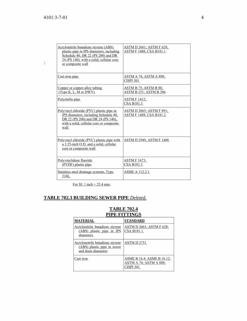
4101:3-7-01 4
\
For SI: 1 inch = 25.4 mm.
TABLE 702.3 BUILDING SEWER PIPE Deleted.
TABLE 702.4
PIPE FITTINGS
MATERIAL STANDARD
Acrylonitrile butadiene styrene
(ABS) plastic pipe in IPS
diameters
ASTM D 2661; ASTM F 628;
CSA B181.1
Acrylonotrile butadiene styrene
(ABS) plastic pipe in sewer
and drain diameters
ASTM D 2751
Cast iron ASME B 16.4; ASME B 16.12;
ASTM A 74; ASTM A 888;
CISPI 301
Acrylonitrile butadiene styrene (ABS)
plastic pipe in IPS diameters, including
Schedule 40, DR 22 (PS 200) and DR
24 (PS 140); with a solid, cellular core
or composite wall
ASTM D 2661; ASTM F 628;
ASTM F 1488; CSA B181.1
Cast-iron pipe ASTM A 74; ASTM A 888;
CISPI 301
Copper or copper-alloy tubing
(Type K, L, M or DWV)
ASTM B 75; ASTM B 88;
ASTM B 251; ASTM B 306
Polyolefin pipe ASTM F 1412;
CSA B181.3
Polyvinyl chloride (PVC) plastic pipe in
IPS diameters, including Schedule 40,
DR 22 (PS 200) and DR 24 (PS 140);
with a solid, cellular core or composite
wall
ASTM D 2665; ASTM F 891;
ASTM F 1488; CSA B181.2
Polyvinyl chloride (PVC) plastic pipe with
a 3.25-inch O.D. and a solid, cellular
core or composite wall
ASTM D 2949, ASTM F 1488
Polyvinylidene fluoride
(PVDF) plastic pipe
ASTM F 1673;
CSA B181.3
Stainless steel drainage systems, Type
316L
ASME A 112.3.1

4101:3-7-01 5
Copper or copper alloy ASME B 16.15; ASME B 16.18;
ASME B 16.22; ASME B 16.23;
ASME B 16.26; ASME B 16.29
Glass ASTM C 1053
Gray iron and ductile iron AWWA C 110/A21.10
Malleable iron ASME B 16.3
Polyolefin ASTM F 1412;
CSA B181.3
Polyvinyl chloride (PVC)
plastic in IPS diameters
ASTM D 2665; ASTM F 1866
Polyvinyl chloride (PVC)
plastic pipe in sewer and
drain diameters
ASTM D 3034
Polyvinyl chloride (PVC)
plastic pipe with a 3.25-inch
O.D.
ASTM D 2949
Polyvinylidene fluoride
(PVDF) plastic pipe
ASTM F 1673;
CSA B181.3
Stainless steel drainage systems,
Types 304 and 316L
ASME A 112.3.1
Steel ASME B 16.9; ASME B 16.11;
ASME B 16.28
Vitrified clay ASTM C 700
For SI: 1 inch = 25.4 mm.
SECTION 703 BUILDING SEWER
703.1 Building sewer pipe near the water service. Deleted.
703.2 Drainage pipe in filled ground. Deleted.
703.3 Sanitary and storm sewers. Deleted.
703.4 Existing building sewers and drains. Deleted.
703.5 Cleanouts on building sewers. Deleted.
703.6 Combined sanitary and storm public sewer. Deleted.
SECTION 704

4101:3-7-01 6
DRAINAGE PIPING INSTALLATION
704.1 Slope of horizontal drainage piping. Horizontal drainage piping shall be
installed in uniform alignment at uniform slopes. The slope of a horizontal
drainage pipe shall be not less than that indicated in Table 704.1.
TABLE 704.1
SLOPE OF HORIZONTAL DRAINAGE PIPE
SIZE (inches)
MINIMUM SLOPE
(inch per foot)
21/2 or less ¼
3 to 6 ǩ
8 or larger 1/16
For SI: 1 inch = 25.4 mm, 1 inch per foot = 83.33 mm/m.
704.2 Change in size. The size of the drainage piping shall not be reduced in size
in the direction of the flow. A 4-inch by 3-inch (102 mm by 76 mm) water closet
connection shall not be considered as a reduction in size.
704.3 Connections to offsets and bases of stacks. Horizontal branches shall
connect to the bases of stacks at a point located not less than 10 times the
diameter of the drainage stack downstream from the stack. Horizontal branches
shall connect to horizontal stack offsets at a point located not less than 10 times
the diameter of the drainage stack downstream from the upper stack.
704.4 Future fixtures. Drainage piping for future fixtures shall terminate with an
approved cap or plug.
SECTION 705
JOINTS
705.1 General. This section contains provisions applicable to joints specific to
sanitary drainage piping.
705.2 ABS plastic. Joints between ABS plastic pipe or fittings shall comply with
Sections 705.2.1 through 705.2.3.
705.2.1 Mechanical joints. Mechanical joints on drainage pipes shall be
made with an elastomeric seal conforming to ASTM C 1173, ASTM D 3212
or CSA B602. Mechanical joints shall be installed only in underground
systems unless otherwise approved. Joints shall be installed in accordance

4101:3-7-01 7
with the manufacturer’s instructions.
705.2.2 Solvent cementing. Joint surfaces shall be clean and free from
moisture. Solvent cement that conforms to ASTM D 2235 or CSA B181.1
shall be applied to all joint surfaces. The joint shall be made while the cement
is wet. Joints shall be made in accordance with ASTM D 2235, ASTM D
2661, ASTM F 628 or CSA B181.1. Solvent cement joints shall be permitted
above or below ground.
705.2.3 Threaded joints. Threads shall conform to ASME B1.20.1. Schedule
80 or heavier pipe shall be permitted to be threaded with dies specifically
designed for plastic pipe. Approved thread lubricant or tape shall be applied
on the male threads only.
705.3 Brass. Joints between brass pipe or fittings shall comply with Sections
705.3.1 through 705.3.4.
705.3.1 Brazed joints. All joint surfaces shall be cleaned. An approved flux
shall be applied where required. The joint shall be brazed with a filler metal
conforming to AWS A5.8.
705.3.2 Mechanical joints. Mechanical joints shall be installed in accordance
with the manufacturer’s instructions.
705.3.3 Threaded joints. Threads shall conform to ASME B1.20.1. Pipe-joint
compound or tape shall be applied on the male threads only.
705.3.4 Welded joints. All joint surfaces shall be cleaned. The joint shall be
welded with an approved filler metal.
705.4 Cast iron. Joints between cast-iron pipe or fittings shall comply with
Sections 705.4.1 through 705.4.3.
705.4.1 Caulked joints. Joints for hub and spigot pipe shall be firmly packed
with oakum or hemp. Molten lead shall be poured in one operation to a depth
of not less than 1 inch (25 mm). The lead shall not recede more than 1/8 inch
(3.2 mm) below the rim of the hub and shall be caulked tight. Paint, varnish or
other coatings shall not be permitted on the jointing material until after the
joint has been tested and approved. Lead shall be run in one pouring and shall
be caulked tight. Acid-resistant rope and acid-proof cement shall be permitted.

4101:3-7-01 8
705.4.2 Compression gasket joints. Compression gaskets for hub and spigot
pipe and fittings shall conform to ASTM C 564 and shall be tested to ASTM
C 1563. Gaskets shall be compressed when the pipe is fully inserted.
705.4.3 Mechanical joint coupling. Mechanical joint couplings for hubless
pipe and fittings shall consist of an elastomeric sealing sleeve and a metallic
shield that comply with CISPI 310, ASTM C 1277 or ASTM C 1540. The
elastomeric sealing sleeve shall conform to ASTM C 564 or CSA B602 and
shall be provided with a center stop. Mechanical joint couplings shall be
installed in accordance with the manufacturer’s instructions.
705.5 Concrete joints. Joints between concrete pipe and fittings shall be made
with an elastomeric seal conforming to ASTM C 443, ASTM C 1173, CSA
A257.3M or CSA B602.
705.6 Copper pipe. Joints between copper or copper-alloy pipe or fittings shall
comply with Sections 705.6.1 through 705.6.5.
705.6.1 Brazed joints. All joint surfaces shall be cleaned. An approved flux
shall be applied where required. The joint shall be brazed with a filler metal
conforming to AWS A5.8.
705.6.2 Mechanical joints. Mechanical joints shall be installed in accordance
with the manufacturer’s instructions.
705.6.3 Solder joints. Solder joints shall be made in accordance with the
methods of ASTM B 828. Cut tube ends shall be reamed to the full inside
diameter of the tube end. All joint surfaces shall be cleaned. A flux
conforming to ASTM B 813 shall be applied. The joint shall be soldered with
a solder conforming to ASTM B 32.
705.6.4 Threaded joints. Threads shall conform to ASME B1.20.1. Pipe-joint
compound or tape shall be applied on the male threads only.
705.6.5 Welded joints. All joint surfaces shall be cleaned. The joint shall be
welded with an approved filler metal.
705.7 Copper tubing. Joints between copper or copper-alloy tubing or fittings
shall comply with Sections 705.7.1 through 705.7.3.
705.7.1 Brazed joints. All joint surfaces shall be cleaned. An approved flux

4101:3-7-01 9
shall be applied where required. The joint shall be brazed with a filler metal
conforming to AWS A5.8.
705.7.2 Mechanical joints. Mechanical joints shall be installed in accordance
with the manufacturer’s instructions.
705.7.3 Solder joints. Solder joints shall be made in accordance with the
methods of ASTM B 828. Cut tube ends shall be reamed to the full inside
diameter of the tube end. All joint surfaces shall be cleaned. A flux
conforming to ASTM B 813 shall be applied. The joint shall be soldered with
a solder conforming to ASTM B 32.
705.8 Borosilicate glass joints. Glass-to-glass connections shall be made with a
bolted compression-type, 300 series stainless steel coupling with contoured acid-
resistant elastomeric compression ring and a fluorocarbon polymer inner seal
ring; or with caulked joints in accordance with Section 705.8.1.
705.8.1 Caulked joints. Lead-caulked joints for hub and spigot soil pipe shall
be firmly packed with oakum or hemp and filled with molten lead not less
than 1 inch (25 mm) in depth and not to recede more than 1/8 inch (3.2 mm)
below the rim of the hub. Paint, varnish or other coatings shall not be
permitted on the jointing material until after the joint has been tested and
approved. Lead shall be run in one pouring and shall be caulked tight. Acid-
resistant rope and acidproof cement shall be permitted.
705.9 Steel. Joints between galvanized steel pipe or fittings shall comply with
Sections 705.9.1 and 705.9.2.
705.9.1 Threaded joints. Threads shall conform to ASME B1.20.1. Pipe-joint
compound or tape shall be applied on the male threads only.
705.9.2 Mechanical joints. Joints shall be made with an approved elastomeric
seal. Mechanical joints shall be installed in accordance with the
manufacturer’s instructions.
705.10 Lead. Joints between lead pipe or fittings shall comply with Sections
705.10.1 and 705.10.2.
705.10.1 Burned. Burned joints shall be uniformly fused together into one
continuous piece. The thickness of the joint shall be at least as thick as the
lead being joined. The filler metal shall be of the same material as the pipe.
4101:3-7-01 10
705.10.2 Wiped. Joints shall be fully wiped, with an exposed surface on each
side of the joint not less than 3/4 inch (19.1 mm). The joint shall be not less
than 3/8 inch (9.5 mm) thick at the thickest point.
705.11 PVC plastic. Joints between PVC plastic pipe or fittings shall comply
with Sections 705.11.1 through 705.11.3.
705.11.1 Mechanical joints. Mechanical joints on drainage pipe shall be
made with an elastomeric seal conforming to ASTM C 1173, ASTM D 3212
or CSA B602.
Mechanical joints shall not be installed in above-ground systems, unless
otherwise approved. Joints shall be installed in accordance with the
manufacturer’s instructions.
705.11.2 Solvent cementing. Joint surfaces shall be clean and free from
moisture. A primer that conforms to ASTM F 656 shall be applied. Solvent
cement conforming to ASTM D 2564, CSA B137.3, CSA B181.2 or CSA
B182.1 shall be applied to all joint surfaces. The joint shall be made while the
cement is wet and shall be in accordance with ASTM D 2855. Solvent cement
joints shall be permitted above or below ground.
Exception: A primer is not required where both of the following
conditions apply:
1. The solvent cement used is third-party certified as conforming to
ASTM D 2564.
2. The solvent cement is used only for joining PVC drain, waste and vent
pipe and fittings in nonpressure applications in sizes up to and
including 4 inches (102 mm) in diameter.
705.11.3 Threaded joints. Threads shall conform to ASME B1.20.1.
Schedule 80 or heavier pipe shall be permitted to be threaded with dies
specifically designed for plastic pipe. Approved thread lubricant or tape shall
be applied on the male threads only.
705.12 Vitrified clay. Joints between vitrified clay pipe or fittings shall be made
with an elastomeric seal conforming to ASTM C 425, ASTM C 1173 or CSA
B602.
705.13 Polyethylene plastic pipe. Joints between polyethylene plastic pipe and
fittings shall be underground and shall comply with Section 705.13.1 or 705.13.2.

4101:3-7-01 11
705.13.1 Heat-fusion joints. Joint surfaces shall be clean and free from
moisture. All joint surfaces shall be cut, heated to melting temperature and
joined using tools specifically designed for the operation. Joints shall be
undisturbed until cool. Joints shall be made in accordance with ASTM D 2657
and the manufacturer’s instructions.
705.13.2 Mechanical joints. Mechanical joints in drainage piping shall be
made with an elastomeric seal conforming to ASTM C 1173, ASTM D 3212
or CSA B602. Mechanical joints shall be installed in accordance with the
manufacturer’s instructions.
705.14 Polyolefin plastic. Joints between polyolefin plastic pipe and fittings shall
comply with Sections 705.14.1 and 705.14.2.
705.14.1 Heat-fusion joints. Heat-fusion joints for polyolefin pipe and
tubing joints shall be installed with sockettype heat-fused polyolefin fittings
or electrofusion polyolefin fittings. Joint surfaces shall be clean and free from
moisture. The joint shall be undisturbed until cool. Joints shall be made in
accordance with ASTM F 1412 or CSA B181.3.
705.14.2 Mechanical and compression sleeve joints. Mechanical and
compression sleeve joints shall be installed in accordance with the
manufacturer’s instructions.
705.15 Polyvinylidene fluoride plastic. Joints between polyvinylidene plastic
pipe and fittings shall comply with Sections 705.15.1 and 705.15.2.
705.15.1 Heat-fusion joints. Heat-fusion joints for polyvinylidene fluoride
pipe and tubing joints shall be installed with socket-type heat-fused
polyvinylidene fluoride fittings or electrofusion polyvinylidene fittings and
couplings. Joint surfaces shall be clean and free from moisture. The joint shall
be undisturbed until cool. Joints shall be made in accordance with ASTM F
1673.
705.15.2 Mechanical and compression sleeve joints. Mechanical and
compression sleeve joints shall be installed in accordance with the
manufacturer’s instructions.
705.16 Joints between different materials. Joints between different piping
materials shall be made with a mechanical joint of the compression or
mechanical-sealing type conforming to ASTM C 1173, ASTM C 1460 or ASTM

4101:3-7-01 12
C 1461. Connectors and adapters shall be approved for the application and such
joints shall have an elastomeric seal conforming to ASTM C 425, ASTM C 443,
ASTM C 564, ASTM C 1440, ASTM F 477, CSA A257.3M or CSA B602, or as
required in Sections 705.16.1 through 705.16.7. Joints between glass pipe and
other types of materials shall be made with adapters having a TFE seal. Joints
shall be installed in accordance with the manufacturer’s instructions.
705.16.1 Copper or copper-alloy tubing to cast-iron hub pipe. Joints
between copper or copper-alloy tubing and cast-iron hub pipe shall be made
with a brass ferrule or compression joint. The copper or copper-alloy tubing
shall be soldered to the ferrule in an approved manner, and the ferrule shall be
joined to the cast-iron hub by a caulked joint or a mechanical compression
joint.
705.16.2 Copper or copper-alloy tubing to galvanized steel pipe. Joints
between copper or copper-alloy tubing and galvanized steel pipe shall be
made with a brass converter fitting or dielectric fitting. The copper tubing
shall be soldered to the fitting in an approved manner, and the fitting shall be
screwed to the threaded pipe.
705.16.3 Cast-iron pipe to galvanized steel or brass pipe. Joints between
cast-iron and galvanized steel or brass pipe shall be made by either caulked or
threaded joints or with an approved adapter fitting.
705.16.4 Plastic pipe or tubing to other piping material. Joints between
different types of plastic pipe or between plastic pipe and other piping
material shall be made with an approved adapter fitting. Joints between plastic
pipe and cast-iron hub pipe shall be made by a caulked joint or a mechanical
compression joint.
705.16.5 Lead pipe to other piping material. Joints between lead pipe and
other piping material shall be made by a wiped joint to a caulking ferrule,
soldering nipple or bushing or shall be made with an approved adapter fitting.
705.16.6 Borosilicate glass to other materials. Joints between glass pipe
and other types of materials shall be made with adapters having a TFE seal
and shall be installed in accordance with the manufacturer’s instructions.
705.16.7 Stainless steel drainage systems to other materials. Joints
between stainless steel drainage systems and other piping materials shall be
made with approved mechanical couplings.

4101:3-7-01 13
705.17 Drainage slip joints. Slip joints shall comply with Section 405.8.
705.18 Caulking ferrules. Ferrules shall be of red brass and shall be in
accordance with Table 705.18.
TABLE 705.18
CAULKING FERRULE SPECIFICATIONS
PIPE SIZES (inches)
INSIDE DIAMETER
(inches)LENGTH
(inches)
MINIMUM WEIGHT EACH
2 2 ¼ 4 ½ 1 pound
3 3 ¼ 4 ½ 1 pound 12
ounces
4 4 ¼ 4 ½ 2 pounds 8
ounces
For SI: 1 inch = 25.4 mm, 1 ounce = 28.35 g, 1 pound = 0.454 kg.
705.19 Soldering bushings. Soldering bushings shall be of red brass and shall be
in accordance with Table 705.19.
TABLE 705.19
SOLDERING BUSHING SPECIFICATIONS
PIPE SIZES (inches)
MINIMUM WEIGHT EACH
1 ¼ 6 ounces
1 ½ 8 ounces
2 14 ounces
2 ½ 1 pound 6 ounces
3 2 pounds
4 3 pounds 8 ounces
For SI: 1 inch = 25.4 mm, 1 ounce = 28.35 g, 1 pound = 0.454 kg.
705.20 Stainless steel drainage systems. O-ring joints for stainless steel drainage
systems shall be made with an approved elastomeric seal.
SECTION 706
CONNECTIONS BETWEEN DRAI NAGE PIPING AND FITTINGS
706.1 Connections and changes in direction. All connections and changes in
direction of the sanitary drainage system shall be made with approved drainage

4101:3-7-01 14
fittings. Connections between drainage piping and fixtures shall conform to
Section 405.
706.2 Obstructions. The fittings shall not have ledges, shoulders or reductions
capable of retarding or obstructing flow in the piping. Threaded drainage pipe
fittings shall be of the recessed drainage type. This section shall not be applicable
to tubular waste fittings used to convey vertical flow upstream of the trap seal
liquid level of a fixture trap.
706.3 Installation of fittings. Fittings shall be installed to guide sewage and
waste in the direction of flow. Change in direction shall be made by fittings
installed in accordance with Table 706.3. Change in direction by combination
fittings, side inlets or increasers shall be installed in accordance with Table 706.3
based on the pattern of flow created by the fitting. Double sanitary tee patterns
shall not receive the discharge of back-to-back water closets and fixtures or
appliances with pumping action discharge.
Exception: Back-to-back water closet connections to double sanitary tees
shall be permitted where the horizontal developed length between the outlet of
the water closet and the connection to the double sanitary tee pattern is 18
inches (457 mm) or greater.
TABLE 706.3
FITTINGS FOR CHANGE IN DIRECTION
TYPE OF FITTING PATTERN
CHANGE IN DIRECTION
Horizontal to vertical
Vertical to horizontal
Horizontal to horizontal
Sixteenth bend X X X
Eighth bend X X X
Sixth bend X X X
Quarter bend X Xa Xa
Short sweep X Xa,b Xa
Long sweep X X X
Sanitary tee Xc — —
Wye X X X
Combination
wye and eighth
bend
X X X
For SI: 1 inch = 25.4 mm.
a. The fittings shall only be permitted for a 2-inch or smaller fixture drain.

4101:3-7-01 15
b. Three inches or larger.
c. For a limitation on double sanitary tees, see Section 706.3.
706.4 Heel- or side-inlet quarter bends. Heel-inlet quarter bends shall be an
acceptable means of connection, except where the quarter bend serves a water
closet. A low-heel inlet shall not be used as a wet-vented connection. Side-inlet
quarter bends shall be an acceptable means of connection for drainage, wet
venting and stack venting arrangements.
SECTION 707
PROHIBITED JOINTS AND CONNECTIONS
707.1 Prohibited joints. The following types of joints and connections shall be
prohibited:
1. Cement or concrete joints.
2. Mastic or hot-pour bituminous joints.
3. Joints made with fittings not approved for the specific installation.
4. Joints between different diameter pipes made with elastomeric rolling O-
rings.
5. Solvent-cement joints between different types of plastic pipe.
6. Saddle-type fittings.
SECTION 708 CLEANOUTS
708.1 Cleanouts required. Cleanouts shall be provided for drainage piping in
accordance with Sections 708.1.1 through 708.1.11.
708.1.1 Horizontal drains and building drains. Horizontal drainage pipes in
buildings shall have cleanouts located at intervals of not more than 100 feet
(30 480 mm). Building drains shall have cleanouts located at intervals of not
more than 100 feet (30 480 mm) except where manholes are used instead of
cleanouts, the manholes shall be located at intervals of not more than 400 feet
(122 m). The interval length shall be measured from the cleanout or manhole
opening, along the developed length of the piping to the next drainage fitting
providing access for cleaning, the end of the horizontal drain or the end of the
building drain.
Exception: Horizontal fixture drain piping serving a nonremovable trap
shall not be required to have a cleanout for the section of piping between
the trap and the vent connection for such trap.
708.1.2 Building sewers. Deleted.

4101:3-7-01 16
708.1.3 Building drain and building sewer junction. The junction of the
building drain and the building sewer shall be served by a cleanout that is
located at the junction or within 10 feet (3048 mm) of the developed length of
piping upstream of the junction. For the requirements of this section, the
removal of the water closet shall not be required to provide cleanout access.
708.1.4 Changes of direction. Where a horizontal drainage pipe, a building
drain or a building sewer has a change of horizontal direction greater than 45
degrees (0.79 rad), a cleanout shall be installed at the change of direction.
Where more than one change of horizontal direction greater than 45 degrees
(0.79 rad) occurs within 40 feet (12 192 mm) of developed length of piping,
the cleanout installed for the first change of direction shall serve as the
cleanout for all changes in direction within that 40 feet (12 192 mm) of
developed length of piping.
708.1.5 Cleanout size. Cleanouts shall be the same size as the piping served
by the cleanout, except that cleanouts for piping larger than 4 inches (102
mm) need not be larger than 4 inches (102 mm).
Exceptions: 1. A removable P-trap with slip or ground joint connections can serve as
a cleanout for drain piping that is one size larger than the P-trap size.
2. Cleanouts located on stacks can be one size smaller than the stack size.
3. The size of cleanouts for cast-iron piping can be in accordance with
the referenced standards for cast-iron fittings as indicated in Table
702.4.
708.1.6 Cleanout plugs. Cleanout plugs shall be of brass, plastic or other
approved materials. Cleanout plugs for borosilicate glass piping systems shall
be of borosilicate glass. Brass cleanout plugs shall conform to ASTM A 74
and shall be limited for use only on metallic piping systems. Plastic cleanout
plugs shall conform to the referenced standards for plastic pipe fittings, as
indicated in Table 702.4. Cleanout plugs shall have a raised square head, a
countersunk square head or a countersunk slot head. Where a cleanout plug
will have a trim cover screw installed into the plug, the plug shall be
manufactured with a blind end threaded hole for such purpose.
708.1.7 Manholes. Manholes and manhole covers shall be of an approved
type. Manholes located inside of a building shall have gas-tight covers that
require tools for removal.

4101:3-7-01 17
708.1.8 Installation arrangement. The installation arrangement of a
cleanout shall enable cleaning of drainage piping only in the direction of
drainage flow.
Exceptions: 1. Test tees serving as cleanouts.
2. A two-way cleanout installation that is approved for meeting the
requirements of Section 708.1.3.
708.1.9 Required clearance. Cleanouts for 6-inch (153 mm) and smaller
piping shall be provided with a clearance of not less than 18 inches (457 mm)
from, and perpendicular to, the face of the opening to any obstruction.
Cleanouts for 8-inch (203 mm) and larger piping shall be provided with a
clearance of not less than 36 inches (914 mm) from, and perpendicular to, the
face of the opening to any obstruction.
708.1.10 Cleanout access. Required cleanouts shall not be installed in
concealed locations. For the purposes of this section, concealed locations
include, but are not limited to, the inside of plenums, within walls, within
floor/ceiling assemblies, below grade and in crawl spaces where the height
from the crawl space floor to the nearest obstruction along the path from the
crawl space opening to the cleanout location is less than 24 inches (610 mm).
Cleanouts with openings at a finished wall shall have the face of the opening
located within 11/2 inches (38 mm) of the finished wall surface. Cleanouts
located below grade shall be extended to grade level so that the top of the
cleanout plug is at or above grade. A cleanout installed in a floor or walkway
that will not have a trim cover installed shall have a countersunk plug installed
so the top surface of the plug is flush with the finished surface of the floor or
walkway.
708.1.10.1 Cleanout plug trim covers. Trim covers and access doors
for cleanout plugs shall be designed for such purposes and shall be
approved. Trim cover fasteners that thread into cleanout plugs shall be
corrosion resistant. Cleanout plugs shall not be covered with mortar,
plaster or any other permanent material.
708.1.10.2 Floor cleanout assemblies. Where it is necessary to
protect a cleanout plug from the loads of vehicular traffic, cleanout
assemblies in accordance with ASME A112.36.2M shall be installed.
708.1.11 Prohibited use. The use of a threaded cleanout opening to add a
fixture or to extend piping shall be prohibited except where another cleanout

4101:3-7-01 18
of equal size is installed with the required access and clearance.
SECTION 709
FIXTURE UNITS
709.1 Values for fixtures. Drainage fixture unit values as given in Table 709.1
designate the relative load weight of different kinds of fixtures that shall be
employed in estimating the total load carried by a soil or waste pipe, and shall be
used in connection with Tables 710.1(1) and 710.1(2) of sizes for soil, waste and
vent pipes for which the permissible load is given in terms of fixture units.
709.2 Fixtures not listed in Table 709.1. Fixtures not listed in Table 709.1 shall
have a drainage fixture unit load based on the outlet size of the fixture in
accordance with Table 709.2. The minimum trap size for unlisted fixtures shall be
the size of the drainage outlet but not less than 11/4 inches (32 mm).
TABLE 709.2
DRAINAGE FIXTURE UNITS FOR FIXTURE DRAINS OR TRAPS
FIXTURE DRAIN OR TRAP SIZE
(inches)
DRAINAGE FIXTURE UNIT VALUE
1 ¼ 1
1 ½ 2
2 3
2 ½ 4
3 5
4 6
For SI: 1 inch = 25.4 mm.
709.3 Values for continuous and semicontinuous flow. Drainage fixture unit
values for continuous and semicontinuous flow into a drainage system shall be
computed on the basis that 1 gpm (0.06 L/s) of flow is equivalent to two fixture
units.
709.4 Values for indirect waste receptor. The drainage fixture unit load of an
indirect waste receptor receiving the discharge of indirectly connected fixtures
shall be the sum of the drainage fixture unit values of the fixtures that discharge
to the receptor, but not less than the drainage fixture unit value given for the
indirect waste receptor in Table 709.1 or 709.2.

4101:3-7-01 19
709.4.1 Clear-water waste receptors. Where waste receptors such as floor
drains, floor sinks and hub drains receive only clear-water waste from display
cases, refrigerated display cases, ice bins, coolers and freezers, such receptors
shall have a drainage fixture unit value of one-half.
SECTION 710
DRAINAGE SYSTEM SIZING
710.1 Maximum fixture unit load. The maximum number of drainage fixture
units connected to a given size of building sewer, building drain or horizontal
branch of the building drain shall be determined using Table 710.1(1). The
maximum number of drainage fixture units connected to a given size of
horizontal branch or vertical soil or waste stack shall be determined using Table
710.1(2).
TABLE 710.1(1) BUILDING DRAINS AND SEWERS
DIAMETER OF PIPE (inches)
MAXIMUM NUMBER OF DRAINAGE FIXTURE UNITS CONNECTED TO ANY
PORTION OF THE BUILDING DRAIN OR THE BUILDING SEWER, INCLUDING
BRANCHES OF THE BUILDING DRAIN a
Slope per foot ͳ ͳൗ
inch ǩ
inch
¼ inch
½ inch
11/4 — — 1 1
11/2 — — 3 3
2 — — 21 26
21/2 — — 24 31
3 — 36 42 50
4 — 180 216 250
5 — 390 480 575
6 — 700 840 1,000
8 1,400 1,600 1,920 2,300
10 2,500 2,900 3,500 4,200
12 3,900 4,600 5,600 6,700

4101:3-7-01 20
15 7,000 8,300 10,000 12,000
For SI: 1 inch = 25.4 mm, 1 inch per foot = 83.3 mm/m.
a. The minimum size of any building drain serving a water closet shall be 3 inches.
TABLE 709.1
DRAINAGE FIXTURE UNITS FOR FIXTURES AND GROUPS
FIXTURE TYPE
DRAINAGE FIXTURE UNIT VALUE AS LOAD FACTORS
MINIMUM SIZE OF TRAP
(inches)
Automatic clothes washers, commerciala,g Note a Note a
Automatic clothes washers, residentialg 2 2
Bathroom group as defined in Section 202
(1.6 gpf water closet)f 5 —
Bathroom group as defined in Section 202
(water closet flushing greater than 1.6 gpf)f 6 —
Bathtubb (with or without overhead shower or whirlpool
attachments) 2 1½
Bidet 1 1¼
Combination sink and tray 2 1½
Dental lavatory 1 1¼
Dental unit or cuspidor 1 1¼
Dishwashing machinec, domestic 2 1½
Drinking fountain ½ 1¼
Emergency floor drain 0 2
Floor drainsh 2h 2
Floor sinks Note h 2
Kitchen sink, domestic 2 1½
Kitchen sink, domestic with food waste disposer and/or
dishwasher 2 1½
Laundry tray (1 or 2 compartments) 2 1½
Lavatory 1 1¼
Shower (based on the total flow rate through showerheads
and body sprays)
Flow rate:
5.7 gpm or less
2 1½
Greater than 5.7 gpm to 12.3 gpm 3 2
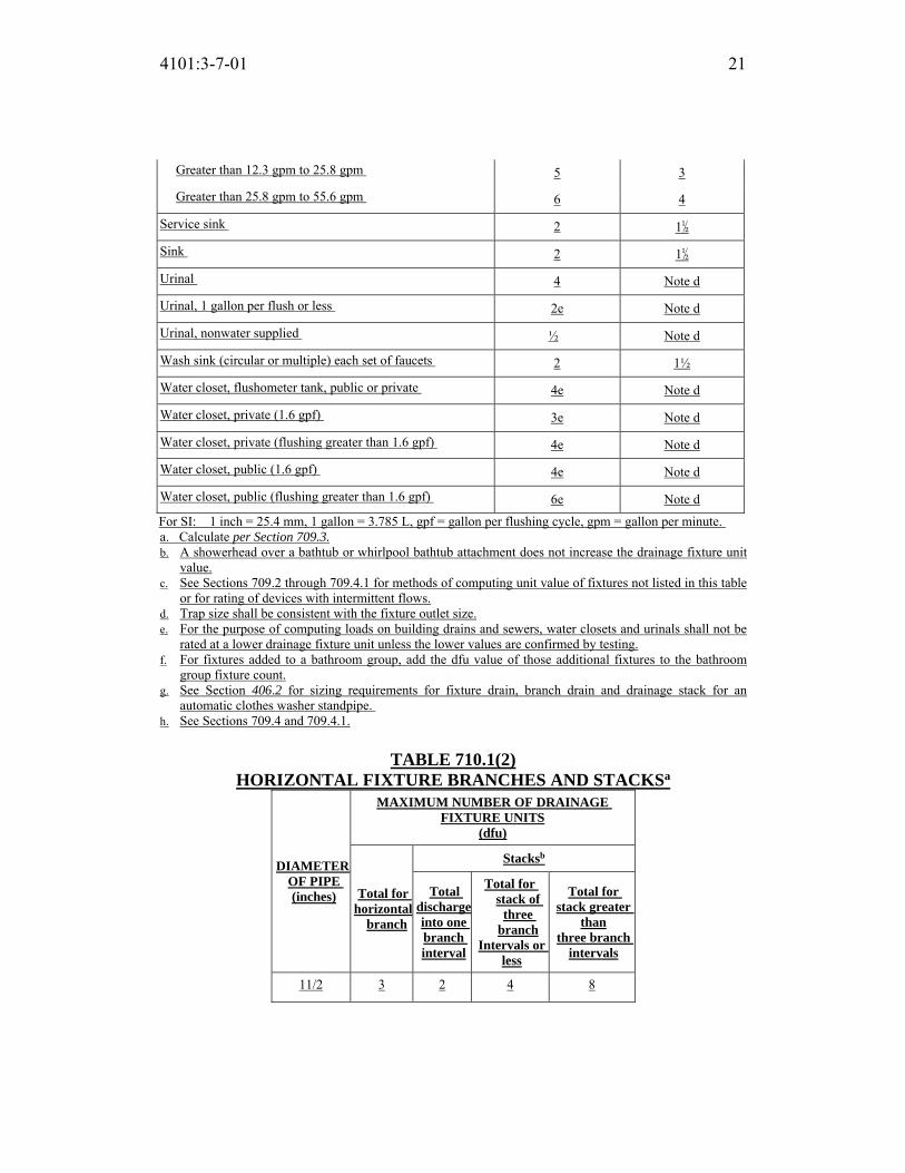
4101:3-7-01 21
Greater than 12.3 gpm to 25.8 gpm 5 3
Greater than 25.8 gpm to 55.6 gpm 6 4
Service sink 2 1½
Sink 2 1½
Urinal 4 Note d
Urinal, 1 gallon per flush or less 2e Note d
Urinal, nonwater supplied ½ Note d
Wash sink (circular or multiple) each set of faucets 2 1½
Water closet, flushometer tank, public or private 4e Note d
Water closet, private (1.6 gpf) 3e Note d
Water closet, private (flushing greater than 1.6 gpf) 4e Note d
Water closet, public (1.6 gpf) 4e Note d
Water closet, public (flushing greater than 1.6 gpf) 6e Note d
For SI: 1 inch = 25.4 mm, 1 gallon = 3.785 L, gpf = gallon per flushing cycle, gpm = gallon per minute.
a. Calculate per Section 709.3. b. A showerhead over a bathtub or whirlpool bathtub attachment does not increase the drainage fixture unit
value.
c. See Sections 709.2 through 709.4.1 for methods of computing unit value of fixtures not listed in this table
or for rating of devices with intermittent flows.
d. Trap size shall be consistent with the fixture outlet size.
e. For the purpose of computing loads on building drains and sewers, water closets and urinals shall not be
rated at a lower drainage fixture unit unless the lower values are confirmed by testing.
f. For fixtures added to a bathroom group, add the dfu value of those additional fixtures to the bathroom
group fixture count.
g. See Section 406.2 for sizing requirements for fixture drain, branch drain and drainage stack for an
automatic clothes washer standpipe.
h. See Sections 709.4 and 709.4.1.
TABLE 710.1(2)
HORIZONTAL FIXTURE BR ANCHES AND STACKSa
DIAMETER OF PIPE (inches)
MAXIMUM NUMBER OF DRAINAGE FIXTURE UNITS
(dfu)
Total for horizontal
branch
Stacksb
Total discharge into one branch interval
Total for stack of three
branch
Intervals or less
Total for stack greater
than
three branch intervals
11/2 3 2 4 8

4101:3-7-01 22
2 6 6 10 24
21/2 12 9 20 42
3 20 20 48 72
4 160 90 240 500
5 360 200 540 1,100
6 620 350 960 1,900
8 1,400 600 2,200 3,600
10 2,500 1,000 3,800 5,600
12 3,900 1,500 6,000 8,400
15 7,000 Note c Note c Note c
For SI: 1 inch = 25.4 mm.
a. Does not include branches of the building drain. Refer to Table
710.1(1).
b. Stacks shall be sized based on the total accumulated connected
load at each story or branch interval. As the total accumulated
connected load decreases, stacks are permitted to be reduced in
size. Stack diameters shall not be reduced to less than one-half
of the diameter of the largest stack size required.
c. Sizing load based on design criteria.
710.1.1 Horizontal stack offsets. Horizontal stack offsets shall be sized as
required for building drains in accordance with Table 710.1(1), except as
required by Section 711.3.
710.1.2 Vertical stack offsets. Vertical stack offsets shall be sized as required
for straight stacks in accordance with Table 710.1(2), except where required
to be sized as a building drain in accordance with Section 711.1.1.
710.2 Future fixtures. Where provision is made for the future installation of
fixtures, those provided for shall be considered in determining the required sizes
of drain pipes.
SECTION 711
OFFSETS IN DRAINAGE PIPING IN BUILDINGS OF FIVE STORIES OR MORE
711.1 Horizontal branch connections above or below vertical stack offsets. If a horizontal branch connects to the stack within 2 feet (610 mm) above or below a
vertical stack offset, and the offset is located more than four branch intervals

4101:3-7-01 23
below the top of the stack, the offset shall be vented in accordance with Section
906.
711.1.1 Omission of vents for vertical stack offsets. Vents for vertical
offsets required by Section 711.1 shall not be required where the stack and its
offset are sized as a building drain [see Table 710.1(1)].
711.2 Horizontal stack offsets. A stack with a horizontal offset located more
than four branch intervals below the top of the stack shall be vented in accordance
with Section 907 and sized as follows:
1. The portion of the stack above the offset shall be sized as for a vertical
stack based on the total number of drainage fixture units above the offset.
2. The offset shall be sized in accordance with Section710.1.1.
3. The portion of the stack below the offset shall be sized as for the offset or
based on the total number of drainage fixture units on the entire stack,
whichever is larger [see Table 710.1(2), Column 5].
711.2.1 Omission of vents for horizontal stack offsets. Vents for horizontal
stack offsets required by Section 711.2 shall not be required where the stack
and its offset are one pipe size larger than required for a building drain [see
Table 710.1(1)] and the entire stack and offset are not less in cross-sectional
area than that required for a straight stack plus the area of an offset vent as
provided for in Section 907.
711.3 Offsets below lowest branch. Where a vertical offset occurs in a soil or
waste stack below the lowest horizontal branch, a change in diameter of the stack
because of the offset shall not be required. If a horizontal offset occurs in a soil or
waste stack below the lowest horizontal branch, the required diameter of the
offset and the stack below it shall be determined as for a building drain in
accordance with Table 710.1(1).
SECTION 712
SUMPS AND EJECTORS
712.1 Building subdrains. Building subdrains that cannot be discharged to the
sewer by gravity flow shall be discharged into a tightly covered and vented sump
from which the liquid shall be lifted and discharged into the building gravity
drainage system by automatic pumping equipment or other approved method. In
other than existing structures, the sump shall not receive drainage from any piping
within the building capable of being discharged by gravity to the building sewer.

4101:3-7-01 24
712.2 Valves required. A check valve and a full open valve located on the
discharge side of the check valve shall be installed in the pump or ejector
discharge piping between the pump or ejector and the gravity drainage system.
Access shall be provided to such valves. Such valves shall be located above the
sump cover required by Section 712.1 or, where the discharge pipe from the
ejector is below grade, the valves shall be accessibly located outside the sump
below grade in an access pit with a removable access cover.
Exception: In buildings where the “Residential Code of Ohio” applies, only a check valve shall be required, located on the discharge piping from the sewage pump or ejector.
712.3 Sump design. The sump pump, pit and discharge piping shall conform to
the requirements of Sections 712.3.1 through 712.3.5.
712.3.1 Sump pump. The sump pump capacity and head shall be
appropriate to anticipated use requirements.
712.3.2 Sump pit. The sump pit shall be not less than 18 inches (457 mm) in
diameter and not less than 24 inches (610 mm) in depth, unless otherwise
approved. The pit shall be accessible and located such that all drainage flows
into the pit by gravity. The sump pit shall be constructed of tile, concrete,
steel, plastic or other approved materials. The pit bottom shall be solid and
provide permanent support for the pump. The sump pit shall be fitted with a
gastight removable cover that is installed flush with grade or floor level, or
above grade or floor level. The cover shall be adequate to support anticipated
loads in the area of use. The sump pit shall be vented in accordance with
Chapter 9.
712.3.3 Discharge pipe and fittings. Discharge pipe and fittings serving
sump pumps and ejectors shall be constructed of materials in accordance with
Sections 712.3.3.1 and 712.3.3.2 and shall be approved.
712.3.3.1 Materials. Pipe and fitting materials shall be constructed of
brass, copper, CPVC, ductile iron, PE, or PVC.
712.3.3.2 Ratings. Pipe and fittings shall be rated for the maximum
system operating pressure and temperature. Pipe fitting materials shall be
compatible with the pipe material. Where pipe and fittings are buried in
the earth, they shall be suitable for burial.
712.3.4 Maximum effluent level. The effluent level control shall be adjusted
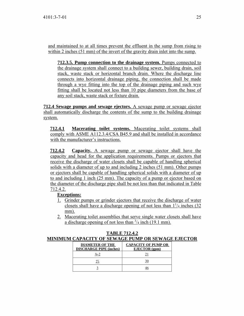
4101:3-7-01 25
and maintained to at all times prevent the effluent in the sump from rising to
within 2 inches (51 mm) of the invert of the gravity drain inlet into the sump.
712.3.5. Pump connection to the drainage system. Pumps connected to
the drainage system shall connect to a building sewer, building drain, soil
stack, waste stack or horizontal branch drain. Where the discharge line
connects into horizontal drainage piping, the connection shall be made
through a wye fitting into the top of the drainage piping and such wye
fitting shall be located not less than 10 pipe diameters from the base of
any soil stack, waste stack or fixture drain.
712.4 Sewage pumps and sewage ejectors. A sewage pump or sewage ejector
shall automatically discharge the contents of the sump to the building drainage
system.
712.4.1 Macerating toilet systems. Macerating toilet systems shall
comply with ASME A112.3.4/CSA B45.9 and shall be installed in accordance
with the manufacturer’s instructions.
712.4.2 Capacity. A sewage pump or sewage ejector shall have the
capacity and head for the application requirements. Pumps or ejectors that
receive the discharge of water closets shall be capable of handling spherical
solids with a diameter of up to and including 2 inches (51 mm). Other pumps
or ejectors shall be capable of handling spherical solids with a diameter of up
to and including 1 inch (25 mm). The capacity of a pump or ejector based on
the diameter of the discharge pipe shall be not less than that indicated in Table
712.4.2.
Exceptions: 1. Grinder pumps or grinder ejectors that receive the discharge of water
closets shall have a discharge opening of not less than 11/4 inches (32
mm).
2. Macerating toilet assemblies that serve single water closets shall have
a discharge opening of not less than 3/4 inch (19.1 mm).
TABLE 712.4.2
MINIMUM CAPACITY OF SEWAGE PUMP OR SEWAGE EJECTOR
DIAMETER OF THE DISCHARGE PIPE (inches)
CAPACITY OF PUMP OR EJECTOR (gpm)
¾-2 21
2½ 30
3 46

4101:3-7-01 26
For SI: 1 inch = 25.4 mm, 1 gallon per minute = 3.785 L/m.
SECTION 713
HEALTH CARE PLUMBING
713.1 Scope. This section shall govern those aspects of health care plumbing
systems that differ from plumbing systems in other structures. Health care
plumbing systems shall conform to this section in addition to the other
requirements of this code. The provisions of this section shall apply to the special
devices and equipment installed and maintained in the following occupancies:
nursing homes; homes for the aged; orphanages; infirmaries; first aid stations;
psychiatric facilities; clinics; professional offices of dentists and doctors;
mortuaries; educational facilities; surgery, dentistry, research and testing
laboratories; establishments manufacturing pharmaceutical drugs and medicines;
and other structures with similar apparatus and equipment classified as plumbing.
713.2 Bedpan washers and clinical sinks. Bedpan washers and clinical sinks
shall connect to the drainage and vent system in accordance with the requirements
for a water closet. Bedpan washers shall also connect to a local vent.
713.3 Indirect waste. Sterilizers, steamers and condensers shall discharge to the
drainage through an indirect waste pipe by means of an air gap. Where a battery
of not more than three sterilizers discharges to an individual receptor, the distance
between the receptor and a sterilizer shall not exceed 8 feet (2438 mm). The
indirect waste pipe on a bedpan steamer shall be trapped.
713.4 Vacuum system station. Ready access shall be provided to vacuum
system station receptacles. Such receptacles shall be built into cabinets or
recesses and shall be visible.
713.5 Bottle system. Vacuum (fluid suction) systems intended for collecting,
removing and disposing of blood, pus or other fluids by the bottle system shall be
provided with receptacles equipped with an overflow prevention device at each
vacuum outlet station.
713.6 Central disposal system equipment. Central vacuum (fluid suction)
systems shall provide continuous service. Systems equipped with collecting or
control tanks shall provide for draining and cleaning of the tanks while the system
is in operation. In hospitals, the system shall be connected to the emergency
power system. The exhausts from a vacuum pump serving a vacuum (fluid
suction) system shall discharge separately to open air above the roof.

4101:3-7-01 27
713.7 Central vacuum or disposal systems. Where the waste from a central
vacuum (fluid suction) system of the barometric-lag, collection-tank or bottle-
disposal type is connected to the drainage system, the waste shall be directly
connected to the sanitary drainage system through a trapped waste.
713.7.1 Piping. The piping of a central vacuum (fluid suction) system shall
be of corrosion-resistant material with a smooth interior surface. A branch
shall be not less than 1/2inch (12.7 mm) nominal pipe size for one outlet and
shall be sized in accordance with the number of vacuum outlets. A main shall
be not less than 1-inch (25 mm) nominal pipe size. The pipe sizing shall be
increased in accordance with the manufacturer’s instructions as stations are
increased.
713.7.2 Velocity. The velocity of airflow in a central vacuum (fluid
suction) system shall be less than 5,000 feet per minute (25 m/s).
713.8 Vent connections prohibited. Connections between local vents serving
bedpan washers or sterilizer vents serving sterilizing apparatus and normal
sanitary plumbing systems are prohibited. Only one type of apparatus shall be
served by a local vent.
713.9 Local vents and stacks for bedpan washers. Bedpan washers shall be
vented to open air above the roof by means of one or more local vents. The local
vent for a bedpan washer shall be not less than a 2-inch-diameter (51 mm) pipe. A
local vent serving a single bedpan washer is permitted to drain to the fixture
served.
713.9.1 Multiple installations. Where bedpan washers are located above
each other on more than one floor, a local vent stack is permitted to be
installed to receive the local vent on the various floors. Not more than three
bedpan washers shall be connected to a 2-inch (51 mm) local vent stack, not
more than six to a 3-inch (76 mm) local vent stack and not more than 12 to a
4-inch (102 mm) local vent stack. In multiple installations, the connections
between a bedpan washer local vent and a local vent stack shall be made with
tee or tee-wye sanitary pattern drainage fittings installed in an upright
position.
713.9.2 Trap required. The bottom of the local vent stack, except where
serving only one bedpan washer, shall be drained by means of a trapped and
vented waste connection to the sanitary drainage system. The trap and waste
shall be the same size as the local vent stack.

4101:3-7-01 28
713.9.3 Trap seal maintenance. A water supply pipe not less than 1/4 inch
(6.4 mm) in diameter shall be taken from the flush supply of each bedpan
washer on the discharge or fixture side of the vacuum breaker, shall be
trapped to form not less than a 3-inch (76 mm) water seal and shall be
connected to the local vent stack on each floor. The water supply shall be
installed so as to provide a supply of water to the local vent stack for
cleansing and drain trap seal maintenance each time a bedpan washer is
flushed.
713.10 Sterilizer vents and stacks. Multiple installations of pressure and
nonpressure sterilizers shall have the vent connections to the sterilizer vent stack
made by means of inverted wye fittings. Access shall be provided to vent
connections for the purpose of inspection and maintenance.
713.10.1 Drainage. The connection between sterilizer vent or exhaust
openings and the sterilizer vent stack shall be designed and installed to drain
to the funnel or basket type waste fitting. In multiple installations, the
sterilizer vent stack shall be drained separately to the lowest sterilizer funnel
or basket-type waste fitting or receptor.
713.11 Sterilizer vent stack sizes. Sterilizer vent stack sizes shall comply with
Sections 713.11.1 through 713.11.4.
713.11.1 Bedpan steamers. The minimum size of a sterilizer vent serving a
bedpan steamer shall be 11/2 inches (38 mm) in diameter. Multiple
installations shall be sized in accordance with Table 713.11.1.
TABLE 713.11.1 STACK SIZES FOR BEDPAN STEAMERS AND BOILING-TYPE
STERILIZERS (Number of Connections of Various Sizes Permitted to Various-sized Sterilizer Vent Stacks)
STACK SIZE
(inches)
CONNECTION SIZE
1½" 2"
1½a 1 or 0
2a 2 or 1
2b 1 and 1
3a 4 or 2
3b 2 and 2

4101:3-7-01 29
4a 8 or 4
4b 4 and 4
For SI: 1 inch = 25.4 mm.
a. Total of each size.
b. Combination of sizes.
713.11.2 Boiling-type sterilizers. The size of a sterilizer vent stack shall be
not less than 2 inches (51 mm) in diameter where serving a utensil sterilizer
and not less than 11/2 inches (38 mm) in diameter where serving an instrument
sterilizer. Combinations of boiling-type sterilizer vent connections shall be
sized in accordance with Table 713.11.1.
713.11.3 Pressure sterilizers. Pressure sterilizer vent stacks shall be 21/2
inches (64 mm) minimum. Those serving combinations of pressure sterilizer
exhaust connections shall be sized in accordance with Table 713.11.3.
713.11.4 Pressure instrument washer sterilizer sizes. The diameter of a
sterilizer vent stack serving an instrument washer sterilizer shall be not less
than 2 inches (51 mm). Not more than two sterilizers shall be installed on a 2-
inch (51 mm) stack, and not more than four sterilizers shall be installed on a
3-inch (76 mm) stack.
TABLE 713.11.3 STACK SIZES FOR PRESSURE STERILIZERS (Number of Connections of Various Sizes Permitted To Various-sized Vent
Stacks) STACK
SIZE
(inches)
CONNECTION SIZE
¾” 1" 1¼" 1½"
1½a 3 or 2 or 1 —
1½b 2 and 1 — —
2a 6 or 3 or 2 or 1
2b 3 and 2 — —
2b 2 and 1 and 1 —
2b 1 and 1 and — 1
3a 15 or 7 or 5 or 3
3b 1 and 1 and
5 and 2 and 2
1
For SI: 1 inch = 25.4 mm.
a. Total of each size.
b. Combination of sizes.

4101:3-7-01 30
SECTION 714 COMPUTERIZED DRAINAGE DESIGN
714.1 Design of drainage system. The sizing, design and layout of the drainage
system shall be permitted to be designed by approved computer design methods.
714.2 Load on drainage system. The load shall be computed from the
simultaneous or sequential discharge conditions from fixtures, appurtenances and
appliances or the peak usage design condition.
714.2.1 Fixture discharge profiles. The discharge profiles for flow rates
versus time from fixtures and appliances shall be in accordance with the
manufacturer’s specifications.
714.3 Selections of drainage pipe sizes. Pipe shall be sized to prevent full-bore
flow.
714.3.1 Selecting pipe wall roughness. Pipe size calculations shall be
conducted with the pipe wall roughness factor (ks), in accordance with the
manufacturer’s specifications and as modified for aging roughness factors
with deposits and corrosion.
714.3.2 Slope of horizontal drainage piping. Horizontal drainage piping
shall be designed and installed at slopes in accordance with Table 704.1.
SECTION 715
BACKWATER VALVES
715.1 Sewage backflow. If required by the “Ohio Environmental Protection Agency” or local sewer purveyor, a backwater valve shall be installed only for plumbing fixtures installed on a floor with a finished floor elevation below the
elevation of the manhole cover of the next upstream manhole in the public sewer.
Such fixtures shall be protected by a backwater valve installed in the building
drain, or horizontal branch serving such fixtures. Plumbing fixtures installed on a
floor with a finished floor elevation above the elevation of the manhole cover of
the next upstream manhole in the public sewer shall not discharge through a
backwater valve.
Exception: In existing buildings, fixtures above the elevation of the manhole
cover of the next upstream manhole in the public sewer shall not be prohibited
from discharging through a backwater valve.

4101:3-7-01 31
715.2 Material. Bearing parts of backwater valves shall be of corrosion-resistant
material. Backwater valves shall comply with ASME A112.14.1, CSA B181.1 or
CSA B181.2.
715.3 Seal. Backwater valves shall be so constructed as to provide a mechanical
seal against backflow.
715.4 Diameter. Backwater valves, when fully opened, shall have a capacity not
less than that of the pipes in which they are installed.
715.5 Location. Backwater valves shall be installed so that access is provided to
the working parts for service and repair.
SECTION 716
VACUUM DRAINAGE SYSTEMS
716.1 Scope. Vacuum drainage systems shall be in accordance with Sections
716.2 through 716.4.
716.2 System design. Vacuum drainage systems shall be designed in accordance
with the vacuum drainage system manufacturer’s instructions. The system layout,
including piping layout, tank assemblies, vacuum pump assembly and other
components necessary for proper function of the system shall be in accordance
with the manufacturer’s instructions. Plans, specifications and other data for such
systems shall be submitted to the code official for review and approval prior to
installation.
716.2.1 Fixtures. Gravity-type fixtures installed in vacuum drainage systems
shall comply with Chapter 4.
716.2.2 Drainage fixture units. Drainage fixture units for gravity drainage
systems that discharge into, or receive discharge from, vacuum drainage
systems shall be based on the values in this chapter.
716.2.3 Water supply fixture units. Water supply fixture units shall be based
on the values in Chapter 6 of this code, except that the water supply fixture
unit for a vacuum-type water closet shall be 1.
716.2.4 Traps and cleanouts. Gravity drainage fixtures shall be provided
with traps and cleanouts in accordance with this chapter and Chapter 10.

4101:3-7-01 32
716.2.5 Materials. Vacuum drainage pipe, fitting and valve materials shall be
in accordance with the vacuum drainage system manufacturer’s instructions
and the requirements of this chapter.
716.3 Testing and demonstrations. After completion of the entire system
installation, the system shall be subjected to a vacuum test of 19 inches (483 mm)
of mercury and shall be operated to function as required by the code official and
the manufacturer of the vacuum drainage system. Recorded proof of all tests shall
be submitted to the code official.
716.4 Written instructions. Written instructions for the operation, maintenance,
safety and emergency procedures shall be provided to the building owner. The
code official shall verify that the building owner is in receipt of such instructions.
SECTION 717
REPLACEMENT OF UNDERGROUND SEWERS BY PIPE-BURSTING METHODS
717.1 General. Deleted.
717.2 Applicability. Deleted.
717.3 Pre-installation inspection. Deleted.
717.4 Pipe. Deleted.
717.5 Pipe fittings. Deleted.
717.6 Cleanouts. Deleted.
717.7 Post-installation inspection. Deleted.
717.8 Pressure testing. Deleted.

Replaces: 4101:3-7-01
Effective: 11/01/2017
Five Year Review (FYR) Dates: 11/01/2022
CERTIFIED ELECTRONICALLY
Certification
05/26/2017
Date
Promulgated Under: 119.03Statutory Authority: 3781.10(A), 4104.43(A)(1)Rule Amplifies: 3781.03(D), 3781.10, 3781.11, 3791.04Prior Effective Dates: 3/1/98, 10/1/99, 7/15/00, 1/1/02, 3/1/06, 7/1/07,
11/1/11
4101:3-7-01 33

4101:3-8-01 Indirect/special waste.
[Comment: When a reference is made within this rule to a federal statutory provision, an industry consensus standard, or any other technical publication, the specific date and title of the publication as well as the name and address of the promulgating agency are listed in rule 4101:3-15-01 of the Administrative Code. The application of the referenced standards shall be limited and as prescribed in section 102.5 of rule 4101:1-1-01 of the Administrative Code.]
SECTION 801 GENERAL
801.1 Scope. This chapter shall govern matters concerning indirect waste piping and special wastes. This chapter shall further control matters concerning food-handling establishments, sterilizers, clear-water waste, swimming pools, methods of providing air breaks or air gaps, and neutralizing devices for corrosive wastes. 801.2 Protection. Devices, appurtenances, appliances and apparatus intended to serve some special function, such as sterilization, distillation, processing, cooling, or storage of ice or foods, and that discharge to the drainage system, shall be provided with protection against backflow, flooding, fouling, contamination and stoppage of the drain.
SECTION 802 INDIRECT WASTES
802.1 Where required. Food-handling equipment, in other than dwelling units, clear-water waste, dishwashing machines and utensils, pots, pans and dishwashing sinks shall discharge through an indirect waste pipe as specified in Sections 802.1.1 through 802.1.8. Health-care related fixtures, devices and equipment shall discharge to the drainage system through an indirect waste pipe by means of an air gap in accordance with this chapter and Section 713.3. Fixtures not required by this section to be indirectly connected shall be directly connected to the plumbing system in accordance with Chapter 7.
Exception: Approved health care related fixtures, devices, and equipment may be directly connected to the drainage system if required to be directly connected in accordance with the manufacturer’s installation instructions.
802.1.1 Food handling. Equipment and fixtures utilized for the storage, preparation and handling of food shall discharge through an indirect waste pipe by means of an air gap. Each well of a multiple-compartment sink shall
ACTION: Final DATE: 05/26/2017 2:37 PM
RB p(170947) pa(315228) d(672535) ra(523777) print date: 06/01/2017 8:34 AM
4101:3-8-01 2
discharge independently to a waste receptor. 802.1.2 Floor drains in food storage areas. Floor drains located within walk-in refrigerators or freezers in food service and food establishments shall be indirectly connected to the sanitary drainage system by means of an air gap. Where a floor drain is located within an area subject to freezing, the waste line serving the floor drain shall not be trapped and shall indirectly discharge into a waste receptor located outside of the area subject to freezing.
Exception: Where protected against backflow by a backwater valve, such floor drains shall be indirectly connected to the sanitary drainage system by means of an air break or an air gap.
802.1.3 Potable clear-water waste. Where devices and equipment, such as sterilizers and relief valves, discharge potable water to the building drainage system, the discharge shall be through an indirect waste pipe by means of an air gap. 802.1.4 Swimming pools. Where waste water from swimming pools, backwash from filters and water from pool deck drains discharge to the building drainage system, the discharge shall be through an indirect waste pipe by means of an air gap. 802.1.5 Nonpotable clear-water waste. Where devices and equipment such as process tanks, filters, drips and boilers discharge nonpotable water to the building drainage system, the discharge shall be through an indirect waste pipe by means of an air break or an air gap. 802.1.6 Domestic dishwashing machines. Domestic dishwashing machines shall discharge indirectly through an air gap or air break into a waste receptor in accordance with Section 802.2, or discharge into a wye branch fitting on the tailpiece of the kitchen sink or the dishwasher connection of a food waste disposer. The waste line of a domestic dishwashing machine discharging into a kitchen sink tailpiece or food waste disposer shall connect to a deck-mounted air gap or the waste line shall rise and be securely fastened to the underside of the sink rim or counter. 802.1.7 Commercial dishwashing machines. The discharge from a commercial dishwashing machine shall be through an air gap or air break into a waste receptor in accordance with Section 802.2. 802.1.8 Food utensils, dishes, pots and pans sinks. Sinks, in other than

4101:3-8-01 3
dwelling units, used for the washing, rinsing or sanitizing of utensils, dishes, pots, pans or service ware used in the preparation, serving or eating of food shall discharge indirectly through an air gap or an air break to the drainage system.
802.2 Installation. Indirect waste piping shall discharge through an air gap or air break into a waste receptor. Waste receptors shall be trapped and vented and shall connect to the building drainage system. Indirect waste piping that exceeds 30 inches (762 mm) in developed length measured horizontally, or 54 inches (1372 mm) in total developed length, shall be trapped.
Exception: Where a waste receptor receives only clear water waste and does not directly connect to a sanitary drainage system, the receptor shall not require a trap.
802.2.1 Air gap. The air gap between the indirect waste pipe and the flood level rim of the waste receptor shall be not less than twice the effective opening of the indirect waste pipe. 802.2.2 Air break. An air break shall be provided between the indirect waste pipe and the trap seal of the waste receptor.
802.3 Waste receptors. For other than hub drains that receive only clear-water waste and standpipes, a removable strainer or basket shall be installed in waste receptors. Waste receptors shall not be installed in concealed spaces. Waste receptors shall not be installed in plenums, crawl spaces, attics, interstitial spaces above ceilings and below floors. Ready access shall be provided to waste receptors.
802.3.1 Size of receptors. A waste receptor shall be sized for the maximum discharge of all indirect waste pipes served by the receptor. Receptors shall be installed to prevent splashing or flooding. 802.3.2 Hub drains. A hub drain shall be in the form of a hub or a pipe extending not less than 1 inch (25 mm) above a water-impervious floor. 802.3.3 Standpipes. Standpipes shall be individually trapped. Standpipes shall extend not less than 18 inches (457 mm) but not greater than 42 inches (1066 mm) above the trap weir. Access shall be provided to standpipes and drains for rodding.
SECTION 803

4101:3-8-01 4
SPECIAL WASTES 803.1 Neutralizing device required for corrosive wastes. Corrosive liquids, spent acids or other harmful chemicals that destroy or injure a drain, sewer, soil or waste pipe, or create noxious or toxic fumes or interfere with sewage treatment processes shall not be discharged into the plumbing system without being thoroughly diluted, neutralized or treated by passing through an approved dilution or neutralizing device. Such devices shall be automatically provided with a sufficient supply of diluting water or neutralizing medium so as to make the contents non injurious before discharge into the drainage system. The nature of the corrosive or harmful waste and the method of its treatment or dilution shall be approved prior to installation. 803.2 System design. A chemical drainage and vent system shall be designed and installed in accordance with this code. Chemical drainage and vent systems shall be completely separated from the sanitary systems. Chemical waste shall not discharge to a sanitary drainage system until such waste has been treated in accordance with Section 803.1.
SECTION 804 MATERIALS, JOINTS AND CONNECTIONS
804.1 General. The materials and methods utilized for the construction and installation of indirect waste pipes and systems shall comply with the applicable provisions of Chapter 7.

Replaces: 4101:3-8-01
Effective: 11/01/2017
Five Year Review (FYR) Dates: 11/01/2022
CERTIFIED ELECTRONICALLY
Certification
05/26/2017
Date
Promulgated Under: 119.03Statutory Authority: 3781.10(A), 4104.43(A)(1)Rule Amplifies: 3781.10, 3781.11, 3791.04Prior Effective Dates: 3/1/98, 1/1/02, 3/1/05, 9/6/05, 7/1/07, 11/1/11
4101:3-8-01 5

4101:3-9-01 Vents.
[Comment: When a reference is made within this rule to a federal statutory provision, an industry consensus standard, or any other technical publication, the specific date and title of the publication as well as the name and address of the promulgating agency are listed in rule 4101:3-15-01 of the Administrative Code. The application of the referenced standards shall be limited and as prescribed in section 102.5 of rule 4101:1-1-01 of the Administrative Code.]
SECTION 901 GENERAL
901.1 Scope. The provisions of this chapter shall govern the materials, design,
construction and installation of vent systems.
901.2 Trap seal protection. The plumbing system shall be provided with a
system of vent piping that will permit the admission or emission of air so that the
seal of any fixture trap shall not be subjected to a pressure differential of more
than 1 inch of water column (249 Pa).
901.2.1 Venting required. Traps and trapped fixtures shall be vented in
accordance with one of the venting methods specified in this chapter.
901.3 Chemical waste vent systems. The vent system for a chemical waste
system shall be independent of the sanitary vent system and shall terminate
separately through the roof to the outdoors or to an air admittance valve that
complies with ASSE 1049. Air admittance valves for chemical waste systems
shall comply with Section 918.8 and shall be constructed of materials approved in
accordance with Section 702.5 and shall be tested for chemical resistance in
accordance with ASTM F 1412.
901.4 Use limitations. The plumbing vent system shall not be utilized for
purposes other than the venting of the plumbing system.
901.5 Tests. The vent system shall be tested in accordance with Section 312.
901.6 Engineered systems. Engineered venting systems shall conform to the
provisions of Section 919.
SECTION 902 MATERIALS
ACTION: Final DATE: 05/26/2017 2:37 PM
RB p(170947) pa(315228) d(672538) ra(523776) print date: 06/01/2017 8:35 AM

4101:3-9-01 2
902.1 Vents. The materials and methods utilized for the construction and
installation of venting systems shall comply with the applicable provisions of
Section 702.
902.2 Sheet copper. Sheet copper for vent pipe flashings shall conform to ASTM
B 152 and shall weigh not less than 8 ounces per square foot (2.5 kg/m2).
902.3 Sheet lead. Sheet lead for vent pipe flashings shall weigh not less than 3
pounds per square foot (15 kg/m2) for field-constructed flashings and not less
than 21/2 pounds per square foot (12 kg/m2) for prefabricated flashings.
SECTION 903
VENT TERMINALS
903.1 Roof extension. Open vent pipes that extend through a roof shall be
terminated not less than 12 inches (304.8 mm) above the roof. Where a roof is to
be used for assembly or as a promenade, observation deck, sunbathing deck or
similar purposes, open vent pipes shall terminate not less than 7 feet (2134 mm)
above the roof within 10 feet of the occupiable area.
903.2 Frost closure. Where the 97.5-percent value for outside design temperature
is 0°F (-18°C) or less, vent extensions through a roof or wall shall be not less than
3 inches (76 mm) in diameter. Any increase in the size of the vent shall be made
not less than 1 foot (305 mm) inside the thermal envelope of the building.
903.3 Flashings. The juncture of each vent pipe with the roof line shall be made
water tight by an approved flashing.
903.4 Prohibited use. A vent terminal shall not be used for any purpose other
than a vent terminal.
903.5 Location of vent terminal. An open vent terminal from a drainage system
shall not be located directly beneath any door, openable window, or other air
intake opening of the building or of an adjacent building, and any such vent
terminal shall not be within 10 feet (3048 mm) horizontally of such an opening
unless it is 3 feet (914 mm) or more above the top of such opening.
903.6 Extension through the wall. Vent terminals extending through the wall
shall terminate at a point not less than 10 feet (3048 mm) from a lot line and not
less than 10 feet (3048 mm) above average ground level. Vent terminals shall not

4101:3-9-01 3
terminate under the overhang of a structure with soffit vents. Side wall vent
terminals shall be protected to prevent birds or rodents from entering or blocking
the vent opening.
903.7 Extension outside a structure. In climates where the 97.5-percent value
for outside design temperature is less than 0°F (-18°C), vent pipes installed on the
exterior of the structure shall be protected against freezing by insulation, heat or
both.
SECTION 904
OUTDOOR VENT EXTENSIONS
904.1 Required vent extension. The vent system serving each building drain
shall have not less than one vent pipe that extends to the outdoors.
904.1.1 Installation. The required vent shall be a dry vent that connects to the
building drain or an extension of a drain that connects to the building drain.
Such vent shall not be an island fixture vent as allowed by Section 916.
904.1.2 Size. The required vent shall be sized in accordance with Section
906.2 based on the required size of the building drain.
904.2 Vent stack required. A vent stack shall be required for every drainage
stack that has five branch intervals or more.
Exception: Drainage stacks installed in accordance with Section 913.
904.3 Vent termination. Vent stacks or stack vents shall terminate outdoors to
the open air or to a stack-type air admittance valve in accordance with Section
918.
904.4 Vent connection at base. Vent stacks shall connect to the base of the
drainage stack. The vent stack shall connect at or below the lowest horizontal
branch. Where the vent stack connects to the building drain, the connection shall
be located downstream of the drainage stack and within a distance of 10 times the
diameter of the drainage stack.
904.5 Vent headers. Stack vents and vent stacks connected into a common vent
header at the top of the stacks and extending to the open air at one point shall be
sized in accordance with the requirements of Section 906.1. The number of
fixture units shall be the sum of all fixture units on all stacks connected thereto,
and the developed length shall be the longest vent length from the intersection at

4101:3-9-01 4
the base of the most distant stack to the vent terminal in the open air, as a direct
extension of one stack.
SECTION 905
VENT CONNECTIONS AND GRADES
905.1 Connection. Individual, branch and circuit vents shall connect to a vent
stack, stack vent, air admittance valve or extend to the open air.
905.2 Grade. Vent and branch vent pipes shall be so graded and connected as to
drain back to the drainage pipe by gravity.
905.3 Vent connection to drainage system. Every dry vent connecting to a
horizontal drain shall connect above the centerline of the horizontal drain pipe.
905.4 Vertical rise of vent. Every dry vent shall rise vertically to a point not less
than 6 inches (152 mm) above the flood level rim of the highest trap or trapped
fixture being vented.
Exception: Vents for interceptors located outdoors.
905.5 Height above fixtures. A connection between a vent pipe and a vent stack
or stack vent shall be made at not less than 6 inches (152 mm) above the flood
level rim of the highest fixture served by the vent. Horizontal vent pipes forming
branch vents, relief vents or loop vents shall be located not less than 6 inches (152
mm) above the flood level rim of the highest fixture served.
905.6 Vent for future fixtures. Where the drainage piping has been roughed-in
for future fixtures, a rough-in connection for a vent shall be installed. The vent
size shall be not less than one-half the diameter of the rough-in drain to be served.
The vent rough-in shall connect to the vent system, or shall be vented by other
means as provided for in this chapter. The connection shall be identified to
indicate that it is a vent.
SECTION 906
VENT PIPE SIZING
906.1 Size of stack vents and vent stacks. The minimum required diameter of
stack vents and vent stacks shall be determined from the developed length and the
total of drainage fixture units connected thereto in accordance with Table 906.1,
but in no case shall the diameter be less than one-half the diameter of the drain
served or less than 11/4 inches (32 mm).

4101:3-9-01 5
906.2 Vents other than stack vents or vent stacks. The diameter of individual
vents, branch vents, circuit vents and relief vents shall be not less than one-half
the required diameter of the drain served. The required size of the drain shall be
determined in accordance with Table 710.1(2). Vent pipes shall not be less than
11/4 inches (32 mm) in diameter. Vents exceeding 40 feet (12 192 mm) in
developed length shall be increased by one nominal pipe size for the entire
developed length of the vent pipe. Relief vents for soil and waste stacks in
buildings having more than 10 branch intervals shall be sized in accordance with
Section 908.2.
906.3 Developed length. The developed length of individual, branch, circuit and
relief vents shall be measured from the farthest point of vent connection to the
drainage system to the point of connection to the vent stack, stack vent or
termination outside of the building.
906.4 Multiple branch vents. Where multiple branch vents are connected to a
common branch vent, the common branch vent shall be sized in accordance with
this section based on the size of the common horizontal drainage branch that is or
would be required to serve the total drainage fixture unit load being vented.
906.5 Sump vents. Sump vent sizes shall be determined in accordance with
Sections 906.5.1 and 906.5.2.
906.5.1 Sewage pumps and sewage ejectors other than pneumatic. Drainage piping below the building sewer level shall be vented in the same
manner as that of a gravity system. Building sump vent sizes for sumps with
sewage pumps or sewage ejectors, other than pneumatic, shall be determined
in accordance with Table 906.5.1.
906.5.2 Pneumatic sewage ejectors. The air pressure relief pipe from a
pneumatic sewage ejector shall be connected to an independent vent stack terminating as required for vent extensions through the roof. The relief pipe
shall be sized to relieve air pressure inside the ejector to atmospheric pressure,
but shall be not less than 11/4 inches (32 mm) in size.
SECTION 907
VENTS FOR STACK OFFSETS
907.1 Vent for horizontal offset of drainage stack. Horizontal offsets of
drainage stacks shall be vented where five or more branch intervals are located

4101:3-9-01 6
above the offset. The offset shall be vented by venting the upper section of the
drainage stack and the lower section of the drainage stack.
907.2 Upper section. The upper section of the drainage stack shall be vented as a
separate stack with a vent stack connection installed in accordance with Section
904.4. The offset shall be considered the base of the stack.
TABLE 906.1
SIZE AND DEVELOPED LENGTH OF STACK VENTS AND VENT STACKS
DIAMETER OF SOIL OR WASTE STACK
(inches)
TOTAL FIXTURE UNITS BEING VENTED (dfu)
MAXIMUM DEVELOPED LENGTH OF VENT (feet)a DIAMETER OF VENT (inches)
1¼ 1½ 2 2½ 3 4 5 6 8 10 12
1¼
1½
1½
2
8
10
30
50
30 150
100
— — — — — — — — —
2
2
2½
12
20
42 30
26
75
50
30
200
150
100300
— — — — — — —
3
3
3
10
21
53 —
42
32
27
150
110
94
360
270
230
1,040
810
680 — — — — — —
3
4
4
102
43
140 — 25
86
35
27
210
85
65
620
250
200 980
750
— — — — —
4
4
5
320
540
190 — —
23
21
55
50
28
170
150
82
640
580
320990
— — — —
5
5
5
490
940
1,400 — — —
21
18
16
63
53
49
250
210
190
760
670
590— — — —
6
6
6
500
1,100
2,000 — — — —
33
26
22
130
100
84
400
310
260
1,000
780
660 — — —
6
8
8
2,900
1,800
3,400 — — — —
20 77
31
24
240
95
73
600
240
190 940
729
— —
8
8
10
5,600
7,600
4,000 — — — — —
20
18
62
56
31
160
140
78
610
560
310 960
—
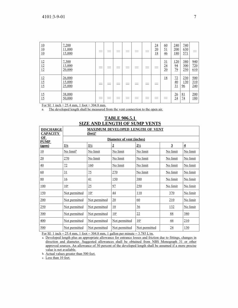
4101:3-9-01 7
10
10
10
7,200
11,000
15,000 — — — — — —
24
20
18
60
51
46
240
200
180
740
630
571 —
12
12
12
7,300
13,000
20,000 — — — — — — —
31
24
20
120
94
79
380
300
250
940
720
610
12
15
15
26,000
15,000
25,000 — — — — — — —
18 72
40
31
230
130
96
500
310
240
15
15
38,000
50,000 — — — — — — — — 26
24
81
74
200
180
For SI: 1 inch = 25.4 mm, 1 foot = 304.8 mm.
a. The developed length shall be measured from the vent connection to the open air.
TABLE 906.5.1 SIZE AND LENGTH OF SUMP VENTS
DISCHARGE CAPACITY OF PUMP (gpm)
MAXIMUM DEVELOPED LENGTH OF VENT (feet)a
Diameter of vent (inches)
1¼ 1½ 2 2½ 3 4
10 No limitb No limit No limit No limit No limit No limit
20 270 No limit No limit No limit No limit No limit
40 72 160 No limit No limit No limit No limit
60 31 75 270 No limit No limit No limit
80 16 41 150 380 No limit No limit
100 10c 25 97 250 No limit No limit
150 Not permitted 10c 44 110 370 No limit
200 Not permitted Not permitted 20 60 210 No limit
250 Not permitted Not permitted 10 36 132 No limit
300 Not permitted Not permitted 10c 22 88 380
400 Not permitted Not permitted Not permitted 10c 44 210
500 Not permitted Not permitted Not permitted Not permitted 24 130
For SI: 1 inch = 25.4 mm, 1 foot = 304.8 mm, 1 gallon per minute = 3.785 L/m.
a. Developed length plus an appropriate allowance for entrance losses and friction due to fittings, changes in
direction and diameter. Suggested allowances shall be obtained from NBS Monograph 31 or other
approved sources. An allowance of 50 percent of the developed length shall be assumed if a more precise
value is not available.
b. Actual values greater than 500 feet.
c. Less than 10 feet.

4101:3-9-01 8
907.3 Lower section. The lower section of the drainage stack shall be vented by a
yoke vent connecting between the offset and the next lower horizontal branch.
The yoke vent connection shall be permitted to be a vertical extension of the
drainage stack. The size of the yoke vent and connection shall be a minimum of
the size required for the vent stack of the drainage stack.
SECTION 908
RELIEF VENTS—STACKS OF MORE THAN 10 BRANCH INTERVALS
908.1 Where required. Soil and waste stacks in buildings having more than 10
branch intervals shall be provided with a relief vent at each tenth interval
installed, beginning with the top floor.
908.2 Size and connection. The size of the relief vent shall be equal to the size
of the vent stack to which it connects. The lower end of each relief vent shall
connect to the soil or waste stack through a wye below the horizontal branch
serving the floor, and the upper end shall connect to the vent stack through a wye
not less than 3 feet (914 mm) above the floor.
SECTION 909
FIXTURE VENTS
909.1 Distance of trap from vent. Each fixture trap shall have a protecting vent
located so that the slope and the developed length in the fixture drain from the
trap weir to the vent fitting are within the requirements set forth in Table 909.1.
Exception: The developed length of the fixture drain from the trap weir to the
vent fitting for self-siphoning fixtures, such as water closets, shall not be
limited.
TABLE 909.1
MAXIMUM DISTANCE OF FI XTURE TRAP FROM VENT SIZE OF TRAP (inches)
SLOPE (inch per foot)
DISTANCE FROM TRAP (feet)
1¼ ¼ 5
1½ ¼ 6
2 ¼ 8
3 ǩ 12
4 ǩ 16
For SI: 1 inch = 25.4 mm, 1 foot = 304.8 mm, 1 inch per foot = 83.3 mm/m.

4101:3-9-01 9
909.2 Venting of fixture drains. The total fall in a fixture drain due to pipe
slope shall not exceed the diameter of the fixture drain, nor shall the vent
connection to a fixture drain, except for water closets, be below the weir of the
trap.
909.3 Crown vent. A vent shall not be installed within two pipe diameters of the
trap weir.
SECTION 910
INDIVIDUAL VENT
910.1 Individual vent permitted. Each trap and trapped fixture is permitted to be
provided with an individual vent. The individual vent shall connect to the fixture
drain of the trap or trapped fixture being vented.
SECTION 911
COMMON VENT
911.1 Individual vent as common vent. An individual vent is permitted to vent
two traps or trapped fixtures as a common vent. The traps or trapped fixtures
being common vented shall be located on the same floor level.
911.2 Connection at the same level. Where the fixture drains being common
vented connect at the same level, the vent connection shall be at the
interconnection of the fixture drains or downstream of the interconnection.
911.3 Connection at different levels. Where the fixture drains connect at
different levels, the vent shall connect as a vertical extension of the vertical drain.
The vertical drain pipe connecting the two fixture drains shall be considered the
vent for the lower fixture drain, and shall be sized in accordance with Table
911.3. The upper fixture shall not be a water closet.
TABLE 911.3
COMMON VENT SIZES
PIPE SIZE (inches)
MAXIMUM DISCHARGE FROM UPPER FIXTURE
DRAIN (dfu)
1½ 1
2 4
21/2 to 3 6
For SI: 1 inch = 25.4 mm.

4101:3-9-01 10
SECTION 912 WET VENTING
912.1 Horizontal wet vent permitted. Any combination of fixtures within two
bathroom groups located on the same floor level is permitted to be vented by a
horizontal wet vent. The wet vent shall be considered the vent for the fixtures and
shall extend from the connection of the dry vent along the direction of the flow in
the drain pipe to the most downstream fixture drain connection to the horizontal
branch drain. Each wet-vented fixture drain shall connect independently to the
horizontal wet vent. Only the fixtures within the bathroom groups shall connect to
the wet-vented horizontal branch drain. Any additional fixtures shall discharge
downstream of the horizontal wet vent.
912.1.1 Vertical wet vent permitted. Any combination of fixtures within two
bathroom groups located on the same floor level is permitted to be vented by a
vertical wet vent. The vertical wet vent shall be considered the vent for the
fixtures and shall extend from the connection of the dry vent down to the
lowest fixture drain connection. Each wet-vented fixture shall connect
independently to the vertical wet vent. Water closet drains shall connect at the
same elevation. Other fixture drains shall connect above or at the same
elevation as the water closet fixture drains. The dry-vent connection to the
vertical wet vent shall be an individual or common vent serving one or two
fixtures.
912.2 Dry vent connection. The required dry-vent connection for wet-vented
systems shall comply with Sections 912.2.1 and 912.2.2.
912.2.1 Horizontal wet vent. The dry-vent connection for a horizontal
wet-vent system shall be an individual vent or a common vent for any
bathroom group fixture, except an emergency floor drain. Where the dry-vent
connects to a water closet fixture drain, the drain shall connect horizontally to
the horizontal wet-vent system. Not more than one wet-vented fixture drain
shall discharge upstream of the dry-vented fixture drain connection.
912.2.2 Vertical wet vent. The dry-vent connection for a vertical wet-vent
system shall be an individual vent or common vent for the most upstream
fixture drain.
912.3 Size. The dry vent serving the wet vent shall be sized based on the largest
required diameter of pipe within the wetvent system served by the dry vent. The
wet vent shall be of a size not less than that specified in Table 912.3, based on the

4101:3-9-01 11
fixture unit discharge to the wet vent.
TABLE 912.3
WET VENT SIZE
WET VENT PIPE SIZE (inches)
DRAINAGE FIXTURE UNIT LOAD (dfu)
1½ 1
2 4
2½ 6
3 12
For SI: 1 inch = 25.4 mm.
SECTION 913 WASTE STACK VENT
913.1 Waste stack vent permitted. A waste stack shall be considered a vent for
all of the fixtures discharging to the stack where installed in accordance with the
requirements of this section.
913.2 Stack installation. The waste stack shall be vertical, and both horizontal
and vertical offsets shall be prohibited between the lowest fixture drain
connection and the highest fixture drain connection. Fixture drains shall connect
separately to the waste stack. The stack shall not receive the discharge of water
closets, urinals, clinic or flushing rim sinks.
913.3 Stack vent. A stack vent shall be provided for the waste stack. The size of
the stack vent shall be not less than the size of the waste stack. Offsets shall be
permitted in the stack vent, shall be located not less than 6 inches (152 mm)
above the flood level of the highest fixture and shall be in accordance with
Section 905.2. The stack vent shall be permitted to connect with other stack vents
and vent stacks in accordance with Section 904.5.
913.4 Waste stack size. The waste stack shall be sized based on the total
discharge to the stack and the discharge within a branch interval in accordance
with Table 913.4. The waste stack shall be the same size throughout its length.
TABLE 913.4
WASTE STACK VENT SIZE
STACK SIZE
(inches)
MAXIMUM NUMBER OF DRAINAGE FIXTURE UNITS
(dfu)
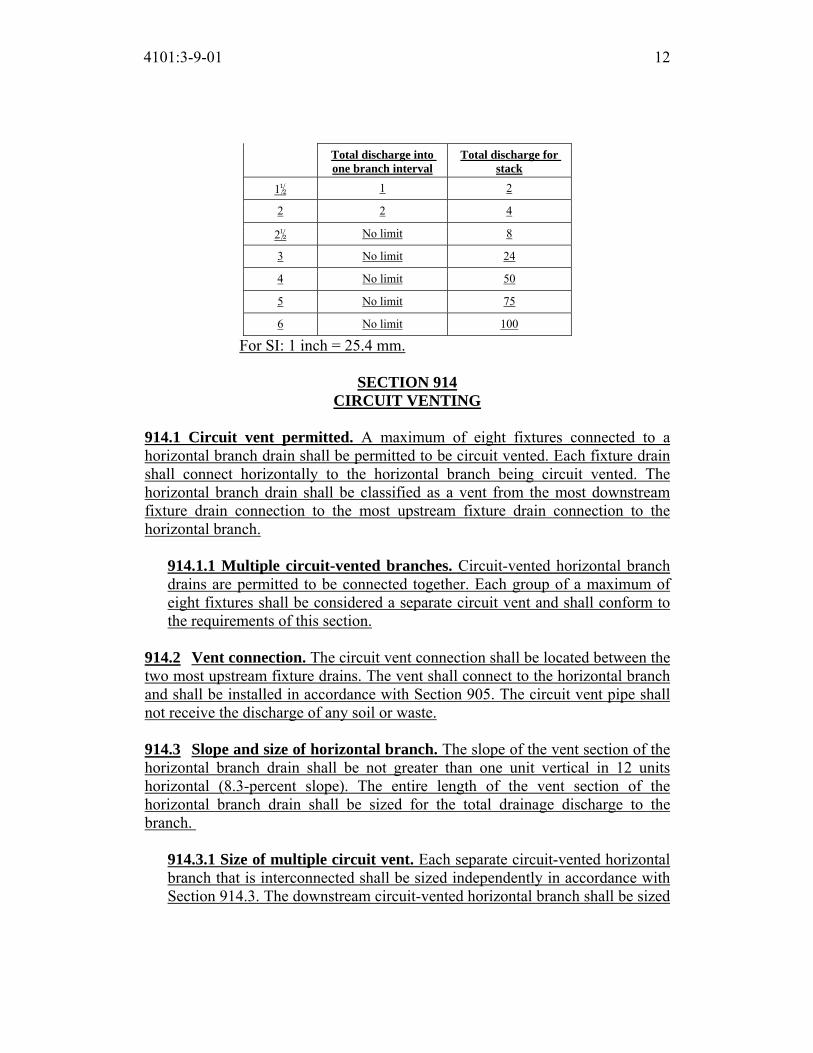
4101:3-9-01 12
Total discharge into one branch interval
Total discharge for stack
1½ 1 2
2 2 4
2½ No limit 8
3 No limit 24
4 No limit 50
5 No limit 75
6 No limit 100
For SI: 1 inch = 25.4 mm.
SECTION 914
CIRCUIT VENTING
914.1 Circuit vent permitted. A maximum of eight fixtures connected to a
horizontal branch drain shall be permitted to be circuit vented. Each fixture drain
shall connect horizontally to the horizontal branch being circuit vented. The
horizontal branch drain shall be classified as a vent from the most downstream
fixture drain connection to the most upstream fixture drain connection to the
horizontal branch.
914.1.1 Multiple circuit-vented branches. Circuit-vented horizontal branch
drains are permitted to be connected together. Each group of a maximum of
eight fixtures shall be considered a separate circuit vent and shall conform to
the requirements of this section.
914.2 Vent connection. The circuit vent connection shall be located between the
two most upstream fixture drains. The vent shall connect to the horizontal branch
and shall be installed in accordance with Section 905. The circuit vent pipe shall
not receive the discharge of any soil or waste.
914.3 Slope and size of horizontal branch. The slope of the vent section of the
horizontal branch drain shall be not greater than one unit vertical in 12 units
horizontal (8.3-percent slope). The entire length of the vent section of the
horizontal branch drain shall be sized for the total drainage discharge to the
branch.
914.3.1 Size of multiple circuit vent. Each separate circuit-vented horizontal
branch that is interconnected shall be sized independently in accordance with
Section 914.3. The downstream circuit-vented horizontal branch shall be sized
4101:3-9-01 13
for the total discharge into the branch, including the upstream branches and
the fixtures within the branch.
914.4 Relief vent. A relief vent shall be provided for circuit-vented horizontal
branches receiving the discharge of four or more water closets and connecting to a
drainage stack that receives the discharge of soil or waste from upper horizontal
branches.
914.4.1 Connection and installation. The relief vent shall connect to the
horizontal branch drain between the stack and the most downstream fixture
drain of the circuit vent. The relief vent shall be installed in accordance with
Section 905.
914.4.2 Fixture drain or branch. The relief vent is permitted to be a
fixture drain or fixture branch for fixtures located within the same branch
interval as the circuit-vented horizontal branch. The maximum discharge to a
relief vent shall be four fixture units.
914.5 Additional fixtures. Fixtures, other than the circuit-vented fixtures, are
permitted to discharge to the horizontal branch drain. Such fixtures shall be
located on the same floor as the circuit-vented fixtures and shall be either
individually or common vented.
SECTION 915
COMBINATION WASTE AND VENT SYSTEM
915.1 Type of fixtures. A combination waste and vent system shall not serve
fixtures other than floor drains, sinks, lavatories and drinking fountains.
Combination waste and vent systems shall not receive the discharge from a food
waste disposer or clinical sink.
915.2 Installation. The only vertical pipe of a combination waste and vent
system shall be the connection between the fixture drain of a sink, lavatory or drinking fountain, and the horizontal combination waste and vent pipe. The
vertical distance shall not exceed 8 feet (2438 mm).
915.2.1 Slope. The slope of a horizontal combination waste and vent pipe
shall not exceed one-half unit vertical in 12 units horizontal (4-percent slope)
and shall not be less than that indicated in Table 704.1.

4101:3-9-01 14
915.2.2 Size and length. The size of a combination waste and vent pipe
shall be not less than that indicated in Table 915.2.2. The horizontal length of
a combination waste and vent system shall be unlimited.
TABLE 915.2.2
SIZE OF COMBINATION WASTE AND VENT PIPE
DIAMETER PIPE (inches)
MAXIMUM NUMBER OF DRAINAGE FIXTURE UNITS (dfu)
Connecting to a horizontal branch or stack
Connecting to a building drain or building subdrain
2 3 4
2½ 6 26
3 12 31
4 20 50
5 160 250
6 360 575
For SI: 1 inch = 25.4 mm.
915.2.3 Connection. The combination waste and vent system shall be
provided with a dry vent connected at any point within the system or the
system shall connect to a horizontal drain that serves vented fixtures located
on the same floor. Combination waste and vent systems connecting to
building drains receiving only the discharge from one or more stacks shall be
provided with a dry vent. The vent connection to the combination waste and
vent pipe shall extend vertically to a point not less than 6 inches (152 mm)
above the flood level rim of the highest fixture being vented before offsetting
horizontally.
915.2.4 Vent size. The vent shall be sized for the total drainage fixture unit
load in accordance with Section 906.2.
915.2.5 Fixture branch or drain. The fixture branch or fixture drain shall
connect to the combination waste and vent within a distance specified in
Table 909.1. The combination waste and vent pipe shall be considered the
vent for the fixture.
SECTION 916
ISLAND FIXTURE VENTING

4101:3-9-01 15
916.1 Limitation. Island fixture venting shall not be permitted for fixtures other
than sinks and lavatories. Residential kitchen sinks with a dishwasher waste
connection, a food waste disposer, or both, in combination with the kitchen sink
waste, shall be permitted to be vented in accordance with this section.
916.2 Vent connection. The island fixture vent shall connect to the fixture drain
as required for an individual or common vent. The vent shall rise vertically to
above the drainage outlet of the fixture being vented before offsetting horizontally
or vertically downward. The vent or branch vent for multiple island fixture vents
shall extend to a point not less than 6 inches (152 mm) above the highest island
fixture being vented before connecting to the outside vent terminal.
916.3 Vent installation below the fixture flood level rim. The vent located
below the flood level rim of the fixture being vented shall be installed as required
for drainage piping in accordance with Chapter 7, except for sizing. The vent
shall be sized in accordance with Section 906.2. The lowest point of the island
fixture vent shall connect full size to the drainage system. The connection shall be
to a vertical drain pipe or to the top half of a horizontal drain pipe. Cleanouts shall
be provided in the island fixture vent to permit rodding of all vent piping located
below the flood level rim of the fixtures. Rodding in both directions shall be
permitted through a cleanout.
SECTION 917
SINGLE STACK VENT SYSTEM
917.1 Where permitted. A drainage stack shall serve as a single stack vent
system where sized and installed in accordance with Sections 917.2 through
917.9. The drainage stack and branch piping shall be the vents for the drainage
system. The drainage stack shall have a stack vent.
917.2 Stack size. Drainage stacks shall be sized in accordance with Table 917.2.
Stacks shall be uniformly sized based on the total connected drainage fixture unit
load. The stack vent shall be the same size as the drainage stack. A 3inch (76
mm) stack shall serve not more than two water closets.
TABLE 917.2
SINGLE STACK SIZE
STACK SIZE
MAXIMUM CONNECTED DRAINAGE FIXTURE UNITS

4101:3-9-01 16
(inches) Stacks less than 75 feet in
height
Stacks 75 feet to less than 160 feet in height
Stacks 160 feet and greater in
height
3 24 NP NP
4 225 24 NP
5 480 225 24
6 1,015 480 225
8 2,320 1,015 480
10 4,500 2,320 1,015
12 8,100 4,500 2,320
15 13,600 8,100 4,500
For SI: 1 inch = 25.4 mm, 1 foot = 304.8 mm.
917.3 Branch size. Horizontal branches connecting to a single stack vent system
shall be sized in accordance with Table 710.1(2). Not more than one water closet
shall discharge into a 3-inch (76 mm) horizontal branch at a point within a
developed length of 18 inches (457 mm) measured horizontally from the stack.
Where a water closet is within 18 inches (457 mm) measured horizontally from
the stack and not more than one fixture with a drain size of not more than 11/2
inches (38 mm) connects to a 3-inch (76 mm) horizontal branch, the branch drain
connection to the stack shall be made with a sanitary tee.
917.4 Length of horizontal branches. The length of horizontal branches shall
conform to the requirements of Sections 917.4.1 through 917.4.3.
917.4.1 Water closet connection. Water closet connections shall be not
greater than 4 feet (1219 mm) in developed length measured horizontally from
the stack.
Exception: Where the connection is made with a sanitary tee, the
maximum developed length shall be 8 feet (2438 mm).
917.4.2 Fixture connections. Fixtures other than water closets shall be
located not greater than 12 feet (3657 mm) in developed length, measured
horizontally from the stack.
917.4.3 Vertical piping in branch. The length of vertical piping in a
fixture drain connecting to a horizontal branch shall not be considered in

4101:3-9-01 17
computing the fixture’s distance in developed length measured horizontally
from the stack.
917.5 Minimum vertical piping size from fixture. The vertical portion of
piping in a fixture drain to a horizontal branch shall be 2 inches (51 mm). The
minimum size of the vertical portion of piping for a water-supplied urinal or
standpipe shall be 3 inches (76 mm). The maximum vertical drop shall be 4 feet
(1219 mm). Fixture drains that are not increased in size, or have a vertical drop
in excess of 4 feet (1219 mm), shall be individually vented.
917.6 Additional venting required. Additional venting shall be provided where
more than one water closet discharges to a horizontal branch and where the
distance from a fixture trap to the stack exceeds the limits in Section 917.4.
Where additional venting is required, the fixture(s) shall be vented by individual
vents, common vents, wet vents, circuit vents, or a combination waste and vent
pipe. The dry vent extensions for the additional venting shall connect to a branch
vent, vent stack, stack vent, air admittance valve, or shall terminate outdoors.
917.7 Stack offsets. Where fixture drains are not connected below a horizontal
offset in a stack, a horizontal offset shall not be required to be vented. Where
horizontal branches or fixture drains are connected below a horizontal offset in a
stack, the offset shall be vented in accordance with Section 907. Fixture
connections shall not be made to a stack within 2 feet (610 mm) above or below a
horizontal offset.
917.8 Prohibited lower connections. Stacks greater than 2 branch intervals in
height shall not receive the discharge of horizontal branches on the lower two
floors. There shall be no connections to the stack between the lower two floors
and a distance of not less than 10 pipe diameters downstream from the base of the
single stack vented system.
917.9 Sizing building drains and sewers. The building drain and building
sewer receiving the discharge of a single stack vent system shall be sized in
accordance with Table 710.1(1).
SECTION 918
AIR ADMITTANCE VALVES
918.1 General. Vent systems utilizing air admittance valves shall comply with
this section. Stack-type air admittance valves shall conform to ASSE 1050.
Individual and branch type air admittance valves shall conform to ASSE 1051.

4101:3-9-01 18
918.2 Installation. The valves shall be installed in accordance with the
requirements of this section and the manufacturer’s instructions. Air admittance
valves shall be installed after the DWV testing required by Section 312.2 or 312.3
has been performed.
918.3 Where permitted. Individual, branch and circuit vents shall be permitted
to terminate with a connection to an individual or branch-type air admittance
valve in accordance with Section 918.3.1. Stack vents and vent stacks shall be
permitted to terminate to stack-type air admittance valves in accordance with
Section 918.3.2.
918.3.1 Horizontal branches. Individual and branch-type air admittance
valves shall vent only fixtures that are on the same floor level and connect to a
horizontal branch drain. Where the horizontal branch is located more than
four branch intervals from the top of the stack, the horizontal branch shall be
provided with a relief vent that shall connect to a vent stack or stack vent, or
extend outdoors to the open air. The relief vent shall connect to the horizontal
branch drain between the stack and the most downstream fixture drain
connected to the horizontal branch drain. The relief vent shall be sized in
accordance with Section 906.2 and installed in accordance with Section 905.
The relief vent shall be permitted to serve as the vent for other fixtures.
918.3.2 Stack. Stack-type air admittance valves shall be prohibited from
serving as the vent terminal for vent stacks or stack vents that serve drainage
stacks having more than six branch intervals.
918.4 Location. Individual and branch-type air admittance valves shall be
located a minimum of 4 inches (102 mm) above the horizontal branch drain or
fixture drain being vented. Stack-type air admittance valves shall be located not
less than 6 inches (152 mm) above the flood level rim of the highest fixture being
vented. The air admittance valve shall be located within the maximum developed
length permitted for the vent. The air admittance valve shall be installed not less
than 6 inches (152 mm) above insulation materials.
918.5 Access and ventilation. Access shall be provided to all air admittance
valves. Such valves shall be installed in a location that allows air to enter the
valve.
918.6 Size. The air admittance valve shall be rated in accordance with the
standard for the size of the vent to which the valve is connected.

4101:3-9-01 19
918.7 Vent required. Within each plumbing system, not less than one stack vent
or vent stack shall extend outdoors to the open air.
918.8 Prohibited installations. Air admittance valves shall not be installed in
nonneutralized special waste systems as described in Chapter 8 except where such
valves are in compliance with ASSE 1049, are constructed of materials approved
in accordance with Section 702.5 and are tested for chemical resistance in
accordance with ASTM F 1412. Air admittance valves shall not be located in
spaces utilized as supply or return air plenums or where limited by the manufacturer’s installation instructions. Air admittance valves without an
engineered design shall not be utilized to vent sumps or tanks of any type.
SECTION 919
ENGINEERED VENT SYSTEMS
919.1 General. Engineered vent systems shall comply with this section and the
design, submittal, approval, inspection and testing requirements of Section 106.5 of the building code.
919.2 Individual branch fixture and in dividual fixture header vents. The
maximum developed length of individual fixture vents to vent branches and vent
headers shall be determined in accordance with Table 919.2 for the minimum
pipe diameters at the indicated vent airflow rates.
The individual vent airflow rate shall be determined in accordance with the
following:
Qh,b = Nn,b Qv (Equation 9-1)
For SI: Qh,b = Nn,b Qv (0.4719 L/s)
where:
Nn,b = Number of fixtures per header (or vent
branch) ÷ total number of fixtures
connected to vent stack.
Qh,b = Vent branch or vent header airflow rate
(cfm).
Qv = Total vent stack airflow rate (cfm).
Qv (gpm) = 27.8 rs 2/3 (1 – rs) D 8/3
Qv (cfm) = 0.134 Qv (gpm) where:
D = Drainage stack diameter (inches).

4101:3-9-01 20
Qw = Design discharge load (gpm).
rs = Waste water flow area to total area.
噺 芸調にば┻ぱ経腿【戴
Individual vent airflow rates are obtained by equally distributing Qh,b into one-
half the total number of fixtures on the branch or header for more than two
fixtures; for an odd number of total fixtures, decrease by one; for one fixture,
apply the full value of Qh,b. Individual vent developed length shall be increased by 20 percent of the distance
from the vent stack to the fixture vent connection on the vent branch or header.
TABLE 919.2
MINIMUM DIAMETER AND MAXIMU M LENGTH OF INDIVIDUAL BRANCH FIXTURE VENTS AND
INDIVIDUAL FIXTURE HEADER VENTS FOR SMOOTH PIPES
DIAMETER OF VENT PIPE (inches)
INDIVIDUAL VENT AIRFLOW RATE (cubic feet per minute)
Maximum developed length of vent (feet)
1 2 3 4 5 6 7 8 9 10 11 12 13 14 15 16 17 18 19 20
½ 95 25 13 8 5 4 3 2 1 1 1 1 1 1 1 1 1 1 1 1
¾ 100 88 47 30 20 15 10 9 7 6 5 4 3 3 3 2 2 2 2 1
1 — — 100 94 65 48 37 29 24 20 17 14 12 11 9 8 7 7 6 6
1¼ — — — — — — — 100 87 73 62 53 46 40 36 32 29 26 23 21
1½ — — — — — — — — — — — 100 96 84 75 65 60 54 49 45
2 — — — — — — — — — — — — — — — — — — — 100
For SI: 1 inch = 25.4 mm, 1 cubic foot per minute = 0.4719 L/s, 1 foot = 304.8 mm.
SECTION 920 COMPUTERIZED VENT DESIGN
920.1 Design of vent system. The sizing, design and layout of the vent system
shall be permitted to be determined by approved computer program design
methods.
920.2 System capacity. The vent system shall be based on the air capacity
requirements of the drainage system under a peak load condition.

Replaces: 4101:3-9-01
Effective: 11/01/2017
Five Year Review (FYR) Dates: 11/01/2022
CERTIFIED ELECTRONICALLY
Certification
05/26/2017
Date
Promulgated Under: 119.03Statutory Authority: 3781.10(A), 4104.43(A)(1)Rule Amplifies: 3781.10, 3781.11, 3791.04Prior Effective Dates: 7/1/98, 1/1/02, 8/15/03, 7/1/07, 11/1/11, 3/15/12,
1/1/16
4101:3-9-01 21

4101:3-10-01 Traps, interceptors and separators.
[Comment: When a reference is made within this rule to a federal statutory provision, an industry consensus standard, or any other technical publication, the specific date and title of the publication as well as the name and address of the promulgating agency are listed in rule 4101:3-15-01 of the Administrative Code. The application of the referenced standards shall be limited and as prescribed in section 102.5 of rule 4101:1-1-01 of the Administrative Code.]
SECTION 1001 GENERAL
1001.1 Scope. This chapter shall govern the material and installation of traps, interceptors and separators when installed inside a building and not on the building sewer. The rules of the “Ohio Environmental Protection Agency” may also govern the design and installation of pretreatment devices such as traps, interceptors, and separators.
SECTION 1002 TRAP REQUIREMENTS
1002.1 Fixture traps. Each plumbing fixture shall be separately trapped by a liquid-seal trap, except as otherwise permitted by this code. The vertical distance from the fixture outlet to the trap weir shall not exceed 24 inches (610 mm), and the horizontal distance shall not exceed 30 inches (610 mm) measured from the centerline of the fixture outlet to the centerline of the inlet of the trap. The height of a clothes washer standpipe above a trap shall conform to Section 802.4. A fixture shall not be double trapped.
Exceptions: 1. This section shall not apply to fixtures with integral traps, floor drains,
floor sinks, and hub drains. 2. A combination plumbing fixture is permitted to be installed on one trap,
provided that one compartment is not more than 6 inches (152 mm) deeper than the other compartment and the waste outlets are not more than 30 inches (762 mm) apart.
3. A grease interceptor intended to serve as a fixture trap in accordance with the manufacturer’s installation instructions shall be permitted to serve as the trap for a single fixture or a combination sink of not more than three compartments where the vertical distance from the fixture outlet to the inlet of the interceptor does not exceed 30 inches (762 mm) and the
ACTION: Final DATE: 05/26/2017 2:37 PM
RB p(170947) pa(315228) d(672539) ra(523775) print date: 06/01/2017 8:37 AM

4101:3-10-01 2
developed length of the waste pipe from the most upstream fixture outlet to the inlet of the interceptor does not exceed 60 inches (1524 mm).
4. Floor drains in multilevel parking structures that discharge to a building storm sewer shall not be required to be individually trapped. Where floor drains in multilevel parking structures are required to discharge to a combined building sewer system, the floor drains shall not be required to be individually trapped provided that they are connected to a main trap in accordance with Section 1103.1.
1002.2 Design of traps. Fixture traps shall be self-scouring. Fixture traps shall not have interior partitions, except where such traps are integral with the fixture or where such traps are constructed of an approved material that is resistant to corrosion and degradation. Slip joints shall be made with an approved elastomeric gasket and shall be installed only on the trap inlet, trap outlet and within the trap seal. 1002.3 Prohibited traps. The following types of traps are prohibited:
1. Traps that depend on moving parts to maintain the seal. 2. Bell traps. 3. Crown-vented traps. 4. Traps not integral with a fixture and that depend on interior partitions for
the seal, except those traps constructed of an approved material that is resistant to corrosion and degradation.
5. “S” traps. 6. Drum traps.
Exception: Drum traps used as solids interceptors and drum traps serving chemical waste systems shall not be prohibited.
1002.4 Trap seals. Each fixture trap shall have a liquid seal of not less than 2 inches (51 mm) and not more than 4 inches (102 mm), or deeper for special designs relating to accessible fixtures.
1002.4.1 Trap seal protection. Trap seals of emergency floor drain traps and trap seals subject to evaporation shall be protected by one of the methods in Sections 1002.4.1.1 through 1002.4.1.4.
Exception: Trap seal protection is not required in garage floor drains in one-, two-, and three-family dwellings.
1002.4.1.1 Potable water-supplied trap seal primer valve. A potable water-supplied trap seal primer valve shall supply water to the trap. Water-supplied trap seal primer valves shall conform to ASSE 1018. The

4101:3-10-01 3
discharge pipe from the trap seal primer valve shall connect to the trap above the trap seal on the inlet side of the trap.
1002.4.1.2 Reclaimed or gray water-supplied trap seal primer valve. A reclaimed or gray water-supplied trap seal primer valve shall supply water to the trap. Water-supplied trap seal primer valves shall conform to ASSE 1018. The quality of reclaimed or gray water supplied to trap seal primer valves shall be in accordance with the requirements of the manufacturer of the trap seal primer valve. The discharge pipe from the trap seal primer valve shall connect to the trap above the trap seal, on the inlet side of the trap. 1002.4.1.3 Waste water-supplied trap primer device. A waste water-supplied trap primer device shall supply water to the trap. Waste water-supplied trap primer devices shall conform to ASSE 1044. The discharge pipe from the trap seal primer device shall connect to the trap above the trap seal on the inlet side of the trap. 1002.4.1.4 Barrier-type trap seal protection device. A barrier-type trap seal protection device shall protect the floor drain trap seal from evaporation. Barrier-type floor drain trap seal protection devices shall conform to ASSE 1072. The devices shall be installed in accordance with the manufacturer’s instructions.
1002.5 Size of fixture traps. Fixture trap size shall be sufficient to drain the fixture rapidly and not less than the size indicated in Table 709.1. A trap shall not be larger than the drainage pipe into which the trap discharges. 1002.6 Building traps. Building (house) traps shall be prohibited. 1002.7 Trap setting and protection. Traps shall be set level with respect to the trap seal and, where necessary, shall be protected from freezing. 1002.8 Recess for trap connection. A recess provided for connection of the underground trap, such as one serving a bathtub in slab-type construction, shall have sides and a bottom of corrosion-resistant, insect- and vermin-proof construction. 1002.9 Acid-resisting traps. Where a vitrified clay or other brittleware, acid-resisting trap is installed underground, such trap shall be embedded in concrete extending 6 inches (152 mm) beyond the bottom and sides of the trap.

4101:3-10-01 4
1002.10 Plumbing in mental health centers. In mental health centers, pipes and traps shall not be exposed.
SECTION 1003 INTERCEPTORS AND SEPARATORS
1003.1 Where required. Where required by the local sewer purveyor or as otherwise required in this section, interceptors and separators shall be provided to prevent the discharge of oil, grease, sand and other substances harmful or hazardous to the public sewer, the private sewage system or the sewage treatment plant or processes.
1003.1.1 Industrial processes, meat packing and food processing facilities. Wastes from industrial processes, meat packing and food processing facilities and similar processing plants shall be drained in accordance with the rules of the “Ohio Environmental Protection Agency”, or the authority in charge of the sewerage system into which the wastes are to be discharged. (See sections 6111.44 and 6111.45 of the Revised Code.)
1003.2 Approval. The size, type and location of each interceptor and of each separator shall be designed and installed in accordance with the manufacturer’s instructions and the requirements of this section based on the anticipated conditions of use. Wastes that do not require treatment or separation shall not be discharged into any interceptor or separator. 1003.3 Grease interceptors. Grease interceptors shall comply with the requirements of Sections 1003.3.1 through 1003.3.5.
1003.3.1 Grease interceptors and automatic grease removal devices required. A grease interceptor or automatic grease removal device shall be required to receive the drainage from fixtures and equipment with grease-laden waste located in food preparation areas, such as in restaurants, hotel kitchens, hospitals, school kitchens, bars, factory cafeterias and clubs. Fixtures and equipment shall include pot sinks, prerinse sinks; soup kettles or similar devices; wok stations; floor drains or sinks into which kettles are drained; automatic hood wash units and dishwashers without prerinse sinks. Grease interceptors and automatic grease removal devices shall receive waste only from fixtures and equipment that allow fats, oils or grease to be discharged. Where lack of space or other constraints prevent the installation or replacement of a grease interceptor, one or more grease interceptors shall be

4101:3-10-01 5
permitted to be installed on or above the floor and upstream of an existing grease interceptor.
1003.3.2 Food waste disposers. Where food waste disposers connect to grease interceptors, a solids interceptor shall separate the discharge before connecting to the grease interceptor. Solids interceptors and grease interceptors shall be sized and rated for the discharge of the food waste disposers. Emulsifiers, chemicals, enzymes and bacteria shall not discharge into the food waste disposer. 1003.3.3 Grease interceptors and automatic grease removal devices not required. A grease interceptor or an automatic grease removal device shall not be required for individual dwelling units or any private living quarters. 1003.3.4 Hydromechanical grease interceptors, fats, oils and greases disposal systems and automatic grease removal devices. Hydromechanical grease interceptors; fats, oils, and greases disposal systems and automatic grease removal devices shall be sized in accordance with ASME A112.14.3, ASME 112.14.4, ASME A112.14.6, CSA B481.3 or PDI G101. Hydromechanical grease interceptors; fats, oils, and greases disposal systems and automatic grease removal devices shall be designed and tested in accordance with ASME A112.14.3, ASME 112.14.4, CSA B481.1, PDI G101 or PDI G102. Hydromechanical grease interceptors; fats, oils, and greases disposal systems and automatic grease removal devices shall be installed in accordance with the manufacturer’s instructions. Where manufacturer’s instructions are not provided, hydromechanical grease interceptors; fats, oils, and greases disposal systems and automatic grease removal devices shall be installed in compliance with ASME A112.14.3, ASME 112.14.4, ASME A112.14.6, CSA B481.3 or PDI G101.
1003.3.4.1 Grease interceptor capacity. Grease interceptors shall have the grease retention capacity indicated in Table 1003.3.4.1 for the flow-through rates indicated. 1003.3.4.2 Rate of flow controls. Grease interceptors shall be equipped with devices to control the rate of water flow so that the water flow does not exceed the rated flow. The flow-control device shall be vented and terminate not less than 6 inches (152 mm) above the flood rim level or be installed in accordance with the manufacturer’s instructions.
1003.3.5 Automatic grease removal devices. Where automatic grease

4101:3-10-01 6
removal devices are installed, such devices shall be located downstream of each fixture or multiple fixtures in accordance with the manufacturer’s instructions. The automatic grease removal device shall be sized to pretreat the measured or calculated flows for all connected fixtures or equipment. Ready access shall be provided for inspection and maintenance.
TABLE 1003.3.4.1
CAPACITY OF GREASE INTERCEPTORSa TOTAL FLOW-
THROUGH RATING (gpm)GREASE RETENTION
CAPACITY (pounds)
4 8
6 12
7 14
9 18
10 20
12 24
14 28
15 30
18 36
20 40
25 50
35 70
50 100
75 150
100 200
For SI: 1 gallon per minute = 3.785 L/m, 1 pound = 0.454 kg. a. For total flow-through ratings greater than 100 (gpm), double
the flowthrough rating to determine the grease retention capacity (pounds).
1003.3.6 Gravity grease interceptors and gravity grease interceptors with fats, oils, and greases disposal systems. The required capacity of gravity grease interceptors and gravity grease interceptors with fats, oils, and greases disposal systems shall be determined by multiplying the peak drain flow into the interceptor in gallons per minute by a retention time of 30 minutes. Gravity grease interceptors shall be designed and tested in accordance with IAPMO/ANSI Z1001. Gravity grease interceptors with fats, oils, and greases disposal systems shall be designed and tested in accordance with ASME A112.14.6 and IAPMO/ANSI Z1001. Gravity grease interceptors and gravity

4101:3-10-01 7
grease interceptors with fats, oils, and greases disposal systems shall be installed in accordance with manufacturer’s instructions. Where manufacturer’s instructions are not provided, gravity grease interceptors and gravity grease interceptors with fats, oils, and greases disposal systems shall be installed in compliance with ASME A112.14.6 and IAPMO/ANSI Z1001.
1003.3.7 Direct connection. The discharge piping from a grease interceptor shall be directly connected to the sanitary drainage system.
1003.4 Oil separators required. At repair garages where floor or trench drains are provided, car washing facilities, factories where oily and flammable liquid wastes are produced, oil separators shall be installed into which oil-bearing, grease-bearing or flammable wastes shall be discharged before emptying into the building drainage system or other point of disposal.
1003.4.1 Separation of liquids. A mixture of treated or untreated light and heavy liquids with various specific gravities shall be separated in an approved receptacle. 1003.4.2 Oil separator design. Oil separators shall be listed and labeled, or designed in accordance with Sections 1003.4.2.1 and 1003.4.2.2.
1003.4.2.1 General design requirements. Oil separators shall have a depth of not less than 2 feet (610 mm) below the invert of the discharge drain. The outlet opening of the separator shall have not less than an 18inch (457 mm) water seal. 1003.4.2.2 Garages and service stations. Where automobiles are serviced, greased, repaired or washed or where gasoline is dispensed, oil separators shall have a capacity of not less than 6 cubic feet (0.168 m3) for the first 100 square feet (9.3 m2) of area to be drained, plus 1 cubic foot (0.028 m3) for each additional 100 square feet (9.3 m2) of area to be drained into the separator. Parking garages in which servicing, repairing or washing is not conducted, and in which gasoline is not dispensed, shall not require a separator. Areas of commercial garages utilized only for storage of automobiles are not required to be drained through a separator.
1003.5 Sand interceptors in commercial establishments. Sand and similar interceptors for heavy solids shall be designed and located so as to be provided with ready access for cleaning, and shall have a water seal of not less than 6 inches (152 mm).

4101:3-10-01 8
1003.6 Clothes washer discharge interceptor. Clothes washers shall discharge through an interceptor that is provided with a wire basket or similar device, removable for cleaning, that prevents passage into the drainage system of solids 1/2 inch (12.7 mm) or larger in size, string, rags, buttons or other materials detrimental to the public sewage system.
Exceptions: 1. Clothes washers in individual dwelling units shall not be required to
discharge through an interceptor. 2. A single clothes washer designed for use in individual dwelling units and
installed in a location other than an individual dwelling unit shall not be required to discharge through an interceptor.
1003.7 Bottling establishments. Bottling plants shall discharge process wastes into an interceptor that will provide for the separation of broken glass or other solids before discharging waste into the drainage system. 1003.8 Slaughterhouses. Slaughtering room and dressing room drains shall be equipped with approved separators. The separator shall prevent the discharge into the drainage system of feathers, entrails and other materials that cause clogging. 1003.9 Venting of interceptors and separators. Interceptors and separators shall be designed so as not to become air bound. Interceptors and separators shall be vented in accordance with one of the methods in Chapter 9. 1003.10 Access and maintenance of interceptors and separators. Access shall be provided to each interceptor and separator for service and maintenance. Interceptors and separators shall be maintained by periodic removal of accumulated grease, scum, oil, or other floating substances and solids deposited in the interceptor or separator.
SECTION 1004 MATERIALS, JOINTS AND CONNECTIONS
1004.1 General. The materials and methods utilized for the construction and installation of traps, interceptors and separators shall comply with this chapter and the applicable provisions of Chapters 4 and 7. The fittings shall not have ledges, shoulders or reductions capable of retarding or obstructing flow of the piping.

Replaces: 4101:3-10-01
Effective: 11/01/2017
Five Year Review (FYR) Dates: 11/01/2022
CERTIFIED ELECTRONICALLY
Certification
05/26/2017
Date
Promulgated Under: 119.03Statutory Authority: 3781.10(A)Rule Amplifies: 3781.03(D), 3781.10, 3781.11, 3791.04Prior Effective Dates: 3/1/98, 4/1/99, 1/1/02, 7/1/07, 11/1/11, 7/1/14
4101:3-10-01 9
4101:3-11-01 Storm drainage.
[Comment: When a reference is made within this rule to a federal statutory provision, an industry consensus standard, or any other technical publication, the specific date and title of the publication as well as the name and address of the promulgating agency are listed in rule 4101:3-15-01 of the Administrative Code. The application of the referenced standards shall be limited and as prescribed in section 102.5 of rule 4101:1-1-01 of the Administrative Code.]
SECTION 1101 GENERAL
1101.1 Scope. The provisions of this chapter shall govern the materials, design,
construction and installation of storm drainage.
1101.2 Disposal. Rainwater from roofs and storm water from paved areas, yards,
courts and courtyards in buildings shall drain to an approved place of disposal.
For one-, two-, and three- family dwellings, and where approved, storm water is
permitted to discharge onto flat areas, such as streets or lawns, provided that the
storm water flows away from the building.
1101.3 Prohibited drainage. Storm water shall not be drained into sewers
intended for sewage only.
1101.4 Tests. The conductors and the building storm drain shall be tested in
accordance with Section 312.
1101.5 Change in size. The size of a drainage pipe shall not be reduced in the
direction of flow.
1101.6 Fittings and connections. All connections and changes in direction of the
storm drainage system shall be made with approved drainage-type fittings in
accordance with Table 706.3. The fittings shall not obstruct or retard flow in the
system.
1101.7 Roof design. Roofs shall be designed for the maximum possible depth of
water that will pond thereon as determined by the relative levels of roof deck and
overflow weirs, scuppers, edges or serviceable drains in combination with the
deflected structural elements. In determining the maximum possible depth of
water, all primary roof drainage means shall be assumed to be blocked. The
maximum possible depth of water on the roof shall include the height of the water
ACTION: Final DATE: 05/26/2017 2:37 PM
RB p(170947) pa(315228) d(672540) ra(523774) print date: 06/01/2017 8:38 AM

4101:3-11-01 2
required above the inlet of the secondary roof drainage means to achieve the
required flow rate of the secondary drainage means to accommodate the design
rainfall rate as required by Section 1106.
1101.8 Cleanouts required. Cleanouts shall be installed in the storm drainage
system and shall comply with the provisions of this code for sanitary drainage
pipe cleanouts.
Exception: Subsurface drainage system.
1101.9 Backwater valves. Storm drainage systems shall be provided with
backwater valves as required for sanitary drainage systems in accordance with
Section 715.
SECTION 1102 MATERIALS
1102.1 General. The materials and methods utilized for the construction and
installation of storm drainage systems shall comply with this section and the
applicable provisions of Chapter 7.
1102.2 Inside storm drainage conductors. Inside storm drainage conductors
installed above ground shall conform to one of the standards listed in Table 702.1.
1102.3 Underground building storm drain pipe. Underground building storm
drain pipe shall conform to one of the standards listed in Table 702.2.
1102.4 Building storm sewer pipe. Deleted. TABLE 1102.4 BUILDING STORM SEWER PIPE Deleted. 1102.5 Subsoil drain pipe. Subsoil drains shall be open jointed, horizontally split
or perforated pipe conforming to one of the standards listed in Table 1102.5.
TABLE 1102.5
SUBSOIL DRAIN PIPE
MATERIAL STANDARD
Cast-iron pipe ASTM A 74; ASTM A 888;
CISPI 301
Polyethylene (PE) plastic pipe ASTM F 405; CSA B182.1;
CSA B182.6; CSA B182.8

4101:3-11-01 3
Polyvinyl chloride (PVC)
Plastic pipe (type sewer pipe,
SDR35, PS25, PS50 or
PS100)
ASTM D 2729; ASTM D 3034,
ASTM F 891; CSA B182.2; CSA
B182.4
Stainless steel drainage systems,
Type 316L ASME A 112.3.1
Vitrified clay pipe ASTM C 4; ASTM C 700
1102.6 Roof Drains. Roof drains shall conform to ASME A112.6.4 or ASME
A112.3.1.
1102.7 Fittings. Pipe fittings shall be approved for installation with the piping
material installed, and shall conform to the respective pipe standards or one of the
standards listed in Table 1102.7. The fittings shall not have ledges, shoulders or
reductions capable of retarding or obstructing flow in the piping. Threaded
drainage pipe fittings shall be of the recessed drainage type.
TABLE 1102.7 PIPE FITTING
MATERIAL STANDARD
Acrylonitrile butadiene
styrene (ABS) plastic
ASTM D 2661; ASTM D 3311;
CSA B181.1
Cast-iron
ASME B16.4; ASME B16.12;
ASTM A 888; CISPI 301;
ASTM A 74
Coextruded composite ABS
and drain DR-PS in
PS35, PS50, PS100, PS140,
PS200
ASTM D 2751
Coextruded composite ABS
DWV Schedule 40 IPS pipe
(solid or cellular core)
ASTM D 2661; ASTM D 3311;
ASTM F 628
Coextruded composite PVC
DWV Schedule 40 IPS-DR,
PS140, PS200 (solid or
cellular core)
ASTM D 2665; ASTM D 3311;
ASTM F 891
Coextruded composite PVC
sewer and drain DR-PS in
PS35, PS50, PS100, PS140,
PS200
ASTM D 3034
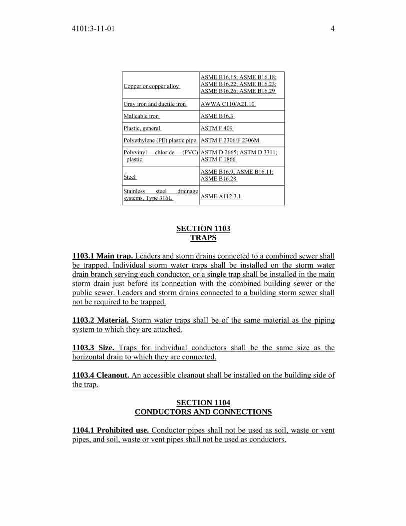
4101:3-11-01 4
Copper or copper alloy
ASME B16.15; ASME B16.18;
ASME B16.22; ASME B16.23;
ASME B16.26; ASME B16.29
Gray iron and ductile iron AWWA C110/A21.10
Malleable iron ASME B16.3
Plastic, general ASTM F 409
Polyethylene (PE) plastic pipe ASTM F 2306/F 2306M
Polyvinyl chloride (PVC)
plastic
ASTM D 2665; ASTM D 3311;
ASTM F 1866
Steel ASME B16.9; ASME B16.11;
ASME B16.28
Stainless steel drainage
systems, Type 316L ASME A112.3.1
SECTION 1103 TRAPS
1103.1 Main trap. Leaders and storm drains connected to a combined sewer shall
be trapped. Individual storm water traps shall be installed on the storm water
drain branch serving each conductor, or a single trap shall be installed in the main
storm drain just before its connection with the combined building sewer or the
public sewer. Leaders and storm drains connected to a building storm sewer shall
not be required to be trapped.
1103.2 Material. Storm water traps shall be of the same material as the piping
system to which they are attached.
1103.3 Size. Traps for individual conductors shall be the same size as the
horizontal drain to which they are connected.
1103.4 Cleanout. An accessible cleanout shall be installed on the building side of
the trap.
SECTION 1104
CONDUCTORS AND CONNECTIONS
1104.1 Prohibited use. Conductor pipes shall not be used as soil, waste or vent
pipes, and soil, waste or vent pipes shall not be used as conductors.

4101:3-11-01 5
1104.2 Floor drains. Floor drains shall not be connected to a storm drain.
SECTION 1105 ROOF DRAINS
1105.1 General. Roof drains shall be installed in accordance with the
manufacturer’s instructions. The inside opening for the roof drain shall not be
obstructed by the roofing membrane material.
1105.2 Roof drain flow rate. The published roof drain flow rate, based on the
head of water above the roof drain, shall be used to size the storm drainage
system in accordance with Section 1106. The flow rate used for sizing the storm
drainage piping shall be based on the maximum anticipated ponding at the roof
drain.
SECTION 1106
SIZE OF CONDUCTORS, LEADERS AND STORM DRAINS

4101:3-11-01 6
1106.1 General. The size of the vertical conductors and leaders, building storm
drains, and any horizontal branches of such drains shall be based on the 100-year
hourly rainfall rate indicated in Figure 1106.1 or on other rainfall rates
determined from approved local weather data.
For SI: 1 inch = 25.4 mm.
Source: National Weather Service, National Oceanic and Atmospheric
Administration, Washington D.C.
FIGURE 1106.1
100-YEAR, 1-HOUR RAINFALL (INCHES) EASTERN UNITED STATES

4101:3-11-01 7
For SI: 1 inch = 25.4 mm.
Source: National Weather Service, National Oceanic and Atmospheric
Administration, Washington D.C.
FIGURE 1106.1 (ENLARGED) 100-YEAR, 1-HOUR RAINFALL (INCHES) EASTERN UNITED STATES
1106.2 Size of storm drain piping. Vertical and horizontal storm drain piping
shall be sized based on the flow rate through the roof drain. The flow rate in

4101:3-11-01 8
storm drain piping shall not exceed that specified in Table 1106.2.
1106.3 Vertical leader sizing. Vertical leaders shall be sized based on the flow
rate from horizontal gutters or the maximum flow rate through roof drains. The
flow rate through vertical leaders shall not exceed that specified in Table 1106.3.
1106.4 Vertical walls. In sizing roof drains and storm drainage piping, one-half
of the area of any vertical wall that diverts rainwater to the roof shall be added to
the projected roof area for inclusion in calculating the required size of vertical
conductors, leaders and horizontal storm drainage piping.
1106.5 Parapet wall scupper location. Parapet wall roof drainage scupper and
overflow scupper location shall comply with the requirements of Section 1503.4
of the building code.
1106.6 Size of roof gutters. Horizontal gutters shall be sized based on the flow
rate from the roof surface. The flow rate in horizontal gutters shall not exceed that
specified in Table 1106.6.
SECTION 1107
SIPHONIC ROOF DRAINAGE SYSTEMS
1107.1 General. Siphonic roof drains and drainage systems shall be designed in
accordance with ASME A112.6.9 and ASPE 45.
SECTION 1108
SECONDARY (EMERGENCY) ROOF DRAINS
1108.1 Secondary (emergency overflow) drains or scuppers. Where roof
drains are required, secondary (emergency overflow) roof drains or scuppers shall
be provided where the roof perimeter construction extends above the roof in such
a manner that water will be entrapped if the primary drains allow buildup for any
reason. Where primary and secondary roof drains are manufactured as a single
assembly, the inlet and outlet for each drain shall be independent.
1108.2 Separate systems required. Secondary roof drain systems shall have the
end point of discharge separate from the primary system. Discharge shall be
above grade, in a location that would normally be observed by the building
occupants or maintenance personnel.
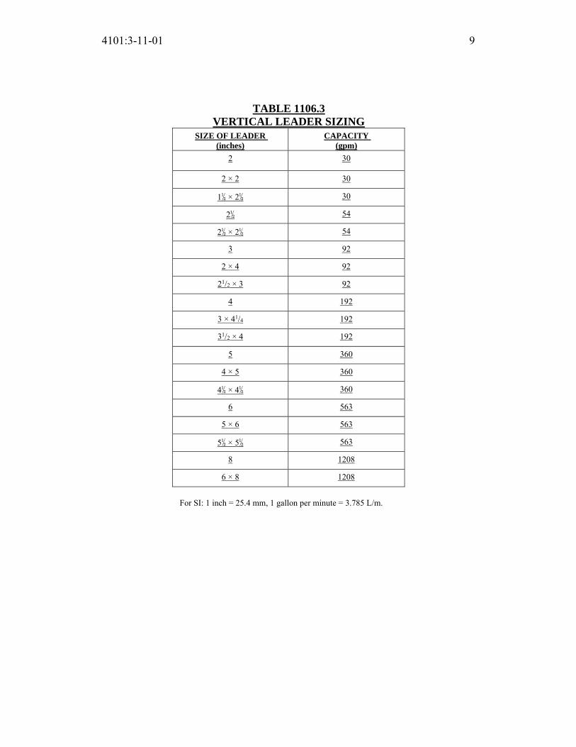
4101:3-11-01 9
TABLE 1106.3
VERTICAL LEADER SIZING
SIZE OF LEADER (inches)
CAPACITY (gpm)
2 30
2 × 2 30
1½ × 2½ 30
2½ 54
2½ × 2½ 54
3 92
2 × 4 92
21/2 × 3 92
4 192
3 × 41/4 192
31/2 × 4 192
5 360
4 × 5 360
4½ × 4½ 360
6 563
5 × 6 563
5½ × 5½ 563
8 1208
6 × 8 1208
For SI: 1 inch = 25.4 mm, 1 gallon per minute = 3.785 L/m.

4101:3-11-01 10
1108.3 Sizing of secondary drains. Secondary (emergency) roof drain systems
shall be sized in accordance with Section 1106 based on the rainfall rate for
which the primary system is sized. Scuppers shall be sized to prevent the depth of
ponding water from exceeding that for which the roof was designed as
determined by Section 1101.7. Scuppers shall have an opening dimension of not
less than 4 inches (102 mm). The flow through the primary system shall not be
considered when sizing the secondary roof drain system.
SECTION 1109
COMBINED SANITARY AND STORM PUBLIC SEWER
1109.1 General. Deleted.
SECTION 1110 CONTROLLED FLOW ROOF DRAIN SYSTEMS
1110.1 General. The roof of a structure shall be designed for the storage of water
where the storm drainage system is engineered for controlled flow. The controlled
flow roof drain system shall be an engineered system in accordance with this
section and the design, submittal, approval, inspection and testing requirements of
TABLE 1106.2 STORM DRAIN PIPE SIZING
PIPE SIZE
(inches)
CAPACITY (gpm)
VERTICAL DRAIN
SLOPE OF HORIZONTAL DRAIN
1 /16 inch per foot
1 /8 inch per foot
1 /4 inch per foot
1 /2 inch per foot
2 34 15 22 31 44
3 87 39 55 79 111
4 180 81 115 163 231
5 311 117 165 234 331
6 538 243 344 487 689
8 1,117 505 714 1,010 1,429
10 2,050 927 1,311 1,855 2,623
12 3,272 1,480 2,093 2,960 4,187
15 5,543 2,508 3,546 5,016 7,093
For SI: 1 inch = 25.4 mm, 1 foot = 304.8 mm, 1 gallon per minute = 3.785 L/m.

4101:3-11-01 11
Sections 106.5, 107, and 108 of the building code and Section 312 of this code.
The controlled flow system shall be designed based on the required rainfall rate in
accordance with Section 1106.1.
1110.2 Control devices. The control devices shall be installed so that the rate of
discharge of water per minute shall not exceed the values for continuous flow as
indicated in Section 1110.1.
1110.3 Installation. Runoff control shall be by control devices. Control devices
shall be protected by strainers.
1110.4 Minimum number of roof drains. Not less than two roof drains shall be
installed in roof areas 10,000 square feet (929 m2) or less and not less than four
roof drains shall be installed in roofs over 10,000 square feet (929 m2) in area.
SECTION 1111
SUBSOIL DRAINS
1111.1 Subsoil drains. Subsoil drains shall be open-jointed, horizontally split or
perforated pipe conforming to one of the standards listed in Table 1102.5. Such
drains shall not be less than 4 inches (102 mm) in diameter. Where the building is
subject to backwater, the subsoil drain shall be protected by an accessibly located
backwater valve. Subsoil drains shall discharge to a trapped area drain, sump, dry
well or approved location above ground. The subsoil sump shall not be required
to have either a gas-tight cover or a vent. The sump and pumping system shall
comply with Section 1113.1.
TABLE 1106.6
HORIZONTAL GUTTER SIZING GUTTER DIMENSIONSa
(inches) SLOPE
(inch per foot) CAPACITY (gpm)
1½ × 2½ ¼ 26
1½ × 2½ ½ 40
4 ╀ 39
21/4 × 3 ¼ 55
21/4 × 3 ½ 87
5 ╀ 74
4 × 21/2 ¼ 106
3 × 31/2 ½ 156

4101:3-11-01 12
6 ╀ 110
3 × 5 ¼ 157
3 × 5 ½ 225
8 1/16 172
8 ╀ 247
41/2 × 6 ¼ 348
41/2 × 6 ½ 494
10 1/16 331
10 ╀ 472
5 × 8 ¼ 651
4 × 10 ½ 1055
For SI: 1 inch = 25.4 mm, 1 foot = 304.8 mm, 1 gallon per minute = 3.785 L/m, 1 inch per foot = 83.3 mm/m.
a. Dimensions are width by depth for rectangular shapes. Single dimensions are diameters of a semicircle.
SECTION 1112
BUILDING SUBDRAINS
1112.1 Building subdrains. Building subdrains located below the public sewer
level shall discharge into a sump or receiving tank, the contents of which shall be
automatically lifted and discharged into the drainage system as required for
building sumps. The sump and pumping equipment shall comply with Section
1113.1.
SECTION 1113
SUMPS AND PUMPING SYSTEMS
1113.1 Pumping system. The sump pump, pit and discharge piping shall
conform to Sections 1113.1.1 through 1113.1.4.
1113.1.1 Pump capacity and head. The sump pump shall be of a capacity
and head appropriate to anticipated use requirements.
1113.1.2 Sump pit. The sump pit shall be not less than 18 inches (457 mm) in
diameter and not less than 24 inches (610 mm) in depth, unless otherwise
approved. The pit shall be accessible and located such that all drainage flows
into the pit by gravity. The sump pit shall be constructed of tile, steel, plastic,
cast iron, concrete or other approved material, with a removable cover
adequate to support anticipated loads in the area of use. The pit floor shall be
solid and provide permanent support for the pump.

4101:3-11-01 13
1113.1.3 Electrical. Electrical service outlets, when required, shall meet the
requirements of NFPA 70.
1113.1.4 Piping. Discharge piping shall meet the requirements of Section
1102.2 or 1102.3 and shall include a full open gate valve and a full flow check
valve. Pipe and fittings shall be the same size as, or larger than, the pump
discharge tapping.
Exception: In buildings where the “Residential Code of Ohio” applies,
only a check valve shall be required, located on the discharge piping from
the pump or ejector.
1113.1.5 Water-powered sump pumps. Water-powered sump pumps are only to be used as a secondary back-up pump for the subsoil drainage system and only with appropriate backflow protection in place as required by Section 608.

Replaces: 4101:3-11-01
Effective: 11/01/2017
Five Year Review (FYR) Dates: 11/01/2022
CERTIFIED ELECTRONICALLY
Certification
05/26/2017
Date
Promulgated Under: 119.03Statutory Authority: 3781.10(A), 4104.43(A)(1)Rule Amplifies: 3781.03(D), 3781.10, 3781.11, 3791.04Prior Effective Dates: 3/1/98, 1/1/02, 7/1/07, 11/1/11
4101:3-11-01 14

4101:3-12-01 Special piping and storage systems.
[Comment: When a reference is made within this rule to a federal statutory provision, an industry consensus standard, or any other technical publication, the specific date and title of the publication as well as the name and address of the promulgating agency are listed in rule 4101:3-15-01 of the Administrative Code. The application of the referenced standards shall be limited and as prescribed in section 102.5 of rule 4101:1-1-01 of the Administrative Code.]
SECTION 1201 GENERAL
1201.1 Scope. The provisions of this chapter and Chapter 53 of the fire code shall govern the design and installation of piping and storage systems for non- flammable medical gas systems and medical oxygen systems. All maintenance and operations of such systems shall be in accordance with Chapter 34 of the building code and the applicable chapters of the fire code.
SECTION 1202 MEDICAL GASES
1202.1 Nonflammable medical gases. Nonflammable medical gas systems, inhalation anesthetic systems and vacuum piping systems shall be designed and installed in accordance with NFPA 99.
Exceptions: 1. This section shall not apply to portable systems or cylinder storage. 2. Deleted.
1202.2 Enforcement. Plan review and inspection of nonflammable medical gas and vacuum systems shall be performed by one of the following:
1. A building department certified to enforce medical gas systems and having in its employ or under contract a certified medical gas inspector; or
2. A local health district requesting enforcement responsibility and having in its employ or under contract a certified medical gas inspector; or
3. If a certified department does not hold the certification to enforce medical gas piping system requirements and a local health district does not request enforcement authority, then the enforcement shall be done by the division of industrial compliance in the department of commerce.
SECTION 1203
OXYGEN SYSTEMS
ACTION: Final DATE: 05/26/2017 2:37 PM
RB p(170947) pa(315228) d(672541) ra(523773) print date: 06/01/2017 8:39 AM

4101:3-12-01 2
1203.1 Design and installation. Deleted.

Replaces: 4101:3-12-01
Effective: 11/01/2017
Five Year Review (FYR) Dates: 11/01/2022
CERTIFIED ELECTRONICALLY
Certification
05/26/2017
Date
Promulgated Under: 119.03Statutory Authority: 3781.10(A), 4104.43(A)(2)Rule Amplifies: 3781.10, 3781.11, 3791.04Prior Effective Dates: 1/1/02, 1/1/04, 3/1/05, 7/1/07, 11/1/11
4101:3-12-01 3
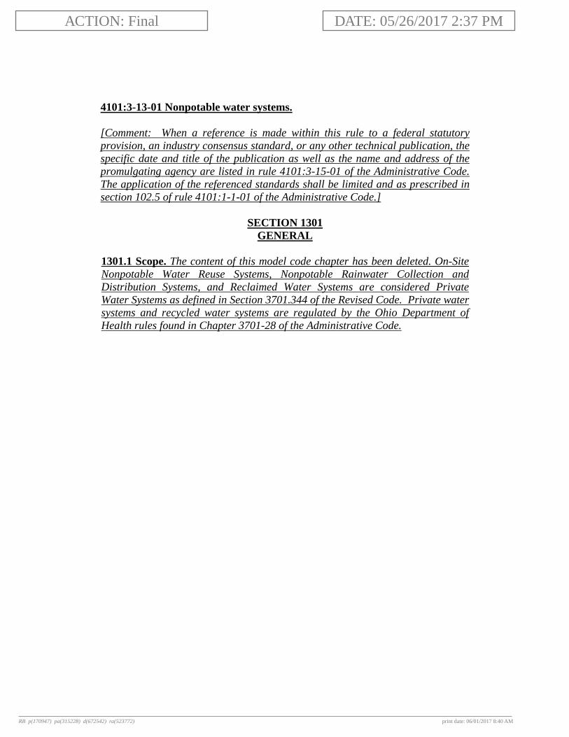
4101:3-13-01 Nonpotable water systems.
[Comment: When a reference is made within this rule to a federal statutory provision, an industry consensus standard, or any other technical publication, the specific date and title of the publication as well as the name and address of the promulgating agency are listed in rule 4101:3-15-01 of the Administrative Code. The application of the referenced standards shall be limited and as prescribed in section 102.5 of rule 4101:1-1-01 of the Administrative Code.]
SECTION 1301 GENERAL
1301.1 Scope. The content of this model code chapter has been deleted. On-Site Nonpotable Water Reuse Systems, Nonpotable Rainwater Collection and Distribution Systems, and Reclaimed Water Systems are considered Private Water Systems as defined in Section 3701.344 of the Revised Code. Private water systems and recycled water systems are regulated by the Ohio Department of Health rules found in Chapter 3701-28 of the Administrative Code.
ACTION: Final DATE: 05/26/2017 2:37 PM
RB p(170947) pa(315228) d(672542) ra(523772) print date: 06/01/2017 8:40 AM

Effective: 11/01/2017
Five Year Review (FYR) Dates: 11/01/2022
CERTIFIED ELECTRONICALLY
Certification
05/26/2017
Date
Promulgated Under: 119.03Statutory Authority: 3781.10(A)Rule Amplifies: 3701.344, 3781.10, 3781.11, 3791.04
4101:3-13-01 2

4101:3-14-01 Subsurface landscape irrigation systems.
[Comment: When a reference is made within this rule to a federal statutory provision, an industry consensus standard, or any other technical publication, the specific date and title of the publication as well as the name and address of the promulgating agency are listed in rule 4101:3-15-01 of the Administrative Code. The application of the referenced standards shall be limited and as prescribed in section 102.5 of rule 4101:1-1-01 of the Administrative Code.]
SECTION 1401 GENERAL
1401.1 Scope. The content of this model code chapter has been deleted. Subsurface landscape irrigation systems connected to nonpotable water from on-site water reuse systems are considered process piping systems (not building services piping systems) and, therefore, exempt from approval in accordance with Section 102.10 of the building code. Private water systems and recycled water systems are regulated by the Ohio Department of Health rules found in Chapter 3701-28 of the Administrative Code.
ACTION: Final DATE: 05/26/2017 2:37 PM
RB p(170947) pa(315228) d(672543) ra(523771) print date: 06/01/2017 8:41 AM

Effective: 11/01/2017
Five Year Review (FYR) Dates: 11/01/2022
CERTIFIED ELECTRONICALLY
Certification
05/26/2017
Date
Promulgated Under: 119.03Statutory Authority: 3781.10(A), 4104.43(A)(1)Rule Amplifies: 3781.10, 3781.11, 3791.04, 4104.41
4101:3-14-01 2
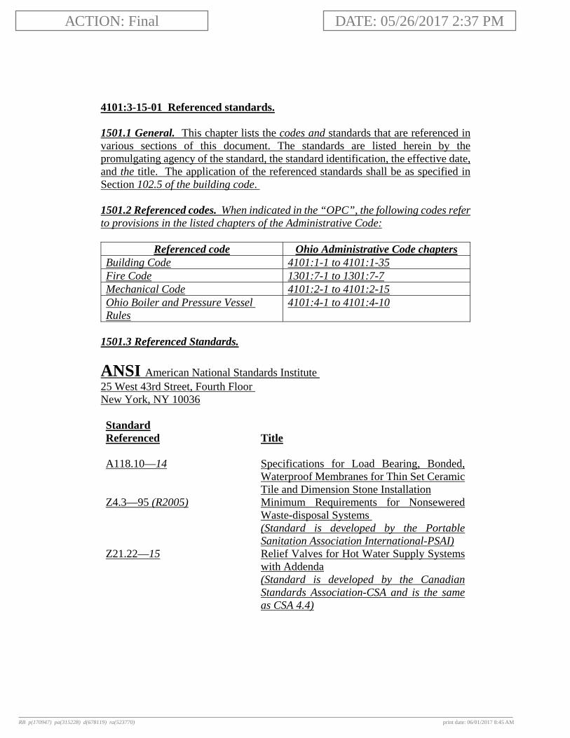
4101:3-15-01 Referenced standards. 1501.1 General. This chapter lists the codes and standards that are referenced in various sections of this document. The standards are listed herein by the promulgating agency of the standard, the standard identification, the effective date, and the title. The application of the referenced standards shall be as specified in Section 102.5 of the building code. 1501.2 Referenced codes. When indicated in the “OPC”, the following codes refer to provisions in the listed chapters of the Administrative Code:
Referenced code Ohio Administrative Code chapters Building Code 4101:1-1 to 4101:1-35 Fire Code 1301:7-1 to 1301:7-7 Mechanical Code 4101:2-1 to 4101:2-15 Ohio Boiler and Pressure Vessel Rules
4101:4-1 to 4101:4-10
1501.3 Referenced Standards.
ANSI American National Standards Institute 25 West 43rd Street, Fourth Floor New York, NY 10036 Standard Referenced
Title
A118.10—14 Specifications for Load Bearing, Bonded,
Waterproof Membranes for Thin Set Ceramic Tile and Dimension Stone Installation
Z4.3—95 (R2005) Minimum Requirements for Nonsewered Waste-disposal Systems (Standard is developed by the Portable Sanitation Association International-PSAI)
Z21.22—15 Relief Valves for Hot Water Supply Systems with Addenda (Standard is developed by the Canadian Standards Association-CSA and is the same as CSA 4.4)
ACTION: Final DATE: 05/26/2017 2:37 PM
RB p(170947) pa(315228) d(678119) ra(523770) print date: 06/01/2017 8:45 AM

4101:3-15-01 2
AHRI Air-Conditioning, Heating, & Refrigeration Institute 4100 North Fairfax Drive, Suite 200 Arlington, VA 22203 Standard Referenced
Title
1010—02 Self-contained, Mechanically Refrigerated
Drinking-Water Coolers
API American Petroleum Institute 1220 L Street NW Washington, DC 20005-4070 Standard Referenced
Title
12D—2008 Specification for Field Welded Tanks for
Storage of Production Liquids, effective April 1, 2009
12F—2008 Specification for Shop Welded Tanks for Storage of Production Liquids, effective April 1 2009
ASME American Society of Mechanical Engineers Three Park Avenue New York, NY 10016-5990 Standard Referenced
Title
A112.1.2—2012 Air Gaps in Plumbing Systems A112.1.3—2000 (R2015) Air Gap Fittings for Use with Plumbing
Fixtures, Appliances and Appurtenances A112.3.1—2007 (R2014) Stainless Steel Drainage Systems for
Sanitary, DWV, Storm and Vacuum Applications Above and Below Ground
ASME A112.3.4—2013/ CSA B45.9—2013
Macerating Toilet Systems and Related Components
A112.4.1—2009 (R2014) Water Heater Relief Valve Drain Tubes A112.4.2—2015 Water Closet Personal Hygiene Devices
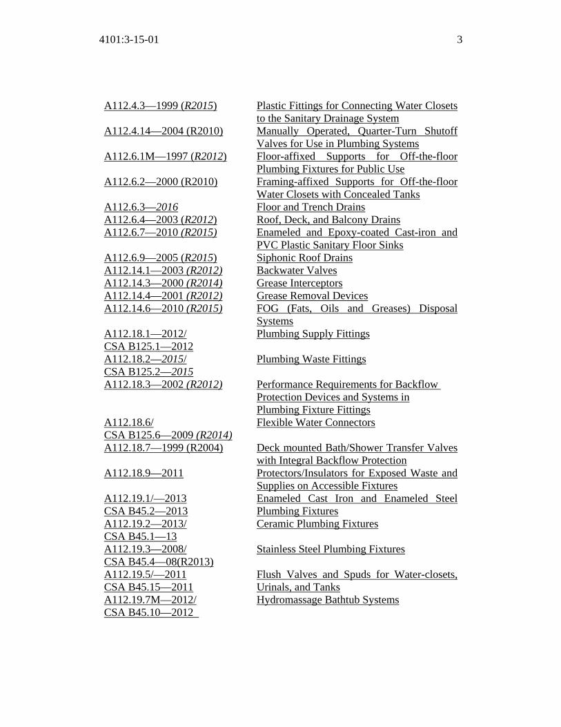
4101:3-15-01 3
A112.4.3—1999 (R2015) Plastic Fittings for Connecting Water Closets to the Sanitary Drainage System
A112.4.14—2004 (R2010) Manually Operated, Quarter-Turn Shutoff Valves for Use in Plumbing Systems
A112.6.1M—1997 (R2012) Floor-affixed Supports for Off-the-floor Plumbing Fixtures for Public Use
A112.6.2—2000 (R2010) Framing-affixed Supports for Off-the-floor Water Closets with Concealed Tanks
A112.6.3—2016 Floor and Trench Drains A112.6.4—2003 (R2012) Roof, Deck, and Balcony Drains A112.6.7—2010 (R2015) Enameled and Epoxy-coated Cast-iron and
PVC Plastic Sanitary Floor Sinks A112.6.9—2005 (R2015) Siphonic Roof Drains A112.14.1—2003 (R2012) Backwater Valves A112.14.3—2000 (R2014) Grease Interceptors A112.14.4—2001 (R2012) Grease Removal Devices A112.14.6—2010 (R2015) FOG (Fats, Oils and Greases) Disposal
Systems A112.18.1—2012/ CSA B125.1—2012
Plumbing Supply Fittings
A112.18.2—2015/ CSA B125.2—2015
Plumbing Waste Fittings
A112.18.3—2002 (R2012) Performance Requirements for Backflow Protection Devices and Systems in Plumbing Fixture Fittings
A112.18.6/ CSA B125.6—2009 (R2014)
Flexible Water Connectors
A112.18.7—1999 (R2004) Deck mounted Bath/Shower Transfer Valves with Integral Backflow Protection
A112.18.9—2011 Protectors/Insulators for Exposed Waste and Supplies on Accessible Fixtures
A112.19.1/—2013 CSA B45.2—2013
Enameled Cast Iron and Enameled Steel Plumbing Fixtures
A112.19.2—2013/ CSA B45.1—13
Ceramic Plumbing Fixtures
A112.19.3—2008/ CSA B45.4—08(R2013)
Stainless Steel Plumbing Fixtures
A112.19.5/—2011 CSA B45.15—2011
Flush Valves and Spuds for Water-closets, Urinals, and Tanks
A112.19.7M—2012/ CSA B45.10—2012
Hydromassage Bathtub Systems

4101:3-15-01 4
A112.19.12—2014 Wall Mounted and Pedestal Mounted, Adjustable, Elevating, Tilting and Pivoting Lavatory, Sink and Shampoo Bowl Carrier Systems and Drain Systems
A112.19.14-2013 Six-Liter Water Closets Equipped with a Dual Flushing Device
A112.19.15—2012 Bathtub/Whirlpool Bathtubs with Pressure Sealed Doors
A112.19.19—2006 Vitreous China Nonwater Urinals A112.21.3-1985(R2007) Hydrants for Utility and Maintenance Use A112.36.2M—1991(R2012) Cleanouts ASSE 1016/ ASME A112.1016/ CSA B125.16-2011
Performance Requirements for Individual Thermostatic, Pressure Balancing and Combination Control Valves for Individual Fixture Fittings
B1.20.1—2013 Pipe Threads, General Purpose (inch) B 16.3—2011 Malleable Iron Threaded Fittings Classes 150
and 300 B 16.4—2011 Gray Iron Threaded Fittings Classes 125 and
250 B 16.9—2012 Factory-made Wrought Steel Buttwelding
Fittings B 16.11—2011 Forged Fittings, Socket-welding and
Threaded B 16.12—2009 (R2014) Cast-iron Threaded Drainage Fittings B 16.15—2013 Cast Bronze Threaded Fittings B 16.18—2012 Cast Copper Alloy Solder Joint Pressure
Fittings B 16.22—2013 Wrought Copper and Copper Alloy Solder
Joint Pressure Fittings B 16.23—2011 Cast Copper Alloy Solder Joint Drainage
Fittings DWV B 16.26—2013 Cast Copper Alloy Fittings for Flared Copper
Tubes B 16.28—1994 Wrought Steel Buttwelding Short Radius
Elbows and Returns B 16.29—2012 Wrought Copper and Wrought Copper Alloy
Solder Joint Drainage Fittings (DWV)
B16.34—2013 Valves Flanged, Threaded and Welding End B16.51—2013 Copper and Copper Alloy Press-Connect

4101:3-15-01 5
Pressure Fittings BPVC Section IX-the edition referenced in rule 4101:4-3-01 of the Administrative Code
Welding and Brazing Qualifications
ASPE American Society of Plumbing Engineers 8614 Catalpa Avenue, Suite 1007 Chicago, IL 60656-1116 Standard Referenced
Title
45—2013 Siphonic Roof Drainage Systems
ASSE American Society of Sanitary Engineering 901 Canterbury Road, Suite A Westlake, OH 44145 Standard Referenced
Title
1001—2008 Performance Requirements for Atmospheric Type Vacuum Breakers
1002—2015 Performance Requirements for Antisiphon Fill Valves (Ballcocks) for Gravity Water Closet Flush Tanks
1003—2009 Performance Requirements for Water Pressure Reducing Valves
1004—2008 Performance Requirements for Backflow Prevention Requirements for Commercial Dishwashing Machines
1005—1999 Performance Requirements for Water Heater Drain Valves
1008—2006 Performance Requirements for Plumbing Aspects of Food Waste Disposer Units
1010—2004 Performance Requirements for Water Hammer Arresters
1011—2004 Performance Requirements for Hose Connection Vacuum Breakers
1012—2009 Performance Requirements for Backflow Preventers with Intermediate

4101:3-15-01 6
Atmospheric Vent 1013—2011 Performance Requirements for Reduced
Pressure Principle Backflow Preventers and Reduced Pressure Principle Fire Protection Backflow Preventers
1015—2011 Performance Requirements for Double Check Backflow Prevention Assemblies and Double Check Fire Protection Backflow Prevention Assemblies
ASSE 1016/ ASME A112.1016/ CSA B125.16—2011
Performance Requirements for Individual Thermostatic, Pressure Balancing and Combination Control Valves for Individual Fixture Fittings
1017—2010 Performance Requirements for Temperature Actuated Mixing Valves for Hot Water Distribution Systems
1018—2010 Performance Requirements for Trap Seal Primer Valves; Potable Water Supplied
1019—2011 Performance Requirements for Vacuum Breaker Wall Hydrants, Freeze Resistant, Automatic Draining Type
1020—2004 Performance Requirements for Pressure Vacuum Breaker Assembly
1022—2003 Performance Requirements for Backflow Preventer for Beverage Dispensing Equipment
1024—2004 Performance Requirements for Dual Check Valve Type Backflow Preventers (for Residential Supply Service or Individual Outlets)
1035—2008 Performance Requirements for Laboratory Faucet Backflow Preventers
1037—2015 Performance Requirements for Pressurized Flushing Devices for Plumbing Fixtures
1044—2015 Performance Requirements for Trap Seal Primer Devices Drainage Types and Electronic Design Types
1047—2011 Performance Requirements for Reduced Pressure Detector Fire Protection Backflow Prevention Assemblies
1048—2011 Performance Requirements for Double

4101:3-15-01 7
Check Detector Fire Protection Backflow Prevention Assemblies
1049—2009 Performance Requirements for Individual and Branch Type Air Admittance Valves for Chemical Waste Systems
1050—2009 Performance Requirements for Stack Air Admittance Valves for Sanitary Drainage Systems
1051—2009 Performance Requirements for Individual and Branch Type Air Admittance Valves for Sanitary Drainage Systems-fixture and Branch Devices
1052—2016 Performance Requirements for Hose Connection Backflow Preventers
1055—2009 Performance Requirements for Chemical Dispensing Systems
1056—2013 Performance Requirements for Spill Resistant Vacuum Breaker
1060—2006 Performance Requirements for Outdoor Enclosures for Fluid Conveying Components
1061—2015 Performance Requirements for Removable and Nonremovable Push Fit Fittings
1062—2006 Performance Requirements for Temperature Actuated, Flow Reduction Valves to Individual Supply Fittings
1066—2009 Performance Requirements for Individual Pressure Balancing In-line Valves for Individual Fixture Fittings
1069—2005 Performance Requirements for Automatic Temperature Control Mixing Valves
1070—2015 Performance Requirements for Water-temperature Limiting Devices
1072—2007 Performance Requirements for Barrier Type Floor Drain Tap Seal Protection Devices
1079—2012 Performance Requirements for Dielectric Pipe Unions
5013—2015 Performance Requirements for Testing Reduced Pressure Principle Backflow Prevention Assembly (RPA) and Reduced Pressure Fire Protection Backflow Preventers (RFP)

4101:3-15-01 8
5015—2015 Performance Requirements for Testing Double Check Valve Backflow Prevention Assemblies (DC) and Double Check Fire Protection Backflow Prevention Assemblies (DCF)
5020—2015 Performance Requirements for Testing Pressure Vacuum Breaker Assemblies (PVBA)
5047—2015 Performance Requirements for Testing Reduced Pressure Detector Fire Protection Backflow Prevention Assemblies (RPDA)
5048—2015 Performance Requirements for Testing Double Check Valve Detector Assembly (DCDA)
5052—2015 Performance Requirements for Testing Hose Connection Backflow Preventers
5056—2015 Performance Requirements for Testing Spill Resistant Vacuum Breaker (SRVB)
ASTM ASTM International 100 Barr Harbor Drive West Conshohocken, PA 19428-2959 Standard Referenced
Title
A 53/A 53M—12 Specification for Pipe, Steel, Black and Hot-
dipped, Zinc-coated Welded and Seamless
A 74—16 Specification for Cast-iron Soil Pipe and Fittings
A 312/A 312M—16 Specification for Seamless, Welded, And Heavily Cold Worked Austenitic Stainless Steel Pipes
A 733—15 Specification for Welded and Seamless Carbon Steel and Austenitic Stainless Steel Pipe Nipples
A 778—16 Specification for Welded Unannealed Austenitic Stainless Steel Tubular Products
A 888—15 Specification for Hubless Cast-iron Soil Pipe

4101:3-15-01 9
and Fittings for Sanitary and Storm Drain, Waste, and Vent Piping Application
B 32—08 (2014) Specification for Solder Metal B 42—15a Specification for Seamless Copper Pipe,
Standard Sizes B 43—15 Specification for Seamless Red Brass Pipe,
Standard Sizes B 75—11 Specification for Seamless Copper Tube B 88—14 Specification for Seamless Copper Water
Tube B 152/B 152M—13 Specification for Copper Sheet, Strip Plate
and Rolled Bar B 251—10 Specification for General Requirements for
Wrought Seamless Copper and Copper-alloy Tube
B 302—12 Specification for Threadless Copper Pipe, Standard Sizes
B 306—13 Specification for Copper Drainage Tube (DWV)
B 447—12a Specification for Welded Copper Tube B 687—99(2016) Specification for Brass, Copper and
Chromium-plated Pipe Nipples B 813—16 Specification for Liquid and Paste Fluxes for
Soldering of Copper and Copper Alloy Tube
B 828—16 Practice for Making Capillary Joints by Soldering of Copper and Copper Alloy Tube and Fittings
C 4—04(2014) Specification for Clay Drain Tile and Perforated Clay Drain Tile
C 14—15a Specification for Nonreinforced Concrete Sewer, Storm Drain and Culvert Pipe
C 76—15a Specification for Reinforced Concrete Culvert, Storm Drain and Sewer Pipe
C 425—04(2013) Specification for Compression Joints for Vitrified Clay Pipe and Fittings
C 443—12 Specification for Joints for Concrete Pipe and Manholes, Using Rubber Gaskets.
C 564—14 Specification for Rubber Gaskets for Cast-iron Soil Pipe and Fittings

4101:3-15-01 10
C 700—13 Specification for Vitrified Clay Pipe, Extra Strength, Standard Strength, and Perforated
C 1053—00(2015) Specification for Borosilicate Glass Pipe and Fittings for Drain, Waste, and Vent (DWV) Applications
C 1173—10(2014) Specification for Flexible Transition Couplings for Underground Piping System
C 1277—13 Specification for Shielded Coupling Joining Hubless Cast-iron Soil Pipe and Fittings
C 1440—08(2013) Specification for Thermoplastic Elastomeric (TPE) Gasket Materials for Drain, Waste, and Vent (DWV), Sewer, Sanitary and Storm Plumbing Systems
C 1460—12 Specification for Shielded Transition Couplings for Use with Dissimilar DWV Pipe and Fittings Above Ground
C 1461—08 (2013) Specification for Mechanical Couplings Using Thermoplastic Elastomeric (TPE) Gaskets for Joining Drain, Waste and Vent (DWV) Sewer, Sanitary and Storm Plumbing Systems for Above and Below Ground Use
C 1540—15 Specification for Heavy Duty Shielded Couplings Joining Hubless Cast-iron Soil Pipe and Fittings
C 1563—13 Standard Test Method for Gaskets for Use in Connection with Hub and Spigot Cast Iron Soil Pipe and Fittings for Sanitary Drain, Waste, Vent and Storm Piping Applications
D 1253—14 Standard Test Method For Residual Chlorine in Water
D 1527—99(2005) Specification for Acrylonitrile-Butadiene-Styrene (ABS) Plastic Pipe, Schedules 40 and 80
D 1785—15 Specification for Poly (Vinyl Chloride) (PVC) Plastic Pipe, Schedules 40, 80 and 120
D 2235—04(2011) Specification for Solvent Cement for Acrylonitrile-Butadiene-Styrene (ABS) Plastic Pipe and Fittings
D 2239—12a Specification for Polyethylene (PE) Plastic

4101:3-15-01 11
Pipe (SIDR-PR) Based on Controlled Inside Diameter
D 2241—15 Specification for Poly (Vinyl Chloride) (PVC) Pressure-rated Pipe (SDR-Series)
D 2282—99(2005) Specification for Acrylonitrile-Butadiene-Styrene (ABS) Plastic Pipe (SDR-PR)
D 2464—15 Specification for Threaded Poly (Vinyl Chloride) (PVC) Plastic Pipe Fittings, Schedule 80
D 2466—15 Specification for Poly (Vinyl Chloride) (PVC) Plastic Pipe Fittings, Schedule 40
D 2467—15 Specification for Poly (Vinyl Chloride) (PVC) Plastic Pipe Fittings, Schedule 80
D 2468—96a Specification for Acrylonitrile-Butadiene-Styrene (ABS) Plastic Pipe Fittings, Schedule 40
D 2564—12 Specification for Solvent Cements for Poly (Vinyl Chloride) (PVC) Plastic Piping Systems
D 2609—15 Specification for Plastic Insert Fittings for Polyethylene (PE) Plastic Pipe
D 2657—15 Practice for Heat Fusion-joining of Polyolefin Pipe and Fitting Waste, and Vent Pipe and Fittings
D 2661—14 Specification for Acrylonitrile-Butadiene-Styrene (ABS) Schedule 40 Plastic Drain, Waste, and Vent Pipe and Fittings
D 2665—14 Specification for Poly (Vinyl Chloride) (PVC) Plastic Drain, Waste, and Vent Pipe and Fittings
D 2672—14 Specification for Joints for IPS PVC Pipe Using Solvent Cement
D 2683—14 Standard Specification for Socket-type Polyethylene fittings for Outside Diameter-controlled Polyethylene Pipe and Tubing
D 2729—11 pecification for Poly (Vinyl Chloride) (PVC) Sewer Pipe and Fittings
D 2737—2012a Specification for Polyethylene (PE) Plastic Tubing.
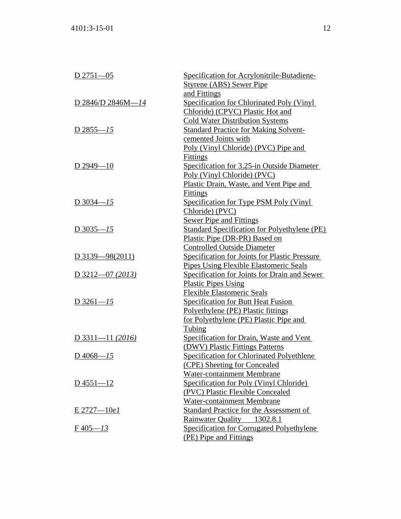
4101:3-15-01 12
D 2751—05 Specification for Acrylonitrile-Butadiene-Styrene (ABS) Sewer Pipe and Fittings
D 2846/D 2846M—14 Specification for Chlorinated Poly (Vinyl Chloride) (CPVC) Plastic Hot and Cold Water Distribution Systems
D 2855—15 Standard Practice for Making Solvent-cemented Joints with Poly (Vinyl Chloride) (PVC) Pipe and Fittings
D 2949—10 Specification for 3.25-in Outside Diameter Poly (Vinyl Chloride) (PVC) Plastic Drain, Waste, and Vent Pipe and Fittings
D 3034—15 Specification for Type PSM Poly (Vinyl Chloride) (PVC) Sewer Pipe and Fittings
D 3035—15 Standard Specification for Polyethylene (PE) Plastic Pipe (DR-PR) Based on Controlled Outside Diameter
D 3139—98(2011) Specification for Joints for Plastic Pressure Pipes Using Flexible Elastomeric Seals
D 3212—07 (2013) Specification for Joints for Drain and Sewer Plastic Pipes Using Flexible Elastomeric Seals
D 3261—15 Specification for Butt Heat Fusion Polyethylene (PE) Plastic fittings for Polyethylene (PE) Plastic Pipe and Tubing
D 3311—11 (2016) Specification for Drain, Waste and Vent (DWV) Plastic Fittings Patterns
D 4068—15 Specification for Chlorinated Polyethlene (CPE) Sheeting for Concealed Water-containment Membrane
D 4551—12 Specification for Poly (Vinyl Chloride) (PVC) Plastic Flexible Concealed Water-containment Membrane
E 2727—10e1 Standard Practice for the Assessment of Rainwater Quality 1302.8.1
F 405—13 Specification for Corrugated Polyethylene (PE) Pipe and Fittings

4101:3-15-01 13
F 409—12 Specification for Thermoplastic Accessible and Replaceable Plastic Tube and Tubular Fittings
F 437—15 Specification for Threaded Chlorinated Poly (Vinyl Chloride) (CPVC) Plastic Pipe Fittings, Schedule 80
F 438—15 Specification for Socket-type Chlorinated Poly (Vinyl Chloride) (CPVC) Plastic Pipe Fittings, Schedule 40
F 439—13 Standard Specification for Chlorinated Poly (Vinyl Chloride) (CPVC) Plastic Pipe Fittings, Schedule 80
F 441/F 441M—15 Specification for Chlorinated Poly (Vinyl Chloride) (CPVC) Plastic Pipe, Schedules 40 and 80
F 442/F 442M—13e1 Specification for Chlorinated Poly (Vinyl Chloride) (CPVC) Plastic Pipe (SDR-PR)
F 477—14 Specification for Elastomeric Seals (Gaskets) for Joining Plastic Pipe
F 493—14 Specification for Solvent Cements for Chlorinated Poly (Vinyl Chloride) (CPVC) Plastic Pipe and Fittings
F 628—12e2 Specification for Acrylonitrile-Butadiene-Styrene (ABS) Schedule 40 Plastic Drain, Waste, and Vent Pipe with a Cellular Core
F 656—15 Specification for Primers for Use in Solvent Cement Joints of Poly (Vinyl Chloride) (PVC) Plastic Pipe and Fittings
F 714—2013 Specification for Polyethylene (PE) Plastic Pipe (SDR-PR) Based on Outside Diameter
F 876—15a Specification for Cross-linked Polyethylene (PEX) Tubing
F 877—2011a Specification for Cross-linked Polyethylene (PEX) Plastic Hot and Cold Water Distribution Systems
F 891—10 Specification for Coextruded Poly (Vinyl Chloride) (PVC) Plastic Pipe with a Cellular Core

4101:3-15-01 14
F 1055—15 Standard Specification for Electrofusion Type Polyethylene Fittings for Outside Diameter Controlled Polyethylene and Crosslinked Polyethylene Pipe and Tubing
F 1281—11 Specification for Cross-linked Polyethylene/Aluminum/ Cross-linked Polyethylene (PEX-AL-PEX) Pressure Pipe
F 1282—10 Specification for Polyethylene/Aluminum/Polyethylene (PE-AL-PE) Composite Pressure Pipe
F 1412—16 Specification for Polyolefin Pipe and Fittings for Corrosive Waste Drainage
F 1476—13 Standard Specification for Performance of Gasketed Mechanical Couplings for Use in Piping Applications
F 1488—14 Specification for Coextruded Composite PipeF 1548—01(2012) Standard Specification for the Performance
of Fittings for Use with Gasketed Mechanical Couplings Used in Piping Applications
F 1673—10 Polyvinylidene Fluoride (PVDF) Corrosive Waste Drainage Systems
F 1807—15 Specification for Metal Insert Fittings Utilizing a Copper Crimp Ring for SDR9 Cross-linked Polyethylene (PEX) Tubing and SDR9 Polyethylene of Raised Temperature (PE-RT) Tubing
F 1866—13 Specification for Poly (Vinyl Chloride) (PVC) Plastic Schedule 40 Drainage and DWV Fabricated Fittings
F 1960—15 Specification for Cold Expansion Fittings with PEX Reinforcing Rings for use with Cross-linked Polyethylene (PEX) Tubing
F 1970—12e1 Special Engineered Fittings, Appurtenances or Valves for use in Poly (Vinyl Chloride) (PVC) OR Chlorinated Poly (Vinyl Chloride) (CPVC) Systems
F 1974—15 Specification for Metal Insert Fittings for Polyethylene/Aluminum/Polyethylene and Cross-linked Polyethylene/Aluminum/Cross-

4101:3-15-01 15
linked Polyethylene Composite Pressure Pipe
F 1986—01(2011) Specification for Multilayer Pipe, Type 2, Compression Fittings and Compression Joints for Hot and Cold Drinking Water Systems
F 2080—15a Specifications for Cold-expansion Fittings with Metal Compression-sleeves for Cross-linked Polyethylene (PEX) Pipe
F 2098—15 Standard specification for Stainless Steel Clamps for Securing SDR9 Cross-linked Polyethylene (PEX) Tubing to Metal and Plastic Insert Fittings
F 2159—14 Specification for Plastic Insert Fittings Utilizing a Copper Crimp Ring for SDR9 Cross-linked Polyethylene (PEX) Tubing and SDR9 Polyethylene of Raised Temperature (PE-RT) Tubing
F 2262—09 Specification for Cross-linked Polyethylene/Aluminum/Cross-linked Polyethylene Tubing OD Controlled SDR9
F 2306/F 2306M—14e1 12'' to 60'' Annular Corrugated Profile-wall Polyethylene (PE) Pipe and Fittings for Gravity Flow Storm Sewer and Subsurface Drainage Applications
F 2389—15 Specification for Pressure-rated Polypropylene (PP) Piping Systems
F 2434—14 Standard Specification for Plastic Insert Fittings Utilizing a Copper Crimp Ring for SDR9 Cross-linked Polyethylene (PEX) Tubing and SDR9 Cross-linked Polyethylene/Aluminum/ Cross-linked Polyethylene (PEX AL-PEX) Tubing
F 2735—09 Standard Specification for Plastic Insert Fittings for SDR9 Cross-linked Polyethylene (PEX) and Polyethylene of Raised Temperature (PE-RT) Tubing
F 2769—14 Polyethylene or Raised Temperature (PE-RT) Plastic Hot and Cold Water Tubing and Distribution Systems
F 2831—12 Standard Practice for Internal Non Structural

4101:3-15-01 16
Epoxy Barrier Coating Material Used In Rehabilitation of Metallic Pressurized Piping Systems
F 2855—12 Specification Poly (Vinyl Chloride)/Aluminum/Poly (Vinyl Chloride) (CPVC/AL/CPVC) Composite Pressure Tubing
AWS American Welding Society 8669 NW 36 Street, #130 Doral, FL 33166 Standard Referenced
Title
A5.8M/A5.8—2011 Specifications for Filler Metals for Brazing
and Braze Welding
AWWA American Water Works Association 6666 West Quincy Avenue Denver, CO 80235 Standard Referenced
Title
C104/A21.4-13 Cement-mortar Lining for Ductile-iron Pipe
and Fittings for Water C110/A21.10—12 Ductile-iron and Gray-iron Fittings C111/A21.11-12 Rubber-gasket Joints for Ductile-iron
Pressure Pipe and Fittings C115/A21.15—11 Flanged Ductile-iron Pipe with Ductile-iron
or Gray-iron Threaded Flanges C151/A21.51—09 Ductile-iron Pipe, Centrifugally Cast for
Water C153—00/A21.53—11 Ductile-iron Compact Fittings for Water
Service C500—09 Standard for Metal-Seated Gate Valves for
Water Supply Service C504—15 Standard for Rubber-Seated Butterfly Valves C507—15 Standard for Ball Valves, 6 In. Through 60 In.

4101:3-15-01 17
C510—07 Double Check Valve Backflow Prevention Assembly
C511—07 Reduced-pressure Principle Backflow Prevention Assembly
C651—14 Disinfecting Water Mains C652—11 Disinfection of Water-storage Facilities C901—08 Polyethylene (PE) Pressure Pipe and Tubing
1/ inch (13 mm) Through 3 inch (76 mm) for Water Service.
C904—16 Cross-linked Polyethylene (PEX) Pressure Pipe 1/ inch (13 mm) Through 3 inch (76 mm) for Water Service
D100—11 Standard for Welded Carbon Steel Tanks for Water Storage
D115—06 Standard for Tendon Prestressed-Concrete Water Tanks
D120—09 Standard for Thermosetting Fiberglass-Reinforced Plastic Tanks
CISPI Cast Iron Soil Pipe Institute 5959 Shallowford Road, Suite 419 Chattanooga, TN 37421 Standard Referenced
Title
301—12 Specification for Hubless Cast-iron Soil Pipe
and Fittings for Sanitary and Storm Drain, Waste and Vent Piping Applications
310—12 Specification for Coupling for Use in Connection with Hubless Cast-iron Soil Pipe and Fittings for Sanitary and Storm Drain, Waste and Vent Piping Applications
CSA CSA Group 8501 East Pleasant Valley Cleveland, OH 44131-5516 Standard Referenced
Title

4101:3-15-01 18
A257.1M—2012 Circular Concrete Culvert, Storm Drain,
Sewer Pipe and Fittings A257.2M—2012 Reinforced Circular Concrete Culvert, Storm
Drain, Sewer Pipe and Fittings A257.3M—2012 Joints for Circular Concrete Sewer and
Culvert Pipe, Manhole Sections and Fittings Using Rubber Gaskets
ASME A112.18.1—2012/ CSA B125.1—2012
Plumbing Supply Fittings
A112.18.2—2015/ CSA B125.2—2015
Plumbing Waste Fittings
ASME A112.19.2—2013/ B45.1—2013
Ceramic Plumbing Fixtures
ASME A112.19.1—2013/ CSA B45.2—2013
Enameled Cast-iron and Enameled Steel Plumbing Fixtures
ASME A112.19.3—2008/ CSA B45.4—08(R2013)
Stainless-steel Plumbing Fixtures
ASME A112.19.5—2011/ CSA B45.15—2011
Flush Valves and Spuds for Water Closets, Urinals and Tanks
ASME A112.19.7—2012/ CSA B45.10—2012
Hydromassage Bathtub Systems
CSA B45.5—11(R2016)/ IAPMO Z124-2011(R2016)
Plastic Plumbing Fixtures
ASME A112.3.4—2013/ CSA B45.9—2013
Macerating Systems and Related Components
CSA B125.16—2011 Performance Requirements for Individual Thermostatic, Pressure Balancing and Combination Control Valves for Individual Fixture Fittings
B64.1.1—11 (2016) Vacuum Breakers, Atmospheric Type (AVB) B64.1.2—11 (2016) Pressure Vacuum Breakers, (PVB) B64.1.3—11 (2016) Spill Resistant Pressure Vacuum Breaks
(SRPVB) B64.2—11 (2016) Vacuum Breakers, Hose Connection Type
(HCVB) B64.2.1—11 (2016) Vacuum Breakers, Hose Connection
(HCVB) with Manual Draining Feature B64.2.1.1—11 (2016) Hose Connection Dual Check Vacuum
Breakers, (HCDVB) B64.2.2—11 (2016) Vacuum Breakers, Hose Connection Type

4101:3-15-01 19
(HCVB) with Automatic Draining Feature
B64.3—11 (2016) Backflow Preventers, Dual Check Valve Type with Atmospheric Port (DCAP)
B64.4—11 (2016) Backflow Preventers, Reduced Pressure Principle Type (RP)
B64.4.1—11 (2016) Reduced Pressure Principle for Fire Sprinklers (RPF)
B64.5—11 (2016) Double Check Backflow Preventers (DCVA) B64.5.1—11 (2016) Double Check Valve Backflow Preventer for
Fire Systems (DCVAF) B64.6—11 (2016) Dual Check Backflow PreventersValve
(DuC) B64.7—11 (2016) Laboratory Faucet Vacuum Breakers
(LFVB) B64.10—11 (2016) Manual for the Selection and Installation of
Backflow Prevention Devices B64.10.1—11 (2016) Maintenance and Field Testing of Backflow
Preventers B79—08(R2013) Commercial and Residential Drains, and
Cleanouts B125.3—2012 Plumbing Fittings B137.1—13 Polyethylene (PE) Pipe, Tubing and Fittings
for Cold Water Pressure Services B137.2—13 Polyvinylchloride PVC Injection-moulded
Gasketed Fittings for Pressure Applications B137.3—13 Rigid Poly (Vinyl Chloride) (PVC) Pipe for
Pressure Applications B137.5—13 Cross-linked Polyethylene (PEX) Tubing
Systems for Pressure Applications B137.6—13 CPVC Pipe, Tubing and Fittings for Hot and
Cold Water Distribution Systems B137.9—13 Polyethylene/Aluminum/
Polyethylene Composite Pressure Pipe Systems
B137.10—13 Cross-linked Polyethylene/Aluminum/ Polyethylene Composite Pressure Pipe Systems
B137.11—13 Polypropylene (PP-R) Pipe and Fittings for Pressure Applications
B181.1—15 Acrylonitrile-butadiene-styrene ABS Drain,

4101:3-15-01 20
Waste and Vent Pipe and Pipe Fittings B 181.2—15 Polyvinylchloride PVC and chlorinated
polyvinylchloride (CPVC) Drain, Waste, and Vent Pipe and Pipe Fittings
B 181.3—15 Polyolefin and Polyvinylidene Fluoride (PVDF) Laboratory Drainage Systems
B182.1—15 Plastic Drain and Sewer Pipe and Pipe Fittings
B182.2—15 PSM Type Polyvinylchloride PVC Sewer Pipe and Fittings
B182.4—15 Profile Polyvinylchloride PVC Sewer Pipe and Fittings
B182.6—15 Profile Polyethylene (PE) Sewer Pipe and Fittings for Leak-proof Sewer Applications
B182.8—15 Profile Polyethylene (PE) Storm Sewer and Drainage Pipe and Fittings
B356—10 (R2015) Water Pressure Reducing Valves for Domestic Water Systems
B483.1—14 Drinking Water Treatment Units B481.1—12 Testing and Rating of Grease interceptors
Using Lard B481.3—12 Sizing, Selection, Location and Installation
of Grease Interceptors B602—16 Mechanical Couplings for Drain, Waste and
Vent Pipe and Sewer Pipe
FEMA Federal Emergency Management Agency Federal Center Plaza 500 C Street S.W. Washington, DC 20472 Standard Referenced
Title
44 CFR Parts 59-77 (2002) National Flood Insurance Program
IAPMO IAPMO Group 4755 E. Philadelphia Ontario, CA 91761
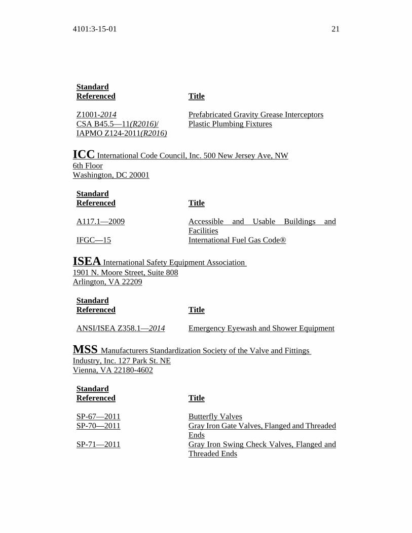
4101:3-15-01 21
Standard Referenced
Title
Z1001-2014 Prefabricated Gravity Grease Interceptors CSA B45.5—11(R2016)/ IAPMO Z124-2011(R2016)
Plastic Plumbing Fixtures
ICC International Code Council, Inc. 500 New Jersey Ave, NW 6th Floor Washington, DC 20001 Standard Referenced
Title
A117.1—2009 Accessible and Usable Buildings and
Facilities IFGC—15 International Fuel Gas Code®
ISEA International Safety Equipment Association 1901 N. Moore Street, Suite 808 Arlington, VA 22209 Standard Referenced
Title
ANSI/ISEA Z358.1—2014 Emergency Eyewash and Shower Equipment
MSS Manufacturers Standardization Society of the Valve and Fittings Industry, Inc. 127 Park St. NE Vienna, VA 22180-4602 Standard Referenced
Title
SP-67—2011 Butterfly Valves SP-70—2011 Gray Iron Gate Valves, Flanged and Threaded
Ends SP-71—2011 Gray Iron Swing Check Valves, Flanged and
Threaded Ends
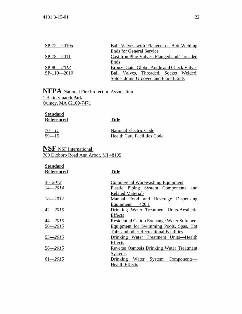
4101:3-15-01 22
SP-72—2010a Ball Valves with Flanged or Butt-Welding Ends for General Service
SP-78—2011 Cast Iron Plug Valves, Flanged and Threaded Ends
SP-80—2013 Bronze Gate, Globe, Angle and Check ValvesSP-110—2010 Ball Valves, Threaded, Socket Welded,
Solder Joint, Grooved and Flared Ends
NFPA National Fire Protection Association 1 Batterymarch Park Quincy, MA 02169-7471 Standard Referenced
Title
70—17 National Electric Code 99—15 Health Care Facilities Code
NSF NSF International 789 Dixboro Road Ann Arbor, MI 48105 Standard Referenced
Title
3—2012 Commercial Warewashing Equipment 14—2014 Plastic Piping System Components and
Related Materials 18—2012 Manual Food and Beverage Dispensing
Equipment 426.1 42—2015 Drinking Water Treatment Units-Aesthetic
Effects 44—2015 Residential Cation Exchange Water Softeners50—2015 Equipment for Swimming Pools, Spas, Hot
Tubs and other Recreational Facilities 53—2015 Drinking Water Treatment Units—Health
Effects 58—2015 Reverse Osmosis Drinking Water Treatment
Systems 61—2015 Drinking Water System Components—
Health Effects

4101:3-15-01 23
62—2015 Drinking Water Distillation Systems 350—2014 Onsite Residential and Commercial Water
Reuse Treatment Systems 359—2011 Valves for Crosslinked Polyethylene (PEX)
Water Distribution Tubing Systems 372—2016 Drinking Water Systems Components—Lead
Content
PDI Plumbing and Drainage Institute 800 Turnpike Street, Suite 300 North Andover, MA 01845 Standard Referenced
Title
PDI G101- 2015 Testing and Rating Procedure for Grease
Interceptors with Appendix of Sizing and Installation Data
PDI G102- 2009 Testing and Certification for Grease Interceptors with Fog Sensing and Alarm Devices
UL UL LLC 333 Pfingsten Road Northbrook, IL 60062-2096 Standard Referenced
Title
399—2008 Drinking-Water Coolers—with revisions
through January 14, 2011 430—2015 Waste Disposers 508—99 Industrial Control Equipment—with revisions
through March 2013 1795—2009 Hydromassage Bathtubs including revisions
through August 23, 2011

Replaces: 4101:3-13-01
Effective: 11/01/2017
Five Year Review (FYR) Dates: 11/01/2022
CERTIFIED ELECTRONICALLY
Certification
05/26/2017
Date
Promulgated Under: 119.03Statutory Authority: 3781.10(A)Rule Amplifies: 3781.10, 3781.11, 3791.04Prior Effective Dates: 3/1/98, 4/1/99, 12/1/00, 1/1/02, 1/1/04, 3/1/05, 9/6/05,
3/1/06, 7/1/07, 1/1/08, 3/31/08(Emer.), 6/24/08,1/1/09, 11/1/11, 3/1/13, 7/1/14, 1/1/15, 1/1/16
4101:3-15-01 24

Summary of BBS Proposed Ohio Plumbing Code Rule Changes – October 2016
Ohio Administrative Code Rule Number
OPC Section IPC change origin Reason for proposed change
4101:3-2-01 Alternate on-site nonpotable water
2015 Added definition
Backflow preventer 2015 Modified definition Collection pipe 2015 Added definition Demand recirculation
water system 2015 Added definition
Design flood elevation 2015 Modified definition Drinking fountain 2015 Added definition Grease interceptor 2012 Break out definition
into two types: Hydro-mechanical and Gravity
Grease interceptor 2015 Adds another type: Fats, oils and greases (FOG) disposal system
Mechanical joint 2015 Modifies definition Meter 2015 Adds definition On-site nonpotable water
reuse system 2015 Adds definition
Plumbing system 2015 Modifies definition Rainwater 2015 Adds definition Reclaimed water 2015 Adds definition Sewer, Public sewer 2015 Modifies definition Storm water 2015 Adds definition Toilet facility 2015 Adds definition Water cooler 2015 Adds definition Water dispenser 2015 Adds definition 4101:3-3-01 304.4 2012 Clarifies how the
annular space between pipes and structures is to be sealed for the purpose of rodent-proofing
305.4 BBS initiated change
Removes the methods for freeze protection
307.5 2015 Adds a new section for protection of footings
Table 308.5 2012 Add PE-RT to the table Table 308.5 note b 2015 Clarifies meaning of
midstory guide 309.2 2012 Clarifies flood hazard
design intent 310.2 2012 Relocated compartment
and partition

requirements to OPC section 405
312.2.2 BBS initiated change
Clarified that the intent of the requirement was to have dual pressure relief valves, not one device
314.2.4.1 2015 Adds an in-line check valve requirement for ductless mini-split system condensate lines or traps
314.2.5 2015 Adds a new section for condensate line cleanouts
315 2012 Added a new section to address pipe penetrations
316 2012 Adds a reference to chapter 1 for alternative engineered design
4101:3-4-01 403.3 2012 Adds an exception for public toilet facilities in open or enclosed parking garages and exempts toilet facilities where there are no parking attendants
403.3 2015 Modifies the parking garage exception and adds an additional exception for public toilet facilities
403.3.4 2012 Adds open malls to the section
403.3.6 2012 Adds a new section for door locking
404.2 2015 Creates a new section by splitting up 404.1
404.3 2015 Relocated the requirement for drain pipe covering
405.3 2012 Relocates compartment and partition requirements from OPC Chapter 3
405.4 2012 Clarifies fixture floor connections

406.1 2012 Deletes the standard for domestic clothes washers
406.1 2015 Adds standards for air gaps integral to the washing machine
406.2 2012 Clarifies drainage requirements for automatic clothes washers
407.2 2012 Requires an overflow outlet for bathtubs
409.1 2012 Removes standard for domestic dishwashing machines
409.2 2015 Adds standards for air gaps integral to the dishwashing machine
410.1 2015 Adds a standard for drinking water coolers
410.2 2015 Adds a drinking fountain exception for small occupancies
410.3 2015 Adds a requirement and exception for high and low drinking fountains
410.4 2012 and modified by BBS
Adds a section for drinking fountain substitution
413 2015 Changes “grinder” to “disposer” and requires listing and labeling in accordance with UL 430
413.2 2015 Changes “grinder” to “disposer”
413.3 2015 Changes “grinder” to “disposer”
413.4 2015 Changes “grinder” to “disposer”
415.1 2015 Updates standards 416.1 2015 Updates standards 416.2 2015 Updates standards 417.1 2015 Updates standards 417.4.1 2015 Extends watertight
requirements to floor areas
418.1 2015 Updates standards 419.1 2015 Updates standards

420.1 2015 Updates standards and recognizes dual flushing devices
421.1 2015 Updates standards and requires listing and labeling
423.3 2015 Adds a section addressing footbaths, pedicure baths, and shampoo sinks
424.3 2015 Updates standards 424.4 2015 Updates standards
424.8 2015 Updates standards 4101:3-5-01 501.3 2015 Removes reference to
ASSE 1005 and prescribes the size of the drain valve inlet
504.4.1 2012 Clarifies that the temperature and pressure relief valve is also required on separate water storage tanks
504.6 2015 Adds a minimum distance from the floor or flood level rim of the waste receptor
504.7 2012 Clarifies that the section applies to storage tank-type water heaters, not tankless-type water heaters
504.7.2 2015 Clarifies that pan drains are not required on water heater replacements
4101:3-6-01 601.5 2015 Adds a section addressing epoxy lining systems
Table 604.3 2015 Modifies flow rate and pressure for lavatories, sinks, shower
Table 604.5, note a 2015 Modified the developed length from 60 feet to 50 feet
Tables 605.3 and 605.4 2015 Adds CPVC/AL/CPVC pipe
Table 605.5 2015 Updates standards 605.7 2015 Clarifies valve
requirements
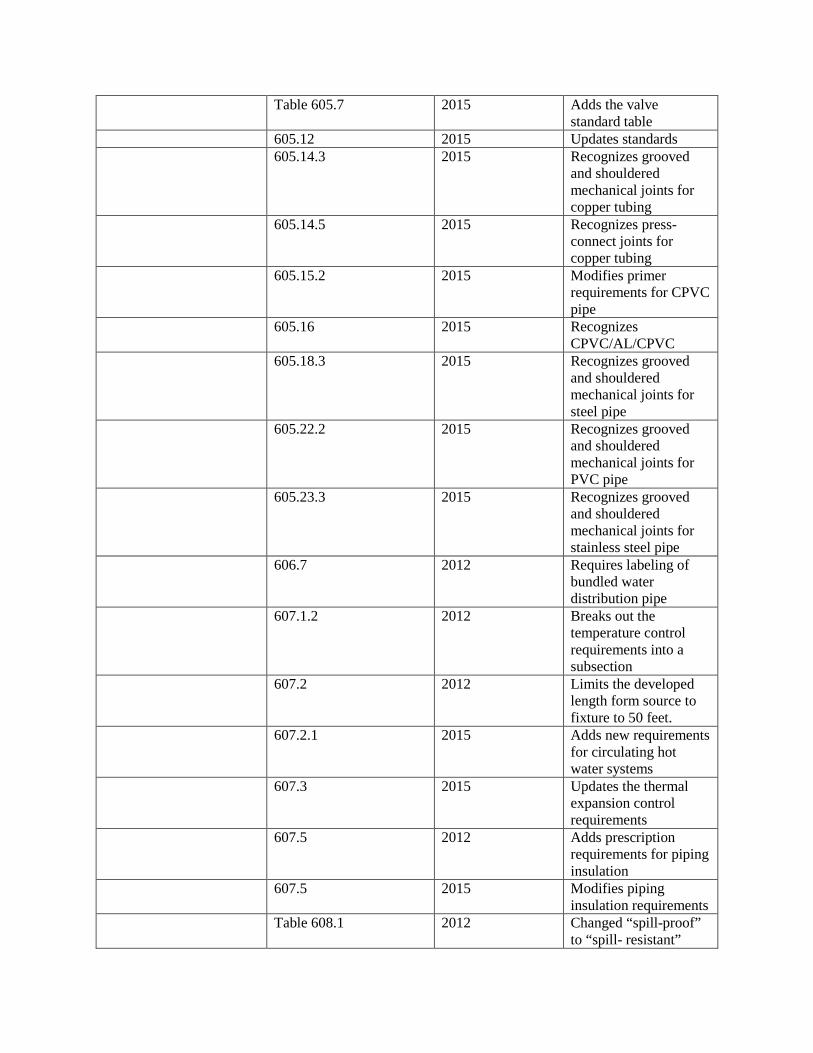
Table 605.7 2015 Adds the valve standard table
605.12 2015 Updates standards 605.14.3 2015 Recognizes grooved
and shouldered mechanical joints for copper tubing
605.14.5 2015 Recognizes press-connect joints for copper tubing
605.15.2 2015 Modifies primer requirements for CPVC pipe
605.16 2015 Recognizes CPVC/AL/CPVC
605.18.3 2015 Recognizes grooved and shouldered mechanical joints for steel pipe
605.22.2 2015 Recognizes grooved and shouldered mechanical joints for PVC pipe
605.23.3 2015 Recognizes grooved and shouldered mechanical joints for stainless steel pipe
606.7 2012 Requires labeling of bundled water distribution pipe
607.1.2 2012 Breaks out the temperature control requirements into a subsection
607.2 2012 Limits the developed length form source to fixture to 50 feet.
607.2.1 2015 Adds new requirements for circulating hot water systems
607.3 2015 Updates the thermal expansion control requirements
607.5 2012 Adds prescription requirements for piping insulation
607.5 2015 Modifies piping insulation requirements
Table 608.1 2012 Changed “spill-proof” to “spill- resistant”

Table 608.1 2015 Reorganizes table and updates standards
608.3.1 2012 Changed “spill-proof” to “spill- resistant”
608.6 2015 Improves cross connection language
608.8 2015 Modifies the requirements for identification of nonpotable water systems
608.13.5 2012 Changed “spill-proof” to “spill- resistant”
608.13.7 2015 Updated terminology 608.13.8 2012 Changed “spill-proof”
to “spill- resistant” 608.13.10 2015 Adds a section for dual
check backflow preventers
608.15.4.1 2012 Changed “spill-proof” to “spill- resistant”
608.16 2012 Updated terminology for backflow prevention assemblies
608.16.2 BBS initiated change
Coordinates high- temperature check valve/backflow preventer with boiler code
610.1 2015 Removes the requirement that repaired potable water systems be disinfected
4101:3-7-01 Table 702.1 2015 Removes brass pipe Table 702.2 2015 Removes Asbestos-
cement pipe Table 702.3 2015 Removes Asbestos-
cement pipe Table 702.4 2015 Removes Asbestos-
cement pipe 702.5 2015 Allows waste water to
discharge at temperatures greater than 140F as along as piping material is rated for the max temperature. (Relocated from 803.1)
704.3 2012 Removes “Except as prohibited by Section

711.2” permitting more flexibility in the location of horizontal branch connections to horizontal stack offsets
705.4.3 2015 Clarifies that cast iron mechanical joint fittings for hubless pipe shall consist of an elastomeric sealing sleeve and metallic shield
705.11.2 2015 Provides an exception for PVC solvent cement primer
706.2 2012 Allows certain tubular waste fittings used to convey vertical flow to have obstructions
708 2015 Revises entire cleanout section for clarity and eliminates need for cleanout at base of each stack
Table 709.1 2012 Allows bathroom groups in other than dwelling units
Table 709.1 2015 Changes food waste “grinder” to “disposer”
Table 709.1 BBS initiated change
Removes commercial automatic clothes washer dfu from table
712.3.2 2015 Requires the sump cover to be installed at or above floor level
712.3.3 2012 Clarifies sump and ejector discharge pipe and fitting materials
712.3.5 2012 Limits discharge connection distance to stack
712.4.1 2015 Updates standards 715.1 2012 Changes reference
point to finished floor elevation below manhole cover elevation
715.1 2015 Provides an exception that addresses installation of

backwater valves for existing building
716 2015 Adds a new section for vacuum drainage systems
4101:3-8-01 802.1 2015 Adds a list of types of waste that is required to discharge indirectly
802.1.1 2015 Requires each well of a multi-compartment sink to discharge independently
802.1.6 2015 Removes “standpipe” and changes “grinder” to “disposer”
802.1.7 2015 Removes “standpipe” 802.1.8 2012 Prohibits directly
connecting food sinks 802.2 2012 Removes “standpipe”
and changes trap threshold dimensions from 2 ft to 30 inches and 4 ft to 54 inches. Also adds a trap exception for clearwater waste
802.2.2 2015 Removed “standpipe” 802.3 2012 Adds plenums, crawl
spaces, attics, above ceilings and below floor areas to prohibited locations for waste receptors
802.3 2015 Clarifies when removable strainer or basket is required and removes bathrooms and toilet rooms from the list of prohibited locations
802.3.2 2015 Changes term to “hub drain”
4101:3-9-01 Many sections 2012 Reorganizes the chapter sections
901.2 2015 Omitted the word “pneumatic”
901.3 2012 Allows AAV for chemical waste termination

903.1 2015 Breaks the paragraph into two sentences and addresses occupied roof vent pipe terminations.
903.1 BBS initiated change
Requires the 7 foot above the roof termination within 10 feet of the occupiable area.
903.2 2015 Reference dimension is now to the thermal envelope of the building
903.4 2012 Clarifies that vent terminal cannot be used for anything other than vent terminal
903.5 2012 Changes vent terminal from 3 feet to 2 feet above intake terminals
906.5.1 2012 Changes “similar” manner to “same” manner
914.3 2012 Changes “maximum slope” to “not greater than”
915 2012 Changed name of venting system to “Combination Waste and Vent”
916.1 2015 Changed “grinder” to “disposer”
918.3 2012 Reorganized for clarification
918.5 2015 Changed “A valve” to “Such valves”
918.8 2012 Provided an exception for ASSE 1049 AAVs
4101:3-10-01 1002.1 2012 Allows a main floor
drain trap in lieu of individual floor drain traps in multilevel parking garages discharging to combined building sewer system
1002.1 2015 Allows floor drains in multilevel parking
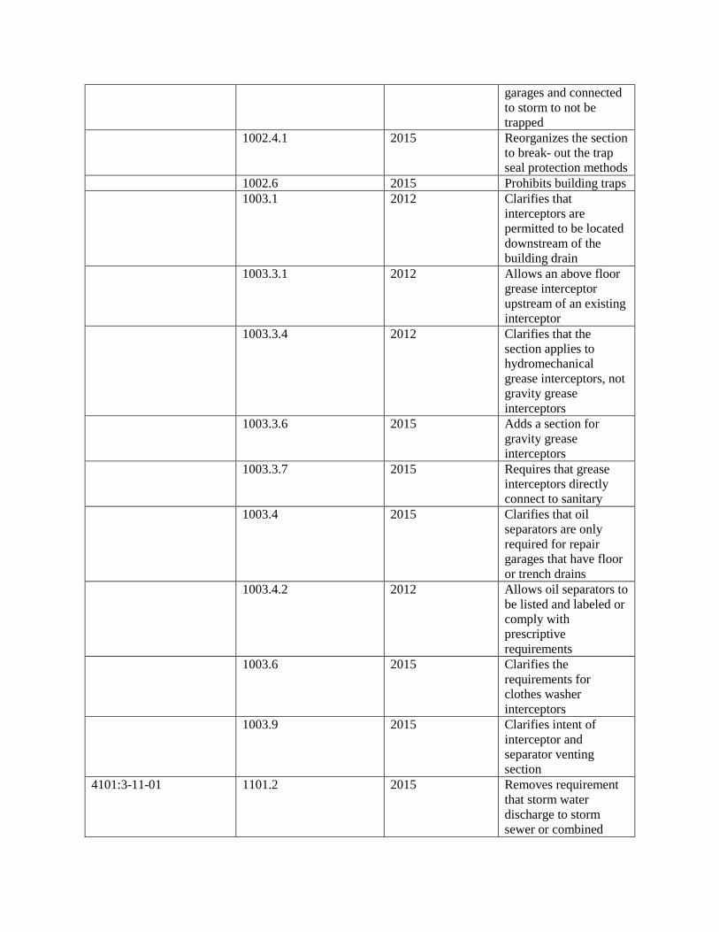
garages and connected to storm to not be trapped
1002.4.1 2015 Reorganizes the section to break- out the trap seal protection methods
1002.6 2015 Prohibits building traps 1003.1 2012 Clarifies that
interceptors are permitted to be located downstream of the building drain
1003.3.1 2012 Allows an above floor grease interceptor upstream of an existing interceptor
1003.3.4 2012 Clarifies that the section applies to hydromechanical grease interceptors, not gravity grease interceptors
1003.3.6 2015 Adds a section for gravity grease interceptors
1003.3.7 2015 Requires that grease interceptors directly connect to sanitary
1003.4 2015 Clarifies that oil separators are only required for repair garages that have floor or trench drains
1003.4.2 2012 Allows oil separators to be listed and labeled or comply with prescriptive requirements
1003.6 2015 Clarifies the requirements for clothes washer interceptors
1003.9 2015 Clarifies intent of interceptor and separator venting section
4101:3-11-01 1101.2 2015 Removes requirement that storm water discharge to storm sewer or combined
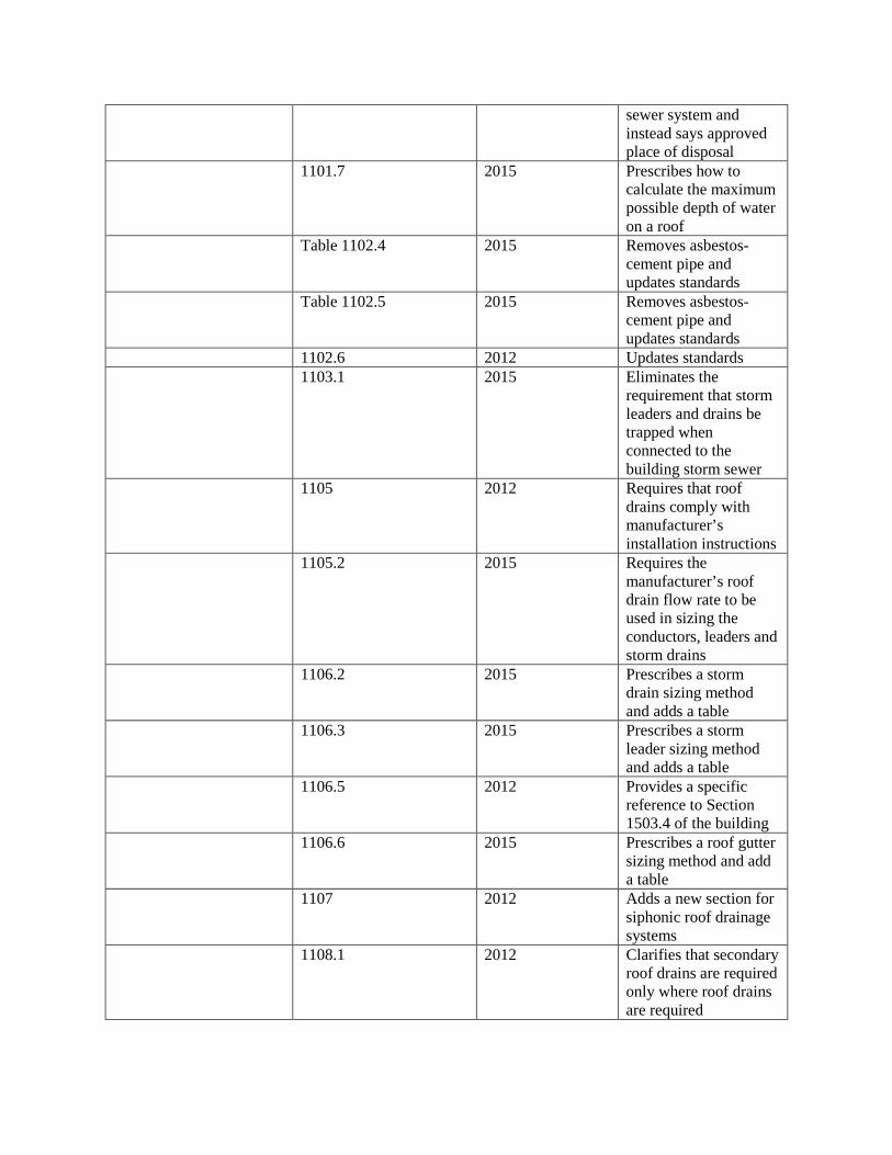
sewer system and instead says approved place of disposal
1101.7 2015 Prescribes how to calculate the maximum possible depth of water on a roof
Table 1102.4 2015 Removes asbestos-cement pipe and updates standards
Table 1102.5 2015 Removes asbestos-cement pipe and updates standards
1102.6 2012 Updates standards 1103.1 2015 Eliminates the
requirement that storm leaders and drains be trapped when connected to the building storm sewer
1105 2012 Requires that roof drains comply with manufacturer’s installation instructions
1105.2 2015 Requires the manufacturer’s roof drain flow rate to be used in sizing the conductors, leaders and storm drains
1106.2 2015 Prescribes a storm drain sizing method and adds a table
1106.3 2015 Prescribes a storm leader sizing method and adds a table
1106.5 2012 Provides a specific reference to Section 1503.4 of the building
1106.6 2015 Prescribes a roof gutter sizing method and add a table
1107 2012 Adds a new section for siphonic roof drainage systems
1108.1 2012 Clarifies that secondary roof drains are required only where roof drains are required
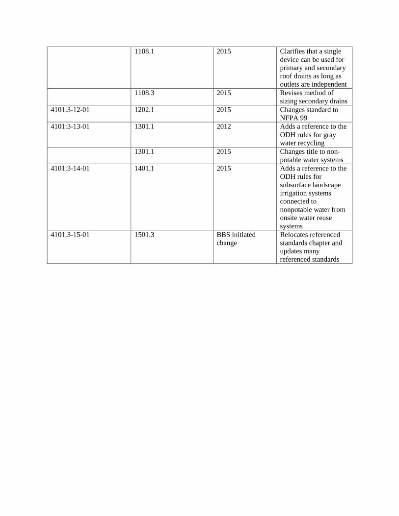
1108.1 2015 Clarifies that a single device can be used for primary and secondary roof drains as long as outlets are independent
1108.3 2015 Revises method of sizing secondary drains
4101:3-12-01 1202.1 2015 Changes standard to NFPA 99
4101:3-13-01 1301.1 2012 Adds a reference to the ODH rules for gray water recycling
1301.1 2015 Changes title to non-potable water systems
4101:3-14-01 1401.1 2015 Adds a reference to the ODH rules for subsurface landscape irrigation systems connected to nonpotable water from onsite water reuse systems
4101:3-15-01 1501.3 BBS initiated change
Relocates referenced standards chapter and updates many referenced standards


