Effect on Solidification Structure of Hypoeutectic Grey ...
5
Effect on Solidification Structure of Hypoeutectic Grey Cast Iron by Vacuum Condition in Lost Foam Casting XIE Mingguo 1, a , ZHU Changan 1, b* and ZHOU Jianxin 2, c 1 School of engineering science, University of science and technology of China, Hefei 230026, China 2 State Key Laboratory of Materials Processing and Die & Mould Technology, Huazhong University of Science and Technology, Wuhan 430074, China a. [email protected], b.* Corresponding author: [email protected], c. [email protected] Keywords: Hypoeutectic grey cast iron, Solidification structure, lost foam casting Abstract. In this paper, the solidification structure of hypoeutectic grey iron under different vacuum conditions in lost foam casting (LFC) were discussed. In order to better research solidification structure under different cooling conditions, we designed different thickness step test casting and took actual casting experiment in two vacuum degree environments (0.02MP and 0.055MP). By setting the thermocouple to the cooling curves during the mold filling and solidification process is recorded at the center of different thickness step. Finally, through the use of thermal analysis and metallurgical comparative analysis, the solidification structure feature of hypoeutectic gray cast iron in lost foam casting process by vacuum degree environments is demonstrated to guide designer to advance the casting processes design. Introduction LFC is a technology near and precise shaped casting process which known as highly promising [1] . Different from the general cavity of sand casting, LFC is characterized in the role of negative pressure, foam models form in sealed tight sandbox dry sand. During liquid metal filling, the foam gradually form pyrolysis, gasification and liquefaction or discharged under the action of heat liquid metal and through the vacuum system. After the liquid metal replace original foam mold, the cavity is formed to be the casting. Classic lost foam casting process is shown in Fig. 1. Figure 1 Classic lost foam casting processes Because of above specific phenomenon in lost foam casting, the initial temperature field is greatly affected by the mold filling process in vacuum degree environments to effect on the solidification process and further change feature of final solidification structure of casting. In recent years, considering characteristics of the lost foam casting, lots of researchers [2-7] pay more attention to understand characteristics of mold-filling and pyrolysis of cast iron. Through experiments and mathematical methods, they built the fluid melt and temperature distribution models of interface moving of metal and foam. Meanwhile, researchers [8-11] have also focused on the possible casting defects in LFC, such as gas cavity, carbon black, wrinkled skin, shrinkage and etc. In the studies of the microstructure and properties, the researchers [12-13] established the relationship of foam material, production process and preparation of the alloy with graphite morphology. However, few reports are emerged to study the unique structural features of hypoeutectic grey iron by measuring the cooling curves of casting and its detailed analysis. International Conference on Manufacturing Science and Engineering (ICMSE 2015) © 2015. The authors - Published by Atlantis Press 1496
Transcript of Effect on Solidification Structure of Hypoeutectic Grey ...

Effect on Solidification Structure of Hypoeutectic Grey Cast Iron by Vacuum Condition in Lost Foam Casting
XIE Mingguo1, a , ZHU Changan1, b* and ZHOU Jianxin2, c 1 School of engineering science, University of science and technology of China,
Hefei 230026, China 2 State Key Laboratory of Materials Processing and Die & Mould Technology,
Huazhong University of Science and Technology, Wuhan 430074, China a. [email protected], b.*Corresponding author: [email protected],
Keywords: Hypoeutectic grey cast iron, Solidification structure, lost foam casting Abstract. In this paper, the solidification structure of hypoeutectic grey iron under different vacuum conditions in lost foam casting (LFC) were discussed. In order to better research solidification structure under different cooling conditions, we designed different thickness step test casting and took actual casting experiment in two vacuum degree environments (0.02MP and 0.055MP). By setting the thermocouple to the cooling curves during the mold filling and solidification process is recorded at the center of different thickness step. Finally, through the use of thermal analysis and metallurgical comparative analysis, the solidification structure feature of hypoeutectic gray cast iron in lost foam casting process by vacuum degree environments is demonstrated to guide designer to advance the casting processes design.
Introduction LFC is a technology near and precise shaped casting process which known as highly promising [1]. Different from the general cavity of sand casting, LFC is characterized in the role of negative pressure, foam models form in sealed tight sandbox dry sand. During liquid metal filling, the foam gradually form pyrolysis, gasification and liquefaction or discharged under the action of heat liquid metal and through the vacuum system. After the liquid metal replace original foam mold, the cavity is formed to be the casting. Classic lost foam casting process is shown in Fig. 1.
Figure 1 Classic lost foam casting processes
Because of above specific phenomenon in lost foam casting, the initial temperature field is greatly affected by the mold filling process in vacuum degree environments to effect on the solidification process and further change feature of final solidification structure of casting.
In recent years, considering characteristics of the lost foam casting, lots of researchers [2-7] pay more attention to understand characteristics of mold-filling and pyrolysis of cast iron. Through experiments and mathematical methods, they built the fluid melt and temperature distribution models of interface moving of metal and foam. Meanwhile, researchers[8-11] have also focused on the possible casting defects in LFC, such as gas cavity, carbon black, wrinkled skin, shrinkage and etc. In the studies of the microstructure and properties, the researchers [12-13] established the relationship of foam material, production process and preparation of the alloy with graphite morphology. However, few reports are emerged to study the unique structural features of hypoeutectic grey iron by measuring the cooling curves of casting and its detailed analysis.
International Conference on Manufacturing Science and Engineering (ICMSE 2015)
© 2015. The authors - Published by Atlantis Press 1496

However, in the vacuum environment, the influence of different vacuum degree on hypoeutectic gray cast iron studies rarely reported. In this paper, characteristics of solidification conditions and corresponding structure are revealed by thermal analysis from the mold-filling stage and the solidification stage of melt.
Experimental In this paper, stepped test bar and thermocouple arrangement is shown in Fig. 2. The K-type thermocouple is used with 1mm diameter. Thermocouple is installed into corresponding measured position of casting model embed under dry sandbox. 6 temperature measurement points is set in this experiment: the wall thickness for 6 measuring points is 5, 10, 15, 20, 30 and 45 respectively.
. Figure 2 Step test casting and thermal-couple installation
Figure 3 Practical pouring experiments
Figure 4 Vacuum condition setting in pouring (Left: Higher degree; Right: Lower Degree)
Each group of thermocouples is connected to measurement device and PC (Agilent 34972A). The PC is starting to record the cooling data when the melt is pouring in actual implementation of the foundry , as shown in Fig. 3 and Fig. 4. The pouring condition and parameter is shown in the Table 1.
Table 1 Pouring parameter and composition of hypoeutectic grey cast iron Pouring Temperature(time)
Vacuum Chemical composition(%) 0.02 Mp C Si Mn P S CE%
1400(10s) 0.055Mp 3.12 1.73 0.83 0.023 0.045 3.64
Carbon equivalent: CE= C+ 0.3(Si+P) – 0.03Mn + 0.4S; Temperature cooling data (as shown in Fig. 5) at measuring points is integrity and could describe
characteristic of temperature change for the hypoeutectic grey cast iron, and also showed features of a cooling rate variation with the thickness of the position change.
1497

Figure 5 cooling curve recording of measurement points in vacuum condition (Left: higher degree;
Right: lower degree)
Result and Discussion Thermal analysis is useful tools to analyze the key temperature point on the cooling curve. Typical relationship between cooling curve and first derivative curve is presented in Fig. 6.
Figure 6 Typical cooling curve and first
derivative curve
Figure 7 Average cooling rates during
mold-filling Figure 8 Temperature of primary
austenite formation Average cooling rate during mold-filling: As shown in Fig. 7, cooling rate is the highest at the
thinnest point and deceases with the increasing wall thickness. In higher vacuum condition the cooling rate is overall slightly higher than in lower vacuum conditions.
Primary austenite formation: As shown in Fig. 8, in thinner part, the difference of temperature of primary austenite formation is obvious large, however, the difference is small in thickness part.
Figure 9 the compassion of the
undercooling degree Figure 10 Interval period of eutectic
solidification
TE’ Stable (graphite) eutectic equilibrium temperature TE Metastable (carbide) eutectic equilibrium temperature Tmax Maximum Temperature of cooling curve TAL Liquid temperature of austenitic precipitation TES Temperature of start of eutectic freezing TEU Lowest eutectic temperature TER Highest eutectic temperature TEN Temperature of the end of solidification △TE Eutectic undercooling of grey cast iron,(TE- TEU)
1498

Eutectic formation: In this paper, Eutectic solidification undercooling degree: △TE=1150˚C-TE. As shown in Fig. 9, because of higher cooling rate in thinner part, the undercooling at No. 1 measurement point is large and decrease with the increasing wall thickness in higher and lower vacuum condition
End of Solidification: It is generally believed that the lower TES and the easier to form carbide and shrinkage defects. The analysis of TES value shows that different vacuum condition observe a similar rule which with the increase of wall thickness, and TES value has a trend of increase, as shown in Fig. 10.
Using wire cutting approach to cut the step test cast in each thermocouple position, the 20X20mm sample is obtained to observe microstructure differences of sample section face with cooling curve information and analysis.
No. 6 No. 5 No. 4 No. 3 No. 2 No. 1
Figure 11 graphite types of samples (Up: lower degree; Down: higher degree)
No. 6 No. 5 No. 4 No. 3 No. 2 No. 1 Figure 12 matrix structures of samples (Up: lower degree; Down: higher degree)
Fig. 11 and Fig. 12 show metallograph including graphite types and matrix structure at temperature measurement points. During mold filling process of grey iron melt in vacuum environment, the temperature drops quickly, he graphite type is mainly formed D-type at the No. 1 sample (The thinnest position). The shape of graphite is similar between in higher and lower vacuum condition. On the other hand, the matrix structures consist of pearlite and ferrite. However, the ratio of pearlite is larger in higher vacuum condition than lower one. In 2 to 6 measurement point, with the increasing of the thickness, graphite morphology is transformed to A-type graphite and matrix structures is mainly pearlite. By analyzing TAL, TE and TEN, difference of key parameters is small between higher vacuum conditions than lower one. Therefore, the vacuum environment is limited to impact on further solidification process after finishing filling processes. So, graphite morphology in both vacuum environments is close and no significant difference of matrix structures.
Summary In this paper, we focuses on understand solidification characteristics hypoeutectic gray cast iron under different vacuum environment in lost foam casting. By obtaining the cooling curves and using thermal
1499
analysis to analyze microstructure of final solidification structure, the conclusions are deduced as follow:
(1) Temperature cooling curve: Heat loss of melt is significantly influenced by the filling process under vacuum environment, and ultimately effects on the cooling conditions of the solidification process. Particular in the thinner part, the cooling rate is the most obvious impacted, however, at thicker wall no significant difference is found.
(2) Solidification microstructure: With the increasing thickness of the casting, graphite structure is transformed from D-type graphite to be the A-type graphite and matrix structure of pearlite also is increased. Like the phenomenon found in cooling curve, the impact degree is more critical by higher vacuum condition in thinner part.
From above analysis, the vacuum condition significantly affects the filling process and lightly impact on the solidification processes. This effect is more sensitive in the thin wall area.
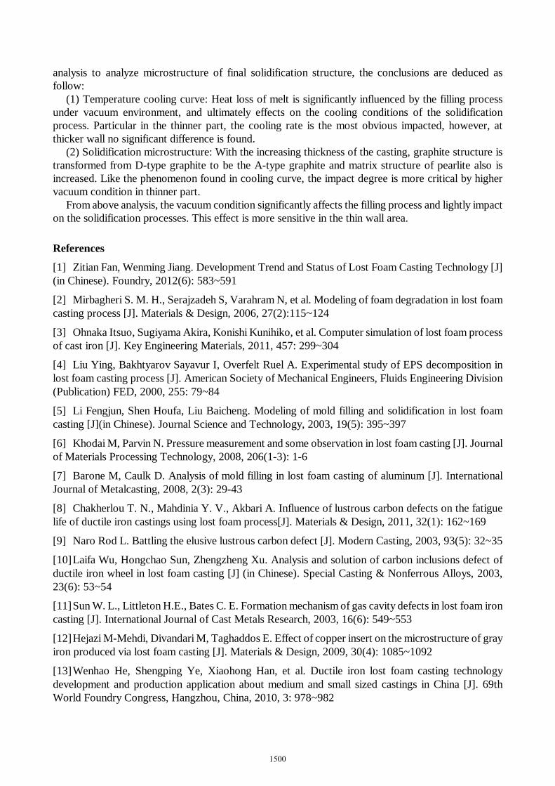
References
[1] Zitian Fan, Wenming Jiang. Development Trend and Status of Lost Foam Casting Technology [J] (in Chinese). Foundry, 2012(6): 583~591
[2] Mirbagheri S. M. H., Serajzadeh S, Varahram N, et al. Modeling of foam degradation in lost foam casting process [J]. Materials & Design, 2006, 27(2):115~124
[3] Ohnaka Itsuo, Sugiyama Akira, Konishi Kunihiko, et al. Computer simulation of lost foam process of cast iron [J]. Key Engineering Materials, 2011, 457: 299~304
[4] Liu Ying, Bakhtyarov Sayavur I, Overfelt Ruel A. Experimental study of EPS decomposition in lost foam casting process [J]. American Society of Mechanical Engineers, Fluids Engineering Division (Publication) FED, 2000, 255: 79~84
[5] Li Fengjun, Shen Houfa, Liu Baicheng. Modeling of mold filling and solidification in lost foam casting [J](in Chinese). Journal Science and Technology, 2003, 19(5): 395~397
[6] Khodai M, Parvin N. Pressure measurement and some observation in lost foam casting [J]. Journal of Materials Processing Technology, 2008, 206(1-3): 1-6
[7] Barone M, Caulk D. Analysis of mold filling in lost foam casting of aluminum [J]. International Journal of Metalcasting, 2008, 2(3): 29-43
[8] Chakherlou T. N., Mahdinia Y. V., Akbari A. Influence of lustrous carbon defects on the fatigue life of ductile iron castings using lost foam process[J]. Materials & Design, 2011, 32(1): 162~169
[9] Naro Rod L. Battling the elusive lustrous carbon defect [J]. Modern Casting, 2003, 93(5): 32~35
[10] Laifa Wu, Hongchao Sun, Zhengzheng Xu. Analysis and solution of carbon inclusions defect of ductile iron wheel in lost foam casting [J] (in Chinese). Special Casting & Nonferrous Alloys, 2003, 23(6): 53~54
[11] Sun W. L., Littleton H.E., Bates C. E. Formation mechanism of gas cavity defects in lost foam iron casting [J]. International Journal of Cast Metals Research, 2003, 16(6): 549~553
[12] Hejazi M-Mehdi, Divandari M, Taghaddos E. Effect of copper insert on the microstructure of gray iron produced via lost foam casting [J]. Materials & Design, 2009, 30(4): 1085~1092
[13] Wenhao He, Shengping Ye, Xiaohong Han, et al. Ductile iron lost foam casting technology development and production application about medium and small sized castings in China [J]. 69th World Foundry Congress, Hangzhou, China, 2010, 3: 978~982
1500