Effect of zeolite A coating thickness on adsorption kinetics for heat pump applications
7
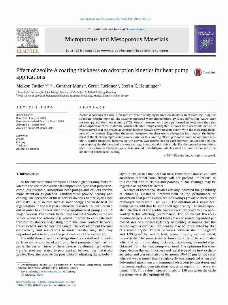
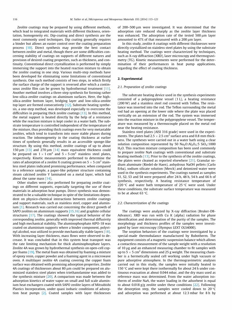
Effect of zeolite A coating thickness on adsorption kinetics for heat pump applications Melkon Tatlier a,b,⇑,1 , Gunther Munz a , Gerrit Fueldner a , Stefan K. Henninger a a Fraunhofer Institute for Solar Energy Systems, Heidenhofstr. 2, 79110 Freiburg, Germany b Department of Chemical Engineering, Istanbul Technical University, Maslak, 34469 Istanbul, Turkey article info Article history: Received 11 August 2013 Received in revised form 11 March 2014 Accepted 11 March 2014 Available online 19 March 2014 Keywords: Zeolite Coating Thickness Adsorption kinetics abstract Zeolite A coatings of various thicknesses were directly crystallized on stainless steel plates by using the substrate heating method. The coatings prepared were characterized by X-ray diffraction (XRD), laser microscopy and thermogravimetry (TG). Kinetic measurements were performed to determine the rates of adsorption of these materials, which exhibited rough corrugated surfaces with accessible nature. It was observed that the overall adsorption kinetics slowed down to some extent with the increasing thick- ness of the coatings. Regarding the power estimated for their use in adsorption heat pumps, the higher mass of the thicker samples could compensate for this limiting effect up to some point. An optimum zeo- lite A coating thickness, maximizing the power, was determined to exist between 58 lm and 176 lm, representing the thinnest and thickest coatings investigated in this study. For the operating conditions used, the optimum thickness value was around 130–140 lm, which varied to some extent with the amount of normalized loading. Ó 2014 Elsevier Inc. All rights reserved. 1. Introduction As the environmental problems and the high operating costs re- lated to the use of conventional compression-type heat pumps be- come less tolerable, adsorption heat pumps and chillers receive more attention as potential candidates to provide heating and cooling. The operation of these devices involves natural cycles that can make use of sources such as solar energy and waste heat for regeneration. In the last years, intensive research has been carried out in order to commercialize the adsorption heat pump [1–4].A major concern is to provide better heat and mass transfer in the ad- sorber where the adsorbent is placed in order to eliminate heat transfer resistances originating from the poor contact between the adsorbent and the heat exchanger. The low adsorbent thermal conductivity and resistances to mass transfer may also play important roles in limiting the performance of the system [5]. The utilization of zeolite coatings directly crystallized on metal surfaces in the adsorber of adsorption heat pumps/chillers may im- prove the performances of these devices by eliminating the heat transfer problem related to poor contact between the metal and zeolite. They also provide the possibility of adjusting the adsorbent layer thickness in a manner that mass transfer resistances and low adsorbent thermal conductivity will not present limitations. In this context, the thickness and porosity of the coatings may be regarded as significant factors. A series of theoretical studies actually indicated the possibility of obtaining substantial improvement in the performance of adsorption heat pumps when zeolite coatings grown on metal heat exchanger tubes were used [6–9]. The duration of a single heat pump cycle could thus be shortened significantly. The mass equiv- alent thickness of the zeolite coatings was observed to be a note- worthy factor affecting performance. The equivalent thickness mentioned here is calculated from (mass of zeolite deposited per coated area of substrate)/(density of zeolite). Assuming that the zeolite layer is compact, the density may be represented by that of a zeolite crystal. This value varies between about 1.52 g/cm 3 and 1.99 g/cm 3 for zeolite NaA, when it is dry and saturated, respectively. The mass transfer limitations could be eliminated when the optimum coating thickness, maximizing the useful effect obtained from the heat pump was used. The optimum thickness depended on the wall thickness and metal type of the heat exchan- ger tubes and was estimated to be around 50–100 lm for the cases where it was assumed that a single cycle was completed when pre- determined maximum and minimum adsorbent temperatures and the corresponding concentration values at equilibrium were at- tained [7,8]. This value increased to about 150 lm when the cycle durations were also optimized [9]. http://dx.doi.org/10.1016/j.micromeso.2014.03.017 1387-1811/Ó 2014 Elsevier Inc. All rights reserved. ⇑ Corresponding author at: Department of Chemical Engineering, Istanbul Technical University, Maslak, 34469 Istanbul, Turkey. E-mail address: [email protected] (M. Tatlier). 1 On sabbatical leave. Microporous and Mesoporous Materials 193 (2014) 115–121 Contents lists available at ScienceDirect Microporous and Mesoporous Materials journal homepage: www.elsevier.com/locate/micromeso
Transcript of Effect of zeolite A coating thickness on adsorption kinetics for heat pump applications
Microporous and Mesoporous Materials 193 (2014) 115–121
Contents lists available at ScienceDirect
Microporous and Mesoporous Materials
journal homepage: www.elsevier .com/locate /micromeso
Effect of zeolite A coating thickness on adsorption kinetics for heat pumpapplications
http://dx.doi.org/10.1016/j.micromeso.2014.03.0171387-1811/� 2014 Elsevier Inc. All rights reserved.
⇑ Corresponding author at: Department of Chemical Engineering, IstanbulTechnical University, Maslak, 34469 Istanbul, Turkey.
E-mail address: [email protected] (M. Tatlier).1 On sabbatical leave.
Melkon Tatlier a,b,⇑,1, Gunther Munz a, Gerrit Fueldner a, Stefan K. Henninger a
a Fraunhofer Institute for Solar Energy Systems, Heidenhofstr. 2, 79110 Freiburg, Germanyb Department of Chemical Engineering, Istanbul Technical University, Maslak, 34469 Istanbul, Turkey
a r t i c l e i n f o a b s t r a c t
Article history:Received 11 August 2013Received in revised form 11 March 2014Accepted 11 March 2014Available online 19 March 2014
Keywords:ZeoliteCoatingThicknessAdsorption kinetics
Zeolite A coatings of various thicknesses were directly crystallized on stainless steel plates by using thesubstrate heating method. The coatings prepared were characterized by X-ray diffraction (XRD), lasermicroscopy and thermogravimetry (TG). Kinetic measurements were performed to determine the ratesof adsorption of these materials, which exhibited rough corrugated surfaces with accessible nature. Itwas observed that the overall adsorption kinetics slowed down to some extent with the increasing thick-ness of the coatings. Regarding the power estimated for their use in adsorption heat pumps, the highermass of the thicker samples could compensate for this limiting effect up to some point. An optimum zeo-lite A coating thickness, maximizing the power, was determined to exist between 58 lm and 176 lm,representing the thinnest and thickest coatings investigated in this study. For the operating conditionsused, the optimum thickness value was around 130–140 lm, which varied to some extent with theamount of normalized loading.
� 2014 Elsevier Inc. All rights reserved.
1. Introduction
As the environmental problems and the high operating costs re-lated to the use of conventional compression-type heat pumps be-come less tolerable, adsorption heat pumps and chillers receivemore attention as potential candidates to provide heating andcooling. The operation of these devices involves natural cycles thatcan make use of sources such as solar energy and waste heat forregeneration. In the last years, intensive research has been carriedout in order to commercialize the adsorption heat pump [1–4]. Amajor concern is to provide better heat and mass transfer in the ad-sorber where the adsorbent is placed in order to eliminate heattransfer resistances originating from the poor contact betweenthe adsorbent and the heat exchanger. The low adsorbent thermalconductivity and resistances to mass transfer may also playimportant roles in limiting the performance of the system [5].
The utilization of zeolite coatings directly crystallized on metalsurfaces in the adsorber of adsorption heat pumps/chillers may im-prove the performances of these devices by eliminating the heattransfer problem related to poor contact between the metal andzeolite. They also provide the possibility of adjusting the adsorbent
layer thickness in a manner that mass transfer resistances and lowadsorbent thermal conductivity will not present limitations. Inthis context, the thickness and porosity of the coatings may beregarded as significant factors.
A series of theoretical studies actually indicated the possibilityof obtaining substantial improvement in the performance ofadsorption heat pumps when zeolite coatings grown on metal heatexchanger tubes were used [6–9]. The duration of a single heatpump cycle could thus be shortened significantly. The mass equiv-alent thickness of the zeolite coatings was observed to be a note-worthy factor affecting performance. The equivalent thicknessmentioned here is calculated from (mass of zeolite deposited percoated area of substrate)/(density of zeolite). Assuming that thezeolite layer is compact, the density may be represented by thatof a zeolite crystal. This value varies between about 1.52 g/cm3
and 1.99 g/cm3 for zeolite NaA, when it is dry and saturated,respectively. The mass transfer limitations could be eliminatedwhen the optimum coating thickness, maximizing the useful effectobtained from the heat pump was used. The optimum thicknessdepended on the wall thickness and metal type of the heat exchan-ger tubes and was estimated to be around 50–100 lm for the caseswhere it was assumed that a single cycle was completed when pre-determined maximum and minimum adsorbent temperatures andthe corresponding concentration values at equilibrium were at-tained [7,8]. This value increased to about 150 lm when the cycledurations were also optimized [9].
116 M. Tatlier et al. / Microporous and Mesoporous Materials 193 (2014) 115–121
Zeolite coatings may be prepared by using different methods,which lead to integrated materials with different thickness, orien-tation, homogeneity etc. Dip-coating and direct synthesis are themost commonly used techniques. Dip coating generally requiresa binder but allows an easier control over the coating preparationprocess [10]. Direct synthesis may provide the best contactbetween zeolite and metal, though there are some difficulties con-cerning stability of coatings on supports of different natures andprovision of desired coating properties, such as thickness, and con-tinuity. Conventional direct crystallization is performed by simplyimmersing the support into the heated reaction mixture to obtainthe zeolite coating in one step. Various multi-step methods havebeen developed for eliminating some limitations of conventionalsynthesis. One such method consists of two steps, in which firstlythe surface charge of the support is reversed after which a contin-uous zeolite film can be grown by hydrothermal treatment [11].Another method involves a three-step synthesis for forming ratherlow-silica-zeolite coatings on aluminum surfaces. Here, the high-silica-zeolite bottom layer, bridging layer and low-silica-zeolitetop layer are formed consecutively [12]. Substrate heating synthe-sis, a one-step method, was developed especially to overcome thedifficulties in preparing thick zeolite coatings [13]. In this method,the metal support is heated directly by the help of a resistancewhile the reaction mixture is kept cooler in a water bath. The sub-strate temperature is controlled independent of the temperature ofthe mixture, thus providing thick coatings even for very metastablezeolites, which tend to transform into more stable phases duringreaction. The inhomogeneity in the coating thickness at earliertimes of synthesis generally results in an accessible sponge-likestructure. By using this method, zeolite coatings of up to about150 lm [13] and 270 lm [14] mass equivalent thickness couldbe prepared on 1 � 1 cm2 and 5 � 5 cm2 stainless steel plates,respectively. Kinetic measurements performed to determine therates of adsorption of a zeolite X coating grown on 5 � 5 cm2 stain-less steel plates indicated promising performance, when comparedto a reference sample, a paper-like polymer structure containingsteam calcined zeolite Y laminated on a metal layer, which hadabout the same mass [14].
Other studies were also performed for preparing zeolite coat-ings on different supports, especially targeting the use of thesematerials in adsorption heat pumps. Direct synthesis was demon-strated to be a valuable technique in spite of the limitations depen-dent on physico-chemical interactions between zeolite coatingsand support materials, such as stainless steel, copper and alumin-ium [1]. Research was carried out concerning the direct growth ofSAPO zeolites on aluminium supports [15,16] and graphite cellularstructures [17]. The coatings showed the typical behavior of thecorresponding zeolite, generally with improved thermal diffusivityand high mechanical stability. The aluminophosphate AIPO-18 wascoated on aluminium supports where a binder component, polyvi-nyl alcohol, was utilized to provide mechanically stable layers [18].With increasing layer thickness, mass flows were observed to de-crease. It was concluded that in this system heat transport wasthe rate limiting mechanism for thick aluminophosphate layers.Zeolite 4A was grown by hydrothermal synthesis on open-cell cop-per foams [19]. The metal foam was obtained by foaming a mixtureof epoxy resin, copper powder and a foaming agent in a microwaveoven. A multilayer zeolite 4A coating covering the copper foamsurface was obtained with promising adsorption properties. Zeolite4A coatings of thicknesses about 80 lm could be prepared on alu-minized stainless steel plates when triethanolamine was added tothe synthesis mixture [20]. A comparison was made between theadsorption kinetics of water vapor on small and full scale alumin-ium heat exchangers coated with SAPO zeolite layers of MitsubishiPlastics Incorporation, under quasi isobaric conditions of adsorp-tion heat pumps [2]. Coated samples with layer thicknesses
of 200–500 lm were investigated. It was determined that theadsorption rate reduced sharply as the zeolite layer thicknesswas enhanced. The adsorption rate of the tested 500 lm layeramounted to 47% of that measured with a 200 lm layer.
In this study, zeolite A coatings with different thicknesses weredirectly crystallized on stainless steel plates by using the substrateheating method. The coatings were characterized by techniques,such as X-ray diffraction (XRD), laser microscopy and thermogravi-metry (TG). Kinetic measurements were performed for the deter-mination of their performances in heat pump applications,regarding the effect of coating thickness.
2. Experimental
2.1. Preparation of zeolite coatings
The substrate heating device used in the synthesis experimentsconsisted of a polypropylene vessel (1 L), a heating resistance(200 W) and a stainless steel rod covered with Teflon. The resis-tance was inserted into the rod. The Teflon surrounding the metalrod had an opening at the lower side where the plate was placedvertically on an extension of the rod. The system was immersedinto the reaction mixture in the polypropylene vessel. The temper-ature was measured by a thermocouple placed on the metal rodnear the heating resistance.
Stainless steel plates (AISI 316 grade) were used in the experi-ments. The plates had 2.5 � 2.5 cm2 surface area and 0.8 mm thick-ness. The syntheses were carried out in a water bath using a clearsolution composition represented by 50 Na2O:Al2O3:5 SiO2:1000H2O. This reaction mixture composition has been used commonlyto prepare zeolite NaA coatings with conventional and substrateheating methods [13]. Prior to the synthesis of the zeolite coatings,the plates were cleaned as reported elsewhere [21]. Granular so-dium aluminate (Riedel-de Haen), anhydrous NaOH pellets (CarloErba), sodium silicate solution (Merck) and deionized water wereused in the synthesis experiments. The coatings named as samplesS1, S2, S3 and S4 were prepared after 24 h, 48 h, 54 h and 66 h ofsynthesis, respectively. A heating resistance temperature of220 �C and water bath temperature of 25 �C were used. Underthese conditions, the substrate surface temperature was measuredto be at about 63 �C.
2.2. Characterization of the coatings
The coatings were analyzed by X-ray diffraction (Bruker-D8-Advance). XRD was run with Cu K (alpha) radiation for phaseidentification and determination of the purity of the samples. Themorphology and thickness profiles of the samples were investi-gated by laser microscopy (Olympus LEXT OLS4000).
The sorption behaviors of the coatings were investigated by aspecial-made thermobalance manufactured by Rubotherm. Theequipment consists of a magnetic suspension balance which allowsa contactless measurement of the sample weight with a resolutionof 10 lg and an enhanced measuring chamber to fit samples withup to 5 � 5 cm2 dimensions and 25 g weight. The measuring cham-ber is a hermetically sealed cell working under high vacuum orpure adsorptive atmosphere. In the thermogravimetric analysescarried out in this study, the samples were initially heated to150 �C and were kept there isothermally for about 24 h under con-tinuous evacuation at about 0.044 mbar, and the dry mass used asreference mass was determined. From the water adsorption iso-therm of zeolite NaA, the water loading in the adsorbent is equalto about 0.018 g/g zeolite under these conditions [22]. Followingthe desorption step, the samples were cooled down to 20 �Cand adsorption was performed at about 12.3 mbar for 8 h by

M. Tatlier et al. / Microporous and Mesoporous Materials 193 (2014) 115–121 117
continuous evaporation of water from a reservoir into the mea-surement cell. A few other desorption–adsorption steps followedwhere the temperature and pressure were varied between 20–150 �C and 12.3–55.0 mbar, respectively. Equilibrium measure-ments were made during these different steps.
2.3. Measurement of adsorption kinetics
The adsorption kinetics depend on the type of materials (adsor-bent, fluid) used, the environmental conditions (starting pressure,temperature, initial loading) as well as the heat and mass transferproperties, mainly determined by the effective heat conductivityand diffusivity inside the adsorbent material and by the contact be-tween the adsorbent and the heat exchanger surface.
Different setups and methodologies are proposed in the litera-ture for the dynamic evaluation of adsorbents. Mainly, two differ-ent approaches are used. The first one is the large pressure jump(LPJ) method [18,23], where adsorption is initiated by a pressurejump imposed to the sample, continuously cooled by an externalsource. In this method, the heat transfer properties of the samplesstill have major influence in the experiments due to the heat re-leased during adsorption. The second one is the large temperaturejump (LTJ) method [24–26], which may simulate the almost iso-baric adsorption stage in the heat transformation cycle. Addition-ally, the development of detailed physico-mathematical models[27] for the description of the non-isothermal transient adsorptionprocess provides a powerful tool for the evaluation of physicalparameters [28], which can be employed to make predictive simu-lations of the performance of an adsorption heat pump whose ad-sorber configuration has been tested on small scale, e.g. by LPJexperiments.
The kinetics measurements were performed with the largepressure jump method in this study. The different coatings pre-pared on stainless steel plates were characterized in the adsorptionkinetics test facility in the labs of Fraunhofer ISE. The kinetic mea-surements were performed using the device shown in Fig. 1.
The kinetic device was composed of two major units: a dosingchamber and a small measurement cell. The sample was placedin the measurement cell on a thermostat-controlled cold platewhich was passed-through by water at constant temperature(40 �C). The dosing chamber was loaded with water vapor and
Fig. 1. Scheme of the kineti
the amount of water was given by an equation of state calculatedfrom volume, temperature and pressure of the gas. Different watervapor pressures could be obtained by a thermostated water reser-voir. The pressure was measured inside both chambers by capaci-tive sensors (MKS Baratron 628), with a range of 1–10’000 Pa witha resolution of 1 Pa. Surface temperature was measured contactlesswith an infrared sensor placed above the sample. By this detectionmethod, the sharp initial rise in temperature at the beginning ofthe adsorption could be followed with an error value of ±1 K.
There were three main stages in each measurement, namely,desorption, cooling and adsorption. Desorption was performed at95 �C by vacuum (�1 Pa) applied to the measuring chamber,resulting in the evacuation of most of the water content of theadsorbent (valve 4 in Fig. 1 was opened). From the water isothermof zeolite NaA, at 95 �C and 1 Pa, the water loading in the adsorbentmay be seen to be equal to about 0.02 g/g zeolite [22]. The mea-surements were performed with a water vapor pressure appliedto the dosing chamber, which was set to 15 mbar. During the cool-ing step, the adsorbent, which was warmed up to 95 �C during thedesorption stage, was cooled down to 40 �C. For the final stage,valve 1 was opened allowing the water vapor to be adsorbed bythe adsorbent in the measurement chamber. As the system waskept at constant volume and the total dosed water vapor changedonly by adsorption, the water uptake of the sample could be deter-mined by the pressure decrease. Before opening valve 1, theamount of water was calculated by pressure, temperature and vol-ume of the dosing chamber. This gave the maximum amount ofwater involved in the kinetic measurements. After opening valve1, the adsorbed amount of water was calculated from the differ-ence between this maximum amount and the amount of water inthe gas phase. The latter was calculated by taking into consider-ation the combined volumes of dosing and sample chambers.
3. Results and discussion
The dry masses of the coatings prepared were equal to about55.6 mg, 123.8 mg, 133.8 mg and 167.2 mg for samples S1, S2, S3and S4, respectively. These mass values were determined fromTG measurements. The X-ray diffraction analyses indicated thatthe coatings prepared on stainless steel plates consisted of purezeolite A crystals. The XRD pattern of sample S2 is given in Fig. 2
c measurement device.

Fig. 3. 2-D laser microscope image of sample S4.
118 M. Tatlier et al. / Microporous and Mesoporous Materials 193 (2014) 115–121
as an example, together with the main peaks of a reference zeoliteA sample.
2-D and 3-D laser microscope images of sample S4 are shown inFigs. 3 and 4, respectively. It may be observed from Fig. 3 that zeo-lite covered the surface of the plate. The corrugated open nature ofzeolite coatings prepared by using the substrate heating methodmay be observed from Fig. 4. The cross-sectional profiles of thecoatings S1, S2, S3 and S4 are given in Fig. 5(a–d), respectively.The high surface roughness of the coatings may be seen clearlyfrom these profiles obtained by laser microscopy. All the coatingsvaried significantly in their thickness and contained relatively highand low parts. The maximum height observed was as high as about1.5 mm.
Important properties regarding the thickness of the coatingsprepared in this study are given in Table 1. The maximum thick-ness, determined along a single line in the coating, varied between0.650 and 1.51 mm. The highest maximum was obtained for sam-ple S3 although its mass was less than that of S4. This may indicatethe existence of differences in the degree of surface roughness ofthese coatings. As observed from Fig. 5, quite high surface rough-ness existed for all samples, but especially for the thicker coatings,some bulky parts were also present. Sample S3 seemed to have lessof these bulky regions, for the coating sections investigated. Actualthicknesses, mass equivalent thicknesses and void fractions of thezeolite A coatings prepared may also be seen from Table 1. The ac-tual thickness was estimated by using the cross-sectional areasdetermined from laser microscopy analyses while the mass equiv-alent thickness was estimated by taking the mass and density ofthe zeolite into consideration, as mentioned before. It should benoted that the former thickness contained information from a partof the coating while the latter represented the whole coating. Thevoid fraction was obtained from 1�(mass equivalent thickness/ac-tual thickness). It may be observed that the actual and mass equiv-alent thicknesses of the coatings varied between 162–644 lm and58–176 lm, respectively. The actual thicknesses were much higherthan the estimated mass equivalent thicknesses, exhibiting theopen nature of the coatings obtained by using the substrate heat-ing method. The amount of void regions in the coatings varied be-tween 64% and 75%. The void fraction increased to some extentwhen the coating thickness was increased from 58 lm to 130 lmbut it remained almost constant after this thickness.
Fig. 2. X-ray diffractogram of sample S2.
Fig. 4. 3-D laser microscope image of sample S4.
Fig. 6 shows the adsorption isotherms of the zeolite A coatingsobtained from the special TG device used. The P/P0 range of the ki-netic measurements performed at the starting pressure is also de-picted by dashed lines in this figure to indicate roughly the changein the water loading in the samples during the corresponding mea-surements. It may be observed from the figure that samples S2 andS4 exhibited almost the same adsorption/desorption behavior andcapacity under the conditions utilized. Samples S1 and S3, on theother hand, exhibited slightly lower and higher capacities, respec-tively. This may be related to different amount of external surfacein the coatings, determined by the thickness and surface roughnessof the coatings. A slightly lower crystallinity for sample S1, due tothe shorter synthesis period used for preparing this sample, mightalso be possible. However, the shape of the isotherm did not seemto be affected. It should also be noted that the TG conditions

Fig. 5. Cross-sectional profiles of the coatings (a) S1, (b) S2, (c) S3 and (d) S4.
Table 1Important properties regarding the thickness of the coatings investigated.
Sample Drymass(mg)
Maximumthickness(mm)
Actualthickness(mm)
Mass equivalentthickness (mm)
Voidfraction
S1 55.6 0.650 0.162 0.0585 0.639S2 123.8 1.08 0.488 0.130 0.733S3 133.8 1.51 0.569 0.140 0.754S4 167.2 1.44 0.644 0.176 0.727
Fig. 6. Adsorption isotherms of samples (�) S1, (+) S2, (h) S3 and (o) S4.
Fig. 7. Variation of temperature of the different samples with time.
Fig. 8. Variation of normalized loading with time.
M. Tatlier et al. / Microporous and Mesoporous Materials 193 (2014) 115–121 119
utilized may have led to a slightly lower capacity than that re-ported for zeolite A.
The results of the adsorption kinetics experiments are depictedin Figs. 7 and 8. At the time stamp 10 s, the valve between measur-ing and dosing chambers was opened and adsorption commencedwith a starting pressure of about 15 mbar. Fig. 7 represents the var-iation of the surface temperature of the samples with time. The

Fig. 9. Variation of power with adsorption duration for samples (�) S1, (+) S2, (h)S3 and (o) S4.
Fig. 10. Variation of power with coating thickness at normalized loadings of (�)50%, (N) 60%, (d) 70% and (j) 80%.
120 M. Tatlier et al. / Microporous and Mesoporous Materials 193 (2014) 115–121
comparison of the temperature signals indicated maximum surfacetemperatures of about 54 �C, 79 �C, 85 �C and 55 �C for the samplesS1, S2, S3 and S4, respectively. All the samples attained the maxi-mum surface temperature almost instantaneously in a few secondswhile they cooled to near the initial temperature after 150 s in theslowest case. Samples S3 and S4 exhibited relatively broad peaks.The mass and thickness of the zeolite coatings had significant im-pacts on the results obtained. The lower coating mass might resultin the evolution of less heat while the lower coating thicknessmight lead to shorter heat transfer paths through the zeolite andbetter heat transfer. It should also be reminded that the measure-ment of the surface temperature of the sample in the kinetic devicedepended strongly on the surface homogeneity as the IR sensorcould only measure a small spot (diameter of about 2 mm) of thesample. Thus, the sponge-like structure of the coatings, especiallythe thicker samples, might allow for the presence of local hot spots.
Fig. 8 shows the variation of normalized loading with time forthe samples investigated. Here, the actual measured value was di-vided by the final loading. It may be seen from the figure that sam-ple S1 exhibited a fast start of water uptake but slowed down atlonger durations. On the contrary, sample S3 started with slow up-take, getting faster with time. At the initial stages of sorption, sam-ple S4 which had the highest coating thickness, completed thesame amount of uptake at the longest duration, possibly indicatingthe presence of some mass and/or heat transfer limitations. Itshould not be surprising that the coating thickness affected thequality of mass and heat transfer in the samples. However, it is alsoimportant to know about the optimum thickness of zeolite coat-ings, which may maximize the power obtained for heat transfor-mation applications. This may be understood by considering thetotal amount of water adsorbed at a specific period of time.
The cooling power of an adsorption heat pump/chiller cyclemay be defined as:
Pcycle ¼ Q e=t ð1Þ
where t represents the duration of a single cycle. Qe represents thecooling effect that may be obtained from the evaporator in a singlecycle and it may be defined as follows:
Q e ¼ DW mads L� Cpw mads DWðTc � TeÞ ð2Þ
DW represents the adsorbent-specific amount of water, whichis adsorbed and desorbed during a full operation cycle. mads, Cpw
and L denote the amount of adsorbent in the adsorber, the specificheat capacity of water and the latent heat of vaporization of water,respectively. Tc and Te correspond to the temperatures of thecondenser and evaporator.
In order to compare the performances of the samples, the cool-ing power of an adsorption heat pump/chiller was estimated bytaking into consideration the amounts of water adsorbed at differ-ent durations. The aim was only to compare the performances ofthe different samples and the power values may be rather differentunder the actual working conditions of a real machine. The lengthof the desorption period was assumed to be equal to that of theadsorption period. Thus, the cooling power was determined bydividing the cooling effect (Qe) by 2 * tads where tads denotes thetime when certain amounts of water were adsorbed. A differenceof 15 �C was assumed for Tc � Te. The cycle power was estimatedby taking into consideration the total mass of the coating such thatthe roles of both the zeolite coating mass and thickness could betaken into consideration in the useful effects obtained from thesematerials.
The variation of power with adsorption duration may be ob-served from Fig. 9 for samples, S1, S2, S3 and S4. Sample S1, whichhad the lowest thickness, provided less power than the other sam-ples while S3, with an intermediate thickness, generally exhibitedthe highest power, except at the very early durations. The slight
differences in the adsorption capacities may have contributed tothese results besides the heat and mass transfer properties of thecoatings, mainly related to their thickness. The powers of the zeo-lite coatings investigated tended to approach each other at the rel-atively longer durations. The effect of coating thickness on theperformances of these materials may be observed more clearlyfrom Fig. 10 where the variation of power with coating thicknessis given at four different normalized loadings of 50%, 60%, 70%and 80%. Optimum zeolite A coating thicknesses, maximizingpower, existed in all cases. With present data and operating condi-tions, the optimum thickness was equal to 130 lm and 140 lm forthe normalized loadings of 50–60% and 70–80%, respectively. Byfitting a least-square polynomial curve of second degree to therelationships depicted in Fig. 10, the maximum power was deter-mined to be obtained at somewhat lower thicknesses of about107 lm, 120 lm, 122 lm and 123 lm for the normalized loadingsof 50%, 60%, 70% and 80%, respectively. It may be concluded thatthe optimum thickness tended to decrease with decreasing loadingspread. Investigating the utilization of different operating condi-tions may provide additional information on the factors affectingthe optimum zeolite coating thickness.
In a previous theoretical study, the optimum value for the thick-ness of the zeolite A layer synthesized on stainless steel with a wallthickness of 0.75 mm was determined to be equal to about 55 lm[7]. The operating conditions were quite similar to the ones used inthis experimental study where zeolite A coatings were grown onstainless steel plates with a wall thickness of 0.8 mm. Actually, it

M. Tatlier et al. / Microporous and Mesoporous Materials 193 (2014) 115–121 121
should not be surprising that the theoretical optimum remainedbelow the experimental value, especially for the open accessiblezeolite coatings prepared by using the substrate heating method.It was previously shown that the effective diffusion coefficientsin these coatings were higher than those predicted by intracrystal-line diffusion [29]. The theoretical modeling studies involved theassumption of continuous coatings, without any non-zeolitic voidregions. On the other hand, as also shown in this study, the coat-ings prepared by the substrate heating method have corrugatedinhomogeneous surfaces and large amounts of non-zeolitic voidregions.
It should be reminded that a relatively high ratio of metal mass/zeolite mass may reduce the thermodynamic efficiency of theadsorption heat pumps significantly. With a smart heat recoverymechanism and the use of waste or solar heat, the impact of thiscan be decreased. In any case, it would be quite advantageous toprepare coatings on relatively thin metals and light materials, suchas wire gauzes or highly porous metal fibrous materials, wheneverpossible. The geometry and thickness of the stainless steel platesused in this study were mainly imposed by the kinetics setupand coldplate therein. The plate thickness should not be less thana minimum amount, in order to ensure a smooth, plain fittingand thus good thermal contact between the sample plate andcoldplate.
4. Conclusions
Utilizing zeolite coatings grown on metal surfaces may improvethe heat and mass transfer quality in adsorption heat pumps andchillers. In order to assure the provision of such improvements, itis crucial to use an optimum coating thickness maximizing thepower. The effect of zeolite A coating thickness on the overalladsorption kinetics of these materials was depicted in this study.For higher coating thicknesses, some heat and mass transfer limi-tations existed. As the mass equivalent thickness of the coatingwas increased from about 58 lm to 176 lm, the power obtainedfrom the system first increased and then decreased, indicatingthe presence of an optimum in this thickness range. According tothe adsorption kinetics data obtained in this study, the optimumthickness of zeolite A coatings grown on stainless steel plateswas represented by the samples with intermediate thicknesses ofabout 130–140 lm, varying to some extent with the normalizedloading.
Corrugated rough surfaces were observed to exist for all thezeolite coatings prepared by using the substrate heating methodin this study. This led to an accessible open nature for the coatings,which might ease diffusion of water and favor adsorption kinetics,when compared to compact coatings. This feature of the coatingsresulted in an optimum value that was higher than the value pre-viously estimated by modeling studies assuming a homogeneouscompact coating nature. Zeolite coating thicknesses around theoptimum value should be used to avoid possible limitations. Theoptimum coating thickness may vary with the operating condi-tions used. Thus, the optimum zeolite A coating thickness obtainedin this study may be somewhat different than those that have to be
utilized in actual heat transformation applications. The optimumcoating thickness should also be determined separately for otheradsorbent–adsorbate pairs and adsorbent–matrix compositegeometries. The evaluation of physical transport parameters fromthe kinetics data obtained in this study is expected to allow predic-tive simulations of the performances of adsorption heat pumpsoperated under different conditions, in future studies.
Acknowledgement
Grant of Alexander von Humboldt-Stiftung to M.T. is gratefullyacknowledged.
References
[1] L. Bonaccorsi, L. Calabrese, A. Freni, E. Proverbio, G. Restuccia, Appl. Therm.Eng. 50 (2013) 1590–1595.
[2] B. Dawoud, Appl. Therm. Eng. 50 (2013) 1645–1651.[3] S.K. Henninger, F. Jeremias, H. Kummer, P. Schossig, H.-M. Henning, Energy
Proc. 30 (2012) 279–288.[4] S.K. Henninger, G. Munz, K.-F. Ratzsch, P. Schossig, Renew. Energy 36 (2011)
3043–3049.[5] Y. Aristov, Appl. Therm. Eng. 50 (2013) 1610–1618.[6] M. Tatlier, S.B. Tantekin-Ersolmaz, A. Erdem-S�enatalar, Microporous
Mesoporous Mater. 27 (1999) 1–10.[7] M. Tatlier, A. Erdem-Senatalar, in: M.M.J. Treacy, B.K. Marcus, M.E. Bisher, J.B.
Higgins (Eds.), Proceedings of 12th Int. Zeolite Conf., vol. 1, MRS, USA, 1999, pp.583–590.
[8] M. Tatlier, A. Erdem-Senatalar, Microporous Mesoporous Mater. 28 (1999)195–203.
[9] M. Tatlier, A. Erdem-S�enatalar, Microporous Mesoporous Mater. 34 (2000) 23–30.
[10] H. Zhang, W.J. Suszynski, K.V. Agrawal, M. Tsapatsis, S. Al, Ind. Eng. Chem. Res.51 (2012) 9250–9259.
[11] V. Valtchev, J. Hedlund, B.J. Schoeman, J. Sterte, S. Mintova, Microporous Mater.8 (1997) 93–101.
[12] R. Munoz, D. Beving, Y. Mao, Y. Yan, Microporous Mesoporous Mater. 86 (2005)243–248.
[13] A. Erdem-S�enatalar, M. Tatlier, M. Ürgen, Microporous Mesoporous Mater. 32(1999) 331–343.
[14] L. Schnabel, M. Tatlier, F. Schmidt, A. Erdem-S�enatalar, Appl. Therm. Eng. 30(2010) 1409–1416.
[15] L. Bonaccorsi, L. Calabrese, A. Freni, E. Proverbio, Microporous MesoporousMater. 167 (2013) 30–37.
[16] J. Bauer, R. Herrmann, W. Mittelbach, W. Schwieger, Int. J. Energy Res. 33(2009) 1233–1249.
[17] L. Bonaccorsi, P. Bruzzaniti, L. Calabrese, A. Freni, E. Proverbio, G. Restuccia,Appl. Therm. Eng. 61 (2013) 848–852.
[18] H. van Heyden, G. Munz, L. Schnabel, F. Schmidt, S. Mintova, T. Bein, Appl.Therm. Eng. 29 (2009) 1514–1522.
[19] L. Bonaccorsi, A. Freni, E. Proverbio, G. Restuccia, F. Russo, MicroporousMesoporous Mater. 91 (2006) 7–14.
[20] L. Bonaccorsi, E. Proverbio, Microporous Mesoporous Mater. 74 (2004) 221–229.
[21] J.C. Jansen, D. Kaschiev, A. Erdem-S�enatalar, Stud. Surf. Sci. Catal. 85 (1994)215–250.
[22] A. Gorbach, M. Stegmaier, G. Eigenberger, Adsorption 10 (2004) 29–46.[23] B. Dawoud, Y.I. Aristov, Int. J. Heat Mass Transfer 46 (2003) 273–281.[24] Y.I. Aristov, B. Dawoud, I.S. Glaznev, A. Elyas, Int. J. Heat Mass Transfer 51
(2008) 4966–4972.[25] B. Dawoud, J. Chem. Eng. Jpn. 40 (2007) 1298–1306.[26] A. Sapienza, S. Santamaria, A. Frazzica, A. Freni, Y.I. Aristov, Appl. Energy 113
(2014) 1244–1251.[27] L. Yong, K. Sumathy, Renew. Sust. Energy. Rev. 6 (2002) 305–338.[28] G. Fueldner, L. Schnabel, Proceeding Comsol Conference, Hannover, 2008.[29] M. Tatlier, A. Erdem-S�enatalar, Chem. Eng. J. 102 (2004) 209–216.