Effect of tool eccentricity on the microstructural and ... · Effect of tool eccentricity on the...
10
Effect of tool eccentricity on the microstructural and mechanical property of friction stir welded aluminum alloys L. H. Shah* ,1 , S. Guo 1 , S. Walbridge 1 , A. Gerlich 1 1 Faculty of Engineering, University of Waterloo, Waterloo, Ontario, Canada. *Corresponding author: [email protected] Abstract This paper investigates the effect of tool eccentricity on the material flow and mechanical properties of friction stir welded (FSWed) AA5083 and AA6061 aluminum alloys. Samples were butt joined parallel to the rolling direction, using a threaded and tapered tool with 3 flats, which was mounted with and without intentional eccentricity (or coaxial misalignment). The travel speed and tool rotation speed were 63 mm/min and 1120 rpm, respectively. The weld microstructure was characterized using optical microscopy and scanning electron microscopy. Mechanical properties were measured using Vickers hardness indentation and tensile testing. Microstructural observations show that tool eccentricity is more effective in enhancing the material flow in the nugget zone for AA6061 alloy. The hardness of the AA6061 sample exhibits increased softening at the middle region of the stir zone with tool eccentricity, while the stir zone in AA5083 samples exhibited a negligible difference between the aligned versus eccentric tool. Tensile tests for AA6061 show similar tensile strength and elongation, while a decrease in strength and elongation can be observed in AA5083 due to the eccentricity setup. It can be concluded that tool eccentricity enhances the material flow of the nugget zone and promote further softening of AA6061, but show negligible impact on the overall mechanical property. On the other hand, AA5083 exhibits a negligible difference in material flow and hardness profile, although elongation during transverse tensile testing decreased with tool eccentricity. Introduction Friction stir welding (FSW) was invented in The Welding Institute (TWI), United Kingdom in 1991 (Thomas et al. 1991). Due to the simplicity of the welding operation, since then, the application of this process has been growing exponentially in various sectors such as aerospace, ship building, automotive and structural industry (Thomas & Nicholas 1998; Lohwasser & Chen 2010). The method exploits heat created from friction between the FSW tool and the workpiece to join materials together by rapid rotation of the tool while traversing along the abutting edges. Normally, a slight tilt angle towards the travel direction is used to facilitate materials joining.
Transcript of Effect of tool eccentricity on the microstructural and ... · Effect of tool eccentricity on the...
Effect of tool eccentricity on the microstructural and mechanical property of friction stir welded aluminum alloys
L. H. Shah*,1, S. Guo1, S. Walbridge1, A. Gerlich1
1Faculty of Engineering, University of Waterloo, Waterloo, Ontario, Canada.
*Corresponding author: [email protected]
Abstract
This paper investigates the effect of tool eccentricity on the material flow and mechanical
properties of friction stir welded (FSWed) AA5083 and AA6061 aluminum alloys. Samples were
butt joined parallel to the rolling direction, using a threaded and tapered tool with 3 flats, which
was mounted with and without intentional eccentricity (or coaxial misalignment). The travel speed
and tool rotation speed were 63 mm/min and 1120 rpm, respectively. The weld microstructure
was characterized using optical microscopy and scanning electron microscopy. Mechanical
properties were measured using Vickers hardness indentation and tensile testing. Microstructural
observations show that tool eccentricity is more effective in enhancing the material flow in the
nugget zone for AA6061 alloy. The hardness of the AA6061 sample exhibits increased softening
at the middle region of the stir zone with tool eccentricity, while the stir zone in AA5083 samples
exhibited a negligible difference between the aligned versus eccentric tool. Tensile tests for
AA6061 show similar tensile strength and elongation, while a decrease in strength and elongation
can be observed in AA5083 due to the eccentricity setup. It can be concluded that tool eccentricity
enhances the material flow of the nugget zone and promote further softening of AA6061, but show
negligible impact on the overall mechanical property. On the other hand, AA5083 exhibits a
negligible difference in material flow and hardness profile, although elongation during transverse
tensile testing decreased with tool eccentricity.
Introduction
Friction stir welding (FSW) was invented in The Welding Institute (TWI), United Kingdom
in 1991 (Thomas et al. 1991). Due to the simplicity of the welding operation, since then, the
application of this process has been growing exponentially in various sectors such as aerospace,
ship building, automotive and structural industry (Thomas & Nicholas 1998; Lohwasser & Chen
2010).
The method exploits heat created from friction between the FSW tool and the workpiece
to join materials together by rapid rotation of the tool while traversing along the abutting edges.
Normally, a slight tilt angle towards the travel direction is used to facilitate materials joining.

Advantages of this method includes non-toxicity, low operational cost, and increase in productivity
(Mishra & Ma 2005).
Generally, the tool is securely inserted in a spindle head that rotates about a fixed
rotational axis. However, in some cases, an improper fit up of the tool in the spindle head may
result in the tool rotating in an eccentric manner. In fact, the actual tolerance in tool alignment is
seldom discussed in literature or specifications, as it is assumed variations within typical
machining tolerances will have a negligible role on the resulting weld. However, when an eccentric
alignment occurs, it creates a subtle wobbling motion of the tool during rotation and may affect
the joint quality. To the best of the authors’ knowledge, no study has been done so far to
investigate this issue and the severity of the impact it may have on the joint properties. This study
investigates the effect of tool eccentricity on the microstructural and mechanical properties of
friction stir welds in two common aluminum alloy types used in the industry.
Experimental method
The base metals used in this study are aluminum alloy AA5083-H321 (4.7 wt.% Mg,
0.8 wt.% Mn) and AA6061-T6511 (0.81 wt.% Mg, 0.53 wt.% Si) with 9.1 mm and 9.5 mm
thickness, respectively.
The base metals were welded using a JAFO horizontal universal milling machine in a butt
joint configuration. The FSW tool used is an H13 steel with a 15 mm shoulder diameter, 6 mm pin
diameter as well as 8.9 mm and 9.3 mm pin length for AA5083 and AA6061 sheets, respectively.
The pin geometry is fabricated with a 10º tapered profile, which was threaded and includes three
flats. Through preliminary experiments, the fixed parameters of the welding process are set as
1120 rpm rotational speed, 63 mm/min travel speed, 2.5º tool tilt angle and tool eccentricity of
0.2 mm offset (with the aligned setup being 0 mm offset). The samples were butt joined parallel
to rolling direction.
The schematic of the tool eccentricity setup compared to the aligned (conventional) setup
is shown in Figure 1. The aligned tool holder uses a collet to clamp the material evenly throughout
the circumference of the tool shoulder to ensure proper fit up (Figure 1(a)). In contrast, the tool
eccentricity setup uses a side locking set-screw in the holder to fix the tool in place. Hence, it is
possible to have the desired eccentricity by adjusting the clamping so that the tool is fixed on an
offset as shown in Figure 1(b). Tool eccentricity was measured using a dial gauge before the FSW
process for accuracy. To differentiate the samples according to the tool setup, the samples will

be designated 5083A and 6061A for the aligned setup, while the samples fabricated using the
tool eccentricity setup will be designated as 5083E and 6061E, respectively.
Figure 1. Schematic of (a) aligned tool setup, and (b) tool eccentricity setup.
To enhance observation on the material flow at the abutting surface, a 0.1 mm thin pure
Al foil was inserted between the faying surface of the base material as shown in Figure 2.
Markers/tracers have been used in previous FSW studies as effective means to study the flow in
the nugget region (Leitão et al. 2008; Guerra et al. 2003; Seidel & Reynolds 2001; Dickerson et
al. 2003). Pure Al foil is used in this study since it has similar main composition as the workpiece
but gives good contrast with its surroundings.
Figure 2. Schematic of the FSW setup with thin pure Al foil insert.
For microstructural observation, samples were cold mounted and ground with silicon
carbide abrasive papers of grit sizes 240, 320, 400 and 600. Next, polishing was done using 9 µm
and 3 µm diamond paste before finishing with 0.1 µm colloidal silica. Finally, etching was done
using Keller’s reagent (190ml H2O, 5ml HNO3, 3ml HCl and 2ml HF) for 120 s to give an overall
feature of the sample. Optical microscope and scanning electron microscopy was used to observe

the microstructure of joints. Mechanical property characterization was conducted using Vickers
hardness tests and quasi-static tensile tests. Hardness was done using 0.2 kgf load and 10 s
dwell time, while the traverse tensile test was done on dog-bone coupons in accordance to ASTM
E8M-04 using quasi-static loading of 1 mm/min.
Results and discussion
Figure 3 shows the top view of the as-welded samples of AA5083 and 6061. Good weld
bead with minor surface defects can be observed for all specimen. Particularly, the AA5083
samples show minimal toe flash and surface galling.
Figure 3. Top view of as-welded samples (a) 5083A, (b) 5083E, (c) 6061A and (d) 6061E.
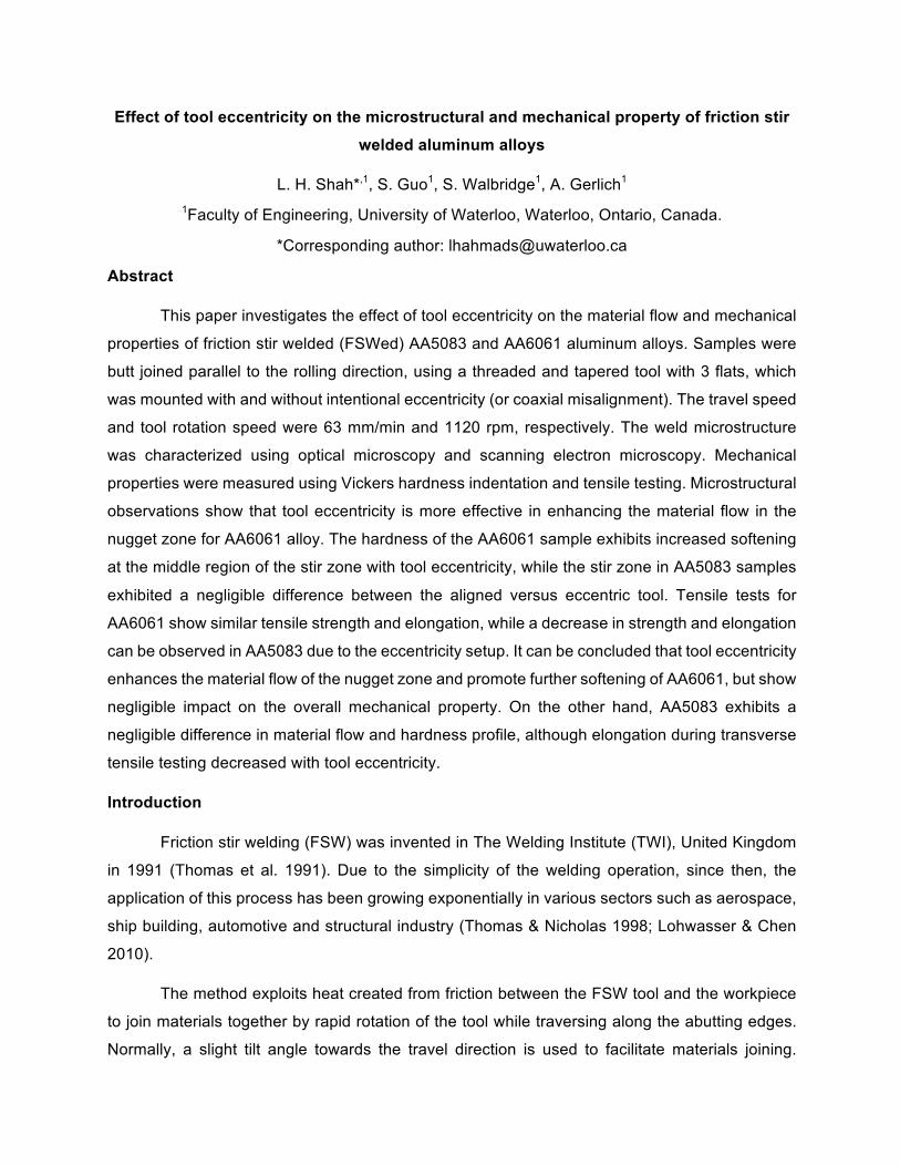
Figure 4 shows the cross-sectional macrograph of specimens etched with Keller’s reagent.
The etching reveals better contrast for AA6061 compared to AA5083 samples. For all specimen,
a clear delineation between the weld region and the base metal can be observed at the advancing
side, while a diffused boundary can be seen at the retreating side. This is a common observation
in cross-sectional macrograph of FSWs (James & Mahoney 1999). The AA6061 specimens show
no observable defects, while the AA5083 specimens show a subsurface void in both aligned and
eccentric samples which had a length of approximately 1 mm and 0.4 mm, respectively.
The AA5083 specimens only show a faint indication of Al foil line near the top region. On
the other hand, a clear distinction can be observed between the Al foil and the surroundings in
AA6061 samples, where the foil exhibits formation of a tortuous line about the periphery of the
weld center and inclined to the advancing side at the crown of the weld. Near the root of the weld
of AA6061 specimens, however, there were no observable foil lines due to the extension of the
white bands from the advancing side of the nugget zone towards the retreating side. Furthermore,
this ‘no foil zone’ is further expanded upwards in the 6061E sample as a consequence to the
expansion of the white bands.
Figure 4. Cross sectional macrograph of (a) 5083A, (b) 5083E, (c) 6061A and (d) 6061E
samples.
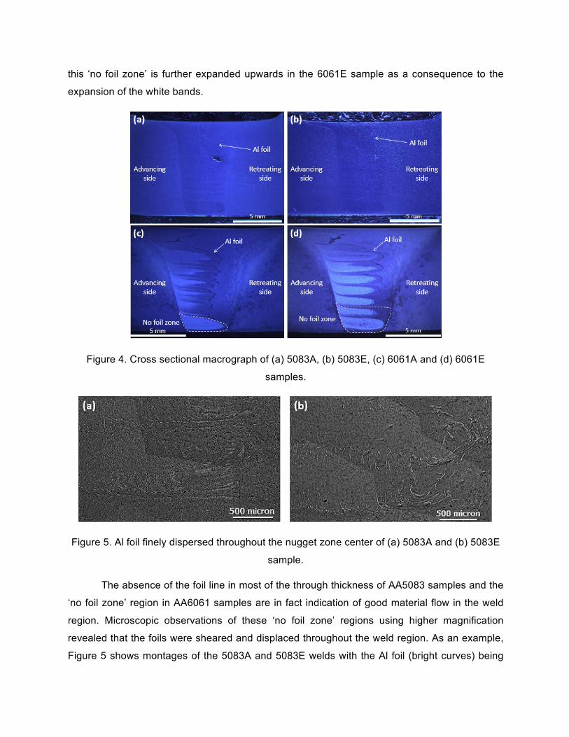
Figure 5. Al foil finely dispersed throughout the nugget zone center of (a) 5083A and (b) 5083E
sample.
The absence of the foil line in most of the through thickness of AA5083 samples and the
‘no foil zone’ region in AA6061 samples are in fact indication of good material flow in the weld
region. Microscopic observations of these ‘no foil zone’ regions using higher magnification
revealed that the foils were sheared and displaced throughout the weld region. As an example,
Figure 5 shows montages of the 5083A and 5083E welds with the Al foil (bright curves) being

finely dispersed in the nugget zone center. While both AA5083 samples show a similar dispersed
Al foil pattern in the weld nugget, the upward extension of the ‘no foil zone’ in 6061E implies that
tool eccentricity enhances the material flow of AA6061.
Figure 6 presents the hardness profile for the top, middle, and bottom cross-sectional
welded regions of AA5083 and AA6061 specimens. The top and bottom region measurements
are taken approximately 1 mm from the sample’s horizontal surface. The advancing side is to the
left of each image, while the retreating side is to the right of each image. The dashed black line is
an approximation of the weld nugget boundary for both cases. For the AA5083 samples, the
overall hardness results show minimal differences between aligned and eccentric sample. On the
other hand, the weld produced with tool eccentricity for AA6061 samples indicates softening
particularly at the middle region of the cross-section, where the observable white bands expanded
towards the center of the weld nugget (Figure 4(d)).
Figure 6. Hardness profile of the top, middle and bottom cross-sectional welded region for
(a) AA5083 samples and (b) AA6061 samples.

5083 alloys are non-heat treatable aluminum alloys, which means that heat treatment
processes do not cause significant changes in the mechanical characteristics of the material. In
contrast, properties of heat treatable aluminum alloys such as AA6061 alloys can be heavily
influenced by heat treatment processes such as during the welding process. This is due to
dissolution of strengthening precipitates due to the heat produced during the welding process
(Sato et al. 1999). Further softening of the region in the eccentricity setup may suggest an
increase in heat input possibly due to increase in material shearing activity. The higher heat input
consequently allows grain growth which softens the lower region (Gerlich et al. 2007).
The average stress-strain curve of the quasi-static tensile tests for all specimen are shown
in Figure 7. All tests were repeated three times and the plotted curves are representatives of each
group. All AA5083 specimens failed at the nugget zone. On the other hand, all 6061A samples
fractured at the heat affected zone (HAZ) of the advancing side. One of the 6061E samples failed
at the same region, while the two other samples failed at the HAZ of retreating side. Failure at the
HAZ region is a common observation in heat-treatable aluminum alloys due to the grain growth
and softening of the HAZ compared to the weld nugget (Mathers 2002).
It can be seen from Figure 7 that there is minimal change in the curve pattern between
6061A and 6061E. On the contrary, a decrease in elongation can be seen in 5083E (5%) sample
compared to 5083A (7%). Furthermore, as presented in Figure 8, 5083E also exhibit a slight
decrease in ultimate tensile strength (UTS), while the 6061E sample shows negligible change as
compared to 6061A. The reason for the decrease in UTS and elongation in AA5083 due to
eccentric setup is currently unclear and further investigation is needed to clarify this phenomenon.
Figure 7. Stress-strain curve for all traverse tensile specimens.

Figure 8. The ultimate tensile strength (UTS) for all specimens with base metals UTS as
reference.
Conclusion
The study of tool eccentricity effects on the material flow and mechanical property of
friction stir welded AA5083 and AA6061 aluminum alloy was successfully conducted. It can be
summarized by the following points:
- Microstructural observations show that tool eccentricity enhances the material flow in the
nugget zone of AA6061 aluminum alloys.
- The Vickers hardness in AA6061 welds exhibit softening at the middle region of the cross
section due to tool eccentricity, while the microhardness of AA5083 welds were not
sensitive to tool eccentricity.
- Tensile tests for AA6061 samples show similar tensile strength and strain behavior, while
AA5083 samples show a slight tensile strength decrease and lower elongation with
eccentricity setup.
- It can be concluded that tool eccentricity enhances the material flow of the nugget zone
and promotes further softening of heat-treatable aluminum alloys, but show negligible
impact on the overall mechanical properties. On the other hand, AA5083 samples show
negligible difference in material flow and hardness profile, but exhibit a slight decrease in
elongation and tensile strength.
Acknowledgements
The authors would like to thank Universiti Malaysia Pahang and Ministry of Higher
Education Malaysia for research funding. Support from the National Sciences and Engineering
Research Council of Canada is also greatly appreciated.
References
Dickerson, T., Shercliff, H.R. & Schmidt, H., 2003. A Weld Marker Technique for Flow
Visualization in Friction Stir Welding. 4th International Symposium on Friction Stir Welding,
(May 2003), pp.14–16.
Gerlich, A., Yamamoto, M. & North, T.H., 2007. Strain Rates and Grain Growth in Al 5754 and
Al 6061 Friction Stir Spot Welds. Metallurgical and Materials Transactions A, 38(6),
pp.1291–1302.
Guerra, M. et al., 2003. Flow patterns during friction stir welding. Materials Characterization, 49,
pp.95–101.
James, M. & Mahoney, M., 1999. Residual stress measurements in friction stir welded
aluminum alloys. In Proceedings of the First International Symposium on Friction Stir
Welding. Thousand Oaks, CA, USA, pp. 14–16.
Leitão, C. et al., 2008. Material flow in Friction Stir Welding. Microscopy and microanalysis,
14(3), pp.87–90.
Lohwasser, D. & Chen, Z., 2010. Friction stir welding: From basics to applications, Cambridge,
England: Woodhead Publishing Limited.
Mathers, G., 2002. The welding of aluminium and its alloys, Cambridge, England: Woodhead
Publishing Limited.
Mishra, R.S. & Ma, Z.Y., 2005. Friction stir welding and processing. Materials Science and
Engineering: R, 50(1–2), pp.1–78. Available at:
http://linkinghub.elsevier.com/retrieve/pii/S0927796X05000768 [Accessed January 22,
2014].
Sato, Y.S. et al., 1999. Microstructural evolution of 6063 aluminum during friction-stir welding.
Metallurgical and Materials Transactions A, 30(9), pp.2429–2437.

Seidel, T.U. & Reynolds, A.P., 2001. Visualization of the material flow in AA2195 friction-stir
welds using a marker insert technique. Metallurgical and Materials Transactions A, 32(11),
pp.2879–2884.
Thomas, W.M. et al., 1991. Friction stir welding.
Thomas, W.M.U. & Nicholas, E.D., 1998. Friction stir welding for the transportation industries.
Materials & Design, 18, pp.269–273.