Effect of Soil Structure Interaction on High Rise Building ...
8
International Journal of Civil and Structural Engineering Research ISSN 2348-7607 (Online) Vol. 6, Issue 1, pp: (165-172), Month: April - September 2018, Available at: www.researchpublish.com Page | 165 Research Publish Journals Effect of Soil Structure Interaction on High Rise Building using ETABS 1 Azra Hanna Razvi J.B., 2 Yashaswini R.K., 3 Arun A.C., 4 Vinay Kumar R., 5 Goutham D.R. 1,2,3,4 Under Graduate student, Adichunchanagiri Institute of Technology, Chikkamagaluru, India 5 Assistant Professor, Adichunchanagiri Institute of Technology, Chikkamagaluru, India Abstract: An asymmetrical R.C.Multi-storey building without infill walls (G+10) with plan irregularity, having four bays in x and y directions located in seismic zones II and III has been analysed with fixed base condition and flexible base condition. Flexible base is achieved by introducing the stiffness of the soil and further the foundation of the building is assumed to be resting on this soil, is called the Winkler’s model approach to incorporate Soil - Structure Interaction to the building. Each individual footing has been designed, depending on the load transferred from column to the footing. Design of footing is carried out based on the IS: 456-2000 code. Using the designed isolated footing parameters, the values of spring stiffness under each column has been calculated using the empirical relationship given in NIST GCR 12-917-21 for assumed values of Modulus of Elasticity and Poisson’s ratio of the soil. Equivalent static method is used in the analysis to take care of earthquake forces as per IS: 1893- 2002. Results have been studied for fixed base and flexible base conditions for both the seismic zones. Conclusions are drawn from the graphs obtained from software tool, such as maximum storey displacement, maximum storey drift and overturning moments. Keywords: R.C.Multi-storey building, Soil-Structure Interaction, Stiffness and Maximum storey displacement. I. INTRODUCTION Most of the civil engineering structures involve some type of structural element with direct contact with ground. When the external forces such as earthquake act on this system, neither the structure displacements nor the ground, displacements are independent of each other. The process in which the response of the soil influences the motion of the structure and the motion of the structure influences the response of the soil is termed as soil structure interaction. A seismic soil-structure interaction analysis evaluates the collective response of the structure, the foundation, and the geologic media underlying and surrounding the foundation, to a specified free-field ground motion. The term free-field refers to motions that are not affected by structural vibrations or the scattering of waves at, and around, the foundation. SSI effects are absent for the theoretical condition of a rigid foundation supported on rigid soil. Accordingly, SSI accounts for the difference between the actual response of the structure and the response of the theoretical, rigid base condition.In present work, an attempt is made to find the detrimental effect of inertial interaction and results are compared for both the fixity conditions, such as fixed base and flexible base. ETABS-2015 is used as an analysis software tool for computing soil structure interaction for high rise buildings subjected to gravity loads, wind forces and seismic forces. Building is modelled in the software with assumed material properties and structural details. The building is assumed to be situated in the seismic prone region, which lies on the seismic zones of II and III [15]. Many works have beencarried out to study the effect of SSI for multi-storey buildings situated under seismic prone regions. [1]Studied the influence of soil structure interaction and design of a 6-storey concrete frame building. Models are simulated under two different conditions: namely soil structure interaction and fixed base behaviour are considered. The influence of the soil structure in the dynamic behaviour of the structure is reflected in an increase in the vibration period as well as increase in the system damping in comparison with the fixed base model, which does not consider the supporting soil. And the author had proposed a design spectrum considering a critical damping of 13% consistent with the
Transcript of Effect of Soil Structure Interaction on High Rise Building ...
International Journal of Civil and Structural Engineering Research ISSN 2348-7607 (Online) Vol. 6, Issue 1, pp: (165-172), Month: April - September 2018, Available at: www.researchpublish.com
Page | 165 Research Publish Journals
Effect of Soil Structure Interaction on High
Rise Building using ETABS
1Azra Hanna Razvi J.B.,
2Yashaswini R.K.,
3Arun A.C.,
4Vinay Kumar R.,
5Goutham D.R.
1,2,3,4 Under Graduate student, Adichunchanagiri Institute of Technology, Chikkamagaluru, India
5Assistant Professor, Adichunchanagiri Institute of Technology, Chikkamagaluru, India
Abstract: An asymmetrical R.C.Multi-storey building without infill walls (G+10) with plan irregularity, having
four bays in x and y directions located in seismic zones II and III has been analysed with fixed base condition and
flexible base condition. Flexible base is achieved by introducing the stiffness of the soil and further the foundation
of the building is assumed to be resting on this soil, is called the Winkler’s model approach to incorporate Soil-
Structure Interaction to the building. Each individual footing has been designed, depending on the load
transferred from column to the footing. Design of footing is carried out based on the IS: 456-2000 code. Using the
designed isolated footing parameters, the values of spring stiffness under each column has been calculated using
the empirical relationship given in NIST GCR 12-917-21 for assumed values of Modulus of Elasticity and Poisson’s
ratio of the soil. Equivalent static method is used in the analysis to take care of earthquake forces as per IS: 1893-
2002. Results have been studied for fixed base and flexible base conditions for both the seismic zones. Conclusions
are drawn from the graphs obtained from software tool, such as maximum storey displacement, maximum storey
drift and overturning moments.
Keywords: R.C.Multi-storey building, Soil-Structure Interaction, Stiffness and Maximum storey displacement.
I. INTRODUCTION
Most of the civil engineering structures involve some type of structural element with direct contact with ground. When the
external forces such as earthquake act on this system, neither the structure displacements nor the ground, displacements
are independent of each other. The process in which the response of the soil influences the motion of the structure and the
motion of the structure influences the response of the soil is termed as soil structure interaction. A seismic soil-structure
interaction analysis evaluates the collective response of the structure, the foundation, and the geologic media underlying
and surrounding the foundation, to a specified free-field ground motion. The term free-field refers to motions that are not
affected by structural vibrations or the scattering of waves at, and around, the foundation. SSI effects are absent for the
theoretical condition of a rigid foundation supported on rigid soil. Accordingly, SSI accounts for the difference between
the actual response of the structure and the response of the theoretical, rigid base condition.In present work, an attempt is
made to find the detrimental effect of inertial interaction and results are compared for both the fixity conditions, such as
fixed base and flexible base. ETABS-2015 is used as an analysis software tool for computing soil structure interaction for
high rise buildings subjected to gravity loads, wind forces and seismic forces. Building is modelled in the software with
assumed material properties and structural details. The building is assumed to be situated in the seismic prone region,
which lies on the seismic zones of II and III [15].
Many works have beencarried out to study the effect of SSI for multi-storey buildings situated under seismic prone
regions. [1]Studied the influence of soil structure interaction and design of a 6-storey concrete frame building. Models are
simulated under two different conditions: namely soil structure interaction and fixed base behaviour are considered. The
influence of the soil structure in the dynamic behaviour of the structure is reflected in an increase in the vibration period
as well as increase in the system damping in comparison with the fixed base model, which does not consider the
supporting soil. And the author had proposed a design spectrum considering a critical damping of 13% consistent with the

International Journal of Civil and Structural Engineering Research ISSN 2348-7607 (Online) Vol. 6, Issue 1, pp: (165-172), Month: April - September 2018, Available at: www.researchpublish.com
Page | 166 Research Publish Journals
structural behaviour expected and according with the recommendation of the regulations has been proposed.[3]They had
studied and suggested that the effect of soil-structure interaction is generally ignored in the design process of low-rise
buildings resting on shallow foundations, though it has been shown that ignoring such effect may lead to unsafe seismic
design. They had observed that the fundamental natural frequencies increase and base shear decrease with the increase of
soil stiffness and this change is found more in soft soils.[4]The authors had studied that tall asymmetric buildings
experience more risk during the earthquakes (Ming, 2010). This happens mainly due to attenuation of earthquake waves
and local site response which get transferred to the structure and vice versa. This can be well explained by the dynamic
soil structure interaction analysis. Authors have been concluded that for the given ground motion the displacement
increases as from soil mass to superstructure in both X and Y direction, but this change is very minute for the vertical
direction displacement.
A. Objectives:
The following are the objectives of the present work, they are
1) To study the effect of SSI on R.C.Multi-storey building for seismic zones II and III.
2) To compare the behaviour of R.C.Multi-storey building under fixed base condition and flexible base condition, the
study investigates the parameters such as, maximum storey displacement, maximum storey drift and overturning
moment.
II. METHODOLOGY

International Journal of Civil and Structural Engineering Research ISSN 2348-7607 (Online) Vol. 6, Issue 1, pp: (165-172), Month: April - September 2018, Available at: www.researchpublish.com
Page | 167 Research Publish Journals
A. Building Configuration:
The following material properties and sectional properties are assumed to model the high rise building in the software.
Grade of concrete: M30
Characteristic yield strength of steel: Fe415
Number of storey: G + 10
Storey height : Ground floor: 4.2 m , Other floors: 3.2 m
Size of column: (600×450)mm
Size of beam: (500×300)mm
Slab thickness: 175 mm
Intensity of live load: 2 kN/m2
Intensity of floor finish: 0.75 kN/m2
Fig 1: Three dimensional views of R.C.Multi-storey building with fixed base and flexible base
B. Load Combinations:
Indian code specifies [14], [15] the following load cases with partial safety factors under limit state design method. When
a structural building is subjected to live load, wind load and seismic forces in addition to its self-weight, the load
combinations are to be taken as follows,
1.5(DL+LL)
1.2(DL+LL+ELx or WLx)
1.2(DL+LL+ELyor WLy)
1.2(DL+LL-ELxor WLx)
1.2(DL+LL-ELyor WLy)
1.5(DL+ELxor WLx)
1.5(DL-ELxor WLx)
1.5(DL+ELyor WLy)
1.5(DL-ELyor WLy)
0.9DL+1.5ELx

International Journal of Civil and Structural Engineering Research ISSN 2348-7607 (Online) Vol. 6, Issue 1, pp: (165-172), Month: April - September 2018, Available at: www.researchpublish.com
Page | 168 Research Publish Journals
0.9DL-1.5ELx
0.9DL+1.5ELy
0.9DL-1.5ELy
C. Equivalent Static Method of Analysis:
The equivalent static lateral force method is a simplified technique to substitute the effect of dynamic loading of an
expected earthquake by a static force distributed laterally on a structure for design purposes. Earthquake motion causes
vibration of the structure leading to inertia forces [9]. Thus a structure must be able to safely transmit the horizontal and
vertical inertia of forces generated in the super structure through the foundation to the ground. For calculation of design
horizontal seismic coefficient, the equations 1.1 and 1.2 are used.
Vb = Ah × W ...... (1.1)
Where,
Ah= (
) (
) (
) ...... (1.2)
W = Total weight of the building.
Zone factor (Z)[15]: 0.1
Importance factor (I)[15]: 1
Response reduction factor (R)[15]: 5
D. Spring Stiffness:
To calculate the spring stiffness, empirical equations given in table - I is used. The equations are mentioned in [7] NIST
GCR 12-917-21, Soil Structure Interaction for Building Structures.
TABLE I: ELASTIC SOLUTIONS FOR STATIC STIFFNESS OF RIGID FOOTINGS AT THE GROUND SURFACE
Degree of freedom Stiffness of foundation soil
Translation along x-axis Kx =
(
)
+ 2.4]
Translation along y-axis Ky=
(
)
+ 0.8 (
)
Translation along z-axis Kz=
(
)
+ 1.6]
Rocking about x-axis Kxx=
(
) + 0.8]
Rocking about y-axis Kyy=
(
)
+ 0.27]
Torsion about z-axis Kzz= (
)
+ 4.06]
From the Table-I,
L = Length of the footing.
B= Breadth of the footing.
G =Modulus of Rigidity.
v = µ = Poisson‟s ratio.
Modulus of elasticity, E = 80N/mm²
Poisson‟s ratio, µ = 0.3
In present work, the values of Modulus of elasticity (E) and Poisson‟s ratio (µ) of soil surrounding the footing are
assumed suitably from [8]. Footing sizes are designed for each column axial load and they had checked for safety
according to the IS code [11]. Using the „E‟ and „µ‟ values of assumed soil type, the stiffness values are calculated and
they are assigned as flexible springs at all column bases replacing rigid base. With the designed values of length and

International Journal of Civil and Structural Engineering Research ISSN 2348-7607 (Online) Vol. 6, Issue 1, pp: (165-172), Month: April - September 2018, Available at: www.researchpublish.com
Page | 169 Research Publish Journals
breadth of footing, the spring stiffness is worked out. Nineteen individual springs are defined in the software and they are
assigned to corresponding column base to achieve the flexible base. Table - II shows the values of spring constants based
on their translations (Kx, Ky and Kz) to be expected in three direction and rotations (Kxx, Kyy and Kzz) in three directions.
Fig 2: Numbering of the columns
TABLE II: SPRING STIFFNESS AT ALL COLUMN BASES
III. RESULTS AND DISCUSSIONS
As per the results obtained from the software tool, the following numerical values have been drawn and they are
compared. The table - III and table - IV gives the various parameters of the building with fixed base condition and flexible
base condition over two seismic regions. The values are extracted across different storey level. Further they are
represented in the form of graphs.
Column No. Pu
(kN)
L
(mm)
B
(mm)
Kx
(10³
N/mm)
Ky
(10³
N/mm)
Kz
(10³
N/mm)
Kxx
(1011
N-mm/rad)
Kyy
(1011
N-mm/rad)
Kzz
(1011
N-mm/rad)
1 1269.260 2500 1900 181.03 185.37 225.85 1.88 2.84 3.27
2 2001.651 3100 2300 221.81 227.60 276.90 3.41 5.32 6.03
3 2001.48 3100 2300 221.81 227.60 276.90 3.41 5.32 6.03
4 1268.085 2500 1900 181.03 185.37 225.85 1.88 2.84 3.26
5 1965.014 3100 2300 221.81 227.60 276.90 3.42 5.32 6.03
6 3222.185 4000 3000 287.74 294.98 359.12 7.51 1.15 13.1
7 3222.170 4000 3000 287.74 294.98 359.12 7.51 1.15 13.1
8 1963.976 3100 2300 221.81 227.60 276.90 3.41 5.32 6.03
9 1927.827 3100 2300 221.81 227.60 276.90 3.41 5.32 6.03
10 3200.233 4000 3000 287.74 294.98 359.12 7.51 11.5 13.1
11 3198.468 4000 3000 287.74 294.98 359.12 7.51 11.5 13.1
12 1924.414 2800 2100 201.42 206.48 251.38 2.57 3.95 4.51
13 1633.267 2800 2100 201.42 206.48 251.38 2.57 3.95 4.51
14 2719.438 3600 2700 258.97 265.48 323.21 5.47 8.41 9.59
15 2332.597 3400 2500 242.19 248.70 302.43 4.42 6.98 7.86
16 1158.137 2400 1800 177.37 176.98 215.47 1.62 2.49 2.83
17 707.8027 1900 1400 135.48 139.10 169.17 7.75 1.22 1.38
18 1161.341 2400 1800 172.64 176.98 215.47 1.62 2.49 2.83
19 708.7931 1900 1400 135.48 139.10 169.17 7.75 1.22 1.38

International Journal of Civil and Structural Engineering Research ISSN 2348-7607 (Online) Vol. 6, Issue 1, pp: (165-172), Month: April - September 2018, Available at: www.researchpublish.com
Page | 170 Research Publish Journals
TABLE III: MAXIMUM STOREY DISPLACEMENT, MAXIMUM STOREY DRIFT AND OVERTURNING MOMENT
VALUES OF A BUILDING WITH FIXED BASE CONDITION
Sl.No.
Storey
Max., Storey
Displacement (mm)
Max., Storey Drift Overturning Moments
(kN-m)
Z = 0.1 Z = 0.16 Z = 0.1 Z = 0.16 Z = 0.1 Z = 0.16
1 Story10 2.4 3.9 0.000379 0.000379 6204.136 6204.136
2 Story9 1.8 2.9 0.000153 0.000153 23374.12 19999.12
3 Story8 1.5 2.4 0.000014 0.000014 50221.57 41446.57
4 Story7 1.4 2.2 0.000012 0.000012 78040.74 63865.74
5 Story6 1.2 1.9 0.000031 0.000031 105859.9 86284.9
6 Story5 0.9 1.5 0.000063 0.000063 141521.5 114746.5
7 Story4 0.8 1.2 0.000044 0.000044 178154.9 144179.9
8 Story3 0.5 0.9 0.000032 0.000032 214788.2 173613.2
9 Story2 0.3 0.5 0.000022 0.000022 251421.6 203046.6
10 Story1 0.1 0.2 0.000008 0.000008 288055 232480
11 Base 0 0 0 0 292913.5 237338.5
TABLE IV: MAXIMUM STOREY DISPLACEMENT, MAXIMUM STOREY DRIFT AND OVERTURNING MOMENT
VALUES OF A BUILDING WITH FLEXIBLE BASE CONDITION
Sl.No. Storey Max., Storey
Displacement (mm)
Max., Storey Drift Overturning Moments
(kN-m)
Z = 0.1 Z = 0.16 Z = 0.1 Z = 0.16 Z = 0.1 Z = 0.16
1 Story10 3.3 4.2 0.000539 0.000539 6204.136 6204.136
2 Story9 1.9 2.8 0.000258 0.000258 23374.12 23374.12
3 Story8 1.2 2.1 0.000046 0.000046 50221.57 50221.57
4 Story7 0.9 1.7 0.000056 0.000056 78040.74 78040.74
5 Story6 0.6 1.3 0.000042 0.000042 105859.9 105859.9
6 Story5 0.3 0.9 0.000095 0.000095 141521.5 141521.5
7 Story4 0.3 0.8 0.000082 0.000082 178154.9 178154.9
8 Story3 0.2 0.6 0.000071 0.000071 214788.2 214788.2
9 Story2 0.2 0.4 0.000055 0.000055 251421.6 251421.6
10 Story1 0.1 0.2 0.000056 0.000056 288055 288055
11 Base 0.1 0.1 0 0 292913.5 292913.5
Graph 1.1: Maximum storey displacement for fixed and flexible base
0
1
2
3
4
5
Sto
ry1
0
Sto
ry9
Sto
ry8
Sto
ry7
Sto
ry6
Sto
ry5
Sto
ry4
Sto
ry3
Sto
ry2
Sto
ry1
Bas
e
Dis
pla
cem
ent
mm
Storey
Maximum Storey displacement for fixed
base
Z=0.1
Z=0.16
0
1
2
3
4
5
Sto
ry1
0
Sto
ry9
Sto
ry8
Sto
ry7
Sto
ry6
Sto
ry5
Sto
ry4
Sto
ry3
Sto
ry2
Sto
ry1
Bas
e
Dis
pla
cem
ent
mm
Storey
Maximum Storey displacement for flexible
base
Z=0.1
Z=0.16
International Journal of Civil and Structural Engineering Research ISSN 2348-7607 (Online) Vol. 6, Issue 1, pp: (165-172), Month: April - September 2018, Available at: www.researchpublish.com
Page | 171 Research Publish Journals
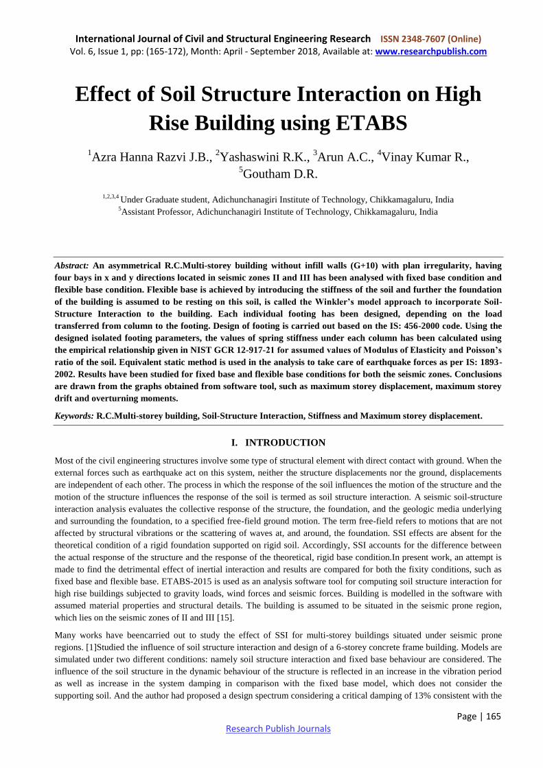
Graph 1.2: Maximum storey drift for fixed and flexible base
Graph 1.3: Maximum overturning moment for fixed and flexible base
IV. CONCLUSION
1) The maximum storey displacement for fixed base at storey-10 works out to be 3.9 mm for z = 0.16 and 2.4 mm for z =
0.10. And for flexible base these values changes to 4.2 mm for z =0.16 and 3.2mm for z = 0.10 at the same storey
level. There is an increase in the values of storey displacement when building with SSI effect is considered.
2) The maximum storey drift for fixed base is 0.000397 at 10th storey for both the seismic zones. And for flexible base
0.000539 at the same storey height, which is higher compared to fixed base.
3) The maximum overturning moments for fixed base condition at base level for z = 0.16 is 237338.51 kN-m and for z =
0.10 the value is 292913.51 kN-m. For flexible base, these values on z = 0.16 and 0.10 is 292913.518 kN-m. It may be
also noted that the overturning moment is abundant at the base level of the building in comparison to the top storey.
4) From above three outcomes, it is possible to conclude that, the maximum storey displacement and maximum storey
drift have significantly changed with higher values when SSI effect is considered.
5) There is no drastic change in the overturning moments with flexible base condition compared with fixed base
condition.
REFERENCES
[1] Julio, “Soil structure interaction in the analysis and seismic design of reinforced concrete frame buildings”. The 14th
World Conference on Earthquake Engineering, issue: 12-17th
October, 2008, Beijing, China.
[2] Suresh Dash et.al, “P-Y curves to model lateral response of pile foundation in liquefied soils”. The 14th World
Conference on Earthquake engineering, issue: 12-17 October, 2008, Beijing, China.
[3] Amar and Dyavanal, “Seismic soil structure interaction of building with rigid and flexible foundation”. International
Journal of science and research, issue: 2013.
0
0.0001
0.0002
0.0003
0.0004
Sto
ry1
0
Sto
ry9
Sto
ry8
Sto
ry7
Sto
ry6
Sto
ry5
Sto
ry4
Sto
ry3
Sto
ry2
Sto
ry1
Bas
e
Dri
ft
Storey
Maximum storey drift for fixed base
Z=0.1
Z=0.16
0
0.0001
0.0002
0.0003
0.0004
0.0005
0.0006
Sto
ry1
0St
ory
9St
ory
8St
ory
7St
ory
6St
ory
5St
ory
4St
ory
3St
ory
2St
ory
1B
ase
Dri
ft
Storey
Maximum Storey drift for flexible base
z=0.1
z=0.16
0
100000
200000
300000
400000
Sto
ry1
0
Sto
ry9
Sto
ry8
Sto
ry7
Sto
ry6
Sto
ry5
Sto
ry4
Sto
ry3
Sto
ry2
Sto
ry1
Bas
eOver
turn
ing m
om
ent
kN
-m
Storey
Maximum overturning moment for fixed
base
Z=0.1
Z=0.16
050000
100000150000200000250000300000350000
Sto
ry1
0
Sto
ry9
Sto
ry8
Sto
ry7
Sto
ry6
Sto
ry5
Sto
ry4
Sto
ry3
Sto
ry2
Sto
ry1
Bas
e
Over
turn
ing m
om
rnt
kN
-m
Storey
Maximum overturning moment for flexible
base
z=0.1
z=0.16

International Journal of Civil and Structural Engineering Research ISSN 2348-7607 (Online) Vol. 6, Issue 1, pp: (165-172), Month: April - September 2018, Available at: www.researchpublish.com
Page | 172 Research Publish Journals
[4] Pallavi Ravishankar and Neelima, “Numerical modelling to study soil structure interaction for tall asymmetrical
building”. International Conference on Earthquake Geotechnical Engineering, Istanbul, Turkey, issue: June, 2013.
[5] Varikuppala Krishna et.al, “Analysis and Design of Multi Storied Building by Using ETABS Software.”
[6] Chaitanya Kumar J.D and Lute Venkat, “Analysis of multi storey building with precast load bearing walls.”
[7] “Soil-Structure Interaction for Building Structures”, National Institute of Standards and Technology, NIST GCR 12-
917-21, U.S. Department of Commerce.
[8] “Advanced Soil Mechanics”, Third Edition, Braja M.Das, Taylor and Francis.
[9] “Earthquake Resistant Design of Structures”, Pankaj Agarwal and Manish Shrikhande, PHI learning Private Limited.
[10] “Limit State Design of Reinforced Concrete”, Second Edition, P.C.Varghese, Prentice Hall of India Private Limited.
[11] “Plain and Reinforced Concrete – Code of Practice”, IS 456: 2000, Bureau of Indian Standards.
[12] “Design loads (Other than earthquake for buildings and structure) – Code of Practice”, IS: 875 (Part 1)-1987(Dead
Loads), Bureau of Indian Standards.
[13] “Design loads (Other than earthquake for buildings and structure) – Code of Practice”, IS: 875 (Part 2)-1987
(Imposed loads), Bureau of Indian Standards.
[14] “Code of Practice for Design Loads (Other than earthquake for buildings and structure)”, IS: 875 (Part 3)-1987
(Wind Forces), Bureau of Indian Standards.
[15] “Criteria for Earthquake Resistant Design of Structures”, IS 1893 (Part 1): 2002, Bureau of Indian Standards.