Effect of Shape and Size on Fiber Reinforced Polymer Composite Wrapped Concrete Columns
14
Effect of Shape and Size on Fiber Reinforced Polymer Composite Wrapped Concrete Columns Dr. Abhay Bambole, Professor and Head, SPCE, Mumbai Kedar Joshi, Post Graduate Student, SPCE, Mumbai Abstract: Rehabilitation of structures with FRP composites has proved to be cost effective method of enhancing the service life of structures. FRP composites are used for retrofitting and Rehabilitation of Columns and Bridge Piers. The shapes of the columns have a significant effect on confining strength of FRP Wraps. A lot of research has been carried out around the globe varying different parameters and finding usable data. This paper presents results of axial compression test conducted on over two hundred and forty concrete specimens having circular, square and rectangular cross sections. The effect of shapes, sizes and shape modification of the cross sections on the load carrying capacity of FRP wrapped concrete prisms and cylinders, has been studied. The project also studies the effect of shape modifications on enhancement in load carrying capacity in case of non circular cross section. Investigation was done on rectangular columns to increase the confinement effectiveness by modifying it into elliptical cross-sections. All the experimental results were compared with analytical values calculated as per the ACI-440.2R-08 code. The results of experiments and comparison are presented. Keywords: FRP, Fibre reinforced polymer, Shape, Size, Strengthening, Column INTRODUCTION In construction industry, over the last two decades, Fiber Reinforced Polymer (FRP) composites have become a primary choice for strengthening buildings and bridge components because of their high strength to weight ratio and stiffness-to-weight ratios, ease of application, cost effectiveness and such other salient traits. FRP composites are also considered as excellent substitutes for building components like concrete bridge decks, reinforcing bars and pre-stressing materials. These FRP composites are widely used for retrofitting and rehabilitation of building columns and bridge piers. Confinement of columns by means of FRP jackets is done by containing the dilation of concrete by wrapping the fibers in the hoop direction of concrete columns. In past decade research has been carried out taking into account possible parameters in strengthening using FRP wrapping. Mirmiran et al, tested fifty four concrete filled FRP tubes in uniaxial compression under displacement control mode to study the dilation characteristics of confined concrete. They found that the dilation rate finally stabilizes at an ultimate value which is a function of the jacket's stiffness 1 . Tan et al tested to failure fifty two half scale rectangular columns with aspect ratio 3.65 under a concentric load to investigate the effect of fiber type configuration and fiber anchors on the strength enhancement of the columns 2 . Pan et al performed axial compression test on six FRP wrapped slender rectangular columns modified to elliptical shape having slenderness ratio L/b ranging from 4.5 to 17.5. The strengthening effect of FRP was observed to be decreasing with the increase in the slenderness ratio 3 . Yousef et al studied factors such as ultimate stress, rupture strain, jacket parameters, and cross-sectional geometry affecting the stress–strain behavior of FRP- confined concrete 4 . Silva et al studied the environmental effects such as humidity, UV rays, exposure to moisture, salt fogs, thermal cycles on mechanical properties of GFRP laminates and consequently on
-
Upload
ajith-chandran -
Category
Documents
-
view
21 -
download
2
description
effect of fibre reinforced polymer based on size and shape
Transcript of Effect of Shape and Size on Fiber Reinforced Polymer Composite Wrapped Concrete Columns
Effect of Shape and Size on Fiber Reinforced Polymer Composite
Wrapped Concrete Columns Dr. Abhay Bambole, Professor and Head, SPCE, Mumbai
Kedar Joshi, Post Graduate Student, SPCE, Mumbai
Abstract: Rehabilitation of structures with FRP composites has proved to be cost effective method of enhancing the service life of
structures. FRP composites are used for retrofitting and Rehabilitation of Columns and Bridge Piers. The shapes of the
columns have a significant effect on confining strength of FRP Wraps. A lot of research has been carried out around the
globe varying different parameters and finding usable data. This paper presents results of axial compression test
conducted on over two hundred and forty concrete specimens having circular, square and rectangular cross sections.
The effect of shapes, sizes and shape modification of the cross sections on the load carrying capacity of FRP wrapped
concrete prisms and cylinders, has been studied. The project also studies the effect of shape modifications on
enhancement in load carrying capacity in case of non circular cross section. Investigation was done on rectangular
columns to increase the confinement effectiveness by modifying it into elliptical cross-sections. All the experimental
results were compared with analytical values calculated as per the ACI-440.2R-08 code. The results of experiments and
comparison are presented.
Keywords: FRP, Fibre reinforced polymer, Shape, Size, Strengthening, Column
INTRODUCTION
In construction industry, over the last two decades, Fiber Reinforced Polymer (FRP) composites have
become a primary choice for strengthening buildings and bridge components because of their high strength
to weight ratio and stiffness-to-weight ratios, ease of application, cost effectiveness and such other salient
traits. FRP composites are also considered as excellent substitutes for building components like concrete
bridge decks, reinforcing bars and pre-stressing materials. These FRP composites are widely used for
retrofitting and rehabilitation of building columns and bridge piers. Confinement of columns by means of
FRP jackets is done by containing the dilation of concrete by wrapping the fibers in the hoop direction of
concrete columns.
In past decade research has been carried out taking into account possible parameters in strengthening using
FRP wrapping. Mirmiran et al, tested fifty four concrete filled FRP tubes in uniaxial compression under
displacement control mode to study the dilation characteristics of confined concrete. They found that the
dilation rate finally stabilizes at an ultimate value which is a function of the jacket's stiffness 1. Tan et al tested
to failure fifty two half scale rectangular columns with aspect ratio 3.65 under a concentric load to investigate
the effect of fiber type configuration and fiber anchors on the strength enhancement of the columns2. Pan et
al performed axial compression test on six FRP wrapped slender rectangular columns modified to elliptical
shape having slenderness ratio L/b ranging from 4.5 to 17.5. The strengthening effect of FRP was observed
to be decreasing with the increase in the slenderness ratio3. Yousef et al studied factors such as ultimate stress,
rupture strain, jacket parameters, and cross-sectional geometry affecting the stress–strain behavior of FRP-
confined concrete4. Silva et al studied the environmental effects such as humidity, UV rays, exposure to
moisture, salt fogs, thermal cycles on mechanical properties of GFRP laminates and consequently on
strengthened columns5. Benzaid et al experimentally scrutinized the effects of increasing the corner radius and
the no of GFRP layers on the confined compressive strength of square columns6.
Shape of cross section, corner radius, grade of concrete, FRP volumetric ratio are some of the important
factors that affect the confinement effectiveness of FRP wraps. The experiments presented here were
formulated to make a comprehensive study to determine the extent these parameters can be used to enhance
the load carrying capacity in case of non-circular columns.
Confining pressure for cylinders
In case of cylinders the whole cross sectional area is effectively confined because the confining pressure is
uniformly distributed along the perimeter as shown in fig 1. The behavior of confined cylinders is similar to a
thin walled cylinder. The equation for confining pressure7 is given as,
2
frpfrp frpl
Eρf
ε= (1a)
Where, Efrp = Young’s modulus of FRP wraps
εfrp = strain in FRP wraps at failure
ρfrp = FRP volumetric ratio
ρfrp = 4/.
...2d
tnd f
ππ
(1b)
where, d = diameter of cross section
n = no of layers
tf = thickness of FRP wrap
Confining pressure for non circular cross sections
In case of non circular cross sections the confining pressure is affected by the sharp edges. The dilation in
non circular cross section is effectively contained by the FRP wraps only at the corners due to stress
concentration as shown in fig 2. The effective confined area is reduced because stress concentration causes
arching of concrete core along the sides. The equation for confining pressure for non circular cross section is
given as7,
2
frpfrp frpal
Eρkf
ε= (2a)
In order to account for the reduced effective confined area, the confining pressure is reduced by a shape
factor ka1 and is given by the following equation,
ka =
2b
hA
A
c
e (2b)
where, Ae/Ac =
( )
g
ggA
rbb
hrh
h
b
ρ
ρ
−
−−+−
−
1
3
)2( 2 1
22
(2c)
in which, ρg = ratio of area of steel to gross cross sectional area
The FRP volumetric ratio is given as,
bh
hbtn f ).(..2 + (2d)
Confining pressure for elliptical cross sections:
Shape modification of rectangular cross section to elliptical shapes is one of the effective method to increase
the confining pressure provided by the FRP wraps. The confined compressive strength for elliptically
modified non circular cross section is given as8,
lcocc fa
bff
22''
+= (3a)
In the above equation for confining pressure is same as eq. (1a). The FRP volumetric ratio for elliptical cross
section is given as following8,
ab
tabb) - (a. f
frpρ]51[ +
= (3b)
EXPERIMENTAL WORK
The primary aim of this experiment was to study the effects of shapes, sizes and shape modification (corners)
on the confinement effectiveness of the FRP wraps and to achieve maximum confinement. The grade of
concrete and the height on specimen was kept as M30 and 300mm for all specimen. The specimen were
casted in the following manner.
1. For all the three cases i.e. circular, square and rectangular specimens were casted in three sizes in
increasing order of the cross sections as shown in Table 1.
2. In the case of rectangular and square columns the cross sections were carefully decided so that each
square column has a corresponding rectangular column having the same cross-sectional area.
3. The size of the rectangular columns were chosen in such a way that the aspect ratio is equal to 1.5 or
greater than 1.5. This is to take care of the effect of aspect ratio in rectangular columns.
All specimens were wrapped with one layer of glass fiber wraps. Glass fibers had an ultimate strength of
2400 MPa, elastic modulus of 80 kN/mm2 and a density of 2.78 g/cc as per manufacturer’s data sheet (R&M
International Pvt. Ltd., Mumbai). Resin epoxy was used as matrix and had two component (base and
hardener) mixed in the ratio of 100:35 as suggested by the manufacturer. All specimens were pretreated with
resin primer in order to achieve a smooth surface and good bond between FRP and the specimen surface.
FRP wraps were applied to both sharp edged and rounded edged prisms. The rounded edged non circular
prisms had a corner radius of 37.5 mm. Rectangular prisms were also modified to elliptical shapes before FRP
wrapping by placing them in elliptical moulds.
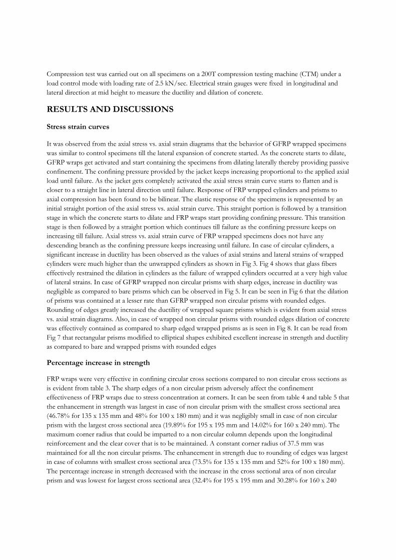
Compression test was carried out on all specimens on a 200T compression testing machine (CTM) under a
load control mode with loading rate of 2.5 kN/sec. Electrical strain gauges were fixed in longitudinal and
lateral direction at mid height to measure the ductility and dilation of concrete.
RESULTS AND DISCUSSIONS
Stress strain curves
It was observed from the axial stress vs. axial strain diagrams that the behavior of GFRP wrapped specimens
was similar to control specimens till the lateral expansion of concrete started. As the concrete starts to dilate,
GFRP wraps get activated and start containing the specimens from dilating laterally thereby providing passive
confinement. The confining pressure provided by the jacket keeps increasing proportional to the applied axial
load until failure. As the jacket gets completely activated the axial stress strain curve starts to flatten and is
closer to a straight line in lateral direction until failure. Response of FRP wrapped cylinders and prisms to
axial compression has been found to be bilinear. The elastic response of the specimens is represented by an
initial straight portion of the axial stress vs. axial strain curve. This straight portion is followed by a transition
stage in which the concrete starts to dilate and FRP wraps start providing confining pressure. This transition
stage is then followed by a straight portion which continues till failure as the confining pressure keeps on
increasing till failure. Axial stress vs. axial strain curve of FRP wrapped specimens does not have any
descending branch as the confining pressure keeps increasing until failure. In case of circular cylinders, a
significant increase in ductility has been observed as the values of axial strains and lateral strains of wrapped
cylinders were much higher than the unwrapped cylinders as shown in Fig 3. Fig 4 shows that glass fibers
effectively restrained the dilation in cylinders as the failure of wrapped cylinders occurred at a very high value
of lateral strains. In case of GFRP wrapped non circular prisms with sharp edges, increase in ductility was
negligible as compared to bare prisms which can be observed in Fig 5. It can be seen in Fig 6 that the dilation
of prisms was contained at a lesser rate than GFRP wrapped non circular prisms with rounded edges.
Rounding of edges greatly increased the ductility of wrapped square prisms which is evident from axial stress
vs. axial strain diagrams. Also, in case of wrapped non circular prisms with rounded edges dilation of concrete
was effectively contained as compared to sharp edged wrapped prisms as is seen in Fig 8. It can be read from
Fig 7 that rectangular prisms modified to elliptical shapes exhibited excellent increase in strength and ductility
as compared to bare and wrapped prisms with rounded edges
Percentage increase in strength
FRP wraps were very effective in confining circular cross sections compared to non circular cross sections as
is evident from table 3. The sharp edges of a non circular prism adversely affect the confinement
effectiveness of FRP wraps due to stress concentration at corners. It can be seen from table 4 and table 5 that
the enhancement in strength was largest in case of non circular prism with the smallest cross sectional area
(46.78% for 135 x 135 mm and 48% for 100 x 180 mm) and it was negligibly small in case of non circular
prism with the largest cross sectional area (19.89% for 195 x 195 mm and 14.02% for 160 x 240 mm). The
maximum corner radius that could be imparted to a non circular column depends upon the longitudinal
reinforcement and the clear cover that is to be maintained. A constant corner radius of 37.5 mm was
maintained for all the non circular prisms. The enhancement in strength due to rounding of edges was largest
in case of columns with smallest cross sectional area (73.5% for 135 x 135 mm and 52% for 100 x 180 mm).
The percentage increase in strength decreased with the increase in the cross sectional area of non circular
prism and was lowest for largest cross sectional area (32.4% for 195 x 195 mm and 30.28% for 160 x 240
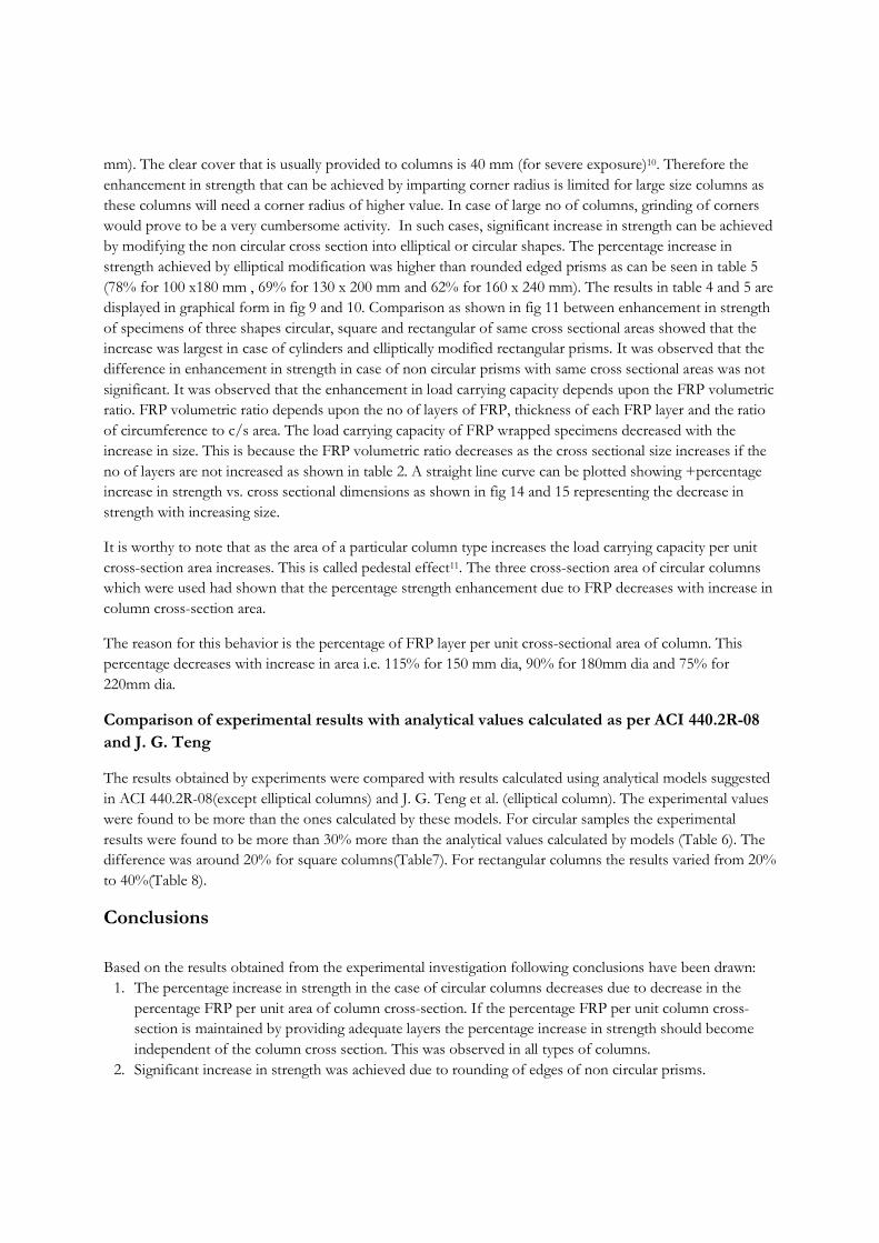
mm). The clear cover that is usually provided to columns is 40 mm (for severe exposure)10. Therefore the
enhancement in strength that can be achieved by imparting corner radius is limited for large size columns as
these columns will need a corner radius of higher value. In case of large no of columns, grinding of corners
would prove to be a very cumbersome activity. In such cases, significant increase in strength can be achieved
by modifying the non circular cross section into elliptical or circular shapes. The percentage increase in
strength achieved by elliptical modification was higher than rounded edged prisms as can be seen in table 5
(78% for 100 x180 mm , 69% for 130 x 200 mm and 62% for 160 x 240 mm). The results in table 4 and 5 are
displayed in graphical form in fig 9 and 10. Comparison as shown in fig 11 between enhancement in strength
of specimens of three shapes circular, square and rectangular of same cross sectional areas showed that the
increase was largest in case of cylinders and elliptically modified rectangular prisms. It was observed that the
difference in enhancement in strength in case of non circular prisms with same cross sectional areas was not
significant. It was observed that the enhancement in load carrying capacity depends upon the FRP volumetric
ratio. FRP volumetric ratio depends upon the no of layers of FRP, thickness of each FRP layer and the ratio
of circumference to c/s area. The load carrying capacity of FRP wrapped specimens decreased with the
increase in size. This is because the FRP volumetric ratio decreases as the cross sectional size increases if the
no of layers are not increased as shown in table 2. A straight line curve can be plotted showing +percentage
increase in strength vs. cross sectional dimensions as shown in fig 14 and 15 representing the decrease in
strength with increasing size.
It is worthy to note that as the area of a particular column type increases the load carrying capacity per unit
cross-section area increases. This is called pedestal effect11. The three cross-section area of circular columns
which were used had shown that the percentage strength enhancement due to FRP decreases with increase in
column cross-section area.
The reason for this behavior is the percentage of FRP layer per unit cross-sectional area of column. This
percentage decreases with increase in area i.e. 115% for 150 mm dia, 90% for 180mm dia and 75% for
220mm dia.
Comparison of experimental results with analytical values calculated as per ACI 440.2R-08
and J. G. Teng
The results obtained by experiments were compared with results calculated using analytical models suggested
in ACI 440.2R-08(except elliptical columns) and J. G. Teng et al. (elliptical column). The experimental values
were found to be more than the ones calculated by these models. For circular samples the experimental
results were found to be more than 30% more than the analytical values calculated by models (Table 6). The
difference was around 20% for square columns(Table7). For rectangular columns the results varied from 20%
to 40%(Table 8).
Conclusions
Based on the results obtained from the experimental investigation following conclusions have been drawn:
1. The percentage increase in strength in the case of circular columns decreases due to decrease in the percentage FRP per unit area of column cross-section. If the percentage FRP per unit column cross-
section is maintained by providing adequate layers the percentage increase in strength should become
independent of the column cross section. This was observed in all types of columns.
2. Significant increase in strength was achieved due to rounding of edges of non circular prisms.
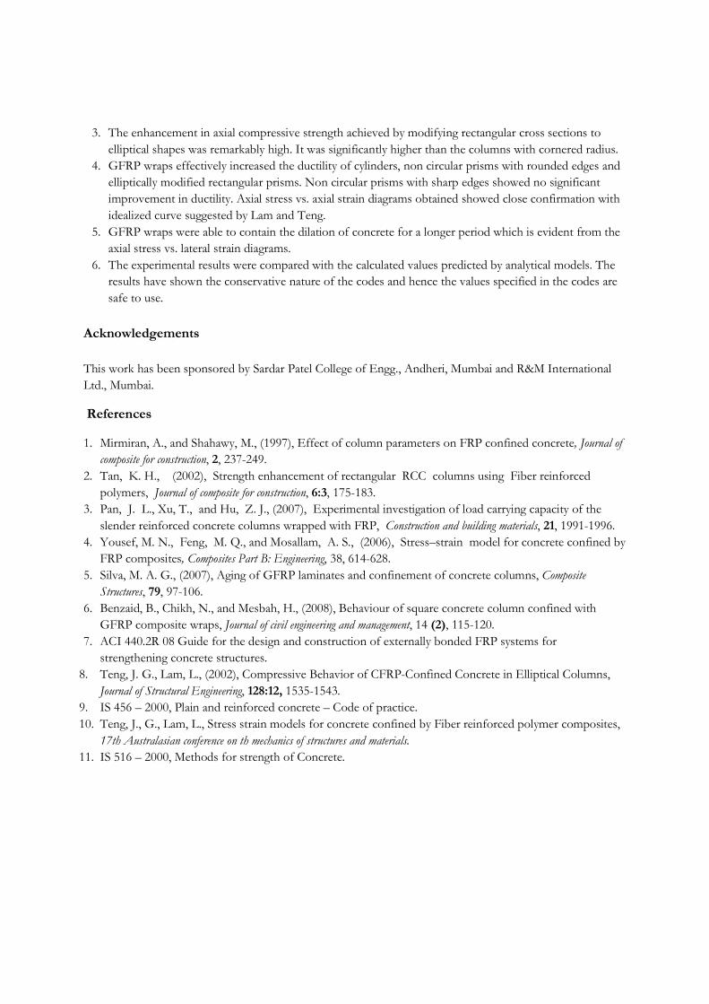
3. The enhancement in axial compressive strength achieved by modifying rectangular cross sections to elliptical shapes was remarkably high. It was significantly higher than the columns with cornered radius.
4. GFRP wraps effectively increased the ductility of cylinders, non circular prisms with rounded edges and elliptically modified rectangular prisms. Non circular prisms with sharp edges showed no significant
improvement in ductility. Axial stress vs. axial strain diagrams obtained showed close confirmation with
idealized curve suggested by Lam and Teng.
5. GFRP wraps were able to contain the dilation of concrete for a longer period which is evident from the axial stress vs. lateral strain diagrams.
6. The experimental results were compared with the calculated values predicted by analytical models. The results have shown the conservative nature of the codes and hence the values specified in the codes are
safe to use.
Acknowledgements
This work has been sponsored by Sardar Patel College of Engg., Andheri, Mumbai and R&M International
Ltd., Mumbai.
References
1. Mirmiran, A., and Shahawy, M., (1997), Effect of column parameters on FRP confined concrete, Journal of
composite for construction, 2, 237-249.
2. Tan, K. H., (2002), Strength enhancement of rectangular RCC columns using Fiber reinforced polymers, Journal of composite for construction, 6:3, 175-183.
3. Pan, J. L., Xu, T., and Hu, Z. J., (2007), Experimental investigation of load carrying capacity of the slender reinforced concrete columns wrapped with FRP, Construction and building materials, 21, 1991-1996.
4. Yousef, M. N., Feng, M. Q., and Mosallam, A. S., (2006), Stress–strain model for concrete confined by FRP composites, Composites Part B: Engineering, 38, 614-628.
5. Silva, M. A. G., (2007), Aging of GFRP laminates and confinement of concrete columns, Composite
Structures, 79, 97-106.
6. Benzaid, B., Chikh, N., and Mesbah, H., (2008), Behaviour of square concrete column confined with GFRP composite wraps, Journal of civil engineering and management, 14 (2), 115-120.
7. ACI 440.2R 08 Guide for the design and construction of externally bonded FRP systems for strengthening concrete structures.
8. Teng, J. G., Lam, L., (2002), Compressive Behavior of CFRP-Confined Concrete in Elliptical Columns,
Journal of Structural Engineering, 128:12, 1535-1543.
9. IS 456 – 2000, Plain and reinforced concrete – Code of practice.
10. Teng, J., G., Lam, L., Stress strain models for concrete confined by Fiber reinforced polymer composites, 17th Australasian conference on th mechanics of structures and materials.
11. IS 516 – 2000, Methods for strength of Concrete.
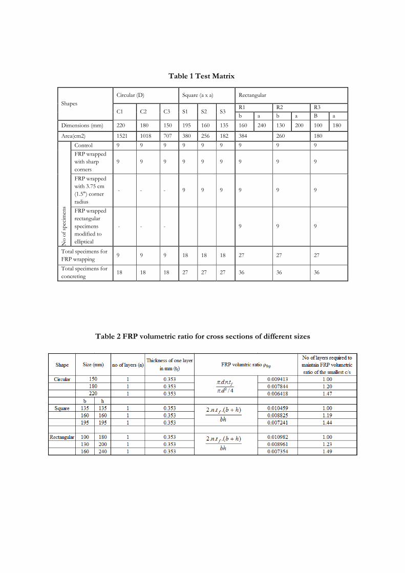
Table 1 Test Matrix
Table 2 FRP volumetric ratio for cross sections of different sizes
Shapes
Circular (D) Square (a x a) Rectangular
C1 C2 C3 S1 S2 S3 R1 R2 R3
b a b a B a
Dimensions (mm) 220 180 150 195 160 135 160 240 130 200 100 180
Area(cm2) 1521 1018 707 380 256 182 384 260 180
No of specimens
Control 9 9 9 9 9 9 9 9 9
FRP wrapped
with sharp
corners
9 9 9 9 9 9 9 9 9
FRP wrapped
with 3.75 cm
(1.5") corner
radius
- - - 9 9 9 9 9 9
FRP wrapped
rectangular
specimens
modified to
elliptical
- - - 9 9 9
Total specimens for
FRP wrapping 9 9 9 18 18 18 27 27 27
Total specimens for
concreting 18 18 18 27 27 27 36 36 36
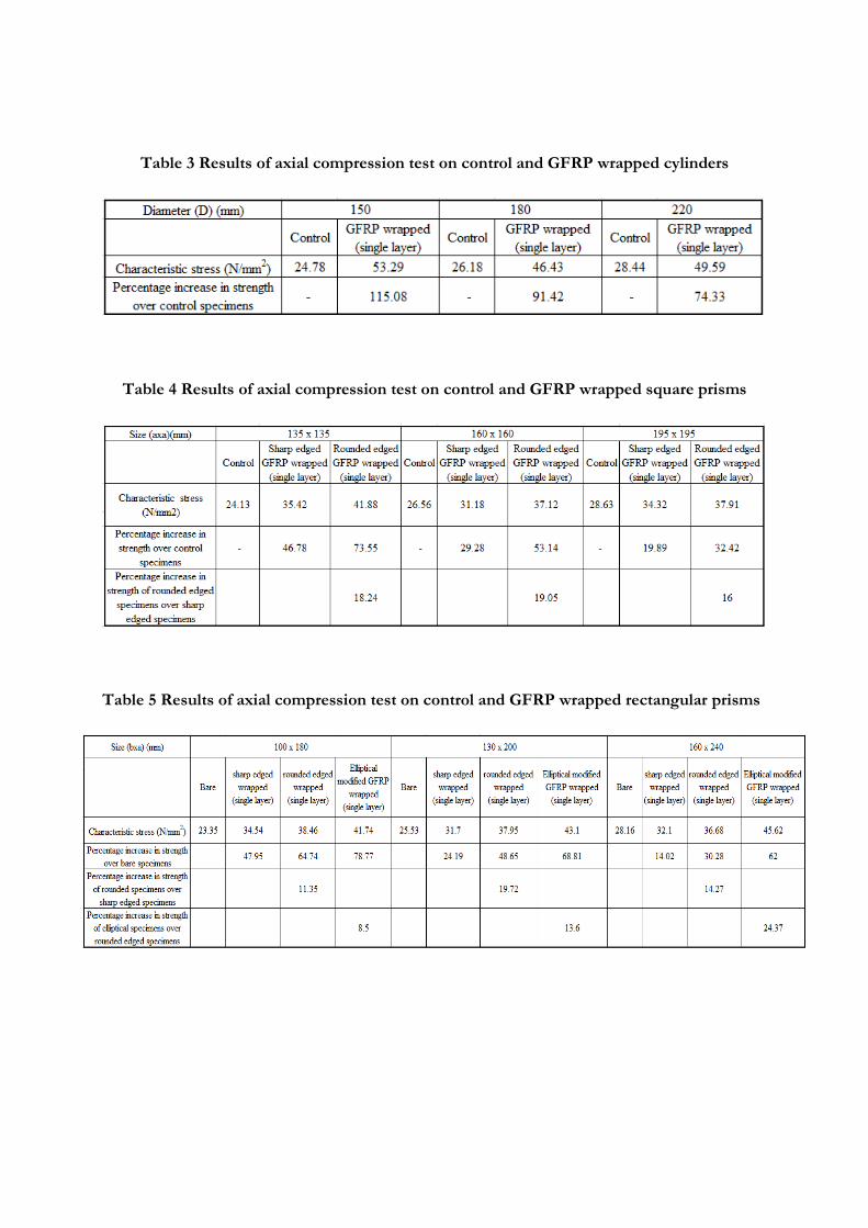
Table 3 Results of axial compression test on control and GFRP wrapped cylinders
Table 4 Results of axial compression test on control and GFRP wrapped square prisms
Table 5 Results of axial compression test on control and GFRP wrapped rectangular prisms
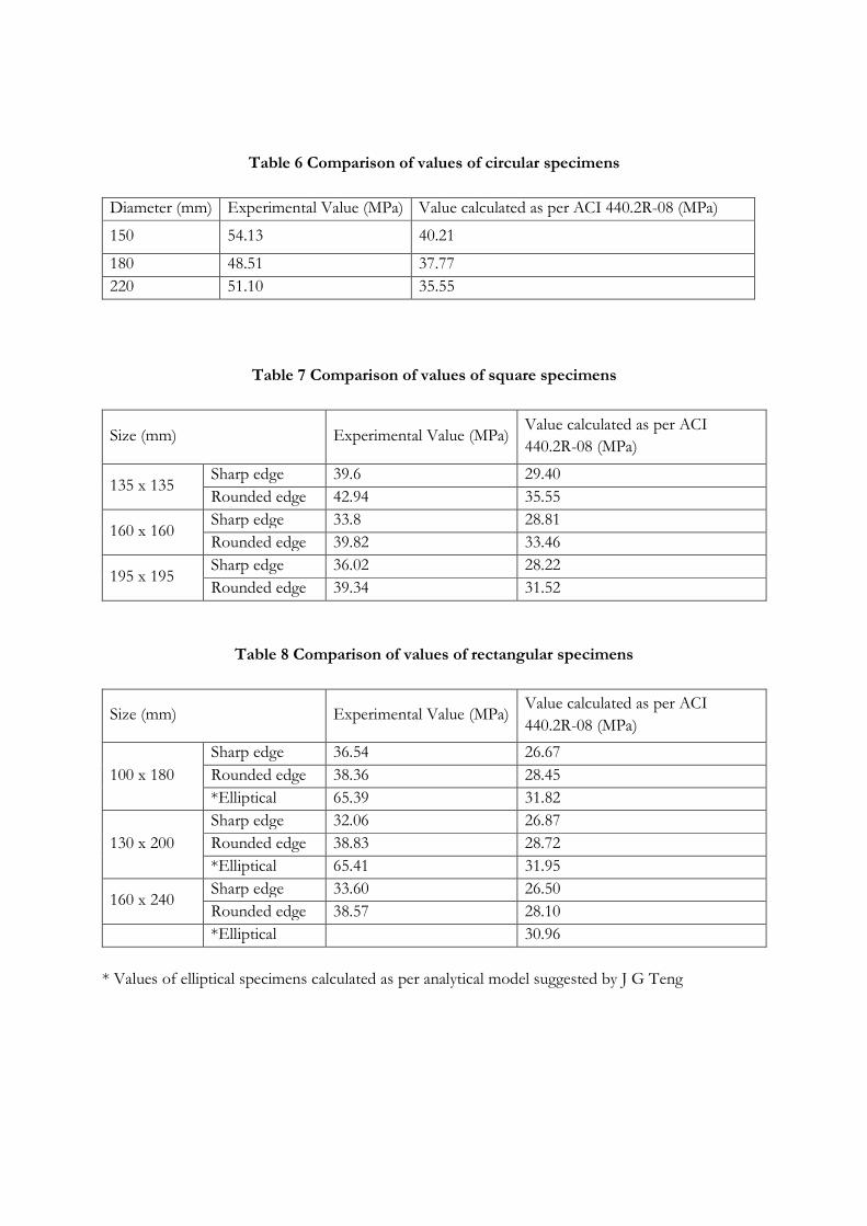
Table 6 Comparison of values of circular specimens
Diameter (mm) Experimental Value (MPa) Value calculated as per ACI 440.2R-08 (MPa)
150 54.13 40.21
180 48.51 37.77
220 51.10 35.55
Table 7 Comparison of values of square specimens
Size (mm) Experimental Value (MPa) Value calculated as per ACI
440.2R-08 (MPa)
135 x 135 Sharp edge 39.6 29.40
Rounded edge 42.94 35.55
160 x 160 Sharp edge 33.8 28.81
Rounded edge 39.82 33.46
195 x 195 Sharp edge 36.02 28.22
Rounded edge 39.34 31.52
Table 8 Comparison of values of rectangular specimens
Size (mm) Experimental Value (MPa) Value calculated as per ACI
440.2R-08 (MPa)
100 x 180
Sharp edge 36.54 26.67
Rounded edge 38.36 28.45
*Elliptical 65.39 31.82
130 x 200
Sharp edge 32.06 26.87
Rounded edge 38.83 28.72
*Elliptical 65.41 31.95
160 x 240 Sharp edge 33.60 26.50
Rounded edge 38.57 28.10
*Elliptical 30.96
* Values of elliptical specimens calculated as per analytical model suggested by J G Teng
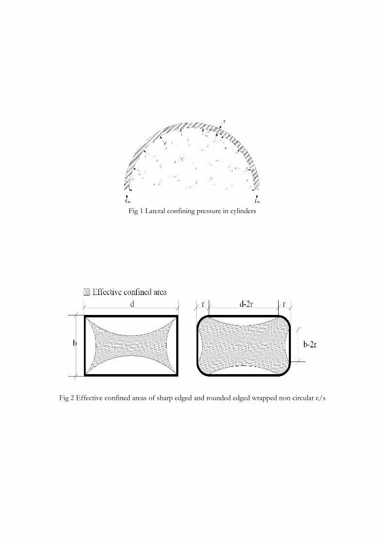
Fig 1 Lateral confining pressure in cylinders
Fig 2 Effective confined areas of sharp edged and rounded edged wrapped non circular c/s
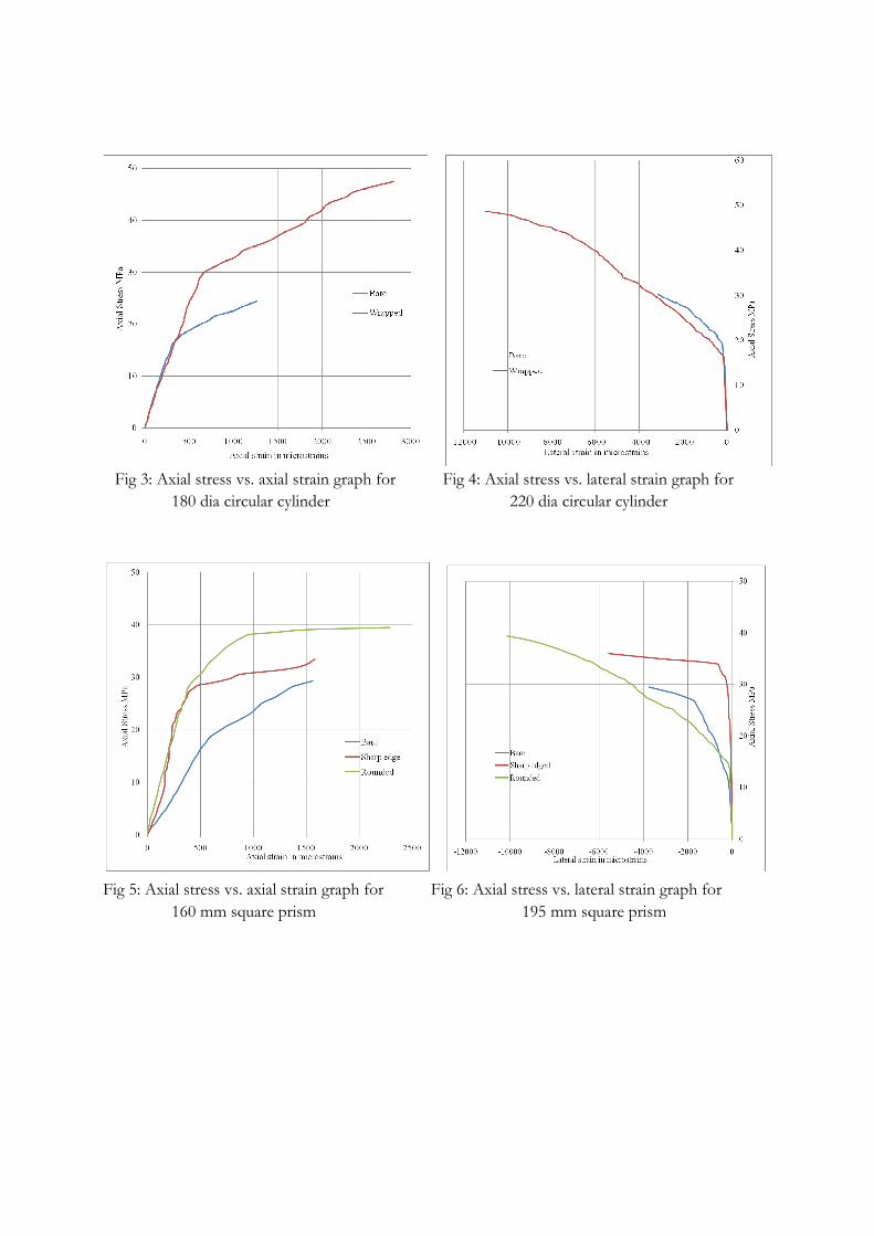
Fig 3: Axial stress vs. axial strain graph for Fig 4: Axial stress vs. lateral strain graph for
180 dia circular cylinder 220 dia circular cylinder
Fig 5: Axial stress vs. axial strain graph for Fig 6: Axial stress vs. lateral strain graph for
160 mm square prism 195 mm square prism
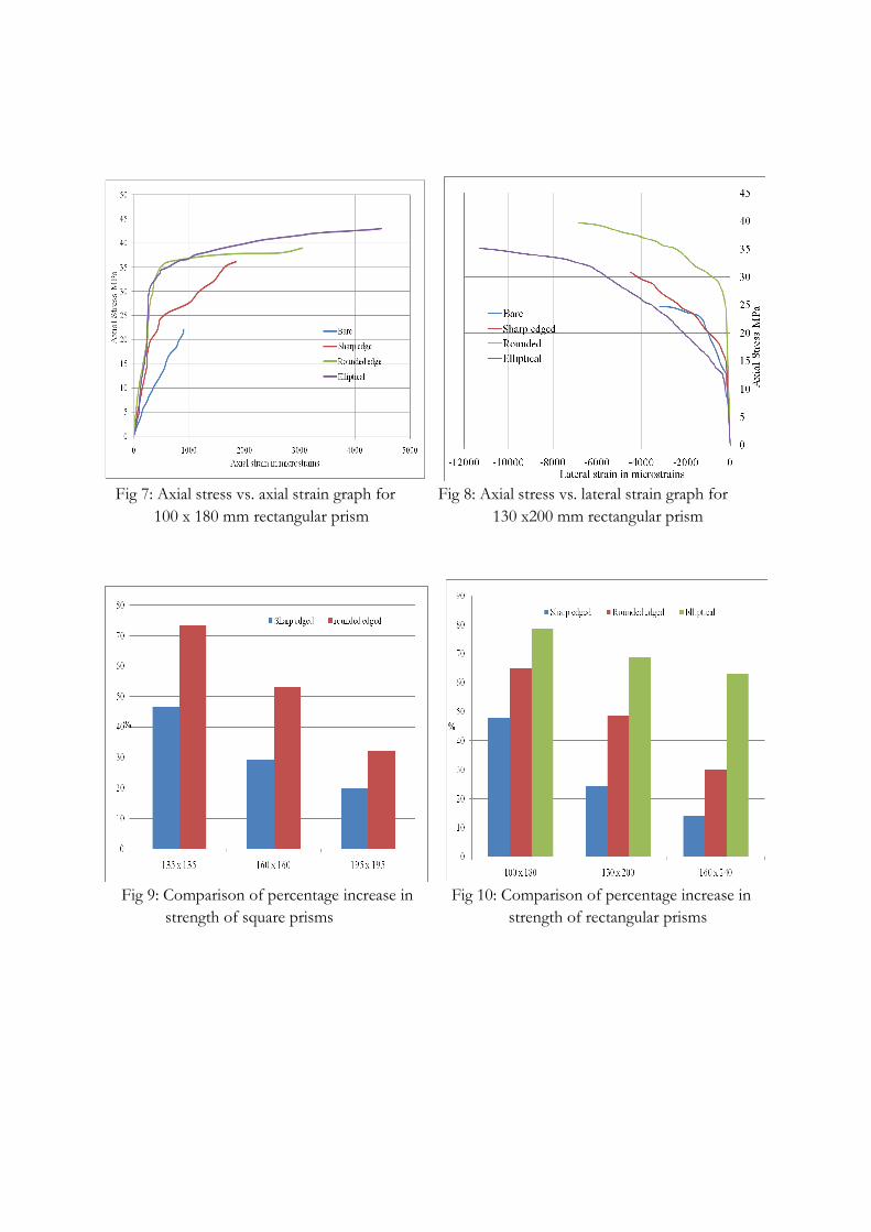
Fig 7: Axial stress vs. axial strain graph for Fig 8: Axial stress vs. lateral strain graph for
100 x 180 mm rectangular prism 130 x200 mm rectangular prism
Fig 9: Comparison of percentage increase in Fig 10: Comparison of percentage increase in
strength of square prisms strength of rectangular prisms
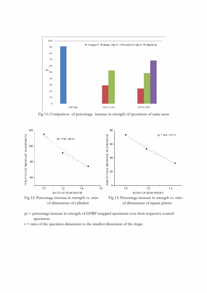
Fig 11: Comparison of percentage increase in strength of specimens of same areas
Fig 12: Percentage increase in strength vs. ratio Fig 13: Percentage increase in strength vs. ratio
of dimensions of cylinders of dimensions of square prisms
pt = percentage increase in strength of GFRP wrapped specimens over their respective control
specimens
t = ratio of the specimen dimension to the smallest dimension of the shape
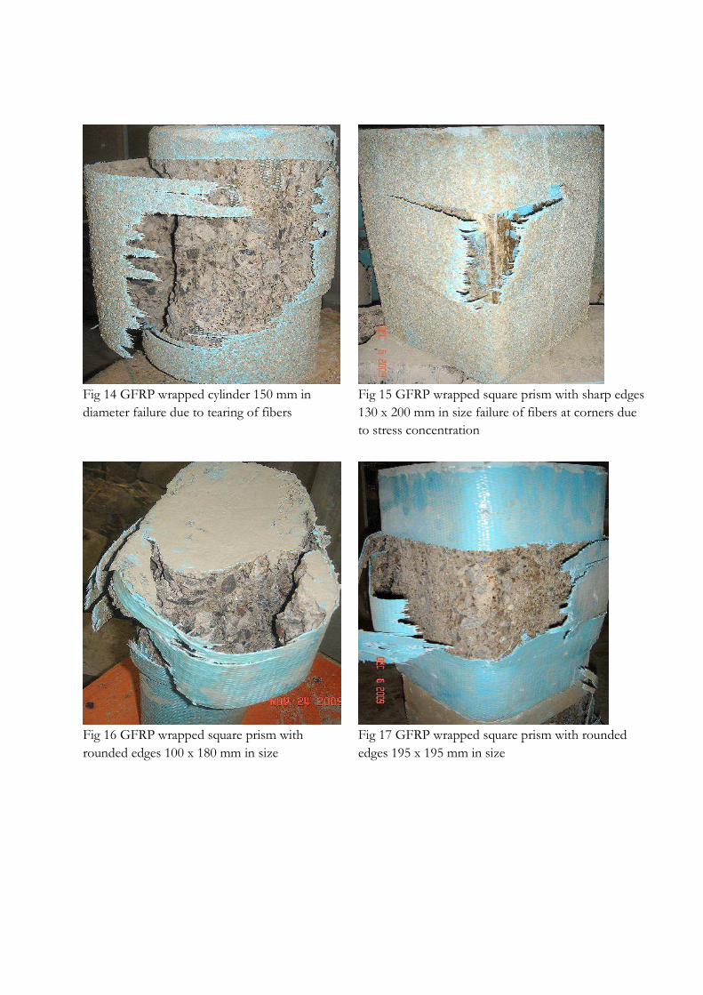
Fig 14 GFRP wrapped cylinder 150 mm in
diameter failure due to tearing of fibers
Fig 15 GFRP wrapped square prism with sharp edges
130 x 200 mm in size failure of fibers at corners due
to stress concentration
Fig 16 GFRP wrapped square prism with
rounded edges 100 x 180 mm in size
Fig 17 GFRP wrapped square prism with rounded
edges 195 x 195 mm in size


![Design of Reinforced Concrete Columns[1]](https://static.fdocuments.net/doc/165x107/55cf881055034664618ceef8/design-of-reinforced-concrete-columns1.jpg)