Effect of Powder Compaction in Plastic Laser Sintering ...edge.rit.edu/edge/P10551/public/SFF/SFF...
13
Effect of Powder Compaction in Plastic Laser Sintering Fabrication Toshiki NIINO and Kazuki SATO Institute of Industrial Science, The University of Tokyo, Japan 4-6-1 Komaba Meguro Tokyo, 153-8505 Japan [email protected] ABSTRACT Powder compaction is introduced into plastic laser sintering fabrication. Compaction was carried out by using a roller of which rotation speed is independently controlled of its traversing speed. This additional process improved packing density of powder bed by a factor of 20% and reduced residual porosity of obtained parts by a factor of 30%. As an advantage, powder compaction can improve mechanical strength of parts of semi-crystalline powder, but increases excessive sinter to reduce fabrication accuracy especially in fabrication of amorphous plastic. This paper presents characteristics of the powder compaction process itself and its effects on performance of obtained parts. INTRODUCTION Laser sintering freeform fabrication (“LS” in the following discription) is a relatively new technology among those processes that produce three dimensional objects from powdery material[1]. Although most of the other powder based production methods include compaction process before sintering, powder in LS is not explicitly compressed. There are many reasons for this difference. Difficulty in adding such function to LS systems due to complexity of mechanism and high temperature in their process chambers to fulfill the laser sintering process are two reasons for the absense of a compacting process. On the other hand, less neccessity of compacting in LS than the other powder sintering processes, in which powder must be compressed by high pressure to form green parts, is another reason. However, the advantage of powder compaction in LS has not yet denied. In this paper, an experimental method that enables powder compaction without adding major change in mechanism to commercially available system is introduced. The method is tested and improvement in density of the powder bed is measured. Porosity and mechanical properties of processed sinters are evaluated. Effect of different powder material characteristics is also discussed; Both of semicrystaline plastic, PA12 (DuraForm ® PA), and amorphous plastic, Polystyrene (CastForm ® PS), are tested, and difference in effect of compaction is discussed.
Transcript of Effect of Powder Compaction in Plastic Laser Sintering ...edge.rit.edu/edge/P10551/public/SFF/SFF...

Effect of Powder Compaction in Plastic Laser Sintering Fabrication
Toshiki NIINO and Kazuki SATO
Institute of Industrial Science, The University of Tokyo, Japan
4-6-1 Komaba Meguro Tokyo, 153-8505 Japan
ABSTRACT
Powder compaction is introduced into plastic laser sintering fabrication. Compaction was
carried out by using a roller of which rotation speed is independently controlled of its
traversing speed. This additional process improved packing density of powder bed by a
factor of 20% and reduced residual porosity of obtained parts by a factor of 30%. As an
advantage, powder compaction can improve mechanical strength of parts of
semi-crystalline powder, but increases excessive sinter to reduce fabrication accuracy
especially in fabrication of amorphous plastic. This paper presents characteristics of the
powder compaction process itself and its effects on performance of obtained parts.
INTRODUCTION
Laser sintering freeform fabrication (“LS” in the following discription) is a relatively new
technology among those processes that produce three dimensional objects from powdery
material[1]. Although most of the other powder based production methods include
compaction process before sintering, powder in LS is not explicitly compressed. There are
many reasons for this difference. Difficulty in adding such function to LS systems due to
complexity of mechanism and high temperature in their process chambers to fulfill the laser
sintering process are two reasons for the absense of a compacting process. On the other
hand, less neccessity of compacting in LS than the other powder sintering processes, in
which powder must be compressed by high pressure to form green parts, is another reason.
However, the advantage of powder compaction in LS has not yet denied. In this paper, an
experimental method that enables powder compaction without adding major change in
mechanism to commercially available system is introduced. The method is tested and
improvement in density of the powder bed is measured. Porosity and mechanical properties
of processed sinters are evaluated. Effect of different powder material characteristics is also
discussed; Both of semicrystaline plastic, PA12 (DuraForm® PA), and amorphous plastic,
Polystyrene (CastForm® PS), are tested, and difference in effect of compaction is discussed.
rosalief
Typewritten Text
Reviewed, accepted September 15, 2009
rosalief
Typewritten Text
193
POWDER COMPACTION
COMPACTION METHOD AND DEFINISIONS
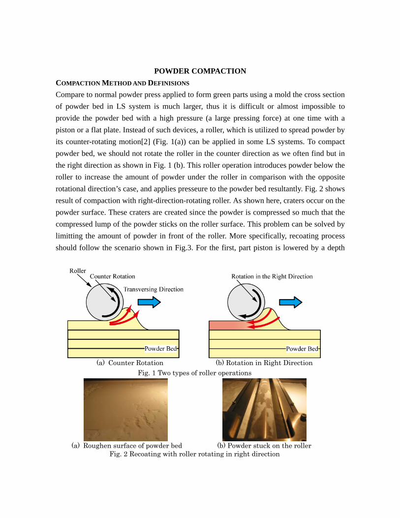
Compare to normal powder press applied to form green parts using a mold the cross section
of powder bed in LS system is much larger, thus it is difficult or almost impossible to
provide the powder bed with a high pressure (a large pressing force) at one time with a
piston or a flat plate. Instead of such devices, a roller, which is utilized to spread powder by
its counter-rotating motion[2] (Fig. 1(a)) can be applied in some LS systems. To compact
powder bed, we should not rotate the roller in the counter direction as we often find but in
the right direction as shown in Fig. 1 (b). This roller operation introduces powder below the
roller to increase the amount of powder under the roller in comparison with the opposite
rotational direction’s case, and applies presseure to the powder bed resultantly. Fig. 2 shows
result of compaction with right-direction-rotating roller. As shown here, craters occur on the
powder surface. These craters are created since the powder is compressed so much that the
compressed lump of the powder sticks on the roller surface. This problem can be solved by
limitting the amount of powder in front of the roller. More specifically, recoating process
should follow the scenario shown in Fig.3. For the first, part piston is lowered by a depth
(a) Counter Rotation (b) Rotation in Right Direction
Fig. 1 Two types of roller operations
(a) Roughen surface of powder bed (b) Powder stuck on the roller
Fig. 2 Recoating with roller rotating in right direction
rosalief
Typewritten Text
194

(supply thickness, ds, in the following description) that is larger than layer thickness, dl.
Then, counter-rotating roller spread the powder and fill the gap created by part piston’s
lowering in the previous procedure. Reversely, the piston is raised up to the level that is
lower than the initial state by the layer thickness. Finally, the roller traverses the powder
bed to compress the powder as rotating in the right direction. Here, we difine “Compaction
Factor,” fc, as
1 ········································ ①
Compaction factor indicates how much the powder bed is compacted, and it becomes zero
when supply depth and layer thickness becomes the same.
PACKING DENSITY OF UNSINTERED POWDER
To evaluate improvement in packing density of powder by the compaction method,
experiments using an LS system were carried out. A hollow box as shown in Fig. 4 is built
and packing density, c, of the unsintered powder (cake in the following description)
remaining in the cavity is calculated by following fomula.
Fig. 3 Compacting Method
rosalief
Typewritten Text
195

········································ ②
where mf, me, Vc and t are mass of the built box including the cake, mass of the emptied
box, volume of the cavity calculated from measurement of its inner dimensions and specific
gravity of the powder material, respectively.
Fig. 5 shows relationship between, packing density and compression factor. In these
Fig. 4 Test specimen for packing density measurement
38
40
42
44
46
48
50
0 0.5 1.0 1.5 2.0
Pac
kin
g D
ensi
ty o
f C
ake
[%]
Compaction Factor
Fig. 5 Relationship between Packing Density and Compaction Factor
Tbl. I Characteristics of PA powder Average grain size 58μm*
Apparent Density (ISO 60) 0.42 g/cm3 (40%)
Tapped Density 0.50 g/cm3 (50%)
Specific gravity 1.00 g/cm3*
*Data provided by 3D systems
rosalief
Typewritten Text
196

experiments, a polyamide powder (DuraForm® PA from 3D Systems) is used. Tbl. I
summarises characteristics of the powder. A prototype version of Semplice (ASPECT Inc.),
which is equipped with a roller system that can control rotation speed and travesing speed
of the roller independently, was employed. Layer thickness of 100m was selected.
Traversing speed, vct, and rim speed, vcr, of the roller during compacting process share the
same value of 100mm/s to avoid friction between the roller and powder bed. Packing
density increased with compaction factor and reached the highest value of 48% when fc =
2.0. This value is larger than in the case that compaction is not applied but still lower than
tapping density of 50%. Higher compaction factor causes failure such as crater and drag of
the part bed.
Fig. 6 shows relationship between packing density and translating speed of the roller in
various compaction factors. The lower roller speed is, the higher packing density becomes.
We can find that the highest density is 49% when vct=50mm/s and fc = 2.0. However, this
compaction condition cannot be used since it causes drag of the previous layer at a certain
provability.
ROTATION SPEED OF ROLLER IN COMPACTION PROCEEDURE
In experiments of the previous section, rotation speed of the roller was controlled so that its
rim speed becomes the same. Following is discussion on phenomena that occur when the
two speed do not match.
38
40
42
44
46
48
50
52
0 50 100 150 200 250
fc =2.0
fc =1.0
Not Applied
Pack
ing
dens
ity [
%]
Translating speed at compacting [mm/s]
Compaction factors
Fig. 6 Relationship between packing density and transverse speed
rosalief
Typewritten Text
197

Fig. 7 includes side views of sinters obtained in various conditions of rotation speed and
traversing speed. Translating speed of 50mm/s was used for photos (b) through (e). Rim
speed was varied. Compaction factor is 2.0 for all photos. The LS system employed in this
research has a pair of feed cylinder on the both sides of its part cylinder. In normal process
without applying compaction process, the both cylinders are used alternately. Contrary,
when compaction process is added, the roller go from one side to the other to spread the
powder, and returns to compact the bed. Thus, only one side of the feed cylinders is used if
we do not switch the spreading and compacting direction intentionally. Since capacity of
a feed cylinder of the employed machine in this research is insufficient to complete one test
piece, the feed cylinder is switched during a build. Bold lines in the pictures in Fig. 7
display layer where the directions were switched, and arrows indicate the compacting
directions. Followings are explanations for results sown in Fig. 7.
(a) fc = 2.0, vct= vcr=100mm/s
Refference for successful build.
(b) fc = 2.0, vct=50mm/s, vcr=25mm/s
Previously built object is dragged in the
forwad direction.
(c) fc = 2.0, vct=50mm/s, vcr=0mm/s
Drag in the same direction is observed but is
milder since not rotating roller does not
introduce so much powder.
(d) fc = 2.0, vct=vcr=50mm/s
Although the rubbing between the roller and
bed is minimized, small drag is still observed.
We cannot find the relation between the
direction of the drag and roller motion. As a
result of compressing large amount of powder
under the roller, pressure rose to very high
level, and a friction force drags the previous
layer in an unpredictable direction.
(e) fc = 2.0, vct=50mm/s, vcr=100mm/s
Since rim speed is faster than traversing speed,
drag in the backward direction occurred.
(a) fc = 2.0, vct= vcr=100mm/s
(b) fc=2.0, vct=50mm/s, vcr=25mm/s
(c) fc=2.0, vct=50mm/s, vcr=0mm/s
(d) fc=2.0, vct=vcr=50mm/s
(e) fc=2.0, vct=50mm/s, vcr=100mm/s
Fig.7 Drags caused in various roller speed conditions
rosalief
Typewritten Text
198

From these results, we obtained the following conclusions.
1. We should equalize the roller’s rim speed with its translating speed to avoid drag.
2. Insufficient and excess speed of the roller results in the drag of the lower layers in front
and back, respectively.
3. High packing density raises the provability of drag even if rim speed is in accordance
with traversing speed.
EFFECT OF POWDER COMPACTION
IMPROVEMENT IN PACKING DENSITY OF SINTER
Fig. 8 shows relationship between packing density and compaction factor at various laser
powers. The packing density was obtained by meausrement of mass and dimensions of test
specimen. Packing density increses with compaction factor unitil fc > 1.0. When fc > 1.0,
the density decreases in turn since amount of excessive sinter became large. The maximum
packing density is 94% while one at the same building condition without compaction is
91%. Though improvement of 3% in packing density seems quite small, relative reduction
rate in porosity of 33% is not a small value.
REDUCTION OF CURL DISTORTION
In this section, we discuss the effect of powder compaction on occurrence of curl distortion.
Cubic specimens with dimensions of 4mm×10mm×80mm were built from PA12
powder. Heat barriers, thin disks which are built below objective sinter for the purporse of
preheating, were not used to obtain measurable distortion. Photos for the specimens built in
the both conditions are shown in Fig. 9. Curl distortions were successfully suppressed, and
the measured value when compacting is applied and not applied are 0.3mm and 0.8mm,
respectively.
We can roughly categorize curl distortion into two groups. The first one includes curls that
are caused during repeating powder supply and laser exposure. We name this type of curls
as “curls in process”. The other one includes those that occur during cooling stage of the
powder bed, after layering is finished. We call this category as “curls in cooling.” Since
curls in cooling occur after objects are build correctly, thickness is constant over all the area
when a flat plate is built as shown in Fig. 10(a). On the other hand, the plate is thinner near
the edge in the case of curls in process as shown in Fig. 10(b), since the curls of the layer
occurred earlier, i.e. lower layer, is larger. In LS process, solidification of melted or
rosalief
Typewritten Text
199

partially melted powder on the objects being solidified previously, repeats in layer by layer
fashion. Since solidification involves shrinkage, LS includes process to generate curl
distortion inherently. To avoid this dilemma, various countermeasures are taken in
commertially available systems and materials. Among these measures, controlling reduce
the curls. LS system’s recent trend toward scalling-up of build-envelope raises difficulty of
precise temperature control over the whole build area. If powder compacting can reduce the
75
80
85
90
95
100
0 0.5 1.0 1.5 2.0
10W15W17W
Pack
ing
Den
sity
[%
]
Compaction Factor
Fig. 8 Relationship between packing density of sinter and compaction factor
a. Top view b. Side view
Fig. 9 Photos of specimens for curl distortion measurement. Top: without compacting, Bottom: with compacting.
a. Curl in cooling (tc te) b. Curl in process (tc > te)
Fig. 10 Two types of curl distortion
tc te
tc te
rosalief
Typewritten Text
200

curl distortion when powder bed temperature is out of the range, application of compacting
is helpful for development of today’s large scaled machines. To evaluate this effect, cubes
with dimension of 52mm×52mm×11.5mm were built at various temperature. The results
are listed in Tbl. II. Tbl. III shows curls of the specimen built at 165C. As shown here,
powder compaction successfully reduced the distortion that was caused by insufficient
powder bed temperature. Though residual curl of 0.2mm when compaction is applied is not
acceptable yet, this can be suppressed by taking other supplementary countermeasures such
as heat barriers. This result demonstrates that powder compaction can expand the width of
the process window from 5K to 10K.
IMPROVEMENT IN MECHANICAL PROPERTIES
Effect of powder compaction on improvement in mechanical properties was investigated.
Tbl. II Building Result in Various Temperature Conditions
Powder bed temperature [C] Result
180 Powder bed melted.
175 Good
170 Good
165 Building is finished, but curl occurred.
160 Collision between roller and sinter. Building was failed
Tbl. III Reduction of curl in building at 165C
Compaction Factor
Cake Density [g/cm3]
Sinter Density [g/cm3]
Height at the center [mm]
Height at the edge
[mm] Curl [mm]
No
Compaction 0.40 0.91 11.3 10.6 0.7
2.0 0.46 0.92 11.5 11.3 0.2
Tbl. IV Improvement in Mechanical Strength
w/o Compaction with compaction increase Rate of increase
Yield Stress [MPa] 42.0 44.0 2.0 5%
Elongation @ break [%] 13.8 14.4 0.6 4%
Flexural stress [MPa] 51.1 56.1 5.0 10%
Flexural Modulus [MPa] 1178 1347 169 14%
Impact strength (not notched) [kJ/m2]
27 36 9 33%
rosalief
Typewritten Text
201

Tensile test (ISO 527), three-point bending test (ISO 178) and Izod impact test (ISO 180)
were performed (Tbl. IV). Impact strength improvement is the most significant, and others
such as bending are following. Performances against tensile stress are also improved, but
the extent of improvement is much smaller. In comparison with a small improvement in
density of 1% the strength is relatively large although a strong relationship between
packing density and mechanical properties of a powder [3]. Here, we can guess that
compressing force during compacting process increased adhesion between grains or layers.
In addition, better improvement in strength against bending than against pulling indicates
that improvement of the adhesion between layers occurred, and it supports our hypothesis
that pressing force is major cause of strength improvement.
COMPACTION OF AMORPHOUS PLASTIC
Although LS process is applicable to all thermoplastics in principle, choices of plastics that
can be used for fabrication of structural parts are quite limited to some semicrystaline
polymers such as polyamide and polypropylene. In this section, we discuss the application
of powder compaction to LS process of amorphous plastic which is mostly used for
fabrication of lost models for casting.
IMPROVEMENT IN PACKING DENSITY OF POWDER
Polystyrene powder (CastForm™ PS, 3D Systems) is used in the following tests. Tbl. V
shows characteristics of the powder compared to polyamide powder discussed in the
previous section. Tbl. VI shows the improvement of density of the powder bed. For
calculation of packing density, specific gravity of 1.05g/cm3 is used as typical value for
polystyrene. A compaction factor of 1.0 can raise the packing density from 39% to 44%
(0.46g/cm3 in density). This value is equivalent to tapped density. Compaction at higher
compaction factor was not successful. These experimental results show that PS powder can
be compacted more easily than PA powder. We can not specify where this difference
derived from; nature of the materials or acquired characteristics when the material is shaped
into powder grains.
IMPROVEMENT IN DENSITY OF SINTER AND EXCESSIVE SINTER
Density of processed sinter is measured. As a test specimen, a cube with dimensions of
52mm×52mm×11.5mm is used. Tbl. VII shows packing density and dimensions of
rosalief
Typewritten Text
202

processed sinters. Compaction of fc = 1.0 improved density of sintered by 3% to 56%. This
packing density is still so low that we cannot use these sinters as structural parts. In
addition, compacting adds excessive sinter reducing accuracy of the parts.
We can conclude that compaction does not bring positive change to process with
amorphous plastic.
DISCUSSIONS
Though, in this research, counter-rotating roller is employed for powder spreading, we can
replace this mechanism with a simple blade and place it just before the compacting roller.
Then, powder spreading and compaction is performed simultaneously in a single roller
traversing action. This will be able to halve the recoating time, consequently.
Compacting phenomena having been discussed in this paper requires elasticity of the
powder or roller mechanism. Otherwise, compaction factor must be equal to increase rate
of powder density. Fig. 11 explains the case that elasticity of powder bed plays dominant
Tbl. V Characteristics of PS powder
PS PA
Average grain size 62μm* 58μm*
Apparent Density 0.40 g/cm3 0.40 g/cm3
Tapped Density 0.46 g/cm3* 0.50 g/cm3
* Data provided by 3D Systems
Tbl. VI Packing Density of PS powder after compaction
Packing Density of Powder
Compaction Factor PS PA
Not applied 39% 41%
1.0 44%(46g/cm3) 44%
2.0 ‐ 46%
Tbl. VII Packing density and dimensions of sinter of PS powder
Compaction Width in x
axis
Width in y
axis
Width in z
axis
Packing
density
Not Applied 51.6mm 51.6mm 11.9mm 53%
fc = 1.0 51.8mm 51.6mm 12.1mm 56%
rosalief
Typewritten Text
203

role in solving the problem. Surface level of powder bed before compacting roller is very
high. When the roller runs over the high powder bed, the powder is once compressed so
that the level is lowered to the bottom line of roller. In this moment, a large amount of
powder exists under the roller, but the stress is relieved by deformation of the powder in the
wide range around the roller. The deformation derives from plasticity and elasticity of the
bed, and deformation owing to the latter one is released and powder level is partially
recovered after the roller passed.
For analysis of compacting powder, we have to establish new analytic model in the future.
Shanjani et al introduced a mathematical model [2], but the model is based on
counter-rotating roller system though we need one for the roller rotating in the reverse
direction. We find similar mechanism in powder rolling process and analytic model is
provided [4, 5]. In this process, powder is compressed to form a seat as it is sandwiched and
conveyed by a pair of rotating rollers. It seems possible to use this model for our
mechanisms. However, modification is still required since phenomenon is slightly different.
For example, thickness of the seat is very much larger in our system. Speeds at which
powder is involved and seat is rolled out are the same.
Quite interesting is that density of the unsintered powder bed is lower than apparent density
when compacting is not performed. This means counter-rotating roller spreads and lays the
powder quite loosely. This is quite adequate to recoating new powder in very thin layer
uniformly without giving drag force to sinters in the previous layers. However, it is not
good for adhesion since adding pressure is an essential prerequisite for adhesion. In that
meaning, adding pressure after forming layer by counter-rotating roller is quite reasonable
for the both of quality of layer and adhesion.
Compaction is quite effective on improvement of adhesion but increases excessive sinter as
its drawback. Since these merits and demerits derive from the same phenomenon, we have
to make some trading-off to use compaction process. It is quite dependent on the
Fig. 11 Schematic view for compaction at high compaction factor
rosalief
Typewritten Text
204

characteristics of material, and in the case of amorphous plastic, we should not apply the
new supplemental process.
CONCLUSION
An experimental compaction method was introduced. The method consists of two processes.
In the first process, a counter-rotating roller spreads the powder, and in the later process, the
part piston is heightened and rotor rotating in the right direction compresses the powder
surface. This compaction process successfully raised powder density of the bed to its
tapped density. To avoid drag of the powder bed, rim speed and traversing speed of the
roller in compaction process should be equalized, and powder bed density should be lower
than tapped density. In case of polyamide, powder compaction reduces the curl distortion
and improves mechanical properties up to 33%. Reduction of curl distortion can double the
width of process window of part bed temperature. Improvement of mechanical property
derives from that in adhesion by adding pressure to the powder. Application of compaction
to amorphous powder increases excessive sinter and we could not find its merit.
REFERENCES
[1] Beaman J, et al, “Solid Freeform Fabrication: A New Direction in Manufacturing,”
1996
[2] Shanjani Y, et al, “Material Spreading and Compaction in Powder-Based Solid Freeform
Fabrication,” Proc. Solid Freeform Fabrication Symposium 2008, pp399-410, 2008
[3] German R, “Powder Metallurgy Science,” Metal Powder Industries Federation, pp
234-252, 1984
[4] Katashinskii V, et al, "Stress-strain state of powder being rolled in the densification
zone, II. Distribution of density, longitudinal strain, and contact stress in the
densification zone," Powder Metallurgy and Metal Ceramics, vol. 12(252), pp. 9-13,
1983
rosalief
Typewritten Text
205