Impact of ABO mismatching on the outcomes of allogeneic BMT: IPD based meta-analysis

Lappeenrannan teknillinen yliopisto Lappeenranta University of Technology Xiaoyan Li Effect of Mechanical and Geometric Mismatching on Fatigue and Damage of Welded Joints
Thesis for the degree of Doctor of Science (Technology) to be presented with due permission for public examination and criticism in the auditorium 1382 at Lappeenranta University of Technology, Lappeenranta, Finland on the 18th of December, 2003, at noon.
Acta Universitatis Lappeenrantaensis 168

-ii-
ISBN 951-764-829-4 ISSN 1456-4491
Lappeenranta teknillinen yliopisto
Digipaino 2003

-iii-
Abstract Xiaoyan Li Effect of Mechanical and Geometric Mismatching on Fatigue and Damage of Welded Joints Lappeenranta, 2003 75 p. + Appendices 117 p. Acta Universitatis Lappeenrantaensis 168 Diss. Lappeenranta University of Technology ISBN 951-764-829-4 ISSN 1456-4491 The future of high technology welded constructions will be characterised by higher strength materials and improved weld quality with respect to fatigue resistance. The expected implementation of high quality high strength steel welds will require that more attention be given to the issues of crack initiation and mechanical mismatching. Experiments and finite element analyses were performed within the framework of continuum damage mechanics to investigate the effect of mismatching of welded joints on void nucleation and coalescence during monotonic loading. It was found that the damage of under-matched joints mainly occurred in the sandwich layer and the damage resistance of the joints decreases with the decrease of the sandwich layer width. The damage of over-matched joints mainly occurred in the base metal adjacent to the sandwich layer and the damage resistance of the joints increases with the decrease of the sandwich layer width. The mechanisms of the initiation of the micro voids/cracks were found to be cracking of the inclusions or the embrittled second phase, and the debonding of the inclusions from the matrix. Experimental fatigue crack growth rate testing showed that the fatigue life of under-matched central crack panel specimens is longer than that of over-matched and even-matched specimens. Further investigation by the elastic-plastic finite element analysis indicated that fatigue crack closure, which originated from the inhomogeneous yielding adjacent to the crack tip, played an important role in the fatigue crack propagation. The applicability of the J integral concept to the mismatched specimens with crack extension under cyclic loading was assessed. The concept of fatigue class used by the International Institute of Welding was introduced in the parametric numerical analysis of several welded joints. The effect of weld geometry and load condition on fatigue strength of ferrite-pearlite steel joints was systematically evaluated based on linear elastic fracture mechanics. Joint types included lap joints, angle joints and butt joints. Various combinations of the tensile and bending loads were considered during the evaluation with the emphasis focused on the existence of both root and toe cracks. For a lap joint with a small lack-of-penetration, a reasonably large weld leg and smaller flank angle were recommended for engineering practice in order to achieve higher fatigue strength. It was found that the fatigue strength of the angle joint depended strongly on the location and orientation of the pre-existing crack-like welding defects, even if the joint was welded with full penetration. It is commonly believed that the double sided butt welds can have significantly higher fatigue strength than that of a single sided welds, but fatigue crack initiation and propagation can originate from the weld root if the welding procedure results in a partial penetration. It is clearly shown that the fatigue strength of the butt joint could be improved remarkably by ensuring full penetration. Nevertheless, increasing the fatigue strength of a butt joint by increasing the size of the weld is an uneconomical alternative. Keywords: Welded Joints, LEFM, Mismatching, Fatigue, FEM UDC 624.078.45 : 539.422.24

-iv-

-v-
Preface The research work reported in this thesis was partially carried out within the Laboratory of Steel Structures, Department of Mechanical Engineering, Lappeenranta University of Technology within the project “The Fatigue Strength of Thick Walled Structure, X-FAT” funded jointly by Metso Paper Inc., Andritz-Ahlstrom, KCI Konecranes, Timberjack, Rautaruukki, VR, BMH Wood Technology, VTT Manufacturing Technology and the Finnish National Technology Agency (TEKES). Other portions of the research work were carried out in China with the partial financial support of the Beijing Natural Science Foundation under the grant number 2972007. I would like to express my gratitude to Professor Gary Marquis who served as the supervisor of this thesis. His encouragement and guidance helped bring this thesis to its final completion. I would also like to thank Dr. Teuvo Partanen and Emeritus Professor Erkki Niemi for their encouragement during the early stages of this work. Prof. Wolfgang Fricke from TUHH, Germany and Dr. Timo P.J. Mikkola from PI-Rauma, as pre-reviewers of the thesis, provided numerous valuable comments that helped produce a more clear manuscript. Several of the appended papers were co-authored by Dr. Timo Nykänen and Mr. Timo Björk. Mr. Björk served as project manager for the project X-Fat project, Dr. Nykänen assisted with numerous technical issues and performed similar analysis of several alternate joint geometries. I am indebted due to their help and support. My gratitude is due to professor Xitang Tian and professor Hongguan Zhu from Harbin Institute of Technology for their guidance on a part of the research regarding the mismatching effect of welded joints. I am also indebted to Mr. Q. Hao, my former MSc student, for his assistance during the experimental and finite element analysis of damage behaviour of welded joints. Professor Y. W. Shi and professor Y.P. Lei from Beijing University of Technology are acknowledged for their valuable discussions during damage research. Special thanks are given to Professor Arto Verho and the Lappeenranta University of Technology Foundation and the Beijing University of Technology for either of their partial financial support and the opportunity they offered leading to the completion of this thesis. Finally, I wish to acknowledge the continuous support, patience, understanding and encouragement of my wife Xiaoyan Zhang (PhD, MD) and my son PengPeng during the different stages of this thesis, their sacrifice was immense - my gratitude is profound.
Xiaoyan Li Lappeenranta, November, 2003

-vi-

-vii-
CONTENTS Abstract ……………………………………………………………………...…………………… iii Preface ……………………………………………………………………..…………………… v Contents ………………………………………………………………………..………………… vii Nomenclature …………………………………………………………………………………… ix Original Features ………………………………………………………………….……………… xi Dissertation ………………………………………………………………………………………xiii 1 Introduction ……………………………………………………………………….…………… 1
1.1 Objectives…………………………………………………………………..…………… 2 1.2 Research Methods and Outline of the Work………………………………...………..… 2
1.2.1 Aspects of Geometrical Discontinuities and Mechanical Mismatching of Welded Joints … 2 1.2.2 Crack Initiation in Welded Joints …………….………………………..…………..… 3 1.2.3 Fatigue Crack Growth and Characterization ………………..……………………...… 3
1.2.3.1 Linear Elastic Fracture Mechanics (LEFM) Approach ………………………….. 3 1.2.3.2 Elastic-Plastic Fracture Mechanics (EPFM) Approach ………………………….. 4
2 Geometrical Discontinuity and Mechanical Mismatching ………………………………….… 8 2.1 Geometrical Discontinuity Dependency of Welded Joints ……………………….…… 8 2.2 Mismatching of Welded Joints …………………………………………………………10
2.2.1 Matching and Mismatching Concepts …………………………………….…………11 2.2.1.1 Changes of Hardness Distribution ………………………………..………………11 2.2.1.2 Tensile Strength Variation ………………………………………..…………… 12
2.2.2 Mismatching Effects ……………………………………………….……….……… 12 2.3 Summary ………………………………………………………………………….……19
3 Experimental Approach to Damage and Fatigue of Welded Joints …………………….…… 20 3.1 Idealization of Welded Joints ………………………………………………………… 20 3.2 Damage Behaviour of Mismatched Welded Joints …………………………………… 22 3.3 Fatigue Behaviour of Mismatched Welded Joints …………………………….….…… 27
3.3.1 The Effect of Mechanical Mismatching on Fatigue Crack Propagation ….………… 27 3.3.2 The Effect of Mechanical Mismatching on Fatigue Crack Closure ……….……… 28
3.4 Summary……………………………………………………………………….……… 31 4 FEM Solutions Fatigue Crack Growth and Damage …………………………...….………… 32
4.1 Damage of Welded Specimen based on CDM …………………………….………… 32 4.2 Influence of Geometrical Discontinuity and Load Condition on Fatigue Strength of Welded Joints . 37
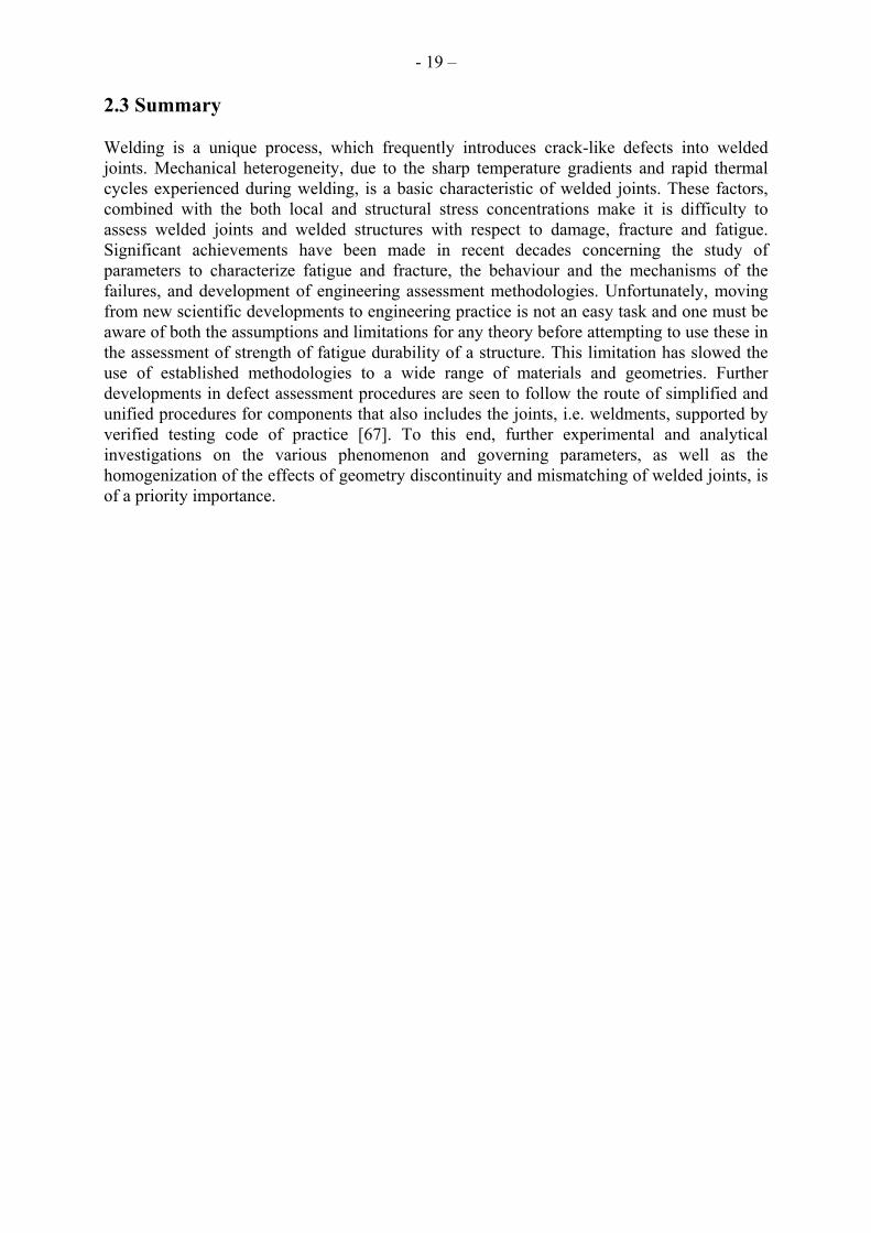
4.2.1 Lap Joint ………………………………………………………….……….………… 41 4.2.2 Angle Joint …………………………………………………………………..……… 43 4.2.3 Butt Joint ……………………………………………………………………………. 48
4.3 Fatigue Crack Tip Fields Elastic-Plastic Fracture Mechanics (EPFM) Approach …… 50 4.3.1 Progressive Crack-tip Fields of Mismatched Specimens ………………………………… 50 4.3.2 Applications of the J-Integral to the Fatigue Crack Growth of Mismatched Welds ….. 51
4.4 Summary ……………………………………………………………………………… 52 5 Conclusions ……………………………………………………………………..…………… 53 Summary of Appended Papers…………………………………………………………………… 54 References …………………………………………………………..…………………………… 56 Appendix A - Published Papers Appendix B - Analysis of Fatigue Crack Growth in Welded Joints by EPFM Approach

-viii-

-ix-
Nomenclature a crack length
0a , ia initial crack length c material’s constant E Young’s Modulus
tE slope of the uniaxial true stress-natural strain curve at the current stress level Mσ f current void volume fraction
cf critical void fraction
Ff modified void volume at failure
uf original ultimate value of void volume fraction
Nf volume fraction of void forming particle f& differentiation of void volume fraction
failuref& differentiation of void volume fraction due to the influence of material failure
growthf& differentiation of void volume fraction due to the increment of existing voids
nucleationf& differentiation of void volume fraction due to the increment of nucleation of new voids Hv Vickers hardness J Rice’s contour integral K stress intensity factor
K∆ range of stress intensity factor cK material constant
m material’s constant N number of fatigue cycle
charN characteristic fatigue life
meanN mean fatigue life
refN reference fatigue life
1 2 3, ,q q q extra parameters for modified Gurson’s model S standard deviation
ijs stress deviator W strain energy density Y fracture mechanics geometry factor δ
p elongation
mε effective plastic strain
nε mean strain for void nucleation ( ) p
kkε& plastic part of the macroscopic strain increment ε∆ strain range of a cycle
ϕ area reduction Φ Gurson’s yield function for axially symmetric deformation ν Poisson’s ratio
ijσ average macroscopic Cauchy stress tensor
Mσ equivalent tensile flow stress representing the actual microscopic stress-state in the matrix material

-x-
eqσ macroscopic effective von Mises stress
sσ uniaxial yield stress
bσ ultimate stress σ∆ stress range of a cycle

-xi-
Original Features Work in this thesis has been focused on the geometrical discontinuities, root side cracking, mechanical mismatching, and the damage and fatigue behaviour of welded joints. Both experimental and finite element analysis methods have been employed. The problems considered are relevant to future generations of fabricated structures that are expected to employ higher grades of steel and have higher fatigue strength requirements. The formation and growth of micro-voids and micro-crack initiation and growth mechanisms were explored from the materials point of view in terms of continuum damage mechanics. Extensive finite element analysis and linear elastic fracture mechanics has been used to parametrically evaluate several joint types with respect to fatigue. The following features are believed to be original: (1) The effect of critical geometric parameters and loading conditions on fatigue strength were
considered for three commonly used joint types. The joint geometries were the lap joint, angle joint and butt joint. These were only three of the joints considered within a larger research effort leading to the development of a practical engineering tool for the assessment of thick walled structures where full penetration cannot always be assured. Fracture mechanical based numerical studies on hundreds of models were conducted in this effort. Reasonable weld geometry parameters were suggested.
(2) Damage of welded joints was investigated by experimental and numerical methods. The damage
mechanisms were demonstrated and the critical damage location of the joints was predicted and the damage resistance was evaluated.
(3) Fatigue crack growth in idealized welded joint models was studied both by experimental and
finite element methods. The effect of mechanical mismatching on fatigue crack growth rate and fatigue was interpreted by its effect on fatigue crack closure.
(4) The applicability of elastic-plastic fracture mechanics as a parameter to characterize low cycle
fatigue in welded joints was assessed. This included both CTOD and the J-integral.

-xii-

-xiii-
Dissertation This dissertation consists of two major parts. Part one provides the background of the research, the methodologies employed in the investigation and discussions of the most significant findings. In part two, seven international publications are appended. The author of this thesis was the principal scientific investigator and the main author for six of these. The author’s contribution to appended article 5 is related to his analysis of the lap, angle and butt joints discussed in this paper. 1. X. Y. Li, Q. Hao, Y. W. Shi, Y. P. Lei and G. Marquis, Influence of Mechanical Mismatching
on the Failure of Welded Joints by Void Nucleation and Coalescence, International Journal of Pressure Vessels and Piping, 80(2003), pp.647-654
2. X. Y. Li, T. Partanen, T. Nykänen and T. Björk, Finite Element Analysis of the Effect of
Weld Geometry and Load Condition on Fatigue Strength of Lap Joint, International Journal of Pressure Vessels and Piping, 78(2001), pp.591-597
3. X. Y. Li, T. Partanen, T. Nykänen and T. Björk, Evaluation of Fatigue Strength of Angle Joint
with Fully Penetration, Proceedings of the 7th International Symposium of Japan Welding Society in the Theme “Today and Tomorrow in Science and Technology of welding and Joining”, 20-22 November, 2001, Kobe, Japan, Vol.2, Editor T. Ohji, pp.1225-1230
4. X. Y. Li, T. Nykänen, T. Björk and G. Marquis, Fracture Mechanics Analysis of Partial
Penetrated Butt Welds, Design and Analysis of Welded High Strength Steel Structures, Editor J. Samuelsson, Papers Presended at a Meeting Organized in Conjunction with the Eighth International Fatigue Congress, Fatigue 2020, Held in Stockholm, Sweden, 3-7 June, 2002, pp.139-149
5. T. Nykänen, X. Y. Li, T. Björk and G. Marquis, A parametric fracture mechanics analysis of
welded joints in as welded condition, (submitted to Engng. Fract. Mech.) 6. Li Xiaoyan, Zhu Hongguan and Tian Xitang; A Study of Fatigue Crack Growth and Crack
Closure in Mechanical Heterogeneous Welded Joints, Engineering Fracture Mechanics, Vol.55, No.4, 1996, pp.689-697
7. X. Y. Li, X.T. Tian and H. G. Zhu, Fatigue Crack Growth and Crack Closure of Simulated
Over-Matched Welded Joints, ACTA Metallurgica Sinica (English Letters), Vol.13, No.1, 2000, pp.117-122

-xiv-

- 1 -
1 Introduction Weldments and welded joints are used in a variety of safety critical structures, including buildings, ship and offshore structures, machinery, power plants, automobiles and airframes etc. Very often, welds are the only practical means for joining massive structures which themselves can be subject to adverse loading conditions. Weldments and welded joints are often the objects of intense scrutiny when structural weight is considered or when fatigue or fracture problems. The study of damage and fatigue in welded joints is, therefore, of great relevance when assessing the durability and damage tolerance of a structure. Fatigue failures remain a depressingly common occurrence despite more than a century of research effort since the first fatigue failure in railway axles was reported [1]. This is partially the result of engineers continuing to strive for using new materials and to “push the limit” for load carrying structures. Many cyclic loaded structures and components are now fabricated by welding. Past experience, however, has shown that a high proportion of fatigue failures are associated with welds [2-4]. Fortunately, the importance of designing welded structures against fatigue failure has been recognized for some time, and current standards and codes of practice include fatigue design rules for welded joints [5-10]. Despite the continuing occurrence of fatigue failures, there does not seem to be any evidence of an inadequacy in current design rules. In some failure cases, the possibility of fatigue fracture was never considered, although the incidence of this category of oversight is steadily decreasing. In other failures, fatigue design was not carried out sufficiently thoroughly, the main deficiencies being the incorrect estimate of the structural loading, inadequate stress analysis with respect to fatigue, unexpected cyclic loading, and the presence of significant weld flaws arising from poor welding and inspections practices. Unfortunately, many engineers also do not have an appreciation for the effect of welding variations and geometry changes on fatigue. If weld geometry or the welding processes are changed during fabrication, the fatigue strength of a component may be completely unknown. Fatigue failure usually includes two stages: crack initiation and crack propagation. Studies in the recent decades have shown that the initiation and propagation of cracks from welded joints is different from that in homogeneous base materials due to the high level of residual stresses, strength mismatching, complex microstructure, etc., found in welds [11-21]. For longer life fatigue, the failure process can be considered as stress controlled dominated by crack propagation. For shorter life fatigue, however, the failure is frequently found to be a strain controlled process, such as low cycle fatigue (LCF), and crack initiation is usually modelled. In engineering practice, fusion welding is widely used during the fabrication of complex structures. The production of fusion welds is similar in many respects to metal-producing operations. The composition limits that must be met by the weld metal are as equally restrictive as those applied to regular cast and wrought products. Welding processes are unique, however, because of the unusual conditions applied to welds result in highly localized hardening treatment. Extremely rapid thermal changes often take place. These unusual conditions result in localized expansion and contraction, chemical reactions between the metal and the ambient atmosphere, abrupt microstructural changes and alterations in mechanical and physical properties.

- 2 -
1. 1 Objectives If past trends hold true, increased strength demands will be placed on welds in future generations of structures. There is clearly a trend in many industries toward the use of higher strength materials, which will place more demand on the geometry control of welded connection and on the mechanical strength mismatching of the joint. Some priority issues that will comprise topics for future research on welded joints includes:
- The influence of geometrical discontinuities combined with crack-like welding imperfections on fatigue strengths,
- Better understanding of the important role of the weld joint geometry, including lack of full penetration, on fatigue strength,
- Identifying the site of potential crack initiation for smooth and defect free welded joints, - Better understanding of the influences of mechanical mismatching on fatigue for current and
new generations of materials in order to correctly specify the correct matching for fabrication,
- Identifying the applicable parameters governing the initiation and propagation of fatigue crack in welded joints with mechanical mismatching, and
- Clarifying the mechanisms that cause the distinct behaviour of welded joints as compared to homogeneous materials with respect to fatigue.
With the above issues in the mind, the research effort leading to this thesis has focused on investigating and understanding the effect of geometrical discontinuities on fatigue strength. This included extensive numerical parametric studies of several typical joint types. Especially considered were, e.g., plate thickness of the members to be joined, the dimensions of the welds and the pre-existence of cracks including both toe defects and lack of full penetration. The effect of mechanical mismatching of welded joints on the behaviour of micro crack initiation was also investigated within the framework of continuum damage mechanics (CDM) and elastic plastic crack propagation. The effects of different mechanical and geometric parameters on fatigue fracture of a welded joint using linear elastic fracture mechanics was studied. These investigations provide the information needed to make practical evaluation of fatigue crack phenomenon in defect free welded joints and welded joint with pre-existing cracks or crack-like imperfections. 1. 2 Research Methods and Outline of the Work Both numerical and experimental methods were used to study both crack initiation and propagation in welded joints. These methods have been employed by a number of researchers in the past decades with great success. The methods are, therefore, well established and well suited for the new issues addressed in these studies. Throughout this thesis, relatively simple load conditions have been used both in the experiments and in the numerical simulations. Variable amplitude or other types of complex loading are not considered. 1. 2.1 Aspects of Geometrical Discontinuities and Mechanical Mismatching of Welded Joints Since it is believed that the geometrical discontinuities and mechanical mismatching have importance influence on fatigue behaviour of welded joint, the systematic study of geometrical discontinuities and mechanical mismatching is a precondition for understanding of the unique behaviour and mechanisms of crack initiation and growth in welded joints.

- 3 -
During the welding process, different portions of the joint undergo different thermal cycles that produce a variety of microstructures and mechanical properties. The changed microstructures of a welded joint, from weld to base metal, are classified as 1) weld solidified cast-like structure zone, 2) solid-liquid transition structure zone, 3) coarse grain zone, 4) recrystallized zone, 5) partial transformed zone, 6) tempered zone and 7) unaffected base metal respectively [22]. The variation in mechanical properties from one zone to the next results in significant mechanical mismatching or mechanical heterogeneity that becomes critical in understanding high quality welded joints. Following a literature review, the geometrical discontinuity and mechanical mismatching of welded joints is summarized in Chapter 2. Geometrical discontinuity dependency, mismatching effects of welded joints, concerning the fatigue strength evaluation and fatigue crack propagation behaviour, were presented. 1.2.2 Crack Initiation in Welded Joints Evidence suggests that the fatigue crack initiation behaviour of high quality, smooth and essentially defect free welded structures is strongly influenced by mechanical mismatching. A scanning electrical microscope (SEM) with a dynamic loading system was the primary experimental tool for making direct observations of the initiation, cohesion and growth of micro voids and micro cracks. Emphasis was focused on the influence of mechanical mismatching on the behaviour of initiation and cohesion of the micro voids and micro cracks. This is described in Chapter 3. A numerical study of crack initiation is included in Chapter 4. Gurson [23,24] was the first to suggest that the scalar parameter, micro void volume fraction, could be used for the description of the nucleation and growth of micro voids in ductile materials. The modified Gurson’s model, suggested by Tvergard and Needleman [25-27] with respect to the behaviour of small void volume fractions and for void coalescence has been adopted in this thesis and is implemented with the finite element approach in Chapter 4 to simulate the damage evolution in welded joints during monotonic loading. 1.2.3 Fatigue Crack Growth and Characterization 1.2.3.1 Linear Elastic Fracture Mechanics (LEFM) Approach In view of its importance of the structural integrity of welds, fatigue crack growth has received considerable attention [3,28]. The LEFM approach provides a particularly convenient means of correlating fatigue crack growth rate data because the stress conditions at the crack tip can be described by a single parameter, the stress intensity factor. Many attempts have been made to describe the fatigue crack growth rate curve, usually semi or wholly empirical. For a wide range of mode I crack growth rates, data are conveniently represented by the Paris-Erdogan equation [29], which is commonly encountered in the literature and is widely used to assess fatigue crack propagation. Paris’s power law is also recommended by IIW for the calculation of fatigue class of welded joint and components [9]. The fatigue classes of several welded joints, including butt joint, angle joint and lap joint, were calculated based on IIW recommendation and the methodology was presented in Chapter 4. The above results are a part of the project X-FAT whose aim was to provide a practical methodology for design engineers when choosing the thickness of the plates to be joined, the dimensions of the welds, the load conditions and the relevant degree of penetration. The possibility of both root cracks and toe cracks were studied parametrically.

- 4 -
The X-FAT project included a large group of welded joints that were of interest to Finnish industrial companies designing thick walled structures. The joints considered are shown in Figure 1.1. Work done during this thesis contributed partially to an extensive database and a related software package. The front page of the software X-FAT is shown in Figure 1.2. 1.2.3.2 Elastic-plastic Fracture Mechanics (EPFM) Approach Basic principles adopted in IIW recommendations for the determination of the driving force of a fatigue crack, the stress intensity factor range, are only based on the consideration of structural discontinuities such as the section changes near the joint, possible misalignment and the profile of weld, etc. A more complete solution of fatigue crack growth in welded joints and components depends not only on the mechanical properties of the material at crack tip, but also on the mechanical properties of adjacent area. In the low cycle fatigue regime it is known that the fatigue life of joints with similar geometries and weld profiles can show big differences in strength if the welding process parameters or filler metal are changed. Additionally, in case of low cycle fatigue when yielding and crack tip plasticity are involved, the concept of linear fracture mechanics is no longer valid for characterizing fatigue crack growth. LEFM cannot be adopted unless the region of plasticity surrounding the crack tip is small in comparison with both crack length and the remaining ligament of the uncracked material [30]. Accordingly, elasto-plastic fracture mechanics (EPFM) approach should be adopted in charactering fatigue crack growth in cases the yielding and crack-tip plasticity are concerned. In Chapter 4, this thesis presented the challenges that might be faced in applying conventional concepts, such as the J integral, COD/CTOD, and crack closure in the evaluation of fatigue crack growth of welded joint [31-52]. A detailed explanation for applying of the J integral concept in welded joints, both under monotonic and cyclic load conditions, is presented in appendix B.

- 5 -
Fig.1.1 Thick wall welded joints involved in X-FAT

- 6 -
3A
3E
3D
3C
3B
Fig.1.1 Thick wall welded joints involved in X-FAT (cont.)

- 7 -
Fig. 1.2 Initial user interface screen for the X-FAT program.
- 8 –
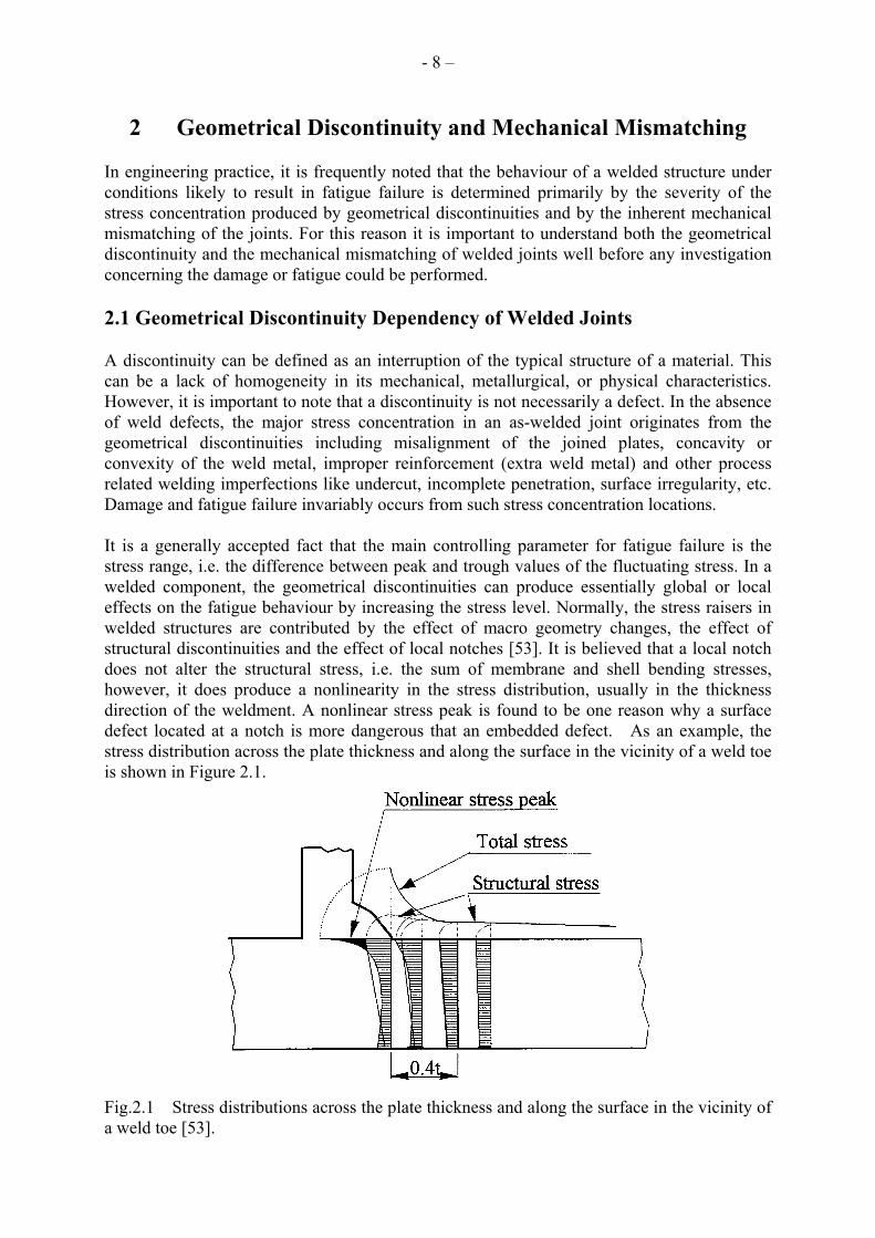
2 Geometrical Discontinuity and Mechanical Mismatching In engineering practice, it is frequently noted that the behaviour of a welded structure under conditions likely to result in fatigue failure is determined primarily by the severity of the stress concentration produced by geometrical discontinuities and by the inherent mechanical mismatching of the joints. For this reason it is important to understand both the geometrical discontinuity and the mechanical mismatching of welded joints well before any investigation concerning the damage or fatigue could be performed. 2.1 Geometrical Discontinuity Dependency of Welded Joints A discontinuity can be defined as an interruption of the typical structure of a material. This can be a lack of homogeneity in its mechanical, metallurgical, or physical characteristics. However, it is important to note that a discontinuity is not necessarily a defect. In the absence of weld defects, the major stress concentration in an as-welded joint originates from the geometrical discontinuities including misalignment of the joined plates, concavity or convexity of the weld metal, improper reinforcement (extra weld metal) and other process related welding imperfections like undercut, incomplete penetration, surface irregularity, etc. Damage and fatigue failure invariably occurs from such stress concentration locations. It is a generally accepted fact that the main controlling parameter for fatigue failure is the stress range, i.e. the difference between peak and trough values of the fluctuating stress. In a welded component, the geometrical discontinuities can produce essentially global or local effects on the fatigue behaviour by increasing the stress level. Normally, the stress raisers in welded structures are contributed by the effect of macro geometry changes, the effect of structural discontinuities and the effect of local notches [53]. It is believed that a local notch does not alter the structural stress, i.e. the sum of membrane and shell bending stresses, however, it does produce a nonlinearity in the stress distribution, usually in the thickness direction of the weldment. A nonlinear stress peak is found to be one reason why a surface defect located at a notch is more dangerous that an embedded defect. As an example, the stress distribution across the plate thickness and along the surface in the vicinity of a weld toe is shown in Figure 2.1.
Fig.2.1 Stress distributions across the plate thickness and along the surface in the vicinity of a weld toe [53].

- 9 –
The geometrical details, e.g. the local notch at the weld toe, can vary significantly along a weld and between welds. Therefore, the distribution of the stress is of an appearance of random value. In order to perform fatigue assessment and life prediction of welded structures, an appropriately detailed stress analysis must be performed for the chosen analysis method. However, it may often be difficult to decide on the degree of accuracy that should be chosen for a certain stress analysis job. Nevertheless, four basic approaches to fatigue life prediction of welded components have been proposed [53]. The four approaches are 1) the nominal stress approach, 2) the structural hot spot stress or strain approach, 3) the local notch stress or strain approach and 4) the fracture mechanics approach respectively. Nominal Stress Approach: Structural design codes for fatigue of welded structures normally rely on the nominal stress approach in which different joint types are assigned characteristic fatigue strength values based on laboratory testing of various joints. Each fatigue strength curve is identified by the characteristic fatigue strength of the detail at 2 million cycles. This value is the fatigue class (FAT) [9]. Joint details are grouped into fatigue classes that have similar fatigue strength. For example, IIW [9] defines 14 fatigue classes and BSI [6] defines 9 fatigue classes that correspond to the stress range at two million cycles to failure. The S-N curves of steel based on the normal stress ranges are illustrated in Fig. 2.2. This nominal stress approach largely ignores the actual dimensional variations of a particular structural detail, which is an obvious drawback. Moreover, the form of a welded component is often so complex that the determination of the nominal stress is difficult or impossible. This approach should be considered applicable whenever the structural discontinuity is comparable with one of the classified details included in the relative design rules and the detail is free from significant imperfections. Usually, the descriptions of the structural details only partially include information about the weld size, shape and quality. More reliable fatigue assessment can only be achieved by accounting for the above factors after a detailed stress analysis.
Fig.2.2 Fatigue resistance S-N curves for steel (normal stress) [9]
Hot Spot Stress/Strain Approach: This approach considers the stress raising effects of the structural discontinuity, including the concentration of the membrane stress and formation of shell bending stresses. However, the effect of the local notch at the weld toe is excluded. The location, where a crack is expected to initiate is termed the hot spot and the hot spot stress is
- 10 –
the value of structural stress at this location. Fatigue strength is expressed as one or more S-N curves that consider, for example, weld quality of the load-carrying / non-load-carrying nature of the joint. The spot stress approach is used mainly for joints in which the weld toe orientation is generally transverse to the fluctuating stress component and the crack is assumed to grow from the weld toe. This approach is not suitable for joints in which the crack would grow from embedded defects or from the root of a fillet weld. Notch Stress/Strain Approaches: Early research [54] indicated that weld shape and other local factors have a controlling influence on the fatigue strength of welded joints. Local notch approaches are based on the stress/strain state at the notch directly produced by the weld. All stress raisers, including the local notch effect, must be taken into account during the analysis. Usually, the local stress components at the notch root are converted into an equivalent stress amplitude. The S-N curve is then determined from tests on welded joints by plotting the log equivalent stress amplitude versus log life. The notch stress/strain approach predicts the initiation life for a crack at the root of a notch, in contrast to the nominal and hot spot stress approaches which predict the life to complete failure in compact cross sections, or to the formation of a through-thickness macro crack. The IIW [9] makes use of an effective notch method where a local notch root radius of 1.0 mm is assumed at both the weld toe and weld root. Fracture Mechanics Approach: Fracture mechanics is used extensively in chapter 4 of this thesis. In this approach, stress, joint geometry and crack dimensions are used to determine the value of the stress intensity factor range at the various stages of crack propagation. The number of cycles to failure from an assumed or measured initial crack size to the final one is predicted accordingly. This approach is a very versatile method, especially whenever a damage tolerant design is required, or fitness-for-purpose of a structure containing flaws needs to be assessed. Disregarding major weld defects, fatigue cracks are often found to originate from the weld toe and then propagate through the base metal. Alternatively cracks may originate from the weld root and then propagate through the weld throat. In general, the nominal stress in the base metal has to be calculated for potential toe cracks and the nominal stress in the weld throat has to be calculated for the potential root cracks. It is worth noting that processes, especially arc welding, always introduce cracks or other types of crack-like imperfections into welded joints. This is normal engineering practice even for joints with high quality control requirements. On the one hand, the existence of cracks or crack-like welding imperfections alters the distribution of stresses across the joint and, on the other hand, reduces the fatigue strength of the joint by eliminating the crack initiation stage. 2.2 Mismatching of Welded Joints Continuing worldwide demand for cost effective fabrication techniques places increasing emphasis on the need for reliable welds. Reliability is in terms of static integrity, fatigue resistance and safety against brittle failure. This demand places more and more emphasis on the question of how to match the weld metal with the base metal. Recognizing this question, the IIW in 1993 established Sub-Commission X-F “Weld Mis-match Effect”. The Commission of the European Communities held a related workshop in December 1993 in Brussels. Two international symposiums on mismatching of welds were organized by GKSS Research Centre (Germany) in 1993 and 1996 respectively. The topics such as the effect of strength mismatching of welded joints, the structural significance of strength of mismatching and the service behaviour of the structural components containing strength mismatched joints

- 11 –
are being investigated worldwide. The complexity of this subject has sometimes led to contradictory conclusions, but significant progress has been achieved in understanding the deformation and failure behaviour of welded joints with respect to their mismatching characteristic.
(a) Peak temperature reached across HAZ [55] (b) Micrograph of a welded joint
Fig. 2.3 Characteristic of fusion welded joint
2.2.1 Matching and Mismatching Concepts In fusion welding, weld metal, HAZ (Heat Affected Zone) and base metal experience different thermal cycles. The peak temperature reached at varying locations within HAZ varies significantly within a very narrow strip as is illustrated in Figure 2.3 (a). The steep temperature gradients and the rapid thermal cycles resulted in a sharp alteration of microstructures across the zone as is shown in Figure 2.3 (b). From this sample observation, it is clear that the micro and macro heterogeneity is a basic characteristic of the welded joint. In addition to the microstructure changes across the joint, the mechanical properties also change dramatically in the joint zone. Quantifying the degree of mismatching, involves, firstly, precise determination of the critical mechanical property and, secondly, a suitable averaging method to integrate local variations in a global parameter. Before a practical assessment methodology is established, a better understanding of the alteration of the mechanical properties, due to the mechanical heterogeneity, across the joint is needed. 2.2.1.1 Hardness Distribution
An evaluation of the mismatching effects necessarily includes referencing the variation of the material properties. As already stated, a weld is intrinsically a heterogeneous connection in which metal characteristics may display sharp gradients. Investigators have introduced the easy-to-measure micro-hardness hardness as an important mechanical parameter to show the mechanical heterogeneity of welds.
Hardness distributions across welded joints from four different C-Mn steels are illustrated in Fig 2.4 and reveal the dramatic mechanical heterogeneity of the joints [56]. This factor must

- 12 –
be included in the strength and fatigue assessment.
Fig.2.4 Hardness distributions across welded joints from four different C-Mn steels [56]. 2.2.1.2 Tensile Strength Variation The complexity of the suitable definition of matching or mismatching is illustrated by the concept of “yield strength” in a tension test. Depending on the material, yield strength can be related to the conventional 0.2% offset proof stress, a work hardening coefficient as ”n”, or a tensile strength to yield strength ratio “Rm/Re”. For welded joints, a matching index may be derived relating hardness to appropriate tests for measuring tensile strength, ductility, toughness, etc. However, among all those tests, the monotonic tensile test thus represents only one, but and important, alternative. Figure 2.5 illustrates some examples the assumed tensile properties based on hardness for over- and undermatched welds [57]. In this figure, “W”, “B” and “J” indicate the assumed stress-strain responses of the weld metal, base material and heat affected zone, respectively. 2.2.2 Mismatching Effects Due to mismatching, the mechanical response of welded joints in service may be very different. Such responses are neither the same as that of base metal, HAZ itself, nor the same as that of pure weld metal. Although it is not possible to list all the characteristics of the mismatching response of the welded joints, the mismatching effect both on the fracture and fatigue behaviour of welded joints is worth noting. Within the framework of fracture mechanics, an advantage to using the CTOD is the direct relationship between the deformation and fracture mechanism at the crack tip and a physically measurable quantity. CTOD was, however, developed with homogeneous materials in mind and has shown to be more ambiguous when applied on inhomogeneous materials with asymmetric deformations in the process zone ahead of the crack tip.

- 13 –
σ
ε W ε B
JB
ε ε W
σ
ε B ε
BJ
W
W
(a) Over-matching (b) Under-matching
Fig.2.5 Illustration of the monotonic tensile responses of mismatched welded joints [57]. As a further development, the total CTOD can be computed in place of the so called local CTOD[58]. Consequently, in this current research, an idealized welded joint model was investigated. The idealized model was a composite joint with two dissimilar materials and a crack located near the bond line. The uniqueness of the local CTOD was determined. The relationship between the normalized local CTOD and the normalized plastic strain, both in tensile and bending and under various mismatch conditions, was established by 2D FE analysis. This relationship indicated that the plastic strain distribution could be determined unequivocally by the local CTOD as shown in Figure 2.6[59]. The above relationship by 3D FE analysis, however, indicated that the local CTOD is not a unique stress/strain controlling parameter [59,60]. The overmatched and undermatched welded joints were modelled as a joint with a hard layer sandwiched between soft materials, SHS model, and one model with a soft layer sandwiched between hard material, HSH model, [61]. Results for an overmatched joint are shown in Fig 2.7. In this figure it can be seen that when the applied nominal stress was greater than 50% of the yield strength of the sandwich layer, the CTOD value increased with decreasing sandwich layer width. It was believed that such changes originated from the local yielding in the soft material adjacent to the crack tip. Tensile and bend tests on cracked specimens reported in the literature were used to appraise the effect of mismatch on the relation between the overall loading and the actual crack tip opening displacement [62]. Figure 2.8 shows cases where degree of matching was varied between –27% (undermatching) and +45% (overmatching). The design curve in this figure is from BSI PD6493 and was drawn in each example as a reference for comparing experimental results. Obviously, these graphs indicate that more conservative estimations would be achieved for overmatched welds. The best agreement between both is achieved in nearly matching conditions. This has to be interpreted as the fact that the model shows its best capability when the joint displays as little heterogeneities as possible.

- 14 –
Fig.2.6, Normalized equivalent plastic strain vs. local CTOD [60]
Fig. 2.7 Effect of Hard Layer Width on COD [61]

- 15 –
Fig.2.8 Comparison of applied CTOD values with CTOD design curve for different mismatch
ratios [62] In addition to the CTOD parameter, researchers have also given attention to the effect of mismatch on another plastic fracture mechanics parameter, the J integral. It was found that, similar as that of the effect on CTOD, the J integral values increase with decreasing width of the sandwiched layer for the overmatched model as can be seen in Fig. 2.9(a) [61]. In cases where large plastic or fully plastic behaviour is concerned, the difference in the hardening coefficient of base metal and weld metal cannot be neglected. There is no theoretical basis for writing the solution of the J integral in a closed form since a simple power-law scaling with respect to load does not apply. However, it was found that the solution for J could be accurately represented via the introduction of geometry functions and mismatch functions. These functions then approximate a homogenous structure composed of materials with equivalent stress strain curves [63]. A result of applying this concept is shown in Fig 2.9(b). Overall, therefore, it may be seen that a number of methods, ranging from finite element analysis to approximate approaches based on the EPRI scheme, have been developed for estimating J in the plastic regime. The relationship between J and CTOD depends on the material where the crack tip is located and also on the degree of mismatch and the level of constraint. While the last two factors are not independent, the CTOD dependence on mismatch has been found to be negligible except for loads very close to the collapse load of the specimen or unless the weld width is small compared to the remaining ligament ahead of the crack [64]. In assessing the fracture toughness of weldments, however, there is a need to know how fracture toughness and crack growth resistance are affected by the mismatching of the joints. As an example, the data reported by the Institut fur Eisenhüttenkunde der RWTH Aachen are illustrated in Fig 2.10. It is important to note the large range of transition temperature and upper shelf energy that can be displayed by different weld metals. Also interesting in this figure is the sharp transition shown by the modern steel grades that can be compared to a smoother process in the considered weld metals. With respect to the safety of welds, the question of the effect of mismatching on fatigue crack propagation has also been raised. Experiments on the overmatched joint models show that the fatigue crack growth rate decreases; therefore, the fatigue life increases with the decreasing

- 16 –
sandwiched layer width [61]. Some of these results are here reproduced in Fig. 2.11. It is believed that such effect is due to the decreased COD amplitude and the reduced alternating J integral in specimens with smaller sandwich layer width under the same cyclic load.
(a) Effect of hard layer width of overmatched model on the J integral values in plane stress condition [61]
(b) J solutions for plane strain CCP geometry [63]
Fig. 2.9 The effect of mismatch on the J integral values
Fig. 2.10 Charpy V curves of the base metals and the weld metals [62]
Weld mismatching, together with the influence of the crack location, generally leads to asymmetry of mechanical properties in the region of the crack tip. Consequently, the unbalanced yielding around the crack tip leads to the deviation of the crack growth path. In effect, even if the remote loading was Mode I with respect to the initial crack, the crack growth path deviates in such a way that the crack curves as shown in Fig. 2.12 (a)[65].

- 17 –
The deviation angle of the crack, however, depends on the degree of mechanical asymmetry in the region of at the crack tip. Nevertheless, it was found that the crack tended to grow towards the lower yield strength region. For overmatched centre-cracked specimens, the crack deviated from the original orientation towards the interface nearest the crack plane. This is the area with the most severe unbalanced yielding due to the adjacent softer material. For undermatched specimens, the crack grew towards the centreline of the sandwiched soft material. The deviation angle was found to increase with increasing eccentricity of the crack and nominal stress as shown in Fig. 2.12 (b)[61].
Fig. 2.11 a-N curves of sandwiched overmatched models [61] The mismatching of welded joints, of course, is of importance when assessment of a new welded joint is performed. However, welding is frequently used to repair or join replacement members to an existing structure and, in this case, the behaviour can then be governed by a weakest link concept where the weakest element controls the strength. This is in contrast to the parallel link concept where failure of one weld in a redundant structure sheds load to adjacent non-failed members. Work performed by IRSID (Institute de Rechrches de la Siderugie, France) is quite relevant in this regard. They attempted to apply local criteria for the assessment of the risk of failure. The relevance of this work is shown in Fig 2.13 that shows the influence exerted by the HAZ width on the toughness distribution. Failure probability was affected by the changes of the width of HAZ. Numerical calculations indicated, as in Fig 2.13, that the failure probability increases with the increasing of HAZ width. As regarding the engineering application of the fracture mechanics concepts to flaw assessment, an engineering model for assessing the significance of crack-like defects in engineering structures (EFAM ETM 97) has been developed by GKSS[39]. The EFAM consists of following two important elements. Firstly, the δ5 concept was suggested, as a measure of the crack tip opening displacement (CTOD), for determining the fracture toughness and the crack growth resistance in the form of R-curves and da/dt, K (stress

- 18 –
intensity factor), and the J integral values. Secondly, the engineering treatment model (ETM), for estimating δ5 as a crack driving force parameter, was established. For assessing the significance of crack-like defects in joints with mechanical heterogeneity, a special engineering treatment model (EFAM ETM-MM 96) [66], was proposed for determining δ5 in mismatched welded joints.
(a) Fatigue crack growth path in a weldment
[65] (b) The effect of mismatch on crack deviation
angle [61] Fig. 2.12 The effect of mismatching on fatigue crack propagation route
Fig.2.13 Failure probability for different HAZ width [62].
- 19 –
2.3 Summary Welding is a unique process, which frequently introduces crack-like defects into welded joints. Mechanical heterogeneity, due to the sharp temperature gradients and rapid thermal cycles experienced during welding, is a basic characteristic of welded joints. These factors, combined with the both local and structural stress concentrations make it is difficulty to assess welded joints and welded structures with respect to damage, fracture and fatigue. Significant achievements have been made in recent decades concerning the study of parameters to characterize fatigue and fracture, the behaviour and the mechanisms of the failures, and development of engineering assessment methodologies. Unfortunately, moving from new scientific developments to engineering practice is not an easy task and one must be aware of both the assumptions and limitations for any theory before attempting to use these in the assessment of strength of fatigue durability of a structure. This limitation has slowed the use of established methodologies to a wide range of materials and geometries. Further developments in defect assessment procedures are seen to follow the route of simplified and unified procedures for components that also includes the joints, i.e. weldments, supported by verified testing code of practice [67]. To this end, further experimental and analytical investigations on the various phenomenon and governing parameters, as well as the homogenization of the effects of geometry discontinuity and mismatching of welded joints, is of a priority importance.

- 20 -
3 Experimental Approach of Damage and Fatigue of Welded Joints This chapter presents the major experiments performed during the study of mismatching effect on damage and fatigue behaviour of welded joints. First, welded joints were simply modelled as bi-material conjoined plate specimens. Hardness tests were performed to identify the mechanical heterogeneity of such specimens. In-situ SEM observation was conducted to obtain direct information regarding the initiation of the micro voids and their coalescence. Finally, fatigue tests were performed to show the effect of mechanical mismatch on fatigue crack growth rate and crack closure. Some aspects of the experiments are presented and discussed in this chapter while further details are given in the appended articles. 3.1 Idealization of Welded Joints In order to observe more clearly the effect of mechanical heterogeneity on damage and fatigue behaviour of welded joint while excluding the influence of welding process related parameters, a reasonable simplification of a welded joint was necessary. Welded joints are ideally modelled as a bi-material plate with one material sandwiched between the other one. Defect free specimens, as shown in Figure 3.1 (a) were used in the in-situ SEM analysis to investigate the nucleation and coalescence of the micro voids. The CCP (centre cracked plate) specimen, as shown in Fig 3.1 (b), was employed during the fatigue tests in order to also consider the effect of pre-existing crack-like defects that are frequently encountered in practice.
Thickness 0.5mm
Base Metel
Sandwiched Layer5
10
30
12
40
4
(a) Specimen for damage test by in-situ SEM (b) Specimen for crack growth rate fatigue test
Fig. 3.1 Geometry and dimension of the specimens for damage and fatigue tests (dimensions mm).
Specimens in Fig 3.1 (a) were made by electron beam welding while specimens from Fig 3.1(b) were made by flash welding. These two welding processes, result in a narrow fusion zone so that the influence of the bi-material interface could be reduced. Widths of the sandwich layers were controlled so that experimental observations could be modelled numerically. By choice of the material of the sandwich layer, both overmatched and undermatched joints could be fabricated. The two materials used in the quasi-static damage research were a lower strength 16Mn steel and a higher strength C45 steel. The chemical composition of the above two materials was presented in Table 3.1. Mechanical properties are shown in Table 3.2. The two materials used in fatigue research were a lower strength Q235 steel and a higher strength 60Si2Mn steel. The chemical composition and the measured mechanical properties of the above two materials are presented in Table 3.3 and Table 3.4, respectively. A MTS 810 system was used for the conventional tensile tests of the four materials.

- 21 -
Table 3.1 Chemical composition of the two materials used for damage test (wt %) Steel C Mn Si P S 16 Mn 0.180 1.530 0.380 0.018 0.021 C45 0.470 0.670 0.290 0.019 0.020
Table 3.2 Mechanical properties of the two materials used for damage test
Steel σs MPa σb MPa δ % ϕ % Hv 16 Mn 365 560 32.0 49.9 168 C45 415 685 22.0 21.8 214
Table 3.3 Chemical composition of the two materials used for fatigue test (wt %) Steel C Mn Si P S Q235 0.180 0.777 0.309 0.088 0.015 60Si2 0.630 0.857 1.904 0.031 0.010
Table 3.4 Mechanical properties of the two materials used for fatigue test
Steel σs MPa σb MPa δ % Hv Q235 304 446 36.7 141 60Si2 553 982 11.5 325
The steel plates and the welds were stress relieved prior to machining in order to minimise any residual stress effects due to the welding. The normalization heat treatment for stress relief and homogeneity of the microstructures of each zone was 30 minutes at 850 ˚C followed by furnace cooling. As described in Chapter 2, one way of quantifying the degree of mismatch is to perform hardness testing across the joint and estimate the mechanical properties based on hardness. Even though the correlation between hardness and yield or ultimate strength is empirical, a first estimate can be obtained. As an example, hardness distribution on an overmatched specimen, for a fatigue test, is given in Figure 3.2.
Fig. 3.2 Hardness distribution of an overmatched specimen

- 22 -
3.2 Damage Behaviour of Mismatched Welded Joints Monotonic tensile loading was performed using an in-situ SEM loading stage. Direct observation of the nucleation and coalescence of the micro voids and micro cracks in mismatched welded joints was made possible. The dynamic micro-processes of damage and fracture of mismatched specimens were observed directly using in-situ techniques using the specimens shown in Fig.3.1(a). A Hitachi S570 SEM system was used. All the tests were performed under vacuum at ambient temperature. Damage and fracture processes were recorded by computer aided photography. Several sandwich layer widths were used for the over matched model. A fractured specimen with a sandwiched layer width of 3.1 mm is shown in Fig. 3.3 and photographs of the typical types of physical damage are shown in Fig. 3.4.
Fig. 3.3 Fractured overmatched SEM specimen (sandwich layer width=3.1 mm). It was observed that the damage and failure occurred at neither the sandwich layer nor at the bi-material interface but in the region of 16Mn steel adjacent to the interface. This is shown in Fig. 3.3. Actually, uniform deformation of the entire specimen was noted at the beginning of tensile loading. Subsequently, necking occurred as the tensile load increased. However, the necking area was located at the 16Mn side adjacent to the interface. Inclusion cracking and debonding of inclusions from the matrix in the boundary zone were observed as load was increased as shown in Fig,3.4 (a). The brittleness of the inclusions was another reason for its cracking. Due to the free boundary constraint at the edge of the specimen, thickness reduction was found near the specimen edge as shown in Fig.3.4 (b). Thickness reduction resulted in a decrease in the load carrying capacity followed by the initiation of micro-cracks as shown in Fig.3.4 (c). In addition to the edge failure, randomly distributed micro- voids/cracks were also observed in the necking region during tensile loading as shown in Figure 3.4 (d). With increasing plastic deformation, massive transgranular micro cracks were formed in front of the edge crack in the necking region, as shown in Figure 3.4(e). Coalescence of the large transgranular micro- voids/cracks and the edge crack resulted in the abrupt fracture of the specimen. The fracture surface of the specimen was nearly perpendicular to the loading direction. By the examination of the fracture surface, it was found that many smaller dimples surrounded the larger ones in the fracture surface as can be seen in Figure 3.4 (f). The thinned and elongated ligaments between the dimples were clearly seen from the fracture surface. Since it is generally believed that the micro- voids/cracks are more easily originated from the inclusions and second

- 23 -
phase particles, the dimples may show the evidence of the initiation points of the particles. The inclusion particles with different sizes are seen clearly in Figure 3.4 (f). During tensile loading, the initiated micro voids/cracks grow and coalescence under the complex local plastic deformation and stress state and finally form fracture surface rich in dimples. The existence of cracks or crack-like imperfections, however, may produce failure modes remarkably different from the failure of joints free of welding imperfections. In such cases, the initiation stage of micro voids/cracks will be lost. The failure of the joint due to tensile loading will be mainly governed by the growth and coalescence of imperfections. In practice a poor bi-material interface due to lack-of-fusion in EBW process was found in the overmatched specimen with a sandwich layer width of 5.0mm as shown in Figure 3.5 (a). During the tensile test, the tips of the imperfections were monitored. The deformation and growth of the tips of those imperfections showed that they experienced the processes of blunting, sharpening, growth and rebluntening even for monotonic tensile loading. However, it should be noted that the slipping of the tip area under high stress condition controlled the above process. In this way it is different from the plastic slipping of crack tip under cyclic loading condition. During fatigue slip occurs at a rather low applied load and by the gradual accumulation of slip to advance the crack tip. In the case of multiple imperfections, the lack-of-fusion 1 type, shown in Fig. 3.5 (a), was found to play the major role in the failure of the specimen. Plastic deformation produced thinning and fractures of the ligament between the major defect and neighbouring defects as shown in Fig. 3.5(b). The growth of the major defect in the plastic zone and the debonding of the inclusions ahead of the crack tip were found during the further loading as illustrated in Figure 3.5 (c). Linking of the major defect with the debonded inclusions ahead of the defect resulted in significant crack growth, see Fig. 3.5 (d). The resulting main crack was nearly perpendicular to the loading direction and lead to final failure of the specimen as shown in Fig. 3.5 (e). After failure of the specimen, the fracture surface was examined. Very fine dimples and elongated shear lips were found, as shown in Fig. 3.5 (f). Particles were not found in the dimples, this may suggests that the initiation of micro voids/cracks from the inclusions was not a dominant mechanism in the damage of the specimen. SEM investigations were also performed on undermatched specimens. As an example, Fig. 3.6 provides some results from the specimen with a sandwich layer width of 5.0 mm. Due to the constraint of the adjacent higher strength material, the deformation and the damage of the undermatched specimen were found to occur primarily within the sandwiched layer. The micro- voids/cracks, as shown in Fig. 3.6 (a), are possibly initiated by cracking of the embrittled second phases or by intergranular cracking of the interfaces between the pearlite and ferrite matrices. In addition to the above two mechanisms of micro- voids/cracks initiation, transgranular cracking was seen in the sandwich region upon further deformation. The localized deformation and damage resulted in necking and final fracture of the sandwich layer with the fracture almost perpendicular to the loading direction as shown in Figure 3.6 (b).

- 24 -
(a) Inclusion cracking and debonding (b) Thickness reduction at spec. edge
(c) Micro crack initiated at the edge of the specimen.
(d) Random distributed micro voids/cracks in the specimen.
(e) Edge cracking and transgranular cracking
(f) Fractograph shows inclusion particles remaining in the dimples.
Fig.3.4 Damage and failure of overmatched specimen with a sandwich layer width of 3.1mm

- 25 -
(a) Imperfections at the bi-material interface (b) Deformation of the lack-of fusion tip 1.
(c ) Growth of the lack-of-fusion 1 defect and the initiation of inclusion debonding.
(d) Connection of the tip of lack-of-fusion 1 with the inclusion.
(e) Connection of the imperfections and growth of the main crack.
(f) Fractograph if the ligament of the specimen.
Fig. 3.5 Damage and failure of an over matched specimen with imperfections (sandwich layer width = 5.0mm)

- 26 -
(a) Micro void initiation and cracking of embrittled phase.
(b) Macro crack growth in the necking region
(c) Zigzag path of the crack growth (d) Fractograph of the specimen.
Fig. 3.6 Damage and failure of a under matched specimen with a sandwich layer width of 5.0mm.
It should be noted that even if the initial micro- voids/cracks are distributed randomly in the necking region, micro- voids/crack coalescence was found to occur largely along a single plane due to the influence of the stress and strain concentration. Nevertheless, it is also valued to point out that the rapid coalescence and growth of the micro- voids/cracks immediately prior to fracture does not indicate a brittle fracture mechanism. By the close examination of the crack tip area, zigzag path of the crack growth was found as shown in Figure 3.6 (c). Examination of the fracture surface indicated that larger dimples remained along the fracture surface and particles of various sizes were also found within some dimples as shown in Figure 3.6 (d). This can be considered as further evidence that the initiation mechanisms of micro- voids/cracks from the inclusions and intergranular cracking played significant roles in final failure.

- 27 -
3.3 Fatigue Behaviour of Mismatched Welded Joints Fatigue tests were performed on mismatched specimens with various sandwich layer widths. The effect of mismatching on fatigue crack growth rate and fatigue crack closure was observed. Initial fatigue cracks were introduced into the specimens by a high frequency fatigue testing machine until an initial crack of around 0.3 mm was achieved. See Fig. 3.1(b). Fatigue crack propagation tests were performed using an INSTRON-1342 material testing system at ambient temperature. 3.3.1 The Effect of Mechanical Mismatching on Fatigue Crack Propagation
A constant amplitude sinusoidal cyclic load, with the stress ratio R ( min
max
R σσ
= ) of zero, was
employed during the fatigue tests. The maximum load was chosen as 30% of the yield strength of the material of the sandwich layer. The instantaneous fatigue crack length was measured with a travelling microscope. The data of crack length a vs number of cycles N , for overmatched specimens with different sandwich layer widths were recorded and are illustrated in Fig. 3.7.
Fig. 3.7 Curves for crack length vs. number of cycles for specimens with different hard layer widths Specimens with a narrower sandwich layer width were found have longer fatigue lives as compared to those with wider layers. This phenomenon could be attributed to the localized yielding in the region adjacent to the sandwich layer and the influence of fatigue crack closure, which is present by FEM solutions in Chapter 4 and in the appendixes.

- 28 -
3.3.2 The Effect of Mechanical Mismatching on Fatigue Crack Closure During testing with a low nonnegative stress ratio ( R ≥ 0), the fatigue crack tip was, generally, found located in a compressive residual stress field after removal of the applied load. These compressive residual stresses act to oppose the applied testing loads and keep the crack tip closed even under the applied tensile load. This phenomenon is known as crack closure and can occur at loads significantly above the minimum applied test load. Elber [40] first reported closure to be a result of plasticity in the wake of the growing crack. Elber described the concept of an effective stress intensity range, ∆ , which assumes that crack propagation is controlled by the stress intensity only if the crack tip is opened. When the closure load is greater than the minimum applied load, the stress intensity calculated using applied loads will be greater than that actually present at the crack tip. Thus, the effects of the crack tip closure must be considered to achieve a more accurate estimate of crack growth response to the stress intensity range.
effK
Crack tip closure could be readily detected by monitoring the trace of the applied load, P, versus crack opening displacement (COD) on an oscilloscope. The P-COD response is illustrated in Fig. 3.8. Figure 3.8 (a) shows the response of an ideal specimen loaded elastically, where the slope of the curve is related to the specimen compliance. Figure 3.8 (b) shows the P-COD behaviour with closure. The lower slope is the response of the specimen to the load necessary to overcome any compressive residual stress and to open the crack. The upper slope corresponds to the compliance of the specimen with the crack open and is similar to that of the ideal specimen of Fig. 3.8 (a). In practice the closure load can be measured by several methods, including: 1) the lowest tangent point of the upper slope, 2) the intersection of the tangents of the two slopes, 3) a compliance differential method, and 4) a point of predefined deviation from the upper slope. The first method was adopted in the measurement of fatigue crack closure of mismatched specimens.
(a) Without Closure
(b) With Closure
Fig. 3.8 Load vs. crack opening displacement behaviour

- 29 -
Fig. 3.9 Compliance curves of an overmatched specimen with a sandwich layer width of 1.32 mm. During fatigue tests, crack opening displacements were measured with a clip gauge that was mounted at the centre hole of the specimen. The compliance curves of the specimen could be plotted by correlating the applied loads and the measured COD values at various crack lengths. As an example, Fig. 3.9 shows a group of compliance curves of a overmatched specimen with a sandwich layer width of 1.32 mm at different fatigue crack lengths. From the compliance curves, the crack opening loads could be estimated. Changes in the crack opening load with fatigue crack propagation are shown in Fig. 3.10 for overmatched specimens with various sandwich layer widths.

- 30 -
Fig. 3.10 Crack opening loads vs. crack length.
It was found that the crack opening load generally decreased with the increasing crack length. However, the opposite effect was observed in the early stages of crack propagation. For more narrow sandwich layer widths, the crack opening load increased more dramatically at the start of testing as compared to thicker widths. It was also observed that with narrower sandwich layers the increase in crack opening load was associated with smaller crack lengths. These observations, however, are believed to be related to the localized yielding in the region adjacent to the sandwich layer. Obviously, an increase in the crack opening load means a decrease in the effect stress intensity factor range together with a corresponding decrease in the crack growth rate and an increase in fatigue life. From this point of view, the influence of strength mismatching on fatigue crack growth life, as shown in Fig. 3.7, could be attributed to its influence on crack opening loads. It is worth noting that the effects of crack tip closure must be considered in order to achieve a more accurate estimate of crack growth response to the applied stress intensity range. Increased applied load is needed in order to offset compression at the crack tip caused by the superposition of clamping forces attributed to the localized yielding at the region adjacent to the sandwich layer and forces caused by the wedging action of residual deformation left in the wake of the propagating crack. Hence, for fatigue tests of welds, even if the crack growth rates are consistent according to the a testing standard or code, data must be considered in light of the complex change in driving force due to the varying closure load.

- 31 -
3.4 Summary Welded joints were idealized using bi-material sandwich-like plate specimens with various sandwiched layer widths. Damage investigation under monotonic loading were performed on the idealized mismatched specimens. In-situ SEM observation indicated that damage initiation for overmatched specimens mainly occurred in the lower strength material region adjacent to the sandwich layer. Cracking and debonding of inclusions from the matrix governed the initiation of micro- voids/cracks. Following this initiation, transgranular cracking played an important role in final fracture. In case of pre-existing imperfections, the failure of the joint was mainly be governed by the coalescence and growth of the imperfections during the loading process. For multi-defects, only one defect was found to dominate. For undermatched specimens, the deformation and the damage was found to occur mainly in the sandwich layer due to the constraint of the adjacent higher strength material. The micro- voids/cracks were initiated by the cracking of the embrittled second phases or by the intergranular cracking of the interfaces between the pearlite and ferrite matrices. Fatigue crack growth tests were performed on sandwich bi-material CCP specimens using constant amplitude load condition. Experimental results indicated that, for overmatched specimens, fatigue life increased with decreasing width of the sandwich layer. The influence of mechanical mismatching on fatigue crack growth could be attributed to its influence on fatigue crack closure.

- 32 -
=
4 FEM Solutions for Fatigue Crack Growth and Damage Since the later part of the 1960’s, the finite element method (FEM) has proven to be a powerful tool in design and in the investigation of the failure of materials and structures. FEM, due to its capability of providing the detailed full field stress/strain distribution within the component, was chosen as a suitable tool for performing a parametric fracture mechanics analysis of welded joint susceptible to root cracking failure. In addition to this study of the geometrical discontinuity of joints, FEM was also used to study the mismatching effect on damage and fatigue crack growth of welded joints. Some background and results of the finite element analysis are presented and discussed in this chapter while some results are given in the appended published papers. 4.1 Damage of Welded Specimens based on CDM - Theory Modern welded structures, which are subjected to unfavourable mechanical and environmental conditions, decrease in strength due to the accumulation of microstructural changes. For example, ductile plastic damage and fatigue damage are frequently encountered in welded joints and their structures. A complete theoretical description of damage in welded joints is very complex. Experiments in this field are difficult and costly. Nevertheless, it is possible to analyse damage phenomenon of welded joints, in terms of mechanics, using numerical techniques. As was demonstrated by experiment in Chapter 3, the coalescence of microscopic voids is an important fracture mechanism of the rupture failure of mismatched specimens under monotonic loading. Voids were found to nucleate mainly at second phase particles, by particle fracture or by interfacial decohesion, and subsequently the voids grew due to plastic straining of the surrounding materials. Fracture by coalescence, then, occurs when the ligaments between neighbouring voids are sufficiently reduced in size. For welded joints, the localization of plastic flow was governed by strength mismatching, so that the void induced failure was found to occur within only a narrow band. Continuum damage mechanics (CDM) provides a basis for a better understanding of the rupture behaviour by the definition of one or several, scalar or tensor, continuum damage variables as the measures of the degradation of materials. The micro void volume fraction, a scalar parameter of damage, was suggested by Gurson [23,24] to describe the nucleation and growth of micro-voids in ductile materials. The yield criterion and flow rule for void-containing ductile material were then established based on this concept. Gurson’s model was later modified by Tvergaard and Needleman[25-27] with respect to the behaviour for small void volume fractions and for void coalescence. The modified Gurson’s model was implemented in several commercial FEM softwares, include MARC [68], for damage analysis of ductile materials. Given the appropriate loading conditions, voids in ductile materials will form, grow, coalesce, and lead ultimately to failure. According to Gurson’s[23,24] suggestion, the behaviour of a void-containing ductile material could be described as dilatant, pressure sensitive plastic flow of a continuum with a yield condition Φ . Here, is the average macroscopic Cauchy stress tensor,
( , , ) 0ij M fσ σ ijσ
Mσ is an equivalent tensile flow stress representing the actual microscopic stress state in the matrix material, and f is the current void volume fraction. The approximate yield criterion, based on a rigid perfectly plastic upper bound

- 33 - solution for spherically symmetric deformations around a single spherical void, is then given by:
222 (1
2eq kk
M M
fconsh fσ σσ σ
Φ = + − + =
) 0 (4.1)
where, 21)2/3( ijijeq ss=σ is the macroscopic effective von Mises stress and is the deviatoric.
ijs
In Gurson’s model, the porous ductile material is treated with a continuum description. The effect of void coalescence is not directly accounted for, but the load carrying capacity of the material vanishes as the void volume fraction approaches unity. Nevertheless, experimental studies made by Brown and Embury[69] and Goods and Brown[70] have shown that coalescence occurs approximately when the length of the voids is equal to their spacing. This means that the volume fraction of voids at fracture is far below unity. Based on these results, it seems reasonable to make a necessary modification to Gurson’s failure criterion and a critical value of the void volume fraction, less than 1, should be introduced as a criterion of final material failure. The extra parameters , and were introduced into equation (4.1) by Tvergaard[25,26] in order that Gurson’s yield condition at small values of void volume fractions might be improved. The modified Gurson’s model is of the form:
1q 2q 3q
2
2212 (1
2eq kk
M M
qfq consh q fσ σσ σ
Φ = + − + =
3 ) 0 (4.2)
If , the above equation is the function suggested by Gurson, the ultimate void volume fraction is
1 2 3 1q q q= = =1f = .
It has been shown that the ultimate value of the void volume fraction at which the macroscopic stress carrying capacity vanishes, is a property of the assumed yield function. However, it should be noted that, even though the choice of the parameter is based on computations for low void volume fractions, a value of the ultimate void volume fraction below unity is possible.
1 1.5q =
It is noted that the original Gurson model, Eq. (4.1), predicts that ultimate failure occurs when the void volume fraction f , reaches unity. This is too high a value and, hence, the void volume fraction f is replaced by the modified void volume *f in the yield function.
222
1 32 * (1 ( *) ) 02
eq kk
M M
qf q consh q fσ σσ σ
Φ = + − + =
(4.3)
The parameter *f is introduced in order to model the rapid decrease in load carrying capacity if void coalescence occurs. if ff =* cff ≤

- 34 -
( ccF
cuc ff
ffff
ff −
−−
+=* ) if (4.4) cff >
where, cf is the critical void volume fraction, and Ff is the modified void volume at failure, uf is the original Tvergaard’s ultimate value of the void volume fraction and
1q1fu = . A safe choice for Ff would be a value greater than
1
1q namely,
1
1.1qf F = .
In this way, the void volume fraction Ff can be controlled. When the void volume fraction reaches Ff , no further macroscopic stresses can be carried by the corresponding material points. The critical void volume fraction estimated by a simple model is cf ≅ 0.15[27]. Certainly, depending on differences of microstructures, stress states etc., this value could vary in the range of approximately 0.1 to 0.2. Numerical studies of materials with periodically distributed circular cylindrical voids or spherical voids have been compared with predictions of the continuum model[25,26], and it was found that the agreement has been considerably improved provided that the yield condition suggested by Gurson was modified by using a set of parameters , and .
5.11 =q 12 =q213 qq =
Change in the void volume fraction during an increment of deformation is usually taken to be the sum of a contribution from the growth of existing voids and a contribution from the nucleation of new voids. In addition, an extra contribution modelling the failure process should be added, when the current void volume fraction exceeds a critical value. Thus, the differentiation of void volume with respect to a loading parameter is of the form
failurenucleationgrowth ffff )()()(....
++= (4.5) The matrix material is assumed to be plastically incompressible. Thus, the increment in Eq. (4.5) due to growth of existing voids is given by
pkkgrowth ff ))(1()(..
ε−= (4.6)
where is the plastic part of the macroscopic strain increment. pkk )(.
ε Nucleation of new voids occurs mainly at second phase particles, either by decohesion of the particle-matrix boundary or by particle cracking. Needleman and Rice[27] have suggested that the plastic strain controlled nucleation of new voids can be expressed by a model of the form
.2.
21exp
2)( p
mn
pmN
nucleation SSff εεε
π
−−= (4.7)
where, Nf is the volume fraction of void forming particles, is the mean strain for nε

- 35 - nucleation, is the corresponding standard deviation, is the effective plastic strain and its increment takes the form
S pmε
σ
M
( )f•
. .1 1p
MmtE E
ε
= −
(4.8)
where, is Young’s modulus, is the slope of the uniaxial true stress-natural strain curve for the matrix material at the current stress level
E tEσ .
A typical set of values, for a material with the initial yield stress specified by YE
σ =0.0033,
Poisson’s ratio ν =0.3 and the strain hardening exponent =10, was suggested by Tvergaard[26] for strain controlled void nucleation as
nNf =0.04, =0.3 and =0.1
respectively. Here is the uniaxial yield stress. nε S
Yσ The final material failure, by local necking of the ligaments, is a process that develops mainly as a function of material straining. Obviously, effective plastic strain should be used as a measure of this straining. Thus
pmε
. .
( ) failure Mf Cσ= (4.9) As long as the void volume fraction f is smaller than the critical value cf , =0. However, for larger
Cf the void volume fraction is taken to increase linearly with , so
that total failure occurs after an additional straining of magnitude . Therefore, the value of is given by
pmε
ε∆C
ε∆−
−= cu
t
ffEE
C 11 for Cf f≤ (4.10)
It should be noted that the non-zero value of accounts for small amounts of straining during the necking of ligaments and for the expectation that not all neighbouring voids coalesce simultaneously.
ε∆
Generally speaking, by using the modified Gurson’s model, the interaction between neighbouring voids and the detailed stress distribution around each void, which may play an important role due to the strongly nonlinearly material behaviour, could be examined closely. On the other hand, the macroscopic effect of the void coalescence could also be modelled. The ductile fracture process could be described as an apparent loss of active material volume, with a corresponding rapid decay of the average macroscopic stresses. In fact, introducing the
extra term in Eq. (4.5) means that in the later stages of deformation failure f is no long just the volume fraction of voids, but a more general measure of damage. This includes also the concept of a volume fraction of inactive material. Hence, the modified Gurson’s model does give a reasonable description of the most important effect, which is the rapid decay of material stress carrying capacity once the final process of coalescence is taking place. However, it should be noted that when f , the current void volume fraction, equals zero, Eqs. (4.1) and (4.3) will change into the same form as the conventional von Mises yield criterion.

- 36 - Attempts have been made in this section to examine the changes of void volume fraction in simplified models of welded joints based on the modified Gurson’s model. Emphasis has been given to mechanical heterogeneity to allow the method to be applied to the evaluation of damage resistance of welded joints. In order to focus the emphasis of this investigation on the influence of mechanical mismatching on the behaviour of void initiation, coalescence and failure of welded joints, the bi-material plate specimens, as shown in Fig. 3.1, were employed during FE calculation. By changes of the strengths of the adopted materials and the width of the sandwich layer, different mismatching of the joints could be modelled. The two materials used in the calculation were mild steels, 16Mn and C45-steel. The nominal chemical compositions and the mechanical properties of the above two steels were given in Table.3.1 and 3.2. Due to the geometrical symmetry, half of the specimen was meshed with 3-D elements. Displacement loading increments were applied at the end of the specimen. The meshes were composed of twenty-node isoparameter elements. Discretization was performed for the stress-strain diagrams, which were obtained by uniaxial tensile tests, and the corresponding results were used to describe the stress-strain relations of the materials in the numerical calculation. The elastic limits of the materials were defined by the von Mises yield criterion. During the calculation of the evolution of the void volume fraction, a set of values of parameters such as , , , critical volume fraction for void nucleation 1q 2q 3q cf , volume fraction of void nucleating particles Nf , mean strain for nucleation and standard deviation were determined according to Tvergaard’s [26] experience. These were
, , ,
nεS2q5.11 =q 1= 2
13 qq = cf =0.15, Nf =0.04, =0.3 and =0.1, respectively. nε S When the void volume fraction f reaches 90 percent of the value Ff , which is the void volume fraction at failure, at a material point, no more average macroscopic stresses can be carried at that point, and the material separates completely. Consequently, the stiffness and the stress at this point are reduced to zero. The MARC K7.3 FEM code was used in the investigation of the evolution of micro voids in sandwiched joints. By inserting the C45-steel between 16Mn steels, under-matched welded joints could be modelled. Conversely by inserting the 16Mn steel in between C45-steel plates, the over-matched welded joints could be modelled. Calculations were performed for the above under-matched joints and over-matched joints with various sandwich layer widths. Calculations were also performed for pure 45-steel and 16Mn steel models in order that comparisons were possible. The detailed calculation results were reported and discussed in appendixes.

- 37 - 4.2 Influence of Geometrical Discontinuity and Load Condition on Fatigue
Strength of Welded Joints In current industrial practice, welds and welded joints are an integral part of many complex load-carrying structures. Unfortunately, welds are often the weakest portions of these structures and their quality directly affects the integrity of the structure. Fatigue strength is believed to have a close relation to the precise geometrical discontinuity of the welded joint. Welding imperfections that may be introduced during fabrication are only partially considered in the conventional fatigue design rules for welded joints that are based primarily on S-N curves. In most cases the S-N curves are based on laboratory tests of “normal” quality welds, even though the precise definition of normal quality is the subject of some debate. There is a clear need to better understand the fatigue behaviour of welded joints with consideration of the geometrical factors that produce locally high stresses. The ultimate goal to produce welds of suitable strength at reasonable cost. The existence of the crack-like imperfections in the welded joint is normally considered to eliminate the so-called crack initiation stage of fatigue life. Therefore, the emphasis of the fatigue assessment could be focused on the crack growth stage of the fatigue life in some conditions. In a wide variety of cases crack growth problems can be solved within the frame of linear elastic fracture mechanics (LEFM). This is the case when the yield zone at the crack tip is small with respect to both the crack size and the remaining ligament. In past decades, numerous investigations of fatigue crack growth of welded structures have been conducted, experimentally and numerically within the framework of LEFM [71-81]. By characterizing subcritical crack growth using the concept such as stress intensity factor K, it is possible to predict crack growth rate of a weld under cyclic loading, and hence the number of cycles necessary for a crack to extend from some initial size, i.e. the size of pre-existing crack or crack-like defects, to a maximum permissible size to avoid catastrophic failures. In order to predict fatigue crack propagation, several equations were proposed by different researchers, usually semi- or wholly-empirical, to correlate fatigue crack growth rate data with the range of the single parameter ∆K, the range of stress intensity factor. Among the proposed equations, the Paris-Erdogan relationship is commonly accepted and used in practice for a wide range of model-I crack growth rates, typically between 10-9 and 10-
6m/cycle. The relationship between cyclic crack propagation rate and the range of cyclic stress intensity factor is characterized by the materials parameters in Paris’s law as shown in the following equation:
mKCdNda ∆=/ (4.11) where, is the fatigue crack propagation rate, and m are material constants and
is the range of cyclic stress intensity factor. /da dN C
K∆ Equation (4.11) is also recommended by the International Institute of Welding (IIW) [9] for calculating the fatigue crack propagation rate of welded joints made of steel or aluminium. According to the IIW recommendations, the fatigue strength curve is identified by the characteristic fatigue strength of the detail at 2×10⁶ cycles and the corresponding value is termed the fatigue class (FAT). A group of so defined fatigue classes are given on the basis of maximum principal stress range or shear stress range in the section where potential fatigue cracking is considered.

- 38 - Based on the Paris’s power law of crack propagation, the reference fatigue life cycles , corresponds to the reference fatigue load , and was determined by the integration from the initial crack size to the final one ,
refN
refσ∆
fia a
daKC
N f
i
a
a
m
refref ∫ −∆= 1
( )f
i
maref m
aref
Y a dCσ
π−
−∆= ∫ a
ref
mref C
I−∆= σ (4.12)
or
(4.13) ICN refmrefref =∆σ
Where
( )f
i
a m
aI Y a dπ −= ∫ a (4.14)
In Eqs. (4.12 – 4.14) Y is a geometry function that increases with crack length. For most cases, Y is a function of crack length and the dimension of the joint under a known cracking mode. For some specific cases, researchers have proposed explicit functions for Y. A typical example of the calculation of Y, made by Maddox in the early 1970s, was shown in the discussion of the behaviour of transverse load-carrying fillet welds [82]. Due to the complexity of the cracking behavior of welded joints, however, the calculation of Y may not always be possible. Nevertheless, for a given joint geometry and loading mode, Y is considered to be only crack length dependent. In the case of a known initial crack length and a clearly defined failure criterion, e.g. crack propagation through the thickness, the integration limits and are constant values. Therefore, the right side of equation (4.14) is found to be a constant even when Y is a complex function of crack length.
0a fa
It can also be noted that the sole dependency of the parameter I on the crack size is based on the observation that the slope of the S-N curves for details assessed based on normal stresses, is close to m, i.e. 3.0 for ferrite-pearlite steels [9]. The constant varies with the load condition and environment. For the welded joint and weld size of interest, the reference fatigue life cycles can be obtained from the calculated versus curve for the given reference load . Therefore, for different combinations of the applied stress and corresponded fatigue cycles, the reference values, the mean values and the characteristic values are related by
C
NrefNσ∆
a
ref
Char
mCharCharmean
mmeanmeanref
mrefref CNCNCN σσσ ∆=∆=∆ . (4.15)
In Eq. (4.15), the subscripts ‘ref’, ‘mean’ and ‘Char’ denote the corresponding reference values, mean values and characteristic values respectively. Since the FE calculation is performed on the basis of mean fatigue strength, the constant should have the same value as that of . However, from the viewpoint of design, each fatigue strength curve, mean curve or characteristic curve, is identified by the detail at 2×10
refC
meanC6 cycles to failure. Thus,

- 39 - the mean number of cycles to failure and the characteristic cyclic number should be the same value, i.e. 2×10
meanN CharN6 cycles. The mean fatigue strength and the
characteristic fatigue strength can be determined from Eq. (4.15) as meanσ∆
Charσ∆
mmean =meanmean
refref
CC
CharChar
meanmean
CC
ia
. (4.16) refm ref
ref
NNN
σσσ ∆×
=∆∆ 6102
meanm
Char
meanmeanmChar C
CNN σσσ ∆=∆=∆ (4.17)
It should be noted that the mean fatigue crack growth rate curve is usually produced by regression analysis of experimental data using log ( ) as the dependent variable. For statistical evaluation, a Gaussian log-normal distribution is usually assumed. Then, the characteristic values are established by adopting curves lying approximately two standard deviations of the dependent variable from the mean. The so produced characteristic values, i.e
in Eq. (4.17), are termed the fatigue classes (FAT). These values represent a 95% survival probability in reference to a two-side 75% confidence level of the mean.
/da dN
Charσ∆
As far as fatigue under pulsating tension loading is concerned, crack propagation data has been measured for a wide range of materials. The constant =1.7×10meanC -13 (mm5.5N-3/cycle), for ferrite-pearlite steel and its welded components is recommended by literatures [83-85]. The constants CharC r=3.0×10⁻¹³ (mm5.5N-3/cycle) and =3.0 are recommended by IIW [9] for the assessment of ferrite-pearlite steel welded joints in the as welded condition. By adopting the above-suggested constants, the mean fatigue strength and characteristic fatigue strength (FAT) can be easily predicated according to Eqs. (4.16) and (4.17) respectively.
m
An existing crack propagation simulation computer programme, FRANC2D/L [86] was used for the calculation of fatigue crack growth in this study. The parameter, which describes the fatigue action at the crack tip in term of crack propagation from the initial size until the final size a for welded steel structures, is the stress intensity factor range ∆K. The increment of crack extension, ∆a, between re-meshing was user defined and, in the models used in this thesis, was selected as 0.1 – 0.2 mm.
f
Due to the various load conditions and the geometry details of the joints, both Mode I and Mode II crack propagation should be considered during the calculation, therefore, Mode I and Mode II stress intensity factors KI and KII have to be calculated. The J-integral approach method [87] was used in the calculation of KI and KII. A number of experimental results indicated that different materials have different dominant failure mechanisms. There is no available theoretical basis that can provide a clear explanation for the transition between Mode I failure and Mode II failure. However, a wide range of materials can be characterized by the maximum tensile stress criterion [88]. Most cracks initiate and growth by the Mode I condition. Crack paths often curve to minimize Mode II effects occurring during further propagation. The direction of the crack propagation was predicted by using the maximum circumferential stress theory[89], which enables the minimization of the Mode II stress intensity during crack growth. The instantaneous crack length was considered as the distance along the arc length of the crack.

- 40 - Assessment of growing fatigue cracks is very sensitive to the stress gradient through the plate thickness. The portion of the alternating stress on the surface of a plate due to bending is frequently defined in terms of the degree of bending (DOB) where the DOB is defined as ∆σb/(|∆σm| + |∆σb|) [91]. In this expression it should be noted that the nominal bending stress range, ∆σb, and the membrane stress range in the main plate, ∆σm,, are permitted to assume both negative and non-negative values. This is in contrast to the normally used definition of stress range that is always positive. For a given plate in a structure, one side is arbitrarily defined as being “positive”. An alternating bending stress on this “positive” side that moves from zero to a compressive stress is defined as negative bending, i.e. ∆σb < 0. Positive or negative membrane stress ranges are easier to define, i.e., membrane stress than changes from zero to tensile is considered positive. DOB values of -1, -1/2, 0, 1/2 and 1 were used during the crack growth simulations. In this study DOB is significant because independent crack growth at the weld toe and weld root was assumed. For example, for a given ∆σm, DOB = -1/2 would produce no alternating stress on one surface of a plate while DOB = 1/2 would produce a maximum alternating stress on the same face. Thus different DOB has the potential to change both the critical site for crack propagation and the fatigue class. During computer simulation, a crack does not propagate if the local fatigue stresses are compression-to-compression because the crack is assumed to remain closed. In practice, however, there may exist high tensile residual stresses that keep the crack tip open during the stress cycle. To take the compression-to-compression loading into account the mean fatigue strength is determined using the definition of DOB and its variations are illustrated in Fig. 4.1. This definition means that the compressive load cycle is equally as damaging as the tensile load cycle if the corresponding nominal stress distributions of stress ranges in both cases are the same but opposite. By considering possible variations in weld geometry, different combinations of the DOB and potential welding imperfections, e.g., root cracks and toe cracks, the mean fatigue strength and fatigue class (FAT) of several classes of welded joints were defined. This work was part of a large research effort, X-FAT, in which a large number of joints were considered (Fig. 1.2). The current thesis includes systematic studies of lap joints, butt joints and angle joints. The primary tool was FEM based LEFM simulations. The detail results of the influence of geometrical discontinuity and load conditions on fatigue resistance and fatigue strength were reported and discussed in appendixes. Some important features are presented in the following sections.

- 41 -
DOB =∆σb/(| ∆σm| + |∆σb|) ∆σmean(DOB = 1) = min{∆σmean(DOB = -1), ∆σmean(DOB = 1)} ∆σmean(DOB = -1) = ∆σmean(DOB = 1) ∆σmean(DOB = 1/2, ∆σm ≥ 0) = min{∆σmean(DOB = 1/2 ,∆σm ≥ 0), ∆σmean(DOB = -1/2, ∆σm < 0)} ∆σmean(DOB = -1/2, ∆σm ≥ 0) = min{∆σmean(DOB = -1/2 ,∆σm ≥ 0), ∆σmean(DOB = 1/2, ∆σm < 0)} ∆σmean(DOB = 1/2, ∆σm < 0) = ∆σmean(DOB = -1/2, ∆σm ≥ 0) ∆σmean(DOB = -1/2, ∆σm < 0) = ∆σmean(DOB = 1/2, ∆σm ≥ 0) and ∆σmean(DOB = 0) = min{∆σmean(DOB = 0, ∆σm ≥ 0), ∆σmean(DOB = 0, ∆σm < 0)}
Figure 4.1 The definition of degree of bending (DOB) [92] . 4.2.1 Lap Joint The non-load carrying lap joint is frequently encountered in industrial practice. The joint was simplified as shown in Fig. 4.2 where the H beam with welded transverse cover plate is idealized. Practical dimensions and potential load conditions were defined in conjunction with experienced design engineers. The 2D Fe model could be treated as a plane strain problem due to the thickness and constraints.

- 42 -
Case I
Case I
Case II ht=150
βw 50
35
300
DOB=
1.0 0.5 0.0
(a) H beam with transverse welded cover plate (b) Simplified lap joint
Fig. 4.2 Idealization of lap joint Due to the variant constraints enforced by the flange plate and web plate of the H beam, two alternate boundary conditions of the load carrying flange plate were considered. In case I vertical movement of the flange plate was permitted, while in case II vertical deflection was constrained (in the region of the web). The regions associated with these two boundary conditions are shown in Fig. 4.2 (a).
Fig. 4.3 FE meshes of the lap joint (h/t=0.2, β=49.4˚,w/t=0.6)
Because of geometrical symmetry of the joint, half of the joint was considered during the FE analysis. One sample FE mesh of the joint is shown in Fig. 4.3. During FE calculation, various load conditions (DOB equals 0.0, 0.5 and 1.0), fillet weld flank angles ( β equals 30°, 45°, 60°), changes of weld leg length (h/t=0.05, 0.1, 0.15, 0.2) and changes of the open length of the cover plate (w/t=0.6, 0.7, 0.8, 0.9 and 1.0) were considered. In other words 60 different FE models were constructed. Each of these was simulated for three different DOBs and two boundary conditions.
Both pre-existing root and toe cracks were assumed at the beginning of the calculation. It was found, however, that the root crack could be treated as a non-propagating crack due to the fact that it was either located in the compressive stress field or grew into a compressive stress field after a short period of propagation. Therefore, the emphasis of the FE analysis for this joint was focused on the pre-existence of the toe crack with an initial length of 0.2 mm.

- 43 - It was noted that the toe crack did not propagates in a straight line even in Mode I load condition. Crack curvature was observed in all simulations. One example of the deformed mesh after some degree of toe crack propagation is shown in Fig. 4.4.
Fig. 4.4 Deformed mesh of lap joint after toe crack propagation (DOB=0.0, h/t=0.2,
β=49.4˚,w/t=0.6) At the given reference load the curve of number of cycles versus crack length could be obtained from the FE calculation. One such curve is shown in Fig. 4.5. The reference fatigue life is determined from the obtained curve of number of cycles against crack length. Consequently, mean fatigue strength of the joint could be estimated from Eq. (4.6). 4.2.2 Angle Joint This type of joint is very popular in open-type structures for the connection of decks and reinforcing stiffeners. The carried loads can be tensile, bending and their various combination. The DOB of the loads carried by the stiffener can be –1.0, -0.5, 0.0, 0.5 and 1.0 respectively. In addition to the size of the weld, the geometry of the structure itself is also important for the calculation of the fatigue class FAT. The dimension of the joint was chosen as L=300, L1=100, T=50, the ratio t/T=12/50, 20/50 and 35/50. The angle varies with β=30°, 45° and 60° respectively. The weld size could be determined by the relationship between and β. In total 27 geometries were modelled and simulated for each of the five loading conditions.
w t

- 44 -
Fig. 4.5 Calculated N-a curve for lap joint with a toe crack (DOB=0.0, h/t=0.2,
β=49.4˚,w/t=0.6) The geometry, load conditions and the constraints of the angle joint are shown in Fig. 4.6. During the calculation, following locations of the initial cracks were considered:
- toe crack at stiffener, vertical to the surface of the stiffener; - toe crack at main plate (deck);
• initial crack vertical to the main plate • initial crack parallel to the surface of the main plate and towards the throat of
the weld - root crack;
• crack vertical to the main plate • crack vertical to the stiffener • crack parallel to the surface of the main plate and propagates to the weld throat
These positions are shown in red in Fig. 4.6. An initial crack size of 0.2 mm was chosen in all cases. This value is often used in fracture mechanics assessment of welded joints.

- 45 -
+∆σm
-∆σm
DOB=1.0 0.5
0.0-0.5
-1.0
DOB=
0.5 0.0
-0.5
t
150
300
50
100
β
-1.0
1.0
Fig. 4.6 The geometry, load conditions and the constraints of the angle joint
A sample FE mesh is shown in Fig. 4.7.
Fig.4.7 FE meshes of the angle joint (t/T=12/50, α=30°)
For this joint type, it was found that the fatigue crack propagation was strongly load condition and geometry dependent. For example, a root crack, perpendicular to the surface of the main plate was found to be non-propagating in case of DOB = 0 because the stress intensity factor range decreased to zero after only a small amount of crack growth. Figure 4.8 shows the deformed mesh and root crack growth path in the above case. The root crack, perpendicular to the stiffener grows in its original orientation in case of DOB = 0 as shown in Fig. 4.9. However, the root crack, parallel to the surface of the main plate at the beginning of fatigue loading, turns and grows in a direction perpendicular to the stiffener as fatigue loading progresses, provided that DOB < 0 but > 0. This is illustrated in Fig. 4.10. However, for large β, the same initial root crack grows into the main plate and propagates along a curved path in case of DOB = 0 as shown in Fig. 4.11. In the case of DOB = 0 and small β, similar crack propagation was also noted for a toe crack, which was perpendicular to the surface of the main plate at the beginning of fatigue loading. This is shown in Fig. 4.12.
mσ∆
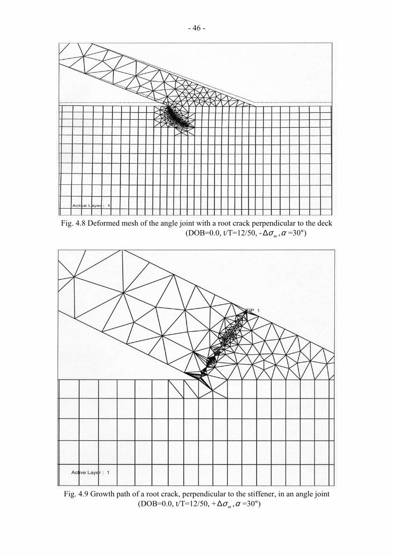
- 46 -
Fig. 4.8 Deformed mesh of the angle joint with a root crack perpendicular to the deck
(DOB=0.0, t/T=12/50, - ∆ , =30°) mσ α
Fig. 4.9 Growth path of a root crack, perpendicular to the stiffener, in an angle joint
(DOB=0.0, t/T=12/50, + ∆ , =30°) mσ α

- 47 -
Fig. 4.10 Growth path of a root crack, parallel to the surface of the deck, in an angle joint
(DOB=-1.0, t/T=12/50, + ∆ , =30°) mσ α
Fig. 4.11 Growth path of a root crack, parallel to the surface of the deck, in an angle joint
(DOB=0.0, t/T=35/50, + ∆ , =60°) mσ α

- 48 -
Fig. 4.12 Growth path of a toe crack, vertical to the surface of the deck, in an angle joint
(DOB=0.0, t/T=20/50, + ∆ , =30°) mσ α As previously discussed, the direction of the crack propagation was predicted by using the maximum circumferential stress theory. The local stress state at the crack tip controlled the fatigue crack growth behaviour in terms of crack growth direction, fatigue life and ultimately the fatigue strength of the joint. The stress state at the crack tip is, however, influenced by its instantaneous location and the structural dimension of the joint together with the type of applied load. Due to the complexity of the load carried and the locations of the pre-existing cracks, clearly, it was not intuitively obvious as to which of the pre-existing cracks was most critical for a given joint geometry. Case by case evaluation was required. 4.2.3 Butt Joint The fatigue strengths of two types of butt joints were calculated as part of this thesis work. The first is the butt joint welded from both sides but with partial penetration. The initial root cracks of the welds both sides were considered. The geometrical parameters and the load conditions of double-side welds butt joint are shown in Fig. 4.13 and Table 4.1.
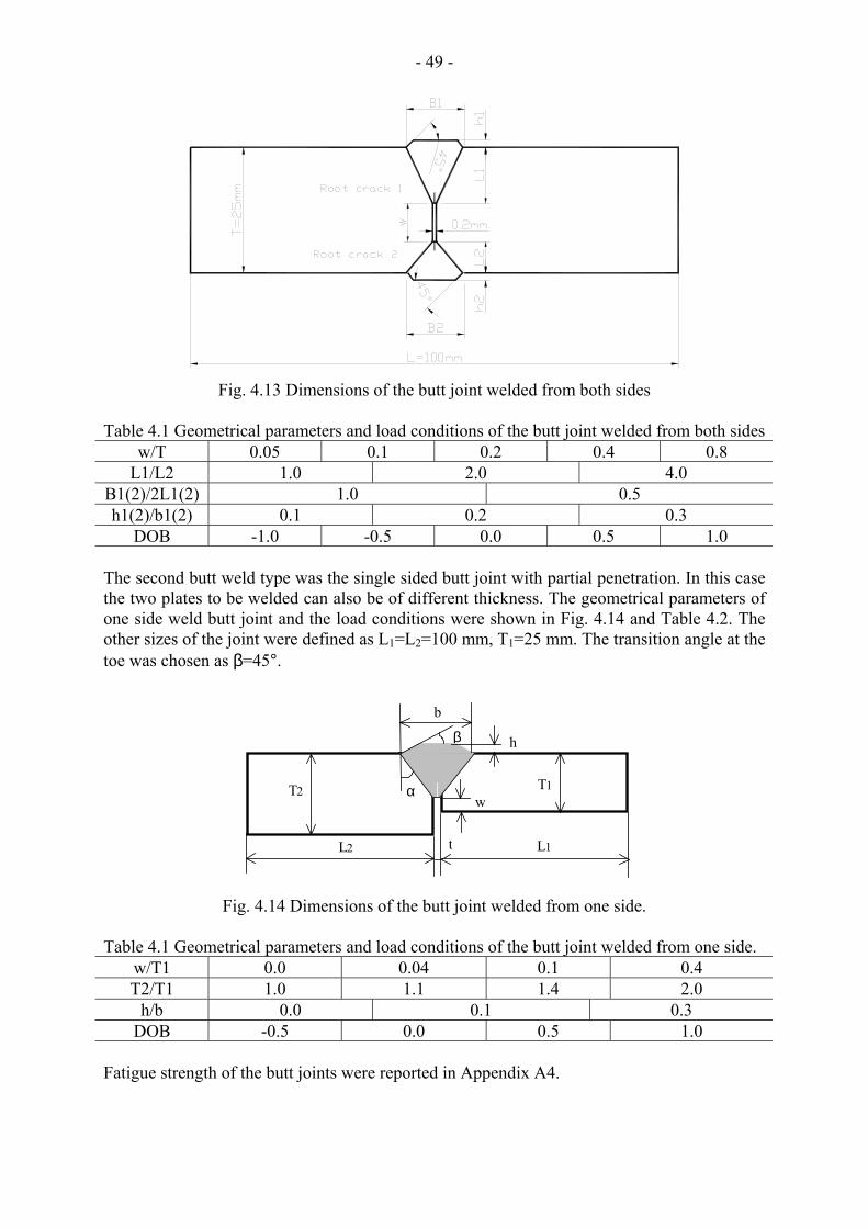
- 49 -
Fig. 4.13 Dimensions of the butt joint welded from both sides Table 4.1 Geometrical parameters and load conditions of the butt joint welded from both sides
w/T 0.05 0.1 0.2 0.4 0.8 L1/L2 1.0 2.0 4.0
B1(2)/2L1(2) 1.0 0.5 h1(2)/b1(2) 0.1 0.2 0.3
DOB -1.0 -0.5 0.0 0.5 1.0
The second butt weld type was the single sided butt joint with partial penetration. In this case the two plates to be welded can also be of different thickness. The geometrical parameters of one side weld butt joint and the load conditions were shown in Fig. 4.14 and Table 4.2. The other sizes of the joint were defined as L1=L2=100 mm, T1=25 mm. The transition angle at the toe was chosen as β=45°.
L1L2
T2 T1
b
β
αw
t
h
Fig. 4.14 Dimensions of the butt joint welded from one side.
Table 4.1 Geometrical parameters and load conditions of the butt joint welded from one side.
w/T1 0.0 0.04 0.1 0.4 T2/T1 1.0 1.1 1.4 2.0
h/b 0.0 0.1 0.3 DOB -0.5 0.0 0.5 1.0
Fatigue strength of the butt joints were reported in Appendix A4.

- 50 - 4.3 Analysis of Fatigue Crack Tip Fields by Elastic Plastic Fracture Mechanics (EPFM) Approach Linear elastic fracture mechanics (LEFM) can be usefully applied as long as the plastic zone is small compared to the crack size. This is usually the case in materials where fracture occurs at stresses appreciably below the yield stress and under conditions of plane strain. In such circumstances the fracture can be characterized by . When plane stress prevails the crack tip plastic zone is larger than in the case of plane strain. When the plastic zone is large compared to the crack size, linear elastic fracture mechanics does not apply.
ICK
In practice, welded joints frequently experience plane stress conditions and large deformation. Logically, it is necessary to find the satisfactory rationale ways to handle such problems. Nevertheless, an investigation regarding the mismatching influence on crack tip fields and fracture-characterizing parameters is needed before the above rational ways could be found. Some findings concerning the influence of mismatching on fatigue crack tip fields and the characteristic parameter, such as the J-integral, are presented briefly in this section with the details presented in Appendix 2. 4.3.1 Progressive Crack-tip Fields of Mismatched Specimens Finite element calculations were performed on the mismatched specimens shown in Fig. 3.1(b). The forward yielding in homogeneous specimens and sandwich specimens was calculated during the loading part of each cycle. In addition to the crack tip yielding, the localized yielding in the adjacent region was also found in overmatched specimens. The changes of the forward plastic zone due to the maximum applied cyclic load are schematically illustrated in Fig. 4.15.
Fig. 4.15 Schematic of forward plastic zone shape in an overmatched specimen during
fatigue crack growth. The crack opening displacement along the cracked surface was monitored during both the

- 51 - loading and unloading parts of the fatigue cycles. Plastic deformation in the wake of a fatigue crack was qualitatively studied by the compression of the crack profiles of both a fatigue crack and a stationary crack under the maximum applied cyclic load. This was believed to be the major reason for the observed fatigue crack closure. Due to the unique localized yielding in mismatched specimens, together with the influence of crack closure, compressive stresses were developed not only at the crack tip region but also along the closed fatigue crack surface upon complete removal of the applied load. The fatigue crack could be fully opened only after the above residual compressive stresses, both at the tip region and along the closed surface, were balanced by the applied tensile stress during subsequent reloading. Based on this consideration, the influence of mechanical mismatching on fatigue crack opening load was estimated by examination of the changes of crack opening displacements at the tip node, changes of stresses at the tip node and changes of contact stresses along the closed fatigue surface in reloading part of fatigue cycles. Consequently, fatigue crack closure was the primary reason as to why mechanical mismatching led to increased fatigue crack growth life. A part of the above results was reported in the published papers in Appendix 1 and the theoretical background is resented in Appendix 2. 4.3.2 Application of the J-Integral to the Fatigue Crack Growth of Mismatched Welds Both plasticity and unloading are characteristics of fatigue loading. These characteristics are contradictory to the original assumptions of the J-integral principle. However, Dowling [33] has correlated fatigue crack growth data with the cyclic J-integral range. Other researchers have also been attracted to the investigation of the influence of the cyclic plasticity on J as a means of characterizing crack extension. Attempts have also been made, in this thesis, to define the path dependency and independency of the J integral in characterizing crack growth in mismatched CCP specimens. Both the stationary cracks and fatigue cracks were considered as the path independency of the J-integral was evaluated in monotonic and cyclic loading conditions. The implementation of the J-integral into fatigue crack growth, in mismatched specimens is detailed in Appendix 2.

- 52 - 4.4 Summary The finite element method has been used to simulate the damage caused by micro-void coalescence in welded specimens based on continuum damage mechanics. The influence of geometric discontinuities including pre-existing crack-like defects on fatigue strength of welded joints was also systematically investigated using linear elastic fracture mechanics principles. To better understand the fatigue crack tip fields when LEFM assumptions are no longer valid, elasto-plastic fracture mechanics was also used. Gurson’s damage model and its modification were used to describe the nucleation and growth of micro-voids in ductile materials. A set of parameters for micro-void volume calculation and the failure criteria were defined. The methodology for prediction of fatigue life and fatigue strength of welded joints, based on Paris-Erdogan relation and IIW recommendations, was presented. This methodology was implemented in the parametric investigation of the influence of geometrical discontinuities and load condition on fatigue strengths of lap joints, angle joints and butt joints with the pre-existing crack-like defects. The application of elastic-plastic fracture mechanics in characterizing fatigue crack growth in mismatched specimens was briefly presented with details further reported in Appendix 2.

- 53 -
5 Conclusions The future of high technology welded constructions will be characterised by higher strength materials and improved weld quality with respect to fatigue resistance. Implementation of high quality high strength steel welds will require that more attention be given to the issues of crack initiation and mechanical mismatching. Root cracking and geometric mismatching is a continuous challenge in the production of economic and fatigue resistant welded joints. Work in this thesis can be subdivided into three major areas with the geometrical discontinuity dependency of fatigue strengths of welded joints subject to root cracking as one area, the mismatching effect of welded joints on crack initiation and low cycle fatigue as the second, and the effect of mechanical mismatching on fatigue crack growth behaviour as the third. Important findings have been published at international conferences and in technical journals. These publications are reproduced in Appendix A. FEM was the major tool used in the prediction of fatigue strengths of welded joints with geometrical discontinuities. The pre-existence of crack-like defects at both the weld toe and weld root were key characteristics of these joints. Geometrical parameters of typical joints, such as the thickness of the members to be jointed, the size and profile of welds were systematically varied with the goal of building a database for engineering use. Fatigue strengths of welded joints were predicted based on Paris-Erdogan relation and IIW recommendations. Loading included tensile, bending and various combinations of these two. The results can be assistance to designers making decisions regarding the proper choice of geometrical parameters of the as welded joints based on fatigue strengths. Also the degree of weld penetration needed to attain adequate fatigue strength can be assessed, thus, producing potential economic savings. The detailed results on lap joint, angle joint and butt joint were presented in the appended papers. By using experimental and finite element (FE) methods, the effects of mechanical mismatching on the initiation of micro voids was investigated within the framework of continuum damage mechanics. The damage mechanisms of mismatched specimens were analysed, with the help of the in-situ SEM observation in monotonic loading. The effect of mechanical mismatching on fatigue crack growth behaviour of welded joints was investigated both by experimental and elastic-plastic fracture mechanics (EPFM) approaches. The influence of mechanical mismatching on fatigue crack growth behaviour of welded joints was attributed to its influence on fatigue crack closure. The applying of the J integral concept into fatigue crack growth of welded joints was also evaluated.

- 54 - Summary of Appended Papers Seven papers were attached as appendix A of this thesis. In the first paper, the modified Gurson’s damage model was presented. Sandwich-like bi-material mismatching specimens were designed; the accumulation of micro voids in terms of void volume fraction was considered as a damage parameter for description of the nucleation and growth of micro voids in ductile materials. This was implemented in the FEM code MARC. The nominal longitudinal strain, at formation of the macro void, was suggested as a reasonable critical value for the assessment of damage resistance of a material. Damage resistance of the mismatching specimens was evaluated accordingly. In the second paper, the fatigue life and fatigue strength prediction procedure for parametric geometry analysis was presented. The concept FAT used by the IIW recommendations was also introduced. By using the FRANC 2D/L code, the influences of load conditions, weld sizes, the boundary constraints, the pre-existing of root crack and toe crack on fatigue strength of lap joint were computed. The influence of FE model size reduction, as it was used frequently in numerical simulations, on the accuracy of the results was analysed. The angle joint was chosen as the objective of paper 3. The mean fatigue strengths of such joints were predicted, with the consideration of the load conditions, joint geometry and dimensions, and the pre-existing of root crack and toe crack, based on the Paris-Erdogan relation and IIW recommendation. In paper 4, the fatigue strength of double-sided welded butt joints was estimated using finite element method and linear elastic fracture mechanics. The welded joints were considered as partially penetrated and with asymmetry of the two welds. The influence of the variation of the weld geometry and the carried loads on the fatigue strengths of the joints was assessed. The extent of lack of penetration expectedly had the most significant influence on fatigue strength of the joint. In paper 5, a systematic analysis of the geometrical discontinuity on fatigue strengths of several types of welded joints, including single fillet welded T-joint, corner joint, angle joint, cruciform joint with V-butt welds and partial penetration, cruciform joint with K-butt welds and partial penetration, T-joint with fillet welds, butt joint of double welds with partially penetration, butt joint of single weld with partially penetration, non-load carrying lap joint, butt joint with permanent backing bar, axially load carrying lap joint and axially load carrying double lap joint, were analysed in as welded condition. A maximum tangential stress criterion with the Paris crack growth law was used to predict the growth of a root crack and a toe crack under mixed mode KI - KII conditions. The effect of weld size and joint dimension ratios on the fatigue strength, were studied. In paper 6, the sandwich-like mismatch CCP specimen was presented. Fatigue crack growth tests were performed on overmatched CCP specimens with various sandwich layer widths. The influence of mechanical mismatching on fatigue crack growth rate and fatigue crack growth life was demonstrated experimentally. Fatigue crack surface profile and crack tip stresses distribution were analysed by finite element method. The residual plastic displacements in the wake of the fatigue crack were verified and were considered as the major cause of crack closure. Changes of the stress at the crack tip were analysed and a criteria in estimation of fatigue crack opening load was defined. The influence of mechanical mismatching on fatigue crack growth rate and fatigue crack growth life was interpreted by its

- 55 - influence on the criteria defined above. In paper 7, the localized yielding at the fatigue crack tip of sandwich CCP specimens was analysed. The forward plastic zone shapes were calculated and the changes of plastic zone shape in an overmatch CCP specimen were predicated. Contact stress distributions along the closed fatigue crack were calculated and the redistribution of the contact stresses during reloading were analysed. The crack opening process was illustrated. By examining the changes in crack tip displacement during loading, the crack tip opening loads were defined. Finally, the influence of mechanical mismatching on fatigue crack growth rate and fatigue crack growth life was attributed to its influence on fatigue crack closure.

- 56 - References [1] Wöhler, A., Tests to determine the forces acting on railway carriage axles and the
capacity of resistance of the axles, Abstract in Engineering, vol. 11, 1871, P.199. [2] Gurney, T. R., Fatigue of welded structures, Cambridge University Press, Cambridge,
England, 1979. [3] McHenry and Potter, (eds.), Fatigue and fracture testing of weldments, ASTM, STP
1058, 1990. [4] Karlsen, A. and Tenge, P., D/R Alexander L. Kielland, Estimation of fatigue cracks in
hydrophone region on brace D-6, Det Norske Cverita Report 80-0410, 1980. [5] ASME, Boiler and pressure code, section XI, rules for in-service inspection of nuclear
power plant components, 1992. [6] BS 5400: pt10, Steel, concrete and composite bridges; code of practice for fatigue, The
British Standards Institution, 1980. [7] BS PD 6493, Guidance on some methods for the derivation of acceptance levels for
defects in fusion welded joints, The British Standards Institution, 1991. [8] BS 5500, Unfired fusion welded pressure vessels, The British Standards Institution,
1985. [9] Hobbacher, H., Fatigue design of welded joints and components, Recommendations of
IIW joint working group XIII-XV, XIII-1539-96/XV-845-96, Abington Publishing. [10] Structural welding code D1.1, American Welding Society, New York, 1988. [11] Li, X. Y., Zhu, H. G. and Tian, X. T., A study of fatigue crack growth and crack
closure in mechanical heterogeneous welded joints, Engng. Fract. Mech., vol.55, no.4, 1996, pp.689-697.
[12] Buirette, C., Deqallaix, G., Dauphin, J. Y. and Menigault, J., Microstructural effects on short fatigue crack initiation and propagation in high strength steel butt welded joints, Welding in the World, Vol.41, No.1, 1998, pp.37-48.
[13] Christopher, B., Gregory, G. and John, P., Fatigue crack initiation and growth in A517 submerged arc welds under variable amplitude loading, Int. J. of Fatigue, Vol.22, No.9, 2000, pp. 799-808.
[14] Li, X. Y., Tian, X. T. and Zhu, H. G., Fatigue Crack Growth and Crack Closure of Simulated Over-Matched Welded Joints, ACTA Metallurgica Sinica (English Letters), Vol.13, No.1, 2000, pp.117-122.
[15] Kim, J. H., Oh, Y. J., Hwang, I, S., Kim, D. J. and Kim, J. T., Fracture behavior of heat-affected zone in low alloy steels, J. of Nuclear Mater., Vol.299, No.2, 2001, pp.132-139.
[16] Brandt U., Lawrence F. V. and Sonsino C. M., Fatigue crack initiation and growth in AlMg4.5Mn butt weldments, Fatigue & Frac. of Engng. Mater. & Struct., Vol.24, No.2, pp.117-126.
[17] Kin, I. T., Yamada, K., Kainuma, S., Fatigue behavior of butt welded joints containing inclined lack-of-penetration, Struct. Engng./Earthquake Engng., Vol.18, No.1, 2001, pp.53-62.
[18] Saiama, M. M., Fatigue crack growth behavior of titanium alloy Ti-6Al-4V and weldment, J. of Offshore Mechanics and Artic Engng., Vol.123, No.3, 2001, pp.141-146.
[19] Zhang, H. Q., Zhang, Y. H., Li, L. H. and Ma X. S., Influence of weld mis-matching on fatigue crack growth behavior of electron beam welded joints, Mater. Sci. & Engng., Vol.334, No.1-2, 2002, pp.141-146.
[20] Naiquan, Y. & Torgeir, M., Fatigue and static behavior of aluminium box-stiffener lap joints, Int. J. of Fatigue, Vol.24, No.5, 2002, pp.581-589.

- 57 - [21] Lindley, T. C., Richards, C. E. and Ritchie, R.O., The mechanics and mechanisms of
fatigue crack growth in metals, Metallurgia and Metal Forming, vol.43, pp. 268-272, 1976.
[22] Easterling, K., Introduction to the physical metallurgy of welding, London, Butterworths, 1985, pp.104.
[23] Gurson, A. L., Plastic flow and fracture behavior of ductile materials incorporating void nucleation, growth and interaction, PhD thesis, Brown University, June, 1975.
[24] Gurson, A. L., Continuum theory of ductile rupture by void nucleation and growth – I. Yield criteria and flow rules for porous ductile media, J. Engng Materials Technol., Vol. 99, No.1, pp.2-15, 1977.
[25] Tvergaard, V., Influence of voids on shear band instabilities under plane strain conditions, Int. J. Fracture, Vol.17, No.4, pp.389-407, 1981.
[26] Tvergaard, V., Material failure by void coalescence in localized shear bands, Int. J. Solids & Struct., Vol.18, No.8, pp. 659-672, 1982.
[27] Needleman A. and Rice, J. R., Limits to ductility set by plastic flow localization, Mechanics of Sheet Metal Forming (Edited by D. P. Koistinen et al.), pp.237-267, Plenum Press, New York, 1978.
[28] Hoeppner, D. W., editor, Fatigue testing of weldments, ASTM STP648, 1977. [29] Paris, P. C. and Erdogan, F., A critical analysis of crack propagation laws, Trans.
ASME, J. Basic Engng., vol.85, 1963, pp.528-534. [30] Meguid, S. A, Engineering Fracture Mechanics, Elsevier Applied Science, 1989,
p.211. [31] Rice, J. R., A path independent integral and the approximate analysis of strain
concentration by notches and cracks, J. Appl. Mech., vol.35, 1968, pp.379-386. [32] Wells, A. A., Unstable crack propagation in metal: damage and fast fracture, Proc.
Crack Propagation Symposium, Granfield, vol. 1, 1962, pp.210-230. [33] Dowling, N. E. and Begley, J. A., Fatigue crack growth during gross plasticity and the
J integral, in Mechanics of Crack Growth, ASTM STP590, 1976, pp.82-103. [34] Dowling, N. E., Geometry effects and the J-integral approach to elastic-plastic fatigue
crack growth, in Crack and Fracture, ASTM STP601, 1976, pp.19-32. [35] Harrison, J. D., Burdekin, F. M. and Young, J. G., A proposed acceptance standard for
weld defects based upon suitability for service, 2nd Conference on the Significance of Defects in Welded Structures, The Welding Institute, London, England, 1968.
[36] Burdekin, F. M. and Dawes, M. G., Practical use of linear elastic and yielding fracture mechanical with particular reference to pressure vessels, Conference on application of fracture mechanics to pressure vessel technology, Institution of Mechanical Engineers, London, England, May, 1971.
[37] Dawes, M. G., Fracture control in high yield strength weldments, Welding Journal Research Supplement, vol. 53, pp.369s-379s, 1974.
[38] Dawes, M. G., The COD design curve, in Advances in Elasto-plastic Fracture Mechanics (editor Larsson, L. H.), Applied Science Publishers, pp.279-300, 1980.
[39] Schwalbe, K. H., The engineering flaw assessment method (EFAM)-Document EFAM 96, GKSS-Forschungszentrum Geesthacht GmbH, Geesthacht, 1998.
[40] Elber, W., Fatigue crack closure under cyclic tension, Engng. Fract. Mech., Vol.2, pp.37-45, 1970.
[41] Elber, W., The significant of fatigue crack closure, in Damage Tolerance in Aircraft Structures, ASTM STP486, pp.230-262, 1971.
[42] Budiansky, B. and Hutchinson, J. W., Analysis of closure in fatigue crack growth, J. Appl. Mech., vol.45, pp.267-280, 1978.
[43] Newman Jr., J. C., A crack closure model for predicting fatigue crack growth under aircraft spectrum loading, ASTM STP 748, pp.53-84, 1981.

- 58 - [44] Ritchie, R. O., Influence of microstructure on near-threshold fatigue crack propagation
in ultra-high strength steel, Metal Science, Vol.11, pp.368-381, 1977. [45] Lindley, T. C: and Richards, C. E., The relevance of crack closure to fatigue crack
propagation, Materials Science and Engineering, vol.14, pp.281-293, 1974. [46] Newman Jr., J. C., A crack opening stress equation for fatigue crack growth, Int. J.
Fract., vol.24, pp.131-135, 1984. [47] Walker, N. and Beevers, C. J., A fatigue crack closure mechanism in titanium, Fatigue
of Engineering Materials and Structures, vol.1, pp.135-148, 1979. [48] Chalant, G. and Remy, L., Plastic strain distribution at the tip of a fatigue crack,
application to fatigue crack closure in the threshold regime, Engng. Fract. Mech., vol.16, pp.707-720, 1982.
[49] Lee, E. W., Chakrabortty, S. B. and Starke, E. A., The effect of overload on the fatigue crack propagation in metastable beta Ti-V alloys, Metallurgical Transactions, 15A, pp.511-517, 1984.
[50] Newman, J and Elber, W. (eds.), Mechanics of Fatigue Crack Closure, ASTM STP 982, 1988.
[51] Ritchie, R. O., Suresh, S. and Moss, C. M., Near-threshold fatigue crack growth in 2
41 Cr-1Mo pressure vessel steel in air and hydrogen, Journal of Engineering
Materials and Technology, Vol. 102, pp.293-299, 1980. [52] Suresh, S. and Ritchie, R. O., A geometric model for fatigue crack closure induced by
facture surface roughness, Metallurgical Transaction 13A, pp.1627-1631, 1982. [53] Niemi, E., Stress Determination for Fatigue Analysis of Welded Components, IIS/IIW-
1221-93 (ex doc XIII-1458-92, XV-797-92), Abington Publishing, 1995. [54] Gurney, T. R., Fatigue of Welded Structures, Second Edition, Cambridge University
Press, Cambridge, 1979. [55] Kalpakjian, S., Manufacturing Engineering and Technology, Addison-Wesley, 2002. [56] Гpaσuң, B. Ф. and Бедоцқuủ, A. B., Welding Metallurgy for Low Alloyed and Middle
Alloyed Steels, Science and Technology Publisher, Shanghai, 1983 (in Chinese), p.185 [57] Satoh, K., Welding Engineering, Science and Technology Publisher, Japan, 1979 (in
Japanese) [58] Satoh, K., Toyoda, M., Minami, F., Nakanishi, M., Arimochi, K., Effect of Mechanical
Heterogeneity on Fracture Toughness Evaluation of Steel Welds, Trans. Japan Welding Society, Vol.16, No.2, pp.74/81, 1985.
[59] Thaulow, C., Toyoda, M., Strength Mismatching Effect on Fracture Behaviour of HAZ, IIW Doc. X-F-033-96, 1996.
[60] Minami, F., Yoyoda, M., Thaulow, C., Hauge, M., Effect of Strength Mismatch on Fracture Mechanical Behaviour of HAZ-notched Welded Joint, Quarterly Journal Japan Welding Society, Vol.13, No.4, pp.508-517, 1995.
[61] Tian, X., The Effect of Mechanical Heterogeneity on Fracture and Fatigue of Welded Joints and Their Reliability Assessment – A Survey of Researches in China, New Advances in Welding and Allied Processes, Proceedings of the International Conference, International Academic Publishers, pp.19-27, 8-10 May, 1991.
[62] Defourny, J., D’Haeyer, R., Mismatch in High Strength Steel Welds, Highlights of the ECSC F1 & F% Workshop, Brussels, Technical Steel Research Final Report, EUR 16029 EN, 7 December, 1993.
[63] Ainsworth, R. A., Lei, Y., Strength Mis-Match in Estimation Schemes, IIW Doc. X-F-034-96, 1996.
[64] Joch, J. Ainsworth, R. A., Relationship Between the J-integral and The Crack Tip Opening Displacement for Stationary Cracks in Weldments at Plastic Collapse, Fatigue Fract. Engng Mater. Struct., Vol.17, pp.1175-1185, 1994
[65] Mukai, Y. and Nishimura, A., Fatigue crack propagation behaviour in hardness

- 59 -
heterogeneous field, Transactions of the Japan Welding Society, Vol.14, No.1, pp.18-26, 1983
[66] Schwalbe, K. –H., Kim, Y. –J., Hao, S., Cornec, A., and Kocak, M., ETM-MM 96 – The ETM Method for Assessing the Significance of Crack-like Defects in Joints with Mechanical Heterogeneity (Strength Mismatch), GKSS Report 97/E/9, GKSS-Forschungszentrum, Geesthacht, 1997.
[67] Dogan, B., Comparison of the Defect Assessment Procedures, EC supported project “Plant Life Assessment Network”, Document No.: PLAN.CT C2 DOC 01.05 Version 1, 18 May, 2001.
[68] MARC Manual, Volume A: Theory and user information, Version K7, pp.7.100-7.102,1998.
[69] Brown, L. M. and Embury, J. D., The initiation and growth of voids at second phase particles, Proc. 3rd Int. Conf. On Strength of Metals and Alloys, Inst. Of Metals, London, pp.164-169, 1973.
[70] Goods, S. H. and Brown, L. M., The nucleation of cavities by plastic deformation, Acta Metallurgica, Vol.27, pp.1-15, 1979.
[71] Mori, T., and Ichimiya, M, Fatigue crack initiation point in load carrying fillet-welded cruciform joints, Welding International, vol. 13, No. 10, pp.786-794, 1999.
[72] Peeker, E., Niemi, E., Fatigue crack propagation model based on a local strain approach, J. of Construction Steel Research, vol. 49, pp.139-155, 1999.
[73] Balasubramanian, V. and Guha, B., Analysing the influences of weld size on fatigue life predication of FCAW cruciform joints by strain energy concept. Int. J. of Pressure Vessels and Piping, vol. 76, pp.759-768, 1999.
[74] Lee, M.M.K., Strength, stress and fracture analysis of offshore tubular joints using finite elements, J. of Construction Steel Research, vol.51, pp.265-286, 1999.
[75] Nykänen, T., Lihavainen, V., Geometric dependency of fatigue strength in a transverse load-carrying cruciform joint with partially penetrating V-welds, IIW Doc. XIII-1838-00, 2000.
[76] Bell, R., Vosikovsky, O., Burns, D.J., Mohaupt, U.H., A fracture mechanics model for life prediction of welded plate joints, Proc. 3rd Int. ESCS Offshore conf. On Steel in Marine Structures (SIMS’87), Delft, The Netherlands, ed. C. Noordhoek and J. de Back, pp.901-910, June 15-18, 1987.
[77] Smith, T.J., and Hurworth, S.J., The effect of geometry changes upon the predicted fatigue strength of welded joints, Report of The Welding Institute, No. 224, UK, 1984.
[78] Nykänen, T., Lihavainen, V., Geometric dependency of fatigue strength in a transverse load-carrying cruciform joint with partially penetrating V-welds, IIW Doc. XIII-1838-00, 2000.
[79] Li, X.Y., Partanen, T., Nykänen T., and Björk T., Finite Element Analysis of The Effect of Weld Geometry and Load Condition on Fatigue Strength of Lap Joint, Int. J. for Pressure Vessels and Piping, vol. 78/9, pp.591-597, 2001.
[80] Li, X. Y., Partanen, T., Nykänen, T. and Björk, T., Evaluation of Fatigue Strength of Angle Joint with Fully Penetration, Proceedings of the 7th International Symposium of Japan Welding Society in the Theme “Today and Tomorrow in Science and Technology of welding and Joining”, Kobe, Japan, Vol.2, Editor T. Ohji, pp.1225-1230, 20-22 November, 2001.
[81] Li, X. Y., Nykänen, T., Björk T. and Marquis, G., Fracture Mechanics Analysis of Partial Penetrated Butt Welds, Design and Analysis of Welded High Strength Steel Structures, Editor J. Samuelsson, Fatigue 2002, Held in Stockholm, Sweden, pp.139-149, 3-7 June, 2002.
[82] Maddox, S. J., Assessing the significance of flaws in welds subject to fatigue, Weld. Res. Supplement, Vol.53, No.9, 1974, pp.401-409

- 60 - [83] Bell, R., Vosikovsky, O., Burns, D.J., and Mohaupt, U.H., A fracture mechanics model
for life prediction of welded plate joints, Proc. 3rd Int. ESCS Offshore conf. On Steel in Marine Structures (SIMS’87), Delft, The Netherlands, ed. C. Noordhoek and J. de Back, pp.901-910, June 15-18, 1987.
[84] Smith, T.J., and Hurworth, S.J., The effect of geometry changes upon the predicted fatigue strength of welded joints, Report of The Welding Institute, No. 224, UK, 1984.
[85] Det norske Veritas (DnV), Rules for the design construction and inspection of offshore structures, App. C. Steel Structures, Hövik, 56p., 1982.
[86] Swenson D, James M, FRANC2D/L: A crack propagation simulator for plane layered structure, version 1.4 User’s Guide, Kansas State University, Manhattan, Kansas, 1997
[87] Dodds, R. H. and Vargas, P. M., Numerical evaluation of domain and contour integral for non-liner fracture mechanics: formulation and implementation aspects, Report from University of Illinois at Urbana-Champaign, Dept. of Civil Engineering, 1988.
[88] James M, A plane stress finite element model for elastic-plastic mode I/II crack growth, PhD Dissertation, Kansas State University, 1998.
[89] Erdogan F, Sih GC, On the crack extension in plates under plane loading and transverse shear, ASME J Basic Engng., vol.85, pp.519-527, 1963.
[90] Nykänen, T. and Björk, T., X-FAT koulutus, HRO Teemapäivät 2001, Lappeenrannan Teknillinen Korkeakoulu, 13-14 June, 2001 (in Finnish)
[91] Newman, J. C. Jr., A finite-element analysis of fatigue crack closure, Mechanics of Crack Growth, ASTM STP 590, pp.281-301, 1976.
[92] Nakagaki, M. and Alturi, S. N., Elastic-plastic finite element analyses of fatigue crack growth in mode I and mode II conditions, NASA contractor report 158987, NASA Grant NSG-1351, November 1978.
[93] Broek, David, Elementary Engineering Fracture Mechanics, 3rd Edition, Martinus Nijhoff Publishers, p.222, 1984.
[94] McMeeking, R. M., Path dependence of J integral and the role of J as a parameter characterizing the near-tip field, ASTM STP631, pp.28-41, 1977.
[95] Ma, W. D, A Study of Fracture Parameters of Heterogeneous Welded Joints, PhD thesis, Haribin Institute of Technology, P. R. China (In Chinese), 1985.
[96] Hayashi, K. and Horikawa, K.,Study on J-integral for a crack in heterogeneous materials, Materials, Vol.36, No.403, pp.341-347 (in Japanese)
[97] Zhang, S.C., Influence of Mechanical Heterogeneity of Welded Joints on Elasto-Plastic Fracture Characterizing Parameters, PhD thesis, Haribin Institute of Technology, P. R. China (In Chinese), 1987.
[98] Chen, W. H., Trans., Path Independency of the J-integral for Heterogeneous Cracked Bodies, 5th Int. Conf., SMIRT M9/4, 1, 1979.
[99] Miyamoto, H. and Kikuchi, M., Numerical Methods in Fracture Mechanics, Pineridge Press, p.359, 1980
[100] Park, D. M., Some problems in elastic-plastic finite elements analysis of cracks, Int. J. Fatigue, 1979.
[101] McMeeking, R. M., Finite deformation analysis of crack tip opening in elastic-plastic materials and implication for fracture initiation, J. Mech. Phy. Solids, 1976.
[102] Nakagaki, M., Cjem, W. H. and Atluri, S. N., A finite-element analysis of stable crack growth –I, ASTM STP668, pp-195-213, 1979.
[103] Begley, J. A., and Landes, J. D., The J integral as a fracture criterion in fracture toughness testing, ASTM STP514, pp.1-20, 1972.
[104] Paris, P. C., Fracture Mechanics in the Elastic-Plastic Regime, ASTM STP631, pp.3-27, 1977
[105] Gilles, P., Franco, C., A new J-estimation scheme for cracks in mis-matching welds – the ARAMIS method. In: Schwalbe, K. H. and Kocak, M., editors, Mismatching of welds, London, Mechanical Engineering Publications, pp.661-683, 1994.

- 61 - [106] Eripret, C., Hornet, P., prediction of overmatching effects on the fracture of stainless
steel cracked welds, In: Schwalbe, K. H. and Kocak, M., editors, Mismatching of welds, London, Mechanical Engineering Publications, pp.685-708, 1994.
[107] Hornet, P., Eripret, C., Experimental J evaluation from a load-displacement curve for homogeneous and over-matched SENB or CCT specimens, Fatigue and Fracture in Engineering Materials and Structures, Vol.18, No.6, pp.679-692, 1995.
[108] Schwalbe, K. H., The engineering flaw assessment method (EFAM)-Document EFAM 96, GKSS- Forschungszentrum Geesthacht Gmbh, Geesthacht, GKSS 98/E/40, 1998.
[109] Joch, J., Ainsworth, R. A., Hyde, T. H., Limit load and J-estimates for idealized problems of deeply cracked welded joints in plane strain bending and tension. Fatigue and Fracture in Engineering Materials and Structures, Vol.16, No.16, pp.1061-1079, 1993.
[110] Wang, Y. Y., Kirk, M. T., Geometry effects on failure assessment diagram, In: Proceedings of second international symposium on mis-matching of welds, Reinstorf-Luneburg, Germany, 1996.
[111] Lei, Y., Ainsworth, R. A., A J-integral estimation method for cracks in welds with mismatched mechanical properties, International Journal of Pressure Vessels and Piping, Vol.70, pp.237-245, 1997.
[112] Lei, Y., Ainsworth, R. A., The estimation of J in three-point-bend specimens with a crack in a mismatched weld, International Journal of Pressure Vessels and Piping, Vol.70, pp.247-257, 1997.
[113] Yagawa, G., Study on elastic-plastic fracture mechanics in inhomogeneous materials and structures, Final Report Prepared by EPI subcommittee, Nuclear Engineering Research Committee, The Japan Welding Engineering Society, JWES_AE9405, March, 1994.
[114] Francis, M., Rahman, S., Probabilistic analysis of weld cracks in center-cracked tension specimens, Computers and Structures, Vol.76, pp.483-506, 2000.


Appendix A
Appended Publications A1. X. Y. Li, Q. Hao, Y. W. Shi, Y. P. Lei and G. Marquis, Influence of Mechanical
Mismatching on the Failure of Welded Joints by Void Nucleation and Coalescence, International Journal of Pressure Vessels and Piping, 80 (2003), pp.647-654
A2. X. Y. Li, T. Partanen, T. Nykänen and T. Björk, Finite Element Analysis of the
Effect of Weld Geometry and Load Condition on Fatigue Strength of Lap Joint, International Journal of Pressure Vessels and Piping, 78 (2001), pp.591-597
A3. X. Y. Li, T. Partanen, T. Nykänen and T. Björk, Evaluation of Fatigue Strength of
Angle Joint with Fully Penetration, Proceedings of the 7th International Symposium of Japan Welding Society in the Theme “Today and Tomorrow in Science and Technology of welding and Joining”, 20-22 November, 2001, Kobe, Japan, Vol.2, Editor T. Ohji, pp.1225-1230
A4. X. Y. Li, T. Nykänen, T. Björk and G. Marquis, Fracture Mechanics Analysis of
Partial Penetrated Butt Welds, Design and Analysis of Welded High Strength Steel Structures, Editor J. Samuelsson, Papers Presented in Conjunction with the Eighth International Fatigue Congress, Fatigue 2002, Held in Stockholm, Sweden, 3-7 June, 2002, pp.139-149
A5. T. Nykänen, X. Y. Li, T. Björk and G. Marquis, A parametric fracture mechanics
analysis of welded joints in as welded condition, (submitted to Engng. Fract. Mech.)
A6. Li, Xiaoyan, Zhu, Hongguan and Tian, Xitang; A Study of Fatigue Crack Growth
and Crack Closure in Mechanical Heterogeneous Welded Joints, Engineering Fracture Mechanics, Vol.55, No.4, 1996, pp.689-697
A7. X. Y. Li, X. T. Tian and H. G. Zhu, Fatigue Crack Growth and Crack Closure of
Simulated Over-Matched Welded Joints, ACTA Metallurgica Sinica (English Letters), Vol.13, No.1, 2000, pp.117-122