Effect of Marine Environment to the Concrete Beams ...ijetch.org/vol7/759-R012.pdf · strength...
4
Abstract—Structures built in aggressive environments such as in the sea/marine environment need to be carefully designed, due to possibility of chloride ion penetration into the concrete. One way to reduce the strength degradation in such environment is to use FRP, which is attached to the surface of R/C using epoxy. The study presented is focused on determining the effect of the sea water to the capacity of GFRP as flexural reinforcement elements. Beams of 10×10×40 cm dimension were designed without reinforcing bars. The samples were tested using variation to the distance to the sea and duration of the contact to the sea. The result showed that the use GFRP increased the flexural strength 84,21%, compared to the normal beam, without GFRP. It can also be seen that the closer the distance to the sea, the higher the strength degradation of the beam. The sample rinsed in the water has strength 2.13 kN after 9 months, while sample put at a distance 1 km from the seam has strength 2.53 kN. The result of this study also showed that for areas closer to the sea has a greater effect in terms decreasing flexural capacity of the beam Index Terms—Flexural strength, GFRP, marine environment. I. INTRODUCTION Recently present the construction of the concrete structures around the beach line or even under water is increasing such as buildings, bridges, highway road, etc. Concrete structures that are not protected or close to the sea may be affected by corrosion, than if maintenance or preventive repairs is not done on the structure, it may cause the collapse [1]. Fiber Reinforced Plastics (FRP) has been accepted as an alternative material for the conventional steel reinforcement. Common FRP types are aramyd fiber reinforced plastic (AFRP), glass fiber reinforced plastics (GFRP), carbon fiber reinforced plastic (CFRP), respectively. FRP has been applied to many purposes for civil engineering structures not only for new structures but also for strengthening of the deteriorated structures. There has been an important increase in the use of FRP as strengthening structures with externally bonded, because of their inherent advantages in terms of light weight, high specific strength and stiffness ratios and their non corrosive properties [2], [3]. FRP has been developed in the various forms, such as grid, rod, sheet and plate. Glass fiber sheet as showed in Fig. 1 is most commonly used due to its relatively lower cost compared to the other FRP materials. Fig. 1. Glass fiber sheet. TABLE I: VARIATIONS IN BEAMS SPECIMEN Name of Specimen Initial Distance from the beach line (m) BN Beam without GFRP external reinforcement ----- BF Beam with GFRP external reinforcement ---- BF-1 Beam with GFRP external reinforcement Under water BF-2 Beam with GFRP external reinforcement 0 BF-3 Beam with GFRP external reinforcement 250 BF-4 Beam with GFRP external reinforcement 500 BF-5 Beam with GFRP external reinforcement 1000 Studies using retrofitting of beams have been conducted by several researchers. Banthia (2009) reported that using GFRP composite materials in the area interested in the beams and plates. The increase of the moment capacity [4]. Rose et al., (2009) demonstrated that the strengthening of the corroded steel reinforced concrete increased ductility and ultimate strength [5]. Z. G. Guo et al., (2005) reported that using FRP composites were successfully used for strengthening of existing reinforced concrete structures because of their superior properties [6]. Alam F (2010) conducted research using GFRP as reinforcement flexural in reinforced concrete beams, The result indicated is an increasing in load up to 75.13 % [7]. However further study needed to clarify the behaviour of beams with GFRP sheet reinforcement influenced by the marine environment. II. SPECIMEN AND TEST SETUP A. Specimen Fig. 2 shows the details of the test specimen. Concrete beams are prepared for this study with parameters of the bonding area GFRP sheet. The specimens were divided two types, which are strengthened reinforced external (BF) and Effect of Marine Environment to the Concrete Beams Strengthened Using GFRP Sheet Mufti Amir Sultan, Herman Parung, Wihardi Tjaronge, and Rudy Djamaluddin 21 IACSIT International Journal of Engineering and Technology, Vol. 7, No. 1, February 2015 DOI: 10.7763/IJET.2015.V7.759 Manuscript received March 15, 2014; revised May 27, 2014. This work was supported financially by the Directorate of Higher Education of Indonesia. The authors are with the Civil Engineering Department of Hasanuddin University, Makassar, South Sulawesi, Indonesia (e-mail: [email protected], [email protected], [email protected], [email protected]).
Transcript of Effect of Marine Environment to the Concrete Beams ...ijetch.org/vol7/759-R012.pdf · strength...

Abstract—Structures built in aggressive environments such as
in the sea/marine environment need to be carefully designed, due
to possibility of chloride ion penetration into the concrete. One
way to reduce the strength degradation in such environment is
to use FRP, which is attached to the surface of R/C using epoxy.
The study presented is focused on determining the effect of the
sea water to the capacity of GFRP as flexural reinforcement
elements. Beams of 10×10×40 cm dimension were designed
without reinforcing bars. The samples were tested using
variation to the distance to the sea and duration of the contact to
the sea.
The result showed that the use GFRP increased the flexural
strength 84,21%, compared to the normal beam, without GFRP.
It can also be seen that the closer the distance to the sea, the
higher the strength degradation of the beam. The sample rinsed
in the water has strength 2.13 kN after 9 months, while sample
put at a distance 1 km from the seam has strength 2.53 kN. The
result of this study also showed that for areas closer to the sea
has a greater effect in terms decreasing flexural capacity of the
beam
Index Terms—Flexural strength, GFRP, marine
environment.
I. INTRODUCTION
Recently present the construction of the concrete structures
around the beach line or even under water is increasing such
as buildings, bridges, highway road, etc. Concrete structures
that are not protected or close to the sea may be affected by
corrosion, than if maintenance or preventive repairs is not
done on the structure, it may cause the collapse [1].
Fiber Reinforced Plastics (FRP) has been accepted as an
alternative material for the conventional steel reinforcement.
Common FRP types are aramyd fiber reinforced plastic
(AFRP), glass fiber reinforced plastics (GFRP), carbon fiber
reinforced plastic (CFRP), respectively. FRP has been
applied to many purposes for civil engineering structures not
only for new structures but also for strengthening of the
deteriorated structures. There has been an important increase
in the use of FRP as strengthening structures with externally
bonded, because of their inherent advantages in terms of light
weight, high specific strength and stiffness ratios and their
non corrosive properties [2], [3]. FRP has been developed in
the various forms, such as grid, rod, sheet and plate. Glass
fiber sheet as showed in Fig. 1 is most commonly used due to
its relatively lower cost compared to the other FRP materials.
Fig. 1. Glass fiber sheet.
TABLE I: VARIATIONS IN BEAMS SPECIMEN
Name of
Specimen Initial
Distance from the
beach line
(m)
BN Beam without GFRP external
reinforcement
-----
BF Beam with GFRP external
reinforcement
----
BF-1 Beam with GFRP external
reinforcement Under water
BF-2 Beam with GFRP external
reinforcement 0
BF-3 Beam with GFRP external
reinforcement 250
BF-4 Beam with GFRP external
reinforcement 500
BF-5 Beam with GFRP external
reinforcement 1000
Studies using retrofitting of beams have been conducted by
several researchers. Banthia (2009) reported that using GFRP
composite materials in the area interested in the beams and
plates. The increase of the moment capacity [4]. Rose et al.,
(2009) demonstrated that the strengthening of the corroded
steel reinforced concrete increased ductility and ultimate
strength [5]. Z. G. Guo et al., (2005) reported that using FRP
composites were successfully used for strengthening of
existing reinforced concrete structures because of their
superior properties [6]. Alam F (2010) conducted research
using GFRP as reinforcement flexural in reinforced concrete
beams, The result indicated is an increasing in load up to
75.13 % [7]. However further study needed to clarify the
behaviour of beams with GFRP sheet reinforcement
influenced by the marine environment.
II. SPECIMEN AND TEST SETUP
A. Specimen
Fig. 2 shows the details of the test specimen. Concrete
beams are prepared for this study with parameters of the
bonding area GFRP sheet. The specimens were divided two
types, which are strengthened reinforced external (BF) and
Effect of Marine Environment to the Concrete Beams
Strengthened Using GFRP Sheet
Mufti Amir Sultan, Herman Parung, Wihardi Tjaronge, and Rudy Djamaluddin
21
IACSIT International Journal of Engineering and Technology, Vol. 7, No. 1, February 2015
DOI: 10.7763/IJET.2015.V7.759
Manuscript received March 15, 2014; revised May 27, 2014. This work was supported financially by the Directorate of Higher Education of Indonesia.
The authors are with the Civil Engineering Department of Hasanuddin University, Makassar, South Sulawesi, Indonesia (e-mail: [email protected], [email protected], [email protected], [email protected]).
22
IACSIT International Journal of Engineering and Technology, Vol. 7, No. 1, February 2015
beam without the external reinforcement (BN). Table I shows
variation specimen beams. The cross section of beam
specimens was 10 ×10 mm with the total length of 400 mm.
The concrete beams were cured before the application of the
GRFP sheet. Compressive strength of concrete at 28 days was
25 MPa.
400
100
A
5050 100100 100
100
GFRP
GFRP
400
100
A
5050 100100 100
100
(a) Type I : BN (Beam not reinforcement)
(b) Type II : BF (Beam with GFRP extrenal reinforcement)
Section A-A
Section A-A
Fig. 2. Detail of specimens.
Before the application of GFRP sheet, the bottom surfaces
of the beam were smoothed by a disk sander. The epoxy resin
was applied on the GFRP sheet placed on the table using a soft
roller to impregnate all the fibers in the resin. The epoxy resin
was applied on the treated surface using a soft roller before
patching of the impregnated GFRP sheet to the treated surface.
Fig. 3 shows installation of GFRP sheet on the beam.
Fig. 3. Installation of GFRP sheet on the beam.
The patched GFRP sheet was positioned with the
application of slight pressure using a soft roller. Table II
shows the material properties of the manufacturer data GFRP
sheet, and Table III shows the manufacturer data of epoxy
resin, respectively.
TABLE II: MATERIAL PROPERTIES OF GFRP
Items Glass Fiber
Tensile strength (MPa) 22.20
Modulus Young (GPa) 22.14
Laminate Thickness (mm) 3.3
TABLE III: MATERIAL PROPERTIES OF EPOXY RESIN
Items Properties
Tensile strength (MPa) 72.4
Modulus Young (GPa) 3.18
Bending Strength* (MPa) 2.12* Based on the tensile test
B. Test Setup
At this study, the beam specimens are placed at five
locations as follows: under water, the beach line, 250 m, 500
m and 1000 m from beach line. Beam specimens were placed
for one, three, six and nine months. Fig. 4 shows location the
placement of the sample.
PenghIbur
street
Port ofMakassar
1 5432
Building
Beach line
1. at under water
3. 250 m from the beach line2. on the beach line
5. 1000 m from the beach line4. 500 m from the beach line
Fig. 4. Location the placement of the samples.
Dail gaugeA
Manometer
Section A-A
Fig. 5. Test setup.
The beams specimens were tested under simple supported
beams subjected to two point loads using a universal testing
machine, as shown in Fig. 5. Each specimen was instrumented
by dial gauges and manometer, respectively. The deflection
and loading were measured using dial gauge and manometer.
III. RESULT AND DISCUSSION
A. Flexural Capacities
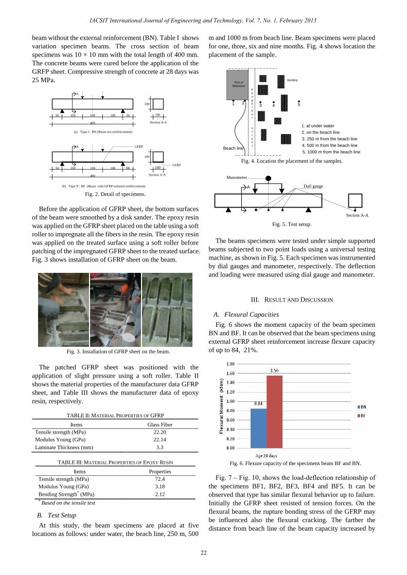
Fig. 6 shows the moment capacity of the beam specimen
BN and BF. It can be observed that the beam specimens using
external GFRP sheet reinforcement increase flexure capacity
of up to 84, 21%.
Fig. 6. Flexure capacity of the specimens beam BF and BN.
the specimens BF1, BF2, BF3, BF4 and BF5. It can be
observed that type has similar flexural behavior up to failure.
Initially the GFRP sheet resisted of tension forces. On the
flexural beams, the rupture bonding stress of the GFRP may
be influenced also the flexural cracking. The farther the
distance from beach line of the beam capacity increased by
Fig. 7 – Fig. 10, shows the load-deflection relationship of

18.75%
Fig. 7. Load-deflection curve (one month).
Fig. 8. Load-deflection curve (three months).
Fig. 9. Load-deflection curve (six months).
Fig. 10. Load-deflection curve (nine months).
Table III presents the decrease in the maximum deflection
and maximum moment capacity of specimen after 6 months
on average 1.87% and 8.75%. This indicates that after 6
months of contact with the marine environment beam strength
degradation.
TABLE IV: SUMMARY OF MOMEN MAXIMUM AND DEFLECTION MAXIMUM
Specimen
Contact duration
of the marine
environment
(month)
Maximum
moment
(kN.m)
Deflection at
Mmax
(mm)
BF1
1 1.58 0.720
3 2.00 1.080
6 2.16 1.310
9 2.13 1.290
BF2
1 1. 82 0.810
3 2.16 0.141
6 2.44 1.420
9 2.38 1.390
BF3
1 1.89 1.050
3 2.27 1.25
6 2.40 1.450
9 2.37 1.320
BF4
1 2. 11 1.080
3 2.27 1.320
6 2.47 1.700
9 2.40 1.320
BF5
1 2.13 1.070
3 2.49 1.600
6 2.57 1.450
9 2.53 1.430
B. Effect of Distance
Fig. 11 and Fig. 12, show that after 6 months reduces the
flexural capacity of an average of 1.87%. Sample at a distance
of 1000 m from the line beach to the load capacity reduction is
of 1.32% compared to that located on the line beach of 2.80%.
This indicates that the reduction in beam flexural capacity is
greater for areas and closer to the sea.
Fig. 11. relationship the flexural moment and the distance from the beach
line.
C. Failure Mode
Based on the results of flexural was testing of specimen
beams as shown in Fig. 9, pattern of cracks occurred at the 1/3
of the span, so it can be said to be cracked due to flexural
moment. The results of these observations are also the basis
for the calculation of flexural strength by using the
appropriate formula references used.
In this test the beam flexural fractured, It can be seen from
the crack pattern direction vertical to the longitudinal axis of
the beam. Crack generally occurs at the mid span right under
23
IACSIT International Journal of Engineering and Technology, Vol. 7, No. 1, February 2015

load. If the load continues to increase and the cracks are
already beginning to happen more and more length to the
width and cross section neutral axis, thereby reducing the
stiffness of the beam.
Fig. 12. Load-deflection curve (BF 5).
Fig. 12. specimen beam pattern collapse.
IV. CONCLUSION
This study revealed that concrete beams with GFRP
external reinforcement flexural strength increased by 84.21%,
The sample rinsed in the water has strength 2.13 kN after 9
months, while sample put at a distance 1 km from the sea has
strength 2.53 kN, the results of this study also showed that for
areas closer to the sea has a greater effect in terms of
decreasing flexure capacity of the beam.
ACKNOWLEDGMENT
Thanks and appreciation for the magnitude of the PT.
Graha Anugerah Citra Lestari who have contributed GFRP
type SEH51 on our research, to PT. Pelindo IV, Makassar
Port Authority, which has helped the students in this study as
well as the staff Structures and Materials Laboratory of the
Department of Civil Engineering, Faculty of Engineering,
Hasanuddin University.
REFERENCES
[1] M. G. Strewat, “Effect of spatial variability of pitting corrosion and its
influence on structural fragility and reliability of reinforced concrete
beam in flexural,” Structural Safety, vol. 26, no. 4, pp. 453-470, 2004.
[2] R. Masmoudi, G. Nkrunziza, B. Benmokrane, and P. Cousin,
“Durability of glass FRP composites bars for concrete structure
reinforcement under tensile sustained load in wet alkaline
environments,” presented at Annual Conference of the Canadian
Society for Civil Engineering, Moncton, Nouveau-Brunswick, Canada,
June 4-7, 2003.
[3] J. G. Teng and J. F. Chen, “Debonding failures of RC beams
strengthened with externally bonded FRP reinforcement: Behaviour
and modeling,” presented at Asia-Pasific Conference on FRP in
Structures (APFIS 2007).
[4] N. Banthia, A. Abdolrahimzadeh, and M. Boulfiza, “Filed assessment
of FRP sheet-concrete bond durability,” presented at 1st International
Conference on Sustainable Built Environment Infrastructures in
Developing Countries (SEIBDCO), Algeria, October 12-14, 2009.
[5] A. Leema. Rose, K. Suguna, and P. N. Ragunath, “Strengthening of
corrosion-damaged reinforced concerete beams with glass fiber
reinforced polymer laminates,” Journal of Computer Science, vol. 5,
no. 4, pp. 435-439, 2009.
[6] Z. G. Guo, S. Y. Cao, W. M. Sun, and X. Y. Lin, “Experimental study
on bond stress-slip behaviour between FRP sheets and concrete,” in
Proc. the International Symposium on Bond Behaviour of FRP in
Structures (BBFS 2005), pp. 77-83, 2005.
[7] F. Alam, “Flexural retrofitting of reinforced concrete beams with glass
fiber reinforced polymer (GFRP),” presented at HAKI Conference,
Jakarta, 2010.
Mufti Amir Sultan is a lecturer at the Department of
Civil Engineering Khairun University, Ternate, North
Maluku, Indonesia. He was born on Februari 27, 1972.
He received his BS from Hasanuddin University, MS
from Hasanuddin University, now a doctoral student
at the Hasanuddin university.
He was awarded by some research grant such as:
Research grant from the ministry of the Indonesian
Higher Education on 2009 and 2013, Research grant
from Center for research and development area of
North Maluku on 2011 and 2013.
24
IACSIT International Journal of Engineering and Technology, Vol. 7, No. 1, February 2015