Effect of Halloysite nanotubes on properties of ... Vetrano Barbara.pdf · 5 Abstract As an...
138
UNIVERSITÁ’ DEGLI STUDI DI NAPOLI “FEDERICO II” FACOLTÁ DI INGEGNERIA Dipartimento di IngegneriaChimica, dei Materiali e della Produzione Industriale DOTTORATO DI RICERCA IN INGEGNERIA DEI MATERIALI E DELLE STRUTTURE XXIV CICLO Effect of Halloysite nanotubes on properties of biodegradable PBAT/PHBV blend Coordinatore Dottoranda Prof. Giuseppe Mensitieri Ing. Barbara Vetrano Tutor Ing. Pietro Russo
Transcript of Effect of Halloysite nanotubes on properties of ... Vetrano Barbara.pdf · 5 Abstract As an...

UNIVERSITÁ’ DEGLI STUDI DI NAPOLI “FEDERICO II”
FACOLTÁ DI INGEGNERIA
Dipartimento di IngegneriaChimica, dei Materiali e
della Produzione Industriale
DOTTORATO DI RICERCA
IN
INGEGNERIA DEI MATERIALI E DELLE STRUTTURE
XXIV CICLO
Effect of Halloysite nanotubes on properties of
biodegradable PBAT/PHBV blend
Coordinatore Dottoranda
Prof. Giuseppe Mensitieri Ing. Barbara Vetrano
Tutor
Ing. Pietro Russo

Index
Abstract 5
Chapter I Introduction
1.1 General Introduction 7
1.2 Biodegradable polymers 9
1.2.1 Biodegradable polymer blends 10
1.3 Nanocomposites 11
1.4 Clay minerals 13
1.4.1 Modification of clays 15
Bibliography 19
Chapter II Materials: Literature review
2.1 Aliphatic copolyesters: Poly(hydroxyalkanoates) (PHAs) 27
2.1.1 Synthesis 27
2.1.2 PHBV properties 30
2.1.3 PHBV composites 30
2.2 Aliphatic-aromatic copolyester: Poly(butylenes adipate-co-terephtalate) (PBAT) 31
2.2.1 PBAT composites 32
2.3 Halloysite nanotubes 34
2.3.1 Halloysite structure 34
2.3.2 Halloysite/ polymer composites 36
2.3.3 Modification of Halloysite nanotubes 37
Bibliography 39

3
Chapter II Film blowing process
3.1 The process 46
3.2 Fundamental film blowing equations 50
Bibliography 53
Chapter IV Thermal and structural characterization of biodegradable blends
filled with Halloysite nanotubes
4.1 Introduction 55
4.2 Materials 57
4.2.1 Functionalization of HNTs 58
4.3 Preparation of nanocomposites and films 58
4.4 Characterization techniques 59
4.4.1 Fourier transform infrared spectroscopy (FTIR) 59
4.4.2 Thermogravimetric Analysis (TGA) 59
4.4.3 Differential scanning calorimetry (DSC) 59
4.4.4 Wide angle X ray diffraction (WAXD) 60
4.5 Results and discussion 61
4.6 Conclusions 78
Bibliography 80
Chapter V Rheological behavior of biodegradable nanocomposites filled with
halloysite : effect of filler functionalization
5.1 Introduction 85
5.2 Materials 86
5.3 Processing of biodegradable nanocomposites 87
5.4 Characterization techniques 88

4
5.4.1 Rheological characterization 88
5.4.1.1 Oscillatory measurements 90
5.4.1.2 Steady shear capillary measurements 91
5.5 Results and discussion 92
5.6 Conclusion 110
Bibliography 112
Chapter VI Mechanical, Dynamic-Mechanical properties and morphological issues
of PHBV based blown films containing Halloysite
6.1 Introduction 116
6.2 Materials 117
6.3 Preparation of bionanocomposite blown films 118
6.4 Characterization techniques 120
6.4.1 Tensile test 120
6.4.2 Dynamic-mechanical analysis (DMA) 121
6.4.3 Morphological analysis 121
6.5 Results and discussion 122
Bibliography 134
Chapter VII
Conclusion 137

5
Abstract
As an alternative for oil-based synthetic polymers (plastics) a lot of attention is paid nowadays to
use biodegradable polymers. These polymers can be degraded upon disposal in bioactive
environments by microorganisms, or by hydrolysis in buffer solutions or seawater.
The biodegradability depends on the polymer structure and it is independent of the origin of the raw
materials, whether synthetic based or from natural resources[1]. These polymers degrade quickly in
the natural environment and are not expected to produce any toxic component during their
manufacture and disposal. Several applications of these polymers are in the fields of medicine,
agriculture and packaging. Although studied and tested for decades, nowadays biodegradable
plastics ("bioplastics" or "biopolymers") are gaining an important role in the market as a potential
replacement of synthetic plastics, especially for pollution problems.
However, the biopolymer commercialization is still limited because of their fragility, their weak
thermal stability and their high price.
Preparations of blends or composites are widely reported to be an efficient way of improving their
performances. Tailoring composites with eco-friendly characteristics and specific properties incites
researchers and industrials to develop materials produced from alternative resources to fossil fuel.
Incorporation of nano scale fillers can significantly enhance the mechanical, thermal and barrier
performance in the biodegradable polymers [2].
The most widely used reinforcement is nanoclay due to its natural abundance and its very high
aspect ratio.
The filler dispersion can be strongly affected by the type of clay, their pre-treatment and the way in
which the polymer the compounding occurs. The nature of polymer-clay interface plays a very
important role in the properties of polymer nanocomposites. Being naturally occurring clays
generally highly hydrophilic species, they are naturally incompatible with a wide range of polymer
types. A lot of researches has been conducted on organo-modified clays.
In this dissertation the processing and performances of a fully biodegradable and compostable blend
and its nanocomposites have been investigated.
The specific materials used in the study include poly (butylene adipate-co-terephthalate) PBAT and
poly(hydroxybutyrate-co-hydroxyvalerate) PHBV which are both biodegradable polymers. PBAT
is an aliphatic-aromatic co-polyester and PHBV is a linear aliphatic co-polyester produced naturally
by bacteria. These biodegradable nanocomposites can be used for packaging.
In order to enhance the properties of this blend, Halloysite nanotubes, a naturally occurring

6
aluminosilicate, have been added as fillers.
In an attempt to improve the dispersion of nanotubes within the polymer matrix, an organo-silane
has been employed to modify the pristine surface of the clay.
Because of its unique hollow tubular structure, Halloysites can be used as delayed release
mechanism for several purposes [3]. This adds value to the clay, expanding possible uses of the
systems under investigation.
In fact, besides the protective function, the food packaging materials may extend food shelf life
thanks to the addition of antibacterial, antifungal, antioxidant, antimicrobial constituents in the
packaging applications [4].
The prepared composites have been filmed by melt blowing process. The blown film samples have
been characterized in terms of thermal properties by differential scanning calorimetry (DSC) and
thermogravimetry (TGA). Additionally, the crystalline properties data, obtained from the DSC
study, and the orientation of the included nanotubes of clay have been verified using the X-ray
diffraction (XRD). Dynamic shear rheological tests have been conducted using a rotational
rheometer. Steady shear rheological data, instead, have been obtained from both rotational and
capillary rheometer.
Modified Cross model was used to calculate the zero shear viscosity.
Finally, the mechanical behavior of blown films, analyzed via dynamic-mechanical analysis and
tensile testing, has been correlated to the different orientation of the molecules and/or the halloysite
nanotubes as well as theirs dispersion within the polymer matrix.
Globally, the best performances have been achieved with the use of modified Halloysite thanks to a
more homogeneous distribution of filler within the polymer matrix as confirmed by the
morphological analysis that was carried out by scanning electron microscope (SEM).

7
Bibliography
[1] Abraham JD, Kost J, Wiseman DM (1997) Handbook of biodegradable polymers, published by
CRC Press Taylor & Francis Group
[2] Someya Y, Nakazato T, Teramoto N, Shibata M J Appl Polym Sci 91,3,1463 (2004)
[3] Han, J.H.. Innovations in Food Packaging. Elsevier Academic Press, London. 517 (2005).
[4] Joussein, E.; Petit, S.; Churchman, J.; Theng, B.; Righi, D.; Delvaux, B., Halloysite Clay
Minerals- A Review. Clay Minerals, 40, 383 (2005)

8
Chapter I
Introduction

Chapter I
9
1.1 General Introduction
Since the advent of synthetic polymer in the early 20th century, polymer and plastic products
have been widely used every day in our life. In “The Graduate” (1967) Mike Nichols made a
prophecy that “ there’s a great future in plastics” . This was the truth, today plastics is used in
sundry sectors like building, packaging, electronics, transportation etc.., but its
overexploitation constitutes the issue.
The increasingly limited availability and costs of fossil sources and the disposal after their life
cycle are the main issues related to the petroleum-based plastics.
In the last few years, environmentalist concerns related to plastic dispersion into home waste
have increased significantly. The strong and negative effect of the presence of indisposed
plastic on the landscape and on the ecosystem is due to the nature of the plastic itself that
makes it particularly resistant to degradation under normal ambient conditions.
A possible solution could be the recycling or incineration. Both the ways to dispose of waste
plastic have disadvantages: plastics are often commingled with organic wastes making
difficult and impractical the recycling of the underlying polymer without expensive cleaning
and sanitizing procedures. Incineration is a waste treatment that involves the combustion of
organic substances contained in waste materials [1]. The waste is converted into ash (formed
by inorganic constituents that can take the form of solid lumps or particulates), fuel gas and
heat (usable for producing electric power). This waste disposal technique can be dangerous if
hazardous materials are not removed before incineration.
The Year Book 2011 - Emerging issues in our global environment of the United Nations
Environment Programme analyze the impact of billion of plastic fragments into the oceans.
The majority of plastics are hydrophobic but absorb nasty oils like pesticides and herbicides
contained in the farm wastewaterb. The consumption of these plastic pieces by marine
organisms as food by mistake begins poison pills in the whole food chain.
For more definitive solutions, it now aims to replace traditional plastics with degradable
plastic. Research in this field is active worldwide in public and private institutions.
Chapter I
10
1.2 Biodegradable Polymer
Biodegradable polymers can be classified on the basis of their origin, which is naturally
occurring or synthetic. However, the so called, “bio-plastics” are not in all cases
biodegradable and compostable.
Only some bio-plastics, as well as some petroleum-based plastics, are compostable; this issue
is often get muddled.
The biodegradability of plastics is dependent on the chemical structure of the material and on
the constitution of the final product, but not on the resources used for its production.
The compostability is independent of the resources used as raw materials[2].
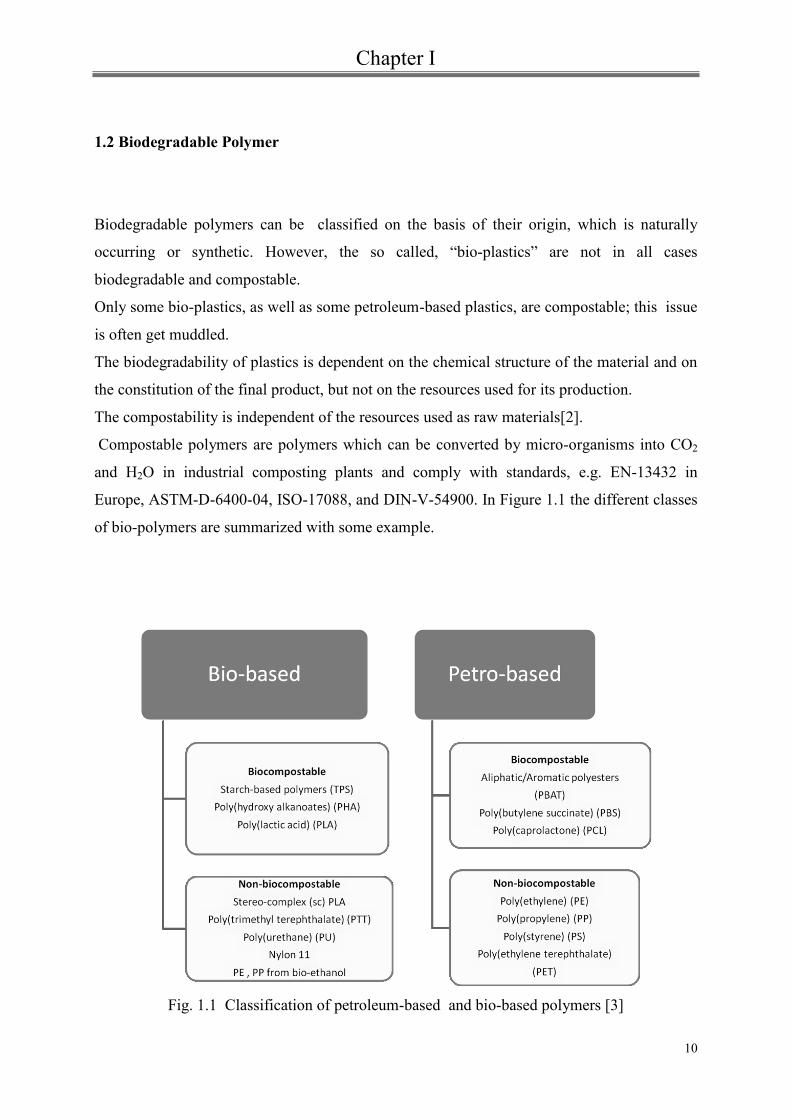
Compostable polymers are polymers which can be converted by micro-organisms into CO2
and H2O in industrial composting plants and comply with standards, e.g. EN-13432 in
Europe, ASTM-D-6400-04, ISO-17088, and DIN-V-54900. In Figure 1.1 the different classes
of bio-polymers are summarized with some example.
Fig. 1.1 Classification of petroleum-based and bio-based polymers [3]

Chapter I
11
In the short and medium term, the demand for bio-plastics may be appreciably enhanced if a
positive dialogue among industry and the social movements concerned with the sustainability
concept is established, emphasizing the benefits involved in the adoption of bio-plastic
products. Governments at local and national levels can also promote the use of bio-plastics by
passing legislation encompassing economic incentives to the adoption of bio-plastics in the
industrial supply chain, and at the same time enforcing restrictions to the trade of
environmental-unfriendly products[4]. However, some drawbacks to the expansion of the
bio-plastic could be posed by their high costs, narrow processability window, and mechanical
properties relatively inferior to those of other conventional polymers.
The improvements of these polymers are required in order to obtain more competitive
materials preserving the biodegradability.
Different approaches have been studied to enhance the final materials properties:
o Blends with other suitable biodegradable polymers
o Introduction into the host matrix of small amounts of nanoparticle fillers.
1.2.1 Biodegradable polymer blends
Biodegradable polymers can be classified according to their source [5]:
polymers from renewable resource such as the agro-polymers from agro-resources
(e.g., starch, cellulose),
polymers obtained by microbial production, e.g., the polyhydroxyalkanoates,
polymers chemically synthesized using monomers obtained from agro-resources, e.g.,
the poly(lactic acid),
polymers obtained by chemical synthesis from fossil resources.

Chapter I
12
Fig.1.2 Schematic representation of biodegradable polymers
Polymer blending is a technique that allows to modify the properties using a conventional
technology at low cost [6]. Polymer blends can be classified into several categories based on
their miscibility which can be distinguished by their phase morphology and changes in glass
transition temperatures.
Numerous biodegradable polymer blends have been developed in the last years. Today
several biodegradable polymers are in the market especially Polylactic acid (PLA), the PHA’s
and thermoplastic starch based polymers[7,8].
PLA has been blended with plasticisers and a remarkable number of polymers such as
poly(ε-caprolactone) (PCL) [9-12], polyhydroxy butyrate (PHB) [13,14], poly(butylene
succinate) (PBS) [15], soy-bean oil (PSO) 16].
Blends with PLA or PCL bring about an improvement of PHA’s processability [17-19] and
polyhydroxy butyrate-co-valerate (PHBV) copolymers that belong to PHAs’ family, was

Chapter I
13
modified by blending with many polymers such as poly vinyl chloride [20], poly(propylene
carbonate) [21], poly(L-lactic) acid [22], poly(ethylene succinate) [23], polyolefins [24], and
polycaprolactone [25].
TPS (thermoplastic starch) is used as a filler, lowering the price and enhancing the overall
biodegradation rate. A completely biocompostable blend is obtained by adding it to PLA or
PHBV[3]. Starch-based blends have been commercialized like Mater-Bi [26,27] (Novamont-
Italy) or Bioplast [28] (Biotec-Germany) and different published works have shown the
properties of TPS/PCL blends [27,29,30,31].
1.3. Nanocomposites
In contrast with traditional composites, where the reinforcements have dimensions in the
order of micron, nanocomposites represent a new class of materials to which fillers with at
least one of dimensions on the nano-scale are added. They have unique properties not shared
by the conventional composites as well as the added value to use low filler percentages
respect to composites ( up to 30-40 wt%), enabling easier processability.
The matrix/filler compatibility, the filler dispersion within the matrix and the aspect ratio (i.e.
surface to volume or length to thickness with platelets) are critical aspects to obtain
nanocomposite properties enhancement.
Advantages deriving from nanocomposites’ use may include decreased gas permeability
[32,33] and flammability [34], increased strength and heat resistance [35], high modulus
[36,37], and increased biodegradability of biodegradable polymers [38].
Three types of fillers can be defined according to how many dimensions are in the nanometric
scale:
1) three dimensional nanoparticles (pseudo-spherical), all dimensions are in the order of
nanometres,
2) bi dimensional nanoparticles (nanotubes or whiskers), with the third dimension larger
than nanometric one

Chapter I
14
3) mono dimensional (sheet-like) nanoparticles, only one dimension is in the order of
nanometres.
Today the market has focused its attention on nanoclay fillers[39].
The concept of polymer–clay nanocomposites (PCN) was developed in the late 1980s and
have received intense attention since the study published by the Toyota Central Research
Laboratories[40,41].
Several technologies are used for the preparation of PCN and the most common used are:
In-situ polymerization: filler and monomers are mixed to let the monomer enter into
clay’s layers, than polymerization reaction is promoted, allowing polymer to grow into
clay’s galleries. During the mixing step, the monomers spread in between the sheets of
the clay and they are attracted for the high polarity of the surfaces of clay platelets.
Then, the polymerization begins using heating, radiation, catalyst or organic
initiator[42-44].
Intercalation from solution: the nanoclay and and the polymer are dissolved in a polar
organic solvent that has to be able to solubilise the polymer and favor the clay
dispersion. Then the solvent evaporates or precipitates adding non miscible solvent
enabling layers to be reunited by entangling polymer macromolecules into them and
forming an ordered structure. However, this technique is environmentally unfriendly
and economically prohibitive[45,46].
Melt blending: clays and polymer are mixed in molten condition.
This process is of great interest for the industry because it is possible to use it with
conventional technologies as extrusion, which is a cheap and rapid technology.
Furthermore the use of harsh organic solvents is not necessary reducing
environmental impact and economic cost.
It is necessary to consider different parameters that can influence the latter process such as
shear devise, time residence, stress shear and organo-treatment of the clays. Moreover it is

Chapter I
15
worth noting that polymer-clay interaction mechanisms (miscibility between polymer and
clay, hydrogen bonding, electrostatic, coordination, etc.) depends on the polarity, molecular
weight, hydrophobicity, reactive groups, etc. of the polymer and clay mineral type [47].
1.4 Clay minerals
Clay minerals are part of the larger class of silicate minerals: the phyllosilicates. The
phyllosilicates are composed by tetrahedral and octahedral building units and they are also
known as layered silicates due to their stacked structure of 1-nm silicate sheets with a
variable basal distance [47]. The structure of tetrahedral sheet is made up of individual
tetrahedrons in which one silicon atom is surrounded by four oxygens. The arrangement is a
hexagonal pattern in which the basal oxygens are linked; while the apical oxygens take part in
the adjacent octahedral sheet and they point up/down [48].
FIG.1.3 Silica tetrahedron and structure of tetrahedral sheet[49].
The alumina octahedral crystal structure consists of one aluminum atom tied to six oxygens
and octahedral sheets are made up of individual octahedrons sharing edges composed of
oxygen and hydroxyl anion groups coordinated by cations as Al, Mg, Fe3+
and Fe2+
. These
octahedrons are arranged in a hexagonal pattern, too.

Chapter I
16
FIG.1.4 Alumina octahedron and structure of octahedral sheet[49].
There are two varieties of octahedral sheets: di-octahedral in which the cations are trivalent
(i.e. Al3+
) and the cation to oxygen ratio is 1:3 to maintain electric neutrality but one of the
cation sites is vacant. When cations in octahedral sheet are divalent (+2) (usually Mg or Fe+2
)
then a tri-octahedral sheet is formed. In this case the cation to oxygen ratio is 1:2 and every
lattice site is filled [50].
The classification of phyllosilicates is based on the number and the combination of
tetrahedral, di- and tri-octahedral sheets. This family of clay minerals can be divided in two
classes:
1:1 phyllosilicates - one silica tetrahedral sheet and one alumina octahedral sheet
combined to form a layer unit characterized by the fact that the apical oxygens of the
tetrahedral sheet are also part of the octahedral sheet (e.g. Kaolinite) (Fig. 1.5 A)

Chapter I
17
FIG. 1.5A Structure of 1:1 phyllosilicates [51]
2:1 phyllosilicates - two silica tetrahedral sheets with a central alumina octahedral
sheet (e.g. montmorillonite, saponite, etc.) (Fig.1.5 B)
The layered- silicates mainly used in nanocomposites belong to the latter family of
phillosilicates. The crystal structure is made up of two tetrahedral sheets of silica fused to an
edge-shaped octahedral sheet of alumina or magnesia. The length of each layered sheet ranges
from 30 nm to several micron and its thickness is about 1 nm. Layers stacking leads to a
regular Van der Waals gap between the platelets called the interlayer or the gallery. With the
exception of kaolinite, isomorphic substitutions is very common: a cation can be replaced by
ions of lower valence ( Si3+
in the tetrahedral sheet can be replaced by Al2+
, while Al2+
in the
octahedral sheet may be replaced by Li+, Mg2
+, Fe
2+, Fe
3+, Zn
2+, etc.). Isomorphic
substitutions, as well as the presence of vacancies, can induce a negative charged surface of
the clays layers. This negative charged surface is counterbalanced by alkali and alkaline earth
cations ( Na+,Ca
++. K
+) situated inside the galleries[42].

Chapter I
18
The inorganic cations located in the galleries lead to an increase of the hydrophilic character
of silicate surface and for this reason miscible with hydrophilic polymers such as
poly(ethylene oxide) (PEO) [52] or poly(vinyl alcohol) (PVA) [53].
FIG. 1.5 B Structure of 2:1 phyllosilicates [51]
Thus, in order to make silicates miscible with organophilic polymers, it’s required a chemical
modification of the hydrophilic silicate surface.

Chapter I
19
Table 1.1. Classification of clay minerals [54].
1.4.1 Modification of clays
The modification of the silicate surface to render layered silicates miscible with an
organophilic polymer matrix is necessary to improve their dispersion into the matrix so as a
nanocomposites can form. There are different procedures to modify the clays among which:
Ion-exchange with organic cations: small molecules can substitute the cations that are not
strongly bound to the clay surface. The use of primary, secondary, tertiary, and quaternary
alkylammonium or alkylphosphonium cations requires varied results; the surface energy of
the clay platelets decreases easing the penetration of polymers or monomers into the clay
galleries and they can provide functional groups that can react with the polymer matrix[42].

Chapter I
20
FIG. 1.6 Schematic representation of ion-exchange method
Ion-dipole interaction : The organic polar molecules can be absorbed by mineral clay by the
formation of a coordination bond between the exchangeable cation and the organic molecules
or by proton transfer from interlayer water to the organic molecules, or vice versa [55].
The partial negative charge of organic molecules allows the interaction with exchangeable
cations by the formation of ion-dipole bonds. Glycols[56] and amides[57] have also been used
as clays modifiers.
Silylation reaction: The grafting of silane onto clay surface [58] have been extensively
investigated. The strategy of silylation is based on creation of covalent bonds between an
organosilane and the hydroxyl groups located on the clay edge; via a condensation reaction
can form siloxane bonds Si-O-Si [59]. If a silanol is chosen with a functional group able to
react with the polymer, a covalent bond may be created between the clay filler and the
polymer matrix [60].
FIG. 1.7 Reaction between clay hydroxyl groups and organosilane

Chapter I
21
One of the main issues in preparing nanocomposites with good properties is the uniform
dispersion of the nanoparticles in the polymer matrix. Undoubtedly the possibility of
organically modifying clays has partly contributed to overcome this problem.
BibliographyI
22
[1] Knox, Andrew (February 2005). “An overview of incineration and EFW Technology
as applied to the management of municipal solid waste 9MSW”. Univeristy of western
Ontario. http://www.oneia.ca/files/EFW0
[2] Mareschal F., Biodegradable Plastics Views of APME (Association of Plastic
Manufactures in Europe) in E. Chiellini, R.Solaro eds. Biodegradable Polymers and
Plastic, Kluwer Academic/Plenum Publishers NY, pp 67-71, 2003.
[3] Piming Ma, Tailoring the properties of bio-based and biocompostable polymer
blends, 2011-Ph. D Thesis
[4] Antonio U. B. Queiroz and Fernanda P. Collares-Queiroz, Innovation and Industrial
Trends in Bioplastics, Journal of Macromolecular Science R _ , Part C: Polymer
Reviews, 49:65–78, 2009
[5] Averous, L., Boquillon, N. Carbohydrate Polymers, 56(2), 111, (2004).
[6] Long Yu, Katherine Dean, Lin Li. Progress in Polymer Science 31, 6, 576 ( 2006),.
[7] L. Avérous and E. Pollet (eds.), Environmental Silicate Nano-Biocomposites,Green
Energy and Technology, _ Springer-Verlag London 2012.
[8] http://www.polyone.com/enus/docs/Documents/Biomaterials%20Development%20in
%20the%20Polymer%20Industry.pdf
[9] M.E. Broz, D.L. VanderHart, N.R. Washburn.. Biomaterials 24, 4181, (2003)
[10] Takayama T., Todo M., Hideto T., and Arakawa K., Kobunshi Ronbunshu,
63,9, 626, (2006).
[11] Dell’Erba, R.; Groeninckx, G.; Maglio, G.; Malincolino, M.; Migliozzi, A.
Polymer, 42, 7831, (2001).
[12] Chen C.C. Biomaterials, 24 1167(2003)
[13] Yu, L.; Dean, K.; Li, L.. Progress in Polymer Science, 31, 576 (2006).
[14] Zhang, L.; Xiong, C.; Deng, X. Polymer, 37, 235 (1996).
[15] Shibata, M.; Inoue, Y.; Miyoshi, M. Polymer, 47, 3557 (2006).
[16] Robertson, M. L.; Chang, K.; Gramlich, W. M.; Hillmyer, M. A.
Macromolecules, 43,1807 ( 2010).
BibliographyI
23
[17] Avella, M.; Martuscelli, E.; RaimoCopolymers. Journal of Materials Science,
35, 523 (2000).
[18] Khemani, K.; Schmidt, H.; Hodson, S.K. U.S. Patent 7297394,2007.
[19] Noda, I.; Satkowski, M.M.; Dowrey, A.E.; Marcott, C. Macromolecular
Bioscience, 4, 269- (2004).
[20] A. Marcilla, J.C. Garcia-Quesada, and E. Gil, J. Appl. Polym. Sci. 110(4),
2102 (2008).
[21] J. Tao, C. Song, M. Cao, D. Hu, L. Liu, N. Liu, and S. Wang, Polym. Degrad.
Stab. 94(4), 575 (2009).
[22] .B.M.P. Ferreira, C.A.C. Zavaglia, and E.A.R. Duek, J. Appl. Polym. Sci.
86(11), 2898 (2002).
[23] L. Miao, Z. Qiu, W. Yang, and T. Ikehara, React. Funct. Polym. 68(2), 446
(2008).
[24] T. Sadik, V. Massardier, F. Becquart, and M. Taha, J. Appl. Polym. Sci.
(2012) DOI: 10.1002/app.37957.
[25] 15. M.J. Jenkins, Y. Cao, L. Howell, and G.A. Leeke, Polymer 48(21), 6304
(2007).
[26] Jasberg BK, Swanson CL, Shogren RL, Doane WM. J Polym Mater;9:163
(1992).
[27] Bastioli C, Cerrutti A, Guanella I, Romano GC, Tosin M. J Env Polym
Deg;3(2):81 (1995).
[28] Bastioli C. Polym Deg Stab;59:263 (1998).
[29] Amass W, Amass A, Tighe B. Polym Int;47:89 (1998).
[30] Pranamuda H, Tokiwa Y, Tanaka H. J Env Polym Deg;4(1):1 (1996).
[31] L. Averous, L. Moro, P. Dole, C. Fringant. Polymer 41 4157–4167 (2000).

BibliographyI
24
[32] Messersmith P.B, Giannelis E.P. J. Polym. Sci, Part A: Polym. Chem.33 1047-
57 (1995).
[33] Yano K., Usuki A., Okada A., Kurauchi T., Kamigaito O. J. Polym. Sci., Part
A: Polym. Chem. 31, 2493, (1993)
[34] Gilman J.W. Appl. Clay. Sci. 15 , 31, (1999)
[35] Giannelis E.P. Polymer . Appl. Organomet. Chem. 12,675, (1998)
[36] LeBaron P.C., Wang Z., Pinnavaia T.J. . Appl. Clay. Sci. 15, 11, (1999)
[37] Giannelis E.P. Polymer layered silicate nanocomposites. Adv. Mater. 8, 29,
(1996)
[38] Sinha Ray S., Yamada K., Okamoto M., Ueda K. Nano Lett. 2, 1093, (2002)
[39] Patent No.: US 7,888,419 B2, Feb.15,2011.
[40] A. Usuki; M. Kawasumi; Y. Kojima; A. Okada; T. Kurauchi; O. Kaminogato,
J. Mater. Res., , 8(5),1174, (1993)
[41] A. Usuki; Y. Kojima; M. Kawasumi; A. Okada; Y. Fukushima; T. Kurauchi;
O. Kaminogato, J. Mater. Res., , 8(1), 1185 (1993)
[42] Ray, S.; Okamoto, M. Progress in Polymer Science, 28, 1539 (2003).
[43] Lebaron, P. C.; Wang, Z.; Pinnavaia, T. J. Applied Clay Science, 15, 11 (1999)
[44] Alexandre, M.; Dubois, P. Materials Science and Engineering: A 28, 1,
(2000),
[45] Okamoto, M. Rapra Review Reports, 14, 1-40( 2003)
[46] Scott, M.A., Carrado, K.A. and Dutta, P.K. (eds).. Hand Book of Layered
Materials. (2004)
[47] Utracki, L. A.; Kamal, M. R. The Arabian Journal for Science and
Engineering, 27, 43 (2002)
[48] http://www.swac.umn.edu/classes/soil2125/doc/s11ch1.htm
[49] http://www.geol.umd.edu/~jmerck/geol342/lectures/07.html
[50] http://classes.colgate.edu/rapril/geol201/summaries/silicates/phyllo.htm
BibliographyI
25
[51] RE Grim, "Applied Clay Mineralogy. " McGraw-Hill Book Company, New
York, (1968).
[52] Aranda P, Ruiz-Hitzky E. Poly(ethylene oxide)-silicate intercalation materials.
Chem Mater; 4:1395 (1992).
[53] Greenland DJ. Adsorption of poly(vinyl alcohols) by montmorillonite. J
Colloid Sci;18:647, (1963)
[54] Bailey SW, chairman Summary of recommendations of AIPEA [Association
Internationale Pour l’Étude des Argiles] nomenclature committee on clay.
AmMineral, 65:1-7.(1980b)
http://www.minsocam.org/msa/collectors_corner/arc/nomenclaturecl1.htm.
[55] Yariv, S.; Cross, H., Organo-Clay Complexes and Interactions. In Marcel
Dekker, Inc: New York and Basel,; pp 1-101.( 2002)
[56] Beall, G.W., Goss, M.,. Appl. Clay Sci. 27, 179 (2004)
[57] Tahoun, S. A.; Mortland, M. M. Soil Science, 10, 314 (1966).
[58] N.N. Herrera, J.M. Letoffe, J.L. Putaux, L. David, E. Bourgeat-Lami,
Langmuir 20 1564. (2004)
[59] M. Ogawa, S. Okumoto, K. Kuroda,. Journ. Am. Chem. Soc. 120 ,7361. (1998)
[60] N.N. Herrera, J-L. Putaux, E. Bourgeat-Lami,. Progr. In Solid State Chem. 34
121,(2006)

Chapter II
Materials : Literature review

Chapter II
27
2. 1 Aliphatic copolyesters : Poly(hydroxyalkanoates) (PHAs)
2.1.1 Synthesis
Polyhydroxyalkanoates (PHAs) are synthesized through a fermentation process using
bacteria, which generate the polymer, typically copolymers, as an energy reserve within the
cell cytoplasm when the concentration of some nutrient, like nitrogen, phosphorous,
magnesium, is limited [1]. The microorganisms will then utilize these storage polymers as
carbon and energy source during conditions of starvation[2,3,4]. The fermenting step requires
from 30 to 48 hours. The cells are isolated through a drying process, and the PHAs are
usually recovered by a solvent extraction method using acetone or alcohols [5]. PHAs can be
produced either by fed-batch or continuous fermentation; it depends on the type of bacteria.
The mass production of PHAs is influenced by microorganism ability to utilize an
inexpensive carbon source, growth rate, polymer synthesis rate, and the maximum extent of
polymer accumulation[6]. The choose of bacteria and carbon source employed defines the
structure of the final PHA[1,7].
FIG.2.1 Microorganism cell containing PHAs granules
In 1926 Maurice Lemoigne discovered that anaerobic degradation of Bacillus megaterium led
to the excretion of poly-3-hydroxybutyrate (PHB) [8]. Ralstonia eutrophia (R. eutropha) is
used for synthesizing poly(3- hydroxybutyrate) and 3-hydroxybutyrate copolymers [1, 5, 9].
Using glucose and propionate as the carbon feed source with R. eutropha, poly(3-
hydroxybutyrate-co-3- hydroxyvalerate)(PHBV) is obtained with a concentration of the 3-
hydroxyvalerate that can be adjusted by varying the ratio of glucose to propionate in the
feedstock[9]. The increasingly use of E. coli to produce PHB- Poly(3-hydroxybutyrate) is

Chapter II
28
due to its ability to synthesize extremely high intracellular levels of PHB, being easy
genetically modifiable and its ability to use several inexpensive carbon sources. Moreover the
utilization of mutants to metabolically engineer strains that produce P(3HB-co-3HV)
copolymers [10,11]. Poly(3-hydroxybutyrate) (3HB) is the typical backbone of PHA
copolymers[1, 8, 12, 13] and, depending on the number of methylene group in the backbone
(m in figure 2.2) and the length of the side chain in the structure (R in figure 2.2), several
PHAs can be formed.
FIG 2.2 General structure of polyhydroxyalkanoates [14].
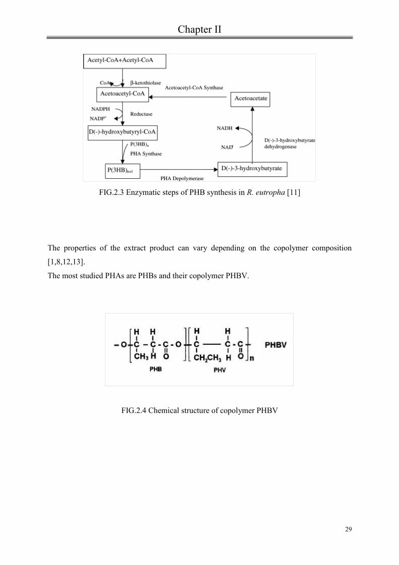
There are four main gene classes involved in the synthesis of PHAs[6, 15].
The most studied pathway is the synthesis of PHB using the bacterium Ralstonia eutropha in
which the condensation of two acetyl-CoA molecules by a beta-ketothiolase produces
acetoacetyl-CoA. NADPH-dependent acetoacetyl- CoA reductase then carries out its
conversion to 3-hydroxybutyryl-CoA. The final step is the polymerization by PHB
synthase[6].
The remaining pathways differ from the first for the catalytic functions carried out by the
other classes of enzymes[16].
Chapter II
29
FIG.2.3 Enzymatic steps of PHB synthesis in R. eutropha [11]
The properties of the extract product can vary depending on the copolymer composition
[1,8,12,13].
The most studied PHAs are PHBs and their copolymer PHBV.
FIG.2.4 Chemical structure of copolymer PHBV

Chapter II
30
2.1.2 PHBV properties
Pure poly(3HB) is a stiff polymer due to its high crystallinity (a 60-80%)[13,17]; the low rate
of crystallization related to the low heterogeneous nucleation density entails the growth of
large spherulites that form inter-spherulitic cracks and cause brittle failure[17,18].
In order to improve the toughness of PHB, poly-(3-hydroxyvalerate) (HV) or (PHV) units are
incorporated into PHB. A structural characteristic of PHBV is the isodimorphism. This resins
display a melting temperature minimum for PHV content of 30 mol% and co-crystallization
of the two monomer units in either of the homopolymer crystal lattices of PHB and PHV,
depending on whether the (R)-PHV composition is above or below 40 mol%[6, 19].
The crystallinity of PHBV is about the same of PHB omo-polymer however the melting
temperature is lower depending on the HV content[20] . The crystallinity and mechanical
properties of PHBV can change with the variation of the percentage ratio of the respective
monomers[21].
The rate of crystallization of PHA decreases with increasing structural complexity of the
polymer. The bulky side groups in 3HV prevents crystallization due to steric effects[22].
Increasing HV content the melt stability is improved using lower processing temperatures[6,
23, 24]. Poly(3HB-co-3HV) has a good O2, CO2, and water vapor barrier, and it is suitable for
some food packaging applications and containers for cosmetic products [5, 25].
The tensile strength of poly(3HB-co-3HV), on varying HV content, is about 20-40 MPa and
the modulus decreases to 800- 2000 MPa with an increasing of elongation at break up to 20-
30%[18, 26].
In table 2.1 some typical properties of PHBV with different HV content are shown.
2.1.3 PHBV composites
After the industrial production of PHBV under the trade name BIOPOL by Zeneca Bio
Product for this polymer there was an attracting growing interest from researchers[27]. Choi
and his group [28] showed results about PHBV/ Cloisite 30 B nanocomposites, prepared
through a melt intercalation method. An intercalated structure was verified by XRD and
TEM analyses. The temperature and rate of crystallization of PHBV increased with the
Chapter II
31
organo-clay acting as nucleating agent. Moreover, the nanocomposites showed significant
increases in tensile strength and thermal stability[28]. The nucleation effect of the
organophilic montmorillonite (OMMT) was studied by Chen et al.[29].They showed that
OMMT acted as a nucleating agent in the PHBV matrix but the nucleation and the overall
crystallization rate decreased with the increase of clay content.
Wang and his co-workers[30] investigated the properties and the biodegradability of
PHBV/OMMT nanocomposites.
They found that the biodegradability of PHBV/OMMT nanocomposites in soil suspension
decreased with an increase in the amount of OMMT.
A comparison of morphology , thermal and mechanical properties of PHBV nanocomposites
using two different types of silicates, organo-modified montmorillonite(C30B) and Halloysite
nanotubes (HNTs), was evaluated in the work of Carli et al.[31].
Although the researches principally concern fillers with lamellar or layered structure for their
availability and versatility, adding of nano-particles in PHBV like zinc oxide [32, 33],
attapulgite [34], hydroxyapatite [35], fumed silica [36] , calcium phosphate [37] or titanium
dioxide[38] have also been reported. The effect of carbon nanotubes was analyzed by Lai et
al.[39] and to develop completely biodegradable composites several types of natural fibers
were utilized such as bamboo pulp[40], short abaca[41], jute [42] and kenaf fibers[43].
2.2 Aliphatic-Aromatic copolyesters: Poly(butylene adipate-co-terephthalate) (PBAT)
The most important factors for the biodegradable plastics for commercial uses are price,
performance and use of existing plant. In this regard, among the commercially available
biodegradable polymers, synthetic aliphatic and aromatic biopolyesters such as poly(butylene
adipate-co-terephthalate) (PBAT) show good thermal and mechanical properties with the
added advantage of biocompatibility and biodegradability[44].
The introduction of terephthalate units into the main chains of aliphatic polyesters can
mprove the physical as well as biodegradable properties of the polymer[45].
PBAT, was commercialized by BASF under the trade name of Ecoflex® F BX 7011. It is an
aliphatic-aromatic copolyester based on terephthalic acid, adipic acid, 1,4- butanediol and
modular units as the statistical copolyester units, including 1,4-butanediol and the dicarbonic

Chapter II
32
acids, adipic acid and terephthalic acid, are linked.
These modular systems involve the incorporation of hydrophilic components of monomers
with branching, leading to chain-lengthening, and thereby increasing the molecular weight to
yield tailor-made products with totally different material properties[46].
FIG.2.5 Chemical structure of PBAT[47].
Ecoflex® doesn’t contain additives for decomposition and doesn’t produce any negative
consequences for environmental risk (ecotoxicity) if introduced into composting
processes[48].
2.2.1 PBAT composites
Up to this time only few articles regarding PBAT/ clay nanocomposites have been published
Someya et al.[49,50] obtained certain level of clay intercalation and exfoliation in some
compositions of PBAT- organically modified montmorillonites (OMMT) nanocomposites.
Chivrac et al. [51, 52] used various commercial organoclays as fillers in PBAT matrix by
different preparation processes (i.e., solvent or melt intercalation). The higher intercalation
degrees were obtained by solvent intercalation. The thermal and mechanical properties of
composites system were also investigated.
Mohanty and Nayak [53] investigated the morphology and the properties of PBAT reinforced
with different types of organoclays such as Cloisite30B (C30B), Cloisite20A (C20A),
Bentonite (B109). Furthermore, they found an additional improvement of mechanical
properties via functionalization of PBAT matrix upon grafting with maleic anhydride (MA) .

Chapter II
33
An interesting study of soy protein concentrate (SPC) blended with poly(butylene adipate-co-
terephthalate) (PBAT) was performed by Chen [58]. Using maleic anhydride grafted PBAT
an overall improvement of the mechanical properties and the formation of percolated SPC
network structure at high SPC concentrations was observed.
Recently, Fukushima and his co-workers[47] tried to improve the mechanical and thermal
properties of PBAT by adding different types of nanoparticles, such as montmorillonites,
hectorites and sepiolites, into the biodegradable matrix. They concluded that the best thermo-
mechanical and physical properties of all nanocomposites studied were achieved with the
addition of needle like sepiolite .
There is a growing interest in the field of biodegradable composites (biocomposites) ,
obtained by the combination of biodegradable polymers and biodegradable fillers (e.g.,
lignocellulosic fillers). Several studies are based on biodegradable polyesters matrices[54].
For example composites of PBAT with natural fiber have been studied.
Wu[55] in his work improved noticeably the mechanical properties of the neat polymer
making composites with sisal fibers. The grafting of acrylic acid onto polymer matrix was
carried out in order to enhance the compatibility between the two components.
Avèrous and F. Le Digabel [56] studied thermal and mechanical properties of biocomposites
made of Poly(butylene adipate- co-terephthalate) (PBAT) and lignocellulosic fillers (LCF).
The fibers increased the thermal degradation temperature of the matrix and, although the
cristallinity didn’t change, the fillers induced a nucleating effect. These biocomposites
showed good mechanical properties. The addition of oil palm empty fruit bunch (EFB) fibers,
chemical treated with succinic anhydride, in PBAT matrix improved thermal stability ,
tensile and flexural properties[57].

Chapter II
34
2.3 Halloysite nanotubes
2.3.1 Halloysite structure
Deposits of Halloysite are in several countries but most of which contain other clays like
Kaolinite and some impurities. High purity deposits can be found in Utah (USA), in the
Dragon mine, and in New Zealand.
Halloysite is a two-layered (1:1) natural aluminosilicate clay, chemically similar to kaolin,
and with a stoichiometry Al2(OH)4Si2O5•nH2O where n is 0 or 2 (Figure 2.6) depending on
the two different polymorphs in which Halloysite can occur : the hydrated form (with
interlayer spacing of 10 Å) and the anhydrous form (with interlayer spacing of 7 Å). The
intercalated water is weakly bound and can be readily and irreversibly removed[59].
Aluminosilicates can occur in agglomerates, spheroids, sheets, or in hollow, tubular shapes.
Halloysites exhib a predominantly tubular morphology, but other shapes have been reported
(scroll, glomerular or ‘onion-like’, platy)[59].
FIG. 2.6 Crystalline structure of Halloysite (a) and detail of nanotube(b) [60].
Halloysites have two different basal faces. The first one consist of a tetrahedral silicate
surface Si-O-Si while the other basal surface has a di-octahedral layer (Al(OH)3) in which

Chapter II
35
only 2/3 of the existing octahedral sheet are filled by aluminium[61].
In Halloysites siloxane groups are bonded via only one oxygen atom to gibbsite octahedral
rings at the outer part (figure 2.7), and the apical oxygen of tetrahedra becomes the vertices of
octahedral[62].
According to Bates et al.[63] the cylindrical shape of clay is the effect of strain caused by
mismatch in the two alignment of the tetrahedral sheet of silica bonded to the octahedral sheet
of alumina.
The charge characterists of Halloysite depend on pH value[64]. The clay presents negative
charge at pH higher than 3 owing to the deprotonation of water and hydroxyl groups bound to
aluminum and silicon at the edges.
The edges are considered to be positively charged at low pH, neutral at the isoeletric point (at
around pH 3), and negatively charged at higher pH[65]. Halloysites are characterized by
structural imperfections like substitutions of the Al3+
by Fe3+
in octahedral layer and Si4+
in
the tetrahedral sheet is often replaced by Al3+
[59, 66]. These substitutions entail changes of
the microstructure and the dimensions of tetrahedrons and octahedrons[66].
FIG. 2.7 Bonding of silicon atom to di-octahedral ring in Halloysite (7 Å)[61].
Dimensions of Halloysite particles vary from 50 to 70 nm in external diameter, ca. 15 nm
diameter lumen and 1-1.5 μm length[67].
The Young’s modulus is between 230-340 GPa, depending on the orientation of overlapped
nanotubes (armchair, zig-zag) and the number of layer defects compared to single-walled

Chapter II
36
ones[68].
Recently, Halloysite nanotubes, typically used in the manufacture of high quality ceramic
white-ware, have received much attention. In fact, on one side, they have the potential to
provide cheap alternatives to the expensive carbon nanotubes whereas, on the other hand,
given their chemical similarity to lamellar clays as montmorillonites, they have the possibility
to be further intercalated by chemical and/or physical ways[69].
These nanotubes have a wide range of applications considering interesting structure and
properties such as widespread availability, large aspect ratio, high stiffness and their
biocompatibility was demonstrated by Vergaro et al. (the nanotubes are not toxic for the
cells)[70].
Their utilization as nanoscale container for the encapsulation of biologically active molecules
(e.g., biocides, enzymes, and drugs), as a support for immobilization of catalyst molecules,
controlled release, bioimplants, and for protective coating (e.g., anticorrosion or antimolding)
has been also investigated[59, 70,71,72].
2.3.2 Halloysite/ polymer composites
Halloysite can be employed as nanofiller into polymer matrices to improve mechanical
properties or fire performance [61].
Thermal stability and flame retardant effect of the Polypropylene/HNTs nanocomposites were
investigated by Du et al.[73]. During the initial degradation stages of composite formulations,
the degradations products, being entrapped into the lumen of HNTs, are delayed to diffuse
and consequently an increased thermal stability is recorded.
Ye et al. [74] demonstrated that blending epoxies with an appropriate amount of HNTs could
significantly increase impact strength without sacrificing flexural modulus, strength, and
thermal stability.
Marney et al. [75] reported that nylon 6-halloysite composites show an improved fire
behavior by a decrease of some fire properties parameters such as the peak of heat release rate
(PHRR), the total heat released (THR), and the peak of mass loss rate (PMLR) with respect to
the neat matrix by increasing the filler content. Moreover they reported about a thermal

Chapter II
37
insulation barrier that is developed at the surface of the composite during the burning acting
as a flame retardant but without stopping the fire front.
Halloysite and ethylene propylene diene monomer (EDPM) nanocomposites were prepared by
Ismail and his co-workers [76]. The increases in tensile strength, stiffness and ductility of
EPDM/HNT nanocomposites were attributed to interfacial and inter-tubular interactions
between HNTs and EPDM, and edge-to-edge and face-to-edge interactions between HNTs
(zig-zag structure)[76].
Halloysites can also influence crystallization process of polypropylene as reported by Ning et
al. [77]. They found that HNTs act as nucleating agents and enhance the overall
crystallization rate. The HNTs also act as a nucleation point in isotactic polypropylene for
both α-PP and β-iPP, depending on the temperature and the processing conditions[78].
A study about polymorphism of PA6/HNTs nanocomposites was conducted by Guo et al
.[79].
2.3.3 Modification of Halloysite nanotubes
In order to improve compatibility between clay nanotubes and polimer matrix, Halloysites
have been functionalized with different silanes.
As described by Guo et al.[80] mechanical properties and heat distortion temperature were
improved with addition of functionalized HNTs into PA6 matrix. Halloysites were modified
with 3-(trimethoxysilyl)propyl methacrylate(MPS).
Pasbakhash et al. modified HNTs with γ-methacryloxypropyl trimethoxysilane (MPS) to
improve their dispersion in ethylene diene monomer (EPDM). The obtained nanocomposites
showed tensile strength and tensile modulus at 100% elongation higher than those of
EPDM/unmodified HNTs[81].
Halloysites modified with γ-glycidoxypropyltrimethoxy silane were incorporated into epoxy
resin; the obtained nanocomposites exhibited improved flexural strength due to uniform
dispersion of the nanotubes as TEM pointed out[82] .

Chapter II
38
A detailed study on modification of Halloysite clay nanotubes with γ-
aminopropyltriethoxysilane (APTES) was done by Yuan et al.[83].
Recently, Phenylphosphonic acid (PPA) was used to unroll HNTs[84]. The unfolded and
intercalated Halloysite increased fracture toughness of cured epoxies.

Bibliography
39
[1] Braunegg, G.; Lefebvre, G.; Genser, K.F. Journal of Biotechnology, 65, 127 (1998)
[2] Anderson AJ, Dawes EA. Microbiol Rev. 54(4):450 (1990)
[3] Bernd H. A. REHM. Biochem. J. 376, 15 (2003)
[4] Verlinden RA, Hill DJ, Kenward MA, Williams CD, Radecka I. J Appl Microbiol.
102, 6,:1437 (2007).
[5] Wolf, O. (Ed). Techno-economic Feasibility of Large-scale Production of Bio-based
Polymers in Europe. Seville: Institute for Prospective Technological Studies: Technical
Report Series, (2005).
[6] Khanna, S., Srivastava, A.K. Proc Biochem. 40, 607 (2005)..
[7] D’Haene P.;Remsen E.E.; Asrar, J. Macromolecules, , 32, 5229 (1999).
[8] Lemoigne, M. Bulletin de la Societe de Chimie Biologique, 8, 770 (1926).
[9] Holmes, P.A. Physics in Technology, 16, 32 (1985)
[10] Fidler, S., Dennis, D. FEMS Microbiol Rev. 103, 231 (1992).
[11] Hahn, S.K., Chang, Y.K., Lee, S.Y Appl Environ Microbiol. 61, 34. (1995).
[12] Noda, I.; Green, P.R.; Satkowski, M.M.; Schectman, L.A. Biomacromolecules, 6, 580,
(2005)
[13] Philip, S.; Keshavarz, T.; Roy, I. Journal of Chemical Technology and Biotechnology,
82, 233 (2007)
[14] Nicolas Jacquel, Chi-Wei Lo,Yu-Hong Wei,Ho-Shing Wu,Shaw S. Wang;
Biochemical Engineering Journal, 39, 1, 15 (2008).
[15] Aneja, KK. Ashby, RD. Solaiman, DKY. Biotechnol Lett ; 31: 1601 (2009)
[16] Davis, R. Anilkumar, PK. Chandrashekar, A. Shamala, TR. Antonie Van
Leeuwenhoek ; 94: 207 (2008).

Bibliography
40
[17] Barham, P.J. and Keller, A. Journal of Polymer Science, , 24, 69 (1986)
[18] El-Hadi, A.; Schnabel, R.; Straube, E.; Muller, G.; Henning, S.. Polymer Testing, , 21,
665 (2002).
[19] Sudesh, K., Abe, H., Doi, Y. Prog Polym Sci. 25, 1503 (2000).
[20] Nair, L. S., and Laurencin, C. T. Progress in Polymer Science, 32(8-9).762 (2007).
[21] Sabir, M. I., Xu, X., and Li, L, Journal of Materials Science, 44(21). 5713 (2009)
[22] Kunioka, M.; Tamaki, A.; Doi, Y.. Macromolecules, 22, 694 ( 1989)
[23] Ferreira, B.M.P., Zavaglia, C.A.C., Duek, E.A.RJ Appl Polym Sci. 86, 2898 (2002)
[24] Ramkumar, D.H.D., Bhattacharya. M. Polym Eng Sci. 38(9), 1426 (1998).
[25] Miguel, O.; Fernandez-Berridi, M.J.; Iruin, J.J. Journal of Applied Polymer Science, ,
64, 1849 (1997)
[26] Avella, M.; Martuscelli, E.; Raimo, M. Review:. Journal of Materials Science, 35, 523
(2000).
[27] Koning D, Can G. J Microbiol;41;303 (1995)
[28] W. M. Choi, T. W. Kim, O. O. Park, Y. K. Chang, and J. W. Lee, J. Appl. Polym.
Sci., 90, 525 (2003).
[29] Chen, G. X., Hao, G. J., Guo, T. Y., Song, M. D., Zhang, B. H. Journal of Applied
Polymer Science, 93(2), 655 (2004).
[30] Wang, S., Song, C., Chen, G., Guo, T., Liu, J., Zhang, B., Takeuchi, S. Polymer
Degradation and Stability, 87(1), 69 (2005)
[31] Larissa N. Carli; Janaina S. Crespo; Raquel S. Mauler Composites Part A 42 (11),
1601 (2011).
[32] Yu W., Lan C-H., Wang S-J., Fang P-F., Sun Y-M.: Polymer, 51, 2403 (2010).
[33] Naphade R., Jog J. Fibers and Polymers, 13, 692 (2012).
[34] Thiré R. M. S. M., Arruda L. C., Barreto L. S.: Materials Research, 14, 340 (2011).
Bibliography
41
[35] Jack K. S., Velayudhan S., Luckman P., Trau M., Grøndahl L., Cooper-White J. Acta
Biomaterialia, 5, 2657 (2009).
[36] Ma P. M., Wang R. Y., Wang S. F., Zhang Y., Zhang Y. X., Hristova D. Journal of
Applied Polymer Science, 108, 1770 (2008).
[37] Duan B., Wang M., Zhou W. Y., Cheung W. L. Applied Surface Science, 255, 529
(2008).
[38] Buzarovska, A., Grozdanov, A., Avella, M., Gentile, G. and Errico, M., Journal of
Applied Polymer Science, 114: 3118 (2009)
[39] Lai M., Li J., Yang J., Liu J., Tong X., Cheng H.Polymer International, 53, 1479
(2004).
[40] Jiang L., Huang J., Qian J., Chen F., Zhang J., Wolcott M. P., Zhu Y.Journal of
Polymers and the Environment, 16, 83 (2008).
[41] Shibata, M., Takachiyo, K.-I., Ozawa, K., Yosomiya, R. and Takeishi, H., J. Appl.
Polym. Sci., 85: 129 (2002)
[42] Bledzki A. K., Jaszkiewicz A. Composites Science and Technology, 70, 1687 (2010).
[43] Avella M., Gaceva G-B., Buzõarovska A., Errico M. E., Gentile G., Grozdanov A.
Journal of Applied Polymer Science, 104, 3192 (2007).
[44] F. Li, X. Xu, J. Yu, A. Cao, Polym. Degrad. Stab. 92 1053 (2007)
[45] Zhihua G, Kazuhiro K, Motonori Y, Hideki A, Yoshiharu D. Polymer Degradation
and Stability);83:289, (2004)
[46] MSc. Motonori Yamamoto, Dr. Uwe Witt, DI. Gabriel Skupin, Dr. Dieter Beimborn,
Dr. Rolf-Joachim Müller. Biodegradable Aliphatic- Aromatic Polyesters: ™Ecoflex.
[47] Kikku Fukushima, Meng-Hsiu Wu, Sergio Bocchini, Amaliya Rasyida, Ming-Chien
Yang. Materials Science and Engineering:, C32 (6):1331,( 2012).
[48] Witt, U.; Einig, T.; Yamamoto, M.; Kleeberg, I.; Deckwer, W.D.; Muller, R.J..
Chemosphere, 44 (2): 289 (2001).
[49] Y. Someya, Y. Sugahara, M. Shibata, J. Appl. Polym. Sci. 95 386 (2005)
[50] Y. Someya, T. Nakazato, N. Teramoto, M. Shibata, J. Appl. Polym. Sci. 91 1463
(2004)

Bibliography
42
[51] F. Chivrac, Z. Kadlecova, E. Pollet, L. Averous, J. Polym. Environ. 14 393 (2006)
[52] F. Chivrac, E. Pollet, L. Averous, J. Polym. Sci. Polym. Phys. 45 1503 (2007).
[53] Smita Mohanty, Sanjay Kumar Nayak. International Journal of Plastics Technology,
14 (2) , 192 (2010)
[54] Mohanty, A. K., Misra, M., & Hinrichsen, G. Macromolecular Materials and
Engineering . 1, 276. (2000)
[55] Chin-San Wu Process, Characterization and Biodegradability of Aliphatic Aromatic
Polyester/Sisal Fiber Composites. Journal of Polymers & the Environment; 19(3) , 706.
(2011)
[56] L. Avèrous, F. Le Digabel. Carbohydrate Polymers, 66 (4), 480 (2006).
[57] Siyamak S, Ibrahim NA, Abdolmohammadi S, Yunus WM, Rahman MZ;
Biocomposites. Int J Mol Sci. ;13(2):1327 (2012).
[58] Feng Chen, Jinwen Zhang, . Polymer 51( 8), 1812 (2010).
[59] Joussein, E.; Petit, S.; Churchman, J.; Theng, B.; Righi, D.; Delvaux, B, 40, 383
( 2005)
[60] Yuan, P.; Southon, P. D.; Liu, Z.; Green, M.; Hook, J. M.; Antill, S. J.; Kepert, C. J.,
Journal of Physical Chemistry C, 112 (40), 15742 (2008).
[61] Deepak Rawtani and Y.K. Agrawal.. Rev.Adv. Mater. Sci. 30 282 (2012)
[62] Hélio A. Duarte, Maicon P. Lourenço, Thomas Heine and Luciana Guimarães:.
Stability, Structure and Properties available at www.intechopen.com
[63] Bates, T.F., Hildebrand, F.A. & Swineford, A. American Mineralogist, 35, 463.
(1950a).
[64] Theng, B.K.G., Russell, M., Churchman, G.J. & Parfitt, R.L. Clays and Clay Minerals,
30, 143. (1982)
[65] Braggs, B.; Fornasiero, D.; Ralston, J.; Stsmart, R. Clays Clay Min., 42, 123 (1994).
[66] Balbir Singh Why does Halloysite roll?- A new Model. Clays and Clay Minerals, 44
(2), 191 (1996). .
[67] Yin-Feng Shi, Zhong Tian, Yang Zhang, He-Bai Shen and Neng-Qin Jia. Nanoscale
Research Letters, 6:608 (2011)

Bibliography
43
[68] Guimarães, L.; Enyashin, A. N.; Seifert, G.; Duarte, H. A. Journal of Physical
Chemistry C, 114 (26), 11358 (2010)
[69] H. Noro, Hexagonal platy Halloysite in a n altered tuff bed, Komaki City, Aichi
Prefecture , Central Japan Clay Miner. (1986) 21, 401
[70] Viviana Vergaro, Elshad Abdullayev, Yuri M. Lvov, Andre Zeitoun, Roberto
Cingolani, Ross Rinaldi, and Stefano Leporatti*, Biomacromolecules, 11, 820. (2010)
[71] Price RR, Gaber BP, Lvov Y: J Microencapsulation, 18:713 (2001).
[72] Abdullayev E, Price R, Shchukin D, Lvov Y. Appl Mater Interfaces, 1:1437 (2009).
[73] Mingliang Du, Baochun Guo , Demin Jia. European Polymer Journal 42 (6): 1362.
(2006)
[74] Y. Ye, H. Chen, J.S. Wu, and L. Ye, Polymer 48(21): 6426 (2007).
[75] Marney, D. C. O., Yang, W., Russell, L. J., Shen, S. Z., Nguyen, T., Yuan, Q., Varley,
R. and Li, S. Polym. Adv. Technol, 23: 1564.(2012).
[76] Ismail H., Pasbakhsh P., Fauzi M. N. A., Abu Bakar A.: Polymer Testing,. 27, 841.
(2008)
[77] Nan-ying Ning, Qin-jian Yin, Feng Luo, Qin Zhang, Rongni Du, Qiang Fu, Polymer
.48 ( 25): 7374 (2007).
[78] Liu, M.; Guo, B.; Du, M.; Chen, F.; Jia, D.Polymer, 50 (13):3022 (2009).
[79] Baochun Guo, Quanliang Zou, Yanda Lei, Mingliang Du, Mingxian Liu, Demin Jia,
Thermochimica Acta, 484, 1–2( 20): 48 (2009)
[80] Baochun Guo, Quanliang Zou, Yanda Lei and Demin Jia Polymer Journal,41 : 835.
(2009)
[81] Pooria Pasbakhsh, H Ismail, M N Ahmad Fauzi, A Abu Bakar. Applied Clay Science
48 (3): 405 (2010).
[82] Liu, M.; Guo, B.; Du, M.; Lei, Y.; Jia, D. Journal of Polymer Research, 15 (3): 205.
(2007)

Bibliography
44
[83] Peng Yuan, Peter D. Southon, Zongwen Liu, Malcolm E. R. Green, James M. Hook,
Sarah J. Antill and Cameron J. Kepert. J. Phys. Chem. C, , 112 (40):15742 (2008).
[84] Tang, Y.; Deng, S.; Ye, L.; Yang, C.; Yuan, Q.; Zhang, J.; Zhao, C. Composites Part
A: Applied Science and Manufacturing, 42 (4):345.(2011)

45
Chapter III
Film blowing process

Chapter III
46
3.1 The process
The blown film extrusion (film blowing) is an important industrial process to manufacture
thin and biaxially oriented polymeric films.
This process consists in extruding a polymer melt from an annular die and a biaxial
orientation is achieved by continuously inflating it and axial drawing to form a thin tubular
product. The equipment is provided with air jets to cool down the bubble. Figure 3.1 shows a
scheme of the film blowing process.
FIG. 3.1 Schematic of film blowing process[1].
More in details, polymer melt is extruded through an annular slit die, usually vertically, to
form a thin walled tube. The inflation of bubble is actuated by introducing air into the bubble
through a hole in the centre of the die. The tube then is pulled upwards, continually cooling,
towards the nip rollers which seal it to create what is known as a ' lay-flat' tube of film.
In the molten state the film is stretched in two directions.
When air is blown into the tube by the orifice in the annular die the film is being stretched in

Chapter III
47
the radial (transverse) direction, while the elongation along the axial (machine) direction is
achieved by controlling the velocity of the nip rollers and the mass flow rate at the die. These
two stretchings occur simultaneously and are controlled by changing the volume of air inside
the bubble and by altering the haul off speed.
Extension of the melt in both the radial and axial direction stops at the “freeze line ” (frost
line) due to the cooling air which is blown outside the bubble and determine the
crystallization of the melt. This is not a sharp line but a narrow zone over which solidification
occurs. In fact, the solidification occurs first at the cooled surface, at the melt-solid interface,
and then moves away from this surface through the thickness of the film. The height of the
freeze line can be controlled through the air flow rate and negligible deformation occurs
beyond the freeze line in most process[2, 3].
The main advantages in using this process are the following:
Regulation of film width and thickness by control of the volume of air in the bubble, the
output of the extruder and the speed of the haul -off
Eliminate end effects such as edge bead trim and non uniform temperature that can result
from flat die film extrusion
Very high productivity
Permits the combination of a number of different materials and properties
Blown films can be used either in tube form (e.g. for plastic bags and sacks) or the tube can
be slit to form a sheet. Typical applications include industrial packaging (e.g. shrink film,
stretch film, bag film or container liners), consumer packaging (e.g. packaging film for frozen
products, shrink film for transport, food wrap film, packaging bags, or form, fill and seal
packaging film), laminating film (e.g. laminating of aluminium or paper used for packaging
for example milk or coffee), barrier film (e.g. film made of raw materials such as polyamides
and EVOH acting as an aroma or oxygen barrier used for packaging food, e. g. cold meats and
cheese), films for the packaging of medical products, agricultural films (e.g. greenhouse film,
crop forcing film, silage film, silage stretch films.
This process is used extensively with polyesters and polyolefins. These-materials do not get
together, so a multi -layer film would delaminate. To overcome this, small layers of special

Chapter III
48
adhesive resins, best known as “tie layers”, are used in between.
The final film dimensions are determined by a number of process variables: the “blow up
ratio” (BUR), which is a ratio of the bubble radius a the freeze line to the radius of the die,
and the machine direction draw down ratio (DDR), which is the ratio of the velocity at the nip
rollers to the velocity of the polymer melt exiting the die.
Typically, the blow up ratio ranges between 1,5 and 4. The solidified film is flattened into a
double-layered sheet by the nip rollers forming an almost airtight seal at the top of the bubble.
After the flat film is reeled up under constant tension either as tubular film or after slitting
into sheet film. The width of the flattened tube is called the “layflat width” and this is equal to
p times the final bubble radius.
Rheological properties play a fundamental role in film blowing. They govern the shape and
the stability of the bubble and the onset of sharkskin (surface roughness). Because of the
complexity of the involved flows, it is generally impossible to establish simple quantitative
correlations between these phenomena and easy- measured rheological properties.
However, an understanding of how variations in the rheological behavior of melts can affect
the process and the properties of blown films is essential to achieve optimum results from this
process.
The objective of the film blowing process is to produce a thin film having a uniform gauge
and good optical and mechanical properties. Since the film is quite thin, it is especially
important to avoid the presence in the extrudate of unmelted material, gels or foreign matter,
as these will be readily visible in the final product. In order to achieve good mechanical
properties it is often advantageous, particularly in the case of packaging films, to have
molecular orientation in the film that is as much as possible “balanced” in the machine and
transverse directions.
Ultimate film properties are controlled by molecular orientation and stress induced
crystallization[4].
A stable bubble in the film blowing process is a requirement for the continuous operation of
the process and the production of an acceptable film [5]. In general there are three forms of
instabilities or combinations of these reported in literature:
1. Axisymmetric periodic variations of the bubble diameter, known as bubble instability (BI).
2. Helical motions of the bubble, described as helical instability (HI).
3. Variations in the position of the frost line height (FLHI).

Chapter III
49
BI and HI have been reported by a number of researchers [6–10], however, FLHI was only
reported by Ghaneh-Fard et al. [6,10], after previous authors were using the term “meta
stable” [3] which was misleading for time -dependent oscillations in FLH. Results on bubble
stability have generally been qualitative until recently when Sweeney et al. [11] utilized a
video analysis system as an effective non-contact, real time device for quantifying instabilities
during film blowing. Sweeney and his co-workers al. [11] first proposed the diameter range
(Dr) concept for measuring the degree of helical instability.
The average diameter, D, and the degree of helical instability (DHI) are then derived from the
following equations:
D = P1 - Pr (3.1.1)
Dmax = Pl ,max • Pr ,min, (3.1.2)
Dmin = Pl ,min • Pr ,max, (3.1.3)
Dr = Dmax • Dmin, (3.1.4)
DHI =
100 (3.1.5)
where D is the average diameter of the bubble and P is the average distance of the bubble
from a reference line.
The subscript r denotes the distance of the right bubble edge and l the distance of the left
bubble edge from the reference line. The bubble was defined as stable if the DHI was less
than 20%, partially helically stable if the DHI was between 20 and 40% and helically unstable
if the DHI was greater than 40%.
The analysis of bubble stability in film blowing has largely focused on PEs (HDPE, LLDPE
and LDPE), mainly due to their superior melt strength in comparison to other polymers such
as PP. Only recently have been reported results on the bubble stability of PP [10]. Ghaneh-
Fard et al. [10] studied the bubble stability of PPs and they found that these resins have a
Chapter III
50
much smaller stable operating window in comparison to PEs.
3.2 Fundamental film blowing equations
Pearson and Petrie [12,13] first developed in detail the kinematic and dynamic equations
describing fluid flow in film blowing. This was based on the thin shell theory where the
thickness of the bubble was small in comparison to the bubble diameter. The kinematic and
dynamic analysis of the bubble is discussed below and has provided the theoretical
framework for most subsequent studies.
For the continuous steady state operation of an incompressible fluid, the law of conservation
of mass at any point along the bubble yields the following relationship for volumetric
throughput:
Q = 2πaHvs = constant, (3.2.1)
where vs is the meridional (machine direction) velocity component, Q the total volumetric
flow rate through the die, a the local bubble radius and H the local film thickness. Since the
problem is axisymmetric, vt (velocity in the transverse direction) is zero and vn (velocity in
the normal direction) is not exactly zero since the film is changing thickness[14], but is
negligible, similar to fibre spinning and lubricating flows.
The derivative of Eq. (3.2.1) with respect to, s, the distance along the film yields a relation
between the deformation rates in film blowing[15]:
(3.2.2)
where
,
,
represent the rate of stretching along the machine, normal and
transverse direction, respectively.

Chapter III
51
Considering the thin film bubble membrane[12,13] , a small element of the material is in
equilibrium under a set of membrane forces (Figure 3.2 a). and are the tangential and
meridional stresses, respectively.
FIG.3.2 Film geometry (a) Element of the film with force and
(b) Curvature of the film[14]
The equilibrium force balance in the normal direction yields
(3.2.3 a
where and are the principal radii of curvature in the two directions and ΔP is the internal
pressure measured relative to the external (atmospheric) pressure.
Considering figure 3.2 b

Chapter III
52
(3.2.3 b
(3.2.3 c)
where a is the bubble radius.
A force balance in the direction of the axis of symmetry, z, yields
(3.2.4)
is the (constant) total force on the shell and
(3.2.4)
In the analysis of Pearson and Petrie [12,13] inertia, gravity, surface tension and air drag
effects are neglected. These are generally realistic assumptions due to the thin film bubble
membrane and the viscous forces dominating the process for polymer melts. The governing
equations can be easily extended to include these effects by incorporating appropriate
physical data. These equations combined with a rheological constitutive equation, relating the
stresses to the strains or strain rates in the bubble, result in a series of equations which are
solved to yield predictions for various film blowing process characteristics (film temperature,
bubble radius and velocity profiles).

Bibliography
53
[1] http://www.layfieldflexpack.com/pages/plastics101/extrusionprocess.aspx
[2] J.F. Agassant, P. Avenas, J.Ph. Sergent, P.J. Carreau, Polymer Processing Principles
and Modeling, Carl Hanser, Munich,(1991).
[3] C.D. Han, Rheology in Polymer Processing, Academic Press, New York, 1976
[4] .J.M. Dealy, K.F. Wissbrun, Melt Rheology and its Role in Plastics Processing, Van
Nostrand Reinhold, New York, (1990).
[5] M. Fleissner, Int. Polym. Process. 2, 229(1988).
[6] A. Ghaneh-Fard, P.J. Carreau, P.G. Lafleur. 37,1148 (1997).
[7] T. Kanai, J.L. White, J. Polym. Eng. 5,135 (1985).
[8] T. Kanai, J.L. White, Polym Eng Sci 24,1185 (1984).
[9] C.D. Han, J.Y. Park, J. Appl. Polym. Sci. 19,3291,138 (1975)
[10] A. Ghaneh-Fard, P.J. Carreau, P.G. Lafleaur, Am. Inst. Chem. Eng. J. 42, 1388 (1996).
[11] P.A. Sweeney, G.A. Campbell, F.A. Feeney, Int. Polym Process. 7, 229 (1992).
[12] J.R. Pearson, C.J.S. Petrie, J. Fluid Mech. 42, 60 (1970).
[13] J.R.A. Pearson, C.J.S. Petrie, J. Fluid Mech. 40, 1 (1970).
[14] Luo, X.L., Tanner, R. I. J. Polym Eng & Sci, 25, 620 (1985)
[15] Muke, S., Connell H., Sbarski I. & Bhattacharya S. N. J. Non newtonian Fluid Mech.,
116, 113 (2003)

Chapter IV
54
Thermal and Structural
Characterization
of Biodegradable Blends Filled With
Halloysite Nanotubes

Chapter IV
55
4.1 Introduction
In recent decades, environmental aspects, especially related to the increasing widespread use
of plastics form several industrial applications, have gained ever more interest as to encourage
research in the study and the development of the so called eco-materials.
In this context, as witnessed by a large amount of literature, much effort has been spent to
emphasize potentialities of these resins, often less efficient and more expensive than
traditional ones derived from petroleum, considering also the use of natural fillers as
reinforcements [1-7].
Biodegradable resins can be derived from renewable resources, synthesized by microbes or
coming from petroleum but intrinsically biodegradable owing to some specific structural
features which helps their environmental degradation. Among the ones coming from
microbial synthesis, a relevant role is played by poly hydroxy alkanoates (PHAs), which
family belongs to polyhydroxy butyrate-co-valerate (PHBV) copolymers. These materials are
attractive candidates for many applications owing to their biodegradability and
biocompatibility [8, 9] but their use is still limited by some drawbacks such as slow
crystallization rate, relatively difficult processing, low elongation at break, and very high
degree of crystallinity. At this aim, a huge amount of articles report about modification of
PHBV resins by blending with many polymers such as poly vinyl chloride [10],
poly(propylene carbonate) [11], poly(L-lactic) acid [12], poly(ethylene succinate) [13],
polyolefins [14], and polycaprolactone [15]. In this context, the matrix used in this research,
currently supplied by a Chinese firm, involves two biodegradable resins:
PHBV and poly butylene adipate-co-terephtalate (PBAT) in a blend with a weight ratio equal
to 30:70, respectively.
Javadi et al. [16], investigating solid and microcellular components based on PHBV/PBAT
blends with different weight ratios, demonstrated that an increasing inclusion of PBAT
strongly influence the morphology of microcellular items by increasing the cell sizes and
simultaneously reducing the cell density of foamed products. Moreover, a relevant
improvement of mechanical properties, especially in terms of toughness and elongation at
break, and variation of thermal properties by reduction of the degree of crystallinity was
observed in all components with the increase of the PBAT loading.

Chapter IV
56
Further available results about the same formulations refer to investigations carried out on
composite systems filled with recycled wood fibers (RWF) and nanoclay. Specifically, again
Javadi et al. [17] demonstrated that at constant content of PBAT, the wood fibers reduces the
size of the cells and increase their density while the clay particles do not seem to have any
effect on this morphological aspect.
Further applications of these blends could be provided in the food packaging field maybe by
improving their mechanical and/or barrier properties, even by the inclusion of nanofillers. In
this regard, interesting perspectives have been proven by composite systems containing
nanoclays as widely reported in the literature [18–20].
In this frame, in order to verify potential applications of the PHBV/PBAT blends in the
packaging field and with the aim to further enhance the mechanical properties of films based
on, the focus of this research has been devoted to clay materials with needle-like or tubular-
like structure as reinforcement. This filler, best known as halloysites (Al2Si2O5(OH)4 x
nH2O), is a two-layered (1:1) natural aluminosilicate clay, chemically similar to kaolin but
exhibiting a predominantly tubular morphology.
From a structural point of view, tubes of halloysite (HNTs), naturally available with an aspect
ratio up to almost 100, are characterized by 15–20 aluminosilicate layers rolled in the
multiplayer tubule walls with a layer spacing of 0.72 nm for the dehydrated halloysite. In
particular, the SiO2 layer is relevant to the outer surface of the tube and it is negatively
charged above pH 4, whereas the Al2O3 layer is relevant to the inner lumen surface, resulting
in a positively charged interior of the tubes at pH less than 8.5 [21,22].
Recently, halloysites, typically used in the manufacture of high quality ceramic white-ware,
have received much attention. In fact, on one side, they have the potential to provide cheap
alternatives to the expensive carbon nanotubes whereas, on the other hand, given their
chemical similarity to lamellar clays as montmorillonites, they have the possibility to be
further intercalated by chemical and/ or physical ways [23].
Halloysite nanotubes (HNTs) are a new type of additive for enhancing the mechanical,
thermal and fire-retardant performance of polymers[24-34].
Other potential applications of HNTs, considered by now, regards drug-delivery systems [35,
36], nanotemplates or nanoscale reaction vessels instead of carbon nanotubes or boron nitride
nanotubes [37–41], and treatment of contaminated waters by removing of dyes [42– 44]
widely used in various fields.
In this chapter, the influence of inclusions of as received or chemically modified tubular clays

Chapter IV
57
on thermal behavior and structural aspects of a commercial PHBV/PBAT blend have been
investigated.
Furthermore, in order to simulate the effect of processing conditions on the same thermal and
structural issues, the investigation of any effects related to the application of various cooling
rates has been also considered for all examined film samples.
Experimental
4.2 Materials
A commercial PHBV/PBAT 30/70 wt/wt blend was used as the matrix. This blend, purchased
in pellet form from Ningbo Tianan Biologic Material Co. Ltd. (Tinan- ENMAT) (China)
under the trade name 6010P, in the following is simply coded as Enmat.
About the filler, clay nanotubes best known as halloysites (HNTs) with average sizes equal to:
0.25–4 nm (length), 30 nm (diameter), and 64 m2/g (surface area) were supplied by Sigma
Aldrich. As will be discussed later, X-ray diffraction analysis confirmed that the halloysite
was in the dehydrated state showing a diffraction signal at 12.138 corresponding to a (001)
basal spacing of approximately 7.3Å.
3-(Trimethoxysilyl)-propyl methacrylate (MPS), chemically 98% pure grade, was purchased
from Sigma Aldrich.
4.2.1 Functionalization of HNTs
For the purpose of modification of Halloysite clay, 3-(trimethoxysilyl) propyl methacrylate
(MPS), was added to an ethanol solution with pH 4.5, obtained dropping acetic acid and
mildly stirred for 5 min. Halloysite nanotubes were then gradually added into the solution and
stirred for 15 min. The mixture was left at ambient temperature for roughly 2 hours and then
under vacuum at 70° to complete the removal of residual traces of solvent[33].

Chapter IV
58
FIG.4.1 Chemical structure of MPS
4.3 Preparation of Nanocomposites and Films
Formulations based on Enmat, containing as received or chemically modified clay nanotubes,
were prepared by melt compounding. The matrix and the fillers, opportunely pre-dried in a
vacuum oven at 70°C for 12 hr, were hand-mixed prior to extrusion. Each formulation was
fed by a hopper to a HAAKE PolyLab twin-screw extruder (L/D = 40), employing the
following temperature profile 150– 155–160–165–165–160–160–160°C from the hopper to
the die and a screw speed equal to 100 rpm.
All the extruded materials were dried under the same conditions of the starting materials and
processed by the traditional technology of film blowing. At this purpose, a COLLIN single
screw extruder (25:1 L/D) equipped with a COLLIN TEACH LINE BL50T with a diameter
of 30 mm, a die-gap of 0.8 mm was used. The screw rotation speed was 27 rpm and the
temperature profile equal to 160–175–175–165–1608C from the hopper to the die. Films
having a thickness approximately equal to 35 μm were manufactured with a blow up ratio
(BUR) of 3.3 and maintaining the longitudinal draw ratio (DR) of 7. The homogeneity of the
thickness of the film were quantitatively measured by cutting a 1m long film for all materials
and measuring the thickness on at least five positions every 20 cm.

Chapter IV
59
4.4 Characterization Techniques
4.4.1 Fourier Transform Infrared Spectroscopy (FTIR)
The chemical interaction of silane with nanotube surface was verified by infrared
spectroscopy. The FTIR-ATR instrument used was a Nicolet 6700 (Thermo Scientific)
operating in the wavenumber range of 650 to 4000 cm-1
, with ZnSe crystal, 32 scans and 4
cm-1
resolution.
4.4.2 Thermogravimetric Analysis (TGA)
TGA was conducted under nitrogen atmosphere with TGA Q 5000 by TA Instruments at a
heating rate of 10°C/min from 30°C to 700°C.
Average weight of each sample was about 6 mg. This test was done in order to study changes
in the onset of degradation temperature after nanofiller addition.
4.4.3 Differential Scanning Calorymetry (DSC)
All tests were made by using a Mettler Differential Scanning Microscopy 1 instrument in
nitrogen atmosphere with a sample weight about 8–10 mg. For each test, sample was first
heated from 25°C to 200° C at a rate of 10°/ min, and kept at the end temperature for 1 min, in
order to erase the thermal history of the samples (I run). The specimen was subsequently
cooled at constant rates of 2, 5, and 10°/min up to -60°C (II run) and, finally, reheated up to
200°C with a heating rate of 10°/min (III run).
Thermal tests have been performed within 3 days from the film fabrication in order to avoid
that physical ageing phenomena, given the low Tg of the matrix (-32°C), might influence the
results.The degree of cristallinity (xc) of the PHBV phase and nanocomposites was evaluated
using the following equation:

Chapter IV
60
where
is the enthalpy of melting per gram of the 100% crystalline of the single
copolymers (109 J/g and 114 J/g for PHBV and PBAT respectively)[45,46], is the
measured enthalpy of melting determined from the DSC endotherms, and w the weight
fraction of filler.
4.4.4 Wide-angle X-ray diffraction (WAXD)
Wide-angle X-ray diffraction (WAXD) measurements were obtained by an automatic Bruker
D8 Advance diffractometer, in reflection, at 35 kV and 40 mA, using the nickel filtered Cu-
Ka radiation (1.5418 Å). The WAXD patterns were recorded on both film samples and
crystallized DSC specimens for 2θ values from 5 to 40°, with a step size of 0.007° and an
acquisition time of 1 sec. The observed integral breadths (Bhkℓ) were determined by a fit with
a Lorentzian function of the intensity corrected diffraction patterns. The instrumental
broadening (b) was also determined by fitting of Lorentzian function to line profiles of a
standard silicon powder 325 mesh (99%). For each observed reflection, the corrected integral
breadths were determined by subtracting the instrumental broadening of the closest silicon
reflection from the observed integral breadths, βhkℓ = Bhkℓ – b. The correlation lengths
perpendicular to hkℓ planes (Dhkℓ) were determined using Scherrer’s equation, assuming the
Scherrer’s constant K = 0.9.
hkhk
hk
KD
cos
where k is the wavelength of the incident X-rays and θhkℓ the diffraction angle.
WAXD measurements were also obtained with an automaticPhilips powder diffractometer, in
transmission, by using a cylindrical camera (radius = 57.3 mm). The WAXD patterns were
recorded on a BAS-MS imaging plate (FUJIFILM) and processed with a digital imaging
reader (FUJIBAS 1800). In particular, to recognize the kind of crystalline orientation present

Chapter IV
61
in the samples, photographic X-ray diffraction patterns were taken by placing the film sample
parallel to the axis of the cylindrical camera and by sending the X-ray beam parallel to the
film surface.
4.5 RESULTS AND DISCUSSION
4.5.1 Fourier Transform Infrared Spectroscopy (FTIR)
FIG.4.2 FTIR spectra of as received and modified Halloysite
The infrared spectra of halloysite in the hydroxyl stretching region show two bands at 3690
cm−1
, which is attributed to the hydroxyl stretching of the inner surface hydroxyl and band at
3619 cm−1
assigned to the inner hydroxyls. The absorption bands at 1470, 1720 and 2958
cm−1
are attributed to the CH2 scissoring, C- O and C–H stretching vibration while the C- C
adsorption band is shown at 1637 cm−1
.

Chapter IV
62
The increasing of the intensity of the band at 909 cm−1
from HNTs to f-HNTs and the slightly
intensifying of the band at 1110 cm−1
may be indicative of the possibility of RSi–O–Si and
RSi–O–Al bonds between RSi–OCH3 and RSi–OH groups of MPS with Si–O groups at the
surface and Al–OH groups at the edges of the HNTs[47].
The absorption bands at 1023 cm−1
related to Si–O-Si stretching bands become sharper due to
some silane groups were linked to the surface of the tubes forming Si–O–Si bonds.
FIG.4.3 Infrared spectra (a) in the 2000–1100cm−1
and (b) in the 1200-900cm−1.
4.5.2 Thermogravimetric Analysis (TGA)
The effect of the clay content on the thermal stability of Enmat and its composites were
examined by TGA. Weight loss curves and their derivative (DTG), figure 4.4-4.5, for all the
samples, show two major weight loss steps, attributable to PHBV and PBAT
respectively[48,49].
The initial degradation temperatures, the maximum degradation rate temperatures obtained by
a b
)

Chapter IV
63
DTG, and the ash content at 700°C are reported in Table 4.1.
FIG.4.4 Weight loss of Enmat and its HNT composites
FIG.4.5 Derivative TGA
Results show that the addition of Halloysite nanotubes affect the thermal decomposition
behaviour of the matrix. The thermal stability is increased, the onset temperature of PBAT is
shifted to higher temperatures, indicating a stabilization effect of filler. In the first
decomposition step, related to PHBV an increase of onset temperatures occurs, too.
In all cases, the residual weights are close to that of the nominal loadings.
In the composite systems an increase in the tortuosity of gas molecules is less plausible due to
its tubular structure, instead the limited diffusion of degradation products is more likely

Chapter IV
64
related to extensive molecular interaction between the polymer and the filler[50].
Another explanation of the increase of thermal stability could be find in the entrapment of
degradation product inside the lumen of nanotubes, as reported by Du et al.[33] in their study
on PP/HNT nanocomposites.
The thermal stability can be partly ascribed to the presence of a relatively low amount of iron
oxides (Fe2O3) [51] in the HNTs.
TAB.4.1 Thermal decomposition of all of the formulations
Filler content
(%)
Initial degradation DTG peak temperature Residue
temperature (°C) (°C) (%)
PHBV PBAT PHBV PBAT
0 273 344 285
403 2,9
3%HNTs 284 360 295
409 5,9
5%HNTs 285 363 295
411 7,4
10%HNTs 283 362 295
410 10,1
3% m-HNTs 288 365 299
411 5,6
5% m-HNTs 285 368 295
412 8,1
10%m-HNTs 282 376 294
415 10,8

Chapter IV
65
4.5.3 Differential Scanning Calorymetry (DSC)
Figures 4.6 (a) and (b) compare the DSC heating thermograms of composite film samples
containing neat HNTs and silanized HNTs, respectively, with the thermal behavior of film
samples of the neat matrix. From these picture a slight endothermic signal centered at about
125°C, typical of the PBAT phase, and a strong signal approximately centered at 172°C
relative to the PHBV phase are always detected.
FIG.4.6 Comparison of DSC 1 st
heating run of composite films containing pure HNTs(a)
and silanized HNTs (b)
As shown in Table 4.2, the inclusion of the nanotubes of HNTs does not significantly
influence neither the shape nor the position of the weak signal associated to the PBAT phase.
On the contrary, although the position of the strongest signal related to the PHBV phase
seems to remain almost unchanged, deformations and broadening effects are always evident.
Moreover, an increase of the melting enthalpies of the PHBV phase is recorded indicating the
increase of its degree of crystallinity with the filler loading especially in the presence of
unmodified clay nanotubes.

Chapter IV
66
Filler content
(wt%)
TmPBAT
(°C)
HmPBAT
(Jg-1
)
TmPHBV
(°C)
HmPHBV
(Jg-1
)
0 125,3 6,1 172,3 18,2
3% HNTs 125,8 6,2 172,8 20,2
5% HNTs 126,4 5,9 172,5 20,3
10% HNTs 126,3 6,2 172,9 21,1
3% f- HNTs 125,4 6,5 172,4 20,6
5% f- HNTs 126,2 6,7 172,6 20,8
10% f- HNTs 126,0 6,5 172,1 20,9
TAB. 4.2 Melting temperatures (Tm) and hentalpies (Hm) of the main phases
constituting the investigated materials.
About the cooling step, in order to simulate different processing conditions, the effect of
different crystallization rates (CR) on thermal and structural aspects of the examined systems
has been considered. In details, the cooling has been performed at 2, 5 and 10 °C/min. As
expected, the increase of the rate of cooling broaden and shifts crystallization signals to lower
temperatures. In fact, the faster is the cooling the greater is the likelihood that crystals are
formed uneven in terms of both size and shape (broadening of the signal). In addition, usually
the macromolecular chains constituting the material, having a mean relaxation rate slower
than the cooling one, starts to crystallize at temperatures much lower as quickly lowers their
temperature.
These results, evident for the neat matrix in Figure 4.7, are enhanced by the filler loading (see
Figure 4.8) but they are significantly reduced, under the same cooling rate, for samples
containing silanized clay nanotubes (see Figure 4.9). This behavior may be interpreted
assuming that the uneveness of PHBV crystals can be reduced by improving the interactions
at the filler-matrix interface.

Chapter IV
67
FIG. 4.7 DSC cooling curves of the matrix at various cooling rates
FIG 4.8 DSC cooling curves of nanocomposites containing 3 wt% (a), 5 wt% (b) and 10 wt%
(c) of pure halloysites at various cooling rates
c
a b
c

Chapter IV
68
FIG.4.9 DSC cooling curves of nanocomposites containing 3 wt% (a), 5 wt% (b) and
10 wt% (c) of modified halloysites at various cooling rates
Figure 4.10 collects heating thermograms of all studied film samples, previously crystallized
at 2 °C/min, taking the neat matrix based films as the reference for each of the two families of
examined composite systems.
In all cases, on the contrary to what observed in the first heating step, it is evident a splitting
of the melting signal of the PHBV phase in a low-temperature (L) and a high-temperature
signal (H) and, again, no effect on the slight PBAT signal.
Analogous considerations, although with different extent, may be drawn from Figures 4.11
and 4.12 comparing second heating thermograms of samples crystallized at 5 and 10 °/min,
respectively, with respect to the reference sample.
Recently, the existence of a double-melting signal for PHBV based systems, widely
investigated by calorimetric and diffraction methods, has been explained in different ways.
The behavior is mainly ascribed assuming melting and recrystallization of thin, unstable
crystals during the calorimetric scan [52-54]. Owen et al. [55] attribute the reason of the
c
a b
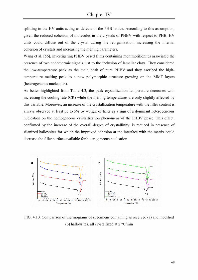
Chapter IV
69
splitting to the HV units acting as defects of the PHB lattice. According to this assumption,
given the reduced cohesion of molecules in the crystals of PHBV with respect to PHB, HV
units could diffuse out of the crystal during the reorganization, increasing the internal
cohesion of crystals and increasing the melting parameters.
Wang et al. [56], investigating PHBV based films containing montmorillonites associated the
presence of two endothermic signals just to the inclusion of lamellar clays. They considered
the low-temperature peak as the main peak of pure PHBV and they ascribed the high-
temperature melting peak to a new polymorphic structure growing on the MMT layers
(heterogeneous nucleation).
As better highlighted from Table 4.3, the peak crystallization temperature decreases with
increasing the cooling rate (CR) while the melting temperatures are only slightly affected by
this variable. Moreover, an increase of the crystallization temperature with the filler content is
always observed at least up to 5% by weight of filler as a sign of a dominant heterogeneous
nucleation on the homogeneous crystallization phenomena of the PHBV phase. This effect,
confirmed by the increase of the overall degree of crystallinity, is reduced in presence of
silanized halloysites for which the improved adhesion at the interface with the matrix could
decrease the filler surface available for heterogeneous nucleation.
FIG. 4.10. Comparison of thermograms of specimens containing as received (a) and modified
(b) halloysites, all crystallized at 2 °C/min
b a

Chapter IV
70
FIG. 4.11. Comparison of thermograms of specimens containing as received (a) and modified
(b) halloysites, all crystallized at 2 °C/min
FIG. 4.12 Comparison of thermograms of specimens containing as received (a) and modified
(b) halloysites, all crystallized at 10 °C/min
b a
a b

Chapter IV
71
TAB. 4.3 DSC thermal parameters of all investigated materials.

Chapter IV
72
In order to gain further insights into double-melting behavior, the PHBV endothermic signals
were analyzed remotely using a deconvolution route that, in all cases, allowed the evaluation
of melting enthalpies and some geometric parameters as the Full Width at Medium Height
(FWMH) of both low- and high-temperature peaks.
For example, the deconvolution of the double-melting signal related to composite films
containing 3% by weight of pure HNTs is shown in Fig.4.13.
FIG 4.13 Example of deconvolution of the melting signals
Results, in terms of enthalpy values (Table 4.4), show that, at the lowest crystallization rate,
composite films, compared with unfilled ones, display higher melting enthalpies and
crystallization temperatures which proved
the crystallization-promoting effect of halloysite. This effect disappears by increasing the
cooling rates probably due to the prevalence of the homogeneous crystallization phenomena.

Chapter IV
73
CR (°C/min) 2 5 10
Enthalpies (J/g) ΔHL ΔHH ΔHL ΔHH ΔHL ΔHM
Enmat 8.9 9.1 12.3 7.1 9.7 8.3
3 wt% HNTs 14.6 3.3 13.5 5.1 10.6 8.3
5 wt% HNTs 15.7 1.8 12.5 5.3 9.2 8.7
10 wt% HNTs 13.1 2.5 12.0 6.1 9.4 9.0
3 wt% f-HNTs 14.4 3.3 14.5 5.0 9.3 11.4
5 wt% f-HNTs 13.4 3.8 13.9 5.6 9.9 9.4
10 wt% f-HNTs 15.1 3.9 11.0 7.1 10.1 7.9
TAB.4.4 Enthalpies of low-temperature (L) and high-temperature (H)
melting signals
Moreover, besides the matrix, for which it seems that there isn’t a well-defined trend for
enthalpies of the signals at low and high temperature with the cooling rate, in the case of
nanocomposites it is clear that with increasing the crystallization rate, the area of the peak at
low temperature decreases while the area of the peak at high temperature increases.
At this regard, it is plausible to assume that the low-temperature signal is related to the
melting of uneven crystals produced by the homogeneous crystallization of the PHBV phase
while high-temperature one is due to the melting of more perfect crystals coming from the
nucleation action of the included filler nanoparticles. Thus, given the simultaneous occurrence
of both crystallization phenomena in all investigated systems, results show that the higher the
cooling rate the more pronounced is the effect of the heterogeneous nucleation. In other
words, given the extremely low crystallization rate of the PHBV phase, at high cooling rates
heterogeneous crystallization phenomena induced by the filler prevail on homogeneous ones
giving rise to more stable films, at least in terms of thermal properties.
As far as the Full Width at Medium Height (FWMH) is concerned, again composite films has
shown narrower melting signals and more symmetrical melting and crystallization curves,
with respect to the neat matrix suggesting a narrower crystal size distribution in the
nanocomposites then in the pure PHBV. This effect is enhanced by increasing the filler
content. Regarding the influence of cooling rate, instead, under the same filler content, the
increasing of this parameter leads to a narrowing of the low-temperature melting signals and a

Chapter IV
74
broadening of the high-temperature ones (see Table 4.5). This behavior is in line with the ever
more enhanced effect of heterogeneous nucleation phenomena with respect to homogeneous
one, by increasing the rate at which film samples are cooled.
CR (°C/min) 2 5 10
Sample FWMHL
(°C)
FWMHH
(°C)
FWMHL
(°C)
FWMHH
(°C)
FWMHL
(°C)
FWMHH
(°C)
Enmat 44.3 36.8 40.7 27.5 64.2 31.6
3 wt% HNTs 39.8 21.6 44.4 25.1 59.4 27.1
5 wt% HNTs 36.0 17.8 42.1 25.9 57.9 31.6
10 wt% HNTs 33.2 11.6 44.9 26.9 51.6 28.6
3 wt% f-HNTs 42.1 22.1 50.9 25.1 61.0 37.9
5 wt% f-HNTs 43.4 23.2 53.6 28.6 49.7 31.0
10 wt% f-HNTs 43.2 22.1 42.8 29.2 56.0 31.6
TAB 4.5 Full Width at Medium Height (FWMH) of low-temperature (L) and high-
temperature (H) melting signals
4.5.4 X-Ray Diffraction Analysis
Structural features of both film samples and specimens, crystallized during DSC cooling
scans, have been studied by X-ray diffraction analysis. The diffraction patterns of ENMAT in
pellet (curve A) and in film form (curve B) have been reported in Fig. 4.14 indicating
reflections of PHBV and PBAT phases with filled circles and filled squares, respectively [57-
60]. The diffraction pattern B of of Figure 4.14 shows that during the film blowing process
both PHBV and PBAT phases crystallize.

Chapter IV
75
FIG.4.14 X-ray diffraction patterns of ENMAT in pellet form (A) and in film form (B):
(filled circles) reflections of PHBV phase; (filled squares) reflections of PBAT phase.
Moreover, narrower reflections of pattern B with respect to the ones characterizing pattern A,
suggest the presence of more perfect crystals in the film form (e. g. for PHBV orthorhombic
crystals D020 increases from 14,5 to 30,1 nm). Diffraction patterns of composites containing as
received and modified HNTs have been reported in Figures 4.15 and 4.16. In both figures the
diffraction patterns of the polymer matrix and the filler have been reported. In these pictures,
reflections characterizing the PHBV and PBAT crystalline phases have been highlighted with
filled symbols, while reflections of the HNTs crystalline phases have been indicated as empty
triangles [61].

Chapter IV
76
FIG. 4.15 X-ray diffraction patterns for films containing pure HNTs: (filled symbols)
reflections of PHBV and PBAT crystalline phases; (empty triangles) reflections of HNTs
crystalline phase.
FIG.4.16 X-ray diffraction patterns for films containing modified HNTs: (filled symbols)
reflections of PHBV and PBAT crystalline phases; (empty triangles) reflections of modified
HNTs crystalline phase.
In these cases, in line with calorimetric results, the presence of the filler, although it may alter
the kinetics and mechanisms of crystallization, does not seem to affect the degree of
crystallinity of the PBAT phase. The intensity ratio between the reflections of the HNTs

Chapter IV
77
phase is strongly altered in composite films, while the positions remain unchanged. In
particular, 001 and 002 reflections are much more intense and the 020 reflection is negligible.
This indicates a preferred orientation of the HNTs basal planes parallel to the film plane.
Such orientation has been confirmed by X-ray diffraction patterns, taken with beam parallel to
the film plane and collected on a photographic cylindrical camera. In this respect, the
diffraction pattern of the composite film containing 10 %wt. of HNTs, reported in Figure
4.17, shows intense 001 reflection arcs centered on the equatorial line.
FIG. 4.17 X-ray diffraction pattern, taken with beam parallel to the film plane and collected
on a photographic cylindrical camera, for the composite film containing 10 %wt. of HNTs.
In Figure 4.18 diffraction patterns of specimens containing HNTs, all crystallized at 5 °C/min
during DSC cooling scans, have been compared. For all specimens, PHBV phase crystallizes,
while PBAT phase is essentially amorphous. HNTs basal reflections are only slightly visible
even for composites with 10 %wt. of filler. Such results have been confirmed by X-ray

Chapter IV
78
diffraction patterns, collected on a photographic cylindrical camera, of specimens crystallized
at 5 °C/min during DSC cooling scans. Actually, in the diffraction pattern of the specimen
with 10 %wt. of HNTs the 001 reflection becomes negligible. This behavior can be attributed
to the occurrence of a complete disorientation of the added halloysites associated with the
polymer melting.
Strictly similar results have been obtained for specimens crystallized at cooling rates of 2 and
10 °C/min.
FIG.4.18 X-ray diffraction patterns for specimens containing HNTs all crystallized at 5
°C/min: (filled symbols) reflections of PHBV and PBAT phases; (empty triangles) reflections
of HNTs crystalline phase.
Conclusions
Bio-composites, based on a commercial PHBV/PBAT blend and loaded with natural or
chemically functionalised halloysite nanotubes, have been analysed and interpreted in terms
of calorimetric and structural tests.
Results showed the crystallization of both phases constituting the matrix with a dominant
contribution from the copolymer PHBV. Such crystallinity, improved by orientations, induced
by the film technology, that may, among other things, facilitate the formation of more perfect
Chapter IV
79
crystals, is not homogeneously influenced by the inclusion of halloysites. In particular,
although the filler may influence the kinetics and mechanisms of crystallization, the
investigations demonstrated that, for composite films, the slight crystallization of PBAT
remained unchanged, while there was an increase of the degree of crystallinity of the PHBV
phase.
The analysis of samples crystallized at a controlled rate showed the splitting of the PHBV
melting signal attributed to simultaneous phenomena of homogeneous crystallization and
heterogeneous nucleation of PHBV phase.

Bibliography
80
[1] A.K. Bledzki and J. Gassan, Prog. Polym. Sci. 24(2), 221m(1999).
[2] K.-K. Yang, X.-L. Wang, and Y.-Z. Wang, J. Ind. Eng. Chem. 13(4), 485 (2007).
[3] Q. Zhang, Q. Liu, J.E. Mark, and I. Noda, Appl. Clay Sci. 46, 51 (2009).
[4] S. Bhuyan, S. Sundararajan, Y. Lu, and R.C. Larock, Wear 268(5–6), 797 (2010).
[5] I. Armentano, M. Dottori, E. Fortunati, S. Mattioli, and J.M. Kenny, Polym. Degrad.
Stab. 95(11), 2126 (2010).
[6] P. Russo, C. Carfagna, F. Cimino, D. Acierno, and P. Persico, Adv. Polym. Technol.
(2012) DOI: 10.1002/adv.21282.
[7] J.K. Pandey, S.H. Ahn, C.S. Lee, A.K. Mohanty, and M. Misra, Macromol. Mater.
Eng. 295, 975 (2010).
[8] C.J. Song, S.F. Wang, S. Ono, B.H. Zhang, C. Shimasaki, and M. Inoue, Polym. Adv.
Technol. 14, 184 (2003).
[9] L.L. Madison and G.W. Huisman, Mol. Biol. Rev. 63, 21 (1999).
[10] A. Marcilla, J.C. Garcia-Quesada, and E. Gil, J. Appl. Polym. Sci. 110(4), 2102
(2008).
[11] J. Tao, C. Song, M. Cao, D. Hu, L. Liu, N. Liu, and S. Wang, Polym. Degrad. Stab.
94(4), 575 (2009).
[12] B.M.P. Ferreira, C.A.C. Zavaglia, and E.A.R. Duek, J. Appl. Polym. Sci. 86(11), 2898
(2002).
[13] L. Miao, Z. Qiu, W. Yang, and T. Ikehara, React. Funct. Polym. 68(2), 446 (2008).
[14] T. Sadik, V. Massardier, F. Becquart, and M. Taha, J. Appl. Polym. Sci. (2012) DOI:
10.1002/app.37957.
[15] M.J. Jenkins, Y. Cao, L. Howell, and G.A. Leeke, Polymer 48(21), 6304 (2007).
[16] A. Javadi, A.J. Kramschuster, S. Pilla, J. Lee, S. Gong, and L.-S. Tumg, Polym. Eng.
Sci. 50(7), 1440 (2010).
[17] A. Javadi, Y. Srithep, J. Lee, S. Pilla, C. Clemons, S. Gong, and L.-S. Turng, Compos
Part A: Appl. Sci. Manuf. 41(8), 982 (2010).
[18] H.M. Cordeiro de Azeredo, L.H. Caparelli Mattoso, and T.H. McHugh,
‘‘Nanocomposites in Food Packaging—A Review’’ in Advances in Diverse Industrial
Applications of Nanocomposites, B. Reddy, Ed., InTech, (2011). ISBN: 978- 953-307-202-9.
Rijeka, Croatia, pp. 57–78.

Bibliography
81
[19] L. Incarnato, P. Scarfato, G.M. Russo, L. Di Maio, P. Iannelli, and D. Acierno,
Polymer 44, 4625 (2003).
[20] L. Incarnato, L. Di Maio, E. Garofalo, and P. Scarfato, ‘‘Polylactide nanocomposites
as a new solution for eco-compatible packaging materials’’ in 5th International Conference on
Times of Polymers (TOP) and Composites. AIP Conference Proceedings Vol. 1255, Ischia
(Italy), June 20–23, 364 (2010).
[21] G. Tari, I. Bobos, C. Gomes, and J. Ferreira, J. Colloids Interface Sci. 210, 360 (1999).
[22] N. Veerabadran, Y. Lvov, and R. Price, Macromol. Rapid Commun. 30, 94 (2009).
[23] H. Noro, Clay Miner. 21, 401 (1986).
[24] Guo B., Lei Y., Chen F., Liu X., Du M., Jia D.: Applied Surface Science, 255, 2715–
2722 (2008).
[25] Liu M., Guo B., Zou Q., Du M., Jia D. Nanotechnology, 19, 205709 (2008).
[26] Du M., Guo B., Lei Y., Liu M., Jia D. Polymer, 49, 4871–4876 (2008).
[27] Ye Y., Chen H., Wu J., Ye L . Polymer, 48, 6426–6433 (2007).
[28] Deng S., Zhang J., Ye L., Wu J. Polymer, 49, 5119–5127 (2008).
[29] Marney D. C. O., Russell L. J., Wu D. Y., Nguyen T., Cramm D., Rigopoulos N.,
Wright N., Greaves M.Polymer Degradation and Stability,93, 1971–1978 (2008).
[30] Ismail H., Pasbakhsh P., Fauzi M. N. A., Abu Bakar A.Polymer Testing, 27, 841–850
(2008).
[31] Hedicke-Höchstötter K., Lim G. T., Altstädt V. Composites Science and Technology,
69, 330 334 (2009).
[32] Liu M., Guo B., Du M., Chen F., Jia D. Polymer, 50, 3022–3030 (2009).
[33] Du M., Guo B., Jia D. European Polymer Journal, 42, 1362–1369 (2006).
[34] Ning N-Y., Yin Q-J., Luo F., Zhang Q., Du R., Fu Q. Polymer, 48, 7374–7384 (2007).
[35] S.R. Levis and P.B. Deasy, Int. J. Pharm. 253, 145 (2003).
[36] H.M. Kelly, P.B. Deasy, E. Ziaka, and N. Claffey, Int. J. Pharm. 274, 167 (2004).
[37] S.J. Antill, Aust. J. Chem. 56(7), 723 (2003).
[38] D.G. Shchukin, G.B. Sukhorukov, R.R. Price, and Y.M. Lvov, Small 1(5), 510
(2005).

Bibliography
82
[39] S. Barrientos-Ramirez, E.V. Ramos-Fernandez, J. Silvestre- Albero, A. Sepulveda-
Escribano, M.M. Pastor-Blas, and A. Gonzalez-Montiel, Micropor. Mesopor. Mater. 120, 132
(2009).
[40] A.P. Wang, F.Y. Kang, and Z.H. Huang, Micropor. Mesopor. Mater. 108(1–3) 318
(2008).
[41] P. Liu and M. Zhao, Appl. Surf. Sci. 255, 3989 (2009).
[42] M. Zhao and P. Liu, Micropor. Mesopor. Mater. 112, 419 (2008).
[43] M.T. Viseras, C. Aguzzi, P. Cerezo, C. Viseras, and C. Valenzuela, Micropor.
Mesopor. Mater. 108, 112 (2008).
[44] P. Luo, Y. Zhao, B. Zhang, J. Liu, Y. Yang, and J. Liu, Water Res. 44, 1489 (2010).
[45] P.J. Barham, A. Keller, E.L. Otun, and P.A. Holmes, J. Mater. Sci. 19(9), 2781 (1984).
[46] Chivrac, F., Kadlecova, Z., Pollet, E., Averous, L.. Journal of Polymers and the
Environment, 14(4), 393 (2006)
[47] Pooria Pasbakhsh, H. Ismail, M.N Ahmad Fauzi, A. Abu Bakar Applied Clay Science
48 ,405–413 (2010)
[48] Shufang Wang, Cunjiang Songb, Guangxin Chena, Tianying Guoa, Jing Liub,
Banghua Zhang, Shigeya Takeuchi, Polymer Degradation and Stability 87 69 (2005)
[49] Mohanty, S. and Nayak, S. K..Polym Compos, 31: 1194 (2010)
[50] Larissa N. Carli,Janaina S. Crespo,Raquel S. Mauler. Composites Part A: Applied
Science and Manufacturing, 42, 11, 1601 (2011).
[51] Technical report of Imerys Tableware Asia Limited available
from:http://www.imerys-tableware.com/halloy.html.
[52] Y. Lee and R.S. Porter, Macromolecules 20, 1336 (1986).
[53] M. Yasuniwa, S. Tsubakihara, Y. Sugimoto, and C. Nakafuku, J. Polym. Sci. Part B:
Polym. Phys. 42(1), 25 (2004).
[54] Z.B. Qiu, T. Ikehara, and T. Nishi, Polymer 44, 3095 (2003).

Bibliography
83
[55] A.J. Owen, J. Heinzel, Z. Skrbic, and V. Divjakovic, Polymer 33(7), 1563 (1992).
[56] S. Wang, C. Song, G. Chen, T. Guo, J. Liu, B. Zhang, and S. Takeuchi, Polym.
Degrad. Stab. 87, 69 (2005).
[57] M. Kunioka, A. Tamaki, and Y. Doi, Macromolecules 22, 694 (1989).
[58] Z ˇ . Sˇ krbic´ and V. Divjakovic´, Polymer 37(3), 505 (1996).
[59] M. Lai, J. Li, J. Yang, J. Liu, X. Tong, and H. Cheng, Polym. Int. 53, 1479 (2004).
[60] F. Yang and Z. Qiu, J. Appl. Polym. Sci. 119, 1426, (2011).
[61] I. Bobos, J. Duplay, J. Rocha, and C. Gomes, Clay Clay Miner. 48(6), 596 (2001).

Chapter V
Rheological behavior of
biodegradable nanocomposites filled
with Halloysite: effect of filler
functionalization

Chapter V
5.1 Introduction
Today manufactures of plastic products and packages have to meet several requests, such
as low cost , improved mechanical and barrier performance. In line with this trend, in the
last decades a huge effort of the research has been focused on the reinforcement of
polymers by the addition of nanofillers such as clay minerals or carbon nanotubes[1-10].
An appropriate dispersion, distribution, and compatibility between the nanofillers and the
polymeric matrix are key features to obtain an enhancement on biodegradability [11,12]
and flammability [13,14] besides an improvement of mechanical [15,16], thermal [17,18]
and barrier [19,20] properties.
Silicate nanoplatelets, e.g., montmorillonite and carbon nanotubes are the most used
fillers in polymer nanocomposites [21-23].
However, Halloysite nanotubes (HNTs), a naturally occurring clay mineral, is attracting
interest for fabrication of high performance materials based on polymers.
Halloysite(Al2Si2O5(OH)4•nH2O), is a mineral chemically similar to kaolin but
exhibiting a predominantly tubular morphology.
This clay consists of hollow tubes with dimensions that generally vary from 50 to 70 nm
in external diameter, a ca. 15-nm diameter lumen, and 0.5 to 2 μm in length [24].
HNT nanotubes represent an alternative to carbon nanotubes(CNT) because its costs
competitiveness, natural availability and biocompatibility.
HNTs are a new type of additive for enhancing the mechanical properties, thermal
stability and anti-flammability characteristics of polymer matrices [25-29].
Recently HNTs have been incorporated into various biopolymers[30-32].
In recent decades, a large amount of researches have been made on biodegradable
polymers to overcome environmental problems associated with conventional plastic
waste.
Aliphatic polyesters such as poly(-hydroxybutyrate-co-hydroxybutyrate) PHBV, which
have higher flexibility and lower processing temperatures than the homo-polymer
Poly(3-hydroxybutyrate) (PHB), are attractive candidates for many applications owing to
their biodegradability and biocompatibility[33,34]. However the use of PHBV is still
limited by some drawbacks such as slow crystallization rate, relatively difficult
processing, low elongation at break, and very high degree of crystallinity. Blending

Chapter V
86
PHBV with other biodegradable polymers such as PLA[35] ,PCL,[36] or cellulose and
starch derivatives [37,38] is way of obtaining new materials with improved properties,
which can overcome the drawbacks of the PHBV.
Poly- (butyleneadipate-co-terephthalate) (PBAT) is an aliphatic-aromatic co-polyester
with high toughness but it is also biodegradable and compostable. Accordingly, PBAT is
an excellent candidate for toughening PHBV.
The matrix used in this research, currently supplied by a Chinese firm, involves these two
biodegradable resins:
PHBV and PBAT in a blend with a weight ratio equal to 30:70, respectively.
There are few research reports showing properties of this blend[39-43], but HNTs
reinforced PBAT/ PHBV nanocomposites have never been reported.
Polymer nanocomposites with functional properties, including biocompatibility,
compostability, and mechanical properties may be designed by using HNTs as filler in
PBAT/PHBV matrix.
The investigation of the effect of Halloysite nanotubes loading, nanotubes
functionalization and temperature on the rheological behavior of the nanocomposites was
the main objective of this chapter.
Experimental section
5.2 Materials and surface modification of the clay.
A blend of PBAT/PHBV with 70:30 weight ratio, was supplied, in pellet form, from
Ningbo Tianan Biologic Material Co. Ltd. (Tianan-ENMAT) (China) under commercial
name 6010P and in this study denoted as Enmat. Halloysite nanotubes (HNTs), used as
filler, with average sizes equal to: 0.25-4 nm (length), 30 nm (diameter), 64 m2/g (surface
area) and a specific gravity 2.53 g/cm3 were provided by Sigma-Aldrich.
As confirmed by X-ray diffraction analysis Halloysite was in the dehydrated state s

Chapter V
87
showing a diffraction signal at 12.138 corresponding to a (001) basal spacing of
approximately 7.3Å.
Modification of Halloysite clay was made according to a well established procedure
reported elsewhere [26]
The successful functionalization of Halloysite particles was verified by ATR-FTIR
spectroscopy.
The pellet(Enmat) and the clay nanotubes , unmodified (HNTs) and chemically modified
(f-HNTs) were dried under vacuum at 70°C for at least 12 hrs prior to use.
5.3 Processing of biodegradable nanocomposites
The nanocomposites of Enmat with Halloysite ,as received and modified, were prepared
using melt compounding technique in a co-rotating twin screw extruder (HAAKE
PolyLab, L/D=40).
The bio-polymer were melt mixed with the filler at different weight percentage (3, 5, 10
wt%) maintaining the processing temperature at 150-155-160-165-165-160-160-160 °C
from feed to die zone of extruder and setting the screw speed at 100 rpm. Pure Enmat
was also extruded under the same conditions to use as reference material. Subsequently
the extruded materials was pelletized to granules and dried overnight at 70 °C to remove
the water absorbed after extrusion.
Systematic thermogravimetric measurements, shown in previous chapter , confirmed a
good agreement between nominal and actual filler contents.

Chapter V
88
Formulation Abbrevation
PBAT/PHBV
PBAT/PHBV+3% Halloysite
PBAT/PHBV+5%Halloysite
PBAT/PHBV+10%Halloysite
PBAT/PHBV+3% silanized Halloysite
PBAT/PHBV+5% silanized Halloysite
PBAT/PHBV+10%silanized Halloysite
Enmat
3%HNTs
5%HNTs
10%HNTs
3% f-HNTs
5% f-HNTs
10% f-HNTs
5.4 Characterization Techniques
5.4.1 Fourier Transform Infrared Spectroscopy (FTIR)
To confirm the chemical interaction of silane with nanotube surface the nanoparticles
were analyzed by infrared spectroscopy. The FTIR-ATR instrument used was a Nicolet
6700 (Thermo Scientific) operating in the wavenumber range of 650 to 4000 cm-1
, with
ZnSe crystal, 32 scans and 4 cm-1
resolution.
5.4.2 Rheological characterization
Shear rheology of the polymer melt is a useful tool to characterize the materials and to
determine their processing performance.
There are two techniques normally utilized to determine the shear rheological behavior of
a material:
Dynamic shear rheology
Steady shear rheology
Shear rheological techniques are used to determine the flow behavior and structure
evolution of a material under the influence of a steady-state deformation.

Chapter V
89
Dynamic rheology is a structural analysis tool because it uses a frequency excitation
method to determine the molecular-level structure of a polymeric system[43].
Small strain dynamic shear rheological properties are generally considered to obtain the
elastic and viscous response of the materials, while the processing properties are
estimated analyzing rheological behavior at high frequencies.
In order to verify the processability of nanocomposite samples and to establish the
nanodispersion structure, capillary and parallel plate rheometers have been considered in
this study to characterize the rheological properties of the investigated nanocomposite
systems.

Chapter V
90
5.4.3 Oscillatory measurements
Dynamic and steady-state tests were carried out on a controlled stress rheometer (SR 500 ,
Rheometric Scientific) equipped with a parallel plate geometry (25 mm diameter, gap ~1
mm) at 160°, 170° and 180°C. The samples were directly melted for 5 min between
preheated parallel plates to erase thermal history and to avoid any further rearrangement
and/or failure of brittle clay nanotubes. The dynamic experiments were run setting an
angular frequency from 0,01 to 100 rad/s under a constant amplitude of 5%. In advance
a strain sweep test were performed to assure that the tests were in the linear
viscoelasticity region. All measurements were conducted under a nitrogen atmosphere to
minimize oxidative degradation of matrix.
FIG.5.1 Schematic of a parallel plate rheometer

Chapter V
91
5.4.4 Steady shear capillary measurements
All the investigated compounds and the neat matrix, taken as the reference material, were
subjected to capillary extrusion. At this purpose an instrument (ACER 2000, Rheometric
Scientific) having a barrel diameter of 20 mm and a capillary die (D=1mm – L/D=30) was
used.
Measurements on predried pellets were conducted at 160, 170 and 180°C.
Results reported as viscosity vs shear rate, on the range 30-103
s-1
, were corrected
according to the Moony-Rabinovitch approach but neglecting Bagley corrections.
FIG 5.2 Schematic of capillary rheometer

Chapter V
92
5.4 Results and discussion
5.4.1 Fourier Transform Infrared Spectroscopy (FTIR)
As discussed in chapter IV, the absorption bands at 1720 and 1635 cm-1
are associated to
the stretching vibrations of C- O and C- C groups.
The band at 1470 is attributed to deformation vibrations of C–H in CH2 bonds . The
asymmetric and symmetric stretching vibrations of C–O of
C–O–C bonds are attributed to bands at 1320 and 1296 cm_1, respectively. All those
bands are related with the non-hydrolyzable part of the MPS molecule [44]. In fact the
first step of the silanization process was hydrolysis of the silane in ethanol under stirring
at room temperature.
This process can be represented:
R-Si-(OR’)3 R-Si-(OH)3
FIG. 5.3 Molecular structure of MPS
FIG.5.4 FTIR spectra of as received and modified Halloysite
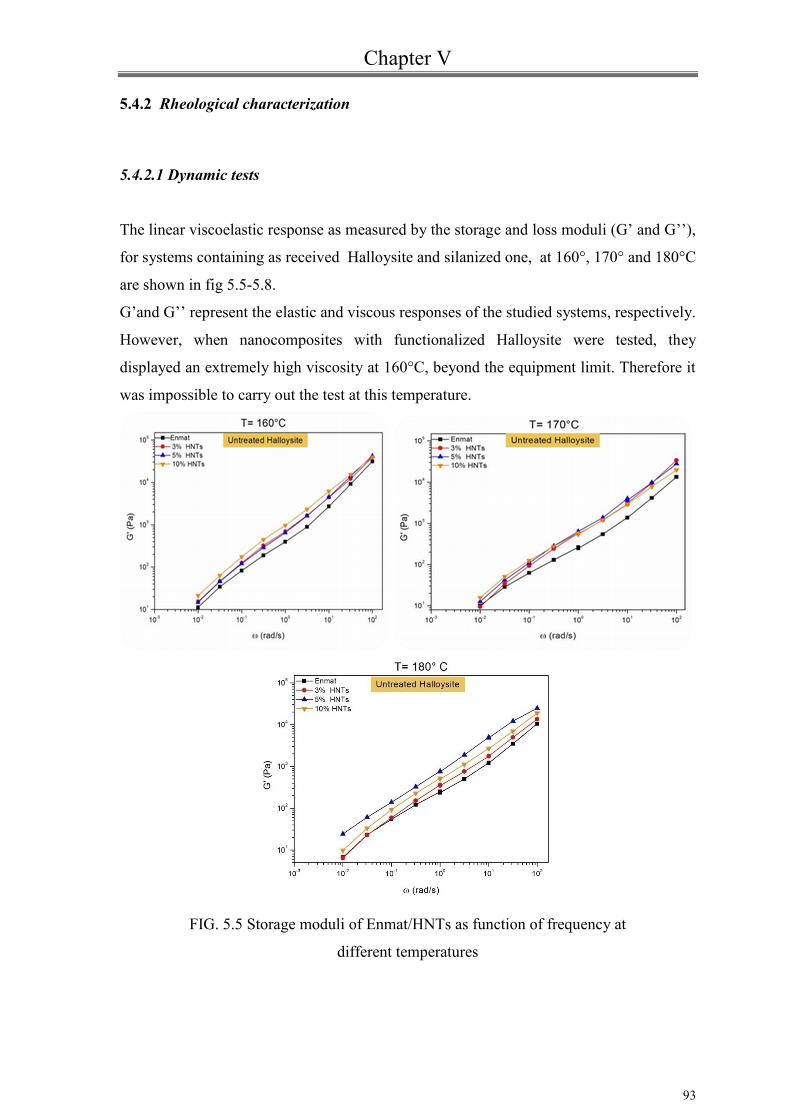
Chapter V
93
5.4.2 Rheological characterization
5.4.2.1 Dynamic tests
The linear viscoelastic response as measured by the storage and loss moduli (G’ and G’’),
for systems containing as received Halloysite and silanized one, at 160°, 170° and 180°C
are shown in fig 5.5-5.8.
G’and G’’ represent the elastic and viscous responses of the studied systems, respectively.
However, when nanocomposites with functionalized Halloysite were tested, they
displayed an extremely high viscosity at 160°C, beyond the equipment limit. Therefore it
was impossible to carry out the test at this temperature.
FIG. 5.5 Storage moduli of Enmat/HNTs as function of frequency at
different temperatures

Chapter V
94
FIG. 5.6 Storage moduli of Enmat/ f-HNTs as function of frequency at different
temperatures
The rheological behaviour of polymer composites depends, among other things, on the
material microstructure, the fillers dispersion, the aspect ratio and orientation of the
fillers, the interaction polymer-filler interaction and as well as filler-filler
interactions[45,46]. The temperature can influence the rheological properties of the
matrix changing the particle–particle interactions and the wettability of the fillers with the
matrix [46].
Analyzing the curves in fig.5.5-5.6 , it can be seen that the incorporation of halloysites
induces an increase of the storage modulus of the neat matrix all over the considered
range of oscillation frequency. This effect is not monotonous with the filler content with
a trend varying with the testing temperature probably for the occurrence of different level
of filler distribution leading different extent of interaction with the surrounding matrix. .
It is clearly seen that silanized Halloysites influence the storage modulus and this effect is
pronounced especially at low frequencies.
The slopes of G’(ω) curves in the terminal zone were calculated and listed in tables 5.1-
5.2. With the inclusion of clay nanotubes, a slight increase of the slopes of the low
frequency region of G’ is observed, as listed in the table 5.1. This trend, usually ascribed
to the occurrence of microstructural changes, seems to reach the maximum extent at the
temperature of 170 °C.
Moreover, even at the largest filler fraction so far investigated, no indication of a solid

Chapter V
95
like behavior (plateau of G’ at low frequencies) can be noted. The absence of a
percolating network can be attributed to the low initial aspect ratio of the halloysiste
nanotubes, usually further reduced by shear in melt processing steps.
Sample Low-frequency slop of G' vs ω<0.1
160 °C 170 °C 180 °C
Pure Enmat 0.87 0.82 0.90
Enmat/3 wt% HNTs 0.92 0.99 0.96
Enmat/5 wt% HNTs 0.91 0.93 0.75
Enmat/10 wt% HNTs 0.92 0.89 0.96
TAB.5.1 terminal slope of G′ at different temperatures for different
amounts of HNTs loadings
But it can be also seen from table 5.2 that, when modified halloysite is used, the
nanocomposites have smaller low-frequency slope of storage modulus G’ versus
frequency ω.
Sample Low-frequency slop of G' vs ω<0.1
170 °C
180 °C
Pure Enmat 0.82
0.90
Enmat/3 wt% Silanized HNTs 0.78
0.79
Enmat/5 wt% SilanizedHNTs 0.57
0.67
Enmat/10 wt% SilanizedHNTs 0.31
0.35
TAB.5.2 terminal slope of G′ at different temperatures for different
amounts of f-HNTs loadings
The dependence of G’ on ω at low frequencies becomes very weak.
Nevertheless no indication of a solid-like behavior (plateau of G’ at low frequencies) can
be observed.
At this regard, it is well know that for nano-structured systems two critical concentrations

Chapter V
96
accounting for structural transitions of nanodispersions with increasing nanofiller content
are verified. These latter are best known as flocculation threshold and percolation
threshold and described as follows:
1. The rheological flocculation threshold expresses the critical nanofiller concentration,
where the short-range connectivity of the nanofiller particles becomes significant
resulting in flocculation. The fractal floccules consist of near uniform nanofiller
agglomerates penetrated with a matrix polymer.
2. The rheological percolation threshold represents the long-range connectivity of the
fractal flocs within the polymer matrix, resulting in the formation of a three-dimensional
(network) supramolecular structure [47].
In light of the above considerations, for systems containing silanized clay nanotubes the
occurrence of flocculation rather than percolation phenomena can be assumed.
Figures 5.7 and 5.8 represent the loss modulus G’’ of neat Enmat and composites
containing as received and silane-treated HNTs, respectively.
The trend of the loss modulus can not indicate more useful information. As expected, it
can only show, also in this case, values of the slopes of the curves at low frequencies

Chapter V
97
lower than the theoretical one usually valid for linearly homo-dispersed polymer melts.
FIG.5.7 The variation in loss modulus with frequency for
Enmat/HNTs nanocomposites at different temperatures.

Chapter V
98
FIG.5.8 The variation in loss modulus with frequency for
Enmat/ f-HNTs nanocomposites at different temperatures.
In fig. 5.9 comparisons of investigated materials in terms of loss modulus are depicted.
As expected, the loss tangent, tan δ, where δ is the phase angle is shown Figure 5.9 to be
very sensitive to the structural change of the materials.

Chapter V
99
FIG. 5.9 tan δ of HNTs nanocomposites as functions of the frequency at
different temperatures
The damping intensity is lowered by increasing the clay nanotube concentration with an
effect further emphasized by increasing the temperature of the test.
This behavior confirms that the nanocomposites are more elastic than the reference
extruded matrix over all frequency range at molten state and that both energy dissipation
and relaxation of the matrix chains are increasingly hindered as the filler loading
increases.
The influence of the temperature may be explained assuming the achievement of different
filler distribution and, consequently, by the enable of various extent of filler matrix
interactions.

Chapter V
100
As highlighted in fig.5.10, the above mentioned effects are further enhanced with the
improvement of the filler-matrix interface.
FIG. 5.10 tan δ of nanocomposites containing functionalized Halloysite as functions of
the frequency at different temperatures
The peaks occur at the frequency of about 10 rad/s and almost disappear with increasing
nanotube content, showing that the material becomes more elastic.
The change in complex viscosity of the neat Enmat and Enmat/HNTs nanocomposites is
shown in figures 5.11.
All materials containing untreated halloysites show a shear thinning behavior over all the
analyzed oscillation frequency range.
An increase of the complex viscosity is verified for formulations including HNTs with
respect to the reference matrix.
The extent of this effect varies with the testing temperature and the filler content.
For systems with inproved interfacial regions(Fig. 5.12) a slight drift of the viscosity
curve is observed for the highest filler content in the low frequency zone: behavior in line
with the assumed occurrence of flocculation phenomena.

Chapter V
101
FIG.5.11 Frequency dependence of complex viscosity η* at different temperatures for
Enmat/HNTs nanocomposites
FIG.5.12 Frequency dependence of complex viscosity η* at different temperatures for
Enmat/f-HNTs nanocomposites

Chapter V
102
The interesting thing to note is that, unlike the previous case, the complex viscosity
increases with the addition of modified nanotubes to the pure blend as better emphasized
in graphs 5.13 and 5.14. In these plots the complex viscosity as a function of the filler
content at various frequencies is reported.
The complex viscosity clearly depends on the filler content especially at low frequencies
as well as on the testing temperature.
The effect, essentially related to the predominance at low frequencies of physical filler-
filler and/or filler-matrix interactions, is emphasized by reducing the testing temperature.
In other words, as expected, the wettability of clay nanotubes by the hosting matrix is
reduced by increasing temperature.
The effect of the filler loading on the viscosity of the matrix becomes, as expected,
particularly marked at low frequencies if the interface is improved by adequate pre-
treatments of the included particles.
Clearly at 170 ° C there is an increase of an order of magnitude of the viscosity at 0.01
Hz: effect reduced by about 50% at 180 °C due to the increased mobility of
macromolecules constituting the matrix and, consequently, to the lower wettability of
included clay nanotubes.

Chapter V
103
FIG 5.13 Complex viscosity *: effect of HNTs content at
various frequencies
FIG 5.14 Complex viscosity *: effect of silanized HNTs content at
various frequencies

Chapter V
104
In order to understand the effect of temperature on the rheological properties the
Andrade-Eyring equation defined for the complex viscosity [48] has been employed in
which:
Ea is the flow activation energy and R is the universal gas constant equal to 8.314 J/n K.
In the case of nanocomposites, Ea can be related to the interactions between polymer
chains and fillers. The value of Ea thus depends on the ease with which the fillers move
through the polymer chains. The plot(fig. 5.15-5.16) of the values of ln η* (determined
at 1 rad/s) as a function of 1/RT makes to estimate the activation energy of the
nanocomposites, given by the slope of this curve. Table 5.3 and 5.4 report the values of
Ea for different nanotube loadings.
FIG.5.15 Linearized Andrade-Eyring TAB.5.3 Activation energy values
relationship for systems containing pure HNTs
The activation energy increases with the clay nanotube loading. The influence is
explainable assuming that the higher filler concentrations, the more constrained is the
flow of compound melts.
Filler
content
B (Pa s)
106
Ea (J/n)
3 wt%
5 wt%
5,25
0,16
7,17
8,46
10 wt% 0,048 8,95
RT
Ea
eB *

Chapter V
105
Although in the case of organo- modified fillers it is improper to speak about data fitting
because, given the particularly high viscosity of the system at 160 °C, there are only two
points(fig. 5.16), it seems that in this case the activation energy values are higher than
those evaluated for analogous materials containing as received clay nanotubes.
In other words, as expected, the improvement of the filler-matrix interface induces further
constraints to the flow of the host matrix macromolecules.
FIG.5.15 Linearized Andrade-Eyring TAB.5.3 Activation energy values of
relationship systems containing modified HNTs
The steady shear behavior of polymer/clay nanocomposites usually allows to obtain
useful information on processability of the material [49]
In Fig. 5.16 the steady-shear rheological behavior of neat Enmat and its nanocomposites
with Halloysite are reported.
Each flow curve shows two distinct regions: the first one with shear viscosity almost
constant with the shear rate (at low shear) rates and the second one at higher shear rates
where the shear viscosity decreases with an increasing shear rate. There is a transition
from a Newtonian region to a power-law region.
To investigate the dependence of the viscosity on the shear rate, Carreau model [50] was
employed to fit the non-Newtonian viscosity curve (square symbols) for neat Enmat and
its nanocomposites, as shown in Figure 5.17 (solid lines).
Filler
content B (Pa s) 10
6 Ea (J/n)
3 wt% 0,37 8,33
5 wt% 0 16,50
10 wt% 0,092 9,80
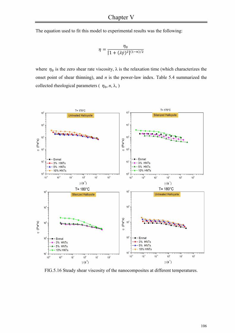
Chapter V
106
The equation used to fit this model to experimental results was the following:
where is the zero shear rate viscosity, λ is the relaxation time (which characterizes the
onset point of shear thinning), and n is the power-law index. Table 5.4 summarized the
collected rheological parameters ( n, λ, )
FIG.5.16 Steady shear viscosity of the nanocomposites at different temperatures.

Chapter V
107
FIG.5.17 Example of comparison of the Carreau model fit to the
experimental data
170°C 180°C
Sample
η0x10-3
(Pa.s)
λ
(s)
(s-1
)
Sample
η0x10-3
(Pa.s)
λ
(s)
(s-1
)
Enmat 1,9 5,9 0,82 0,16 Enmat 0,87 4,5 0,84 0,11
3%HNTs 2,1 7,5 0,77 0,13 3%HNTs 1,1 7,1 0,84 0,14
5%HNTs 1,7 8,4 0,83 0,12 5%HNTs 1,3 8,8 0,84 0,11
10%
HNTs 3,3 13,6 0,73 0,07
10%
HNTs 1,6 11,1 0,83 0,09
3%f-
HNTs 2,0 30,3 0,80 0,03
3%f-
HNTs 0,83 3,0 0,82 0,12
5%f-
HNTs 1,5 20,0 0,80 0,05
5%f-
HNTs 0,81 4,0 0,82 0,25
10%f-
HNTs 3,4 18,1 0,75 0,05
10%f-
HNTs 2,1 10 0,70 0,1
TAB. 5.4 Parameters in Carreau model

Chapter V
108
Clearly at 170° the degree of shear thinning (1 - n) and λ increases with the clay content.
the critical shear rate γ c is defined as the onset point of shear-thinning transition and is
approximately equal to the inverse of λ[51].
Hence, considering the values in table 5.4, the addition of clay shifts the transition from
the Newtonian plateau region to shear-thinning region occurring at lower critical shear
rate with increasing the clay concentration. This might suggest that the fillers are ease of
orientation in response to externally applied stress.
Regarding results at 180° for systems containing surface modified clay nanotubes
significant benefits are shown only by the 10% by weight loaded system. Probably this
decrease in viscosity is caused by thermal degradation of the material that occurs during
the testing . However, the parameter λ decreases with increasing temperature. The
decrease in relaxation time with increasing temperature is due to the increased mobility of
the polymer chains and the lower wettability of included clay nanotubes. The Newtonian
plateau is extended at higher frequencies.
5.4.2.2 Steady shear capillary measurements
Capillary experiments allow to determine the flow properties at large share rates. Shear
rate in an extrusion can be determined by the following equation[51]:
where is the screw speed in RPM, H is of the order of one tenth of the barrel radius(R),
the angular velocity ω in rad/s is 2πν/60.
Therefore, to verify the extrudability of the investigated nanocomposite systems, three
temperatures were selected for each set measure, each of them including the range
temperature used during extrusion.
Figures 5.18 and 5.19 present the results of the capillary measurements of the studied
samples at the three different temperatures.

Chapter V
109
FIG.5.18 Comparison of viscosities of Enmat/HNTs composites
Nanocomposites show a flow behavior, at high share rate, not influenced by the
presence of filler with respect to the reference pure matrix even in case of improved
filler-matrix interface (fig.5.19).
The viscosity of nanocomposites does not increase with the content of nanotubes but it is
within the order of magnitude of polymer matrix.
The processability of nanocomposites is not altered also with functionalized halloysite,
so nanocomposites could be still processed in the same way as the raw materials.

Chapter V
110
FIG.5.19 Comparison of viscosities of Enmat/f-HNTs composites
Conclusions
Completely biodegradable systems based on a commercial PHBV/PBAT blend and
natural clay nanotubes were prepared by melt blending and investigated from a
rheological point of view at 160, 170 and 180 °C.
The effects of filler on viscoelastic behavior of composite systems are emphasized by
improving the filler-matrix interface. In particular, in presence of the highest loading of
silanized halloysite incipient flocculation phenomena seems to occur.

Chapter V
111
The inclusion of halloysites result in increases of both the elastic modulus and the
complex viscosity even if no percolating phenomena seems to occur on the filler loading
range considered so far.
Regardless the surface treatment of nanoclay, the filler does not appear to alter the
extrudability of the hosting matrix, remaining the measured viscosity in the same order of
magnitude of pure Enmat.
The choice of processing temperature may be exclusively related to the level of filler
distribution able to ensure optimal viscoelastic behavior of the melts.

Bibliography
[1] Bokobza L. Polymer;48(17), 4907 (2007).
[2] Fornes TD, Paul DR. Polymer, 44:3945 (2003).
[3] Mittal V. J Thermoplast Compos Mater, 20:575 (2007).
[4] Mittal V. Materials, 2:992 (2009).
[5] Utracki LA, Sepehr M, Boccaleri E. Polym Adv Technol, 18:1 (2007).
[6] Bokobza L. Polymer, 48(17):4907 (2007).
[7] Handge UA, Pötschke P. Rheol Acta, 46:889 (2007).
[8] Giannelis, E. P. Adv. Mater, 8, 29 (1996).
[9] Moniruzzaman, M.; Winey, K. L. Macromolecules, 39, 5194 (2006).
[10] Paul, D. R.; Robeson, L. M. Polymer, 49, 3187 (2008).
[11] S.S. Ray and M. Bousmina, Prog. Mater. Sci., 50, 962 (2005).
[12] S.S. Ray and M. Okamoto, Macromol. Rapid Commun., 24, 815 (2003).
[13] J.W. Gilman, C.L. Jackson, A.B. Morgan, R. Harris Jr,. E.Manias, E.P. Giannelis,
M. Wuthenow, D. Hilton, and S.H. Phillips, Chem. Mater., 12, 1866 (2000).
[14] T. Kashiwagi, F. Du, J.F. Douglas, K.I. Winey, R.H. Harris Jr,. J.R. Shields,
Nature Mater., 4, 928 (2005).
[15] LeBaron P.C., Wang Z., Pinnavaia T.J Appl. Clay. Sci. 15, 11, (1999).
[16] S.C. Tjong, Mater. Sci. Eng. Res, 53, 73 (2006).
[17] Gilman J.W. Appl. Clay. Sci. 15 31-49 (1999).
[18] A. Riva, M. Zanetti, M. Braglia, G. Camino, and L. Falqui, Polym. Degrad.
Stabil., 77, 299 (2002).
[19] Messersmith P.B, Giannelis E.P. J. Polym. Sci, Part A: Polym. Chem.33 1047
(1995).
[20] Yano K., Usuki A., Okada A., Kurauchi T., Kamigaito O. J. Polym. Sci., Part A:
Polym. Chem. 31 2493-(1993) .
[21] Fornes TD, Yoon PJ, Keskkula H, Paul DR. Polymer;42:9929 (2001).
[22] Fornes TD, Paul DR. Polymer;44:3945 (2003).

Bibliography
113
[23] Jonathan N. Coleman, Umar Khan, Werner J. Blau, Yurii K. Gun’ko,
Carbon 44 1624 (2006).
[24] Joussein, E.; Petit, S.; Churchman, J.; Theng, B.; Righi, D.; Delvaux, B.,Clay
Minerals, 40, 383(2005).
[25] Zia, Z.; Luo, Y.; Guo, B.; Yang, B.; Du, M.; Jia, D. Polym. Plast. Technol. Eng.
48, 607 (2009).
[26] Du, M.; Guo, B.; Jia, D. Eur. Polym. J. 42, 1362 (2006).
[27] Hedicke-Hochstotter, K.; Lim, G. T.; Altstadt, V. Compos. Sci. Technol, 69, 330
(2009).
[28] Deng, S.; Zhang, J.; Ye, L.; Wu, J. Polymer 49, 5119 (2008).
[29] Ismail, H.; Pasbakhsh, P.; Ahmad Fauzi, M. N.; Abu Kakar, A. Polym. Test., 27,
841 (2008).
[30] Qi, R.; Guo, R.; Shen, M.; Cao, X.; Zhang, L.; Xu, J.; Yu, J.; Shi, X. J. Mater.
Chem., 20, 10622 (2010).
[31] Qi, R.; Cao, X.; Shen, M.; Guo, R.; Yu, J.; Shi, X. J. Biomater. Sci. Polym. Ed.,
23, 299 (2012).
[32] K. Prashantha, B.Lecouvet, M. Sclavons, M.F. Lacrampe, P.Krawczak, J. Appl.
Polym. Sci. 128: 1895 (2013).
[33] C.J. Song, S.F. Wang, S. Ono, B.H. Zhang, C. Shimasaki, and M. Inoue, Polym.
Adv. Technol. 14, 184 (2003).
[34] L.L. Madison and G.W. Huisman, Mol. Biol. Rev. 63, 21 (1999).
[35] Nanda, M. R., Misra, M. and Mohanty, A. K., Macromol. Mater. Eng., 296: 719
(2011)
[36] Chun YS, Kim WN. Polymer;41:2305 (2000).
[37] N. Lotti and M. Scandola, Polymer Bullettin 29 407 (1992).
[38] C. M. Buchanan, S. C. Gedon, A. W. White and M. D. Wood, Macromolecules 25
7373 (1992).
[39] A. Javadi, A.J. Kramschuster, S. Pilla, J. Lee, S. Gong, and L.-S. Tumg, Polym.
Eng. Sci. 50(7), 1440 (2010).
[40] A. Javadi, Y. Srithep, J. Lee, S. Pilla, C. Clemons, S. Gong, and L.-S. Turng,
Compos Part A: Appl. Sci. Manuf. 41(8), 982 (2010).

Bibliography
114
[41] Vidhya Nagarajan, Manjusri Misra, Amar K. Mohanty, Industrial Crops and
Products, 42, 461 (2013).
[42] A. Javadi, Y. Srithep, C.C. Clemons , L-S. Turng, S. Gong, J. Mater. Res., 27,
11,( 2012)
[43] Bhattacharya, S., Gupta, R. K. and Bhattacharya, S. N., "Rheology of polymeric
Nanocomposites" in Polymer Nanocomposites Handbook, edited by R. K. Gupta, E.
Kennel and K- J Kim, CRC Press (2010).
[44] M. Pantoja, B. Dìaz-Benito , F. Velasco, J. Abenojar, J.C. del Real. Applied
Surface Science 255 6386 (2009) .
[45] M.Song, J. Jin, ”Characterization of rheological properties of polymer
nanocomposites” in Characterization techniques for polymer nanocomposites. (ed V.
Mittal), Wiley-VCH Verlag GmbH & Co. KGaA, Weinheim, Germany.(2012)
[46] M. Rahail Parvaiz, P. A. Mahanwar, Smita Mohanty and Sanjay K. Nayak
Journal of Minerals & Materials Characterization & Engineering, 9, 11, 985, (2010).
[47] R. Kotsilkova, E. Ivanov, E. Krusteva, C. Silvestre, S. Cimmino, and D. Duraccio
”Evolution of Rheology, Structure, and Properties around the Rheological Flocculation
and Percolation Thresholds in Polymer Nanocomposites” in Ecosustainable Polymer
Nanomaterials for Food Packaging. Edited by Clara Silvestre, Sossio Cimmino, CRC
Press (2013)
[48] Mendelson, R. Polymer Engineering Science, 8, 235 (1968).
[49] X. He, J. Yang, L. Zhu, B. Wang, G. Sun, P. Lv, In Yee Phang, T. Liu. Journal of
Applied Polymer Science, 102, 542 (2006)
[50] Carreau, P. J.; De Kee, D. C. R.; Chhabra, R. P. Rheology of Polymeric Systems:
Principles and Applications; Hanser: Munich, 1997.
[51] Vikas Mittal, Characterization Techniques for Polymer Nanocomposites, John
Wiley & Sons, ( 2012)
[52] Dealy, J. & Wissburn, K. Melt Rheology and its Role in Plastics Processing, New
York, Van Nostrand Reinhold. (1990)

Chapter VI
Mechanical ,Dynamic-Mechanical properties
and morphological issues of PHBV based
blown films containing Halloysite

Chapter VI
6.1 Introduction
Today manufacturers of products and packages have to meet several requests, such as
lowering costs, improving performance and enhancing environmental attributes. Plastic films
comprise a wide category of materials with different properties depending on application to
which they are assigned. Polymeric films may be used in combination with other materials,
such as aluminum or paper, in order to impart special properties[1].
Although the employment of plastic films substantially reduce the amount of material needed
to make a product or package, there are, however, environmental issues associated with the
production and disposal of plastics.
Composting of mixed organics is a potential strategy for recovering large quantities of waste.
Compostable plastics can replace the non-degradable one, making composting a significant
tool to divert large amounts of otherwise non recoverable waste from landfills. Compostable
plastics combine the utility of plastics with the ability to completely biodegrade in a compost
facility without separating them from organic wastes, enabling composting of a much larger
amount of solid waste.
In the last decade, polyhydroxyalkanoates (PHA) have attracted a special attention due to
their full biodegradability, biocompatibility and natural origin. Among resins involved in this
family, several research efforts have been focused on poly(hydroxybutyrate-co-
hydroxyvalerate) PHBV copolymers having performances very similar to those of polyolefins
and thus being a potential substitute to petroleum-based materials. In particular, investigations
have been performed to overcome specific drawbacks such as its fragility, thermal
degradability at temperature not far above the melting point, and its high price by their
blending with polymers [2,3]or by including opportune inorganic fillers [4] respectively. At
this regard , with the awereness that the type of filler surface treatment plays a key role in the
mechanical performances of products, several studies about the influence of chemical
functionalization of fillers have been carried out. Based on this features the aim of this study
was to manufacture and investigate the performances of blown films of a biodegradable
polymer blend filled with Halloysite nanotubes HNTs (alluminosilicates). The choice of the
film preparation method (film blowing) derives by the possibility of a good alignment or
straightening of the high aspect ratio particles in films made by this process rather than by
techniques such as compression molding.
The selected matrix was a blend of two copolymers : PHBV and PBAT (30:70 wt %) which
are both biodegradable and compostable. PBAT(poly (butylene adipate-co-terephthalate) is a
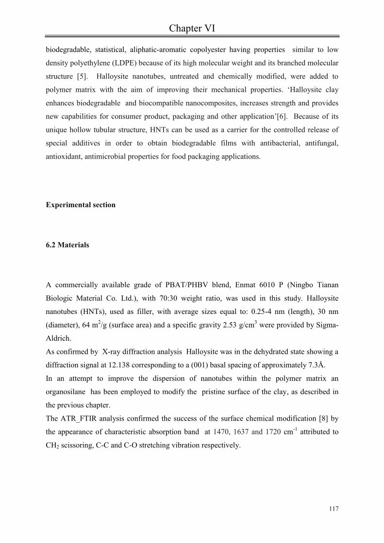
Chapter VI
117
biodegradable, statistical, aliphatic-aromatic copolyester having properties similar to low
density polyethylene (LDPE) because of its high molecular weight and its branched molecular
structure [5]. Halloysite nanotubes, untreated and chemically modified, were added to
polymer matrix with the aim of improving their mechanical properties. ‘Halloysite clay
enhances biodegradable and biocompatible nanocomposites, increases strength and provides
new capabilities for consumer product, packaging and other application’[6]. Because of its
unique hollow tubular structure, HNTs can be used as a carrier for the controlled release of
special additives in order to obtain biodegradable films with antibacterial, antifungal,
antioxidant, antimicrobial properties for food packaging applications.
Experimental section
6.2 Materials
A commercially available grade of PBAT/PHBV blend, Enmat 6010 P (Ningbo Tianan
Biologic Material Co. Ltd.), with 70:30 weight ratio, was used in this study. Halloysite
nanotubes (HNTs), used as filler, with average sizes equal to: 0.25-4 nm (length), 30 nm
(diameter), 64 m2/g (surface area) and a specific gravity 2.53 g/cm
3 were provided by Sigma-
Aldrich.
As confirmed by X-ray diffraction analysis Halloysite was in the dehydrated state showing a
diffraction signal at 12.138 corresponding to a (001) basal spacing of approximately 7.3Å.
In an attempt to improve the dispersion of nanotubes within the polymer matrix an
organosilane has been employed to modify the pristine surface of the clay, as described in
the previous chapter.
The ATR_FTIR analysis confirmed the success of the surface chemical modification [8] by
the appearance of characteristic absorption band at 1470, 1637 and 1720 cm-1
attributed to
CH2 scissoring, C-C and C-O stretching vibration respectively.

Chapter VI
118
6.3 Preparation of bio-nanocomposites
The bio-nanocomposite of Enmat with various organically modified and natural HNTs was
prepared using melt blending technique in a co-rotating twin screw extruder (HAAKE
PolyLab, L/D=40). The matrix was melt mixed with nanoclays at different weight percentage
(3, 5, 10 wt%) at a temperature difference from feed to die zone between 150 °C and 165 °C
and screw speed of 100 rpm. The materials, opportunely pre-dried in a vacuum oven at 70°C
for 12 hr, were pre-mixed by tumbling them in a closed plastic container.
Pure Enmat was also extruded under the same conditions to use as reference material.
Systematic thermogravimetric measurements, shown in chapter IV , confirmed the good
agreement between nominal and actual filler contents.
Table 6.1 summarizes the compositions of composites and the abbreviation used in this
work.
Formulation Abbrevation
PBAT/PHBV
PBAT/PHBV+3% Halloysite
PBAT/PHBV+5%Halloysite
PBAT/PHBV+10%Halloysite
PBAT/PHBV+3% silanized Halloysite
PBAT/PHBV+5% silanized Halloysite
PBAT/PHBV+10%silanized Halloysite
Enmat
3%HNTs
5%HNTs
10%HNTs
3% f-HNTs
5% f-HNTs
10% f-HNTs
TAB. 6.1 Enmat/HNTs nanocomposite systems
6.4 Preparation of blown films
Film blowing of all extruded materials was accomplished using COLLIN single screw
extruder (25:1 L/D) with three individually controlled temperature zones. The extruder was
equipped with a COLLIN TEACH LINE BL50T with a diameter die of 30 mm, and a die-
gap of 0.8 mm was used. The velocity of the take-off rolls and the pressure inside the film
‘‘bubble’’ were adjusted in order to achieve a stable process and to avoid a double-walled

Chapter VI
119
film impossible to separate after passage through the take up roll (blocking). The screw
rotation speed was 27 rpm and the temperature profile equal to 160–175–175–165–160°C
from the hopper to the die. Films having a thickness approximately equal to 35 μm were
manufactured with a blow up ratio (BUR) of 3.3 and maintaining the longitudinal draw ratio
(DR) of 7. The homogeneity of the thickness of the film were quantitatively measured by
cutting a 1m long film for all materials and measuring the thickness on at least five positions
every 20 cm.
Optically the clarity of the films was not compromised by the addition of the fillers both
untreated and modified ones(Fig.6.1).
FIG.6.2 Film samples at different percentages of Halloysites

Chapter VI
120
6.5 Characterization Techniques
6.5.1 Tensile test
Tensile tests were performed at room conditions using a 5 kN load cell on a Thensometer
2020 Alpha Technologies. All measurements were carried out according to the ASTM D882-
02. Tensile specimens, rectangular strips, were cut both in the flow direction of the extruder
(MD) and in the perpendicular direction (TD). The gauge length was set at 50 mm and the
deformation of specimens was set to a double speed, 25 mm/min for the determination of
modulus and then 200 mm/min. At least five samples were tested for each investigated
materials. Results reported in terms of tensile strength, yield stress, elongation at break and
tensile modulus were always averaged on at least five tests.
FIG 6.3 Shape of the tensile test sample.

Chapter VI
121
6.5.2 Dynamic-Mechanical Analysis (DMA)
Dynamic mechanical analysis were assessed using a DMA TRITEC 2000 over the
temperature range from -80°C to 100°C ( heating rate 4°C/min) at an applied frequency of
1 Hz and strain amplitude of 0,01 mm.
A strain amplitude sweep test at 1 Hz frequency was carried out to assure that the tests were
in the linear viscoelasticity region.
The tension mode method was used to measure storage modulus (E’), loss modulus (E’’)
and tan δ parameter of each sample.
The effective specimen size was 5x10x0,035 mm3. A pre-tension of 1 N was applied on the
specimens to avoid its slackening during the vibration.
FIG.6.4 Illustration of a tension mode clamp in DMA
6.6 Morphological analysis
Morphological feautures of films were highlighted by using a Scanning Electron Microscope
(Philiphs XL 20 Series , with an accelerating voltage of 30.0 kV).
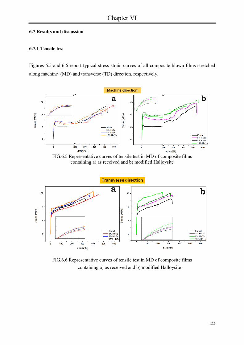
Chapter VI
122
6.7 Results and discussion
6.7.1 Tensile test
Figures 6.5 and 6.6 report typical stress-strain curves of all composite blown films stretched
along machine (MD) and transverse (TD) direction, respectively.
FIG.6.5 Representative curves of tensile test in MD of composite films
containing a) as received and b) modified Halloysite
FIG.6.6 Representative curves of tensile test in MD of composite films
containing a) as received and b) modified Halloysite

Chapter VI
123
MD stress –strain curves showed a necking behavior which gradually propagates until all the
material is cold drown. Finally, the stress increased until failure takes place and a strain
hardening was observed .
About TD tests, instead, the necking disappeared, except in the specimens containing 10%
HNTs and 3% f-HNTs.
It is evident that the inclusion of clay nanotubes induces an increase of the stress at yield,
especially in presence of functionalized fillers. Analogously, an increase of the tensile
strength and negligible effects on the elongation at break are observed for the composite
systems with respect to the neat film . In particular, focusing the attention on samples
containing untreated HNTs, the increase of yield stress verified by the addition of 5 wt% of
nanotubes seems to be not further enhanced by increasing the filler loading (10 wt%). This
behaviour has been attributed to probable agglomerations of nanotubes, reducing the effective
surface area which can undergo filler-matrix interactions.
In terms of stiffness, as clearly highlighted by expanding the low-strain region of the stress-
strain curve, as expected, the inclusion of rigid nanofillers results in an increasing of the
tensile modulus of the composite film samples. This effect is not strictly proportional to the
clay nanotubes content and it essentially occurrs without detrimental effects on the ultimate
mechanical properties. In general, the inclusion of nanotubes up to 10% leads to a stiffness
increase of the film samples, especially in presence of silanized ones. In particular, in MD, at
equal filler content, the Young’s modulus of the composite films with functionalized HNTs
was increased approximately 60% with respect to the neat matrix, while in TD this benefit
was more restrained. At this regard, considering that preliminary calorimetric investigations
(chapter IV) have shown a negligible influence of the clay nanotubes on the hosting matrix
crystallinity, the improvement of the tensile strength and modulus, without a significant loss
in ductility, has been essentially ascribed to a satisfactory adhesion between the clay
nanotubes and the matrix and the occurrence of an adequate distribution of the inorganic
phase. As a consequence, an efficient stress transfer at the matrix-filler interface is obtained.
Mechanical properties are higher in the MD than in the TD. This is attributable to orientation
of the clay in the plane of the film (as confirmed by XRD analysis in the chapter 4).
Figures 6.7 and 6.8 show the evolution of the yield stress and Young’s modulus (determined
from the initial slope of the stress-strain curves) as a function of the halloysite content
comparing systems containing untreated and functionalized nanotubes.

Chapter VI
124
FIG. 6.7 Modulus as function of HNTs loading in machine
(MD) and transverse (TD) direction
FIG. 6.7 Stress at yield as function of HNTs loading in machine
(MD) and transverse (TD) direction

Chapter VI
125
In table 6.2 the tensile parameters of composite films are summarized.
Filler content E (MPa) σY (MPa) σ
b (MPa) ε
b (%) Direction
0 228 (±21) 5,7 (±0,4) 10,3 (±0,5) 313(±65) TD
398 (±42) 6,1 (±0,3) 12,4 (±1,0) 536 (±22) MD
3% HNTs 208 (±19) 6,7 (±0,8) 11,2 (±0,4) 401 (±60) TD
450 (±27) 7,9 (±0,4) 14,3 (±0,6) 565 (±15) MD
5% HNTs 261(±10) 6,2 (±0,3) 10,6 (±0,8) 366 (±15) TD
465 (±36) 7.9 (±0,2) 11,3 (±0,9) 533 (±61) MD
10% HNTs 274 (±18) 6,0 (±0,4) 11,8 (±0,6) 414 (±39) TD
466 (±10) 7,7 (±0,3) 12,6 (±0,4) 540 (±40) MD
3% f-HNTs 244 (±15) 7,2(±0,6) 11,5 (±0,3) 368 (±42) TD
622 (±41) 9,8 (±0,5) 14,1 (±0,6) 569 (±26) MD
5% f-HNTs 262(±15) 7,2 (±0,5) 10,8 (±0,3) 321 (±32) TD
653(±23) 11,2(±0,4) 16,3 (±0,9) 629 (±27) MD
10% f-HNTs 304 (±32) 8,2 (±0,6) 11,0 (±0,9) 265 (±47) TD
590 (±16) 10,5(±0,3) 12,5 (±0, 4) 436 (±66) MD
TAB.6.2 Tensile parameters of Enmat/HNTs composite films
The interfacial interaction between the fillers and matrix is an important factor affecting the
mechanical properties of composites. The behaviour of the tensile yield strength has been
modelled in terms of adhesion. At this regard the Nicolais-Narkis model [9], predicting the
tensile strength of nanocomposites without adhesion between the matrix and the
nanoparticles, has been considered . In this case the interfacial layer would be unable to
transfer stress.
The general expression of the model is the following:
where y,c and y,m are the yield stress values of the composite and of the neat matrix,
respectively; is the volume fraction of the filler while and are constants related to filler-
matrix interaction and geometry of the filler, respectively. In the absence of interfacial
adhesion, the model may be expressed by this simple expression:
1,, mycy

Chapter VI
126
The volume fraction of the filler determined by the following:
where ρm is matrix density(1,25 g/cm3) and ρc is filler one (2,53 g/cm
3).
In table 6.3 are reported the values of volume fractions of halloysite nanoparticles.
TAB. 6.3 Volume fraction of HNTs
The plot of the experimental and theoretical tensile yield stress ratio of the composite and
matrix versus HNTs content is shown (Figure 6.8).
FIG 6.8 Comparison of experimental and theoretical tensile yield stress
ratio of the composites and matrix.
Wf (wt%) (vol%)
3,00 1,50
5,00 2,53
10,00 5,20
32
,
,21.11
my
cy
cfcmfm WW /

Chapter VI
127
Clearly, the experimental values are always higher than the theoretical ones: sign of the
presence of a certain level of interfacial adhesion between the clay nanotubes and the hosting
matrix. This effect is more pronounced in presence of functionalized filler especially in MD.
Consequently, the applied stress can be easily transferred from the polymer matrix to the
halloysite nanoparticles.
On the other hand, to quantify the level of adhesion at the filler-matrix interface, yield
strength values have been also modelled by the Pukanszky model [10,11].
This model assumes that an interphase forms spontaneously in composites and that the yield
stress changes proportionally to its actual value as a function of filler volume fraction
according to following equation:
where σy,c and σy,m are the yield stress of the composite and the matrix, respectively, φ is the
volume fraction of the filler in the composites, and B is a parameter related to the
macroscopic characteristics of the filler-matrix interface and interphase.
t, yi, Af, f are the thickness of the interface, the strength of interaction, the specific surface
area and density of the filler, respectively.
Generally, if the value of “B” is zero, the filler acts as a void, and the value of ‘‘B’’ depends
on the factor influencing the load bearing capacity such as strength and thickness of the
interface.
Otherwise, the higher the ‘‘B’’ value, the stronger are the surface interactions (via thickness
and/or strength). As reported in literature, the ‘‘B’’ value for polymer nanocomposites
ranges between 2 and 15 depending on the interaction level [12].
)exp(5.21
1
,
,
B
my
cy
myiyff tAB ,, /ln1

Chapter VI
128
FIG. 6.9 B parameter for different nanocomposite films evaluated in
machine (MD) and transverse(TD) direction
Comparing the measured tensile yield stress values with those calculated using Pukanszky
model along the transverse (TD) direction, the surface treatment of halloysites leads to the
highest value of the B parameter as a sign of strongest surface interactions. Experimental
values match Pukanszky predictions quite well.
In machine (MD) direction, instead, considering systems with modified HNTs, the calculated
B parameter is 16,2 which indicates a considerable load transfer mechanism. The model fit
leads to lower σy values. However, the mechanical properties of composite materials are
strongly influenced by anisotropy and orientation of the nanofillers and these issues are not
evaluated in the model.
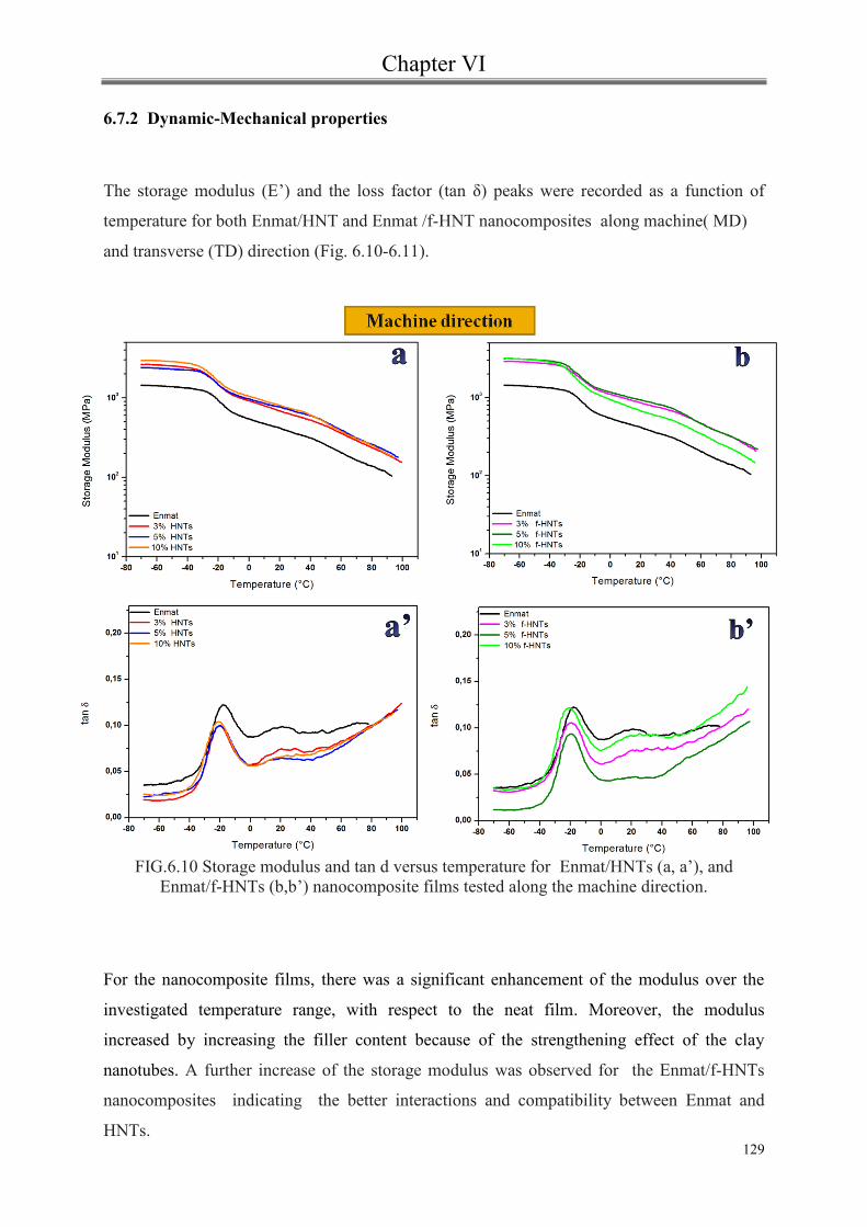
Chapter VI
129
6.7.2 Dynamic-Mechanical properties
The storage modulus (E’) and the loss factor (tan δ) peaks were recorded as a function of
temperature for both Enmat/HNT and Enmat /f-HNT nanocomposites along machine( MD)
and transverse (TD) direction (Fig. 6.10-6.11).
FIG.6.10 Storage modulus and tan d versus temperature for Enmat/HNTs (a, a’), and
Enmat/f-HNTs (b,b’) nanocomposite films tested along the machine direction.
For the nanocomposite films, there was a significant enhancement of the modulus over the
investigated temperature range, with respect to the neat film. Moreover, the modulus
increased by increasing the filler content because of the strengthening effect of the clay
nanotubes. A further increase of the storage modulus was observed for the Enmat/f-HNTs
nanocomposites indicating the better interactions and compatibility between Enmat and
HNTs.

Chapter VI
130
When the modified clay content is 10% wt, the agglomeration of HNTs weakens the
interaction between the matrix and the nanoparticles so the storage modulus increases but to
a lesser extent .
Noticeable difference was not seen between the properties in the machine direction and the
transverse direction for the blown films. In the cross direction the filler effects on the storage
modulus are less pronounced than those shown before. This could be a further validation of
the orientation of clay nanotubes along the machine direction.
Nevertheless, the decrease of the storage modulus with increasing temperature is less
pronounced in all the examined nanocomposite films .
FIG.6.10 Storage modulus and tan d versus temperature for Enmat/HNTs (a, a’), and
Enmat/f-HNTs (b,b’) nanocomposite films tested along the transverse direction.
The elasticity of a material is measured by tan δ, which is the ratio of energy dissipated to

Chapter VI
131
energy stored per cycle. Thus, elasticity is inversely proportionate to tan δ [13].
In the machine direction nanocomposite films were more elastic than neat Enmat as shown by
lower tan δ (fig.6.9 a’,b’). The height of the damping peaks of nanocomposite films , in fact,
was lower than those of PHBV/PBAT matrix. This is a consequence of the reduced matrix
molecular mobility caused by the nanotubes which affect the polymer chain relaxation. The
values of glass transition temperature (Tg) were obtained from the temperature corresponding
to tanδ peak. As it can be seen from the fig. 6.9 (b,b’), the pure Enmat showed two distinct
transitions: one at -20°C, which corresponds to the glass-rubber transition of PBAT and the
other at 20 °C, related to the transition of the hard rigid PHBV phase.
The presence of HNTs significantly reduced the height of the peak related to the transition of
PHBV.
To summarize, in the table 6.4 the glassy and rubbery storage modulus values for all
investigated film samples are reported.
The data confirm the increase of the storage modulus by addition of halloysites especially for
samples tested along the longitudinal direction. This effect, not proportional to the filler
loading, appears to be more pronounced in presence of modified halloysites.
TAB. 6.4 Comparative DMA data of Enmat nanocomposites containing
HNTs and f- HNTs
About the glass transition temperature, no significant variation can be observed.

Chapter VI
132
6.8 Morphological analysis
A homogeneous dispersion of halloysites and strong interfacial interactions between polymer
matrix and nanotubes can effectively improve the mechanical properties of polymer
nanocomposites [16,17,18].
FIG.6.11 Comparison of SEM images of nanocomposite films containing 3 wt % of
unmodified and functionalized halloysites

Chapter VI
133
FIG.6.12 FIG.6.11 Comparison of SEM images of nanocomposite films containing 5 wt % of
unmodified and functionalized halloysites
The SEM images of Enmat /HNTs and Enmat /f-HNTs nanocomposite films are shown in
Figure 6.11-6.12. The dispersion of unmodified halloysites (HNTs) is not very good and
whereas some aggregates are visible (marked as A). In case of nanocomposites with
functionalized halloysites, the nanotubes are uniformly dispersed and distributed in the
matrix even at high HNTs loading.
Moreover a good interface is observed between HNTs and Enmat matrix. Halloysite
nanotubes (marked as B) appear to be not extensively debonded as well as visibly embedded
in the Enmat matrix. Most HNTs are broken rather than pulled out from the polymer matrix .

Chapter VI
134
6.9 Conclusion
Blown films of neat PHBV/PBAT 30/70 w/w blend and its composites containing up to 10
wt% of clay nanotubes have been characterized in terms of mechanical and dynamic
mechanical properties. The influence of both unmodified (HNTs) and silanized halloysiste
nanotubes (f-HNTs) has been analyzed by tests performed in machine and transverse
directions.
Mechanical tests have demonstrated that strength and modulus of nanocomposite systems
significantly increase with addition of halloysites without significant loss of ductility.
Dynamic-mechanical analysis have evidenced a slight decrease in glass transition temperature
as well as an improvement in storage modulus with the incorporation of halloysites especially
in case of surface modified ones. A homogeneous dispersion of the modified nanotubes was
obtained in the Enmat matrix.
Bibliography
135
[1] Understanding plastic film: Its Uses, Benefits and Waste Management Options
Prepared for the American Plastics Council by Headley Pratt Consulting (1996) available
at http://plastics.americanchemistry.com/Understanding-Plastic-Film
[2] Nanda, M. R., Misra, M. and Mohanty, A. K., Macromol. Mater. Eng., 296: 719
(2011)
[3] J. Tao, C.Song, Mingfeng Cao, D. Hu, Li Liu, Na Liu, S. Wang, Polymer
Degradation and Stability, 94, 4,575 (2009)
[4] G. X. Chen, G. J. Hao, T. Y. Guo, M. D. Song, B. H. Zhang Journal of
Materials Science Letters , 21, 20, 1587 (2002)
[5] Smita Mohanty & Sanjay Kumar Nayak Int J Plast Technol 14, 2, 192 (2010)
[6] Aaron L. Wagner, Sarah Cooper, and Michael Riedlinger. Industrial
Biotechnology. Fall, 1,3 190 (2005).
[7] M. Du, B. Guo, and D. Jia, Eur. Polym. J. 42, 1362 (2006).
[8] N.N. Herrera, J.-M. Letoffe, J.-P. Reymond, and E. Bourgeat-Lami, J. Mater.
Chem. 15, 863 (2005).
[9] Nicolais L., Narkis M. Polym. Eng. Sci. 11, 194 (1971)
[10] Pukanszky B. New Polymeric Mater. 3, 205 (1992)
[11] Szazdi, L.; Pukanszky, Jr.; B.; Vancso, G. J. Polymer, 47, 4638 (2003).
[12] Dayma, N.; Satapathy, B. K. Mater. Des. 31, 4693 (2010).
[13] P. Pasbakhsh, H. Ismail, M.N Ahmad Fauzi, A. Abu Bakar. Applied Clay Science,
48, 3, 405 (2010).
[14] Liu, X., Wu, Q.,. Polymer 42, 10013 (2001).
[15] J.S. Shelley, P.T. Mather, K.L. DeVries , Polymer 42, 5849 (2001) .
[16] Prashantha, K.; Soulestin, J.; Lacrampe, M. F.; Krawczak, P.; Dupin, G.; Claes,
M. Compos. Sci. Technol., 69, 1756 (2009).
[17] Gupta B.; Lacrampe, M. F.; Krawczak, P. Polym. Polym. Comp. 14, 13, (2006).
[18] Prashantha, K.; Soulestin, J.; Lacrampe, M. F.; Claes, M.; Dupin, G.; Krawczak,
P. Express Polym. Lett. 2, 735,(2008).

Chapter VII
136
Conclusions

Chapter VII
137
Conclusions
The aim of this study was to develop biodegradable and compostable material with good
performances that can be used in food packaging applications.
Nanocomposites, based on PBAT/PHBV blend and various concentrations of neat or
silanized Halloysite nanotubes, were obtained using melt compounding tecnique and
subsequently blown films were prepared.
The conclusions that could be drawn from this work are the following:
From thermal analysis the simultaneous occurrence for the PHBV phase of both
homogeneous crystallization and heterogeneous nucleation promoted by the
included fillers was observed. These phenomena show effects of mutual entities
depending on the quality of the filler–matrix interface and the applied cooling
rate. On the contrary, for the PBAT phase, although the filler may alter kinetics
and mechanisms of crystallizations, no effect is reported in terms of its degree of
crystallinity. All these evidences have been supported by structural investigations.
Moreover, X-ray diffraction analysis indicated that the process of film blowing
enables the formation of more perfect crystals and, as expected, favors the
orientation of the included nanotubes of clay.
An increase in thermal stability was observed after addition of both untreated and
functionalized halloysites.
From rheological measurements, increase in the complex viscosity and in the
storage moduli of nanocomposites was shown. The effects of filler on viscoelastic
behavior of composite systems are emphasized by improving the filler-matrix
interface. In particular, in presence of the highest loading of silanized halloysite
incipient flocculation phenomena seems to occur. The nanocomposites with the
increasing Halloysites content exhibited higher zero shear viscosities and more
rapid shear thinning behavior than pure matrix, which results from the
reorientation of dispersed clay particles. Shear viscosities were well represented
by the Carreau model.
Chapter VII
138
The filler does not appear to alter the extrudability of the hosting matrix,
remaining the measured viscosity in the same order of magnitude of pure blend.
The choice of processing temperature may be exclusively related to the level of
filler distribution able to ensure optimal viscoelastic behavior of the melts.
Mechanical tests have demonstrated that strength and modulus of nanocomposite
systems significantly increase with addition of halloysites without significant loss
of ductility. Good interfacial adhesion is required for the effective stress transfer
between components in the multi-phase polymer blends. At this regard, in order to
evaluate the interaction level between the filler and the matrix, two model were
considered: the Nicolais-Narkis model and the Pukanszky model.
Dynamic-mechanical analysis have evidenced a slight decrease in glass transition
temperature as well as an improvement in storage modulus with the incorporation
of halloysites especially in case of surface modified ones.
The obtained results showed that these composites films were promising materials for
replacing non degradable materials in specific applications.
The nanocomposites investigated showed improved mechanical properties over that of the
neat polymer. with no reduction in optical transparency. In addition, because of its unique
hollow tubular structure, HNTs can be used as a carrier for the controlled release of
special additives in order to obtain biodegradable films with antibacterial, antifungal,
antioxidant, antimicrobial properties for food packaging applications.


![Halloysite - Texas Rho Chapter of Pi Mu Epsilonpmetxstate.weebly.com/.../slidesreyes110912.pdf · Halloysite Introduction Halloysite [Al 2 (OH) 4 Si 2 O 5 •2H 2 O] is an inorganic](https://static.fdocuments.net/doc/165x107/60a0dac439717f0b810b4694/halloysite-texas-rho-chapter-of-pi-mu-halloysite-introduction-halloysite-al-2.jpg)